EP1592011A2 - Modulator, modulation method, and method of manufacturing an optical recordable medium with enhanced security for confidential information - Google Patents
Modulator, modulation method, and method of manufacturing an optical recordable medium with enhanced security for confidential information Download PDFInfo
- Publication number
- EP1592011A2 EP1592011A2 EP05101451A EP05101451A EP1592011A2 EP 1592011 A2 EP1592011 A2 EP 1592011A2 EP 05101451 A EP05101451 A EP 05101451A EP 05101451 A EP05101451 A EP 05101451A EP 1592011 A2 EP1592011 A2 EP 1592011A2
- Authority
- EP
- European Patent Office
- Prior art keywords
- code
- main information
- information
- data
- converted
- Prior art date
- Legal status (The legal status is an assumption and is not a legal conclusion. Google has not performed a legal analysis and makes no representation as to the accuracy of the status listed.)
- Withdrawn
Links
Images


Classifications
-
- A—HUMAN NECESSITIES
- A45—HAND OR TRAVELLING ARTICLES
- A45B—WALKING STICKS; UMBRELLAS; LADIES' OR LIKE FANS
- A45B9/00—Details
- A45B9/06—Sticks with name-plates or the like
-
- G—PHYSICS
- G11—INFORMATION STORAGE
- G11B—INFORMATION STORAGE BASED ON RELATIVE MOVEMENT BETWEEN RECORD CARRIER AND TRANSDUCER
- G11B20/00—Signal processing not specific to the method of recording or reproducing; Circuits therefor
- G11B20/00086—Circuits for prevention of unauthorised reproduction or copying, e.g. piracy
- G11B20/0021—Circuits for prevention of unauthorised reproduction or copying, e.g. piracy involving encryption or decryption of contents recorded on or reproduced from a record carrier
- G11B20/00217—Circuits for prevention of unauthorised reproduction or copying, e.g. piracy involving encryption or decryption of contents recorded on or reproduced from a record carrier the cryptographic key used for encryption and/or decryption of contents recorded on or reproduced from the record carrier being read from a specific source
- G11B20/00253—Circuits for prevention of unauthorised reproduction or copying, e.g. piracy involving encryption or decryption of contents recorded on or reproduced from a record carrier the cryptographic key used for encryption and/or decryption of contents recorded on or reproduced from the record carrier being read from a specific source wherein the key is stored on the record carrier
- G11B20/00362—Circuits for prevention of unauthorised reproduction or copying, e.g. piracy involving encryption or decryption of contents recorded on or reproduced from a record carrier the cryptographic key used for encryption and/or decryption of contents recorded on or reproduced from the record carrier being read from a specific source wherein the key is stored on the record carrier the key being obtained from a media key block [MKB]
-
- G—PHYSICS
- G11—INFORMATION STORAGE
- G11B—INFORMATION STORAGE BASED ON RELATIVE MOVEMENT BETWEEN RECORD CARRIER AND TRANSDUCER
- G11B20/00—Signal processing not specific to the method of recording or reproducing; Circuits therefor
- G11B20/00086—Circuits for prevention of unauthorised reproduction or copying, e.g. piracy
- G11B20/0021—Circuits for prevention of unauthorised reproduction or copying, e.g. piracy involving encryption or decryption of contents recorded on or reproduced from a record carrier
- G11B20/00485—Circuits for prevention of unauthorised reproduction or copying, e.g. piracy involving encryption or decryption of contents recorded on or reproduced from a record carrier characterised by a specific kind of data which is encrypted and recorded on and/or reproduced from the record carrier
- G11B20/00492—Circuits for prevention of unauthorised reproduction or copying, e.g. piracy involving encryption or decryption of contents recorded on or reproduced from a record carrier characterised by a specific kind of data which is encrypted and recorded on and/or reproduced from the record carrier wherein content or user data is encrypted
-
- G—PHYSICS
- G11—INFORMATION STORAGE
- G11B—INFORMATION STORAGE BASED ON RELATIVE MOVEMENT BETWEEN RECORD CARRIER AND TRANSDUCER
- G11B20/00—Signal processing not specific to the method of recording or reproducing; Circuits therefor
- G11B20/00086—Circuits for prevention of unauthorised reproduction or copying, e.g. piracy
- G11B20/00572—Circuits for prevention of unauthorised reproduction or copying, e.g. piracy involving measures which change the format of the recording medium
- G11B20/00579—Circuits for prevention of unauthorised reproduction or copying, e.g. piracy involving measures which change the format of the recording medium said format change concerning the data encoding, e.g., modulation schemes violating run-length constraints, causing excessive DC content, or involving uncommon codewords or sync patterns
-
- G—PHYSICS
- G11—INFORMATION STORAGE
- G11B—INFORMATION STORAGE BASED ON RELATIVE MOVEMENT BETWEEN RECORD CARRIER AND TRANSDUCER
- G11B20/00—Signal processing not specific to the method of recording or reproducing; Circuits therefor
- G11B20/00086—Circuits for prevention of unauthorised reproduction or copying, e.g. piracy
- G11B20/0092—Circuits for prevention of unauthorised reproduction or copying, e.g. piracy involving measures which are linked to media defects or read/write errors
- G11B20/00927—Circuits for prevention of unauthorised reproduction or copying, e.g. piracy involving measures which are linked to media defects or read/write errors wherein said defects or errors are generated on purpose, e.g. intended scratches
-
- A—HUMAN NECESSITIES
- A45—HAND OR TRAVELLING ARTICLES
- A45B—WALKING STICKS; UMBRELLAS; LADIES' OR LIKE FANS
- A45B2200/00—Details not otherwise provided for in A45B
- A45B2200/10—Umbrellas; Sunshades
- A45B2200/1081—Umbrella handles
-
- G—PHYSICS
- G11—INFORMATION STORAGE
- G11B—INFORMATION STORAGE BASED ON RELATIVE MOVEMENT BETWEEN RECORD CARRIER AND TRANSDUCER
- G11B20/00—Signal processing not specific to the method of recording or reproducing; Circuits therefor
- G11B20/10—Digital recording or reproducing
- G11B20/14—Digital recording or reproducing using self-clocking codes
- G11B20/1403—Digital recording or reproducing using self-clocking codes characterised by the use of two levels
- G11B20/1423—Code representation depending on subsequent bits, e.g. delay modulation, double density code, Miller code
- G11B20/1426—Code representation depending on subsequent bits, e.g. delay modulation, double density code, Miller code conversion to or from block codes or representations thereof
- G11B2020/1457—Code representation depending on subsequent bits, e.g. delay modulation, double density code, Miller code conversion to or from block codes or representations thereof wherein DC control is performed by calculating a digital sum value [DSV]
Definitions
- the present invention relates to a modulator which replaces a part of main information with specific information.
- confidential information that is not intended for disclosure to users is recorded on a recording medium such as a CD (Compact Disk), a DVD (Digital Versatile Disk), and the like.
- a recording medium such as a CD (Compact Disk), a DVD (Digital Versatile Disk), and the like.
- contents such as images, sounds, texts, and the like are encoded and recorded onto the recording medium
- an encryption key for decoding the contents as confidential information are recorded. This enables both reproduction of the contents and prevention of illegal copy thereof to thereby protect a copyrighted work contained in the contents.
- main information and confidential information are modulated by a first and a second modulation method respectively to generate main information modulation signal and confidential information modulation signal, a part of the main information modulation signal is replaced with the confidential information modulation signal, and a resultant signal is recorded onto a recording medium.
- an embedded signal in which the confidential information modulation signal is embedded in the main information modulation signal is recorded onto the recording medium.
- the main information can be reproduced.
- error correction processing is performed for the embedded signal, whereby the main information before replacement with the confidential information can be reproduced. It is difficult to reproduce the confidential information unless the second modulation method is used, so that the secret state of the confidential information can be maintained.
- error propagation may occur in the main information.
- the portion in the main information replaced with the confidential information becomes an error in the main information, and an error may occur in the main information at portions other than this.
- This error propagation can be caused by modulation processing at a connection boundary between the main information and the confidential information.
- the embedding of the confidential information into the main information causes disturbance in direct-current component suppress processing performed for the main information, which may cause deterioration in direct-current component suppress characteristics.
- the signal characteristics of the main information may deteriorate due to the embedding of the specific information such as confidential information and the like into the main information.
- embodiments of the invention provide a modulator which reduces the deterioration in signal characteristics of the main information when embedding specific information such as confidential information and the like into the main information.
- a modulator which includes: a main information converter configured to code-convert main information by a first modulation method; a specific information converter configured to code-convert specific information by a second modulation method different from the first modulation method; a replacement unit configured to replace a part of the code-converted main information with the code-converted specific information; and a direct-current component suppressing unit configured to suppress direct-current components of the replaced main information.
- a modulator which includes: a main information converter configured to code-convert main information by a first modulation method based on state information; a specific information converter configured to code-convert specific information by a second modulation method different from the first modulation method; a replacement processing unit configured to replace a part of the code-converted main information with the code-converted specific information and output the resultant information as a channel bit stream; a DSV controller configured to calculate a digital sum value of the channel bit stream; and a state register configured to output the state information in accordance with the replacement result and the calculated digital sum value.
- a modulator which includes: a main information converter configured to code-convert main information by a first modulation method; a specific information converter configured to code-convert specific information by a second modulation method different from the first modulation method; a replacement processing unit configured to replace a part of the code-converted main information with the code-converted specific information and output the resultant information as a channel bit stream; a DSV controller configured to calculate a digital sum value of the channel bit stream and to suppress direct-current components of the replaced main information.
- a modulator which includes: a main information converter configured to code-convert main information by a first modulation method based on state information; a specific information converter configured to code-convert specific information by a second modulation method different from the first modulation method based on state information; a replacement processing unit configured to replace a part of the code-converted main information with the code-converted specific information and output the resultant information as a channel bit stream; a converted information outputting unit configured to output at least one of the converted information selected from the code-converted main information the code-converted specific information in accordance with the replacement result of the replacement processing unit; a DSV controller configured to calculate a digital sum value of the channel bit stream; and a state register configured to output the state information in accordance with the output from the converted information outputting unit and the output from the DSV controller.
- a modulator which includes: a main information storing device storing a first main information conversion table showing main information data before code-conversion, next state information, and a first code after code-conversion based on state information and a second main information conversion table showing main information data before code-conversion, next state information, and a second code after code-conversion based on state information; a main information converter configured to code-convert main information based on said first and second main information conversion tables and output the code-converted main information by channel bits of predetermined length to first and second terminals respectively; a first DSV calculator configured to calculate first digital sum values of the code-converted main information outputted from the first terminals; a second DSV calculator configured to calculate second digital sum values of the code-converted main information outputted from the second terminals; a state information decision unit configured to decide state information to be used in said main information conversion table based on the first and second calculated digital sum values; an even/odd judging unit configured to judge
- a modulator which includes: a main information converter configured to code-convert main information by a first modulation method; a connection rule processing unit configured to generate a main information modulation signal from the code-converted main information based on a connection rule table showing combinations of adjacent channel bits before and after processing; a specific information converter configured to code-convert specific information by a second modulation method, different from the first modulation method, to generate a specific information modulation signal including a pattern that is not used in the first modulation method; and a replacement unit configured to replace a part of the generated main information modulation signal with the generated specific information modulation signal.
- the generated specific information modulation signal may be divided into a plurality of parts (for example, a header part and an end part, or three or more parts), and one or more of the parts includes a pattern which is not used in the first modulation method.
- the generated specific information modulation signal may be divided into a plurality of parts (for example, a header part and an end part, or three or more parts), and a combination of two or more of the parts includes a combination being not used by the connection rule processing unit.
- the connection rule processing unit may generate a main information modulation signal with a run length limited to a predetermined range, and the pattern is a pattern having a run length exceeding the predetermined range.
- a modulation method which includes: storing a first main information conversion table storing main information data before code-conversion, next state information, and a first code after code-conversion based on state information and a second main information conversion table showing main information data before code-conversion, next state information, and a second code after code-conversion based on state information; code-converting main information based on said first andsecondmain information conversion tables and outputting the code-converted main information by channel bits of predetermined length to first and second terminals respectively; calculating a first digital sum values of the code-converted main information outputted from the first terminal; calculating a second digital sum values of the code-converted main information outputted from the second terminal; determining state information to be used in said main information conversion table based on the first and second calculated digital sum values; judging whether the number of 1s in an area of the code-converted main information into which specific information is embedded is even or odd; code-converting specific information by a second modulation method different from
- a modulation method which includes: code-converting a main information by a first modulation method, said main information being constituted of channel bits of a predetermined length; generating a main information modulation signal from the code-converted main information based on a connection rule table showing combinations of adjacent channel bits before and after processing; code-converting specific information by a second modulation method, different from the first modulation method, to generate a specific information modulation signal including a pattern that is not used in the first modulation method; and replacing a part of the generated main information modulation signal with the generated specific information modulation signal.
- a method of manufacturing a master disk which includes: generating encoded contents data; generating encoded master key data used for decoding said encoded contents; generating main information including proprietary data; generating confidential information different from said proprietary data; code-converting said main information by a first modulation method; code-converting said specific information by a second modulation method different from the first modulation method; replacing a part of the code-converted main information with the code-converted specific information to output a channel bit stream; suppress direct-current components of the replaced main information; and embedding said encoded content, said encoded master key data, and said suppressed channel bit stream on a master recordable medium.
- a method of manufacturing a master disk which includes: generating encoded contents data; generating encoded master key data used for decoding said encoded contents; generating main information including proprietary data; generating confidential information different from said proprietary data; code-converting said main information by a first modulation method, said main information being constituted of channel bits; generatingamain information modulation signal from the code-converted main information based on a connection rule table showing combinations of adjacent channel bits before and after processing; code-converting said specific information by a second modulation method, different from the first modulationmethod, to generate a specific information modulation signal including a pattern that is not used in the first modulation method; replacing a part of the generated main information modulation signal with the generated specific information modulation signal to generated encoded output data; and embedding said encoded content, said encoded master key data, and said encoded output data on a master recordable medium.
- a method of manufacturing an optical recordable medium which includes: generating encoded master key data; generating main information including proprietary data; generating confidential information different from said proprietary data; code-converting said main information by a first modulation method, said main information being constituted of channel bits; generating a main information modulation signal from the code-converted main information based on a connection rule table showing combinations of adjacent channel bits before and after processing; code-converting said specific information by a second modulation method, different from the first modulation method, to generate a specific information modulation signal including a pattern that is not used in the first modulation method; replacing a part of the generated main information modulation signal with the generated specific information modulation signal to generated encoded output data; and embedding said encoded master key data, and said encoded output data on said recordable medium.
- a modulator which includes: a main information converter configured to code-convert main information by a first modulation method; a specific information converter configured to code-convert specific information by a second modulation method different from the first modulation method; a direct-current component suppressing unit configured to suppress direct-current components of the code-converted main information; a replacement unit configured to replace a part of the suppressed code-converted main information with the code-converted specific information.
- a modulator which includes: a main information converter configured to code-convert main information by a first modulation method; a connection rule processing unit configured to generate a main information modulation signal from the code-converted main information based on a connection rule table showing combinations of adjacent channel bits before and after processing; a specific information converter configured to code-convert specific information by a second modulation method, different from the first modulation method, to generate a specific information modulation signal including a pattern that is not used in the first modulation method; a direct-current component suppressing unit configured to suppress direct-current components of the code-converted main information; a replacement unit configured to replace a part of the suppressed code-converted generated main information modulation signal with the generated specific information modulation signal.
- FIG. 1 is a diagram representing a disk recording device according to a first embodiment of the present invention.
- MM media mark
- MKB media key block
- RP-Data proprietary data
- the contents data is data representing images, sounds and so on. Since this contents data is encoded and then written to the recording medium D, the data is typically in the form of encoded contents (Enc-contents) which have been encoded before inputted into the device shown in FIG. 1. In this drawing, it is not necessary to distinguish contents before encoding (plain text) from the encoded contents, and the encoded contents are therefore referred to simply as contents data.
- MKB media key block
- RP-Data proprietary data
- MM media mark
- the media key block (MKB) and the media mark (MM) are elements of an encryption key for decoding the encoded contents.
- This proprietary data is data to be a subject of ownership of a copyright, a trademark, a well-known name, or the like.
- the proprietary data (RP-Data) is data having a characteristic of copyrighted work, such as data or the like of images and sounds, it becomes a subject of copyright.
- the proprietary data (RP-Data) exhibits a function of trademark, it can be a subject of trademark.
- One case of exhibiting the function of trademark is that a design of the trademark is reproduced when an optical disk 10 is set in a disk drive (reproducing device). This is because the proprietary data will be recognized as a trademark by a customer as a result of performing demonstration in a sales shop for example.
- the media key block (MKB) and the proprietary data (RP-Data) are regarded as the main information and the media mark (MM) is regarded as the confidential information, but this division is not absolute in a sense and a division different therefrom is also possible.
- What is processed with the contents data is regarded as the main information, and information to be embedded in the main information is regarded as the confidential information (a kind of specific information).
- the main information (MKB, Contents Data, RP-Date) is inputted into a data frame generator R01 and arranged in a data frame structure constituted of a 2K-byte data packet.
- IED ID error detection code
- ID: Sector-ID sector identifier
- the data frame generated in the data frame generator R01 is inputted into an EDC generator R02 where the sector identifier (ID) and auxiliary data (RSB) are added to the data frame and an error detection code (EDC) is generated and added to the data frame (see FIG. 12 described later) .
- the data frame outputted from the EDC generator R02 is inputted into a scramble unit R03 where a scramble signal is superimposed on the main information in the data frame.
- This scramble signal is typically decided based on a part of data of the sector identifier (ID).
- ID sector identifier
- the data frame after undergoing the scramble processing is inputted into an ECC block generator R031 where 15 sets of the data frames create an ECC block.
- the ECC block is inputted into a PO/PI generator R051 where an error correcting outer parity PO and inner parity PI are generated and added to the ECC block (see FIG. 13 described later).
- the ECC block outputted from the PO/PI generator R051 is inputted into a PO interleave unit R06 where the error correcting outer parity PO in the ECC block is dispersed (see FIG. 14 described later).
- the ECC block includes recording sectors to which the error correcting outer parity PO row are dispersed and the error correcting inner parity PI are added. These recording sectors are modulated and have synchronization signals added thereto in a synchronization signal addition & first modulator R07.
- the media mark (MM) is given a media mark parity (MM-Pa) to become a correcting code added media mark (MM+MM-Pa) in a media mark parity generator R11 and modulated in a second modulator R13.
- MM-Pa media mark parity
- MM+MM-Pa correcting code added media mark
- the modulated recording sector and modulated media mark are inputted into a media mark (MM) replacing unit R14 where a part of a main information modulation signal in the recording sector is replaced with a media mark modulation signal to generate a recording signal (see FIG. 15 described later).
- This recording signal is written to the recording medium D by a recording medium writing unit R08.
- synchronization signal (Sync) addition & first modulator R07, second modulator R13, and media mark (MM) replacing unit R14 modulate the main information and embed the confidential information, and therefore all of these are regarded as a modulator R071.
- FIG. 2 is a block diagram representing details of an internal configuration of the modulator R071 shown in FIG. 1. However, a part on the synchronization signal addition is omitted.
- the code table unit 11, a state register 12, and a code connector 13 in this drawing correspond to the first modulator R07 in FIG. 1
- a media mark modulator 14 in this drawing corresponds to the second modulator R13
- a switch S and a DSV controller 15 in this drawing correspond tothemediamark(MM) replacing unit R14, respectively.
- the switch S may be considered as corresponding to he replacing unit R14 with the DSV controller 15 as an added component of modulator R071.
- the code table unit 11 and code connector 13 may be considered as constituting the first modulator R07 with the state register 12 as an added component of the modulator.
- the main information is inputted into the code table unit 11 as a data word B(t) and code-converted into a conversion code (code word) X(t).
- the code table unit 11 is stored in a memory or storage device which is accessed for code conversion.
- the code table 11, in which a plurality of states are prepared for one data word, is used to perform code-conversion based on a state selected by a selection signal from the state register. In this drawing, the code table unit 11 selects a state S(t) corresponding to the data word B (t) and outputs instruction data for a next state S(t+1) .
- the instruction signal for the next state S(t+1) is stored in the state register 12 and used for selection for a state of a next conversion code (Data word) B(t+1).
- the conversion code X(t) outputted from the code table unit 11 is sent to the code connector 13 and subjected to processing under a conversion symbol connection rule so as to be converted into connected code words.
- the code connector 13 converts the conversion code into another pattern.
- conversion codes of data words symbols
- the media mark modulator 14 being the confidential information modulator code-converts the media mark (MM) to generate a media mark word (MM Code Word) . This conversion is based on a conversion rule different from that for the main information.
- the switch S switches between the connected code words (main information) and the media mark conversion code (confidential information) as the signal to be inputted into the DSV controller 15 to thereby replace a part of the main information with the confidential information.
- the confidential information is embedded in the main information.
- the DSV controller 15 inverts a part of bit information of the signal inputted thereinto to control such that the direct-current component in the NRZI signal being a recording signal alternates near "0". Since the direct-current component of the signal is represented by a digital sum value (DSV), the DSV controller 15 inverts a part of bits of the connected code words such that the digital sum value (DSV) in a predetermined time becomes close to 0 to thereby perform DC component suppress control (DCC).
- DCC DC component suppress control
- the DC component suppress control is therefore performed on a signal with a media mark signal (MM) incorporated therein (a signal with confidential information embedded therein).
- MM media mark signal
- a control signal is sent from the media mark modulator 14 to the code connector 13 to stop the connection rule processing within an area into which the media mark signal (MM) is to be incorporated.
- MM media mark signal
- FIG. 3A is a view showing an example of a code conversion table used in conversion in the code table unit 11. This drawing shows a part of the code conversion table for code-converting the data word (symbol data) of 8 bits each into a code word of 12 channel bits. Each data word is converted into three kinds of code words in accordance with states 0 to 2. A next-state is determined in correspondence with the data word to be converted.
- RLL Random Length Limited Code
- the RLL code is a modulation code of which maximum value and minimum value of continuing 0s are limited, such that, for example, (2,7)RLL means that 0 is permitted to continue from a minimum of 2 times to a maximum of 7 times.
- FIG. 3B is a view showing an example of a connection conversion table used in processing by the code connector 13.
- connection rule processing when two consecutive code words (Previous Code Word and Current Code Word) are the designated pattern, they are converted into a concatenated code word.
- "?” means that the values are kept as they are before and after the connection rule processing.
- FIG. 4A and FIG. 4B are views showing another example of the code conversion table used in conversion by the code table unit 11 and the connection conversion table used in processing by the code connector 13, respectively.
- a case shown here is that the code word after conversion is basically decided in accordance with the data word and therefore the conversion code is state-independent. After the modulation with a (1,7) RLL code in the code table unit 11, the connection rule processing in the code connector 13 is performed.
- FIG. 4A shows a part of the code conversion table for code-converting the data word (symbol data) of 2 bits each into a code word of 12 channel bits .
- the 2-bit data word (Source data) is converted into a 3-bit code word.
- a 4-bit data word constituted by adding next two bits to the data word is converted into a 6-channel code word.
- "X" in this drawing means an inversion signal of a bit subsequent thereto. In other words, "X" becomes “1” if the next bit is "0", or becomes “0” if the next bit is "1".
- FIG. 4B is a view showing another example of the connection conversion table used in processing in the code connector 13.
- the bit stream "100110” is code-converted according to the code conversion table shown in FIG. 4A to result in "010 101 010" in which "01" is repeated.
- This signal is a minimum run length in the (1,7)RLL and becomes difficult to read if this is written to a recording medium as it is. Therefore, the connection rule processing is performed using the connection conversion table shown in FIG. 4B to prevent the repetition of "01" to facilitate reading of this signal from the recording medium on which it is recorded.
- FIG. 5 is a schematic view for explaining a configuration example of the media mark modulation (MM Modulation) signal.
- the channel bit length of the media mark signal can be made longer than the channel bit length of the main information to thereby easily differ the modulation pattern for the media mark signal from the modulation pattern for the main information. More specifically, by increasing the channel bit length of the media mark signal, it becomes possible to incorporate a pattern not in use for the main information channel bit pattern into a part of the channel bits and give a code converting function to the other part. For example, the channel bit length of the media mark signal is made twice the channel bit length of the main information, and a code conversion table for the media mark signal is created.
- the media mark modulation signal is divided into channel bits [A], [B], and [C].
- the channel bit [A] constitutes a header part of the media mark modulation signal, and the channel bits [B] and [C] constitute an end part of the media mark modulation signal.
- a bit pattern not in use in the modulation channel bit pattern for the main information is incorporated.
- a bit pattern obtained by converting the media mark signal is incorporated. This arrangement makes it possible to prevent the original media mark signal from being reproduced even if the media mark modulation signal is inversely converted by the conversion method for the main information, so that the confidentiality of the media mark modulation signal can be maintained. It is possible to use, for the bit pattern for the end part in this event, the media mark signal converted by the conversion rule similar to that for the main information.
- the channel bits [B] and [C] may constitute a middle part and an end part of the media mark modulation signal, respectively.
- a bit pattern that is not in use in the conversion channel bit pattern for the main information can be constituted by combination of the header part and the end part, and the bit pattern obtained by converting the media mark signal can be incorporated into the middle part.
- FIG. 6 is a flowchart illustrating a procedure of embedding a media mark modulation signal into a main information modulation signal.
- connection rule processing for the main information modulation signal adjacent to the embedding position of the media mark modulation signal in the main information modulation signal is limited (Step S11).
- this limitation is implemented by inputting the control information from the media mark modulator 14 to the code connector 13 in FIG. 2.
- the code connection processing which has been once performed may be inversely converted into the original state in place of the limitation on this code connection processing. Not that an example of performing such inverse conversion will be described later.
- the media mark modulation signal is divided into the header part and the end part (Step S12).
- the header part and the end part of the media mark modulation signal are modulated (Steps S13, S14).
- the media mark modulation signal is embedded (Step S15). A part of the main information modulation signal is replaced with the header part and the end part of the media mark modulation signal by switching the switch S at a timing of the header part of the media mark modulation signal, and the resultant signal is inputted into the DSV controller 15. Thereafter, the switch S is returned to the main information modulation signal side, whereby the main information modulation signal is inputted into the DSV controller 15.
- the main information modulation signal with the media mark modulation signal embedded therein is inputted into the DSV controller 15, whereby the DC component is suppressed (Step S16).
- the modulation of the media mark signal can be performed in the following manner.
- the bit pattern of the header part of the media mark modulation signal is decided by the media mark signal A before modulation and the main information modulation signal immediately before this header part.
- the bit pattern of the end part of the media mark modulation signal is decided by the other media mark signals B and C, the header part of the media mark modulation signal before this end part, and the main information modulation signal immediately after this end part.
- the code connection processing takes place in the area into which the media mark signal is embedded.
- the main information modulation signal can be a bit pattern unchanged from that before the embedding.
- the media mark modulation signal and the main information modulation signal adjacent thereto may be converted together. This conversion facilitates adoption to the RLL rule or the like. Note that this will be detailed later.
- FIG. 7 is a diagram illustrating details of an internal configuration of the modulator R071 shown in FIG. 1 and representing a comparative example corresponding to FIG. 2.
- a main information modulation signal is subjected to modulation and DC component suppress processing by a code table unit 11, a code connector 13x, and a DSV controller 15 to generate a main information modulation signal.
- This main information modulation signal and a media mark modulation signal are switched by a switch S and outputted, whereby a main information modulation signal with the media mark modulation signal embedded therein is generated.
- the code conversion table and the connection conversion table in FIGS. 3A and 3B are used in this event.
- replacement of a part of the main information modulation signal with the media mark modulation signal after the connection rule processing may cause not only this replaced part but also the main information adjacent to the replaced part to be an error (occurrence of error propagation). Further, the modulated signal may decrease in direct-current component suppressing characteristics.
- FIG. 8 is a timing chart showing an example of recording signal polarity when the main information is modulated by the modulator shown in FIG. 7.
- Data streams "22", “7B”, “AE”, and “5C” as the code words (Source Data) are inputted and modulated in sequence.
- the conversion signal in this event is represented by a code word (channel bit) converted by the modulator and a code NRZI (Non Return to Zero Inversion)-converted immediately before recorded onto the recording medium and its binary waveform.
- the NRZI conversion code is a recording signal in a mark edge recording method in an optical disk such as CD, DVD, and so on, and a purpose of the DC component suppress control is to control such that the cumulative difference between the numbers of "1" and "0" in the code after the NRZ I conversion becomes zero.
- the NRZI conversion code of the data stream “5C” differs between the case of the above replacement performed and the case of no replacement performed. This results from the final code of the NRZI conversion code of the data stream “AE” changed from “1” to "0” due to the replacement of the data stream “AE” .
- the change in the final code of the NRZI conversion code of the data stream “AE” is followed by a change in polarity of the recording waveform of the data stream "5C" subsequent thereto.
- the embedding of the media mark modulation signal changes the NRZI conversion code of the main information modulation signal subsequent thereto, disturbing the DC component suppress control.
- FIGS. 9A to 9D are schematic views representing data streams shifting when modulation is performed using the modulator shown in FIG. 2.
- Data words A to D shown in FIG. 9A are code-converted into code words A to D shown in FIG. 9B, and further converted into code words A' to D' shown in FIG. 9C by performance of the connection rule processing.
- the code words A' and D' adjacent to a portion replaced with the media mark modulation signal are inversely converted into code words A and D shown in FIG. 9D.
- the modulator shown in FIG. 2 stops the connection rule processing to thereby realize the similar processing as a result, but the difference therebetween can be neglected.
- the code words B' and C' are replaced with the code word MM of the media mark modulation signal to thereby generate the code word streams A, MM, and D, so that the media mark modulation signal is embedded in the main information modulation signal.
- the code words A and D are sent to the media mark modulator 14 so that the media mark modulation signal is selected to prevent modulation rule violation from occurring in the main information.
- the modulation rule violation in the main information mentioned here means state processing violation, RLL violation, and the like.
- FIGS. 10A to 10C are schematic views representing data streams shifting when no connection rule processing is performed and representing a comparative example of FIGS. 9A to 9D.
- the media mark modulation signal is embedded simply.
- Data words A to D shown in FIG. 10A are code-converted to generate code words A to D shown in FIG. 10B.
- the code conversion states are selected depending on data words immediately before the data words A to D.
- the code words B and C are replaced with the media mark modulation signal to generate a main information modulation signal with the media mark modulation signal embedded therein shown in FIG. 10C.
- the state which has been used for the modulation of the current code word is judged typically using a next code word.
- the code word A is demodulated using state information corresponding to the code word B
- the code word B is demodulated using state information corresponding to the code word C.
- the state processing in demodulating is carried out in a reverse flow to that of the state processing in modulating.
- the modulation processing is carried out depending on the state corresponding to the adjacent code word in generating the media mark modulation signal, thus reducing the possibility of disappearance of the information instructing the state of the code word.
- FIGS. 11A to 11D are schematic views representing data streams shifting when the connection rule processing is performed and representing a comparative example of FIGS. 9A to 9D.
- the media mark modulation signal is embedded simply.
- Data words A to D shown in FIG. 11A are code-converted to generate code words A to D shown in FIG. 11B.
- the code conversion states are selected depending on respective data words immediately before the data words A to D.
- the data words A to D are changed into code words A' to D' based on the connection rule (see FIG. 11C).
- the area of the code words B' and C' is replaced with the media mark modulation signal, whereby the media mark modulation signal is embedded in the main information modulation signal (see FIG. 11D).
- the code words B' and C' are replaced with the media mark modulation signal (Code MM), whereby the code words A' and D' cannot be returned to the code words A and D in reproducing the main information modulation signal.
- decoding based on the connection rule becomes impossible, and consequently any of the data words A to D cannot be reproduced.
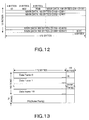
- FIG. 12 is a schematic view representing a data frame structure generated in the data frame generator R01.
- the data frame is constituted of a sector identifier (ID), an ID error detection code (IED), auxiliary data (RSB), main data (contents data being main information), and an error detection code (EDC).
- ID sector identifier
- IED ID error detection code
- RSB auxiliary data
- main data contents data being main information
- EDC error detection code
- FIG. 13 is a schematic view representing an ECC block, to which the error correcting outer parity PO and inner parity PI generated are added, outputted from the PO/PI generator R051.
- the error correcting parities PO and PI are added to a data block which is composed of 16 sets of the data frames shown in FIG. 12 gathered.
- FIG. 14 is a schematic view representing an ECC block in which the error correcting outer parity PO is dispersed, outputted from the PO interleave unit R06.
- FIG. 15 a schematic view representing a physical sector in a state in which the media mark signal (MM) is incorporated, outputted from the media mark (MM) replacing unit R14.
- Themediamarkmodulation signal (MM) is dispersed in a plurality of physical sectors to thereby improve the possibility of reproducing the main information without greatly degrading the ability of correcting an error in the main information.
- the dispersion of the media mark modulation signal leads to improvement in confidentiality thereof.
- the pattern selected as the media mark modulation signal is limited to the pattern which causes no modulation rule violation in the main information.
- the embedding area of the media mark modulation signal is increased to accommodate the number of the patterns of the media mark modulation signal, thus causing a possibility of increasing the area which will be incorrectly reproduced in demodulating the main information.
- FIGS. 15A to 16E are schematic views representing data streams changed in a conversion process different from that in FIG. 9A to 9D.
- Data words A to D shown in FIG. 16A are code-converted into code words A to D shown in FIG. 16B, and further converted into code words A' to D' shown in FIG. 16C by performance of the connection rule processing. Then, the code words A' and D' adjacent to a portion replaced with the media mark modulation signal are inversely converted into code words A and D (FIG. 16D). The processing so far is the same as that in FIG. 9A to 9D.
- the code words B' and C' are replaced with the code word MM of the media mark modulation signal to generate code word streams A", MM, D" shown in FIG. 16E, whereby the media mark modulation signal is embedded in the main information modulation signal.
- the code word streams A and D are converted into the codeword streams A" and D" , respectively.
- the code word streams A" and D" after conversion are decided depending on the combination of the code word MM of the media mark modulation signal and the core word streams A and D. This is for preventing occurrence of modulation rule violation in the main information.
- the code word streams A" and D" are to be returned to the data words A and D in demodulating the main information in a similar manner to that for the code word streams A and D. For example, assuming that a data word D modulated in a state of 0 is regarded as a code word D, the data word D modulated in a state of 1 or 2 can be regarded as the code word D". It should be noted that the procedure of generating the media mark modulation signal MM is the same as that in the case of FIG. 9A to 9D.
- code words B and C may have error data on the main information demodulation side as in FIG. 9A to 9D, and the code words A" and D" will be correctly demodulated if no defect or the like occurs.
- FIGS. 17A to 17C are schematic views representing data streams shifting when no connection rule processing is performed for the data word connected to the place which will be replaced with the media mark modulation signal.
- the procedure of generating the media mark modulation signal is the same as that in FIG. 9A to 9D.
- FIGS. 18A to 18D after the performance of replacement with the media mark modulation signal (MM) by the processing shown in FIGS. 17A to 17C, the code word streams A and D are converted into code word streams A" and D" , respectively.
- the code word streams A" and D" after conversion are decided, in the similar manner to that in FIG. 16E, depending on the combination of the code word MM of the media mark modulation signal and the code word streams A and D.
- FIG. 19 is a block diagram representing a configuration example of a demodulator which demodulates a main information modulation signal with a media mark modulation signal embedded therein.
- a channel bit stream of the main information modulation signal with the media mark modulation signal embedded therein is inputted into a code separatorwhere the code convers ion based on the connection rule is canceled to generate a code word (a kind of inverse conversion) .
- the code word is inputted into a decode table unit where the code conversion based on the code conversion table as shown in FIG. 3A is canceled to generate a data word.
- the main information modulation signal with the media mark modulation signal embedded therein is subjected to demodulation processing. It should be noted that the processing in the decode table unit, selected table information (information on the selection of a table, specifically, state information) is used which is outputted from the code separator.
- the data word is inputted into a first error correction unit (ECC(1)) and subjected to error correction processing, whereby the data word of the main information before embedding of (replacement with) the media mark modulation signal is reproduced.
- ECC(1) error correction unit
- the media mark embedded in the main information is similar to error data due to a general defect in the viewpoint of the error correction processing.
- the channel bit stream of the main information modulation signal with the media mark modulation signal (MM) embedded therein is also inputted into a media mark demodulator where the media mark modulation signal is demodulated.
- media mark embedded positional information (MM Position) is inputted so that only an area of the channel bit indicated by this information becomes demodulation subject.
- a media mark demodulation signal thus intermittently outputted is inputted into a media mark correcting unit (ECC(2)) and gathered here.
- ECC(2) media mark correcting unit
- an error flag can be used which is generated in demodulating the media mark modulation signal. More specifically, when a pattern that is not normally used appears in demodulating the media mark modulation signal, it can be judged that an error occurs in the media mark modulation signal, and an error flag can be provided.
- the use of a method, which is different from the modulation method for the main information, for the modulation method for the media mark enables improvement in reliability of the error flag.
- a modulation pattern different from that for the main information is used for the media mark modulation signal, so that even when the media mark modulation signal is demodulated by the demodulator for the main information and modulated again by the main information modulator, the resultant media mark signal is prevented from being returned to the original media mark signal (inverse conversion is impossible).
- a modulation method with a high conversion redundancy using a larger number of bits than the number of bits normally required are examples of the media mark modulation method.
- FIG. 20 is a diagram illustrating an example of a procedure of encoding contents in a read-only optical disk.
- a disk manufacturer receives contents 300 and a title key (Kt) 301 from a copyright holder 100.
- the disk manufacturer also receives a media key (Km) 303 for use in encoding the contents and a media key block (MKB) generated by a device key set from a copyright protection (CP) management organization 101.
- Kt title key
- Km media key
- MKB media key block
- An encoding processing unit 307 encodes the contents using the title key (Kt) as an encryption key to generate encoded contents (Enc-Contents).
- An encoding processing unit 306 encodes the title key (Kt) using a media specific key (Kmu) to generate an encoded title key (Enc-Kt).
- the media specific key (Kmu) used in this event is generated by mixing a volume identifier (Volume ID) 311 and the media key (Km) 303 in a key generator 3053.
- a confidential information writing unit 312 embeds the volume identifier (Volume ID) as confidential information in proprietary data (RP-data) whose ownership is possessed by the disk manufacturer to generate embedded proprietary data (RP-data+MM).
- the modulator illustrated in the above-described embodiment can be applied.
- the proprietary data (RP-data) as the main information and the volume identifier (Volume ID) as the confidential information are modulated respectively, so that the confidential information is embedded in the main information.
- a master disk is manufactured on which the media key block (MKB), the embedded proprietary data (RP-data+MM), the encoded title key (Enc-Kt), and the encoded contents (Enc-Contents) generated are recorded.
- This master disk is used to manufacture read-only media on which encoded contents are recorded.
- FIG. 21 is a diagram illustrating a procedure of reproducing the read-only media manufactured by the procedure shown in FIG. 20. Such a case is illustrated that the recording medium is reproduced by a data reading drive connected to an AV (Audio/Video) decoder board mounted on a computer.
- AV Audio/Video
- the data reading drive reads from the recording medium D the media key block (MKB), the embedded proprietary data (RP-data+MM), the encoded title key (Enc-Kt), and the encoded contents (Enc-Contents).
- MKB media key block
- RP-data+MM embedded proprietary data
- Enc-Kt encoded title key
- Enc-Contents the encoded contents
- the media key block (MKB) and the embedded proprietary data (RP-data+MM) are outputted from the data reading drive to the AV decoder board.
- the signal outputted in this event is encoded on the drive side by a time-limited key and decoded on the AV decoder board side to thereby prevent unauthorized extraction on a transmission line.
- the encoded title key (Enc-Kt) and the encoded contents (Enc-Contents) are transmitted from the data reading drive to the AV decoder board as they are without encoding.
- the embedded proprietary data (RP-data+MM) is inputted into a confidential information detector 330 and separated into the proprietary data (RP-data) and the volume identifier (Volume ID) being confidential information.
- the decoding processing, utilizing the demodulator, illustrated in the above-described embodiment can be applied.
- the proprietary data (RP-data) as the main information and the volume identifier (Volume ID) as the confidential information are demodulated respectively, so that the main information and the confidential information are separated.
- the media key (Km) is extracted by inputting the media key block (MKB) received and the device key set 320 into an MKB processing unit 321.
- the media key (Km) and the volume identifier (Volume ID) are mixed in a key generator 322 to generate the media specific key (Kmu).
- the encoded title key (Enc-Kt) is decoded using the media specific key (Kmu) in a decoding unit 323 to detect the title key (Kt) .
- the encoded contents (Enc-Contents) are decoded by a decoding unit 308 using the title key (Kt) to reproduce contents in a plain text.
- the volume identifier (Volume ID) embedded as confidential information in the proprietary data (RP-data) is recorded on the recording medium. Therefore, even if all the data on the recording medium is copied, it is difficult to decode the encoded contents on a medium which has been illegally copied unless the volume identifier (Volume ID) can be separated. Since the volume identifier (Volume ID) is detected only in the drive and transmitted to the authenticated AV decoder board, extraction of the volume identifier (Volume ID) during transmission is difficult, so that the copyright protection can be realized.
- the modulator is appliedto recording processing in a read/write optical disk.
- the processing can be divided to that of manufacturing the optical disk and that of recording by a user.
- FIG. 22 illustrates processing contents in manufacturing a read/write optical disk.
- the disk manufacturer receives a media key (Km) for use in encoding contents and a media key block (MKB) generated by a device key set from a copyright protection (CP) management organization.
- Km media key
- MKB media key block
- a confidential information writing unit 312 embeds a media mark (MM) as confidential information in proprietary data (RP-data) to generate embedded proprietary data (RP-data+MM).
- RP-data proprietary data
- RP-data+MM embedded proprietary data
- the modulation and replacement processing illustrated in the above-described embodiment can be applied.
- the proprietary data (RP-data) as the main information and the media mark (MM) as the confidential information are modulated respectively, so that the confidential information is embedded in the main information.
- the disk manufacturer also prepares a media identifier (M-ID: Media ID) which uniquely identifies the recording medium.
- M-ID Media ID
- a read/write optical disk is manufactured on which the media key block (MKB), the embedded proprietary data (RP-data+MM), and the media identifier (Media ID) are recorded.
- MKB media key block
- RP-data+MM embedded proprietary data
- Media ID media identifier
- FIG. 23 is a diagram illustrating a procedure of encoding contents and recording the resultant contents on a read/write medium having a configuration such as shown in FIG. 22. Such a case is illustrated that recording onto the recording medium is performed by a data writing drive connected to an AV (Audio/Video) encoder board mounted on a computer.
- AV Audio/Video
- the drive reads from the recording medium the media key block (MKB), the media identifier (M-ID), and the embedded proprietary data (RP-data+MM).
- MKB media key block
- M-ID media identifier
- RP-data+MM embedded proprietary data
- the embedded proprietary data (RP-data+MM) is inputted into a confidential information detector 2310 and separated into the proprietary data (RP-data) and the media mark (MM) being confidential information.
- the demodulator illustrated in the above-described embodiment can be applied.
- the proprietary data (RP-data) as the main information and the media mark (MM) as the confidential information are demodulated respectively, so that the main information and the confidential information are separated.
- the media identifier (M-ID) and the media mark (MM) are mixed in mixed 2312 to generate a media mark identifier (MM-ID).
- the media key block (MKB) and the media mark identifier (MM-ID) are outputted from the drive to the AV encoder board.
- the signal outputted in this event is encoded on the drive side by a time-limited key and decoded on the AV encoder board side to thereby prevent unauthorized extraction on a transmission line.
- the media key (Km) is extracted by inputting the media key block (MKB) received and a device key set into an MKB processing unit 2314.
- the media key (Km) and the media mark identifier (MM-ID) are mixed in a key generator 2316 to generate a media specific key (Kmu).
- the contents are encoded in encoder 2318 using the title key (Kt) to generate encoded contents (Enc-Contents), which are record onto the recording medium.
- the title key (Kt) is encoded in encoder 2320 using the media specific key (Kmu) to generate an encoded title key (Enc-Kt), which is recorded onto the recording medium.
- FIG. 24 illustrates a procedure of reading and decoding the encoded contents recorded in the configuration in FIG. 23 to reproduce contents in a plain text. Such a case is illustrated that recording onto the recording medium is performed by a data writing drive connected to an AV (Audio/Video) decoder board mounted on a computer.
- AV Audio/Video
- the drive reads from the recording medium the media key block (MKB), the media identifier (M-ID), the embedded proprietary data (RP-data+MM), the encoded title key (Enc-Kt), and the encoded contents (Enc-Contents).
- MKB media key block
- M-ID media identifier
- RP-data+MM embedded proprietary data
- Enc-Kt encoded title key
- Enc-Contents the encoded contents
- the embedded proprietary data (RP-data+MM) is inputted into a confidential information detector 2410 and separated into the proprietary data (RP-data) and the media mark (MM) being the confidential information.
- the demodulator illustrated in the above-described embodiment can be applied.
- the media identifier (M-ID) and the media mark (MM) are mixed in mixer 2412 to generate the media mark identifier (MM-ID).
- the media key block (MKB) and the media mark identifier (MM-ID) are outputted from the drive to the AV decoder board.
- the signal outputted in this event is encoded by encoders 2414 and 2416 on the drive side by a time-limited key and decoded by decoders 2418 and 2420 on the AV decoder board side to thereby prevent unauthorized extraction on a transmission line.
- the encoded title key (Enc-Kt) and the encoded contents (Enc-Contents) are transmitted from the data reading drive to the AV decoder board as they are without encoding.
- the media key (Km) is extracted by inputting the media key block (MKB) received and a device key set into an MKB processing unit 2422.
- the media key (Km) and the media mark identifier (MM-ID) are mixed in a key generator 2424 to generate the media specific key (Kmu).
- the encoded title key (Enc-Kt) is decoded using the media specific key (Kmu) in a decoding unit 2426 to detect the title key (Kt).
- the encoded contents (Enc-Contents) are decoded using the title key (Kt) in a decoding unit 2428 to reproduce contents in a plain text.
- the media mark (MM) embedded as confidential information in the proprietary data (RP-data)
- RP-data proprietary data
- the media mark (MM) is recorded on the recording medium. Therefore, even if all the data on the recording medium is copied, it is difficult to decode the encoded contents on a medium which has been illegally copied unless the media mark (MM) can be separated. Since the media mark (MM) can be detected and processed only in the drive, it is possible to ensure the confidentiality of the media mark (MM) and realize the copyright protection.
- FIG. 25 is a block diagram, corresponding to FIG. 2, representing details of an internal configuration of the modulator R071 shown in FIG. 1, and illustrating a second embodiment of the present invention.
- a code word outputted from a code table unit 21 is inputted into a media mark modulator 24 and used in modulating a media mark (MM).
- This information is used for control of a state in modulating the media mark. Further, it becomes possible to process together the media mark to be embedded and code words before and after the mark. More specifically, by applying the connection rule between the media mark and the code words before and after the mark, propagation of an error caused by embedding a media mark signal (MM) can be reduced.
- MM media mark signal
- FIG. 26 is a block diagram, corresponding to FIG. 2, representing details of an internal configuration of the modulator R071 shown in FIG. 1, and illustrating a third embodiment.
- Processing in a code table unit 31 and processing in a code connector 33x are performed in sequence.
- a connected code word signal which has undergone the connection rule processing in the code connector 33x is inputted into a media mark controller 36.
- the media mark controller 36 cancels the connection rule processing in the connected code word.
- the code word whose connection rule processing has been cancelled is inputted into a media mark modulator 34 and processed together with the media mark signal.
- the media mark signal and the code words before and after the signal are processed in the media mark modulator 34 under consideration of the connection rule.
- the connected code word signal outputted from the DSV controller 35 is inputted into the media mark controller 36. This is for allowing the media mark controller 36 to detect the number of "1s" of original channel bits in an area into which the media mark is inserted and to control the number of "1s" of channel bits of the media mark signal to be inserted equal to the above number. This results in prevention of deterioration in the DC-component suppress characteristics which may be caused by embedding the media mark in a signal after the processing in the DSV controller 35.
- FIG. 27 is a block diagram, corresponding to FIG. 2, representing details of an internal configuration of the modulator R071 shown in FIG. 1, and illustrating a fourth embodiment.
- a code table unit 41 for main information and a media mark modulator 44 operate in parallel to generate a code word and a media mark modulation signal respectively.
- a state register 42 in this event is common to the code table unit 41 for the main information and the media mark modulator 44 and is switched between the two by the switch S1. This switching is performed in conjunction with switching of output between the code word and the media markmodulation signal by a switch S2 , and the code table unit 41 and the media mark modulator 44 are alternately operated in accordance with whether replacement with the media mark signal is performed (to cause the media mark modulator 44 to operate at a position of a symbol to be replaced with the media mark signal).
- the channel bit stream outputted from the switch S2 is inputted into a DSV controller 45 and used for control of the state register 42 by the DSV controller 45.
- the DSV controller 45 monitors the cumulative DC components of the channel bit stream and changes the state indicated by the state register 42 in accordance with the monitoring result.
- the code table unit 41 and the media mark modulator 44 operate in accordance with the change of this state, whereby DSV is controlled.
- FIG. 28 relates to a fifth embodiment of the present invention and illustrates a case in which an MM modulator is incorporated in the 8-16 modulation method shown in DVD standard.
- the modulation method shown in the DVD standard will be described.
- four states are prepared for each symbol, and a code table unit is configured such as to prevent modulation rule violation from occurring in connection between the symbols.
- Four additional states are provided for a part of data word and used for the DSV control.
- the states of the synchronization signals also can be selected to perform DSV control, and both of them are used to perform the DSV control.
- a DSV controllable data word and synchronization signal are given, a plurality of conversion patterns are stored in a memory respectively to configure a plurality of channel bit streams and DSV detection is performed for them independently.
- FIG. 28 is an embodiment corresponding to themodulationmethod of such a DVD standard.
- a code table unit 2810 modulates data words B(t) in accordance with the state indicated by state register 2812 to generate channel bits.
- the modulations are conducted in parallel based on two tables (main table and substitution table). In modulation results respectively based on the two tables, a result having a smaller DSV is selected and outputted to control DSV.
- the main table defines modulation codes of 16 bits in accordance with data words from 0 to 256 of decimal representation and four states, respectively.
- the substitution table defines modulation codes of 16 bits in accordance with data words from 0 to 87 of decimal representation and four states, respectively.
- the code table unit 2810 modulates datawords B (t) in accordance with the state represented by the state resistor 2812 using the two tables. If data words are in the range from 0 to 87, the code table unit 2810 outputs the channel bits modulated by the main table to the memory a (2814), and the channel bits modulated by the substitution table to the memory b (2816). On the other hand, if data words are in the range from 88 to 255, the code table unit 2810 outputs the channel bits modulated by the main table to both of the memory a (2814) and b (2816). In other words, if data words are in the range from 88 to 256, modulation by the substitution table and selection of modulation results are not conducted.
- the memory a (2814) and b (2816) store inputted values.
- the respective DSVs of the channel bits (a) and (b) thus outputted are detected by DSV detectors 2818 and 2820 respectively, and the detection results are inputted into the DSV controller 2822. Based on the detection results, the DSV controller 2822 controls the output of the state register 2812 by the switch (as shown by the dotted line) to thereby perform the DSV control.
- the DVS controller 2822 also controls switch S (a) to selectively feed the output of memories 2814 and 2816 to a transition bit counter 2824 and delay unit 2828.
- the transition bit counter 2824 counts the number of "1s" of the channel bit in a media mark signal (MM) embedded area and judges whether the total thereof is even or odd, and outputs a state signal to the media markmodulator 2826 in accordance with the result.
- the media mark modulator 2826 into which the state signal for modulating the media mark is inputted together with the media mark (MM), matches the even/odd parity of the total of "1s" in the media mark modulation pattern with the even/odd parity of the total of "1s” in the channel bit before replacement.
- Such processing is performed to prevent the deterioration in the DSV characteristics due to the embedding of the media mark.
- the polarity at the final stage of the media mark modulation pattern described with FIG. 8 can be matched with the polarity when media mark embedding is not performed. Note that the difference in DSV in an MM pattern area causes a slight variation in DSV as a whole stream, which can be neglected.
- the switch S (b) switches between the data channel bit stream of the main information, which passes through the delay unit 2828 and the channel bit of the media mark modulation signal (MM Code Word) (in other words, replacement with the media mark modulation signal is performed), to thereby generate a data channel bit stream.
- MM Code Word media mark modulation signal
- Embodiments of the present invention can be expanded and modified without being limited to the above-described embodiments, and such expanded and modified embodiments are also included in the technical scope of the present invention.
Abstract
Description
Claims (11)
- A modulator, comprising:a main information converter configured to code-convert main information by a first modulation method;a specific information converter configured to code-convert specific information by a second modulation method different from the first modulation method;a replacement unit configured to replace a part of the code-converted main information with the code-converted specific information; anda direct-current component suppressing unit configured to suppress direct-current components of the replacedmain information.
- The modulator as set forth in claim 1,
wherein the main information is constituted of channel bits of a predetermined length. - The modulator as set forth in claim 2,
wherein the main information is code-converted based on a main information conversion table showing channel bits of the main information before and after the code-conversion. - The modulator as set forth in claim 2, further comprising:a connection rule processing unit configured to code-convert the code-converted main information based on a connection rule table showing combinations of adjacent channel bits before and after the processing.
- The modulator as set forth in claim 4,
wherein said connection rule processing unit does not code-converts a channel bit of the code-converted main information adjacent to a channel bit to be replaced with the specific information. - The modulator as set forth in claim 4, further comprising:a connection rule inverting unit configured to return a channel bit of the code-converted main information based on the connection rule table to a state before the connection rule processing, and the channel bit being adjacent to the channel bit replaced with the specific information.
- The modulator as set forth in claim 1,
wherein the main information is constituted of channel bits of a predetermined length, and the main information is code-converted based on state information defined by a channel bit immediately before a channel bit to be code-converted. - The modulator as set forth in claim 1,
wherein the main information includes proprietary data being a subject of ownership and encoded contents, and the specific information constitutes a part of an encryption key for decoding the encoded contents. - A modulation method comprising:code-converting main information by a first modulation method;code-converting specific information by a second modulation method different from the first modulation method;replacing a part of the code-converted main information with the code-converted specific information to output a channel bit stream; andsuppressing direct-current components of the replaced main information.
- The method of claim 9 wherein the suppressing direct-current components includes calculating a digital sum value of the channel bits stream.
- A method of manufacturing an optical recordable medium comprising:generating encoded master key data;generating main information including proprietary data;generating confidential information different from said proprietary data;code-converting said main information by a first modulation method;code-converting said specific information by a second modulation method different from the first modulation method;replacing a part of the code-converted main information with the code-converted specific information to output a channel bit stream; andsuppressing direct-current components of the replaced main information; andembedding said encoded master key data, and said suppressed channel bit stream on said optical recordable medium.
Applications Claiming Priority (4)
| Application Number | Priority Date | Filing Date | Title |
|---|---|---|---|
| JP2004134666 | 2004-04-28 | ||
| JP2004134666A JP4220431B2 (en) | 2004-04-28 | 2004-04-28 | Modulation device, recording medium recording device, and recording medium |
| JP2005018590A JP4557729B2 (en) | 2005-01-26 | 2005-01-26 | Modulator |
| JP2005018590 | 2005-01-26 |
Publications (2)
| Publication Number | Publication Date |
|---|---|
| EP1592011A2 true EP1592011A2 (en) | 2005-11-02 |
| EP1592011A3 EP1592011A3 (en) | 2007-11-07 |
Family
ID=34938818
Family Applications (1)
| Application Number | Title | Priority Date | Filing Date |
|---|---|---|---|
| EP05101451A Withdrawn EP1592011A3 (en) | 2004-04-28 | 2005-02-25 | Modulator, modulation method, and method of manufacturing an optical recordable medium with enhanced security for confidential information |
Country Status (4)
| Country | Link |
|---|---|
| US (1) | US7091887B2 (en) |
| EP (1) | EP1592011A3 (en) |
| KR (1) | KR100597987B1 (en) |
| TW (1) | TW200539150A (en) |
Families Citing this family (8)
| Publication number | Priority date | Publication date | Assignee | Title |
|---|---|---|---|---|
| US6917313B1 (en) | 2002-01-16 | 2005-07-12 | Marvell International Ltd. | DC-free codes |
| US7886158B2 (en) * | 2005-09-08 | 2011-02-08 | Hitachi, Ltd. | System and method for remote copy of encrypted data |
| US8571188B2 (en) | 2006-12-15 | 2013-10-29 | Qualcomm Incorporated | Method and device for secure phone banking |
| US8290162B2 (en) | 2006-12-15 | 2012-10-16 | Qualcomm Incorporated | Combinational combiner cryptographic method and apparatus |
| US8055903B2 (en) | 2007-02-15 | 2011-11-08 | Avaya Inc. | Signal watermarking in the presence of encryption |
| EP3518128B1 (en) * | 2011-03-30 | 2021-04-28 | Irdeto B.V. | Enabling a software application to be executed on a hardware device |
| US9197407B2 (en) * | 2011-07-19 | 2015-11-24 | Cyberlink Corp. | Method and system for providing secret-less application framework |
| KR102491708B1 (en) * | 2020-12-15 | 2023-01-26 | 주식회사 엘지유플러스 | Method and apparatus for exchanging encryption information |
Citations (2)
| Publication number | Priority date | Publication date | Assignee | Title |
|---|---|---|---|---|
| US20030061500A1 (en) * | 2001-09-27 | 2003-03-27 | Hideki Mimura | Signal processing method and device, and recording medium |
| US20030070082A1 (en) * | 2001-10-10 | 2003-04-10 | Hideki Nimura | Method and apparatus for recording information including secret information and method and apparatus for reproduction thereof |
Family Cites Families (4)
| Publication number | Priority date | Publication date | Assignee | Title |
|---|---|---|---|---|
| JPH11238305A (en) | 1998-02-23 | 1999-08-31 | Sony Corp | Data processing method and data recording and reproducing device |
| JP4047480B2 (en) | 1998-03-17 | 2008-02-13 | 株式会社東芝 | Recording medium, recording medium creation apparatus, and data reproduction apparatus |
| JP2003122637A (en) | 2001-10-10 | 2003-04-25 | Toshiba Corp | Information recording method and device, and reproducing method and device accompanied with secrecy information |
| JP3878542B2 (en) * | 2002-11-29 | 2007-02-07 | 株式会社東芝 | Recording device |
-
2005
- 2005-02-10 US US11/056,349 patent/US7091887B2/en not_active Expired - Fee Related
- 2005-02-18 TW TW094104916A patent/TW200539150A/en unknown
- 2005-02-24 KR KR1020050015291A patent/KR100597987B1/en not_active IP Right Cessation
- 2005-02-25 EP EP05101451A patent/EP1592011A3/en not_active Withdrawn
Patent Citations (2)
| Publication number | Priority date | Publication date | Assignee | Title |
|---|---|---|---|---|
| US20030061500A1 (en) * | 2001-09-27 | 2003-03-27 | Hideki Mimura | Signal processing method and device, and recording medium |
| US20030070082A1 (en) * | 2001-10-10 | 2003-04-10 | Hideki Nimura | Method and apparatus for recording information including secret information and method and apparatus for reproduction thereof |
Non-Patent Citations (1)
| Title |
|---|
| SCHOUHAMER IMMINK K A: "EFMPLUS: THE CODING FORMAT OF THE MULTIMEDIA COMPACT DISC" IEEE TRANSACTIONS ON CONSUMER ELECTRONICS, IEEE SERVICE CENTER, NEW YORK, NY, US, vol. 41, no. 3, 1 August 1995 (1995-08-01), pages 491-497, XP000539497 ISSN: 0098-3063 * |
Also Published As
| Publication number | Publication date |
|---|---|
| KR20060043175A (en) | 2006-05-15 |
| TW200539150A (en) | 2005-12-01 |
| KR100597987B1 (en) | 2006-07-13 |
| US7091887B2 (en) | 2006-08-15 |
| EP1592011A3 (en) | 2007-11-07 |
| US20050244003A1 (en) | 2005-11-03 |
Similar Documents
| Publication | Publication Date | Title |
|---|---|---|
| US6425098B1 (en) | Prevention of disk piracy | |
| US7091887B2 (en) | Modulator, modulation method, and method of manufacturing an optical recordable medium with enhanced security for confidential information | |
| JP3467964B2 (en) | Data recording device and method, data reproducing device and method, recording medium, and data transmission method | |
| JPH09288864A (en) | Digital data duplicate inhibiting method | |
| WO2001093265A3 (en) | Secure digital video disk and player | |
| JP4023849B2 (en) | Data recording method and apparatus, and data reproducing method and apparatus | |
| US7233267B2 (en) | Digital data recording medium, recording method, recording device, reproduction method, and reproduction device | |
| JPH11238305A (en) | Data processing method and data recording and reproducing device | |
| US20050015616A1 (en) | Copy protected mastering system | |
| EP1418584A1 (en) | Digital data recording medium, recording method, recording device, reproduction method, and reproduction device | |
| JP4220431B2 (en) | Modulation device, recording medium recording device, and recording medium | |
| JP4557729B2 (en) | Modulator | |
| US7203141B2 (en) | Recording medium, recording method, recording device, and reproduction method and reproducer | |
| US20050254387A1 (en) | Recording medium processing device | |
| US20060285465A1 (en) | Information recording processing device, information reproduction processing device, information recording medium and method, and computer program | |
| JP3953007B2 (en) | Information recording processing apparatus, information reproducing processing apparatus, information recording medium and method, and computer program | |
| JP4140485B2 (en) | Information recording processing apparatus, information reproducing processing apparatus, information recording medium and method, and computer program | |
| WO2000062293A1 (en) | Copy protection signature for compact disks | |
| JP3941764B2 (en) | Information recording processing apparatus, information reproducing processing apparatus, information recording medium and method, and computer program | |
| US20060098541A1 (en) | Recorder, recording method, reproducer, reproducing method, and recording medium | |
| JP2005071490A (en) | Information recording device, information reproducing device, information recording medium and method, and computer program | |
| JP2005085400A (en) | Data recording medium, method and device for recording data, method and device for reproducing data, and method for transmitting/receiving data | |
| JP2003338126A (en) | Recording medium, recording method, recorder, reproduction method, reproduction device, transmission method, and transmitter for digital data | |
| KR20050023354A (en) | Recorder, recording method, reproducer, reproducing method, and recording medium | |
| JP2006197606A (en) | Signal processing method and apparatus, signal reproducing method and apparatus, and recording medium |
Legal Events
| Date | Code | Title | Description |
|---|---|---|---|
| PUAI | Public reference made under article 153(3) epc to a published international application that has entered the european phase |
Free format text: ORIGINAL CODE: 0009012 |
|
| 17P | Request for examination filed |
Effective date: 20050228 |
|
| AK | Designated contracting states |
Kind code of ref document: A2 Designated state(s): AT BE BG CH CY CZ DE DK EE ES FI FR GB GR HU IE IS IT LI LT LU MC NL PL PT RO SE SI SK TR |
|
| AX | Request for extension of the european patent |
Extension state: AL BA HR LV MK YU |
|
| PUAL | Search report despatched |
Free format text: ORIGINAL CODE: 0009013 |
|
| AK | Designated contracting states |
Kind code of ref document: A3 Designated state(s): AT BE BG CH CY CZ DE DK EE ES FI FR GB GR HU IE IS IT LI LT LU MC NL PL PT RO SE SI SK TR |
|
| AX | Request for extension of the european patent |
Extension state: AL BA HR LV MK YU |
|
| RIC1 | Information provided on ipc code assigned before grant |
Ipc: G11B 20/14 20060101ALI20071003BHEP Ipc: G11B 20/00 20060101AFI20050909BHEP |
|
| 17Q | First examination report despatched |
Effective date: 20080131 |
|
| AKX | Designation fees paid |
Designated state(s): DE FR GB |
|
| STAA | Information on the status of an ep patent application or granted ep patent |
Free format text: STATUS: THE APPLICATION IS DEEMED TO BE WITHDRAWN |
|
| 18D | Application deemed to be withdrawn |
Effective date: 20090609 |