EP1593033B1 - Tape storage emulation for open systems environments - Google Patents
Tape storage emulation for open systems environments Download PDFInfo
- Publication number
- EP1593033B1 EP1593033B1 EP04708242A EP04708242A EP1593033B1 EP 1593033 B1 EP1593033 B1 EP 1593033B1 EP 04708242 A EP04708242 A EP 04708242A EP 04708242 A EP04708242 A EP 04708242A EP 1593033 B1 EP1593033 B1 EP 1593033B1
- Authority
- EP
- European Patent Office
- Prior art keywords
- tape
- data
- server
- command
- commands
- Prior art date
- Legal status (The legal status is an assumption and is not a legal conclusion. Google has not performed a legal analysis and makes no representation as to the accuracy of the status listed.)
- Expired - Lifetime
Links
- 239000003999 initiator Substances 0.000 claims abstract description 27
- 238000000034 method Methods 0.000 claims abstract description 23
- 238000004590 computer program Methods 0.000 claims abstract description 3
- 239000000835 fiber Substances 0.000 claims description 31
- 230000008676 import Effects 0.000 claims description 8
- 230000005540 biological transmission Effects 0.000 claims description 5
- 238000011084 recovery Methods 0.000 description 14
- 239000004744 fabric Substances 0.000 description 12
- 238000007726 management method Methods 0.000 description 12
- 230000004044 response Effects 0.000 description 12
- 230000006870 function Effects 0.000 description 11
- 238000012384 transportation and delivery Methods 0.000 description 10
- 238000003491 array Methods 0.000 description 9
- 238000010586 diagram Methods 0.000 description 9
- 238000012546 transfer Methods 0.000 description 9
- 238000013459 approach Methods 0.000 description 6
- 239000000872 buffer Substances 0.000 description 6
- 230000008569 process Effects 0.000 description 6
- 230000009471 action Effects 0.000 description 5
- 238000005516 engineering process Methods 0.000 description 4
- 238000004891 communication Methods 0.000 description 3
- 230000008901 benefit Effects 0.000 description 2
- 238000013500 data storage Methods 0.000 description 2
- 238000013507 mapping Methods 0.000 description 2
- 230000003287 optical effect Effects 0.000 description 2
- 230000000630 rising effect Effects 0.000 description 2
- 230000005465 channeling Effects 0.000 description 1
- 238000012790 confirmation Methods 0.000 description 1
- 238000013461 design Methods 0.000 description 1
- 238000001514 detection method Methods 0.000 description 1
- 230000009977 dual effect Effects 0.000 description 1
- 238000009432 framing Methods 0.000 description 1
- 230000007246 mechanism Effects 0.000 description 1
- 230000008520 organization Effects 0.000 description 1
- 230000002085 persistent effect Effects 0.000 description 1
- 230000011664 signaling Effects 0.000 description 1
Images


Classifications
-
- G—PHYSICS
- G06—COMPUTING; CALCULATING OR COUNTING
- G06F—ELECTRIC DIGITAL DATA PROCESSING
- G06F3/00—Input arrangements for transferring data to be processed into a form capable of being handled by the computer; Output arrangements for transferring data from processing unit to output unit, e.g. interface arrangements
- G06F3/06—Digital input from, or digital output to, record carriers, e.g. RAID, emulated record carriers or networked record carriers
- G06F3/0601—Interfaces specially adapted for storage systems
- G06F3/0602—Interfaces specially adapted for storage systems specifically adapted to achieve a particular effect
- G06F3/0604—Improving or facilitating administration, e.g. storage management
- G06F3/0607—Improving or facilitating administration, e.g. storage management by facilitating the process of upgrading existing storage systems, e.g. for improving compatibility between host and storage device
-
- G—PHYSICS
- G06—COMPUTING; CALCULATING OR COUNTING
- G06F—ELECTRIC DIGITAL DATA PROCESSING
- G06F11/00—Error detection; Error correction; Monitoring
- G06F11/07—Responding to the occurrence of a fault, e.g. fault tolerance
- G06F11/14—Error detection or correction of the data by redundancy in operation
- G06F11/1402—Saving, restoring, recovering or retrying
- G06F11/1446—Point-in-time backing up or restoration of persistent data
- G06F11/1458—Management of the backup or restore process
-
- G—PHYSICS
- G06—COMPUTING; CALCULATING OR COUNTING
- G06F—ELECTRIC DIGITAL DATA PROCESSING
- G06F3/00—Input arrangements for transferring data to be processed into a form capable of being handled by the computer; Output arrangements for transferring data from processing unit to output unit, e.g. interface arrangements
- G06F3/06—Digital input from, or digital output to, record carriers, e.g. RAID, emulated record carriers or networked record carriers
- G06F3/0601—Interfaces specially adapted for storage systems
- G06F3/0602—Interfaces specially adapted for storage systems specifically adapted to achieve a particular effect
- G06F3/0604—Improving or facilitating administration, e.g. storage management
-
- G—PHYSICS
- G06—COMPUTING; CALCULATING OR COUNTING
- G06F—ELECTRIC DIGITAL DATA PROCESSING
- G06F3/00—Input arrangements for transferring data to be processed into a form capable of being handled by the computer; Output arrangements for transferring data from processing unit to output unit, e.g. interface arrangements
- G06F3/06—Digital input from, or digital output to, record carriers, e.g. RAID, emulated record carriers or networked record carriers
- G06F3/0601—Interfaces specially adapted for storage systems
- G06F3/0628—Interfaces specially adapted for storage systems making use of a particular technique
- G06F3/0662—Virtualisation aspects
- G06F3/0664—Virtualisation aspects at device level, e.g. emulation of a storage device or system
-
- G—PHYSICS
- G06—COMPUTING; CALCULATING OR COUNTING
- G06F—ELECTRIC DIGITAL DATA PROCESSING
- G06F3/00—Input arrangements for transferring data to be processed into a form capable of being handled by the computer; Output arrangements for transferring data from processing unit to output unit, e.g. interface arrangements
- G06F3/06—Digital input from, or digital output to, record carriers, e.g. RAID, emulated record carriers or networked record carriers
- G06F3/0601—Interfaces specially adapted for storage systems
- G06F3/0668—Interfaces specially adapted for storage systems adopting a particular infrastructure
- G06F3/0671—In-line storage system
- G06F3/0683—Plurality of storage devices
- G06F3/0689—Disk arrays, e.g. RAID, JBOD
-
- G—PHYSICS
- G06—COMPUTING; CALCULATING OR COUNTING
- G06F—ELECTRIC DIGITAL DATA PROCESSING
- G06F11/00—Error detection; Error correction; Monitoring
- G06F11/07—Responding to the occurrence of a fault, e.g. fault tolerance
- G06F11/14—Error detection or correction of the data by redundancy in operation
- G06F11/1402—Saving, restoring, recovering or retrying
- G06F11/1446—Point-in-time backing up or restoration of persistent data
- G06F11/1458—Management of the backup or restore process
- G06F11/1464—Management of the backup or restore process for networked environments
-
- G—PHYSICS
- G06—COMPUTING; CALCULATING OR COUNTING
- G06F—ELECTRIC DIGITAL DATA PROCESSING
- G06F3/00—Input arrangements for transferring data to be processed into a form capable of being handled by the computer; Output arrangements for transferring data from processing unit to output unit, e.g. interface arrangements
- G06F3/06—Digital input from, or digital output to, record carriers, e.g. RAID, emulated record carriers or networked record carriers
- G06F3/0601—Interfaces specially adapted for storage systems
- G06F3/0628—Interfaces specially adapted for storage systems making use of a particular technique
- G06F3/0646—Horizontal data movement in storage systems, i.e. moving data in between storage devices or systems
- G06F3/065—Replication mechanisms
-
- G—PHYSICS
- G06—COMPUTING; CALCULATING OR COUNTING
- G06F—ELECTRIC DIGITAL DATA PROCESSING
- G06F3/00—Input arrangements for transferring data to be processed into a form capable of being handled by the computer; Output arrangements for transferring data from processing unit to output unit, e.g. interface arrangements
- G06F3/06—Digital input from, or digital output to, record carriers, e.g. RAID, emulated record carriers or networked record carriers
- G06F3/0601—Interfaces specially adapted for storage systems
- G06F3/0668—Interfaces specially adapted for storage systems adopting a particular infrastructure
- G06F3/0671—In-line storage system
- G06F3/0683—Plurality of storage devices
- G06F3/0686—Libraries, e.g. tape libraries, jukebox
Definitions
- the present invention relates to systems and methods for emulating tape storage.
- Data backup is an essential element of the data protection process in every organization. Historically it has involved sending a backup copy of the data to a tape storage device. Exponential data growth, a shrinking backup window, heterogeneous platforms and applications (an open systems environment), and rising downtime costs are some of the data storage challenges facing IT administrators today. As a result, data backup is now typically the number one storage problem for IT administrators.
- a traditional backup system architecture 10, shown in Fig. 1, has a backup application residing on a backup server 14 and acting as the point of management and control for both the backup process and associated tape hardware.
- Backup server 14 is typically disposed on a local area network (LAN) 16, where it is connected to a plurality of local hosts (e.g., PC's and other servers (not shown) requiring data backup) and to a tape library 18.
- LAN local area network
- a variety of different backup applications are now available from various vendors, each compatible with different operating systems, storage systems and applications. Integrating these various backup applications into an open systems environment, with heterogeneous hosts and heterogeneous tape storage systems, is a significant challenge.
- disk-based cache an expensive form of temporary storage typically used for application data
- disk-based library storage for data backup, this too being a more expensive alternative than tape storage.
- disk storage has been central to applications storage (i.e., primary storage), which requires more immediate access to data.
- applications storage i.e., primary storage
- traditional disk arrays have been optimized for application storage performance.
- These storage arrays include RAID architectures for data availability, redundant support systems for reliability of the full data array, wide band channels to support high throughput, and caching to reduce input/output (I/O) latency.
- applications storage arrays are also designed with redundant components (including the disks themselves) that can be removed and replaced without interrupting systems operation (referred to as "hot swap" capability).
- hot swap redundant components
- Fig. 2 illustrates an enhanced backup architecture 20 which includes both disk and tape storage.
- a plurality of hosts 21 e.g., computers
- a plurality of servers 24, e.g., application server 25, e-mail server 26, web server 27, and backup server 28 on which backup application 29 resides, are connected by a Storage Area Network (SAN) 30, and to LAN 22.
- Data paths 32, 34, 35 exist between backup server 28 and each of disk library 38, which serves as a target for backup data, and tape library 36, which serves as a target for archive data.
- Systems of this type have been implemented ad hoc to reduce backup times and/or to increase the confidence and completion (success rate) of backup within a given backup window.
- the ability to scale such an architecture is limited, particularly in open systems environments which include a variety of different vendors' equipment.
- WO 02/27462 provides a system that emulates a tape cartridge mounted in a tape drive.
- One or more storage appliances provide the emulation of the tape drive and a plurality of virtual volumes.
- An interface manager disposed between the client and the storage appliances mounts the virtual volumes as necessary to assemble the emulated tape cartridge.
- the preferred storage technology for the storage appliances are disks.
- WO 02/27462 partially fulfils the above referenced need in the context of emulating tape drives.
- other storage technologies exist, including those with robotics handling. See for example US 5438674 which discloses an optical disk storage system.
- Another aspect of the invention provides a virtual tape server in accordance with claim 6.
- a third aspect of the invention provides computer program product according to claim 13.
- Fig. 3 shows an open systems environment including a LAN network 40 connecting a plurality of mixed Unix and NT computer hosts 41, 42, 43, 44. These hosts are also connected to a Storage Area Network (SAN) 46, which comprises a shared network of storage devices.
- SAN Storage Area Network
- the SAN is connected to what is shown schematically as a "virtual storage pool" 48.
- This virtual storage pool includes disk-based storage devices and a system for utilizing the disk storage to emulate tape storage.
- the pool can be integrated seamlessly into an open systems backup and recovery environment.
- integrated seamlessly it is meant that no significant changes (special software or configuration) are required to the host backup applications, drivers or other components of the IT infrastructure, including the disk-based storage devices.
- the virtual storage pool can be implemented (in one example) with at least one Virtual Tape Library (VTL) server, described below, which receives backup tape commands from heterogeneous hosts and is connectable to one or more disk storage devices for transparently creating virtual pools of tape storage in disparate systems. It allows users to emulate various vendors' tape devices in the same storage pool.
- VTL Virtual Tape Library
- tape device means a tape storage device such as a tape library, tape drive, or other tape-based storage apparatus. Specific examples include a Quantum TM DLT7000 tape drive, and an ATL P3000 automated tape library.
- Disk device means a disk storage device such as a disk drive or disk array.
- Such disk devices are available from EMC TM , HP TM , IBM TM , etc., including ATA-based disk arrays (a new low-cost disk technology).
- ATA-based disk arrays a new low-cost disk technology.
- a specific example of a disk array is the EMC Symmetrix TM 5.5.
- the VTL server When a backup application host sends a backup command, addressed to a specific tape storage device, the VTL server replies to the host as though it (the VTL server) were the addressed tape storage device, and then emulates the requested tape operation with one or more of the disk devices. Based on communications with the VTL server, the host believes that the backup transaction has taken place on the addressed tape storage device.
- multiple hosts may be running multiple vendors' operating systems (e.g., UNIX, Windows NT).
- the hosts may also be running multiple vendors' backup applications (e.g., ArcServe TM , NetBackup TM , Networker TM , TSM TM ).
- a backup application provides tape management for backup and recovery functions.
- FIG. 4 shows a plurality of hosts 50 connected by a Fibre Channel (FC) fabric 52 to a VTL server 54; the VTL server is in turn connected by Fibre Channel (FC) link 56 to an associated Disk Library Unit (DLU) 58.
- FC Fibre Channel
- DLU Disk Library Unit
- the "front end" 53 of the VTL server which is connected by the Fibre Channel fabric 52 to the plurality of hosts 50, provides scalable connectivity to a plurality of host backup applications.
- the "back end” 55 of the VTL server is connected to DLU 58, which includes a plurality of disk-based storage devices or arrays 59.
- a plurality of hosts 70 are again connected by a FC fabric 72 to a VTL server 74, but here the VTL server is connected on the back end by a plurality of Fibre Channels 76 and 78 to a plurality of DLUs 80, 82 (here two).
- the back end 75 of VTL Server 74 provides scalable connectivity and can utilize several DLU disk arrays in parallel.
- a plurality of hosts 90 are connected by FC fabric 92 to a plurality of VTL servers 94, 98, 102 (here three), which in turn are connected by FC fabric 106 to a plurality of disk library units 108, 110 (here two).
- scalable connectivity is provided at both the front ends 93, 97, 101 of each respective VTL server to the plurality of hosts 90, and at the back ends 95, 99, 103 of each respective VTL server to the plurality of DLUs 108, 110.
- the VTL server provides a "virtual image" of a compatible tape storage device on its front end to the host(s).
- the VTL server also appears to be a compatible host on its back end to the disk storage device(s).
- data can be streamed directly from one or more hosts to the one or more physical storage disk drives or disk libraries.
- directly it is meant that there is no intermediate hard disk array staging area, which additional storage system and step would tend to increase the cost and/or complexity of the system.
- intermediate or second point of management and control added for backup operations there is no intermediate or second point of management and control added for backup operations. Rather, the backup application from the host continues to serve as a single point of management and control for backup operations.
- backup operations includes both backup and recovery operations.
- implementations described above do not require additional disk space in primary (expensive, high performance) storage disk arrays.
- VTL server can run on a standard off-the-shelf server, such as an Intel TM -based Linux or UNIX server, e.g. Dell TM 4600, and Sun TM Solaris 5.8 servers.
- Intel TM -based Linux or UNIX server e.g. Dell TM 4600, and Sun TM Solaris 5.8 servers.
- virtual tape servers used in the mainframe environment, sold for example by IBM TM and StorageTek TM , which do not replace the tape library storage but enhance their functionality by providing intermediate disk cache acting as buffer to the tape drives and providing additional management capability for the tape library storage systems.
- the tape libraries are replaced by a Virtual Tape Library (VTL) unit which has a configurable number of virtual tape drives and virtual tape cartridges.
- VTL Virtual Tape Library
- the system can emulate both a Tape Library Unit (TLU) robotics and a configurable number of tape drive devices. It is configurable to meet a customer's needs, for example in regard to the number of virtual tape cartridges, virtual cartridge size, and protection level (RAID).
- TLU Tape Library Unit
- the VTL system includes a VTL server which emulates the tape drives and tape library units transparently.
- the VTL virtual tape drives can self identify, through a SCSI command (described in further detail below), as a SCSI tape drive device (e.g., whose vendor ID is Quantum and product ID is DLT7000).
- the VTL virtual tape library unit can self identify through a SCSI command as a SCSI tape library unit (e.g., whose vendor ID is Quantum and product ID is ATL P3000).
- the VTL server appears to the host as the designated physical tape storage device.
- a local site includes a VTL server 124, 146, respectively, and a disk library unit (DLU) 128, 150, respectively, which serve as a primary (although virtual) library for active backup data.
- DLU disk library unit
- a plurality of hosts 120, 142 are connected by a FC fabric 122, 144 to the VTL servers 124, 146 (respectively), and the VTL servers 124, 146 are connected via a FC 126, 148 to the DLUs 128, 150 (respectively). Where they differ is that in Fig.
- a physical tape library unit (TLU) 130 is also connected via FC fabric 122 and functions as a data import/export device to allow off-site archiving of data (see arrow 134).
- a backup application 121 in host 120 initiates and controls media duplication (see arrows 135; 136) of data stored in the DLU 128 (the virtual storage pool) which is then sent to the TLU 130 for archiving.
- the individual tape cartridges 131 in the TLU can then be physically removed (by robotics arm 133) and transported to an off-site location for off-site archiving (arrow 134).
- Duplication is a common feature in open systems backup applications, such as Veritas TM NetBackup, Legato TM NetWorker, etc.
- a local site 140 includes VTL server 146 and DLU 150 as the primary (virtual) library for active backup data.
- VTL server 146 and DLU 150 as the primary (virtual) library for active backup data.
- DLU 168 At a remote disaster recovery site 160, there is provided another VTL server 166 connected by FC fabric 164 to a plurality of hosts 162, and by FC link 167 to DLU 168.
- Remote mirroring between the local and remote DLUs 168 and 150 is used to recover data from the disaster recovery site 160 that has been lost at the local site 140.
- Figs. 9-10 illustrate a specific implementation of a VTL server acting as a disk-based tape emulation system 180 in an open systems environment, consistent with the invention.
- Fig. 9 is a schematic illustration of the hardware components
- Fig. 10 is a schematic illustration of the software components.
- an NT (or Unix) host 182 is connected via Fibre Channel 184 to a front end 186 of a VTL server 188.
- a back end 192 of VTL server 188 is connected by a Fibre Channel 194 to a Disk Library Unit 196.
- Host 182 includes a backup application 183 which acts as an "initiator” in issuing a command to a "target” tape storage device.
- This implementation utilizes the Fibre Channel Protocol (FCP) for SCSI, second version (hereinafter FCP-2), a draft proposed by the American National Standards Technical Committee T10, Project 1144D, Revision 8, September 23, 2002 (available at www.t10.org).
- This standard describes a frame format and protocol for transferring commands and data between a SCSI (Small Computer System Interface) initiator and target using the FC (Fibre Channel) transmission standards.
- SCSI Small Computer System Interface
- FC Fibre Channel
- SCSI Small Computer System Interface
- FC Fibre Channel
- FCP-2 is part of the SCSI family of standards developed by T10 to facilitate the use of SCSI command sets, for many different types of devices across many different types of physical interconnects.
- the architectural model for the family of standards is set forth in NCITS Project 11570, Information Technology -SCSI Architecture Model-2 (SAM 2).
- Fibre Channel is implemented as a high-speed serial architecture that allows either optical or electrical connections at data rates from 265 Mbits up to 4 Gbits per second. Topologies supported by Fibre Channeling include point-to-point, fabric switched, and arbitrated loop. All FC connections use the same standard frame format and standard hierarchy of transmission units to transmit Information Units (lUs) that carry SCSI information.
- LUs Information Units
- Fibre Channel is logically a point-to-point serial data channel.
- the architecture may be implemented with high-performance hardware that requires little real-time software management.
- the FC protocol utilizes the multiplexing and shared bandwidth capabilities provided by various FC classes of service and provides options for reliable error detection and error recovery independent of the class of service.
- FCP-2 defines a Fibre Channel mapping layer (FC-4) that uses the services defined by NCITS Project 1311D, "Fibre Channel Framing And Signaling Interface (FC-FS)", to transmit SCSI command, data, and status information between a SCSI initiator and a SCSI target.
- FC-FS Fibre Channel Framing And Signaling Interface
- FC-2 layer The Fibre Channel physical layer (FC-2 layer) described by FC-FS performs those functions required to transfer data from one port to another (referred to as FCP_Ports).
- FCP_Ports The Fibre Channel physical layer (FC-2 layer) described by FC-FS performs those functions required to transfer data from one port to another (referred to as FCP_Ports).
- a switching fabric allows communication among more than two FCP_Ports.
- An arbitrated loop (FC-AL) is an alternative multiple port topology that allows communication between two ports on the loop, or between a port on the loop and a port on a switching fabric attached to the loop.
- the FCP device and task management protocols define the mapping of SCSI functions, defined in SCSI Architecture Model-2 (SAM-2), to the Fibre Channel interface defined by FC-FS.
- SAM-2 SCSI Architecture Model-2
- FC-FS Fibre Channel interface
- the I/O operation defined by SAM-2 is mapped into a Fibre Channel exchange.
- a Fibre Channel exchange carrying information for a SCSI I/O operation is an FCP exchange.
- the request and response primitives of an I/O operation are mapped into Information Units (lUs) as shown in Table 1.
- An application client begins an FCP I/O operation by invoking an Execute Command remote procedure call (see SAM-2).
- the Execute Command call conveys a single request or a list of linked requests from the application client to the FCP service delivery subsystem. Each request contains all the information necessary for the execution of one SCSI command, including the local storage address and characteristics of data to be transferred by the command.
- the FCP then performs the following actions using FC-FS services to perform the SCSI command.
- the FCP_Port that is the initiator for the command starts an Exchange by sending an unsolicited command IU containing the FCP_CMND IU payload, including some command controls, addressing information, and the SCSI command descriptor block (CDB).
- an unsolicited command IU containing the FCP_CMND IU payload, including some command controls, addressing information, and the SCSI command descriptor block (CDB).
- CDB SCSI command descriptor block
- the device server for the command When the device server for the command has completed the interpretation of the command, has determined that a write data transfer is required, and is prepared to request the data delivery service, it sends a data descriptor IU containing the FCP_XFER_RDY IU payload to the initiator to indicate which portion of the data is to be transferred.
- the FCP_Port that is the initiator then transmits a solicited data IU to the target containing the FCP_DATA IU payload requested by the FCP_XFER_RDY IU.
- the data delivery request and returning payloads continue until the data transfer requested by the SCSI command is complete.
- the FCP_Port that is the target transmits a solicited data IU to the initiator containing the FCP_DATA IU payload. Data deliveries containing payloads continue until all data described by the SCSI command is transferred.
- the device server transmits the Send Command Complete protocol service response (see SAM-2) by requesting the transmission of an IU containing the FCP_RSP IU payload. That payload contains the SCSI status and, if the SCSI status is CHECK CONDITION, the autosense data describing the condition.
- the FCP_RSP IU indicates completion of the SCSI command. If no command linking, error recovery or confirmed completion is requested, the FCP_RSP IU is the final sequence of the Exchange. Other details of the protocol are available at www.t10.org.
- driver 200 acts as a SCSI target and accepts the host (initiator) request (command).
- driver 200 receives Fibre Channel frames containing an SCSI over FC (FCP) command (the FCP_CMND Information set).
- FCP Fibre Channel frames containing an SCSI over FC (FCP) command (the FCP_CMND Information set).
- Driver 200 stores the frames in memory 201 in VTL server 188. Then driver 200 forwards the frames (containing the FCP command) to a target emulator 204.
- FCP Fibre Channel frames containing an SCSI over FC
- the target emulator 204 receives the host request (command) and identifies itself as either a tape drive (SCSI stream device) or a tape library unit robotics (SCSI medium changer).
- the target emulator software understands the content of and processes FCP commands. For this purpose, it needs to understand four fields in the FCP command, namely:
- a SCSI command is addressed to a specific LUN (e.g., a specific tape device - tape drive or TLU robotics).
- the target e.g., a TLU
- the target emulator 204 checks to see if the tape device identified by the LUN in the command, exists.
- the target emulator 204 also checks the command's write field, and if flagged, checks whether a buffer is available to hold data. If it is, the emulator 204 sends a transfer ready signal back to the host. It adds FCP details to the response, without specifying what type of storage is attached.
- emulator 204 being aware of the format of the FCP_CMND information set, can access the memory 201 in which the command is stored and proceed to analyze it:
- the command is next sent to converter 206 which converts the tape command to a disk command and creates a disk storage model.
- the converter software knows how to store the data to disk, how to catalog what data is written where, and how to manage the disk.
- Converter 206 will check the SCSI CDB opcode and execute the specific action/operation required by the opcode.
- Converter 206 executes the action/operation either on its own, or by calling a function of the DLU 196.
- the DLU 196 is responsible for storing data to the disks and managing the status of the virtual tape library.
- Each emulated tape drive and tape robotics will correspond with a different LUN.
- the LUN in the address field of the FCP_CMD can be either for a stream device (tape drive) or a medium changer (tape robotics).
- Converter 206 knows how to send commands to the disk in either tape device or robotics formats.
- converter 206 sends a response via emulator 204 to the host 182 indicating the completion status (FCP_RSP).
- Fig. 10 is the corresponding schematic software block diagram for VTL server 188 of Fig. 9.
- a second block is a FC-SCSI port block 222, which provides the functionality of target emulator 204.
- a third block provides an emulated SCSI tape storage device 224.
- Block 224 may include several instances (one instance 226 per virtual tape drive or virtual robot) of VTL tape and robot objects, each having a different LUN, and comprises the tape storage model; it further includes a set 228 of associated DLU tape and robot objects, comprising the disk storage model.
- Each VTL tape object 227 has a corresponding DLU tape object 229 in the disk storage model 228.
- each VTL robot object 230 has a corresponding DLU robot object 231 in the disk storage model.
- the objects in the disk storage model 228 correspond to data which is then stored in the disk library unit 196.
- DLU 196 holds both the data received from host 182, and the data describing the emulated tape device (see e.g., Fig. 11).
- the latter may comprise a database, such as relational table, stored in the DLU.
- FIG. 11 A more specific implementation of a DLU system architecture for emulating a tape library unit (TLU) is shown in Fig. 11. This figure also illustrates the correlation of LUN identifiers 317 with VTL devices (tape drives 319 and TLU robotics 315).
- VTL 310 server (shown schematically) has two front-end ports, front-end port 0 (312) and front-end port 1 (314).
- VTL server 310 has two back-end ports 316, 318 connected by FC fabric 320 to DLU disk array 322.
- Disk array 322 includes a DLU database device 324 and multiple DLU cartridge devices 326.
- VTL server 310 has residing thereon VTL software 311 with a DLU model 313 of the emulated tape devices - virtual tape drives 319 and virtual TLU robotics 315.
- DLU model 313 manages the DLU disk array persistent storage, which includes:
- DLU database device 324 contains configuration information for all elements in the virtual tape library emulated by the DLU. It further contains the status of all such elements in the virtual tape library, namely:
- the information in DLU database device 324 is updated each time there is a command that changes the status of one or more elements in the virtual tape library. For example, an SCSI Move command sent to the DLU robot (315 in DLU model 313) asks the robot to move a cartridge from a bin to a tape drive (319 in DLU model 313); this changes the status of the respective bin and the status of the respective tape drive, which status changes will be made in the DLU database device 324.
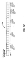
- DLU database device 324 of this example has a data structure 330 illustrated in Fig. 12, with the following fields:
- DLU disk array 322 (see Fig. 11) includes one or more DLU virtual cartridges 326.
- Each virtual cartridge contains:
- DLU cartridge device 326 (see Fig. 11) of this example has a data structure 350 illustrated in Fig. 13, with the following fields:
- the current directory position 353 in field 354 and the current data position 355 in field 356 record the current status of the cartridge and provide a sequential access method to the DLU cartridge device 326.
- a 32K SCSI Write command may be implemented as follows:
- a SCSI Space command (“space backwards one block”), may be implemented as follows:
- Fig. 11 also illustrates the assignment of one VTL front-end FC port (312, 314) to one or more VTL devices (VTL tape 319 and/or VTL robot 315). It further illustrates "visible LUNs" 317 associated with each VTL device (e.g., LUN0 and LUN1 associated with port 0, and LUN4 and LUN1 associated with port1).
- Front-end ports 312, 314 and visible LUNs 317 are defined in a VTL configuration file: vtl.cfg. Almost all SCSI commands are addressed to a specific LUN. Commands that are not addressed to a specific LUN are handled by the front-end port itself ("target collector"); an example is a report LUN. SCSI commands can be classified as: data-in commands (e.g., read); data-out commands (e.g., write); and no data commands (e.g., rewind).
- data-in commands e.g., read
- data-out commands e.g., write
- no data commands e.g., rewind
- Fig. 14 illustrates a timing sequence for forwarding and execution of a SCSI data-in command for the read operation.
- the host sends a FCP_CMD command to the target collector (222 in Fig. 10); it is forwarded to the VTL device (226 in Fig. 10), and then to the DLU device (228 in Fig. 10).
- DLU device 228 executes the command, by reading data from the physical DLU disk array (196 in Fig. 10).
- the read data is transmitted back to VTL device 226, and is included in a FCP_DATA response generated by VTL device 226 and forwarded via target collector 222 back to the host.
- VTL device 226 also generates a FCP_RSP response which is sent back to the host.
- Fig. 15 illustrates a timing sequence for a SCSI write command.
- the host issues a FCP_CMD (a SCSI write) command, followed by FCP_DATA (the data transfer), which are sent to target collector 222 of the VTL server.
- the target collector forwards the data to VTL device 226, which in reply sends a FCP_RSP response back to the host.
- VTL device 226 forwards the data to DLU device 228, which in turn forwards the data to physical DLU disk array 196.
- Fig. 15 further illustrates a dual buffer mechanism which enables the VTL software to manage commands on both its front-end (connected to the hosts) and back-end (connected to disk storage) simultaneously. While the back-end is busy writing to the disk, the front-end can process the next write command (see dotted arrow with FCP_CMD command in Fig. 15).
Abstract
Description
- The present invention relates to systems and methods for emulating tape storage.
- Data backup is an essential element of the data protection process in every organization. Historically it has involved sending a backup copy of the data to a tape storage device. Exponential data growth, a shrinking backup window, heterogeneous platforms and applications (an open systems environment), and rising downtime costs are some of the data storage challenges facing IT administrators today. As a result, data backup is now typically the number one storage problem for IT administrators.
- A traditional
backup system architecture 10, shown in Fig. 1, has a backup application residing on abackup server 14 and acting as the point of management and control for both the backup process and associated tape hardware.Backup server 14 is typically disposed on a local area network (LAN) 16, where it is connected to a plurality of local hosts (e.g., PC's and other servers (not shown) requiring data backup) and to atape library 18. However, a variety of different backup applications are now available from various vendors, each compatible with different operating systems, storage systems and applications. Integrating these various backup applications into an open systems environment, with heterogeneous hosts and heterogeneous tape storage systems, is a significant challenge. - Apart from the difficulties of integrating the different systems, backup and recovery from tape is itself an inherently labor-intensive, complex and error prone process. The success rate for tape backup varies between 95 and 99%; for tape recovery, a less frequent but very critical operation, it is even lower. The operational costs related to tape backup and recovery management keep rising as the complexity of the system and the amount of data increase.
- As a result of these problems, new data protection schemes have been proposed. One approach is to integrate disk-based cache (an expensive form of temporary storage typically used for application data) to improve backup performance and reduce recovery time. Another approach is to utilize disk-based library storage for data backup, this too being a more expensive alternative than tape storage. Some systems emulate a tape storage device with a disk storage device. In one such emulation system, commonly used in a mainframe (dedicated host and storage device) environment, tape requests are intercepted in the host server and converted to disk requests so that an unmodified magnetic disk storage device can emulate (act as a virtual) magnetic tape storage device.
- While solving some of the problems of traditional tape-based backup and recovery methods, these new approaches have generated problems of their own. Many of these new approaches do not integrate seamlessly into the variety of existing backup applications and procedures of open systems environments. Some approaches require new systems hardware, as well as software. Others are too expensive, requiring additional disk space in primary (expensive, high performance) storage disk arrays. Furthermore, many of these approaches do not consolidate the backup data procedures, but rather are niche solutions suited to only a portion of the data handled by a data center.
- , Whereas tape storage has been central to data backup, disk storage has been central to applications storage (i.e., primary storage), which requires more immediate access to data. Thus, traditional disk arrays have been optimized for application storage performance. These storage arrays include RAID architectures for data availability, redundant support systems for reliability of the full data array, wide band channels to support high throughput, and caching to reduce input/output (I/O) latency. Because of their criticality to systems operation, applications storage arrays are also designed with redundant components (including the disks themselves) that can be removed and replaced without interrupting systems operation (referred to as "hot swap" capability). As a result of their increased complexity, application storage arrays typically cost at least ten times the amount of raw disk space.
- For most data protection applications, and specifically for backup, many of these design complexities are not required. Additionally, while application storage systems must be designed so that the full data array is available at all times, most data protection applications require only a small fraction (e.g., ten percent or less) of the data to be active at any time.
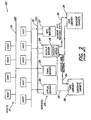
- Fig. 2 illustrates an enhanced
backup architecture 20 which includes both disk and tape storage. In this schematic drawing, a plurality of hosts 21 (e.g., computers) are connected by aLAN 22. A plurality ofservers 24, e.g.,application server 25,e-mail server 26,web server 27, andbackup server 28 on whichbackup application 29 resides, are connected by a Storage Area Network (SAN) 30, and toLAN 22.Data paths backup server 28 and each ofdisk library 38, which serves as a target for backup data, andtape library 36, which serves as a target for archive data. Systems of this type have been implemented ad hoc to reduce backup times and/or to increase the confidence and completion (success rate) of backup within a given backup window. However, the ability to scale such an architecture is limited, particularly in open systems environments which include a variety of different vendors' equipment. - Thus, there is a need to provide a backup data protection system having a more cost-effective combination of some (and preferably all) of the following characteristics: capacity; performance; availability; cost; compatibility; simplicity; and scalability.
- Reference is made to
WO 02/27462 -
WO 02/27462 US 5438674 which discloses an optical disk storage system. - According to one aspect of the invention there is provided a method in accordance with
claim 1. - Another aspect of the invention provides a virtual tape server in accordance with claim 6.
- A third aspect of the invention provides computer program product according to claim 13.
- In the various implementations described in this application, the order of method steps or arrangement of apparatus elements provided is not limiting unless specifically designated as such.
-
- Fig. 1 is a schematic diagram of a prior art backup system architecture including a backup application residing on a backup server;
- Fig. 2 is a schematic diagram of a more elaborate prior art backup architecture which includes both disk and tape storage devices;
- Fig. 3 is a schematic diagram of an implementation consistent with the invention which provides a virtual storage pool;
- Fig. 4 is a schematic diagram of a network architecture for an implementation consistent with the invention, including a Virtual Tape Library (VTL) server and Disk Library Unit (DLU);
- Fig. 5 is a schematic illustration of a network architecture for another implementation, having multiple Disk Library Units (DLUs);
- Fig. 6 is a schematic diagram of a network architecture for another implementation, having both multiple VTL servers and multiple DLUs;
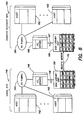
- Fig. 7 is a schematic diagram of a network architecture for another implementation, including a local backup data site and an offsite archiving site;
- Fig. 8 is a schematic diagram of a network architecture for another implementation, including a local site for storing backup data and a disaster recovery site for remote mirroring;
- Fig. 9 is a schematic illustration of the hardware components of a VTL server according to an implementation consistent with the invention;
- Fig. 10 is a corresponding software block diagram for the VTL server of Fig. 9;
- Fig. 11 is a schematic illustration of a DLU system architecture for an implementation consistent with the invention;
- Fig. 12 is an example of a DLU database device data structure according to one implementation consistent with the invention;
- Fig. 13 is an example of a DLU cartridge device database structure according to one implementation consistent with the invention;
- Fig. 14 illustrates a command sequence for a SCSI read command; and
- Fig. 15 illustrates a command sequence for a SCSI write command.
- Various implementations consistent with the invention will now be described. These methods and systems, which illustrate the invention, provide different combinations of benefits, for example in regard to capacity, performance, availability, cost, compatibility, simplicity and scalability.
- According to one implementation, Fig. 3 shows an open systems environment including a
LAN network 40 connecting a plurality of mixed Unix and NT computer hosts 41, 42, 43, 44. These hosts are also connected to a Storage Area Network (SAN) 46, which comprises a shared network of storage devices. The SAN is connected to what is shown schematically as a "virtual storage pool" 48. This virtual storage pool includes disk-based storage devices and a system for utilizing the disk storage to emulate tape storage. The pool can be integrated seamlessly into an open systems backup and recovery environment. By "integrated seamlessly" it is meant that no significant changes (special software or configuration) are required to the host backup applications, drivers or other components of the IT infrastructure, including the disk-based storage devices. - The virtual storage pool can be implemented (in one example) with at least one Virtual Tape Library (VTL) server, described below, which receives backup tape commands from heterogeneous hosts and is connectable to one or more disk storage devices for transparently creating virtual pools of tape storage in disparate systems. It allows users to emulate various vendors' tape devices in the same storage pool. As used herein, tape device means a tape storage device such as a tape library, tape drive, or other tape-based storage apparatus. Specific examples include a Quantum™ DLT7000 tape drive, and an ATL P3000 automated tape library.
- The VTL server allows multiple heterogeneous hosts, running different operating systems and different backup applications, to simultaneously connect to various vendors' disk devices. Disk device means a disk storage device such as a disk drive or disk array. Such disk devices are available from EMC™, HP™, IBM™, etc., including ATA-based disk arrays (a new low-cost disk technology). A specific example of a disk array is the EMC Symmetrix™ 5.5.
- When a backup application host sends a backup command, addressed to a specific tape storage device, the VTL server replies to the host as though it (the VTL server) were the addressed tape storage device, and then emulates the requested tape operation with one or more of the disk devices. Based on communications with the VTL server, the host believes that the backup transaction has taken place on the addressed tape storage device.
- In this open systems environment, multiple hosts may be running multiple vendors' operating systems (e.g., UNIX, Windows NT). The hosts may also be running multiple vendors' backup applications (e.g., ArcServe™, NetBackup™, Networker™, TSM™). As used herein, a backup application provides tape management for backup and recovery functions.
- A more specific implementation of the virtual storage pool is illustrated in Fig. 4. Fig. 4 shows a plurality of
hosts 50 connected by a Fibre Channel (FC)fabric 52 to aVTL server 54; the VTL server is in turn connected by Fibre Channel (FC) link 56 to an associated Disk Library Unit (DLU) 58. The "front end" 53 of the VTL server, which is connected by theFibre Channel fabric 52 to the plurality ofhosts 50, provides scalable connectivity to a plurality of host backup applications. The "back end" 55 of the VTL server is connected toDLU 58, which includes a plurality of disk-based storage devices orarrays 59. - In another implementation, illustrated in Fig. 5, a plurality of
hosts 70 are again connected by aFC fabric 72 to aVTL server 74, but here the VTL server is connected on the back end by a plurality ofFibre Channels DLUs 80, 82 (here two). In this example, theback end 75 ofVTL Server 74 provides scalable connectivity and can utilize several DLU disk arrays in parallel. - In yet a further implementation, shown in Fig. 6, a plurality of
hosts 90 are connected byFC fabric 92 to a plurality ofVTL servers FC fabric 106 to a plurality ofdisk library units 108, 110 (here two). In this example, scalable connectivity is provided at both the front ends 93, 97, 101 of each respective VTL server to the plurality ofhosts 90, and at the back ends 95, 99, 103 of each respective VTL server to the plurality ofDLUs - These implementations illustrate what may be referred to as "virtual tape data storage", among a variety of different hosts and a variety of different disk storage devices. This eliminates the need for dedicated drives, e.g. where a specific disk drive is allocated to a specific backup application host. In this example, data from one or more hosts can be simultaneously streamed to one or more VTL servers, and on to one or more disk devices emulating one or more tape devices.
- In these examples, the VTL server provides a "virtual image" of a compatible tape storage device on its front end to the host(s). The VTL server also appears to be a compatible host on its back end to the disk storage device(s).
- In these examples, data can be streamed directly from one or more hosts to the one or more physical storage disk drives or disk libraries. By "directly", it is meant that there is no intermediate hard disk array staging area, which additional storage system and step would tend to increase the cost and/or complexity of the system. Furthermore, there is no intermediate or second point of management and control added for backup operations. Rather, the backup application from the host continues to serve as a single point of management and control for backup operations. As used herein, backup operations includes both backup and recovery operations.
- Furthermore, the implementations described above do not require additional disk space in primary (expensive, high performance) storage disk arrays.
- Another benefit is that the VTL server can run on a standard off-the-shelf server, such as an Intel™-based Linux or UNIX server, e.g. Dell™ 4600, and Sun™ Solaris 5.8 servers.
- The implementations described above are distinguishable from the prior art which utilizes hard disk array staging areas to improve backup performance and reduce time to data recovery. These prior art systems offload the actual backup transaction from the tape libraries onto the staging area, placing the backup data in, for example, RAID cache, to be transferred over to a tape library at a later specified time. Thus, instead of writing the data directly from the host to the storage device, they write the data to a high-speed RAID cache disk, wherein the data can later be written to another storage device at a time completely independent of the data being backed up, i.e., not within the backup window.
- Also distinguishable are virtual tape servers used in the mainframe environment, sold for example by IBM™ and StorageTek™, which do not replace the tape library storage but enhance their functionality by providing intermediate disk cache acting as buffer to the tape drives and providing additional management capability for the tape library storage systems.
- Instead, in one implementation consistent with the invention, the tape libraries are replaced by a Virtual Tape Library (VTL) unit which has a configurable number of virtual tape drives and virtual tape cartridges. The system can emulate both a Tape Library Unit (TLU) robotics and a configurable number of tape drive devices. It is configurable to meet a customer's needs, for example in regard to the number of virtual tape cartridges, virtual cartridge size, and protection level (RAID).
- Furthermore, the VTL system includes a VTL server which emulates the tape drives and tape library units transparently. The VTL virtual tape drives can self identify, through a SCSI command (described in further detail below), as a SCSI tape drive device (e.g., whose vendor ID is Quantum and product ID is DLT7000). Similarly, the VTL virtual tape library unit can self identify through a SCSI command as a SCSI tape library unit (e.g., whose vendor ID is Quantum and product ID is ATL P3000). Thus, the VTL server appears to the host as the designated physical tape storage device.
- Other implementations are illustrated in Figs. 7 and 8. In both of these implementations, a local site includes a
VTL server hosts FC fabric VTL servers 124, 146 (respectively), and theVTL servers FC DLUs 128, 150 (respectively). Where they differ is that in Fig. 7, a physical tape library unit (TLU) 130 is also connected viaFC fabric 122 and functions as a data import/export device to allow off-site archiving of data (see arrow 134). Abackup application 121 inhost 120 initiates and controls media duplication (seearrows 135; 136) of data stored in the DLU 128 (the virtual storage pool) which is then sent to theTLU 130 for archiving. Theindividual tape cartridges 131 in the TLU can then be physically removed (by robotics arm 133) and transported to an off-site location for off-site archiving (arrow 134). Duplication is a common feature in open systems backup applications, such as Veritas™ NetBackup, Legato™ NetWorker, etc. - In Fig. 8, a
local site 140 includesVTL server 146 andDLU 150 as the primary (virtual) library for active backup data. At a remotedisaster recovery site 160, there is provided anotherVTL server 166 connected byFC fabric 164 to a plurality ofhosts 162, and by FC link 167 toDLU 168. Remote mirroring between the local and remote DLUs 168 and 150 (see arrow 170) is used to recover data from thedisaster recovery site 160 that has been lost at thelocal site 140. - Figs. 9-10 illustrate a specific implementation of a VTL server acting as a disk-based
tape emulation system 180 in an open systems environment, consistent with the invention. Fig. 9 is a schematic illustration of the hardware components, while Fig. 10 is a schematic illustration of the software components. - As shown in Fig. 9, an NT (or Unix)
host 182 is connected viaFibre Channel 184 to afront end 186 of aVTL server 188. Aback end 192 ofVTL server 188 is connected by aFibre Channel 194 to aDisk Library Unit 196.Host 182 includes abackup application 183 which acts as an "initiator" in issuing a command to a "target" tape storage device. This implementation utilizes the Fibre Channel Protocol (FCP) for SCSI, second version (hereinafter FCP-2), a draft proposed by the American National Standards Technical Committee T10, Project 1144D, Revision 8, September 23, 2002 (available at www.t10.org). This standard describes a frame format and protocol for transferring commands and data between a SCSI (Small Computer System Interface) initiator and target using the FC (Fibre Channel) transmission standards. Before discussing further the implementation of Figs. 9-10, a short summary of the SCSI and FC standards is provided. - The Small Computer System Interface (SCSI) command set is widely used today for a variety of device types. The transmission of SCSI commands across Fibre Channel links allows the large body of SCSI application and driver software to be used in the Fibre Channel (FC) environment.
- FCP-2 is part of the SCSI family of standards developed by T10 to facilitate the use of SCSI command sets, for many different types of devices across many different types of physical interconnects. The architectural model for the family of standards is set forth in NCITS Project 11570, Information Technology -SCSI Architecture Model-2 (SAM 2).
- Fibre Channel (FC) is implemented as a high-speed serial architecture that allows either optical or electrical connections at data rates from 265 Mbits up to 4 Gbits per second. Topologies supported by Fibre Channeling include point-to-point, fabric switched, and arbitrated loop. All FC connections use the same standard frame format and standard hierarchy of transmission units to transmit Information Units (lUs) that carry SCSI information.
- Fibre Channel (FC) is logically a point-to-point serial data channel. The architecture may be implemented with high-performance hardware that requires little real-time software management. The FC protocol utilizes the multiplexing and shared bandwidth capabilities provided by various FC classes of service and provides options for reliable error detection and error recovery independent of the class of service.
- FCP-2 defines a Fibre Channel mapping layer (FC-4) that uses the services defined by NCITS Project 1311D, "Fibre Channel Framing And Signaling Interface (FC-FS)", to transmit SCSI command, data, and status information between a SCSI initiator and a SCSI target. The following definitions from FCP-2 are relevant:
- 3.1.6 application client: An object that is the source of SCSI commands.
- 3.1.9 command: A request describing a unit of work to be performed by a device server.
- 3.1.12 data in delivery service: A confirmed service used by the device server to request the transfer of data to the application client.
- 3.1.13 data out delivery service: A confirmed service used by the device server to request the transfer of data from the application client.
- 3.1.16 device server: An object within the logical unit that executes SCSI tasks and enforces the rules for task management.
- 3.1.20 FCP Exchange: A SCSI I/O Operation for the Fibre Channel FC-2 layer. The SCSI I/O Operation for Fibre Channel is contained in a Fibre Channel Exchange.
- 3.1.21 FCP I/O operation: A SCSI I/O Operation for the Fibre Channel FC-4 layer, as defined in FCP-2.
- 3.1.22 FCP_Port: An N_Port or NL_Port that supports the SCSI Fibre Channel Protocol.
- 3.1.27 Information Unit: An organized collection of data specified by the Fibre Channel protocol to be transferred as a single Sequence by the Fibre Channel service interface.
- 3.1.28 initiator: A SCSI device containing application clients that originate device service requests and task management functions to be processed by a target SCSI device. In this standard, the word "initiator" also refers to an FCP_Port using the Fibre Channel protocol to perform the SCSI initiator functions defined by SAM-2.
- 3.1.31 logical unit: A target resident entity that implements a device model and processes SCSI commands sent by an application client.
- 3.1.32 logical unit number: An encoded 64-bit identifier for a logical unit.
- 3.1.54 SCSI device: A device that originates or services SCSI commands.
- 3.1.55 SCSI I/O operation: An operation defined by a SCSI command, a series of linked SCSI commands or a task management function.
- 3.1.58 target: A SCSI device that receives SCSI commands and directs such commands to one or more logical units for execution. In this standard, the word "target" also refers to an FCP_Port using the Fibre Channel protocol to perform the SCSI target functions defined by SAM-2.
- 3.1.60 task: An object within the logical unit representing the work associated with a command or group of linked commands.
- The Fibre Channel physical layer (FC-2 layer) described by FC-FS performs those functions required to transfer data from one port to another (referred to as FCP_Ports). A switching fabric allows communication among more than two FCP_Ports. An arbitrated loop (FC-AL) is an alternative multiple port topology that allows communication between two ports on the loop, or between a port on the loop and a port on a switching fabric attached to the loop.
- The FCP device and task management protocols define the mapping of SCSI functions, defined in SCSI Architecture Model-2 (SAM-2), to the Fibre Channel interface defined by FC-FS. The I/O operation defined by SAM-2 is mapped into a Fibre Channel exchange. A Fibre Channel exchange carrying information for a SCSI I/O operation is an FCP exchange. The request and response primitives of an I/O operation are mapped into Information Units (lUs) as shown in Table 1.
Table 1 - SCSI and Fibre Channel protocol functions SCSI function FCP equivalent I/O operation Exchange Protocol Service Request and Response Sequence Send SCSI Command Request Unsolicited command IU (FCP_CMND) Data delivery request Data descriptor IU (FCP_XFER_RDY) Data delivery action Solicited data IU (FCP_DATA) Send Command Complete Response Command status IU (FCP_RSP) REQ/ACK for Command Complete Confirmation IU (FCP_CONF) - An application client begins an FCP I/O operation by invoking an Execute Command remote procedure call (see SAM-2). The Execute Command call conveys a single request or a list of linked requests from the application client to the FCP service delivery subsystem. Each request contains all the information necessary for the execution of one SCSI command, including the local storage address and characteristics of data to be transferred by the command. The FCP then performs the following actions using FC-FS services to perform the SCSI command.
- The FCP_Port that is the initiator for the command starts an Exchange by sending an unsolicited command IU containing the FCP_CMND IU payload, including some command controls, addressing information, and the SCSI command descriptor block (CDB).
- When the device server for the command has completed the interpretation of the command, has determined that a write data transfer is required, and is prepared to request the data delivery service, it sends a data descriptor IU containing the FCP_XFER_RDY IU payload to the initiator to indicate which portion of the data is to be transferred. The FCP_Port that is the initiator then transmits a solicited data IU to the target containing the FCP_DATA IU payload requested by the FCP_XFER_RDY IU. The data delivery request and returning payloads continue until the data transfer requested by the SCSI command is complete.
- Alternatively, when the device server for the command has completed the interpretation of the command and has determined that a read data transfer is required, the FCP_Port that is the target transmits a solicited data IU to the initiator containing the FCP_DATA IU payload. Data deliveries containing payloads continue until all data described by the SCSI command is transferred.
- After all the data has been transferred, the device server transmits the Send Command Complete protocol service response (see SAM-2) by requesting the transmission of an IU containing the FCP_RSP IU payload. That payload contains the SCSI status and, if the SCSI status is CHECK CONDITION, the autosense data describing the condition. The FCP_RSP IU indicates completion of the SCSI command. If no command linking, error recovery or confirmed completion is requested, the FCP_RSP IU is the final sequence of the Exchange. Other details of the protocol are available at www.t10.org.
- Referring back again to Fig. 9, at the
front end 186 ofVTL server 188 there is adevice driver 200 which acts as a SCSI target and accepts the host (initiator) request (command). Thus,driver 200 receives Fibre Channel frames containing an SCSI over FC (FCP) command (the FCP_CMND Information set).Driver 200 stores the frames inmemory 201 inVTL server 188. Thendriver 200 forwards the frames (containing the FCP command) to atarget emulator 204. - The
target emulator 204 receives the host request (command) and identifies itself as either a tape drive (SCSI stream device) or a tape library unit robotics (SCSI medium changer). The target emulator software understands the content of and processes FCP commands. For this purpose, it needs to understand four fields in the FCP command, namely: - ■ Opcode
- ■ Logical Unit Number (LUN)
- ■ Read/Write (here in the target emulator read and write mean "data in delivery service" or "data out delivery service")
- ■ Command/Task Management
- In this context a SCSI command is addressed to a specific LUN (e.g., a specific tape device - tape drive or TLU robotics). The target (e.g., a TLU) may be the front end for a plurality of LUNs. In contrast, a SCSI task management command is intended for the entire target. The
target emulator 204 checks to see if the tape device identified by the LUN in the command, exists. Thetarget emulator 204 also checks the command's write field, and if flagged, checks whether a buffer is available to hold data. If it is, theemulator 204 sends a transfer ready signal back to the host. It adds FCP details to the response, without specifying what type of storage is attached. - More specifically,
emulator 204, being aware of the format of the FCP_CMND information set, can access thememory 201 in which the command is stored and proceed to analyze it: - ■ It checks the "SCSI CDB opcode" and verifies that it is a valid opcode.
- ■ It checks the LUN (which identifies a specific virtual tape drive device or a virtual tape library robotics) and verifies that it exists.
- ■ If the opcode is illegal, or there is no virtual device (tape drive or robotics) associated with the LUN,
emulator 204 rejects the command by sending back (through driver 200) a response to thehost 182 with an appropriate error code (this response is called FCP_RSP). - ■ If the opcode is legal, and there is a virtual device associated with the command:
- ■ If the command is a "data-out" command, meaning the hosts are sending (writing) data to the VTL server,
emulator 204 starts the data transfer (i.e., notifieshost 182 thatVTL server 188 is ready and the host can start sending the data to the VTL server). The data is transferred to a specific buffer inmemory 201 of the VTL server (there are two buffers assigned to each VTL virtual tape drive for this purpose). - ■ If it is not a "data-out" command, or if it is a "data-out" command and all of the data has already been transferred to the VTL, emulator 204 (through a queue) forwards the FCP_CMD (and the buffer containing the data, if it was a "data-out" command) to tape/
disk command converter 206.
- ■ If the command is a "data-out" command, meaning the hosts are sending (writing) data to the VTL server,
- Thus, the command is next sent to
converter 206 which converts the tape command to a disk command and creates a disk storage model. The converter software knows how to store the data to disk, how to catalog what data is written where, and how to manage the disk. -
Converter 206 will check the SCSI CDB opcode and execute the specific action/operation required by the opcode.Converter 206 executes the action/operation either on its own, or by calling a function of theDLU 196. TheDLU 196 is responsible for storing data to the disks and managing the status of the virtual tape library. Each emulated tape drive and tape robotics will correspond with a different LUN. Thus, the LUN in the address field of the FCP_CMD can be either for a stream device (tape drive) or a medium changer (tape robotics).Converter 206 knows how to send commands to the disk in either tape device or robotics formats. - Once the required action/operation is complete,
converter 206 sends a response viaemulator 204 to thehost 182 indicating the completion status (FCP_RSP). - Fig. 10 is the corresponding schematic software block diagram for
VTL server 188 of Fig. 9. A first block, connected to inputFC link 184, is anFC driver block 220 which corresponds todevice driver 200 in Fig. 9. A second block is a FC-SCSI port block 222, which provides the functionality oftarget emulator 204. A third block provides an emulated SCSItape storage device 224.Block 224 may include several instances (oneinstance 226 per virtual tape drive or virtual robot) of VTL tape and robot objects, each having a different LUN, and comprises the tape storage model; it further includes aset 228 of associated DLU tape and robot objects, comprising the disk storage model. EachVTL tape object 227 has a correspondingDLU tape object 229 in thedisk storage model 228. Similarly, eachVTL robot object 230 has a correspondingDLU robot object 231 in the disk storage model. The objects in thedisk storage model 228 correspond to data which is then stored in thedisk library unit 196.DLU 196 holds both the data received fromhost 182, and the data describing the emulated tape device (see e.g., Fig. 11). The latter may comprise a database, such as relational table, stored in the DLU. A more detailed description of one particular DLU system architecture follows. - A more specific implementation of a DLU system architecture for emulating a tape library unit (TLU) is shown in Fig. 11. This figure also illustrates the correlation of
LUN identifiers 317 with VTL devices (tape drives 319 and TLU robotics 315). - A
VTL 310 server (shown schematically) has two front-end ports, front-end port 0 (312) and front-end port 1 (314).VTL server 310 has two back-end ports FC fabric 320 toDLU disk array 322.Disk array 322 includes aDLU database device 324 and multipleDLU cartridge devices 326. -
VTL server 310 has residing thereonVTL software 311 with aDLU model 313 of the emulated tape devices - virtual tape drives 319 andvirtual TLU robotics 315.DLU model 313 manages the DLU disk array persistent storage, which includes: - DLU cartridges; and
- DLU robotics, bins, import/export slots, and tape drives.
DLU 322 emulates the TLU robotics and a configurable number of tape drive devices; the DLU virtual tape drives provide "sequential access" to random access devices (DLU cartridge devices 326). -
DLU database device 324 contains configuration information for all elements in the virtual tape library emulated by the DLU. It further contains the status of all such elements in the virtual tape library, namely: - robot;
- bins (slots that hold the virtual cartridges);
- tape drives;
- import/export slots; and
- shared boxes, which allow two or more VTL servers to be attached to the same DLU disk array.
- The information in
DLU database device 324 is updated each time there is a command that changes the status of one or more elements in the virtual tape library. For example, an SCSI Move command sent to the DLU robot (315 in DLU model 313) asks the robot to move a cartridge from a bin to a tape drive (319 in DLU model 313); this changes the status of the respective bin and the status of the respective tape drive, which status changes will be made in theDLU database device 324. -
DLU database device 324 of this example has adata structure 330 illustrated in Fig. 12, with the following fields: -
configuration information 332, which includes: number of robots; number of bins; number of tape drives; number of import/export slots; number of shared boxes; virtual cartridges information; -
robot mailbox 334, which contains the information and status of the robot; there is one entry for each configured robot (normally, there is only one configured robot); -
bin mailbox 336, which contains the information and status of the bin; for example, the bin may be full or empty; if full, the label of the virtual cartridge that occupies the bin is provided; there are as many entries as there are configured bins; -
tape mailbox 338, contains the information and status of the tape drive; for example, the tape drive may be full or empty; if full, the label of the virtual cartridge that occupies the tape drive is provided; there are as many entries as configured tape drives; - import/
export mailbox 340, which contains the information and status of the import/export slot; there are as many entries as configured slots; -
share mailbox 342, which contains the information of the VTL server connected to the DLU disk array; there is one entry for each VTL server attached to the DLU disk array. - DLU disk array 322 (see Fig. 11) includes one or more DLU
virtual cartridges 326. Each virtual cartridge contains: - some configuration information, such as the virtual
- cartridge label, the virtual cartridge barcode, etc.;
- the data written by the user;
- the cartridge directory that describes the data that has been written to the cartridge and the current position of the cartridge.
- DLU cartridge device 326 (see Fig. 11) of this example has a
data structure 350 illustrated in Fig. 13, with the following fields: - DLU
virtual cartridge 352, which contains configuration information such as the label, barcode, etc.; - DLU
virtual cartridge directory 354; - DLU virtual
cartridge user data 356; -
early warning indication 358; - end of
media indication 360. - The
current directory position 353 infield 354 and thecurrent data position 355 infield 356 record the current status of the cartridge and provide a sequential access method to theDLU cartridge device 326. - For example, a 32K SCSI Write command may be implemented as follows:
- the DLU will add an entry to the
cartridge directory 354 in the position pointed to by the "current directory position" 353. This entry will state the size of the IO (e.g., 32K); - the "current directory position" 353 will be moved forward by one entry;
- the DLU will write the 32K data sent in the Write command to the position pointed to by the "current data position" 355;
- the "current data position" 355 will be moved forward by 32K;
- if the "early warning indication" 358 or the "end of media indication" 360 are reached while writing the data, the respective indication is sent back in the response to the write command (in the FCP_RSP).
- As another example, a SCSI Space command ("space backwards one block"), may be implemented as follows:
- the "current directory position" 353 is moved back one entry;
- the content of the entry pointed to by the "current directory position" 353 is read (e.g., 32K);
- the "current data position" 353 is moved back according to the value read in the directory entry (32K).
- Fig. 11 also illustrates the assignment of one VTL front-end FC port (312, 314) to one or more VTL devices (
VTL tape 319 and/or VTL robot 315). It further illustrates "visible LUNs" 317 associated with each VTL device (e.g., LUN0 and LUN1 associated with port 0, and LUN4 and LUN1 associated with port1). - Front-
end ports visible LUNs 317 are defined in a VTL configuration file: vtl.cfg. Almost all SCSI commands are addressed to a specific LUN. Commands that are not addressed to a specific LUN are handled by the front-end port itself ("target collector"); an example is a report LUN. SCSI commands can be classified as: data-in commands (e.g., read); data-out commands (e.g., write); and no data commands (e.g., rewind). - Fig. 14 illustrates a timing sequence for forwarding and execution of a SCSI data-in command for the read operation. The host sends a FCP_CMD command to the target collector (222 in Fig. 10); it is forwarded to the VTL device (226 in Fig. 10), and then to the DLU device (228 in Fig. 10).
DLU device 228 executes the command, by reading data from the physical DLU disk array (196 in Fig. 10). The read data is transmitted back toVTL device 226, and is included in a FCP_DATA response generated byVTL device 226 and forwarded viatarget collector 222 back to the host.VTL device 226 also generates a FCP_RSP response which is sent back to the host. - Fig. 15 illustrates a timing sequence for a SCSI write command. The host issues a FCP_CMD (a SCSI write) command, followed by FCP_DATA (the data transfer), which are sent to target
collector 222 of the VTL server. The target collector forwards the data toVTL device 226, which in reply sends a FCP_RSP response back to the host.VTL device 226 forwards the data toDLU device 228, which in turn forwards the data to physicalDLU disk array 196. - Fig. 15 further illustrates a dual buffer mechanism which enables the VTL software to manage commands on both its front-end (connected to the hosts) and back-end (connected to disk storage) simultaneously. While the back-end is busy writing to the disk, the front-end can process the next write command (see dotted arrow with FCP_CMD command in Fig. 15).
Claims (13)
- A method for storing backup data in a system wherein a virtual tape (VT) server (54) resides on a network and is connected to one or more disk storage devices (59) and to a plurality of heterogeneous backup hosts (50) in a n open systems environment, wherein the VT server receives initiator commands from the backup hosts for target tape storage devices said initiator commands consisting of commands addressing a tape drive device and commands addressing a robotics device the method comprising the VT server:accepting one of the initiator commands and responding as if the VT server were the target tape storage device; andemulating the target tape storage device by converting the received initiator command to a disk storage command for implementing the received initiator command with the one or more disk storage devices (59),wherein the initiator commands are SCSI commands addressed to tape storage devices with logical unit numbers (LUNS) and wherein the VT server includes a model (313) having tape objects (227) and robot objects (230) describing a tape library including robotics and tape drive devices, wherein the VT server emulates the tape drive devices and robotics of said emulated target tape storage device.
- The method of claim 1, wherein at least one of the hosts (120) has a backup application (121) which issues the initiator commands and serves as a single point of management and control for backup operations.
- The method of claim 1, wherein emulation data is stored describing the emulated target tape storage devices.
- The method of claim 3, wherein the emulation data has a data structure including one or more of the following fields: configuration information, robot mailbox, bin mailbox, tape mailbox, import/export mailbox, and share mailbox.
- The method of claim 3 or 4, wherein the emulation data has a data structure including one or more of the following fields: configuration information, cartridge directory, and cartridge data.
- A virtual tape server comprising:a front end (53) connectable to one or more heterogeneous hosts (50) in an open systems environment and configured to accept initiator commands intended for target tape storage devices from the one or more hosts, said initiator commands consisting of commands addressing a tape drive device, and commands addressing a robotics device;a target emulator (204), coupled to the front end, to receive the initiator command and emulate, as a virtual tape storage device, the target tape storage device addressed by the initiator command;a command converter (206), coupled to the target emulator, to receive the initiator command and convert the initiator command into a disk storage device command;a back end (55), coupled to the command converter and to one or more disk storage devices (59)wherein the initiator commands are SCSI commands addressed to tape storage devices with logical unit numbers (LUNs), the virtual tape server including a model having tape objects (227) and robot objects (230) describing a tape library including robotics and tape drive devices of the target tape storage device, wherein emulation of the target tape storage device comprises emulating the tape drive devices and robotics.
- The server of claim 6, wherein the SCSI commands are adapted for Fibre Channel (FC) transmission.
- The server of claim 6, wherein the one or more disk storage devices comprise one or more of a disk drive and a disk array.
- The server of claim 6, wherein the target emulator (204) identifies itself as either a SCSI stream device or a SCSI medium changer.
- The server of claim 6, wherein emulation data is stored describing the emulated target tape storage devices.
- The server of claim 10, wherein the emulation data has a data structure including one or more of the following fields: configuration information, robot mailbox, bin mailbox, tape mailbox, import/export mailbox, and share mailbox.
- The server of claim 10 or 11, wherein the emulation data has a data structure including one or more of the following fields:configuration information, cartridge directory and cartridge data.
- A computer program product comprising program code means which, when loaded into a computer, cause the computer to implement a method of handing backup data according to any one of claims 1 to 5.
Priority Applications (1)
| Application Number | Priority Date | Filing Date | Title |
|---|---|---|---|
| EP07075121.9A EP1832970B1 (en) | 2003-02-05 | 2004-02-04 | Tape storage emulation for open systems environments |
Applications Claiming Priority (3)
| Application Number | Priority Date | Filing Date | Title |
|---|---|---|---|
| US10/358,350 US20040153614A1 (en) | 2003-02-05 | 2003-02-05 | Tape storage emulation for open systems environments |
| US358350 | 2003-02-05 | ||
| PCT/US2004/003303 WO2004072961A2 (en) | 2003-02-05 | 2004-02-04 | Tape storage emulation for open systems environments |
Related Child Applications (1)
| Application Number | Title | Priority Date | Filing Date |
|---|---|---|---|
| EP07075121.9A Division EP1832970B1 (en) | 2003-02-05 | 2004-02-04 | Tape storage emulation for open systems environments |
Publications (2)
| Publication Number | Publication Date |
|---|---|
| EP1593033A2 EP1593033A2 (en) | 2005-11-09 |
| EP1593033B1 true EP1593033B1 (en) | 2007-10-10 |
Family
ID=32771173
Family Applications (2)
| Application Number | Title | Priority Date | Filing Date |
|---|---|---|---|
| EP07075121.9A Expired - Lifetime EP1832970B1 (en) | 2003-02-05 | 2004-02-04 | Tape storage emulation for open systems environments |
| EP04708242A Expired - Lifetime EP1593033B1 (en) | 2003-02-05 | 2004-02-04 | Tape storage emulation for open systems environments |
Family Applications Before (1)
| Application Number | Title | Priority Date | Filing Date |
|---|---|---|---|
| EP07075121.9A Expired - Lifetime EP1832970B1 (en) | 2003-02-05 | 2004-02-04 | Tape storage emulation for open systems environments |
Country Status (9)
| Country | Link |
|---|---|
| US (3) | US20040153614A1 (en) |
| EP (2) | EP1832970B1 (en) |
| JP (1) | JP4931581B2 (en) |
| CN (1) | CN100547535C (en) |
| AT (1) | ATE375545T1 (en) |
| AU (1) | AU2004211213A1 (en) |
| CA (1) | CA2515448C (en) |
| DE (1) | DE602004009410T2 (en) |
| WO (1) | WO2004072961A2 (en) |
Families Citing this family (118)
| Publication number | Priority date | Publication date | Assignee | Title |
|---|---|---|---|---|
| US7210004B2 (en) * | 2003-06-26 | 2007-04-24 | Copan Systems | Method and system for background processing of data in a storage system |
| US7210005B2 (en) * | 2002-09-03 | 2007-04-24 | Copan Systems, Inc. | Method and apparatus for power-efficient high-capacity scalable storage system |
| US7162604B1 (en) * | 2002-10-08 | 2007-01-09 | Ultera Systems, Inc. | Multi-user virtual tape system |
| US8024172B2 (en) * | 2002-12-09 | 2011-09-20 | Netapp, Inc. | Method and system for emulating tape libraries |
| US7743205B2 (en) * | 2002-12-17 | 2010-06-22 | Quantum Corporation | Apparatus and method for virtualizing data storage media, such as for use in a data storage library providing resource virtualization |
| JP2004227448A (en) * | 2003-01-27 | 2004-08-12 | Hitachi Ltd | Tape management method and system |
| US20040181388A1 (en) * | 2003-03-11 | 2004-09-16 | Yung Yip | System having tape drive emulator and data tape cartridge housing carrying multiple disk drives |
| US20050021524A1 (en) * | 2003-05-14 | 2005-01-27 | Oliver Jack K. | System and method of managing backup media in a computing environment |
| JP4060235B2 (en) * | 2003-05-22 | 2008-03-12 | 株式会社日立製作所 | Disk array device and disk array device control method |
| JP2004348464A (en) * | 2003-05-22 | 2004-12-09 | Hitachi Ltd | Storage device and communication signal shaping circuit |
| US7434097B2 (en) * | 2003-06-05 | 2008-10-07 | Copan System, Inc. | Method and apparatus for efficient fault-tolerant disk drive replacement in raid storage systems |
| US20050210304A1 (en) * | 2003-06-26 | 2005-09-22 | Copan Systems | Method and apparatus for power-efficient high-capacity scalable storage system |
| US7698532B1 (en) * | 2003-06-26 | 2010-04-13 | Symantec Operating Corporation | Method and apparatus for tape library emulation |
| US7127575B2 (en) * | 2003-07-10 | 2006-10-24 | Hitachi, Ltd. | Offsite management using disk based tape library and vault system |
| US7409442B2 (en) * | 2003-08-25 | 2008-08-05 | International Business Machines Corporation | Method for communicating control messages between a first device and a second device |
| US7373559B2 (en) * | 2003-09-11 | 2008-05-13 | Copan Systems, Inc. | Method and system for proactive drive replacement for high availability storage systems |
| US20060090098A1 (en) * | 2003-09-11 | 2006-04-27 | Copan Systems, Inc. | Proactive data reliability in a power-managed storage system |
| US7266668B2 (en) * | 2003-11-24 | 2007-09-04 | Copan Systems Inc. | Method and system for accessing a plurality of storage devices |
| JP4156499B2 (en) * | 2003-11-28 | 2008-09-24 | 株式会社日立製作所 | Disk array device |
| JP4497918B2 (en) | 2003-12-25 | 2010-07-07 | 株式会社日立製作所 | Storage system |
| JP4634049B2 (en) | 2004-02-04 | 2011-02-16 | 株式会社日立製作所 | Error notification control in disk array system |
| US7925680B1 (en) * | 2004-07-21 | 2011-04-12 | Oracle America, Inc. | System and method for processing data management files in a virtual storage environment |
| US7761284B2 (en) | 2004-08-30 | 2010-07-20 | Overland Storage, Inc. | Tape emulating disk based storage system and method with automatically resized emulated tape capacity |
| US20060059423A1 (en) * | 2004-09-13 | 2006-03-16 | Stefan Lehmann | Apparatus, system, and method for creating customized workflow documentation |
| US7523098B2 (en) | 2004-09-15 | 2009-04-21 | International Business Machines Corporation | Systems and methods for efficient data searching, storage and reduction |
| US7434090B2 (en) * | 2004-09-30 | 2008-10-07 | Copan System, Inc. | Method and apparatus for just in time RAID spare drive pool management |
| US7631213B2 (en) * | 2004-12-06 | 2009-12-08 | Johnson R Brent | Data center virtual tape off-site disaster recovery planning and implementation system |
| US8843725B2 (en) * | 2005-09-19 | 2014-09-23 | Spectra Logic Corporation | Virtual interchangeable storage device |
| US7253983B2 (en) * | 2004-12-14 | 2007-08-07 | Spectra Logic Corporation | Variable media tape-based storage system |
| US20080183934A1 (en) * | 2004-12-14 | 2008-07-31 | Spectra Logic Corporation | Optional mobile media storage system |
| WO2006112937A2 (en) * | 2005-02-17 | 2006-10-26 | Overland Storage, Inc. | Tape library emulation with automatic configuration and data retention |
| WO2006090412A2 (en) * | 2005-02-24 | 2006-08-31 | Monish Shah | A data storage system and a method for its operation |
| US7581056B2 (en) * | 2005-05-11 | 2009-08-25 | Cisco Technology, Inc. | Load balancing using distributed front end and back end virtualization engines |
| US20060288057A1 (en) * | 2005-06-15 | 2006-12-21 | Ian Collins | Portable data backup appliance |
| US7647469B2 (en) * | 2005-07-22 | 2010-01-12 | International Business Machines Corporation | Method of assigning virtual import/export element addresses |
| JP2007094578A (en) * | 2005-09-27 | 2007-04-12 | Fujitsu Ltd | Storage system and its component replacement processing method |
| US7523289B2 (en) * | 2005-09-30 | 2009-04-21 | Spectra Logic Corporation | Random access storage system capable of performing storage operations intended for alternative storage devices |
| US7844445B2 (en) | 2005-10-12 | 2010-11-30 | Storage Appliance Corporation | Automatic connection to an online service provider from a backup system |
| US8069271B2 (en) * | 2005-10-12 | 2011-11-29 | Storage Appliance Corporation | Systems and methods for converting a media player into a backup device |
| US7818160B2 (en) * | 2005-10-12 | 2010-10-19 | Storage Appliance Corporation | Data backup devices and methods for backing up data |
| US20070091746A1 (en) * | 2005-10-12 | 2007-04-26 | Storage Appliance Corporation | Optical disc for simplified data backup |
| US20070162271A1 (en) * | 2005-10-12 | 2007-07-12 | Storage Appliance Corporation | Systems and methods for selecting and printing data files from a backup system |
| US8195444B2 (en) | 2005-10-12 | 2012-06-05 | Storage Appliance Corporation | Systems and methods for automated diagnosis and repair of storage devices |
| US7813913B2 (en) | 2005-10-12 | 2010-10-12 | Storage Appliance Corporation | Emulation component for data backup applications |
| US20080028008A1 (en) * | 2006-07-31 | 2008-01-31 | Storage Appliance Corporation | Optical disc initiated data backup |
| US7822595B2 (en) * | 2005-10-12 | 2010-10-26 | Storage Appliance Corporation | Systems and methods for selectively copying embedded data files |
| US7899662B2 (en) * | 2005-10-12 | 2011-03-01 | Storage Appliance Corporation | Data backup system including a data protection component |
| US7702830B2 (en) * | 2005-10-12 | 2010-04-20 | Storage Appliance Corporation | Methods for selectively copying data files to networked storage and devices for initiating the same |
| CN100377065C (en) * | 2006-04-19 | 2008-03-26 | 华中科技大学 | Super large capacity virtual magnetic disk storage system |
| US8681788B2 (en) * | 2006-04-26 | 2014-03-25 | Dell Products L.P. | Accelerating NDMP based virtual tape library operations |
| US8069257B1 (en) * | 2006-05-15 | 2011-11-29 | American Megatrends, Inc. | Universal serial bus system interface for intelligent platform management interface communications |
| US7954099B2 (en) | 2006-05-17 | 2011-05-31 | International Business Machines Corporation | Demultiplexing grouped events into virtual event queues while in two levels of virtualization |
| US7571293B1 (en) * | 2006-06-22 | 2009-08-04 | Emc Corporation | Emulation of point-in-time data copying operations |
| US8065133B1 (en) * | 2006-06-30 | 2011-11-22 | Sanblaze Technology, Inc. | Method for testing a storage network including port level data handling |
| GB2440561B (en) * | 2006-07-28 | 2011-03-30 | Hewlett Packard Development Co | Data storage system |
| JP4844319B2 (en) * | 2006-09-22 | 2011-12-28 | 富士通株式会社 | Virtual tape library device sharing method, virtual tape library device, and program |
| JP4792361B2 (en) * | 2006-09-27 | 2011-10-12 | 富士通株式会社 | Response device, response method, and response program |
| US20080082453A1 (en) * | 2006-10-02 | 2008-04-03 | Storage Appliance Corporation | Methods for bundling credits with electronic devices and systems for implementing the same |
| US20080126446A1 (en) * | 2006-11-27 | 2008-05-29 | Storage Appliance Corporation | Systems and methods for backing up user settings |
| US7620765B1 (en) * | 2006-12-15 | 2009-11-17 | Symantec Operating Corporation | Method to delete partial virtual tape volumes |
| US20080172487A1 (en) * | 2007-01-03 | 2008-07-17 | Storage Appliance Corporation | Systems and methods for providing targeted marketing |
| US20080226082A1 (en) * | 2007-03-12 | 2008-09-18 | Storage Appliance Corporation | Systems and methods for secure data backup |
| US20090031298A1 (en) * | 2007-06-11 | 2009-01-29 | Jeffrey Brunet | System and method for automated installation and/or launch of software |
| US20090030955A1 (en) * | 2007-06-11 | 2009-01-29 | Storage Appliance Corporation | Automated data backup with graceful shutdown for vista-based system |
| JP4983474B2 (en) * | 2007-08-10 | 2012-07-25 | 富士通株式会社 | Virtual library apparatus, virtual library system, and logical volume copying method for virtual library apparatus. |
| US20090063794A1 (en) * | 2007-08-30 | 2009-03-05 | International Business Machines Corporation | Method and system for enhanced data storage management |
| WO2009040954A1 (en) * | 2007-09-28 | 2009-04-02 | Fujitsu Limited | Virtual tape device at original center, virtual tape device at duplicate center, virtual library system and virtual tape control method |
| US7913119B2 (en) * | 2007-10-25 | 2011-03-22 | Her Majesty the Queen in right of Canada, as represented by the minister of public safety | Method and device for verifying integrity of data acquisition pathways |
| US7836030B2 (en) * | 2007-11-13 | 2010-11-16 | International Business Machines Corporation | Data library optimization |
| JP5167888B2 (en) * | 2008-03-19 | 2013-03-21 | 富士通株式会社 | Virtual tape device and control method of virtual tape device |
| US20090300279A1 (en) * | 2008-05-28 | 2009-12-03 | Computer Associates Think, Inc. | Signature Based Method for Sending Packets to Remote Systems |
| WO2010070727A1 (en) * | 2008-12-16 | 2010-06-24 | 富士通株式会社 | Virtual tape device, and program and method for copying virtual tape data |
| CN101815078B (en) * | 2009-02-24 | 2013-10-02 | 无锡众志和达存储技术股份有限公司 | Embedded type virtual tape library parallel memory system |
| EP2414950B1 (en) | 2009-03-31 | 2019-10-09 | Commvault Systems, Inc. | Information management systems and methods for heterogeneous data sources |
| US8250299B2 (en) * | 2009-05-20 | 2012-08-21 | International Business Machines Corporation | Multi-host concurrent writing to magnetic tape |
| US8214611B2 (en) * | 2009-06-04 | 2012-07-03 | Hitachi, Ltd. | Storage subsystem and its data processing method, and computer system |
| WO2011037624A1 (en) * | 2009-09-22 | 2011-03-31 | Emc Corporation | Snapshotting a performance storage system in a system for performance improvement of a capacity optimized storage system |
| US8639769B2 (en) * | 2009-12-18 | 2014-01-28 | International Business Machines Corporation | Handling of data transfer in a LAN-free environment |
| US8413137B2 (en) | 2010-02-04 | 2013-04-02 | Storage Appliance Corporation | Automated network backup peripheral device and method |
| US11256529B2 (en) | 2010-03-17 | 2022-02-22 | Zerto Ltd. | Methods and apparatus for providing hypervisor level data services for server virtualization |
| US10649799B2 (en) * | 2010-03-17 | 2020-05-12 | Zerto Ltd. | Hypervisor virtual server system, and method for providing data services within a hypervisor virtual server system |
| US9158653B2 (en) * | 2010-03-21 | 2015-10-13 | Hewlett-Packard Development Company, L.P. | Determining impact of virtual storage backup jobs |
| US9165015B2 (en) * | 2010-07-29 | 2015-10-20 | International Business Machines Corporation | Scalable and user friendly file virtualization for hierarchical storage |
| US9009724B2 (en) | 2010-09-24 | 2015-04-14 | Hewlett-Packard Development Company, L.P. | Load balancing data access in virtualized storage nodes |
| US8595430B2 (en) * | 2010-09-30 | 2013-11-26 | International Business Machines Corporation | Managing a virtual tape library domain and providing ownership of scratch erased volumes to VTL nodes |
| US8392754B2 (en) * | 2010-10-11 | 2013-03-05 | International Business Machines Corporation | Disaster recovery production takeover |
| US8479041B2 (en) | 2010-10-13 | 2013-07-02 | International Business Machines Corporation | Disaster recovery failback |
| US8671308B2 (en) | 2011-05-02 | 2014-03-11 | International Business Machines Corporation | Optimizing disaster recovery systems during takeover operations |
| US8850139B2 (en) | 2011-05-11 | 2014-09-30 | International Business Machines Corporation | Changing ownership of cartridges |
| US8751858B2 (en) | 2011-05-20 | 2014-06-10 | International Business Machines Corporation | System, method, and computer program product for physical drive failure identification, prevention, and minimization of firmware revisions |
| EP2729876B1 (en) * | 2011-10-14 | 2016-06-01 | Hewlett-Packard Development Company, L.P. | Performing a replication operation in response to movement of a virtual data container |
| GB2496597B (en) * | 2011-11-14 | 2017-10-04 | Bio-Check(Uk) Ltd | Cartridge for containing a sample |
| CN102521072B (en) * | 2011-11-25 | 2013-09-11 | 华为数字技术(成都)有限公司 | Virtual tape library equipment and data recovery method |
| CN102543164B (en) * | 2011-12-29 | 2015-02-11 | 北京控制工程研究所 | Spacecraft DSP chip data protection method |
| CN102609486A (en) * | 2012-01-20 | 2012-07-25 | 无锡众志和达存储技术有限公司 | Data reading/writing acceleration method of Linux file system |
| US8977827B1 (en) | 2012-05-31 | 2015-03-10 | Kip Cr P1 Lp | System, method and computer program product for recovering stub files |
| US9634522B2 (en) | 2012-09-19 | 2017-04-25 | International Business Machines Corporation | Power grid data monitoring and control |
| CN103780634B (en) * | 2012-10-17 | 2017-02-22 | 华为技术有限公司 | Data interaction method and data interaction device |
| CN103049224B (en) * | 2012-12-28 | 2015-12-23 | 华为技术有限公司 | By the methods, devices and systems of data importing physical tape |
| US9009742B1 (en) * | 2013-05-10 | 2015-04-14 | Emc Corporation | VTL adaptive commit |
| US9110599B1 (en) * | 2013-05-10 | 2015-08-18 | Emc Corporation | Thin provisioning of VTL tape pools with MTree logical quotas |
| US9063842B1 (en) * | 2013-05-10 | 2015-06-23 | Emc Corporation | Technique for integrating VTL tape pools with MTree quotas |
| US10263826B1 (en) * | 2013-09-30 | 2019-04-16 | EMC IP Holding Company LLC | Method of initiating execution of mainframe jobs from a virtual tape server |
| US9436591B1 (en) | 2013-09-30 | 2016-09-06 | Emc Corporation | Out-of-band file transfers between a host and virtual tape server |
| CN103605587A (en) * | 2013-11-20 | 2014-02-26 | 上海爱数软件有限公司 | Tape library data backup and filing method |
| US9645766B1 (en) * | 2014-03-28 | 2017-05-09 | EMC IP Holding Company LLC | Tape emulation alternate data path |
| US9240209B1 (en) | 2014-09-30 | 2016-01-19 | International Business Machines Corporation | Pass-through tape access in a disk storage environment |
| US9715418B2 (en) | 2014-12-02 | 2017-07-25 | International Business Machines Corporation | Performance problem detection in arrays of similar hardware |
| US9582207B1 (en) * | 2015-01-01 | 2017-02-28 | EMC IP Holding Company LLC | Queued parallel processing of block handling for virtual tape control units |
| US20170220363A1 (en) * | 2016-01-28 | 2017-08-03 | Paul Francis Gorlinsky | Mainframe system tape image data exchange between mainframe emulator system |
| CN108008914B (en) * | 2016-10-27 | 2019-09-13 | 华为技术有限公司 | The method, apparatus and ARM equipment of disk management in a kind of ARM equipment |
| US10095422B2 (en) * | 2016-10-28 | 2018-10-09 | Veritas Technologies, LLC | Systems and methods for allocating input/output bandwidth in storage systems |
| CN107220007B (en) * | 2017-06-14 | 2018-04-20 | 湖北第二师范学院 | A kind of VTL system and method based on blue-ray storage equipment |
| CN110198331B (en) * | 2018-03-28 | 2022-11-25 | 腾讯科技(上海)有限公司 | Method and system for synchronizing data |
| CN109032838B (en) * | 2018-06-28 | 2022-07-15 | 上海爱数信息技术股份有限公司 | Automatic verification method for consistency of backup and recovery data of virtual machine |
| CN111240900B (en) * | 2019-05-23 | 2020-11-24 | 北京天华星航科技有限公司 | Data backup method based on virtual tape library |
| US11340818B2 (en) * | 2019-07-26 | 2022-05-24 | EMC IP Holding Company LLC | Migrating virtual tapes between different virtual tape storages without host involvement |
| US11520486B2 (en) * | 2019-11-19 | 2022-12-06 | EMC IP Holding Company LLC | Using a smart network interface controller with storage systems |
Family Cites Families (27)
| Publication number | Priority date | Publication date | Assignee | Title |
|---|---|---|---|---|
| US5438674A (en) * | 1988-04-05 | 1995-08-01 | Data/Ware Development, Inc. | Optical disk system emulating magnetic tape units |
| US5909700A (en) * | 1996-12-23 | 1999-06-01 | Emc Corporation | Back-up data storage facility incorporating filtering to select data items to be backed up |
| US5297124A (en) * | 1992-04-24 | 1994-03-22 | Miltope Corporation | Tape drive emulation system for a disk drive |
| US5913215A (en) * | 1996-04-09 | 1999-06-15 | Seymour I. Rubinstein | Browse by prompted keyword phrases with an improved method for obtaining an initial document set |
| US6496791B1 (en) * | 1997-07-09 | 2002-12-17 | Neville Yates | Interfaces for an open systems server providing tape drive emulation |
| US6070224A (en) * | 1998-04-02 | 2000-05-30 | Emc Corporation | Virtual tape system |
| JP3618552B2 (en) * | 1998-06-30 | 2005-02-09 | 富士通株式会社 | Storage device |
| US6324497B1 (en) * | 1998-07-15 | 2001-11-27 | Sutmyn Storage Corporation | Tape drive emulation system including tape library interface |
| ES2216543T3 (en) * | 1998-07-21 | 2004-10-16 | Alpenstock Holdings Limited | GLUCURONOGLUCAN POLYMER COMPLEXES. |
| US6385706B1 (en) * | 1998-12-31 | 2002-05-07 | Emx Corporation | Apparatus and methods for copying a logical object to a primary storage device using a map of storage locations |
| US6397308B1 (en) * | 1998-12-31 | 2002-05-28 | Emc Corporation | Apparatus and method for differential backup and restoration of data in a computer storage system |
| US6490548B1 (en) * | 1999-05-14 | 2002-12-03 | Paterra, Inc. | Multilingual electronic transfer dictionary containing topical codes and method of use |
| JP3714046B2 (en) * | 1999-07-23 | 2005-11-09 | 株式会社日立製作所 | Virtual tape storage |
| US6304798B1 (en) * | 1999-11-29 | 2001-10-16 | Storage Technology Corporation | Automated data storage library with wireless robotic positioning system |
| US6834324B1 (en) * | 2000-04-10 | 2004-12-21 | Storage Technology Corporation | System and method for virtual tape volumes |
| US20020188592A1 (en) | 2001-06-11 | 2002-12-12 | Storage Technology Corporation | Outboard data storage management system and method |
| US6745212B2 (en) * | 2001-06-27 | 2004-06-01 | International Business Machines Corporation | Preferential caching of uncopied logical volumes in an IBM peer-to-peer virtual tape server |
| US6785744B2 (en) * | 2001-08-08 | 2004-08-31 | International Business Machines Corporation | Mapping SCSI medium changer commands to mainframe-compatible perform library function commands |
| EP1380968A3 (en) * | 2002-07-08 | 2005-11-23 | Cannac, Inc. | Apparatus, method and system for a problem solving support, and a medium storing a program therefor |
| US7454529B2 (en) * | 2002-08-02 | 2008-11-18 | Netapp, Inc. | Protectable data storage system and a method of protecting and/or managing a data storage system |
| US7069466B2 (en) * | 2002-08-14 | 2006-06-27 | Alacritus, Inc. | Method and system for copying backup data |
| US7882081B2 (en) * | 2002-08-30 | 2011-02-01 | Netapp, Inc. | Optimized disk repository for the storage and retrieval of mostly sequential data |
| US6862656B2 (en) * | 2002-08-30 | 2005-03-01 | Alacritus, Inc. | System and method for exporting a virtual tape |
| US7437387B2 (en) * | 2002-08-30 | 2008-10-14 | Netapp, Inc. | Method and system for providing a file system overlay |
| US6851031B2 (en) * | 2002-08-30 | 2005-02-01 | Alacritus, Inc. | Method of importing data from a physical data storage device into a virtual tape library |
| US7200546B1 (en) * | 2002-09-05 | 2007-04-03 | Ultera Systems, Inc. | Tape storage emulator |
| US8024172B2 (en) * | 2002-12-09 | 2011-09-20 | Netapp, Inc. | Method and system for emulating tape libraries |
-
2003
- 2003-02-05 US US10/358,350 patent/US20040153614A1/en not_active Abandoned
-
2004
- 2004-02-04 CN CN200480009136.3A patent/CN100547535C/en not_active Expired - Lifetime
- 2004-02-04 AT AT04708242T patent/ATE375545T1/en not_active IP Right Cessation
- 2004-02-04 WO PCT/US2004/003303 patent/WO2004072961A2/en active IP Right Grant
- 2004-02-04 DE DE602004009410T patent/DE602004009410T2/en not_active Expired - Lifetime
- 2004-02-04 EP EP07075121.9A patent/EP1832970B1/en not_active Expired - Lifetime
- 2004-02-04 EP EP04708242A patent/EP1593033B1/en not_active Expired - Lifetime
- 2004-02-04 AU AU2004211213A patent/AU2004211213A1/en not_active Abandoned
- 2004-02-04 CA CA2515448A patent/CA2515448C/en not_active Expired - Lifetime
- 2004-02-04 JP JP2006503347A patent/JP4931581B2/en not_active Expired - Lifetime
-
2006
- 2006-01-23 US US11/338,313 patent/US7853764B2/en not_active Expired - Fee Related
-
2010
- 2010-08-27 US US12/870,536 patent/US8055870B2/en not_active Expired - Fee Related
Non-Patent Citations (1)
| Title |
|---|
| None * |
Also Published As
| Publication number | Publication date |
|---|---|
| WO2004072961A2 (en) | 2004-08-26 |
| CA2515448C (en) | 2011-11-22 |
| JP4931581B2 (en) | 2012-05-16 |
| EP1832970A1 (en) | 2007-09-12 |
| US20110004727A1 (en) | 2011-01-06 |
| CN1781072A (en) | 2006-05-31 |
| EP1832970B1 (en) | 2014-12-24 |
| WO2004072961A3 (en) | 2005-05-26 |
| US8055870B2 (en) | 2011-11-08 |
| CN100547535C (en) | 2009-10-07 |
| US7853764B2 (en) | 2010-12-14 |
| DE602004009410T2 (en) | 2008-01-17 |
| CA2515448A1 (en) | 2004-08-26 |
| JP2006518517A (en) | 2006-08-10 |
| US20060123189A1 (en) | 2006-06-08 |
| ATE375545T1 (en) | 2007-10-15 |
| EP1593033A2 (en) | 2005-11-09 |
| US20040153614A1 (en) | 2004-08-05 |
| AU2004211213A1 (en) | 2004-08-26 |
| DE602004009410D1 (en) | 2007-11-22 |
Similar Documents
| Publication | Publication Date | Title |
|---|---|---|
| EP1593033B1 (en) | Tape storage emulation for open systems environments | |
| US11775180B2 (en) | Tape library emulation with automatic configuration and data retention | |
| US7461227B2 (en) | Storage system and data backup method for the same | |
| JP4410557B2 (en) | Method and system for accessing a tape device in a computer system | |
| JP5745770B2 (en) | Network-attached storage system, device, and method supporting multiple storage device types | |
| US7631157B2 (en) | Offsite management using disk based tape library and vault system | |
| US7779110B2 (en) | Apparatus, system, and method for communicating control messages between a first device and a second device | |
| US20070118676A1 (en) | System, method and apparatus for multiple-protocol-accessible OSD storage subsystem | |
| US6952792B2 (en) | Failover system for storage area network | |
| JP2008529167A (en) | Collaborative shared storage architecture | |
| US7237056B2 (en) | Tape mirror interface | |
| US7016982B2 (en) | Virtual controller with SCSI extended copy command | |
| KR20030091664A (en) | Storage system and storage subsystem | |
| US11966611B2 (en) | Methods for handling storage devices with different zone sizes and devices thereof | |
| WO2005115108A2 (en) | System and method for unit attention handling | |
| JP2006085401A (en) | Storage device and packet size control method of storage device |
Legal Events
| Date | Code | Title | Description |
|---|---|---|---|
| PUAI | Public reference made under article 153(3) epc to a published international application that has entered the european phase |
Free format text: ORIGINAL CODE: 0009012 |
|
| 17P | Request for examination filed |
Effective date: 20050824 |
|
| AK | Designated contracting states |
Kind code of ref document: A2 Designated state(s): AT BE BG CH CY CZ DE DK EE ES FI FR GB GR HU IE IT LI LU MC NL PT RO SE SI SK TR |
|
| AX | Request for extension of the european patent |
Extension state: AL LT LV MK |
|
| DAX | Request for extension of the european patent (deleted) | ||
| GRAP | Despatch of communication of intention to grant a patent |
Free format text: ORIGINAL CODE: EPIDOSNIGR1 |
|
| GRAS | Grant fee paid |
Free format text: ORIGINAL CODE: EPIDOSNIGR3 |
|
| RIN1 | Information on inventor provided before grant (corrected) |
Inventor name: DROBCHENKO, ELENA Inventor name: BASH, SHIRA Inventor name: AKIRAV, SHAY Inventor name: KRIKLER, SAMUEL Inventor name: BITNER, HAIM |
|
| GRAA | (expected) grant |
Free format text: ORIGINAL CODE: 0009210 |
|
| AK | Designated contracting states |
Kind code of ref document: B1 Designated state(s): AT BE BG CH CY CZ DE DK EE ES FI FR GB GR HU IE IT LI LU MC NL PT RO SE SI SK TR |
|
| REG | Reference to a national code |
Ref country code: GB Ref legal event code: FG4D |
|
| REG | Reference to a national code |
Ref country code: CH Ref legal event code: EP |
|
| REG | Reference to a national code |
Ref country code: IE Ref legal event code: FG4D |
|
| REF | Corresponds to: |
Ref document number: 602004009410 Country of ref document: DE Date of ref document: 20071122 Kind code of ref document: P |
|
| REG | Reference to a national code |
Ref country code: CH Ref legal event code: NV Representative=s name: BOVARD AG PATENTANWAELTE |
|
| ET | Fr: translation filed | ||
| PG25 | Lapsed in a contracting state [announced via postgrant information from national office to epo] |
Ref country code: SE Free format text: LAPSE BECAUSE OF FAILURE TO SUBMIT A TRANSLATION OF THE DESCRIPTION OR TO PAY THE FEE WITHIN THE PRESCRIBED TIME-LIMIT Effective date: 20080110 Ref country code: ES Free format text: LAPSE BECAUSE OF FAILURE TO SUBMIT A TRANSLATION OF THE DESCRIPTION OR TO PAY THE FEE WITHIN THE PRESCRIBED TIME-LIMIT Effective date: 20080121 |
|
| PG25 | Lapsed in a contracting state [announced via postgrant information from national office to epo] |
Ref country code: PT Free format text: LAPSE BECAUSE OF FAILURE TO SUBMIT A TRANSLATION OF THE DESCRIPTION OR TO PAY THE FEE WITHIN THE PRESCRIBED TIME-LIMIT Effective date: 20080310 Ref country code: BG Free format text: LAPSE BECAUSE OF FAILURE TO SUBMIT A TRANSLATION OF THE DESCRIPTION OR TO PAY THE FEE WITHIN THE PRESCRIBED TIME-LIMIT Effective date: 20080110 |
|
| PG25 | Lapsed in a contracting state [announced via postgrant information from national office to epo] |
Ref country code: AT Free format text: LAPSE BECAUSE OF FAILURE TO SUBMIT A TRANSLATION OF THE DESCRIPTION OR TO PAY THE FEE WITHIN THE PRESCRIBED TIME-LIMIT Effective date: 20071010 |
|
| PG25 | Lapsed in a contracting state [announced via postgrant information from national office to epo] |
Ref country code: DK Free format text: LAPSE BECAUSE OF FAILURE TO SUBMIT A TRANSLATION OF THE DESCRIPTION OR TO PAY THE FEE WITHIN THE PRESCRIBED TIME-LIMIT Effective date: 20071010 Ref country code: CZ Free format text: LAPSE BECAUSE OF FAILURE TO SUBMIT A TRANSLATION OF THE DESCRIPTION OR TO PAY THE FEE WITHIN THE PRESCRIBED TIME-LIMIT Effective date: 20071010 |
|
| PLBE | No opposition filed within time limit |
Free format text: ORIGINAL CODE: 0009261 |
|
| STAA | Information on the status of an ep patent application or granted ep patent |
Free format text: STATUS: NO OPPOSITION FILED WITHIN TIME LIMIT |
|
| PG25 | Lapsed in a contracting state [announced via postgrant information from national office to epo] |
Ref country code: SK Free format text: LAPSE BECAUSE OF FAILURE TO SUBMIT A TRANSLATION OF THE DESCRIPTION OR TO PAY THE FEE WITHIN THE PRESCRIBED TIME-LIMIT Effective date: 20071010 Ref country code: BE Free format text: LAPSE BECAUSE OF FAILURE TO SUBMIT A TRANSLATION OF THE DESCRIPTION OR TO PAY THE FEE WITHIN THE PRESCRIBED TIME-LIMIT Effective date: 20071010 Ref country code: RO Free format text: LAPSE BECAUSE OF FAILURE TO SUBMIT A TRANSLATION OF THE DESCRIPTION OR TO PAY THE FEE WITHIN THE PRESCRIBED TIME-LIMIT Effective date: 20071010 |
|
| 26N | No opposition filed |
Effective date: 20080711 |
|
| PG25 | Lapsed in a contracting state [announced via postgrant information from national office to epo] |
Ref country code: MC Free format text: LAPSE BECAUSE OF NON-PAYMENT OF DUE FEES Effective date: 20080228 |
|
| PG25 | Lapsed in a contracting state [announced via postgrant information from national office to epo] |
Ref country code: IE Free format text: LAPSE BECAUSE OF NON-PAYMENT OF DUE FEES Effective date: 20080204 Ref country code: GR Free format text: LAPSE BECAUSE OF FAILURE TO SUBMIT A TRANSLATION OF THE DESCRIPTION OR TO PAY THE FEE WITHIN THE PRESCRIBED TIME-LIMIT Effective date: 20080111 Ref country code: EE Free format text: LAPSE BECAUSE OF FAILURE TO SUBMIT A TRANSLATION OF THE DESCRIPTION OR TO PAY THE FEE WITHIN THE PRESCRIBED TIME-LIMIT Effective date: 20071010 |
|
| PG25 | Lapsed in a contracting state [announced via postgrant information from national office to epo] |
Ref country code: FI Free format text: LAPSE BECAUSE OF FAILURE TO SUBMIT A TRANSLATION OF THE DESCRIPTION OR TO PAY THE FEE WITHIN THE PRESCRIBED TIME-LIMIT Effective date: 20071010 |
|
| PG25 | Lapsed in a contracting state [announced via postgrant information from national office to epo] |
Ref country code: SI Free format text: LAPSE BECAUSE OF FAILURE TO SUBMIT A TRANSLATION OF THE DESCRIPTION OR TO PAY THE FEE WITHIN THE PRESCRIBED TIME-LIMIT Effective date: 20071010 |
|
| PG25 | Lapsed in a contracting state [announced via postgrant information from national office to epo] |
Ref country code: CY Free format text: LAPSE BECAUSE OF FAILURE TO SUBMIT A TRANSLATION OF THE DESCRIPTION OR TO PAY THE FEE WITHIN THE PRESCRIBED TIME-LIMIT Effective date: 20071010 |
|
| REG | Reference to a national code |
Ref country code: CH Ref legal event code: PUE Owner name: INTERNATIONAL BUSINESS MACHINES CORPORATION Free format text: DILIGENT TECHNOLOGIES#200 CROSSING BOULEVARD#FRAMINGHAM, MA 01702 (US) -TRANSFER TO- INTERNATIONAL BUSINESS MACHINES CORPORATION#NEW ORCHARD ROAD#ARMOND, NY 10504 (US) Ref country code: CH Ref legal event code: NV Representative=s name: IBM RESEARCH GMBH ZURICH RESEARCH LABORATORY INTEL |
|
| REG | Reference to a national code |
Ref country code: CH Ref legal event code: PK |
|
| NLS | Nl: assignments of ep-patents |
Owner name: INTERNATIONAL BUSINESS MACHINES CORPORATION Effective date: 20090814 |
|
| REG | Reference to a national code |
Ref country code: GB Ref legal event code: 732E Free format text: REGISTERED BETWEEN 20091008 AND 20091014 |
|
| REG | Reference to a national code |
Ref country code: GB Ref legal event code: 746 Effective date: 20100202 |
|
| REG | Reference to a national code |
Ref country code: FR Ref legal event code: TP Ref country code: FR Ref legal event code: RM |
|
| PG25 | Lapsed in a contracting state [announced via postgrant information from national office to epo] |
Ref country code: LU Free format text: LAPSE BECAUSE OF NON-PAYMENT OF DUE FEES Effective date: 20080204 Ref country code: HU Free format text: LAPSE BECAUSE OF FAILURE TO SUBMIT A TRANSLATION OF THE DESCRIPTION OR TO PAY THE FEE WITHIN THE PRESCRIBED TIME-LIMIT Effective date: 20080411 |
|
| PG25 | Lapsed in a contracting state [announced via postgrant information from national office to epo] |
Ref country code: TR Free format text: LAPSE BECAUSE OF FAILURE TO SUBMIT A TRANSLATION OF THE DESCRIPTION OR TO PAY THE FEE WITHIN THE PRESCRIBED TIME-LIMIT Effective date: 20071010 |
|
| PG25 | Lapsed in a contracting state [announced via postgrant information from national office to epo] |
Ref country code: IT Free format text: LAPSE BECAUSE OF NON-PAYMENT OF DUE FEES Effective date: 20080229 |
|
| PGFP | Annual fee paid to national office [announced via postgrant information from national office to epo] |
Ref country code: FR Payment date: 20140220 Year of fee payment: 11 |
|
| REG | Reference to a national code |
Ref country code: FR Ref legal event code: ST Effective date: 20151030 |
|
| PG25 | Lapsed in a contracting state [announced via postgrant information from national office to epo] |
Ref country code: FR Free format text: LAPSE BECAUSE OF NON-PAYMENT OF DUE FEES Effective date: 20150302 |
|
| REG | Reference to a national code |
Ref country code: DE Ref legal event code: R082 Ref document number: 602004009410 Country of ref document: DE Representative=s name: KUISMA, SIRPA, FI |
|
| PGFP | Annual fee paid to national office [announced via postgrant information from national office to epo] |
Ref country code: NL Payment date: 20230209 Year of fee payment: 20 |
|
| PGFP | Annual fee paid to national office [announced via postgrant information from national office to epo] |
Ref country code: CH Payment date: 20230307 Year of fee payment: 20 |
|
| PGFP | Annual fee paid to national office [announced via postgrant information from national office to epo] |
Ref country code: GB Payment date: 20230223 Year of fee payment: 20 Ref country code: DE Payment date: 20230227 Year of fee payment: 20 |
|
| REG | Reference to a national code |
Ref country code: DE Ref legal event code: R071 Ref document number: 602004009410 Country of ref document: DE |
|
| REG | Reference to a national code |
Ref country code: NL Ref legal event code: MK Effective date: 20240203 |
|
| REG | Reference to a national code |
Ref country code: CH Ref legal event code: PL |
|
| REG | Reference to a national code |
Ref country code: GB Ref legal event code: PE20 Expiry date: 20240203 |