EP1593465B1 - Vacuum suction head - Google Patents
Vacuum suction head Download PDFInfo
- Publication number
- EP1593465B1 EP1593465B1 EP04705888A EP04705888A EP1593465B1 EP 1593465 B1 EP1593465 B1 EP 1593465B1 EP 04705888 A EP04705888 A EP 04705888A EP 04705888 A EP04705888 A EP 04705888A EP 1593465 B1 EP1593465 B1 EP 1593465B1
- Authority
- EP
- European Patent Office
- Prior art keywords
- vacuum suction
- pad
- substrate
- suction
- liquid crystal
- Prior art date
- Legal status (The legal status is an assumption and is not a legal conclusion. Google has not performed a legal analysis and makes no representation as to the accuracy of the status listed.)
- Expired - Lifetime
Links
- 239000000758 substrate Substances 0.000 claims abstract description 128
- 239000000463 material Substances 0.000 claims abstract description 34
- 230000002093 peripheral effect Effects 0.000 claims abstract description 20
- 238000007599 discharging Methods 0.000 claims abstract description 5
- 239000011347 resin Substances 0.000 claims description 18
- 229920005989 resin Polymers 0.000 claims description 18
- 238000005530 etching Methods 0.000 claims description 13
- 239000002904 solvent Substances 0.000 claims description 3
- 239000006260 foam Substances 0.000 claims description 2
- 239000004973 liquid crystal related substance Substances 0.000 abstract description 97
- 239000011521 glass Substances 0.000 description 53
- 125000006850 spacer group Chemical group 0.000 description 22
- 239000000853 adhesive Substances 0.000 description 12
- 230000001070 adhesive effect Effects 0.000 description 12
- 239000006185 dispersion Substances 0.000 description 6
- 238000009826 distribution Methods 0.000 description 6
- 229920001971 elastomer Polymers 0.000 description 6
- 230000002787 reinforcement Effects 0.000 description 6
- 239000000919 ceramic Substances 0.000 description 4
- 230000002950 deficient Effects 0.000 description 4
- 230000015572 biosynthetic process Effects 0.000 description 3
- 239000007788 liquid Substances 0.000 description 3
- 238000004519 manufacturing process Methods 0.000 description 3
- 238000000034 method Methods 0.000 description 3
- 230000000149 penetrating effect Effects 0.000 description 3
- 239000004033 plastic Substances 0.000 description 3
- 238000007789 sealing Methods 0.000 description 3
- 239000004065 semiconductor Substances 0.000 description 3
- XEEYBQQBJWHFJM-UHFFFAOYSA-N Iron Chemical compound [Fe] XEEYBQQBJWHFJM-UHFFFAOYSA-N 0.000 description 2
- 230000007547 defect Effects 0.000 description 2
- 230000006355 external stress Effects 0.000 description 2
- 239000000565 sealant Substances 0.000 description 2
- 229920000459 Nitrile rubber Polymers 0.000 description 1
- 230000032683 aging Effects 0.000 description 1
- 230000000903 blocking effect Effects 0.000 description 1
- 239000000470 constituent Substances 0.000 description 1
- 230000003247 decreasing effect Effects 0.000 description 1
- 230000000694 effects Effects 0.000 description 1
- 230000005489 elastic deformation Effects 0.000 description 1
- HQQADJVZYDDRJT-UHFFFAOYSA-N ethene;prop-1-ene Chemical group C=C.CC=C HQQADJVZYDDRJT-UHFFFAOYSA-N 0.000 description 1
- 238000002347 injection Methods 0.000 description 1
- 239000007924 injection Substances 0.000 description 1
- 238000003780 insertion Methods 0.000 description 1
- 230000037431 insertion Effects 0.000 description 1
- 229910052742 iron Inorganic materials 0.000 description 1
- 238000005304 joining Methods 0.000 description 1
- 239000002184 metal Substances 0.000 description 1
- 229910052751 metal Inorganic materials 0.000 description 1
- 239000002245 particle Substances 0.000 description 1
- 239000011148 porous material Substances 0.000 description 1
- 238000003825 pressing Methods 0.000 description 1
- 238000003672 processing method Methods 0.000 description 1
- 229920001897 terpolymer Polymers 0.000 description 1
Images


Classifications
-
- B—PERFORMING OPERATIONS; TRANSPORTING
- B25—HAND TOOLS; PORTABLE POWER-DRIVEN TOOLS; MANIPULATORS
- B25B—TOOLS OR BENCH DEVICES NOT OTHERWISE PROVIDED FOR, FOR FASTENING, CONNECTING, DISENGAGING OR HOLDING
- B25B11/00—Work holders not covered by any preceding group in the subclass, e.g. magnetic work holders, vacuum work holders
- B25B11/005—Vacuum work holders
- B25B11/007—Vacuum work holders portable, e.g. handheld
-
- B—PERFORMING OPERATIONS; TRANSPORTING
- B25—HAND TOOLS; PORTABLE POWER-DRIVEN TOOLS; MANIPULATORS
- B25B—TOOLS OR BENCH DEVICES NOT OTHERWISE PROVIDED FOR, FOR FASTENING, CONNECTING, DISENGAGING OR HOLDING
- B25B11/00—Work holders not covered by any preceding group in the subclass, e.g. magnetic work holders, vacuum work holders
- B25B11/005—Vacuum work holders
-
- B—PERFORMING OPERATIONS; TRANSPORTING
- B25—HAND TOOLS; PORTABLE POWER-DRIVEN TOOLS; MANIPULATORS
- B25J—MANIPULATORS; CHAMBERS PROVIDED WITH MANIPULATION DEVICES
- B25J15/00—Gripping heads and other end effectors
- B25J15/06—Gripping heads and other end effectors with vacuum or magnetic holding means
- B25J15/0616—Gripping heads and other end effectors with vacuum or magnetic holding means with vacuum
-
- B—PERFORMING OPERATIONS; TRANSPORTING
- B65—CONVEYING; PACKING; STORING; HANDLING THIN OR FILAMENTARY MATERIAL
- B65H—HANDLING THIN OR FILAMENTARY MATERIAL, e.g. SHEETS, WEBS, CABLES
- B65H3/00—Separating articles from piles
- B65H3/08—Separating articles from piles using pneumatic force
- B65H3/0808—Suction grippers
- B65H3/0883—Construction of suction grippers or their holding devices
-
- H—ELECTRICITY
- H01—ELECTRIC ELEMENTS
- H01L—SEMICONDUCTOR DEVICES NOT COVERED BY CLASS H10
- H01L21/00—Processes or apparatus adapted for the manufacture or treatment of semiconductor or solid state devices or of parts thereof
- H01L21/67—Apparatus specially adapted for handling semiconductor or electric solid state devices during manufacture or treatment thereof; Apparatus specially adapted for handling wafers during manufacture or treatment of semiconductor or electric solid state devices or components ; Apparatus not specifically provided for elsewhere
- H01L21/683—Apparatus specially adapted for handling semiconductor or electric solid state devices during manufacture or treatment thereof; Apparatus specially adapted for handling wafers during manufacture or treatment of semiconductor or electric solid state devices or components ; Apparatus not specifically provided for elsewhere for supporting or gripping
- H01L21/6838—Apparatus specially adapted for handling semiconductor or electric solid state devices during manufacture or treatment thereof; Apparatus specially adapted for handling wafers during manufacture or treatment of semiconductor or electric solid state devices or components ; Apparatus not specifically provided for elsewhere for supporting or gripping with gripping and holding devices using a vacuum; Bernoulli devices
-
- B—PERFORMING OPERATIONS; TRANSPORTING
- B65—CONVEYING; PACKING; STORING; HANDLING THIN OR FILAMENTARY MATERIAL
- B65G—TRANSPORT OR STORAGE DEVICES, e.g. CONVEYORS FOR LOADING OR TIPPING, SHOP CONVEYOR SYSTEMS OR PNEUMATIC TUBE CONVEYORS
- B65G47/00—Article or material-handling devices associated with conveyors; Methods employing such devices
- B65G47/74—Feeding, transfer, or discharging devices of particular kinds or types
- B65G47/90—Devices for picking-up and depositing articles or materials
- B65G47/91—Devices for picking-up and depositing articles or materials incorporating pneumatic, e.g. suction, grippers
-
- Y—GENERAL TAGGING OF NEW TECHNOLOGICAL DEVELOPMENTS; GENERAL TAGGING OF CROSS-SECTIONAL TECHNOLOGIES SPANNING OVER SEVERAL SECTIONS OF THE IPC; TECHNICAL SUBJECTS COVERED BY FORMER USPC CROSS-REFERENCE ART COLLECTIONS [XRACs] AND DIGESTS
- Y10—TECHNICAL SUBJECTS COVERED BY FORMER USPC
- Y10S—TECHNICAL SUBJECTS COVERED BY FORMER USPC CROSS-REFERENCE ART COLLECTIONS [XRACs] AND DIGESTS
- Y10S901/00—Robots
- Y10S901/30—End effector
- Y10S901/40—Vacuum or mangetic
Definitions
- the present invention relates to a vacuum suction head for holding and sucking a substrate when conveyed.
- the substrate herein means a single-plate semiconductor wafer, a ceramic substrate, a glass substrate, a plastic substrate, a transmissive-type projector substrate which is a laminated substrate, PDP (plasma display) which is a flat panel display, a reflective-type liquid crystal projector substrate, a liquid crystal panel, an organic EL element substrate, and the like.
- PDP plasma display
- a glass substrate and the like having a small thickness are called brittle material substrates.
- description will be given using the liquid crystal panel as an example.
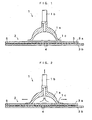
- FIG. 1 shows a vacuum suction pad 1 of a first conventional example for conveying a substrate for use in a vacuum suction device of the conveyor robot, and a liquid crystal panel 2, which is a laminated substrate formed by bonding substrates to be sucked together.
- the liquid crystal panel 2 is formed in such a manner that, after two glass substrates 3a and 3b are superposed with particulate spacers 4 interposed therebetween, peripheral edges of the glass substrates 3a and 3b are fixed by using an adhesive (sealant) 5, followed by injection of liquid crystal through a pore provided in a layer of the adhesive (sealant) 5.
- the vacuum suction pad 1 includes a rubber suction disk 1a formed like an upside down bowl and a suction tube 1b provided in a penetrating position through the top of the suction disk 1a.
- Fig. 2 shows a state where a lower edge peripheral portion 1c of the suction disk 1a is brought into press-contact with an upper surface of the liquid crystal panel 2 to perform vacuum suction through the suction tube 1b.
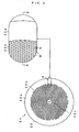
- a vacuum-sucked place of the upper glass substrate 3a might be locally deformed upward to cause an increase in a gap between the upper and lower glass substrates in this place, thereby temporally lowering pressure.
- the liquid crystal flows, as if concentrated, into this place.
- the spacers 4 with a diameter of, for example, 5 to 10 ⁇ m are inserted so as to have a uniform density of about 100 particles/mm 2 .
- the spacers 4 move along with the movement of the liquid crystal.
- this spacer-free type liquid crystal panel is vacuum-sucked by the suction disk 1a, the upper glass substrate 3a is locally deformed upward, and once deformed, it does not changed back into the original form, thereby causing variations in the gap between the upper and lower glass substrates. If the gap between the upper and lower glass substrates of the liquid crystal panel varies by 0.04 mm or more, a color shading appears on the display surface, with which the liquid crystal panel becomes defective as a product.
- the deformation of the upper glass substrate occurs when the vacuum suction pad 1 vacuum-sucks the liquid crystal panel 2, caused by too large a diameter of the suction disk 1a as compared to the thickness of the glass substrate and the size of the spacer 4.
- the diameter of the suction disk 1a is several tens of mm while the thickness of the glass substrate is 0.5 to 1.1 mm, and a thin glass substrate tends to be selected.
- suction force becomes insufficient if the size of the suction disk 1a is reduced for the purpose of avoiding the problems of the local deformation of the suction surface of the glass substrate, the variations in the gap between the glass substrates due to the suction by the vacuum suction pad 1 and the problem of the dispersion in the distribution, which results from the local deformation and the variations in the gap, of the spacers 4.
- the liquid crystal panel 2 is conveyed while imperfectly sucked, whereby the liquid crystal panel 2 might drop when conveyed, or might be pressed by the vacuum suction pad 1 when sucked to cause occurrence of variations in the gap between the upper and lower glass substrates, leading to occurrence of product defect.
- FIG. 5 is an exploded view showing a structure of a vacuum suction pad 21 in a second conventional example, shown in JP-A 11-019838 .
- a suction disk 22 of the vacuum suction pad 21 is formed into a disk shape and is made of a photosensitive resin material, a central portion of which is provided with a vertically penetrating suction port 22c, and a suction surface of the suction disk 22 is provided with a large number of protruded portions and recessed portions, as described later. These large number of protruded portions and recessed portions are formed by etching the photosensitive resin material.
- Fig. 6 shows the structure of the suction surface of the suction disk 22 in the vacuum suction pad 21, and Fig. 7 shows a cross-sectional view of the vacuum suction pad 21.
- the suction disk 22 has an airtight part 22a at a peripheral portion thereof with a flat surface, and a suction part 22b where a large number of protruded portions and recessed portions are formed.
- a reinforcement layer 23 is a layer made of a large rigid plate material so as to prevent the photosensitive resin material from being deformed due to an external stress, and is bonded to the photosensitive resin material in the stage of manufacturing the photosensitive resin material into a plate-making material.
- a magnet sheet 24 is a sheet with the same diameter as that of the suction disk 22.
- a double-faced adhesive sheet 25 is an adhesive sheet for joining the magnet sheet 24 and the reinforcement sheet 23 together, and has the same diameter as that of the suction part 22b on the suction disk 22.
- a hole Q is formed in a position corresponding to the suction port 22c, in each of those members 23 to 25.
- Fig. 7 shows an example where the diameter of the double-faced adhesive sheet 25 is made equivalent to that of the suction disk 22, and in this case, the whole surface of the suction disk 22 is fixed to the supporting member 26.
- the airtight part 22a is a region where the photosensitive resin material is not etched.
- the suction part 22b a large number of small-circular regions are non-etching portions (protruded portions) and the regions other than the protruded portions are etching portions (recessed portions).
- the small circular places are left as protruded portions M and the other places become recessed portions N.
- the protruded portions M and the airtight part 22a are both non-etching portions and thus positioned on the same surface.
- the supporting member 26 is an iron material having the same diameter as that of the magnet sheet 24, and a supporting part 26a is integrally formed at a central portion corresponding to the suction port 22c of the suction disk 22.
- a suction tube 27 is inserted through the supporting part 26a and is connected to a vacuum pump (not shown).
- the suction disk 22 is integrally joined with the reinforcement layer 23, the double-faced adhesive sheet 25 and the magnet sheet 24, and is made attachable to/detachable from the supporting member 26 by the action of the magnet sheet 24.
- the recessed portions N in the suction part 22b on the suction disk 22 form closed spaces with the airtight part 22a, and since the protruded portions M are independent of one another, the suction port 22c of the suction disk 22 is communicated with the closed spaces as shown in Fig. 5 , whereby the vacuum suction is performed using the foregoing vacuum pump (not shown) through the suction port 22c, allowing the suction disk 22 to be sucked to the liquid crystal panel 2.
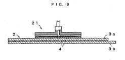
- Fig. 9 is a cross-sectional view showing a state of sucking a liquid crystal panel 2 having a small outer shape with the use of the foregoing vacuum suction pad 21 of the second conventional example.
- one vacuum suction pad 21 is used for the vacuum suction device to be installed in a conveyor robot or the like, and the size of the liquid crystal panel 2 is in such a degree as to be slightly larger than that of the vacuum suction pad 21.
- the vacuum suction pad 21 may be a vacuum suction pad of the type obtained by fixing the whole surface of the suction disk 22 with the double-faced adhesive sheet 25, as shown in Fig. 8 .
- a mother liquid crystal panel is segmented to manufacture a plurality of liquid crystal panels of a prescribed size.
- An example of such a panel is a liquid crystal panel to be used for mobile phones, personal digital assistances (PDAs) and the like.
- PDAs personal digital assistances
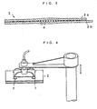
- a plurality of vacuum suction pads are used as in the vacuum suction devices shown in Fig. 4 .
- the vacuum suction pad 1 of the first conventional example is used as shown in Fig. 4 , as described above, in the liquid crystal panel, the local deformation of the upper glass substrate occurs and dispersion in the distribution of the foregoing spacers occurs caused by the local deformation, to bring about occurrence of product defect. For this reason, the vacuum suction pad 21 of the second conventional example is used.
- a distance (clearance) at which the vacuum suction pad can suck the liquid crystal panel There exists a distance (clearance) at which the vacuum suction pad can suck the liquid crystal panel.
- the vacuum suction pad 21 having the structure shown in Fig. 5 , air is discharged through the suction tube 27. At this time, the vacuum suction pad 21 sucks the air in front thereof so as to suck the liquid crystal panel.
- a distance from the surface of the upper glass substrate in the liquid crystal panel to the suction disk 22 of the vacuum suction pad 21 at this time is referred to as a clearance at which the suction is possible.
- the conventional clearance is 0.0 to 0.3 mm, and since the adequate range is very narrow, it has been very difficult to maintain the clearance and also to adjust the same.
- any one of the plurality of vacuum suction pads 21 cannot suck the liquid crystal panel 2 in a regular state, and the liquid crystal panel 2 is conveyed while imperfectly sucked, which might result in that the liquid crystal panel 2 drops when conveyed, or since the vacuum suction pad 21 presses the liquid crystal panel 2 in sucking the liquid crystal panel 2, the upper glass substrate in the liquid crystal panel 2 is locally deformed to lead to occurrence of variations in the gap between the upper and lower glass substrates.
- the present invention has been made to solve the above-mentioned problems, and an object thereof is to provide a vacuum suction head, comprising a vacuum suction pad which can hold a substrate being swollen or bent without making the substrate defective, widen a clearance between the vacuum suction pad and the substrate at which the suction is possible during the suction, and prevent local deformation of the substrate due to the suction as well as preventing occurrence of variations in the gap between the upper and lower glass substrates caused by the local deformation in the case of the laminated substrate such as a liquid crystal panel.
- EP-A-1 088 624 discloses a vacuum suction head according the preamble of claim 1.
- the present invention provides a vacuum suction head for vacuum-sucking a substrate, comprising: the features of claim 1.
- the elastic member may be a skirt pad formed into a skirt shape, and include: a plate part which supports the vacuum suction pad from behind a suction surface; an annular part which is formed into a thick annular shape on an outer edge of the plate part so as to surround a peripheral portion of the vacuum suction pad via a prescribed gap; and a skirt part which is formed into a conically annular shape by making a thickness of the skirt part smaller than that of a peripheral portion of the annular part.
- This skirt pad may communicate the outside of the annular part with the inside space, and provide a slit in the annular part, for leaking air from the outside into the inside space when there is a large a difference in pressure between the outside and the inside space.
- the elastic member may be a cylindrically formed sponge pad, and the elastic member may be formed into a cylindrical shape using an open foam sponge member so as to block a peripheral space of the vacuum suction pad from outside air when the vacuum suction pad comes close to the substrate to be sucked, and leak air from the outside into the inside when there is a difference in pressure between the outside and the inside space in the blocked state.
- the suction part of the vacuum suction pad may be formed on one surface of an etchable plate-shaped member by forming a large number of independent protruded portions and recessed portions by etching, and the airtight part may be annularly formed on the peripheral portion of the plate-shaped member as a non-etching region.
- the vacuum suction pad may be made of a photosensitive resin material which can be selectively etched with the use of ultraviolet irradiation and a solvent.
- a vacuum suction head in Embodiment 1 of the present invention will be described with reference to the drawings.
- a substrate herein means a single-plate semiconductor wafer, a ceramic substrate, a glass substrate, a plastic substrate, a transmissive-type projector substrate which is a laminated substrate, PDP (plasma display) which is a flat panel display, a reflective-type liquid projector substrate, a liquid crystal panel, an organic EL element substrate and the like. While the vacuum suction head of the present invention is effectively applicable to a liquid crystal panel and a mother liquid crystal panel with no spacer inserted therein, an example of a liquid crystal panel with spacers inserted therein will be described herein.
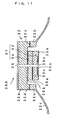
- FIG. 11 is an end view showing a structure of a vacuum suction head 30A in Embodiment 1.
- the vacuum suction head 30A includes a vacuum suction pad 31 and a skirt pad 32.
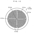
- Fig. 12 is a plan view showing a structure of a suction surface (suction disk 33) of the vacuum suction pad 31.
- the vacuum suction pad 31 has a similar structure to the structure of the vacuum suction pad shown in Figs. 6 and 7 , which is a multilayer structure where a suction disk 33 and a reinforcement layer 34 are joined with a double-faced adhesive sheet 35a.
- the suction disk 33 has an airtight part 33a on a peripheral flat surface and a suction part 33b where a larger number of protruded portions and recessed portions are formed.
- the suction disk 33 is formed into a disk shape and is made of a photosensitive resin material, a central portion of which is provided with an opening 33d as part of a vertically penetrating suction port 36.
- the large number of protruded portions and recessed portions in the suction part 33b are formed by etching the photosensitive resin material.
- the photosensitive resin material AFP as a printing plate material is used, for example. In this AFP, protruded portions and recessed portions can be selectively formed with the use of ultraviolet irradiation and a solvent.
- the material for the suction disk 33 is not restricted to the printing plate material so long as being a photosensitive resin material. Metal plates, ceramic and the like can also be etched, and if a similar processing method to this etching is applicable, such a method may be employed.
- a film with a desired pattern printed thereon is bonded as a mask to the surface of a sheet-shaped photosensitive resin plate.
- the bonded film is irradiated with (exposed to) ultraviolet rays, and thereafter, the photosensitive resin is etched (developed) with a treatment liquid.
- places other than the patterned places are etched to form recessed portions whereas the patterned places through which no light is transmitted are not etched to be left as protruded portions.
- the distribution density of the protruded portions is from 10 to 250 mesh/inch 2 , and the sizes of the individual protruding portions are set such that the area ratio of the whole protruded portions to the suction part 33b is from 10 to 50%. Further, the depth of the recessed portion (etched depth) is sufficiently large when it is from tens of ⁇ m to hundreds of ⁇ m. It should be noted that the shape of the protruded portions is not restricted to a circle, and an arbitrary shape, such as a polygon, may also be applied.
- the airtight part 33a is a region of the photosensitive resin material which is not etched.
- the inner circumferential side of the airtight part 33a is provided with an annular groove 33c as another recessed portion.
- the center of the suction disk 33 is provided with the opening 33d, through which a cross-shaped groove 33e is formed. These grooves are communicated with the opening 33d and serve as passages when air present in the recessed portions is discharged.
- the reinforcement layer 34 is a layer bonded to the suction disk 33 so as to prevent deformation of the photosensitive resin material constituting the suction disk 33 due to an external stress. This layer is bonded via a double-faced adhesive sheet 35a in the stage of manufacturing the photosensitive resin material into a plate-making material. The central portion of the reinforcement layer 34 is also provided with an opening.
- the skirt pad 32 is an elastic member newly provided in the present invention, which is rubber obtained by integral formation of a plate part 32a, an annular part 32b and a skirt part 32c.
- the plate part 32a is a disk-shaped holding member for holding the vacuum suction pad 31 via a double-faced adhesive sheet 35b, and the diameter thereof is sufficiently larger than the outer diameter of the vacuum suction pad 31.
- the center of the plate part 32a is also provided with an opening, which is communicated with the opening of the vacuum suction pad 31 to form the suction port 36.
- the annular part 32b is formed thick and annularly on the outer edge of the plate part 32a so as to surround the vacuum suction pad 31 at a prescribed spacing, and the lower surface of the annular part 32b is formed in a position higher than the lower surface of the vacuum suction pad 31 such that the vacuum suction pad 31 protrudes downward from the annular part 32b.
- the skirt part 32c is a thin annular rubber member conically expanded, with the annular part 32b as the root, in the direction facing the substrate.
- This rubber member includes nitrile rubber.
- the skirt pad 32 serves to widen the air-discharging space on the periphery of the suction part when sucking the substrate, so as to widen the clearance between the vacuum suction pad 31 and the substrate at which the suction is possible. Since the skirt part 32c is thin, when the vacuum suction head 30A is brought close to the substrate, the peripheral portion of the vacuum suction head 30A is brought into contact with the substrate to be elastically deformed. As thus described, the skirt part 32c of the skirt pad 32 exerts a sealing function of blocking the air flowing in from the outside by the contact with the substrate.
- a slit 32d is a cut provided in the annular part 32b so as to leak the air between the outside and the inside of the skirt.
- This slit 32d can be realized by making a cut with the use of a thin blade in part of the side surface of the skirt pad 32 after formation.
- the slit 32d is not restricted to this formation method and shape.
- the slit 32d may be a through hole small enough to hold the inside space in a negative pressure state after the skirt pad 32 comes into contact with the glass substrate till the vacuum suction pad 31 comes into contact with the substrate, and not to interfere with the suction of the substrate by the vacuum suction pad 31, and may for example be a round hole with a microdiameter.
- the lower surface of the annular part 32b is positioned higher than the lower surface of the vacuum suction pad 31 such that the vacuum suction pad 31 protrudes downward from the annular part 32b.
- the annular part 32b does not come into contact with the liquid crystal panel 2 even when the vacuum suction pad 31 comes into contact with the liquid crystal panel 2. This can prevent deformation of the annular part 32b to close the slit 32d.
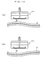
- FIG. 13 is a cross-sectional view showing a state where the vacuum suction head 30B sucks the liquid crystal panel 2.
- the liquid crystal panel 2 is in a state where a constant gap is held between the upper glass substrate 3a and the lower glass substrate 3b via spacers S.
- the vacuum suction head 30B is brought close to the liquid crystal panel 2 and air is discharged from the suction port 36, as shown in the figure, the skirt part 32c adheres to the liquid crystal panel 2 and the space covered with the skirt part 32c is held in a negative pressure state.
- the suction disk 33 also adheres to the liquid crystal panel 2 and the air is further discharged to act suction force upon the liquid crystal panel 2.
- a space V1 generates since the vacuum suction pad 31 is positioned lower than the lower end of the annular part 32b and the lower surface of the annular part 32b as the root of the skirt part 32c is positioned higher than the lower surface of the vacuum suction pad 31.
- the space V1 is formed of a spacing between the vacuum suction pad 31 and the annular part 32b, and the space V1 becomes even wider when the difference between the outer diameter of the vacuum suction pad 31 and the inner diameter of the annular part 32b is large.
- the glass substrates 3a and 3b have a thickness as thin as 0.5 to 1.1 mm, and when the negative pressure is acted thereon, the upper glass substrate 3a is locally deformed upward in portions x1 and x2, as shown in Fig. 13 .
- the gap between the upper glass substrate 3a and the lower glass substrate 3b widens, and the spacers S then move to the portions x1 and x2 where the gap has widened.
- a liquid crystal panel of Fig. 13 of the type with no spacer S inserted between the upper and lower glass substrates in the liquid crystal panel 2.
- this spacer-free type liquid crystal panel is vacuum-sucked by a suction head 30B, the upper glass substrate 3a is locally deformed upward and once deformed, it does not returns to the original state, to cause occurrence of variations in the gap between the upper and lower glass substrates, thereby leading to appearance of a color shading on the display surface, and hence the liquid crystal panel becomes defective as a product.
- the skirt pad 32 is provided with the slit 32d for air-inspiration.
- the vacuum suction pad 31 is provided so as to protrude downward from the annular part 32b such that the annular part 32b is prevented from being deformed to close the slit 32d even with the vacuum suction pad 31 brought into contact with the liquid crystal panel 2. Therefore the lower surface of the annular part 32b is positioned higher than the lower surface of the vacuum suction pad 31.
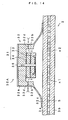
- Fig. 14 shows a transitional state of sucking the liquid crystal panel by the vacuum suction head 30A
- Fig. 15 shows a steady sucking state.
- the skirt part 32c When the air is discharged through the suction port 36 to suck the liquid crystal panel 2, as shown in Fig. 14 , first, the skirt part 32c is brought into contact with the liquid crystal panel 2. When the air continues to be discharged in this state, the pressure in the space covered with the skirt part 32c and the upper glass substrate 3a becomes negative. This causes elastic deformation of the skirt part 32c to increase a contact area between the skirt part 32c and the upper glass substrate 3a. Further, since the negative pressure inside the skirt part 32c becomes larger, the air begins to be leaked from the outside through the slit 32d.
- the distance at which suction is possible becomes longer than that in the conventional example, and in one example, the distance was from 0.0 to 2.0 mm. Therefore, even with the brittle material substrate swollen or bent in some degree, it was possible for the suction disk 33 to follow so as to hold the substrate with certainty.
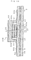
- Fig. 16 is an end view showing a structure of a vacuum suction head 40 in Embodiment 2.
- the vacuum suction head 40 includes the vacuum suction pad 31, a plate part 41 and a sponge pad 42.
- the vacuum suction pad 31 and the sponge pad 42 are concentrically attached to the plate part 41.
- the sponge pad 42 is an elastic member having the same function as the skirt pad 32 shown in Fig. 11 .
- the sponge pad 42 is made of porous rubber and is cylindrically formed. As the porous rubber, especially one with large loss of pressure is used. Used herein is a sponge body of EPT (Ethylene Propylene Terpolymer) which is excellent in weather resistance, heat resistance and aging resistance. As the sponge body, an open-cell foamed type with a desired pressure loss is preferably used.
- the height of the sponge pad 42 in the z direction in a non-deformed state is slightly larger than the thickness of the vacuum suction pad 31 in the z direction.
- the center axis of the vacuum suction pad 31 is provided with a suction port 43.
- Fig. 17 shows a transitional state of sucking the liquid crystal panel 2 by the vacuum suction head 40
- Fig. 18 shows a steady sucking state.
- the flowing of the air inside does not cause a decrease in negative pressure of the closed space in such a degree as to prevent the vacuum suction pad 31 from sucking the liquid crystal panel 2.
- the liquid crystal panel 2 is further sucked by the vacuum suction pad 31, and as shown in Fig. 18 , the suction disk 33 of the vacuum suction pad 31 is brought into contact with the liquid crystal panel 2.
- the suction disk 33 has negative pressure upon the upper glass substrate 3a large enough to singly suck and hold the liquid crystal panel 2.
- the outside air is flown into a space V2 between the sponge pad 42 and the vacuum suction pad 31 due to the difference between the outside pressure and the inside pressure of the sponge pad 42, and thereby the negative pressure of the space V2 is instantly eliminated. Therefore, the upper glass substrate 3a in this portion is no longer locally deformed upward. Accordingly, the spacers S do not move, and it is thus possible to suck and hold the liquid crystal panel 2 with certainty while holding the gap between the glass substrates in a uniform state.
- the distance at which the suction is possible becomes longer than that in the conventional example.
- the distance was from 0.0 to 2.0 mm, and even with the brittle material substrate swollen or bent in some degree, it has become possible for the suction disk 33 to follow so as to hold the brittle material substrate with certainty.
- the vacuum suction head of the present invention is effectively applicable to a single-plate semiconductor wafer, a ceramic substrate, a glass substrate, a plastic substrate, a transmissive-type projector substrate which is a laminated substrate, a reflective-type liquid projector substrate, a plasma display panel (PDP) which is a flat panel display, a liquid crystal panel, an organic EL element substrate, and the like, since the vacuum suction head can suck these substrates without causing local deformation thereof.
- PDP plasma display panel
- the vacuum suction head of the present invention is effectively applicable also to a liquid crystal panel and a mother liquid crystal panel with no spacer inserted therein.
- the elastic member is provided with the peripheral portion of the suction disk, it is possible to promptly and stably make the pressure negative on the periphery of the suction disk immediately before the suction of the substrate. Subsequently, as the suction disk adheres to the substrate, the substrate is held such that the suction force of the suction disk on the substrate further increases. In such a manner, a clearance at which the substrate can be sucked by the suction disk (i.e. clearance between the substrate and the suction surface of the suction disk) widens, thereby preventing occurrence of defective suction when a substrate having a large shape is sucked using a plurality of suction disks.
- a vacuum suction head is preferably applicable to a substrate scribing device and a substrate conveying device.
Abstract
Description
- The present invention relates to a vacuum suction head for holding and sucking a substrate when conveyed. The substrate herein means a single-plate semiconductor wafer, a ceramic substrate, a glass substrate, a plastic substrate, a transmissive-type projector substrate which is a laminated substrate, PDP (plasma display) which is a flat panel display, a reflective-type liquid crystal projector substrate, a liquid crystal panel, an organic EL element substrate, and the like. Herein, a glass substrate and the like having a small thickness are called brittle material substrates. In the following, description will be given using the liquid crystal panel as an example.
- A conveyor robot or the like is used for supplying and removing a material to and from a substrate processing device and the like.
Fig. 1 shows avacuum suction pad 1 of a first conventional example for conveying a substrate for use in a vacuum suction device of the conveyor robot, and aliquid crystal panel 2, which is a laminated substrate formed by bonding substrates to be sucked together. As is well known, theliquid crystal panel 2 is formed in such a manner that, after two glass substrates 3a and 3b are superposed withparticulate spacers 4 interposed therebetween, peripheral edges of the glass substrates 3a and 3b are fixed by using an adhesive (sealant) 5, followed by injection of liquid crystal through a pore provided in a layer of the adhesive (sealant) 5. Thevacuum suction pad 1 includes a rubber suction disk 1a formed like an upside down bowl and a suction tube 1b provided in a penetrating position through the top of the suction disk 1a. -
Fig. 2 shows a state where a lower edge peripheral portion 1c of the suction disk 1a is brought into press-contact with an upper surface of theliquid crystal panel 2 to perform vacuum suction through the suction tube 1b. By this vacuum suction, a vacuum-sucked place of the upper glass substrate 3a might be locally deformed upward to cause an increase in a gap between the upper and lower glass substrates in this place, thereby temporally lowering pressure. In this case, the liquid crystal flows, as if concentrated, into this place. Thespacers 4 with a diameter of, for example, 5 to 10 µm are inserted so as to have a uniform density of about 100 particles/mm2. However, being unfixed to the glass substrates 3a and 3b, thespacers 4 move along with the movement of the liquid crystal. When no liquid crystal has been injected into theliquid crystal panel 2, air flow into a place where pressure has been lowered. In this case, because the resistance to the movement of thespacers 4 is small, the movement of thespacers 4 is further contributed. - Consequently, after the suction by the
vacuum suction pad 1, dispersion in the distribution of thespacers 4 has occurred, and corresponding to this dispersion, variations in the gap between the upper and lower glass substrates have occurred, as shown inFig. 3 . Further, although not shown in the figure, there recently exists a liquid crystal panel of the type obtained by bonding two glass substrates together without spacers, and this spacer-free type liquid crystal panel is configured in a state where thespacers 4 are not inserted into theliquid crystal panel 2 inFigs. 1 to 3 . Also in the case this spacer-free type liquid crystal panel is vacuum-sucked by the suction disk 1a, the upper glass substrate 3a is locally deformed upward, and once deformed, it does not changed back into the original form, thereby causing variations in the gap between the upper and lower glass substrates. If the gap between the upper and lower glass substrates of the liquid crystal panel varies by 0.04 mm or more, a color shading appears on the display surface, with which the liquid crystal panel becomes defective as a product. - As thus described, in the first conventional example, the deformation of the upper glass substrate occurs when the
vacuum suction pad 1 vacuum-sucks theliquid crystal panel 2, caused by too large a diameter of the suction disk 1a as compared to the thickness of the glass substrate and the size of thespacer 4. The diameter of the suction disk 1a is several tens of mm while the thickness of the glass substrate is 0.5 to 1.1 mm, and a thin glass substrate tends to be selected. - In the
vacuum suction pad 1 ofFig 1 , suction force becomes insufficient if the size of the suction disk 1a is reduced for the purpose of avoiding the problems of the local deformation of the suction surface of the glass substrate, the variations in the gap between the glass substrates due to the suction by thevacuum suction pad 1 and the problem of the dispersion in the distribution, which results from the local deformation and the variations in the gap, of thespacers 4. To this end, as shown inFig. 4 , there is a method for providing a plurality ofvacuum suction pads 1 each having a small suction disk to suck theliquid crystal panel 2. In this case, it is necessary to attach all thevacuum suction pads 1 to the vacuum suction device such that the suction surface of each of thevacuum suction pads 1 is provided within a prescribed attachment tolerance range in order to prevent thevacuum suction pads 1 from pressing the glass substrate surface. Further, also in the case theliquid crystal panel 2 to be sucked is swollen or bent, it is necessary to set the suction surface of each of thevacuum suction pads 1 within a clearance at which the suction of theliquid crystal panel 2 is possible. - If the plurality of
vacuum suction pads 1 are attached to the vacuum suction device with the suction surfaces thereof out of the above-mentioned attachment tolerance range, theliquid crystal panel 2 is conveyed while imperfectly sucked, whereby theliquid crystal panel 2 might drop when conveyed, or might be pressed by thevacuum suction pad 1 when sucked to cause occurrence of variations in the gap between the upper and lower glass substrates, leading to occurrence of product defect. -
Fig. 5 is an exploded view showing a structure of avacuum suction pad 21 in a second conventional example, shown inJP-A 11-019838 suction disk 22 of thevacuum suction pad 21 is formed into a disk shape and is made of a photosensitive resin material, a central portion of which is provided with a vertically penetrating suction port 22c, and a suction surface of thesuction disk 22 is provided with a large number of protruded portions and recessed portions, as described later. These large number of protruded portions and recessed portions are formed by etching the photosensitive resin material. -
Fig. 6 shows the structure of the suction surface of thesuction disk 22 in thevacuum suction pad 21, andFig. 7 shows a cross-sectional view of thevacuum suction pad 21. Thesuction disk 22 has an airtight part 22a at a peripheral portion thereof with a flat surface, and a suction part 22b where a large number of protruded portions and recessed portions are formed. As shown inFig. 7 , areinforcement layer 23 is a layer made of a large rigid plate material so as to prevent the photosensitive resin material from being deformed due to an external stress, and is bonded to the photosensitive resin material in the stage of manufacturing the photosensitive resin material into a plate-making material. Amagnet sheet 24 is a sheet with the same diameter as that of thesuction disk 22. A double-facedadhesive sheet 25 is an adhesive sheet for joining themagnet sheet 24 and thereinforcement sheet 23 together, and has the same diameter as that of the suction part 22b on thesuction disk 22. A hole Q is formed in a position corresponding to the suction port 22c, in each of thosemembers 23 to 25. - In the case of making the diameter of the double-faced
adhesive sheet 25 equivalent to the diameter of the suction part 22b, as shown inFig. 7 , only the suction part 22b on thesuction disk 22 is fixed to a supportingmember 26 via themagnet sheet 24. Meanwhile, the airtight part 22a is not fixed and stays free.Fig. 8 shows an example where the diameter of the double-facedadhesive sheet 25 is made equivalent to that of thesuction disk 22, and in this case, the whole surface of thesuction disk 22 is fixed to the supportingmember 26. - Turning back to
Fig. 6 , an expanded view X of the peripheral portion of thesuction disk 22 is referred to. The airtight part 22a is a region where the photosensitive resin material is not etched. In the suction part 22b, a large number of small-circular regions are non-etching portions (protruded portions) and the regions other than the protruded portions are etching portions (recessed portions). As shown in the expanded view X inFig. 6 , the small circular places are left as protruded portions M and the other places become recessed portions N. Herein, the protruded portions M and the airtight part 22a are both non-etching portions and thus positioned on the same surface. - The supporting
member 26 is an iron material having the same diameter as that of themagnet sheet 24, and a supporting part 26a is integrally formed at a central portion corresponding to the suction port 22c of thesuction disk 22. Asuction tube 27 is inserted through the supporting part 26a and is connected to a vacuum pump (not shown). Thesuction disk 22 is integrally joined with thereinforcement layer 23, the double-facedadhesive sheet 25 and themagnet sheet 24, and is made attachable to/detachable from the supportingmember 26 by the action of themagnet sheet 24. - When the
vacuum suction pad 21 as thus configured is brought into press-contact with the flatliquid crystal panel 2, the recessed portions N in the suction part 22b on thesuction disk 22 form closed spaces with the airtight part 22a, and since the protruded portions M are independent of one another, the suction port 22c of thesuction disk 22 is communicated with the closed spaces as shown inFig. 5 , whereby the vacuum suction is performed using the foregoing vacuum pump (not shown) through the suction port 22c, allowing thesuction disk 22 to be sucked to theliquid crystal panel 2. -
Fig. 9 is a cross-sectional view showing a state of sucking aliquid crystal panel 2 having a small outer shape with the use of the foregoingvacuum suction pad 21 of the second conventional example. In this case, in order to hold the substrate, onevacuum suction pad 21 is used for the vacuum suction device to be installed in a conveyor robot or the like, and the size of theliquid crystal panel 2 is in such a degree as to be slightly larger than that of thevacuum suction pad 21. When theliquid crystal panel 2 is made to be sucked by thevacuum suction pad 21, the large number of protruded portions M formed on the same surface as the airtight part 22a in the expanded view X ofFig. 6 are brought into contact with the upper surface of the upper glass substrate 3a in theliquid crystal panel 2, which can prevent local deformation of the upper glass substrate 3a in theliquid crystal panel 2, and hence variations in the gap between the upper glass substrate 3a and the lower glass substrate 3b does not occur. Moreover, also in the case of the liquid crystal panel of which the gap is formed without insertion of the spacers, no variations in the gap between the upper and lower glass substrates occur. It should be noted that, in the case thesuction disk 22 itself is sufficiently flexible, thevacuum suction pad 21 may be a vacuum suction pad of the type obtained by fixing the whole surface of thesuction disk 22 with the double-facedadhesive sheet 25, as shown inFig. 8 . - In the case the liquid crystal panel for use in individual display devices has a small shape, a mother liquid crystal panel is segmented to manufacture a plurality of liquid crystal panels of a prescribed size. An example of such a panel is a liquid crystal panel to be used for mobile phones, personal digital assistances (PDAs) and the like. On the other hand, in the case of a liquid crystal panel having a large outer shape, a plurality of vacuum suction pads are used as in the vacuum suction devices shown in
Fig. 4 . - In the case one vacuum suction device is provided with a plurality of vacuum suction pads, when the
vacuum suction pad 1 of the first conventional example is used as shown inFig. 4 , as described above, in the liquid crystal panel, the local deformation of the upper glass substrate occurs and dispersion in the distribution of the foregoing spacers occurs caused by the local deformation, to bring about occurrence of product defect. For this reason, thevacuum suction pad 21 of the second conventional example is used. - There exists a distance (clearance) at which the vacuum suction pad can suck the liquid crystal panel. In the
vacuum suction pad 21 having the structure shown inFig. 5 , air is discharged through thesuction tube 27. At this time, thevacuum suction pad 21 sucks the air in front thereof so as to suck the liquid crystal panel. A distance from the surface of the upper glass substrate in the liquid crystal panel to thesuction disk 22 of thevacuum suction pad 21 at this time is referred to as a clearance at which the suction is possible. The conventional clearance is 0.0 to 0.3 mm, and since the adequate range is very narrow, it has been very difficult to maintain the clearance and also to adjust the same. - As shown in
Figs. 10(a) and (b) , with theliquid crystal panel 2 swollen or bent, even if a plurality ofvacuum suction pads 21 are provided in the vacuum suction device within a prescribed attachment tolerance range, there have been cases where the clearance G between the upper surface of theliquid crystal panel 2 and thevacuum suction pad 21 exceed the clearance at which the suction of thevacuum suction pad 21 is possible. In such a case, any one of the plurality ofvacuum suction pads 21 cannot suck theliquid crystal panel 2 in a regular state, and theliquid crystal panel 2 is conveyed while imperfectly sucked, which might result in that theliquid crystal panel 2 drops when conveyed, or since thevacuum suction pad 21 presses theliquid crystal panel 2 in sucking theliquid crystal panel 2, the upper glass substrate in theliquid crystal panel 2 is locally deformed to lead to occurrence of variations in the gap between the upper and lower glass substrates. - The present invention has been made to solve the above-mentioned problems, and an object thereof is to provide a vacuum suction head, comprising a vacuum suction pad which can hold a substrate being swollen or bent without making the substrate defective, widen a clearance between the vacuum suction pad and the substrate at which the suction is possible during the suction, and prevent local deformation of the substrate due to the suction as well as preventing occurrence of variations in the gap between the upper and lower glass substrates caused by the local deformation in the case of the laminated substrate such as a liquid crystal panel.
-
EP-A-1 088 624 discloses a vacuum suction head according the preamble ofclaim 1. - The present invention provides a vacuum suction head for vacuum-sucking a substrate, comprising: the features of
claim 1. - Herein, the elastic member may be a skirt pad formed into a skirt shape, and include: a plate part which supports the vacuum suction pad from behind a suction surface; an annular part which is formed into a thick annular shape on an outer edge of the plate part so as to surround a peripheral portion of the vacuum suction pad via a prescribed gap; and a skirt part which is formed into a conically annular shape by making a thickness of the skirt part smaller than that of a peripheral portion of the annular part.
- This skirt pad may communicate the outside of the annular part with the inside space, and provide a slit in the annular part, for leaking air from the outside into the inside space when there is a large a difference in pressure between the outside and the inside space.
- Further, the elastic member may be a cylindrically formed sponge pad, and the elastic member may be formed into a cylindrical shape using an open foam sponge member so as to block a peripheral space of the vacuum suction pad from outside air when the vacuum suction pad comes close to the substrate to be sucked, and leak air from the outside into the inside when there is a difference in pressure between the outside and the inside space in the blocked state.
- The suction part of the vacuum suction pad may be formed on one surface of an etchable plate-shaped member by forming a large number of independent protruded portions and recessed portions by etching, and the airtight part may be annularly formed on the peripheral portion of the plate-shaped member as a non-etching region.
- The vacuum suction pad may be made of a photosensitive resin material which can be selectively etched with the use of ultraviolet irradiation and a solvent.
-
-
Fig. 1 is a cross-sectional view showing a positional relation between a vacuum suction pad of a first conventional example and a liquid crystal panel which is a brittle material substrate to be sucked. -
Fig. 2 is a cross-sectional view showing a state where a lower edge peripheral portion of a suction disk is brought into press-contact with an upper surface of the liquid crystal panel to perform vacuum suction through a suction tube in the vacuum suction pad of the first conventional example. -
Fig. 3 is an explanatory view showing a state where dispersion in the distribution of spacers has occurred after suction and variations in the gap between glass substrates has also occurred according to the dispersion in the distribution in the case of using the vacuum suction pad of the first conventional example. -
Fig. 4 is an external view showing a configuration of a vacuum suction device of a conventional example provided with a plurality of vacuum suction pads. -
Fig. 5 is an exploded perspective view showing a structure of a vacuum suction pad in a second conventional example. -
Fig. 6 is a plan view of a suction disk of the vacuum suction pad of the second conventional example as seen from the below. -
Fig. 7 is a cross-sectional view showing the structure of the suction disk in the vacuum suction pad of the second conventional example. -
Fig. 8 is a cross-sectional view showing the case where a diameter of a double-faced adhesive sheet is made equivalent to the diameter of the suction disk in the vacuum suction pad of the second conventional example. -
Fig. 9 is a cross-sectional view showing a state where a liquid crystal panel having a small outer shape is sucked using the vacuum suction pad of the second conventional example. -
Figs. 10(a) and 10(b) are explanatory views each showing a clearance between the vacuum suction pad and a liquid crystal panel with a bent portion in the second conventional example. -
Fig. 11 is an end view showing a structure of a vacuum suction head inEmbodiment 1 of the present invention. -
Fig. 12 is a plan view of the structure of the suction surface of the vacuum suction head inEmbodiment 1 of the present invention. -
Fig. 13 is a cross-sectional view showing a state of sucking the liquid crystal panel when a slit-free vacuum suction head is used. -
Fig. 14 is a cross-sectional view showing a transitional state of sucking the liquid crystal panel when the vacuum suction head inEmbodiment 1 of the present invention is used. -
Fig. 15 is a cross-sectional view showing a state of sucking the liquid crystal panel when the vacuum suction head inEmbodiment 1 of the present invention is used. -
Fig. 16 is an end view showing a structure of a vacuum suction head inEmbodiment 2 of the present invention. -
Fig. 17 is a cross-sectional view showing a transitional state of sucking the liquid crystal panel when the vacuum suction head inEmbodiment 2 is used. -
Fig. 18 is a cross-sectional view showing a state of sucking the liquid crystal panel when the vacuum suction head inEmbodiment 2 is used. -
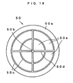
Fig. 19 is a plan view showing a structure of another suction disk for use in a vacuum suction head in each embodiment. - A vacuum suction head in
Embodiment 1 of the present invention will be described with reference to the drawings. A substrate herein means a single-plate semiconductor wafer, a ceramic substrate, a glass substrate, a plastic substrate, a transmissive-type projector substrate which is a laminated substrate, PDP (plasma display) which is a flat panel display, a reflective-type liquid projector substrate, a liquid crystal panel, an organic EL element substrate and the like. While the vacuum suction head of the present invention is effectively applicable to a liquid crystal panel and a mother liquid crystal panel with no spacer inserted therein, an example of a liquid crystal panel with spacers inserted therein will be described herein.Fig. 11 is an end view showing a structure of a vacuum suction head 30A inEmbodiment 1. The vacuum suction head 30A includes avacuum suction pad 31 and askirt pad 32.Fig. 12 is a plan view showing a structure of a suction surface (suction disk 33) of thevacuum suction pad 31. - The
vacuum suction pad 31 has a similar structure to the structure of the vacuum suction pad shown inFigs. 6 and7 , which is a multilayer structure where asuction disk 33 and areinforcement layer 34 are joined with a double-faced adhesive sheet 35a. Thesuction disk 33 has an airtight part 33a on a peripheral flat surface and a suction part 33b where a larger number of protruded portions and recessed portions are formed. - The
suction disk 33 is formed into a disk shape and is made of a photosensitive resin material, a central portion of which is provided with an opening 33d as part of a vertically penetratingsuction port 36. The large number of protruded portions and recessed portions in the suction part 33b are formed by etching the photosensitive resin material. As the photosensitive resin material, AFP as a printing plate material is used, for example. In this AFP, protruded portions and recessed portions can be selectively formed with the use of ultraviolet irradiation and a solvent. It should be noted that the material for thesuction disk 33 is not restricted to the printing plate material so long as being a photosensitive resin material. Metal plates, ceramic and the like can also be etched, and if a similar processing method to this etching is applicable, such a method may be employed. - In the case of using the photosensitive resin material, a film with a desired pattern printed thereon is bonded as a mask to the surface of a sheet-shaped photosensitive resin plate. The bonded film is irradiated with (exposed to) ultraviolet rays, and thereafter, the photosensitive resin is etched (developed) with a treatment liquid. In such a manner, places other than the patterned places are etched to form recessed portions whereas the patterned places through which no light is transmitted are not etched to be left as protruded portions.
- The distribution density of the protruded portions is from 10 to 250 mesh/inch2, and the sizes of the individual protruding portions are set such that the area ratio of the whole protruded portions to the suction part 33b is from 10 to 50%. Further, the depth of the recessed portion (etched depth) is sufficiently large when it is from tens of µm to hundreds of µm. It should be noted that the shape of the protruded portions is not restricted to a circle, and an arbitrary shape, such as a polygon, may also be applied.
- The airtight part 33a is a region of the photosensitive resin material which is not etched. Herein, since neither the protruded portions nor the airtight part 33a are etched, they are positioned on the same surface. Further, the inner circumferential side of the airtight part 33a is provided with an annular groove 33c as another recessed portion. Moreover, the center of the
suction disk 33 is provided with the opening 33d, through which a cross-shaped groove 33e is formed. These grooves are communicated with the opening 33d and serve as passages when air present in the recessed portions is discharged. - The
reinforcement layer 34 is a layer bonded to thesuction disk 33 so as to prevent deformation of the photosensitive resin material constituting thesuction disk 33 due to an external stress. This layer is bonded via a double-faced adhesive sheet 35a in the stage of manufacturing the photosensitive resin material into a plate-making material. The central portion of thereinforcement layer 34 is also provided with an opening. - The
skirt pad 32 is an elastic member newly provided in the present invention, which is rubber obtained by integral formation of a plate part 32a, an annular part 32b and a skirt part 32c. The plate part 32a is a disk-shaped holding member for holding thevacuum suction pad 31 via a double-faced adhesive sheet 35b, and the diameter thereof is sufficiently larger than the outer diameter of thevacuum suction pad 31. The center of the plate part 32a is also provided with an opening, which is communicated with the opening of thevacuum suction pad 31 to form thesuction port 36. The annular part 32b is formed thick and annularly on the outer edge of the plate part 32a so as to surround thevacuum suction pad 31 at a prescribed spacing, and the lower surface of the annular part 32b is formed in a position higher than the lower surface of thevacuum suction pad 31 such that thevacuum suction pad 31 protrudes downward from the annular part 32b. The skirt part 32c is a thin annular rubber member conically expanded, with the annular part 32b as the root, in the direction facing the substrate. An example of this rubber member includes nitrile rubber. - The
skirt pad 32 serves to widen the air-discharging space on the periphery of the suction part when sucking the substrate, so as to widen the clearance between thevacuum suction pad 31 and the substrate at which the suction is possible. Since the skirt part 32c is thin, when the vacuum suction head 30A is brought close to the substrate, the peripheral portion of the vacuum suction head 30A is brought into contact with the substrate to be elastically deformed. As thus described, the skirt part 32c of theskirt pad 32 exerts a sealing function of blocking the air flowing in from the outside by the contact with the substrate. - A slit 32d is a cut provided in the annular part 32b so as to leak the air between the outside and the inside of the skirt. This slit 32d can be realized by making a cut with the use of a thin blade in part of the side surface of the
skirt pad 32 after formation. - It is to be noted that the slit 32d is not restricted to this formation method and shape. The slit 32d may be a through hole small enough to hold the inside space in a negative pressure state after the
skirt pad 32 comes into contact with the glass substrate till thevacuum suction pad 31 comes into contact with the substrate, and not to interfere with the suction of the substrate by thevacuum suction pad 31, and may for example be a round hole with a microdiameter. - Further, the lower surface of the annular part 32b is positioned higher than the lower surface of the
vacuum suction pad 31 such that thevacuum suction pad 31 protrudes downward from the annular part 32b. Hence the annular part 32b does not come into contact with theliquid crystal panel 2 even when thevacuum suction pad 31 comes into contact with theliquid crystal panel 2. This can prevent deformation of the annular part 32b to close the slit 32d. - Herein, the function of the slit 32d will be further described. A vacuum suction head of the type without the slit 32d is referred to as a vacuum suction head 30B.
Fig. 13 is a cross-sectional view showing a state where the vacuum suction head 30B sucks theliquid crystal panel 2. As described above, theliquid crystal panel 2 is in a state where a constant gap is held between the upper glass substrate 3a and the lower glass substrate 3b via spacers S. When the vacuum suction head 30B is brought close to theliquid crystal panel 2 and air is discharged from thesuction port 36, as shown in the figure, the skirt part 32c adheres to theliquid crystal panel 2 and the space covered with the skirt part 32c is held in a negative pressure state. In course of time, thesuction disk 33 also adheres to theliquid crystal panel 2 and the air is further discharged to act suction force upon theliquid crystal panel 2. - A space V1 generates since the
vacuum suction pad 31 is positioned lower than the lower end of the annular part 32b and the lower surface of the annular part 32b as the root of the skirt part 32c is positioned higher than the lower surface of thevacuum suction pad 31. The space V1 is formed of a spacing between thevacuum suction pad 31 and the annular part 32b, and the space V1 becomes even wider when the difference between the outer diameter of thevacuum suction pad 31 and the inner diameter of the annular part 32b is large. As described in the conventional example, the glass substrates 3a and 3b have a thickness as thin as 0.5 to 1.1 mm, and when the negative pressure is acted thereon, the upper glass substrate 3a is locally deformed upward in portions x1 and x2, as shown inFig. 13 . In such a state, the gap between the upper glass substrate 3a and the lower glass substrate 3b widens, and the spacers S then move to the portions x1 and x2 where the gap has widened. Moreover, there exists a liquid crystal panel ofFig. 13 of the type with no spacer S inserted between the upper and lower glass substrates in theliquid crystal panel 2. Also in the case this spacer-free type liquid crystal panel is vacuum-sucked by a suction head 30B, the upper glass substrate 3a is locally deformed upward and once deformed, it does not returns to the original state, to cause occurrence of variations in the gap between the upper and lower glass substrates, thereby leading to appearance of a color shading on the display surface, and hence the liquid crystal panel becomes defective as a product. - In order to solve this problem, as shown in
Fig. 11 , theskirt pad 32 is provided with the slit 32d for air-inspiration. Thevacuum suction pad 31 is provided so as to protrude downward from the annular part 32b such that the annular part 32b is prevented from being deformed to close the slit 32d even with thevacuum suction pad 31 brought into contact with theliquid crystal panel 2. Therefore the lower surface of the annular part 32b is positioned higher than the lower surface of thevacuum suction pad 31.Fig. 14 shows a transitional state of sucking the liquid crystal panel by the vacuum suction head 30A, andFig. 15 shows a steady sucking state. - When the air is discharged through the
suction port 36 to suck theliquid crystal panel 2, as shown inFig. 14 , first, the skirt part 32c is brought into contact with theliquid crystal panel 2. When the air continues to be discharged in this state, the pressure in the space covered with the skirt part 32c and the upper glass substrate 3a becomes negative. This causes elastic deformation of the skirt part 32c to increase a contact area between the skirt part 32c and the upper glass substrate 3a. Further, since the negative pressure inside the skirt part 32c becomes larger, the air begins to be leaked from the outside through the slit 32d. - Although this causes decreased negative pressure on the periphery of the
suction disk 33, the negative pressure in such a degree does not prevent thevacuum suction pad 31 from sucking theliquid crystal panel 2, and theliquid crystal panel 2 is thus sucked by thevacuum suction pad 31. When the air-discharging further continues, as shown inFig. 15 , thesuction disk 33 of thevacuum suction pad 31 is brought into contact with theliquid crystal panel 2. In such a state, the negative pressure upon the upper glass substrate 3a of thesuction disk 33 further increases due to the sealing function of the airtight part 33a. Thesuction disk 33 thus comes into a state of being capable of singly sucking and holding theliquid crystal panel 2. Thereafter, the outside air is further leaked through the slit 32d into the space V1, to eliminate the negative pressure. When the suction is performed in such a manner, the pressure in the space V1 is kept almost equivalent to the outside pressure, and the upper glass substrate 3a is not locally deformed as inFig. 13 . Therefore, the spacers S do not move and it is thus possible to suck and hold theliquid crystal panel 2 while holding the gap between the glass substrates in a uniform state. - In the case a brittle material substrate having a large outer shape is sucked using a plurality of vacuum suction heads 30A with the structure thus described, the distance at which suction is possible becomes longer than that in the conventional example, and in one example, the distance was from 0.0 to 2.0 mm. Therefore, even with the brittle material substrate swollen or bent in some degree, it was possible for the
suction disk 33 to follow so as to hold the substrate with certainty. - Next, a vacuum suction head in
Embodiment 2 of the present invention will be described with reference to the drawings.Fig. 16 is an end view showing a structure of avacuum suction head 40 inEmbodiment 2. Thevacuum suction head 40 includes thevacuum suction pad 31, a plate part 41 and a sponge pad 42. Thevacuum suction pad 31 and the sponge pad 42 are concentrically attached to the plate part 41. - Since the structure of the vacuum suction pad 41 is the same as that shown in
Figs. 11 and12 , descriptions on the constituents thereof are omitted. The sponge pad 42 is an elastic member having the same function as theskirt pad 32 shown inFig. 11 . The sponge pad 42 is made of porous rubber and is cylindrically formed. As the porous rubber, especially one with large loss of pressure is used. Used herein is a sponge body of EPT (Ethylene Propylene Terpolymer) which is excellent in weather resistance, heat resistance and aging resistance. As the sponge body, an open-cell foamed type with a desired pressure loss is preferably used. When a center axis of thevacuum suction pad 31 is z, the height of the sponge pad 42 in the z direction in a non-deformed state is slightly larger than the thickness of thevacuum suction pad 31 in the z direction. The center axis of thevacuum suction pad 31 is provided with asuction port 43. -
Fig. 17 shows a transitional state of sucking theliquid crystal panel 2 by thevacuum suction head 40, andFig. 18 shows a steady sucking state. When thevacuum suction head 40 is brought close to theliquid crystal panel 2, as shown inFig. 17 , first, the lower end of the sponge pad 42 is brought into contact with the upper glass substrate 3a, and the sponge pad 42 is bent due to the elasticity thereof in such a direction as to increase the thickness thereof. When the air is discharged from thesuction port 43, pressure of a closed space covered with the sponge pad 42 becomes negative, and due to the difference between the outside pressure and the inside pressure of the sponge pad 42, the air flows into the closed space from the outside as indicated by arrows inFig. 17 . However, the flowing of the air inside does not cause a decrease in negative pressure of the closed space in such a degree as to prevent thevacuum suction pad 31 from sucking theliquid crystal panel 2. In this manner, theliquid crystal panel 2 is further sucked by thevacuum suction pad 31, and as shown inFig. 18 , thesuction disk 33 of thevacuum suction pad 31 is brought into contact with theliquid crystal panel 2. At this time, due to the sealing function of the airtight part 33a, thesuction disk 33 has negative pressure upon the upper glass substrate 3a large enough to singly suck and hold theliquid crystal panel 2. On the other hand, the outside air is flown into a space V2 between the sponge pad 42 and thevacuum suction pad 31 due to the difference between the outside pressure and the inside pressure of the sponge pad 42, and thereby the negative pressure of the space V2 is instantly eliminated. Therefore, the upper glass substrate 3a in this portion is no longer locally deformed upward. Accordingly, the spacers S do not move, and it is thus possible to suck and hold theliquid crystal panel 2 with certainty while holding the gap between the glass substrates in a uniform state. - In the case a brittle material substrate having a large outer shape is sucked using a plurality of vacuum suction heads 40 with the structure thus described, the distance at which the suction is possible becomes longer than that in the conventional example. In one example, the distance was from 0.0 to 2.0 mm, and even with the brittle material substrate swollen or bent in some degree, it has become possible for the
suction disk 33 to follow so as to hold the brittle material substrate with certainty. - It should be noted that, as the vacuum suction pad in
Embodiments Fig. 12 . However, as shown inFig. 19 , a large number of grooves may be formed and portions surrounded with the grooves may be the protruded portions, in place of forming minute protruded portions. In asuction disk 50 shown inFig. 19 , the peripheral portion is an airtight part 50a, and a plurality of grooves 50c are concentrically formed by etching with an opening 50b at the center, and a groove 50d is formed in cross shape by etching so as to cross over the opening 50b. The regions not etched are protruded portions 50e. Also in thesuction disk 50 with such a structure, the same suction effect as those inEmbodiments - It should be noted that, although the liquid crystal panel was mainly used as the substrate in the descriptions on
Embodiments - According to the present invention, since the elastic member is provided with the peripheral portion of the suction disk, it is possible to promptly and stably make the pressure negative on the periphery of the suction disk immediately before the suction of the substrate. Subsequently, as the suction disk adheres to the substrate, the substrate is held such that the suction force of the suction disk on the substrate further increases. In such a manner, a clearance at which the substrate can be sucked by the suction disk (i.e. clearance between the substrate and the suction surface of the suction disk) widens, thereby preventing occurrence of defective suction when a substrate having a large shape is sucked using a plurality of suction disks. Moreover, it is possible to prevent local deformation of the substrate that occurs at the time of sucking the substrate, and in the case of a laminated substrate, it is possible to prevent variations in the gap between the substrates caused by the above-mentioned local deformation of the substrate. Furthermore, since the elastic member absorbs the local deformation of the substrate that occurs at the time of suction to allow the substrate to adhere to the suction disk with stable suction force, stable suction is possible when a large substrate is sucked using a plurality of suction disks. Such a vacuum suction head is preferably applicable to a substrate scribing device and a substrate conveying device.
Claims (6)
- A vacuum suction head for vacuum-sucking a substrate, comprising:a vacuum suction pad (31) which is made of a plate-shaped material and is provided with a suction part (33b) where a large number of independent protruded portions and recessed portions are formed on one surface thereof, an airtight part (33a) annularly formed in a peripheral position of said plate-shaped material surrounding said suction part, a groove part (33d) serving as a passage for discharging air from said suction part, and an opening (36, 43) for discharging the air from said groove part to the outside; andan elastic member (32, 42) which is formed such that it receives said vacuum suction pad, and blocks outside air from a peripheral space of said vacuum suction pad when said vacuum suction pad comes close to a substrate to be sucked, characterised in thatsaid elastic member also has a function of leaking air from the outside of the elastic member into the inside thereof into the spacing (V1) formed between the vacuum suction pad (31) and the elastic member (32b).
- The vacuum suction head according to claim 1, wherein
said elastic member is a skirt pad (32) formed into a skirt shape, and comprises:a plate part (32a) which supports said vacuum suction pad from behind a suction surface;an annular part (32b) which is formed into a thick annular shape on an outer edge of said plate part so as to surround a peripheral portion of said vacuum suction pad via a prescribed gap; anda skirt part (32c) which is formed into a conically annular shape by making a thickness of the skirt part smaller than that of a peripheral portion of said annular part. - The vacuum suction head according to claim 2, wherein
said skirt pad (32c) communicates the outside of said annular part with the inside space, and provides a slit (32d) in said annular part, for leaking air from said outside into the inside space when there is a large a difference in pressure between said outside and the inside space. - The vacuum suction head according to claim 1, wherein and said elastic member is a cylindrically formed sponge pad (42) and
said elastic member is formed into a cylindrical shape using an open foam sponge member so as to block a peripheral space of said vacuum suction pad from outside air when said vacuum suction pad in use comes close to the substrate to be sucked, and leaks air from said outside into the inside when there is a difference in pressure between the outside and the inside space in the blocked state. - The vacuum suction head according to claim 1, wherein
the suction part of said vacuum suction pad (31) is formed on one surface of an etchable plate-shaped member by forming a large number of independent protruded portions and recessed portions by etching, and
said airtight part is annularly formed on the peripheral portion of said plate-shaped member as a non-etching region. - The vacuum suction head according to claim 5, wherein said vacuum suction pad (31) is made of a photosensitive resin material which can be selectively etched with the use of ultraviolet irradiation and a solvent.
Applications Claiming Priority (3)
| Application Number | Priority Date | Filing Date | Title |
|---|---|---|---|
| JP2003020620 | 2003-01-29 | ||
| JP2003020620 | 2003-01-29 | ||
| PCT/JP2004/000785 WO2004067234A1 (en) | 2003-01-29 | 2004-01-28 | Vacuum suction head |
Publications (3)
| Publication Number | Publication Date |
|---|---|
| EP1593465A1 EP1593465A1 (en) | 2005-11-09 |
| EP1593465A4 EP1593465A4 (en) | 2008-07-23 |
| EP1593465B1 true EP1593465B1 (en) | 2010-01-13 |
Family
ID=32820631
Family Applications (1)
| Application Number | Title | Priority Date | Filing Date |
|---|---|---|---|
| EP04705888A Expired - Lifetime EP1593465B1 (en) | 2003-01-29 | 2004-01-28 | Vacuum suction head |
Country Status (10)
| Country | Link |
|---|---|
| US (1) | US7726715B2 (en) |
| EP (1) | EP1593465B1 (en) |
| JP (1) | JP4468893B2 (en) |
| KR (1) | KR101019469B1 (en) |
| CN (1) | CN100396454C (en) |
| AT (1) | ATE454960T1 (en) |
| DE (1) | DE602004025084D1 (en) |
| HK (1) | HK1088276A1 (en) |
| TW (1) | TW200505626A (en) |
| WO (1) | WO2004067234A1 (en) |
Families Citing this family (55)
| Publication number | Priority date | Publication date | Assignee | Title |
|---|---|---|---|---|
| KR100628276B1 (en) * | 2004-11-05 | 2006-09-27 | 엘지.필립스 엘시디 주식회사 | scribing equipment and cutting equipment of substrate having the same and method for cutting of substrate using the same |
| ITTO20060124A1 (en) * | 2006-02-22 | 2007-08-23 | Famatec S P A | TAKING ORGAN FOR THE MOVEMENT OF MANUFACTURED ARTICLES IN RAW CERAMICS |
| JP4857983B2 (en) * | 2006-07-19 | 2012-01-18 | 横河電機株式会社 | Transport system |
| DE102006058299A1 (en) * | 2006-12-11 | 2008-06-12 | Robert Bosch Gmbh | Handling tool for components, in particular electronic components |
| EP2146821B1 (en) | 2007-04-26 | 2012-03-14 | Adept Technology Inc. | Vacuum gripping apparatus |
| US8028850B2 (en) * | 2007-09-22 | 2011-10-04 | Israel Harry Zimmerman | Self-anchoring beverage container with directional release and attachment capability |
| US20100304070A1 (en) * | 2007-11-27 | 2010-12-02 | Pilkington Italia S.P.A. | Glazing |
| JP5185668B2 (en) * | 2008-03-26 | 2013-04-17 | 東京医研株式会社 | Hemostatic device |
| JP5350818B2 (en) * | 2009-01-27 | 2013-11-27 | 株式会社ディスコ | Grinding equipment |
| TWI381908B (en) * | 2011-01-21 | 2013-01-11 | Chime Ball Technology Co Ltd | Suction device |
| TWI437672B (en) | 2011-12-16 | 2014-05-11 | Method for securing carrier by gas-pressurization to inhibit warpage of the carrier | |
| JP5982679B2 (en) * | 2012-08-17 | 2016-08-31 | アピックヤマダ株式会社 | Suction head for semiconductor manufacturing apparatus and method for manufacturing the same |
| US8757418B2 (en) | 2012-11-01 | 2014-06-24 | Israel Harry Zimmerman | Self-anchoring low-profile container anchor with directional release and attachment capability |
| JP6171316B2 (en) * | 2012-11-30 | 2017-08-02 | 大日本印刷株式会社 | Peeling apparatus and peeling method |
| EP2935058A1 (en) * | 2012-12-21 | 2015-10-28 | Short Brothers Plc | Suction cup |
| KR101355860B1 (en) * | 2013-02-22 | 2014-01-28 | 에스케이하이닉스 주식회사 | Sucker |
| CN103192402B (en) * | 2013-04-14 | 2014-12-10 | 苏州科技学院 | Piezoelectric ultrasonic vibration absorption picker |
| KR101477631B1 (en) * | 2013-04-30 | 2014-12-31 | (주)엠프리시젼 | Adhesion pad and method of manufacturing the same |
| JP6186256B2 (en) * | 2013-11-20 | 2017-08-23 | 株式会社ディスコ | Processing equipment |
| KR101469688B1 (en) | 2014-03-21 | 2014-12-05 | 한국뉴매틱(주) | Check-valve assembly for vacuum system |
| JP6335672B2 (en) * | 2014-06-17 | 2018-05-30 | 株式会社ディスコ | Transport device |
| CN104199218B (en) * | 2014-08-18 | 2017-07-25 | 深圳市华星光电技术有限公司 | Liquid crystal drip device |
| SE538811C2 (en) * | 2015-04-22 | 2016-12-13 | Lundin Christer | Leak preventing appliance and method for preventing liquid from leaking out of a damaged tank |
| KR102300081B1 (en) * | 2015-04-27 | 2021-09-08 | 삼성디스플레이 주식회사 | Bonding appratus and method of manufacturing curved display device using the same |
| US9814332B2 (en) | 2015-06-29 | 2017-11-14 | Israel Harry Zimmerman | Anchoring device with directional release and attachment capability and protection against inadvertent release |
| DE102015213818A1 (en) * | 2015-07-22 | 2017-01-26 | Asys Automatisierungssysteme Gmbh | Device for handling flat substrates |
| EP4219094A1 (en) | 2015-09-08 | 2023-08-02 | Berkshire Grey Operating Company, Inc. | Systems for providing vacuum control in an articulated arm end effector |
| FR3049940B1 (en) * | 2016-04-06 | 2018-04-13 | Saint- Gobain Glass France | SUPPORT DEVICE FOR GLASS SHEET IN PARTICULAR IN A WASHING PLANT |
| CN106217089B (en) * | 2016-08-15 | 2018-05-01 | 中国工程物理研究院化工材料研究所 | It is machined the gas-water separation structure of clamping vacuum cup |
| NL2018243B1 (en) | 2017-01-27 | 2018-08-07 | Suss Microtec Lithography Gmbh | Suction apparatus for an end effector, end effector for holding substrates and method of producing an end effector |
| EP3680061A4 (en) * | 2017-09-07 | 2021-06-09 | Shinkoh Co., Ltd. | Attachment tool |
| KR102540860B1 (en) * | 2018-05-29 | 2023-06-07 | (주)포인트엔지니어링 | Transfer head for micro led and micro led transfer system using the same |
| KR102540859B1 (en) * | 2018-05-29 | 2023-06-07 | (주)포인트엔지니어링 | Transfer head for micro led and micro led transfer system using the same |
| CN110544661A (en) * | 2018-05-29 | 2019-12-06 | 普因特工程有限公司 | Micro LED transfer printing head and micro LED transfer printing system using same |
| CN108942999A (en) * | 2018-09-01 | 2018-12-07 | 亚米拉自动化技术(苏州)有限公司 | A kind of Novel profile Combined type sponge sucker |
| CN109733873B (en) * | 2018-12-13 | 2020-03-31 | 西安交通大学 | Negative pressure assisted bionic dry adhesion pickup structure and preparation process |
| CN109533960B (en) * | 2018-12-13 | 2020-05-15 | 西安交通大学 | Vacuum adsorption structure based on gecko bionic structure assistance and manufacturing method |
| WO2020172114A1 (en) * | 2019-02-18 | 2020-08-27 | Material Handling Systems, Inc. | Dual-material vacuum cup for a vacuum-based end effector |
| CN110323175B (en) * | 2019-04-16 | 2023-01-06 | 深圳市正鸿泰科技有限公司 | Convenient type chip sorting equipment with suction regulatory function |
| CN109968272B (en) * | 2019-04-22 | 2020-12-08 | 湖州达立智能设备制造有限公司 | Air suction device for curved surface LED display screen |
| KR20210007327A (en) * | 2019-07-11 | 2021-01-20 | 미래에이티 주식회사 | An Absorption Apparatus for Flexible Printed Circuit Board Process |
| US11554505B2 (en) | 2019-08-08 | 2023-01-17 | Berkshire Grey Operating Company, Inc. | Systems and methods for providing, in programmable motion devices, compliant end effectors with noise mitigation |
| CA3168227A1 (en) | 2020-01-17 | 2021-07-22 | Material Handling Systems, Inc. | Vacuum-based end effector with extendible vacuum cup |
| CN111584416A (en) * | 2020-04-30 | 2020-08-25 | 南通通富微电子有限公司 | Wafer handling device and wafer thinning equipment |
| EP3909723A1 (en) * | 2020-05-13 | 2021-11-17 | Joulin Cemma | Vacuum gripper device with foam layer secured by magnetic attraction |
| FR3115847B1 (en) * | 2020-10-29 | 2023-01-13 | Airbus Helicopters | Gripping tool and robot equipped with said tool |
| US11551964B2 (en) * | 2020-11-17 | 2023-01-10 | Western Digital Technologies, Inc. | Semiconductor wafer transfer arm |
| US11415266B2 (en) | 2020-12-30 | 2022-08-16 | Israel Harry Zimmerman | Quick-release anchoring apparatus with self-mounted anchor member |
| US11542980B2 (en) | 2020-12-30 | 2023-01-03 | Israel Harry Zimmerman | Universal quick-release anchor member |
| US11255482B1 (en) | 2020-12-30 | 2022-02-22 | Israel Harry Zimmerman | Quick-release anchoring apparatus with acceleration damping |
| US11525475B2 (en) | 2021-03-03 | 2022-12-13 | Mighty Ventures, Inc. | Object holder with quick-release anchoring capability |
| US20230228373A1 (en) * | 2022-01-14 | 2023-07-20 | Mighty Ventures, Inc. | Handheld electronic device case with quick-release anchoring capability |
| US11522988B2 (en) | 2021-04-09 | 2022-12-06 | Mighty Ventures, Inc. | Object holder with quick-release anchoring capability |
| WO2023059668A1 (en) * | 2021-10-07 | 2023-04-13 | Lam Research Corporation | End effector pad design for bowed wafers |
| DE102022107301A1 (en) * | 2022-03-28 | 2023-09-28 | Bundesdruckerei Gmbh | Suction cup for handling films |
Family Cites Families (33)
| Publication number | Priority date | Publication date | Assignee | Title |
|---|---|---|---|---|
| US2221238A (en) * | 1939-08-31 | 1940-11-12 | Johnson Silvie Lloyd | Suction cup |
| US2850279A (en) * | 1954-03-29 | 1958-09-02 | Miehle Goss Dexter Inc | Sheet separator |
| US3272549A (en) * | 1965-01-13 | 1966-09-13 | Gen Electric | Materials handling device |
| FR2299759A1 (en) * | 1974-10-22 | 1976-08-27 | Lgt Lab Gen Telecomm | DIFFERENTIAL PHASE CORRECTION DEVICE AND TELEVISION TRANSMITTER INCLUDING SUCH A DEVICE |
| GB1530462A (en) | 1975-04-01 | 1978-11-01 | Nat Res Dev | Application of liquid to a surface |
| JPS5347275U (en) * | 1976-09-27 | 1978-04-21 | ||
| JPS56126595A (en) | 1980-02-28 | 1981-10-03 | Keiichi Isotani | Method and device for releasing holding in holder utilizing sucker |
| US4600229A (en) * | 1984-08-03 | 1986-07-15 | Oten Peter D | Vacuum cup |
| SE8502048D0 (en) * | 1985-04-26 | 1985-04-26 | Astra Tech Ab | VACUUM FIXED HALLS FOR MEDICAL USE |
| DE3710994A1 (en) * | 1987-04-01 | 1988-10-13 | Heidelberger Druckmasch Ag | SUCTION HEAD WITH VACUUM CLEANERS |
| JPS644585U (en) | 1987-06-26 | 1989-01-12 | ||
| IT1222456B (en) | 1987-08-06 | 1990-09-05 | Enzo Scaglia | SUCTION CUP LIFT |
| US5013075A (en) * | 1988-01-11 | 1991-05-07 | Littell Edmund R | Vacuum cup construction |
| US4978269A (en) * | 1989-03-02 | 1990-12-18 | Toter, Inc. | Vacuum controlled lifting apparatus |
| CN2053203U (en) * | 1989-04-04 | 1990-02-21 | 沈阳重型机器厂 | Vacuum suction cup |
| GB9008764D0 (en) * | 1990-04-19 | 1990-06-13 | Egnell Ameda Ltd | A resilient suction cup |
| DE4026244C2 (en) * | 1990-08-18 | 1996-02-08 | Ant Nachrichtentech | Substrate carrier |
| JP2524586Y2 (en) * | 1990-09-06 | 1997-02-05 | エスエムシー株式会社 | Suction pad |
| US5133524A (en) * | 1991-02-11 | 1992-07-28 | Liu Bao Shen | Suction cup device |
| JPH0674286A (en) | 1992-08-24 | 1994-03-15 | Bridgestone Corp | Vibration control device |
| US5336158A (en) * | 1992-11-12 | 1994-08-09 | Huggins Freddie L | Pneumatic vacuum vibrator apparatus |
| JP2950722B2 (en) * | 1994-03-25 | 1999-09-20 | セントラル硝子株式会社 | Suction pad |
| US5511752A (en) * | 1994-06-02 | 1996-04-30 | Trethewey; Brig E. A. | Suction cup with valve |
| JPH08122941A (en) | 1994-10-21 | 1996-05-17 | Toppan Printing Co Ltd | Vacuum-suction cup |
| JPH08197470A (en) * | 1995-01-18 | 1996-08-06 | Toyota Auto Body Co Ltd | Vacuum suction cup |
| DE29512750U1 (en) * | 1995-01-20 | 1996-05-23 | Schmalz J Gmbh | Lifting device |
| JPH09174475A (en) * | 1995-12-27 | 1997-07-08 | Naohito Nakagawa | Sucker easily to peel |
| JP3393534B2 (en) * | 1997-05-16 | 2003-04-07 | タツモ株式会社 | Processing liquid supply nozzle system |
| JPH11267986A (en) | 1998-03-23 | 1999-10-05 | Murata Mfg Co Ltd | Sheet sucking plate |
| US6135522A (en) * | 1999-05-26 | 2000-10-24 | Advanced Semiconductors Engineering, Inc. | Sucker for transferring packaged semiconductor device |
| US6502808B1 (en) * | 1999-09-30 | 2003-01-07 | The Boeing Company | Vacuum cup with precision hard stop |
| DE10009108A1 (en) * | 2000-02-26 | 2001-09-06 | Schmalz J Gmbh | Vacuum handling device |
| JP4547649B2 (en) * | 2000-07-31 | 2010-09-22 | Smc株式会社 | Suction pad |
-
2004
- 2004-01-28 TW TW093101838A patent/TW200505626A/en not_active IP Right Cessation
- 2004-01-28 KR KR1020057012939A patent/KR101019469B1/en active IP Right Grant
- 2004-01-28 DE DE602004025084T patent/DE602004025084D1/en not_active Expired - Lifetime
- 2004-01-28 JP JP2005504733A patent/JP4468893B2/en not_active Expired - Fee Related
- 2004-01-28 EP EP04705888A patent/EP1593465B1/en not_active Expired - Lifetime
- 2004-01-28 AT AT04705888T patent/ATE454960T1/en not_active IP Right Cessation
- 2004-01-28 CN CNB2004800030764A patent/CN100396454C/en not_active Expired - Fee Related
- 2004-01-28 US US10/543,726 patent/US7726715B2/en not_active Expired - Fee Related
- 2004-01-28 WO PCT/JP2004/000785 patent/WO2004067234A1/en active Application Filing
-
2006
- 2006-08-08 HK HK06108765.0A patent/HK1088276A1/en not_active IP Right Cessation
Also Published As
| Publication number | Publication date |
|---|---|
| JP4468893B2 (en) | 2010-05-26 |
| EP1593465A1 (en) | 2005-11-09 |
| TW200505626A (en) | 2005-02-16 |
| CN1744970A (en) | 2006-03-08 |
| EP1593465A4 (en) | 2008-07-23 |
| WO2004067234A1 (en) | 2004-08-12 |
| CN100396454C (en) | 2008-06-25 |
| JPWO2004067234A1 (en) | 2006-05-18 |
| TWI309993B (en) | 2009-05-21 |
| DE602004025084D1 (en) | 2010-03-04 |
| KR101019469B1 (en) | 2011-03-07 |
| US20060232085A1 (en) | 2006-10-19 |
| US7726715B2 (en) | 2010-06-01 |
| HK1088276A1 (en) | 2006-11-03 |
| KR20050101172A (en) | 2005-10-20 |
| ATE454960T1 (en) | 2010-01-15 |
Similar Documents
| Publication | Publication Date | Title |
|---|---|---|
| EP1593465B1 (en) | Vacuum suction head | |
| JP3483809B2 (en) | Substrate bonding method and bonding apparatus, and liquid crystal display device manufacturing method | |
| US7326457B2 (en) | Substrate holding device including adhesive face with hexagons defined by convex portions | |
| US9555611B2 (en) | Laser stripping apparatus | |
| US20010021000A1 (en) | Apparatus and method for manufacturing liquid crystal display | |
| JPWO2010090147A1 (en) | Manufacturing method of electronic device and peeling apparatus used therefor | |
| US7207554B2 (en) | Semiconductor element holding apparatus and semiconductor device manufactured using the same | |
| TWI493640B (en) | Workpiece Adhesive Chuck Device and Workpiece Clamping Machine | |
| KR101930959B1 (en) | Chuck device for adhering workpiece and workpiece bonding machine | |
| JP2007178557A (en) | Exposure apparatus | |
| US6965424B2 (en) | Method of preventing seal damage in LCD panel manufacturing | |
| JP2001209192A (en) | Method for exposing substrate and aligner | |
| JP2010039227A (en) | Exposure apparatus, exposure method and substrate-mounting method | |
| KR102440148B1 (en) | Substrate supporting apparatus and substrate transperring method using the same | |
| JP2003167223A (en) | Tool for conveying substrate and method of manufacturing electric display device using the same | |
| JPH1119838A (en) | Vacuum sucker device | |
| JP4173170B2 (en) | Collet for film mounting and film mounting method | |
| JPH04324818A (en) | Slicking method for flexible substrate | |
| CN114507484B (en) | Adhesion adsorption device | |
| US20230220534A1 (en) | Mask-integrated frame and method of manufacturing the same | |
| JP3306409B2 (en) | Liquid crystal display device manufacturing equipment | |
| KR101451094B1 (en) | Close-type exposure apparatus | |
| JPH1195183A (en) | Production of liquid crystal panel and liquid crystal panel as well and electronic apparatus | |
| JP2001117063A (en) | Auxiliary plate for manufacturing liquid crystal cell | |
| JPH1068921A (en) | Production of liquid crystal display element and apparatus for production of liquid crystal display element |
Legal Events
| Date | Code | Title | Description |
|---|---|---|---|
| PUAI | Public reference made under article 153(3) epc to a published international application that has entered the european phase |
Free format text: ORIGINAL CODE: 0009012 |
|
| 17P | Request for examination filed |
Effective date: 20050720 |
|
| AK | Designated contracting states |
Kind code of ref document: A1 Designated state(s): AT BE BG CH CY CZ DE DK EE ES FI FR GB GR HU IE IT LI LU MC NL PT RO SE SI SK TR |
|
| AX | Request for extension of the european patent |
Extension state: AL LT LV MK |
|
| DAX | Request for extension of the european patent (deleted) | ||
| A4 | Supplementary search report drawn up and despatched |
Effective date: 20080625 |
|
| RIC1 | Information provided on ipc code assigned before grant |
Ipc: B65G 47/91 20060101ALI20080619BHEP Ipc: B25J 15/06 20060101AFI20040818BHEP Ipc: B25B 11/00 20060101ALI20080619BHEP |
|
| GRAP | Despatch of communication of intention to grant a patent |
Free format text: ORIGINAL CODE: EPIDOSNIGR1 |
|
| GRAS | Grant fee paid |
Free format text: ORIGINAL CODE: EPIDOSNIGR3 |
|
| GRAA | (expected) grant |
Free format text: ORIGINAL CODE: 0009210 |
|
| AK | Designated contracting states |
Kind code of ref document: B1 Designated state(s): AT BE BG CH CY CZ DE DK EE ES FI FR GB GR HU IE IT LI LU MC NL PT RO SE SI SK TR |
|
| REG | Reference to a national code |
Ref country code: GB Ref legal event code: FG4D |
|
| REG | Reference to a national code |
Ref country code: CH Ref legal event code: EP |
|
| REG | Reference to a national code |
Ref country code: IE Ref legal event code: FG4D |
|
| REF | Corresponds to: |
Ref document number: 602004025084 Country of ref document: DE Date of ref document: 20100304 Kind code of ref document: P |
|
| REG | Reference to a national code |
Ref country code: NL Ref legal event code: VDEP Effective date: 20100113 |
|
| PG25 | Lapsed in a contracting state [announced via postgrant information from national office to epo] |
Ref country code: AT Free format text: LAPSE BECAUSE OF FAILURE TO SUBMIT A TRANSLATION OF THE DESCRIPTION OR TO PAY THE FEE WITHIN THE PRESCRIBED TIME-LIMIT Effective date: 20100113 |
|
| PGFP | Annual fee paid to national office [announced via postgrant information from national office to epo] |
Ref country code: DE Payment date: 20100129 Year of fee payment: 7 |
|
| PG25 | Lapsed in a contracting state [announced via postgrant information from national office to epo] |
Ref country code: PT Free format text: LAPSE BECAUSE OF FAILURE TO SUBMIT A TRANSLATION OF THE DESCRIPTION OR TO PAY THE FEE WITHIN THE PRESCRIBED TIME-LIMIT Effective date: 20100513 Ref country code: NL Free format text: LAPSE BECAUSE OF FAILURE TO SUBMIT A TRANSLATION OF THE DESCRIPTION OR TO PAY THE FEE WITHIN THE PRESCRIBED TIME-LIMIT Effective date: 20100113 Ref country code: ES Free format text: LAPSE BECAUSE OF FAILURE TO SUBMIT A TRANSLATION OF THE DESCRIPTION OR TO PAY THE FEE WITHIN THE PRESCRIBED TIME-LIMIT Effective date: 20100424 |
|
| PG25 | Lapsed in a contracting state [announced via postgrant information from national office to epo] |
Ref country code: MC Free format text: LAPSE BECAUSE OF NON-PAYMENT OF DUE FEES Effective date: 20100131 Ref country code: SI Free format text: LAPSE BECAUSE OF FAILURE TO SUBMIT A TRANSLATION OF THE DESCRIPTION OR TO PAY THE FEE WITHIN THE PRESCRIBED TIME-LIMIT Effective date: 20100113 Ref country code: FI Free format text: LAPSE BECAUSE OF FAILURE TO SUBMIT A TRANSLATION OF THE DESCRIPTION OR TO PAY THE FEE WITHIN THE PRESCRIBED TIME-LIMIT Effective date: 20100113 |
|
| REG | Reference to a national code |
Ref country code: CH Ref legal event code: PL |
|
| PG25 | Lapsed in a contracting state [announced via postgrant information from national office to epo] |
Ref country code: SE Free format text: LAPSE BECAUSE OF FAILURE TO SUBMIT A TRANSLATION OF THE DESCRIPTION OR TO PAY THE FEE WITHIN THE PRESCRIBED TIME-LIMIT Effective date: 20100113 Ref country code: GR Free format text: LAPSE BECAUSE OF FAILURE TO SUBMIT A TRANSLATION OF THE DESCRIPTION OR TO PAY THE FEE WITHIN THE PRESCRIBED TIME-LIMIT Effective date: 20100414 Ref country code: RO Free format text: LAPSE BECAUSE OF FAILURE TO SUBMIT A TRANSLATION OF THE DESCRIPTION OR TO PAY THE FEE WITHIN THE PRESCRIBED TIME-LIMIT Effective date: 20100113 Ref country code: LI Free format text: LAPSE BECAUSE OF NON-PAYMENT OF DUE FEES Effective date: 20100131 Ref country code: EE Free format text: LAPSE BECAUSE OF FAILURE TO SUBMIT A TRANSLATION OF THE DESCRIPTION OR TO PAY THE FEE WITHIN THE PRESCRIBED TIME-LIMIT Effective date: 20100113 Ref country code: CY Free format text: LAPSE BECAUSE OF FAILURE TO SUBMIT A TRANSLATION OF THE DESCRIPTION OR TO PAY THE FEE WITHIN THE PRESCRIBED TIME-LIMIT Effective date: 20100113 Ref country code: CH Free format text: LAPSE BECAUSE OF NON-PAYMENT OF DUE FEES Effective date: 20100131 Ref country code: BE Free format text: LAPSE BECAUSE OF FAILURE TO SUBMIT A TRANSLATION OF THE DESCRIPTION OR TO PAY THE FEE WITHIN THE PRESCRIBED TIME-LIMIT Effective date: 20100113 |
|
| PLBE | No opposition filed within time limit |
Free format text: ORIGINAL CODE: 0009261 |
|
| STAA | Information on the status of an ep patent application or granted ep patent |
Free format text: STATUS: NO OPPOSITION FILED WITHIN TIME LIMIT |
|
| PG25 | Lapsed in a contracting state [announced via postgrant information from national office to epo] |
Ref country code: CZ Free format text: LAPSE BECAUSE OF FAILURE TO SUBMIT A TRANSLATION OF THE DESCRIPTION OR TO PAY THE FEE WITHIN THE PRESCRIBED TIME-LIMIT Effective date: 20100113 Ref country code: SK Free format text: LAPSE BECAUSE OF FAILURE TO SUBMIT A TRANSLATION OF THE DESCRIPTION OR TO PAY THE FEE WITHIN THE PRESCRIBED TIME-LIMIT Effective date: 20100113 Ref country code: BG Free format text: LAPSE BECAUSE OF FAILURE TO SUBMIT A TRANSLATION OF THE DESCRIPTION OR TO PAY THE FEE WITHIN THE PRESCRIBED TIME-LIMIT Effective date: 20100413 |
|
| 26N | No opposition filed |
Effective date: 20101014 |
|
| GBPC | Gb: european patent ceased through non-payment of renewal fee |
Effective date: 20100413 |
|
| PG25 | Lapsed in a contracting state [announced via postgrant information from national office to epo] |
Ref country code: DK Free format text: LAPSE BECAUSE OF FAILURE TO SUBMIT A TRANSLATION OF THE DESCRIPTION OR TO PAY THE FEE WITHIN THE PRESCRIBED TIME-LIMIT Effective date: 20100113 Ref country code: IE Free format text: LAPSE BECAUSE OF NON-PAYMENT OF DUE FEES Effective date: 20100128 |
|
| PG25 | Lapsed in a contracting state [announced via postgrant information from national office to epo] |
Ref country code: GB Free format text: LAPSE BECAUSE OF NON-PAYMENT OF DUE FEES Effective date: 20100413 Ref country code: IT Free format text: LAPSE BECAUSE OF FAILURE TO SUBMIT A TRANSLATION OF THE DESCRIPTION OR TO PAY THE FEE WITHIN THE PRESCRIBED TIME-LIMIT Effective date: 20100113 |
|
| REG | Reference to a national code |
Ref country code: FR Ref legal event code: ST Effective date: 20110228 |
|
| PG25 | Lapsed in a contracting state [announced via postgrant information from national office to epo] |
Ref country code: FR Free format text: LAPSE BECAUSE OF NON-PAYMENT OF DUE FEES Effective date: 20100315 |
|
| REG | Reference to a national code |
Ref country code: DE Ref legal event code: R119 Ref document number: 602004025084 Country of ref document: DE Effective date: 20110802 |
|
| PG25 | Lapsed in a contracting state [announced via postgrant information from national office to epo] |
Ref country code: LU Free format text: LAPSE BECAUSE OF NON-PAYMENT OF DUE FEES Effective date: 20100128 Ref country code: HU Free format text: LAPSE BECAUSE OF FAILURE TO SUBMIT A TRANSLATION OF THE DESCRIPTION OR TO PAY THE FEE WITHIN THE PRESCRIBED TIME-LIMIT Effective date: 20100714 |
|
| PG25 | Lapsed in a contracting state [announced via postgrant information from national office to epo] |
Ref country code: TR Free format text: LAPSE BECAUSE OF FAILURE TO SUBMIT A TRANSLATION OF THE DESCRIPTION OR TO PAY THE FEE WITHIN THE PRESCRIBED TIME-LIMIT Effective date: 20100113 |
|
| PG25 | Lapsed in a contracting state [announced via postgrant information from national office to epo] |
Ref country code: DE Free format text: LAPSE BECAUSE OF NON-PAYMENT OF DUE FEES Effective date: 20110802 |