EP1595442A1 - Device for picking up and pressing of harvested agricultural crop - Google Patents
Device for picking up and pressing of harvested agricultural crop Download PDFInfo
- Publication number
- EP1595442A1 EP1595442A1 EP05009891A EP05009891A EP1595442A1 EP 1595442 A1 EP1595442 A1 EP 1595442A1 EP 05009891 A EP05009891 A EP 05009891A EP 05009891 A EP05009891 A EP 05009891A EP 1595442 A1 EP1595442 A1 EP 1595442A1
- Authority
- EP
- European Patent Office
- Prior art keywords
- bale
- measuring device
- machine according
- bale forming
- phase
- Prior art date
- Legal status (The legal status is an assumption and is not a legal conclusion. Google has not performed a legal analysis and makes no representation as to the accuracy of the status listed.)
- Granted
Links
Images


Classifications
-
- A—HUMAN NECESSITIES
- A01—AGRICULTURE; FORESTRY; ANIMAL HUSBANDRY; HUNTING; TRAPPING; FISHING
- A01F—PROCESSING OF HARVESTED PRODUCE; HAY OR STRAW PRESSES; DEVICES FOR STORING AGRICULTURAL OR HORTICULTURAL PRODUCE
- A01F15/00—Baling presses for straw, hay or the like
- A01F15/08—Details
- A01F15/0825—Regulating or controlling density or shape of the bale
- A01F15/0833—Regulating or controlling density or shape of the bale for round balers
-
- A—HUMAN NECESSITIES
- A01—AGRICULTURE; FORESTRY; ANIMAL HUSBANDRY; HUNTING; TRAPPING; FISHING
- A01F—PROCESSING OF HARVESTED PRODUCE; HAY OR STRAW PRESSES; DEVICES FOR STORING AGRICULTURAL OR HORTICULTURAL PRODUCE
- A01F15/00—Baling presses for straw, hay or the like
- A01F15/07—Rotobalers, i.e. machines for forming cylindrical bales by winding and pressing
- A01F2015/0795—Pressing chamber with variable volume
Definitions
- the invention relates to a machine for picking up and pressing agricultural Crop with a winding chamber formed by at least one bale forming device for Production of a roll-shaped bale, wherein the bale forming device via at least one stationary drive roller is guided and during a bale forming phase, a winding chamber which forms from a, a small volume of crop receiving size in one can expand a larger volume receiving size, and the at least one measuring device having.
- bale characteristics such as density of the Bale or adjacent pressing pressure
- the variety of such bale characteristics in the course of the Ballenformvorganges ongoing orders of magnitude are here for consuming to be set and therefore expensive measuring devices responsible.
- the object is achieved by a machine according to the preamble of claim 1, wherein after the bale forming phase on the bale of the winding chamber from outside to inside one Compression force is exercised and at the time of activation of a measuring device for the determination of bale characteristics within a period, which already during the bale forming phase begins and extends to the end of the bale forming phase.
- the time of activation of the measuring device are made variable, being approximately at Activation during the bale forming phase a more accurate filling of the winding chamber at small Erntegutschwaden is reached or at an activation until the end of the bale forming process to form a round bale of large straw swaths to be used Measuring device is then used only during a shorter phase. Accordingly, the Measuring device can work wear-free and therefore, for example, easier and thus be made cheaper.
- the measuring device is part of an actuating means, which after completion of the bale forming phase, the further release of the bale forming device limited from a store.
- the pressing pressure as aufchirder Bale characteristic this can thus be tapped exactly in the area in which the from Housing forces to be transmitted directly into this, which is a direct and correspondingly accurate type of measurement of the sizes to be recorded.
- a machine according to the invention in the direction of travel left and right of Center of Erntegutballens measuring devices on locally different bale characteristics to eat. For example, it can be determined if it is due to non-central Picking a Erntegutschwadens to an uneven training then not one exactly cylindrical Erntegutballens comes.
- the measuring device has means for displaying and / or storing and / or transmission of the bale characteristics to an immediate review the recorded readings, but also the possibility to do this later if necessary. This may be the case for the Display and / or storage and / or transmission devices used to act at least one data processing system, the individual bale characteristics, the be measured during a longer working phase of the machine, at a later time Time further processed.
- the accumulator is preferably designed to resist the application of force the bale forming device by a clamping device of the memory while minimizing Pressing pressure on the forming crop bales as long as parts of the bale forming device free until the predetermined diameter is reached and due to the active position of a Adjusting agent of the pressing pressure increased by a multiple. This is done in a special way ensures that during the bale forming phase, the bale forming while on the in the Winding chamber inserted material is applied and thus for a secure rotation and thus a uniform bale formation of the Erntegutballens provides.
- the measured bale characteristic is understandable a size corresponding to the bale diameter.
- the measured bale characteristic is a signal that the Pressing pressure corresponds.
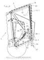
- a machine 1 for receiving and pressing agricultural Crop has a bale forming device 2, which forms a winding chamber 3.
- the Winding chamber 3 has an inlet opening 4, through which generally with a receiving device 6 recorded crop such as hay or Anwelkgut in the winding chamber 3 can be transported.
- a drive roller 7 divides the bale forming device 2 into a Lasttrum 8 and a Leertrum 9, with Lasttrum 8 and Leertrum 9 by the on the Distinguish acting driving momentum forming crop bales.
- rollers 11 additionally limit the winding chamber 3.
- the load strand 8 of the bale forming device 2 in addition to a Starting chamber forming guide devices 12 at.
- the guide devices 12 formed as pulleys, but it can hereby for example, to act on one or more guide surfaces.
- the bale forming device 2 is under with the aid of an energy storage device 13 of the memory 14 Held tension.
- an energy storage device 13 of the memory 14 Held tension.
- the memory 14 essentially has a clamping arm 19 provided with a deflection roller 18 on, which acts as a spring element force accumulator 13 attacks. Fills the winding chamber 3 with crop, so an outward pressure on the load strand 8 is exercised and the spring element 13 is compressed. This changes between the guide roller 21 and Guide roller 18 extending length of the bale forming device 2 and the Erntegutballenver mecanicrung goes along with an enlargement of the winding chamber 3. This Erntegutballenver packagedrung is called a bale forming phase.
- the memory 14 has a designated 22 actuating means, which is a limiting element 23 and an abutment 24 as a housing-fixed support comprises.
- the limiting element 23 about an axis 26, which is the axis of rotation of the deflection roller 18 corresponds, pivotable. Due to the different angles that the limiting element 23 can assume relative to the clamping arm 19, the limiting element 23rd Thus, in the different areas formed by the lugs 27 areas in contact with the Abutment 24 arrive. Accordingly, different lengths of the bale forming device 2 released and it builds a pressing pressure only at different, specifiable Bale diameters.
- the adjusting means 22 has in the embodiment described in Figure 3 in addition to a Actuator 28 with recesses 29 which, for a locking of the limiting element 23 in the described different angular positions with respect to the clamping arm 19 concern wear.
- an unspecified numbered attachment engages the limiting element 23rd is attached, releasably in the recesses 29 and thus locks the limiting element 23 in different positions.
- the measuring device 30 comprises in this embodiment a lever arm 31, one on the Housing arranged spring element 33 and designated as connections 34 signal transmission elements.
- the limiting element 23 enters Appendix with a lever arm 31 of the abutment 24.
- This lever arm 31 is by means of a Rotary axis 32 is partially rotatably mounted and at its the contact point of the limiting element 23 opposite end hung on a fixed spring 33 fixed to the housing.
- the fixed to the housing spring 33 takes away from the lever arm 31 and the limiting element 23 transmitted force in the form of the adjacent, acting on the lever arm 31 Torque on and directs this with a certain small deflection in turn in the Housing of the machine continues.
- the deflection of the spring is proportional to that of the limiting element 23 transmitted force.
- a signal transmission element 34 is so the deflection corresponding to the pressing pressure or the tension of the bale forming device 2 the spring 33 on a display device for the operating personnel of the machine 1 according to the invention transfer. As can be seen, this is therefore a mechanical measuring device 30.
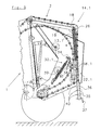
- FIGs 4 and 5 another embodiment of a machine for recording and Pressing of agricultural crop closer illustrates where a measuring device 30.1 is already activatable during the bale forming phase in order to determine bale characteristics, so that thereby the filling of the winding chamber or the formation of the round bale during the Bale forming phase up to the specified bale size, especially with small crop swaths is improved.
- the Bale forming device 2 by means of an energy storage 13.1 of the memory 14.1 under tension held.
- the energy storage 13.1 is here directly in the region of the guide roller 18 to the clamping arm 19 hinged.
- an adjusting means 22.1 is associated with the accumulator, which consists of a push rod 35 which is within the turns of the as a compression spring trained force accumulator 13.1 extends and continues in a tubular element 36.
- a pivot lever 38 of the measuring device 30.1 which is pivotally mounted on the housing of the machine 1, provides over a first lever arm 38.1 for the support of the tubular element 36, while at the end of a second lever arm 38.2 a tension spring 39 attacks, the tensile force is adjustable.
- the power relations at this measuring device 30.1 are inventively designed so that already during the bale forming phase, a deflection of the lever arm 38.2 of the pivot lever 38 from its initial position takes place, which takes this in an empty winding chamber.
- the measured variable, which is determined in the bale forming phase of the measuring device 30.1 corresponds to one Bale characteristic corresponding to the bale diameter.
- the time when an activation the measuring device 30.1 is done by varying the force ratio of the spring forces of Springs 13.1 and 39 or the length ratios of the lever arms 38.1 and 38.2 influenced become.
- the part of Adjusting means 22, 22.1 which, upon reaching a predetermined diameter of the Erntegutballens the further release of bale forming device 2 limited, not mechanical but For example, has electro-mechanical elements. This could, for example, to DMS elements acting on the limiting element 23 (Fig. 3) or on the push rod 35 (Fig. 4.5) can receive a pressure.
- measuring device 30, 30.1 mechanical or electro-mechanical components can have at least one connection of the measuring device 30, 30.1 with a Display unit a mechanical or an electrical.
- a mechanical or an electrical For the latter, the mechanical Signal converted into an electrical, which then to a display unit for the operating personnel can be forwarded.
- An essential advantage of the illustrated measuring device 30, 30.1 lies in the simplicity of their construction and thus in their cost-effective Production.
Landscapes
- Life Sciences & Earth Sciences (AREA)
- Environmental Sciences (AREA)
- Storage Of Harvested Produce (AREA)
- Soil Working Implements (AREA)
- Harvesting Machines For Specific Crops (AREA)
- Threshing Machine Elements (AREA)
- Sowing (AREA)
Abstract
Description
Die Erfindung betrifft eine Maschine zum Aufnehmen und Pressen von landwirtschaftlichem Erntegut mit einer von zumindest einer Ballenformeinrichtung gebildeten Wickelkammer zur Erzeugung eines rollenförmigen Ballens, wobei die Ballenformeinrichtung über zumindest eine ortsfeste Antriebsrolle geführt ist und während einer Ballenformphase eine Wickelkammer ausbildet, welche sich von einer, ein geringes Volumen an Erntegut aufnehmenden Größe in eine ein größeres Volumen aufnehmende Größe ausdehnen kann, und die mindestens eine Messvorrichtung aufweist.The invention relates to a machine for picking up and pressing agricultural Crop with a winding chamber formed by at least one bale forming device for Production of a roll-shaped bale, wherein the bale forming device via at least one stationary drive roller is guided and during a bale forming phase, a winding chamber which forms from a, a small volume of crop receiving size in one can expand a larger volume receiving size, and the at least one measuring device having.
Bekannt sind Maschinen zum Aufnehmen und Pressen von landwirtschaftlichem Erntegut, die eine Messvorrichtung zur Aufnahme von insbesondere Ballenkenngrößen wie Pressdichte des Ballens oder anliegendem Pressdruck aufweisen. Die Vielzahl der von solchen Ballenkenngrößen im Laufe des Ballenformvorganges durchlaufenden Größenordnungen sind hierbei für aufwendig einzustellende und damit teure Messvorrichtungen verantwortlich.Are known machines for picking and pressing of agricultural crops, the a measuring device for recording in particular bale characteristics such as density of the Bale or adjacent pressing pressure have. The variety of such bale characteristics in the course of the Ballenformvorganges ongoing orders of magnitude are here for consuming to be set and therefore expensive measuring devices responsible.
Es ist Aufgabe der vorliegenden Erfindung, eine Maschine zum Aufnehmen und Pressen von landwirtschaftlichem Erntegut, insbesondere bezüglich ihrer Messvorrichtung zu verbessern.It is an object of the present invention to provide a machine for picking and pressing agricultural crop, in particular with respect to their measuring device to improve.
Die Aufgabe wird gelöst durch eine Maschine nach dem Oberbegriff des Anspruchs 1, bei der
nach der Ballenformphase auf den Ballen der Wickelkammer von außen nach innen eine
Verdichtungskraft ausgeübt wird und bei der der Zeitpunkt einer Aktivierung einer Messvorrichtung
zur Ermittlung von Ballenkenngrößen innerhalb eines Zeitraumes liegt, der bereits während
der Ballenformphase beginnt und sich bis zum Ende der Ballenformphase erstreckt. Somit kann
der Zeitpunkt der Aktivierung des Messvorrichtung variabel gestaltet werden, wobei etwa bei
einer Aktivierung während der Ballenformphase eine exaktere Befüllung der Wickelkammer bei
kleinen Erntegutschwaden erreichbar ist oder bei einer Aktivierung erst gegen Ende des Ballenformvorgangs
zur Bildung eines Rundballens aus großen Strohschwaden die zu verwendende
Messvorrichtung dann nur während einer kürzeren Phase verwendet wird. Entsprechend wird die
Messvorrichtung verschleißfreier arbeiten können und kann daher beispielsweise einfacher und
somit kostengünstiger hergestellt werden.The object is achieved by a machine according to the preamble of
Bei einer vorteilhaften Ausgestaltung der Erfindung ist die Messvorrichtung Teil eines Stellmittels, welches nach Abschluss der Ballenformphase die weitere Freigabe der Ballenformeinrichtung aus einem Speicher begrenzt. Bei beispielsweise dem Pressdruck als aufzunehmender Ballenkenngröße kann diese somit genau in dem Bereich abgegriffen werden, in dem die vom Gehäuse abzustützenden Kräfte direkt in dieses übertragen werden, was eine direkte und entsprechend genaue Art der Messung der aufzunehmenden Größen darstellt.In an advantageous embodiment of the invention, the measuring device is part of an actuating means, which after completion of the bale forming phase, the further release of the bale forming device limited from a store. For example, the pressing pressure as aufzunehmender Bale characteristic, this can thus be tapped exactly in the area in which the from Housing forces to be transmitted directly into this, which is a direct and correspondingly accurate type of measurement of the sizes to be recorded.
Sinnvollerweise weist eine erfindungsgemäße Maschine in Fahrtrichtung links und rechts des Zentrums des Erntegutballens Messvorrichtungen auf, um lokal unterschiedliche Ballenkenngrößen zu messen. So kann beispielsweise festgestellt werden, ob es aufgrund nicht mittiger Aufnahme eines Erntegutschwadens zu einer ungleichmäßigen Ausbildung eines dann nicht exakt zylindrischen Erntegutballens kommt.It makes sense, a machine according to the invention in the direction of travel left and right of Center of Erntegutballens measuring devices on locally different bale characteristics to eat. For example, it can be determined if it is due to non-central Picking a Erntegutschwadens to an uneven training then not one exactly cylindrical Erntegutballens comes.
Es ist weiterhin von Vorteil, wenn die Messvorrichtung Mittel zur Anzeige und/oder Speicherung und/oder Übermittlung der Ballenkenngrößen aufweist, um eine unmittelbare Überprüfung der aufgenommenen Messwerte zu ermöglichen, gleich wohl ist aber auch die Möglichkeit vorzusehen, dieses gegebenenfalls später durchzuführen. Hierfür kann es sich bei den zur Anzeige und/oder Speicherung und/oder Übermittlung verwendeten Vorrichtungen auch um zumindest eine Datenverarbeitungsanlage handeln, die die einzelnen Ballenkenngrößen, die während einer längeren Arbeitsphase der Maschine gemessen werden, zu einem späteren Zeitpunkt weiter verarbeitet. It is furthermore advantageous if the measuring device has means for displaying and / or storing and / or transmission of the bale characteristics to an immediate review the recorded readings, but also the possibility to do this later if necessary. This may be the case for the Display and / or storage and / or transmission devices used to act at least one data processing system, the individual bale characteristics, the be measured during a longer working phase of the machine, at a later time Time further processed.
Statt eine Aktivierung der erfindungsgemäßen Maschine durch das Bedienpersonal vorzusehen, liegt es ebenfalls im Rahmen der Erfindung, wenn sich die Messvorrichtung automatisch zum Abschluss der Ballenformphase bzw. unmittelbar davor selbstständig aktiviert. Das Bedienpersonal ist damit entlastet.Instead of providing activation of the machine according to the invention by the operating personnel, It is also within the scope of the invention, when the measuring device automatically for Completion of the bale phase or immediately before independently activated. The operating personnel is thus relieved.
Zur weitgehenden Vermeidung von Schlupf zwischen Ballenformeinrichtung und Antriebsrolle ist der Speicher außerdem vorzugsweise so ausgebildet, dass er gegen die Kraftbeaufschlagung der Ballenformeinrichtung durch eine Spannvorrichtung des Speichers bei gleichzeitig minimalem Pressdruck auf den sich bildenden Erntegutballen solange Teile der Ballenformeinrichtung frei gibt, bis der vorgebbare Durchmesser erreicht ist und sich aufgrund der Wirkstellung eines Stellmittels der Pressdruck um ein Vielfaches erhöht. Hierdurch wird in besonderer Weise gewährleistet, dass während der Ballenformphase die Ballenformeinrichtung zwar an dem in die Wickelkammer eingeführten Material anliegt und somit für eine sichere Rotation und damit eine gleichmäßige Ballenbildung des Erntegutballens sorgt. Bei einer Aktivierung der Messvorrichtung während dieser Ballenformphase ist die gemessene Ballenkenngröße verständlicherweise einer dem Ballendurchmesser entsprechenden Größe. Bei einer Aktivierung am Ende der Ballenformphase dagegen stellt die gemessene Ballenkenngröße ein Signal dar, welches dem Pressdruck entspricht.To largely avoid slippage between bale forming device and drive roller In addition, the accumulator is preferably designed to resist the application of force the bale forming device by a clamping device of the memory while minimizing Pressing pressure on the forming crop bales as long as parts of the bale forming device free until the predetermined diameter is reached and due to the active position of a Adjusting agent of the pressing pressure increased by a multiple. This is done in a special way ensures that during the bale forming phase, the bale forming while on the in the Winding chamber inserted material is applied and thus for a secure rotation and thus a uniform bale formation of the Erntegutballens provides. Upon activation of the measuring device During this bale forming phase, the measured bale characteristic is understandable a size corresponding to the bale diameter. When activated at the end of the Ballenformphase contrast, the measured bale characteristic is a signal that the Pressing pressure corresponds.
Weitere Vorteile und Einzelheiten der Erfindung ergeben sich aus den übrigen Unteransprüchen sowie den nachfolgend beschriebenen schematischen Darstellungen. In der Zeichnung zeigt:
- Figur 1:
- Einen Längsschnitt einer erfindungsgemäßen Maschine in einer einen minimalen Erntegutballen ausbildenden Stellung,
- Figur 2:
- Den Gegenstand nach
Figur 1 in einer einen maximalen Erntegutballen ausbildenden Stellung, - Figur 3:
- Die Messvorrichtung des Wickelbodenspeichers des Gegenstands nach
Figur 1 in einer ausgebrochenen, vergrößerten Darstellung, - Figur 4:
- Einen Längsschnitt einer weiteren Ausführungsform der erfindungsgemäßen Maschine in einer einen minimalen Erntegutballen ausbildenden Stellung,
- Figur 5:
- Den Gegenstand nach Figur 4 in einer einen maximalen Erntegutballen ausbildenden Stellung,
- FIG. 1:
- A longitudinal section of a machine according to the invention in a position forming a minimal crop bale,
- FIG. 2:
- The article according to FIG. 1 in a position forming a maximum crop bale,
- FIG. 3:
- The measuring device of the winding floor storage of the article of Figure 1 in an exploded, enlarged view,
- FIG. 4:
- A longitudinal section of a further embodiment of the machine according to the invention in a position forming a minimal crop bale,
- FIG. 5:
- The article according to FIG. 4 in a position forming a maximum crop bale,
Eine erfindungsgemäße Maschine 1 zum Aufnehmen und Pressen von landwirtschaftlichen
Erntegut weist eine Ballenformeinrichtung 2 auf, die eine Wickelkammer 3 ausbildet. Die
Wickelkammer 3 besitzt eine Einlassöffnung 4, durch die allgemein mit einer Aufnahmevorrichtung
6 aufgenommenes Erntegut wie beispielsweise Heu oder Anwelkgut in die Wickelkammer
3 befördert werden kann. Eine Antriebsrolle 7 unterteilt die Ballenformeinrichtung 2 in ein
Lasttrum 8 und ein Leertrum 9, wobei sich Lasttrum 8 und Leertrum 9 durch die auf den sich
bildenden Erntegutballen wirkenden Antriebsmomente unterscheiden. Beiderseits der Einlassöffnung
4 angeordnete Walzen 11 begrenzen zusätzlich die Wickelkammer 3. Zu Beginn eines
Ballenformvorgangs liegt das Lasttrum 8 der Ballenformeinrichtung 2 zusätzlich an eine
Startkammer ausbildenden Führungsvorrichtungen 12 an. Bei diesem Ausführungsbeispiel sind
die Führungsvorrichtungen 12 als Umlenkrollen ausgebildet, es kann sich hierbei jedoch
beispielsweise auch um eine oder mehrere Führungsflächen handeln.A
Die Ballenformeinrichtung 2 wird mit Hilfe eines Kraftspeichers 13 des Speichers 14 unter
Spannung gehalten. Dadurch liegen bei Beginn der Erntegutaufnahme die zwischen der Antriebsrolle
7 und einer Umlenkrolle 16 befindlichen Abschnitte des Lasttrums 8 der Ballenformeinrichtung
2 annähernd parallel zu den Seitenkanten 17 der die Wickelkammer 3 begrenzten
Führungsseitenwände.The
Der Speicher 14 weist im wesentlichen einen mit einer Umlenkrolle 18 versehenen Spannarm 19
auf, an den der als Federelement ausgebildete Kraftspeicher 13 angreift. Füllt sich die Wickelkammer
3 mit Erntegut, so wird ein nach außen gerichteter Druck auf das Lasttrum 8 ausgeübt
und das Federelement 13 wird gestaucht. Dabei ändert sich die zwischen Umlenkrolle 21 und
Umlenkrolle 18 verlaufende Länge der Ballenformeinrichtung 2 und die Erntegutballenvergrößerung
geht einher mit einer Vergrößerung der Wickelkammer 3. Diese Erntegutballenvergrößerung
wird als Ballenformphase bezeichnet.The
Der Speicher 14 weist ein mit 22 bezeichnetes Stellmittel auf, welches ein Begrenzungselement
23 und ein Widerlager 24 als gehäusefeste Abstützung umfasst.The
In der in Figur 1 dargestellten Wirkstellung des Begrenzungselements 23 greift dieses mit einer
Ausnehmung an seinem unteren Ende in das Widerlager 24 ein. Hierdurch wird die weitere
Freigabe der Ballenformeinrichtung 2, bzw. ihrer Länge aus dem Speicher 14 verhindert, so dass
es zur Ausbildung eines minimalen Erntegutballens kommt. Die vorher von dem Kraftspeicher
13, der hier ein Federelement ist, auf die Ballenformeinrichtung 2 ausgeübte Spannung wirkt nun
nur noch zusätzlich zur Begrenzung, da das Stellmittel 22 die weitere Kontraktion des Kraftspeichers
weitgehend verhindert.In the active position of the limiting
Aufgrund einer geringfügig geänderten Position des Begrenzungselements 23 bezüglich des
Spannarms 19, d.h. einer leichten Verschwenkung um die Drehachse 26 der Umlenkrolle 18,
befindet sich in Figur 2 das Widerlager 24 in Eingriff mit einem weiter oben befindlichen
Bereich des Begrenzungselements 23. Dadurch kann der Kraftspeicher 13 weiter kontraktieren
und der Speicher 14 gibt mehr Länge frei, so dass ein größerer Erntegutballen in der Wickelkammer
3 gebildet werden kann.Due to a slightly changed position of the limiting
In Figur 3 ist das Stellmittel 22 des Wickelbodenspeichers 14 deutlicher dargestellt. Um eine
zuverlässige Abstützung der auftretenden Kräfte am Gehäuse der Maschine 1 zu gewährleisten,
ist das Begrenzungselement 23 zumindest auf einer Seite im Bereich der Umlenkrolle 18 des
Spannarms 19 angeordnet. Dieses ist von Vorteil, da die auftretenden, an der Ballenformeinrichtung
2 anliegenden Kräfte über die Umlenkrolle 18 in den Spannarm 19 und das Begrenzungselement
23 geleitet und gemeinsam abgestützt werden.In Figure 3, the adjusting means 22 of the winding
Gleichzeitig ist das Begrenzungselement 23 um eine Achse 26, die der Drehachse der Umlenkrolle
18 entspricht, verschwenkbar. Aufgrund der unterschiedlichen Winkel, die das Begrenzungselement
23 relativ zum Spannarm 19 einnehmen kann, kann das Begrenzungselement 23
somit in den unterschiedlichen von den Nasen 27 ausgebildeten Bereichen in Anlage mit dem
Widerlager 24 gelangen. Entsprechend werden unterschiedliche Längen der Ballenformeinrichtung
2 freigegeben und es baut sich ein Pressdruck erst bei unterschiedlichen, vorgebbaren
Ballendurchmessern auf.At the same time, the
Das Stellmittel 22 weist in dem in Figur 3 beschriebenen Ausführungsbeispiel zusätzlich einen
Stellarm 28 mit Ausnehmungen 29 auf, die für eine Arretierung des Begrenzungselements 23 in
den beschriebenen unterschiedlichen Winkelpositionen bezüglich des Spannarms 19 Sorge
tragen. Hierfür greift eine nicht näher bezifferte Befestigung, die am Begrenzungselement 23
angebracht ist, lösbar in die Ausnehmungen 29 ein und arretiert somit das Begrenzungselement
23 in den verschiedenen Positionen.The adjusting means 22 has in the embodiment described in Figure 3 in addition to a
Die Messvorrichtung 30 umfasst in diesem Ausführungsbeispiel einen Hebelarm 31, ein an dem
Gehäuse angeordnetes Federelement 33 sowie als Verbindungen 34 bezeichnete Signalübertragungselemente.
Während des Endes der Ballenformphase gelangt das Begrenzungselement 23 in
Anlage mit einem Hebelarm 31 des Widerlagers 24. Dieser Hebelarm 31 ist mittels einer
Drehachse 32 teilweise drehbar gelagert und an seinem dem Anlagepunkt des Begrenzungselement
23 entgegengesetzten Ende an einer gehäusefest abgestützten Feder 33 aufgehängt. Die
gehäusefest abgestützte Feder 33 nimmt die vom Hebelarm 31 und von dem Begrenzungselement
23 übertragene Kraft in Form des anliegenden, auf den Hebelarm 31 wirkenden
Drehmoments auf und leitet diese bei einer gewissen geringen Auslenkung ihrerseits in das
Gehäuse der Maschine weiter. Die Auslenkung der Feder ist proportional zu der vom Begrenzungselement
23 übertragenen Kraft. Mit Hilfe eines Signalübertragungselementes 34 wird so
die dem Pressdruck bzw. der Spannung der Ballenformeinrichtung 2 entsprechende Auslenkung
der Feder 33 auf ein Anzeigegerät für das Bedienpersonal der erfindungsgemäßen Maschine 1
übertragen. Ersichtlich handelt es sich hierbei also um eine mechanische Messvorrichtung 30.The measuring
In den Figuren 4 und 5 wird eine weitere Ausführungsform einer Maschine zum Aufnehmen und
Pressen von landwirtschaftlichem Erntegut näher veranschaulicht, bei der eine Messvorrichtung
30.1 zur Ermittlung von Ballenkenngrößen bereits während der Ballenformphase aktivierbar ist,
so dass damit die Befüllung der Wickelkammer bzw. die Bildung des Rundballens während der
Ballenformphase bis zur vorgegebenen Ballengröße insbesondere bei kleinen Erntegutschwaden
verbessert ist. Wie aus den Figuren 4 und 5 hervorgeht, wird bei dieser Ausführungsform die
Ballenformeinrichtung 2 mit Hilfe eines Kraftspeichers 13.1 des Speichers 14.1 unter Spannung
gehalten. Der Kraftspeicher 13.1 ist hier direkt im Bereich der Umlenkrolle 18 an den Spannarm
19 angelenkt. Zur Vorgabe des gewünschten Ballendurchmessers während der Ballenformphase
und zur Führung des Kraftspeichers 13.1 ist dem Speicher ein Stellmittel 22.1 zugeordnet,
welches aus einer Druckstange 35 besteht, die sich innerhalb der Windungen des als Druckfeder
ausgebildeten Kraftspeichers 13.1 erstreckt und sich in einem Rohrelement 36 fortsetzt. Die
Auswahl der jeweiligen Ballendurchmesser erfolgt über einen Steckbolzen 37, der in eine von
mehreren Querbohrungen 40 des Rohrelementes einsetzbar ist und somit ein weiteres Einschieben
der Druckstange 35 in das Rohrelement 36 verhindert. Ein Schwenkhebel 38 der Messvorrichtung
30.1, der schwenkbeweglich am Gehäuse der Maschine 1 angebracht ist, sorgt über
einen ersten Hebelarm 38.1 für die Halterung des Rohrelementes 36, während am Ende eines
zweiten Hebelarmes 38.2 eine Zugfeder 39 angreift, deren Zugkraft verstellbar ist. Die Kraftverhältnisse
an dieser Messvorrichtung 30.1 sind erfindungsgemäß so gestaltet, dass bereits
während der Ballenformphase eine Auslenkung des Hebelarms 38.2 des Schwenkhebels 38 aus
seiner Ausgangslage erfolgt, welche dieser bei leerer Wickelkammer einnimmt. Die Messgröße,
die in der Ballenformphase von der Messvorrichtung 30.1 ermittelt wird, entspricht einer
Ballenkenngröße, die dem Ballendurchmesser entspricht. Der Zeitpunkt, wann eine Aktivierung
der Messvorrichtung 30.1 erfolgt, kann durch Variierung der Kräfteverhältnis der Federkräfte der
Federn 13.1 und 39 bzw. der Längenverhältnisse der Hebelarme 38.1 und 38.2 beeinflusst
werden.In Figures 4 and 5, another embodiment of a machine for recording and
Pressing of agricultural crop closer illustrates where a measuring device
30.1 is already activatable during the bale forming phase in order to determine bale characteristics,
so that thereby the filling of the winding chamber or the formation of the round bale during the
Bale forming phase up to the specified bale size, especially with small crop swaths
is improved. As is apparent from Figures 4 and 5, in this embodiment, the
Auch hier ist wiederum vorgesehen, die gewonnenen Ballenkenngrößen durch Signalübertragungselemente
34 an geeignete Ausgabe- oder Anzeigegeräte weiterzuleiten.Again, it is provided, the obtained bale characteristics by
Statt der Auslenkung einer Feder 33 und 39 der Messvorrichtungen 30, 30.1 können im Rahmen
der Erfindung auch andere, eine Längenveränderung aufweisende und/oder komprimierbare
Elemente verwendet werden, beispielsweise Gaszylinder.Instead of the deflection of a
Es liegt auch im Rahmen der Erfindung, wenn die Messvorrichtung 30, 30.1 , die Teil des
Stellmittels 22, 22.1 ist, welches bei Erreichen eines vorgegebenen Durchmessers des Erntegutballens
die weitere Freigabe von Ballenformeinrichtung 2 begrenzt, nicht mechanische sondern
beispielsweise elektro-mechanische Elemente aufweist. Hierbei könnte es sich beispielsweise um
DMS-Elemente handeln, die an dem Begrenzungselement 23 (Fig. 3) oder an der Druckstange
35 (Fig. 4,5) einen Druck aufnehmen können.It is also within the scope of the invention, when the measuring
Ebenso, wie die Messvorrichtung 30, 30.1 mechanische oder elektro-mechanische Komponenten
aufweisen kann, ist die zumindest eine Verbindung der Messvorrichtung 30, 30.1 mit einer
Anzeigeeinheit eine mechanische oder auch eine elektrische. Für letztere wird das mechanische
Signal in ein elektrisches umgewandelt, welches dann zu einer Anzeigeeinheit für das Bedienpersonal
weitergeleitet werden kann. Ein wesentlicher Vorteil der dargestellten Messvorrichtung
30, 30.1 liegt hierbei in der Einfachheit ihrer Konstruktion und somit in ihrer kostengünstigen
Herstellung.Likewise, like the measuring
Claims (14)
Priority Applications (1)
| Application Number | Priority Date | Filing Date | Title |
|---|---|---|---|
| PL05009891T PL1595442T3 (en) | 2004-05-11 | 2005-05-06 | Device for picking up and pressing of harvested agricultural crop |
Applications Claiming Priority (2)
| Application Number | Priority Date | Filing Date | Title |
|---|---|---|---|
| DE102004023702A DE102004023702B4 (en) | 2004-05-11 | 2004-05-11 | Machine for picking up and pressing agricultural crops |
| DE102004023702 | 2004-05-11 |
Publications (2)
| Publication Number | Publication Date |
|---|---|
| EP1595442A1 true EP1595442A1 (en) | 2005-11-16 |
| EP1595442B1 EP1595442B1 (en) | 2008-10-29 |
Family
ID=34975137
Family Applications (1)
| Application Number | Title | Priority Date | Filing Date |
|---|---|---|---|
| EP05009891A Active EP1595442B1 (en) | 2004-05-11 | 2005-05-06 | Device for picking up and pressing of harvested agricultural crop |
Country Status (4)
| Country | Link |
|---|---|
| EP (1) | EP1595442B1 (en) |
| AT (1) | ATE412336T1 (en) |
| DE (2) | DE102004023702B4 (en) |
| PL (1) | PL1595442T3 (en) |
Citations (4)
| Publication number | Priority date | Publication date | Assignee | Title |
|---|---|---|---|---|
| US4224867A (en) * | 1979-03-21 | 1980-09-30 | Hesston Corporation | Crop loading monitor for rotary balers |
| US4246743A (en) * | 1979-08-01 | 1981-01-27 | Sperry Corporation | Full bale alarm system |
| FR2647630A1 (en) * | 1989-06-06 | 1990-12-07 | Claas Ohg | Baling press for round bales for products of agricultural harvest |
| US5226359A (en) * | 1992-03-10 | 1993-07-13 | Vermeer Manufacturing Company | Bale size indicator |
Family Cites Families (4)
| Publication number | Priority date | Publication date | Assignee | Title |
|---|---|---|---|---|
| US4257219A (en) * | 1979-08-27 | 1981-03-24 | Gehl Company | Cylindrical bale forming machine having hydraulic control means for controlling the bale density |
| IT1277868B1 (en) * | 1995-07-24 | 1997-11-12 | Antonio Feraboli | ROUND BALER FOR COLLECTING AND FORMING CYLINDRICAL BALES OF FORAGE OR STRAW, OF THE VARIABLE CHAMBER TYPE, WITH CHAMBER |
| DE29814775U1 (en) * | 1998-08-18 | 1998-11-12 | Claas Usines France | Round baler |
| DE20005963U1 (en) * | 2000-03-31 | 2000-06-21 | Kverneland Gottmadingen Gmbh & | Agricultural machine |
-
2004
- 2004-05-11 DE DE102004023702A patent/DE102004023702B4/en not_active Expired - Fee Related
-
2005
- 2005-05-06 PL PL05009891T patent/PL1595442T3/en unknown
- 2005-05-06 AT AT05009891T patent/ATE412336T1/en active
- 2005-05-06 EP EP05009891A patent/EP1595442B1/en active Active
- 2005-05-06 DE DE502005005777T patent/DE502005005777D1/en active Active
Patent Citations (4)
| Publication number | Priority date | Publication date | Assignee | Title |
|---|---|---|---|---|
| US4224867A (en) * | 1979-03-21 | 1980-09-30 | Hesston Corporation | Crop loading monitor for rotary balers |
| US4246743A (en) * | 1979-08-01 | 1981-01-27 | Sperry Corporation | Full bale alarm system |
| FR2647630A1 (en) * | 1989-06-06 | 1990-12-07 | Claas Ohg | Baling press for round bales for products of agricultural harvest |
| US5226359A (en) * | 1992-03-10 | 1993-07-13 | Vermeer Manufacturing Company | Bale size indicator |
Also Published As
| Publication number | Publication date |
|---|---|
| DE102004023702A1 (en) | 2005-12-15 |
| ATE412336T1 (en) | 2008-11-15 |
| EP1595442B1 (en) | 2008-10-29 |
| DE502005005777D1 (en) | 2008-12-11 |
| DE102004023702B4 (en) | 2007-03-08 |
| PL1595442T3 (en) | 2009-04-30 |
Similar Documents
| Publication | Publication Date | Title |
|---|---|---|
| DE3414080C2 (en) | ||
| EP1595438A1 (en) | Device for picking up and pressing of harvested agricultural crop | |
| EP1595443B1 (en) | Device for picking up and pressing of harvested agricultural crop | |
| EP2198687B1 (en) | Knot device for a large agricultural baler | |
| EP3391728B1 (en) | Baling press | |
| DE602006000923T2 (en) | Yarn clamping device for a baling press | |
| DE60016841T2 (en) | Sensor arrangement for an agricultural baler | |
| DE102004019286A1 (en) | baler | |
| DE2735410A1 (en) | COMPRESSION MACHINE, IN PARTICULAR BALING PRESS, FOR COMPRESSING VARIOUS MATERIALS | |
| DE19913030A1 (en) | Baling press for producing square bales of, e.g. straw has press shoe mounted on connecting rods which link it to crank pin by joints which can be disconnected while crank revolves, press shoe being locked at its dead point during this time | |
| EP3028561B1 (en) | Fixed chamber press | |
| DE102020002578A1 (en) | Binding device for an agricultural crop press and agricultural crop press with such a binding device | |
| EP1595442B1 (en) | Device for picking up and pressing of harvested agricultural crop | |
| EP1401710B1 (en) | Knotter hook and cord knotter equipped with the same | |
| DE102016117755B4 (en) | Method of controlling bale length and baler using this method | |
| EP1745691B1 (en) | Twine knotter, in particular for baler | |
| DE102017010639A1 (en) | Press and method for producing rectangular bales | |
| DE2640563A1 (en) | BINDING DEVICE ON ROUND BALERS | |
| DE3019949C2 (en) | ||
| EP1595441B1 (en) | Device for picking up and pressing of harvested crop | |
| EP0998845A1 (en) | Device for actuating a clutch for the tying device of a large bale press | |
| DE102018112844A1 (en) | Baler and method of operating a baler | |
| EP1595440B1 (en) | Device for picking up and pressing of harvested agricultural crop | |
| DE102004023703B4 (en) | Machine for picking up and pressing agricultural crops | |
| DE102022111818A1 (en) | Method for operating a round baler and round baler |
Legal Events
| Date | Code | Title | Description |
|---|---|---|---|
| PUAI | Public reference made under article 153(3) epc to a published international application that has entered the european phase |
Free format text: ORIGINAL CODE: 0009012 |
|
| AK | Designated contracting states |
Kind code of ref document: A1 Designated state(s): AT BE BG CH CY CZ DE DK EE ES FI FR GB GR HU IE IS IT LI LT LU MC NL PL PT RO SE SI SK TR |
|
| AX | Request for extension of the european patent |
Extension state: AL BA HR LV MK YU |
|
| 17P | Request for examination filed |
Effective date: 20060515 |
|
| AKX | Designation fees paid |
Designated state(s): AT BE BG CH CY CZ DE DK EE ES FI FR GB GR HU IE IS IT LI LT LU MC NL PL PT RO SE SI SK TR |
|
| 17Q | First examination report despatched |
Effective date: 20070228 |
|
| GRAP | Despatch of communication of intention to grant a patent |
Free format text: ORIGINAL CODE: EPIDOSNIGR1 |
|
| GRAS | Grant fee paid |
Free format text: ORIGINAL CODE: EPIDOSNIGR3 |
|
| GRAA | (expected) grant |
Free format text: ORIGINAL CODE: 0009210 |
|
| AK | Designated contracting states |
Kind code of ref document: B1 Designated state(s): AT BE BG CH CY CZ DE DK EE ES FI FR GB GR HU IE IS IT LI LT LU MC NL PL PT RO SE SI SK TR |
|
| REG | Reference to a national code |
Ref country code: GB Ref legal event code: FG4D Free format text: NOT ENGLISH |
|
| REG | Reference to a national code |
Ref country code: CH Ref legal event code: EP |
|
| REG | Reference to a national code |
Ref country code: IE Ref legal event code: FG4D Free format text: LANGUAGE OF EP DOCUMENT: GERMAN |
|
| REF | Corresponds to: |
Ref document number: 502005005777 Country of ref document: DE Date of ref document: 20081211 Kind code of ref document: P |
|
| LTIE | Lt: invalidation of european patent or patent extension |
Effective date: 20081029 |
|
| PG25 | Lapsed in a contracting state [announced via postgrant information from national office to epo] |
Ref country code: LT Free format text: LAPSE BECAUSE OF FAILURE TO SUBMIT A TRANSLATION OF THE DESCRIPTION OR TO PAY THE FEE WITHIN THE PRESCRIBED TIME-LIMIT Effective date: 20081029 Ref country code: ES Free format text: LAPSE BECAUSE OF FAILURE TO SUBMIT A TRANSLATION OF THE DESCRIPTION OR TO PAY THE FEE WITHIN THE PRESCRIBED TIME-LIMIT Effective date: 20090209 Ref country code: BG Free format text: LAPSE BECAUSE OF FAILURE TO SUBMIT A TRANSLATION OF THE DESCRIPTION OR TO PAY THE FEE WITHIN THE PRESCRIBED TIME-LIMIT Effective date: 20090129 |
|
| REG | Reference to a national code |
Ref country code: PL Ref legal event code: T3 |
|
| PG25 | Lapsed in a contracting state [announced via postgrant information from national office to epo] |
Ref country code: IS Free format text: LAPSE BECAUSE OF FAILURE TO SUBMIT A TRANSLATION OF THE DESCRIPTION OR TO PAY THE FEE WITHIN THE PRESCRIBED TIME-LIMIT Effective date: 20090228 Ref country code: SI Free format text: LAPSE BECAUSE OF FAILURE TO SUBMIT A TRANSLATION OF THE DESCRIPTION OR TO PAY THE FEE WITHIN THE PRESCRIBED TIME-LIMIT Effective date: 20081029 Ref country code: PT Free format text: LAPSE BECAUSE OF FAILURE TO SUBMIT A TRANSLATION OF THE DESCRIPTION OR TO PAY THE FEE WITHIN THE PRESCRIBED TIME-LIMIT Effective date: 20090330 |
|
| PG25 | Lapsed in a contracting state [announced via postgrant information from national office to epo] |
Ref country code: DK Free format text: LAPSE BECAUSE OF FAILURE TO SUBMIT A TRANSLATION OF THE DESCRIPTION OR TO PAY THE FEE WITHIN THE PRESCRIBED TIME-LIMIT Effective date: 20081029 Ref country code: EE Free format text: LAPSE BECAUSE OF FAILURE TO SUBMIT A TRANSLATION OF THE DESCRIPTION OR TO PAY THE FEE WITHIN THE PRESCRIBED TIME-LIMIT Effective date: 20081029 Ref country code: RO Free format text: LAPSE BECAUSE OF FAILURE TO SUBMIT A TRANSLATION OF THE DESCRIPTION OR TO PAY THE FEE WITHIN THE PRESCRIBED TIME-LIMIT Effective date: 20081029 |
|
| PG25 | Lapsed in a contracting state [announced via postgrant information from national office to epo] |
Ref country code: CZ Free format text: LAPSE BECAUSE OF FAILURE TO SUBMIT A TRANSLATION OF THE DESCRIPTION OR TO PAY THE FEE WITHIN THE PRESCRIBED TIME-LIMIT Effective date: 20081029 Ref country code: SE Free format text: LAPSE BECAUSE OF FAILURE TO SUBMIT A TRANSLATION OF THE DESCRIPTION OR TO PAY THE FEE WITHIN THE PRESCRIBED TIME-LIMIT Effective date: 20090129 |
|
| PLBE | No opposition filed within time limit |
Free format text: ORIGINAL CODE: 0009261 |
|
| STAA | Information on the status of an ep patent application or granted ep patent |
Free format text: STATUS: NO OPPOSITION FILED WITHIN TIME LIMIT |
|
| PG25 | Lapsed in a contracting state [announced via postgrant information from national office to epo] |
Ref country code: SK Free format text: LAPSE BECAUSE OF FAILURE TO SUBMIT A TRANSLATION OF THE DESCRIPTION OR TO PAY THE FEE WITHIN THE PRESCRIBED TIME-LIMIT Effective date: 20081029 |
|
| 26N | No opposition filed |
Effective date: 20090730 |
|
| PG25 | Lapsed in a contracting state [announced via postgrant information from national office to epo] |
Ref country code: MC Free format text: LAPSE BECAUSE OF NON-PAYMENT OF DUE FEES Effective date: 20090531 |
|
| REG | Reference to a national code |
Ref country code: CH Ref legal event code: PL |
|
| GBPC | Gb: european patent ceased through non-payment of renewal fee |
Effective date: 20090506 |
|
| PG25 | Lapsed in a contracting state [announced via postgrant information from national office to epo] |
Ref country code: LI Free format text: LAPSE BECAUSE OF NON-PAYMENT OF DUE FEES Effective date: 20090531 Ref country code: CH Free format text: LAPSE BECAUSE OF NON-PAYMENT OF DUE FEES Effective date: 20090531 |
|
| PG25 | Lapsed in a contracting state [announced via postgrant information from national office to epo] |
Ref country code: GB Free format text: LAPSE BECAUSE OF NON-PAYMENT OF DUE FEES Effective date: 20090506 |
|
| PG25 | Lapsed in a contracting state [announced via postgrant information from national office to epo] |
Ref country code: GR Free format text: LAPSE BECAUSE OF FAILURE TO SUBMIT A TRANSLATION OF THE DESCRIPTION OR TO PAY THE FEE WITHIN THE PRESCRIBED TIME-LIMIT Effective date: 20090130 |
|
| PG25 | Lapsed in a contracting state [announced via postgrant information from national office to epo] |
Ref country code: LU Free format text: LAPSE BECAUSE OF NON-PAYMENT OF DUE FEES Effective date: 20090506 |
|
| PG25 | Lapsed in a contracting state [announced via postgrant information from national office to epo] |
Ref country code: HU Free format text: LAPSE BECAUSE OF FAILURE TO SUBMIT A TRANSLATION OF THE DESCRIPTION OR TO PAY THE FEE WITHIN THE PRESCRIBED TIME-LIMIT Effective date: 20090430 |
|
| PG25 | Lapsed in a contracting state [announced via postgrant information from national office to epo] |
Ref country code: TR Free format text: LAPSE BECAUSE OF FAILURE TO SUBMIT A TRANSLATION OF THE DESCRIPTION OR TO PAY THE FEE WITHIN THE PRESCRIBED TIME-LIMIT Effective date: 20081029 |
|
| PG25 | Lapsed in a contracting state [announced via postgrant information from national office to epo] |
Ref country code: CY Free format text: LAPSE BECAUSE OF FAILURE TO SUBMIT A TRANSLATION OF THE DESCRIPTION OR TO PAY THE FEE WITHIN THE PRESCRIBED TIME-LIMIT Effective date: 20081029 |
|
| REG | Reference to a national code |
Ref country code: FR Ref legal event code: PLFP Year of fee payment: 12 |
|
| REG | Reference to a national code |
Ref country code: FR Ref legal event code: PLFP Year of fee payment: 13 |
|
| REG | Reference to a national code |
Ref country code: FR Ref legal event code: PLFP Year of fee payment: 14 |
|
| REG | Reference to a national code |
Ref country code: BE Ref legal event code: HC Owner name: MASCHINENFABRIK BERNARD KRONE GMBH & CO. KG; DE Free format text: DETAILS ASSIGNMENT: CHANGE OF OWNER(S), CHANGE OF OWNER(S) NAME Effective date: 20210209 |
|
| PGFP | Annual fee paid to national office [announced via postgrant information from national office to epo] |
Ref country code: NL Payment date: 20210519 Year of fee payment: 17 Ref country code: IT Payment date: 20210531 Year of fee payment: 17 Ref country code: FR Payment date: 20210525 Year of fee payment: 17 Ref country code: FI Payment date: 20210518 Year of fee payment: 17 |
|
| PGFP | Annual fee paid to national office [announced via postgrant information from national office to epo] |
Ref country code: IE Payment date: 20210519 Year of fee payment: 17 Ref country code: PL Payment date: 20210429 Year of fee payment: 17 Ref country code: BE Payment date: 20210519 Year of fee payment: 17 Ref country code: AT Payment date: 20210518 Year of fee payment: 17 |
|
| REG | Reference to a national code |
Ref country code: DE Ref legal event code: R081 Ref document number: 502005005777 Country of ref document: DE Owner name: KRONE AGRICULTURE SE, DE Free format text: FORMER OWNER: MASCHINENFABRIK BERNARD KRONE GMBH, 48480 SPELLE, DE |
|
| REG | Reference to a national code |
Ref country code: FI Ref legal event code: PCE Owner name: KRONE AGRICULTURE SE |
|
| REG | Reference to a national code |
Ref country code: AT Ref legal event code: PC Ref document number: 412336 Country of ref document: AT Kind code of ref document: T Owner name: KRONE AGRICULTURE SE, DE Effective date: 20211022 |
|
| REG | Reference to a national code |
Ref country code: NL Ref legal event code: PD Owner name: KRONE AGRICULTURE SE; DE Free format text: DETAILS ASSIGNMENT: CHANGE OF OWNER(S), MERGE; FORMER OWNER NAME: MASCHINENFABRIK KRONE BETEILIGUNGS-GMBH Effective date: 20211126 Ref country code: NL Ref legal event code: HC Owner name: MASCHINENFABRIK KRONE BETEILIGUNGS-GMBH; DE Free format text: DETAILS ASSIGNMENT: CHANGE OF OWNER(S), CHANGE OF OWNER(S) NAME; FORMER OWNER NAME: MASCHINENFABRIK BERNARD KRONE GMBH Effective date: 20211126 |
|
| REG | Reference to a national code |
Ref country code: DE Ref legal event code: R084 Ref document number: 502005005777 Country of ref document: DE |
|
| REG | Reference to a national code |
Ref country code: NL Ref legal event code: MM Effective date: 20220601 |
|
| REG | Reference to a national code |
Ref country code: AT Ref legal event code: MM01 Ref document number: 412336 Country of ref document: AT Kind code of ref document: T Effective date: 20220506 |
|
| REG | Reference to a national code |
Ref country code: BE Ref legal event code: MM Effective date: 20220531 |
|
| PG25 | Lapsed in a contracting state [announced via postgrant information from national office to epo] |
Ref country code: FI Free format text: LAPSE BECAUSE OF NON-PAYMENT OF DUE FEES Effective date: 20220506 Ref country code: AT Free format text: LAPSE BECAUSE OF NON-PAYMENT OF DUE FEES Effective date: 20220506 |
|
| PG25 | Lapsed in a contracting state [announced via postgrant information from national office to epo] |
Ref country code: IE Free format text: LAPSE BECAUSE OF NON-PAYMENT OF DUE FEES Effective date: 20220506 Ref country code: FR Free format text: LAPSE BECAUSE OF NON-PAYMENT OF DUE FEES Effective date: 20220531 |
|
| PG25 | Lapsed in a contracting state [announced via postgrant information from national office to epo] |
Ref country code: BE Free format text: LAPSE BECAUSE OF NON-PAYMENT OF DUE FEES Effective date: 20220531 |
|
| P01 | Opt-out of the competence of the unified patent court (upc) registered |
Effective date: 20230517 |
|
| PG25 | Lapsed in a contracting state [announced via postgrant information from national office to epo] |
Ref country code: NL Free format text: LAPSE BECAUSE OF NON-PAYMENT OF DUE FEES Effective date: 20220601 |
|
| PG25 | Lapsed in a contracting state [announced via postgrant information from national office to epo] |
Ref country code: IT Free format text: LAPSE BECAUSE OF NON-PAYMENT OF DUE FEES Effective date: 20220506 |
|
| PGFP | Annual fee paid to national office [announced via postgrant information from national office to epo] |
Ref country code: DE Payment date: 20230519 Year of fee payment: 19 |
|
| PG25 | Lapsed in a contracting state [announced via postgrant information from national office to epo] |
Ref country code: PL Free format text: LAPSE BECAUSE OF NON-PAYMENT OF DUE FEES Effective date: 20220506 |