EP1597955B1 - Internal combustion engine traction drive with electric cutting unit drive for walk-behind greens mower - Google Patents
Internal combustion engine traction drive with electric cutting unit drive for walk-behind greens mower Download PDFInfo
- Publication number
- EP1597955B1 EP1597955B1 EP05250080A EP05250080A EP1597955B1 EP 1597955 B1 EP1597955 B1 EP 1597955B1 EP 05250080 A EP05250080 A EP 05250080A EP 05250080 A EP05250080 A EP 05250080A EP 1597955 B1 EP1597955 B1 EP 1597955B1
- Authority
- EP
- European Patent Office
- Prior art keywords
- mobile structure
- electric motor
- internal combustion
- combustion engine
- greens mower
- Prior art date
- Legal status (The legal status is an assumption and is not a legal conclusion. Google has not performed a legal analysis and makes no representation as to the accuracy of the status listed.)
- Active
Links
- 235000021384 green leafy vegetables Nutrition 0.000 title claims abstract description 51
- 238000002485 combustion reaction Methods 0.000 title claims abstract description 26
- 244000025254 Cannabis sativa Species 0.000 claims abstract description 18
- 230000004044 response Effects 0.000 claims description 4
- 230000005611 electricity Effects 0.000 claims 3
- 230000005540 biological transmission Effects 0.000 description 5
- 230000007246 mechanism Effects 0.000 description 4
- 238000010276 construction Methods 0.000 description 2
- 238000012546 transfer Methods 0.000 description 2
- 241001494496 Leersia Species 0.000 description 1
- 238000004891 communication Methods 0.000 description 1
- 238000013461 design Methods 0.000 description 1
- 230000007613 environmental effect Effects 0.000 description 1
- 230000036541 health Effects 0.000 description 1
- 230000002706 hydrostatic effect Effects 0.000 description 1
- 238000012423 maintenance Methods 0.000 description 1
- 238000012544 monitoring process Methods 0.000 description 1
- 238000012545 processing Methods 0.000 description 1
- 239000007858 starting material Substances 0.000 description 1
- 238000012876 topography Methods 0.000 description 1
Images
Classifications
-
- A—HUMAN NECESSITIES
- A01—AGRICULTURE; FORESTRY; ANIMAL HUSBANDRY; HUNTING; TRAPPING; FISHING
- A01D—HARVESTING; MOWING
- A01D34/00—Mowers; Mowing apparatus of harvesters
- A01D34/01—Mowers; Mowing apparatus of harvesters characterised by features relating to the type of cutting apparatus
- A01D34/412—Mowers; Mowing apparatus of harvesters characterised by features relating to the type of cutting apparatus having rotating cutters
- A01D34/42—Mowers; Mowing apparatus of harvesters characterised by features relating to the type of cutting apparatus having rotating cutters having cutters rotating about a horizontal axis, e.g. cutting-cylinders
- A01D34/46—Mowers; Mowing apparatus of harvesters characterised by features relating to the type of cutting apparatus having rotating cutters having cutters rotating about a horizontal axis, e.g. cutting-cylinders hand-guided by a walking operator
- A01D34/47—Mowers; Mowing apparatus of harvesters characterised by features relating to the type of cutting apparatus having rotating cutters having cutters rotating about a horizontal axis, e.g. cutting-cylinders hand-guided by a walking operator with motor driven cutters or wheels
-
- A—HUMAN NECESSITIES
- A01—AGRICULTURE; FORESTRY; ANIMAL HUSBANDRY; HUNTING; TRAPPING; FISHING
- A01D—HARVESTING; MOWING
- A01D34/00—Mowers; Mowing apparatus of harvesters
- A01D34/01—Mowers; Mowing apparatus of harvesters characterised by features relating to the type of cutting apparatus
- A01D34/412—Mowers; Mowing apparatus of harvesters characterised by features relating to the type of cutting apparatus having rotating cutters
- A01D34/63—Mowers; Mowing apparatus of harvesters characterised by features relating to the type of cutting apparatus having rotating cutters having cutters rotating about a vertical axis
- A01D34/76—Driving mechanisms for the cutters
- A01D34/77—Driving mechanisms for the cutters actuated by advance of the machine
-
- A—HUMAN NECESSITIES
- A01—AGRICULTURE; FORESTRY; ANIMAL HUSBANDRY; HUNTING; TRAPPING; FISHING
- A01D—HARVESTING; MOWING
- A01D34/00—Mowers; Mowing apparatus of harvesters
- A01D34/01—Mowers; Mowing apparatus of harvesters characterised by features relating to the type of cutting apparatus
- A01D34/412—Mowers; Mowing apparatus of harvesters characterised by features relating to the type of cutting apparatus having rotating cutters
- A01D34/42—Mowers; Mowing apparatus of harvesters characterised by features relating to the type of cutting apparatus having rotating cutters having cutters rotating about a horizontal axis, e.g. cutting-cylinders
- A01D34/56—Driving mechanisms for the cutters
- A01D34/58—Driving mechanisms for the cutters electric
-
- A—HUMAN NECESSITIES
- A01—AGRICULTURE; FORESTRY; ANIMAL HUSBANDRY; HUNTING; TRAPPING; FISHING
- A01D—HARVESTING; MOWING
- A01D34/00—Mowers; Mowing apparatus of harvesters
- A01D34/01—Mowers; Mowing apparatus of harvesters characterised by features relating to the type of cutting apparatus
- A01D34/412—Mowers; Mowing apparatus of harvesters characterised by features relating to the type of cutting apparatus having rotating cutters
- A01D34/63—Mowers; Mowing apparatus of harvesters characterised by features relating to the type of cutting apparatus having rotating cutters having cutters rotating about a vertical axis
- A01D34/76—Driving mechanisms for the cutters
- A01D34/78—Driving mechanisms for the cutters electric
Definitions
- the present invention relates to greens mowers and, more particularly, relates to a greens mower having an internal combustion engine traction drive and an electric cutting unit drive for improved cutting performance and operation.
- greens mowers are particularly useful in mowing golf course greens, which are known to require exacting mowing results to assure that the grass is cut consistently throughout the green.
- these greens mowers are either walk-behind type mowers or riding mowers.
- Greens mowers generally employ a reel type mowing unit as opposed to a rotary type mowing unit.
- the clip rate of these reel type mowing units are of utmost concern due to the fact that the clip rate often determines the consistency and quality of the cut, which leads to improved turf health. Because of the time required to grow a mature green and the cost associated with therewith, it is extremely important that greens mowers operate properly and not damage the turf.
- clip rate is generally understood to mean the ratio between the rotational speed of the reel and the corresponding speed of the traction or drive unit.
- the clip rate can often be measured by the distance between the locations of individual sequential grass cuts produced by the rotating reel blades successively moving over the grass.
- the grass between the locations of the cuts will necessarily be left taller than the cut grass at the cut locations. Consequently, the cut rate is vital to producing an optimum condition of the grass on the golf course green.
- Such conventional greens mowers often employ complex disengagement systems that the operator is required to actuate in order to engage and disengage the mowing unit. These systems often require the operator to actuate a lever separate from the handle, which may lead to undesirable cutting performance as the mowing unit is being disengaged.
- a walk-behind greens mower having an advantageous construction.
- the greens mower includes a mobile structure and a ground engaging traction member rotatably coupled to the mobile structure.
- the ground engaging traction member imparts traction movement to the mobile structure for movement on the ground at a ground speed.
- An internal combustion engine is supported on the mobile structure and outputs a driving force to the ground engaging traction member.
- a bed knife is supported by the mobile structure having a cutting edge that cooperates with a grass cutting reel rotatably supported on the mobile structure.
- An electric motor supported on the mobile structure rotatably driving the grass cutting reel at a rotational speed that can vary depending upon the detected ground speed.
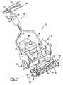
- FIG. 1 illustrates a greens mower 10 incorporating the principles of the present invention.
- Greens mower 10 is a reel-type mower having a base portion 12 and a floating or articulating mowing unit 14.
- Mowing unit 14 is articulately coupled to base portion 12 through a pivoting mechanism 16.
- Mowing unit 14 includes a rotatable greens mower reel 18 having spiraled blades 20 equally spaced around a reel shaft 22.
- Reel shaft 22 is generally elongated and defines a rotation axis 24 extending along the length of reel shaft 22.
- a conventional fixed bed knife (not shown) is operably mounted to mowing unit 14. Blades 20 orbit relative to shaft 22 and move past the fixed bed knife for the usual and well-known function of cutting the grass.
- Mowing unit 14 further includes a pair of ground engaging rollers 26 rotatably mounted along a forward and rearward portion of mowing unit 14. The pair of ground engaging rollers 26 serve to support mowing unit 14 for movement on the ground.
- the pair of ground engaging rollers 26 are preferably adjustable to define a cutting height.
- Mowing unit 14 further includes a variable electric motor 28.
- Electric motor 28 is illustrated mounted to a side member 30 of mowing unit 14. Electric motor 28 is then operably coupled to reel 18 to rotatably drive reel 18 through a transmission system (not shown).
- the transmission system may include belts, gears, chains, or the like in a conventional fashion to transfer the drive force from electric motor 28 to reel 18.
- the transmission system extending between electric motor 28 and reel 18 is simple in construction, because it is directly mounted to mowing unit 14. Therefore, any articulation of mowing unit 14 does not affect the relative positional relationship of the drive motor and the reel, as is common in prior art articulating greens mowers. Consequently, the transmission system need only include the necessary pieces to define a range of rotational speeds relative to the capacity of electric motor 28, such as a simple gear train.
- electric motor 28 is illustrated mounted to side member 30 of mowing unit 14, it should be appreciated that electric motor 28 may be mounted in any one of a plurality of locations.
- electric motor 28 may be mounted generally above reel 18, either to one side or centered, or, alternatively, electric motor 28 may be mounted within reel shaft 22 to provide additional protection of electric mower 28 from environmental damage and to provide improved weight balance of mowing unit 14.
- Base portion 12 generally includes an internal combustion engine 32, a frame 34, a lawn roller 36, a drive system 38, and a handle assembly 40.
- Internal combustion engine 32 is of conventional design and is mounted on frame 34.
- Internal combustion engine 32 may include an electric starter for improved convenience.
- Internal combustion engine 32 further includes a generator 42 outputting electrical power during engine operation. The electrical power from generator 42 is transferred to electrical motor 28 via a flexible line 44 to drive electrical motor 28 and, thus, reel 18.
- Lawn roller 36 is rotatably mounted to frame 34 through a roller axle 46. Lawn roller 36 supports base portion 12 on the ground and serves as the traction drive for greens mower 10. Other ground-supporting traction members could be substituted.
- Drive system 38 is operably coupled between an output shaft 48 and lawn roller 36.
- Drive system 38 generally includes a drive pulley (not shown) mounted to output shaft 48 for rotation therewith and an idler pulley (not shown) mounted to lawn roller 36 for rotation therewith.
- a drive belt (not shown) extends between the drive pulley and the idler pulley to transfer drive force from internal combustion engine 32 to lawn roller 36.
- Handle assembly 40 includes a handle 50 suitably connected with frame 34.
- Handle 50 includes a grip portion 52 which the operator can hold in steering greens mower 10.
- a movably mounted bail or operator hand control 54 is pivotally connected to handle 50 and is movable toward and away from the grip portion 52.
- the operation of hand control 54 may be similar to that disclosed in commonly owned U.S. Patent No. 6,523,334 . In this arrangement, the operator can hold both handle 50 and hand control 54 while guiding greens mower 10.
- traction drive system 38 is interrupted in a manner similar to that disclosed in the '334 Patent.
- handle assembly 40 further includes electrical elements 56 mounted thereon, which are therefore presented to the user for observation or actuation.
- a mower controller 58 is mounted on handle assembly 40.
- Mower controller 58 is preferably a central processing unit capable of monitoring and controlling the various functions of greens mower 10. Although mower controller 58 may be configured in any number of ways conducive to a desired operation, mower controller 58 is most preferably in communication with electric motor 28 via a wire 60. In this regard, mower controller 58 is capable of controlling a rotational speed of reel 18. This control capability can be simple to maintain a desired revolutions per minute, irrespective of drive speed of greens mower 10. However, more desirably, mower controller 58 instead is capable of varying the rotational speed of electric motor 28 and, thus, reel 18 in portion to a detected drive speed of greens mower 10. The drive speed of greens mower 10 may be detected using a sensor operably coupled to either lawn roller 38 or rollers 26.
- This sensor outputs a signal in response to a detected rotational speed of lawn roller 38 or rollers 26, which is used by mower controller 58 to determine the drive speed of greens mower 10. Accordingly, an output signal from mower controller 58 to electric motor 28 varies the rotational speed of electric motor 28, thereby varying the clip rate of reel 18.
- mower controller 58 preferably includes an operator actuatable switch 62 for conveniently turning on or off electric motor 28 to selectively drive reel 18.
- Switch 62 may be conveniently located on handle 50 such that the operator need not remove her hands from handle 50 during operation. Such a switch permits reel 18 to be turned on or off for improved safety and longevity.
- an optional battery 64 may be coupled to frame 34.
- Battery 64 may be used to aid in the starting of internal combustion engine 32, power electrical elements 56, and/or power electric motor 28, either solely or in combination with generator 42.
- the present invention provides a number of advantages over the prior art. Particularly, the present invention provides an internal combustion powered greens mowers that is capable of consistently maintaining a desired clip rate that is both reliable and easily configurable. Additionally, the present invention provides an internal combustion powered greens mowers that can operably drive an articulating mowing unit without the need for complex mechanical drive systems. Still further, the present invention provides a greens mower having a simple and safe disengagement system to permit the quick and convenient turning on and off of the mowing unit.
- a walk-behind greens mower having a mobile structure and a ground engaging traction member rotatably coupled to the mobile structure.
- the ground engaging traction member imparts traction movement to the mobile structure for movement on the ground at ground speed.
- An internal combustion engine is supported on the mobile structure and outputs a driving force to the ground engaging traction member.
- a bed knife is supported by the mobile structure having a cutting edge that cooperates with a grass cutting reel rotatably supported on the mobile structure.
- An electric motor supported on the mobile structure rotatably driving the grass cutting reel at the rotational speed that can vary depending upon the detected ground speed.
Abstract
Description
- The present invention relates to greens mowers and, more particularly, relates to a greens mower having an internal combustion engine traction drive and an electric cutting unit drive for improved cutting performance and operation.
- As is known in the prior art, greens mowers are particularly useful in mowing golf course greens, which are known to require exacting mowing results to assure that the grass is cut consistently throughout the green. Traditionally, these greens mowers are either walk-behind type mowers or riding mowers.
- Greens mowers generally employ a reel type mowing unit as opposed to a rotary type mowing unit. The clip rate of these reel type mowing units are of utmost concern due to the fact that the clip rate often determines the consistency and quality of the cut, which leads to improved turf health. Because of the time required to grow a mature green and the cost associated with therewith, it is extremely important that greens mowers operate properly and not damage the turf.
- The term clip rate is generally understood to mean the ratio between the rotational speed of the reel and the corresponding speed of the traction or drive unit. The clip rate can often be measured by the distance between the locations of individual sequential grass cuts produced by the rotating reel blades successively moving over the grass. The grass between the locations of the cuts will necessarily be left taller than the cut grass at the cut locations. Consequently, the cut rate is vital to producing an optimum condition of the grass on the golf course green.
- Golf course greens maintenance equipment traditionally has utilized internal combustion engines. A number of greens mowers are known in the art. Some are discussed in
U.S. Patent Nos. 3,429,110 , which discloses a mower according to the preamble of claim 1, and 4,024,996. Riding greens mowers with multiple or gang mowing units are the subject ofU.S. Patent Nos. 3,511,033 ,3,668,844 ,4,866,918 , and5,042,236 . The mowers discussed in these patents all rely on an internal combustion engine as the primary source of power and a complex drive mechanism of drive belts, gears, and/or chains or a hydrostatic system for supplying power to the ground engaging wheels and additionally to the reel mowing units. However, there are a number of disadvantages associated with the use of a greens mower employing an internal combustion engine to power both the drive mechanism and the mowing unit. - As will be appreciated by one skilled in the art, traditionally internal combustion powered greens mowers have a first disadvantage of preventing quick and convenient variation of the clip rate, because of the fixed mechanical relationship between the drive mechanism and the mowing unit. In other words, the fixed gear ratio defined by the drive belts, gears, and/or chains does not facilitate quick and convenient modifying of the clip rate without the changing of gear members or the use of variable transmissions. Consequently, the clip rate of a particular greens mower is often unchangeable without considerable time and effort.
- Additionally, recently there has been an increased interest in greens mowers having a floating or articulating mowing unit. These articulating mowing units have the ability to follow any undulations in the green more closely to provide improve cut quality over varying greens topography. However, it should be appreciated that the mechanical drive unit extending between the internal combustion engine and the articulating mowing unit is often complex and cumbersome due to the inherent need to continually provide drive power as the mowing unit articulates relative to the engine.
- Still further, such conventional greens mowers often employ complex disengagement systems that the operator is required to actuate in order to engage and disengage the mowing unit. These systems often require the operator to actuate a lever separate from the handle, which may lead to undesirable cutting performance as the mowing unit is being disengaged.
- Accordingly, there exists a need in the relevant art to provide an internal combustion powered greens mowers that is capable of consistently maintaining a desired clip rate that is both reliable and easily configurable. Additionally, there exists a need in the relevant art to provide an internal combustion powered greens mowers that can operably drive an articulating mowing unit without the need for complex mechanical drive systems. Furthermore, there exists a need in the relevant art to provide a greens mower having a simple and safe disengagement system to permit the quick and convenient turning on and off of the mowing unit. Lastly, there is a need in the relevant art to provide a greens mower that overcomes the disadvantages of the prior art.
- According to the principles of the present invention, a walk-behind greens mower having an advantageous construction is provided. The greens mower includes a mobile structure and a ground engaging traction member rotatably coupled to the mobile structure. The ground engaging traction member imparts traction movement to the mobile structure for movement on the ground at a ground speed. An internal combustion engine is supported on the mobile structure and outputs a driving force to the ground engaging traction member. A bed knife is supported by the mobile structure having a cutting edge that cooperates with a grass cutting reel rotatably supported on the mobile structure. An electric motor supported on the mobile structure rotatably driving the grass cutting reel at a rotational speed that can vary depending upon the detected ground speed.
- Further areas of applicability of the present invention will become apparent from the detailed description provided hereinafter. It should be understood that the detailed description and specific examples, while indicating the preferred embodiment of the invention, are intended for purposes of illustration only and are not intended to limit the scope of the invention.
- The present invention will become more fully understood from the detailed description and the accompanying drawings, wherein:
-
FIG. 1 is a perspective view illustrating a greens mower according to the principles of the present invention. - The following description of the preferred embodiment is merely exemplary in nature and is in no way intended to limit the invention, its application, or uses.
- With reference to the figure,
FIG. 1 illustrates agreens mower 10 incorporating the principles of the present invention. Greensmower 10 is a reel-type mower having abase portion 12 and a floating or articulatingmowing unit 14.Mowing unit 14 is articulately coupled tobase portion 12 through apivoting mechanism 16. -
Mowing unit 14 includes a rotatablegreens mower reel 18 having spiraledblades 20 equally spaced around a reel shaft 22. Reel shaft 22 is generally elongated and defines arotation axis 24 extending along the length of reel shaft 22. A conventional fixed bed knife (not shown) is operably mounted to mowingunit 14.Blades 20 orbit relative to shaft 22 and move past the fixed bed knife for the usual and well-known function of cutting the grass.Mowing unit 14 further includes a pair of groundengaging rollers 26 rotatably mounted along a forward and rearward portion ofmowing unit 14. The pair of groundengaging rollers 26 serve to supportmowing unit 14 for movement on the ground. The pair of groundengaging rollers 26 are preferably adjustable to define a cutting height. -
Mowing unit 14 further includes a variableelectric motor 28.Electric motor 28 is illustrated mounted to aside member 30 ofmowing unit 14.Electric motor 28 is then operably coupled toreel 18 to rotatably drivereel 18 through a transmission system (not shown). The transmission system may include belts, gears, chains, or the like in a conventional fashion to transfer the drive force fromelectric motor 28 to reel 18. As should be appreciated, however, the transmission system extending betweenelectric motor 28 andreel 18 is simple in construction, because it is directly mounted to mowingunit 14. Therefore, any articulation ofmowing unit 14 does not affect the relative positional relationship of the drive motor and the reel, as is common in prior art articulating greens mowers. Consequently, the transmission system need only include the necessary pieces to define a range of rotational speeds relative to the capacity ofelectric motor 28, such as a simple gear train. - Although
electric motor 28 is illustrated mounted toside member 30 ofmowing unit 14, it should be appreciated thatelectric motor 28 may be mounted in any one of a plurality of locations. For example,electric motor 28 may be mounted generally abovereel 18, either to one side or centered, or, alternatively,electric motor 28 may be mounted within reel shaft 22 to provide additional protection ofelectric mower 28 from environmental damage and to provide improved weight balance ofmowing unit 14. -
Base portion 12 generally includes aninternal combustion engine 32, aframe 34, alawn roller 36, adrive system 38, and ahandle assembly 40.Internal combustion engine 32 is of conventional design and is mounted onframe 34.Internal combustion engine 32 may include an electric starter for improved convenience.Internal combustion engine 32 further includes agenerator 42 outputting electrical power during engine operation. The electrical power fromgenerator 42 is transferred toelectrical motor 28 via a flexible line 44 to driveelectrical motor 28 and, thus, reel 18. -
Lawn roller 36 is rotatably mounted to frame 34 through aroller axle 46.Lawn roller 36supports base portion 12 on the ground and serves as the traction drive forgreens mower 10. Other ground-supporting traction members could be substituted.Drive system 38 is operably coupled between anoutput shaft 48 andlawn roller 36.Drive system 38 generally includes a drive pulley (not shown) mounted tooutput shaft 48 for rotation therewith and an idler pulley (not shown) mounted tolawn roller 36 for rotation therewith. A drive belt (not shown) extends between the drive pulley and the idler pulley to transfer drive force frominternal combustion engine 32 tolawn roller 36. Thus, there exists a traction drive train frominternal combustion engine 32 to the ground-engaginglawn roller 36 capable of drivinggreens mower 10 in at least a forward direction. - Handle
assembly 40 includes ahandle 50 suitably connected withframe 34.Handle 50 includes agrip portion 52 which the operator can hold in steeringgreens mower 10. A movably mounted bail oroperator hand control 54 is pivotally connected to handle 50 and is movable toward and away from thegrip portion 52. The operation ofhand control 54 may be similar to that disclosed in commonly ownedU.S. Patent No. 6,523,334 . In this arrangement, the operator can hold both handle 50 andhand control 54 while guidinggreens mower 10. Upon release ofhand control 54,traction drive system 38 is interrupted in a manner similar to that disclosed in the '334 Patent. - Additionally, the vicinity of
handle 50 further includeselectrical elements 56 mounted thereon, which are therefore presented to the user for observation or actuation. Amower controller 58 is mounted onhandle assembly 40. -
Mower controller 58 is preferably a central processing unit capable of monitoring and controlling the various functions ofgreens mower 10. Althoughmower controller 58 may be configured in any number of ways conducive to a desired operation,mower controller 58 is most preferably in communication withelectric motor 28 via awire 60. In this regard,mower controller 58 is capable of controlling a rotational speed ofreel 18. This control capability can be simple to maintain a desired revolutions per minute, irrespective of drive speed ofgreens mower 10. However, more desirably,mower controller 58 instead is capable of varying the rotational speed ofelectric motor 28 and, thus, reel 18 in portion to a detected drive speed ofgreens mower 10. The drive speed ofgreens mower 10 may be detected using a sensor operably coupled to eitherlawn roller 38 orrollers 26. This sensor outputs a signal in response to a detected rotational speed oflawn roller 38 orrollers 26, which is used bymower controller 58 to determine the drive speed ofgreens mower 10. Accordingly, an output signal frommower controller 58 toelectric motor 28 varies the rotational speed ofelectric motor 28, thereby varying the clip rate ofreel 18. - Furthermore,
mower controller 58 preferably includes an operator actuatable switch 62 for conveniently turning on or offelectric motor 28 to selectively drivereel 18. Switch 62 may be conveniently located onhandle 50 such that the operator need not remove her hands fromhandle 50 during operation. Such a switch permitsreel 18 to be turned on or off for improved safety and longevity. - Still further, an
optional battery 64 may be coupled toframe 34.Battery 64 may be used to aid in the starting ofinternal combustion engine 32, powerelectrical elements 56, and/or powerelectric motor 28, either solely or in combination withgenerator 42. - As should be appreciated from the discussion above, the present invention provides a number of advantages over the prior art. Particularly, the present invention provides an internal combustion powered greens mowers that is capable of consistently maintaining a desired clip rate that is both reliable and easily configurable. Additionally, the present invention provides an internal combustion powered greens mowers that can operably drive an articulating mowing unit without the need for complex mechanical drive systems. Still further, the present invention provides a greens mower having a simple and safe disengagement system to permit the quick and convenient turning on and off of the mowing unit.
- The description of the invention is merely exemplary in nature and, thus, variations that do not depart from the scope of the claims are intended to be within the scope of the invention.
- Statements in this specification of the "objects of the invention" relate to preferred embodiments of the invention, but not necessarily to all embodiments of the invention falling within the claims. The description of the invention with reference to the drawings is by way of example only.
- The text of the abstract filed herewith is repeated here as part of the specification.
- A walk-behind greens mower having a mobile structure and a ground engaging traction member rotatably coupled to the mobile structure. The ground engaging traction member imparts traction movement to the mobile structure for movement on the ground at ground speed. An internal combustion engine is supported on the mobile structure and outputs a driving force to the ground engaging traction member. A bed knife is supported by the mobile structure having a cutting edge that cooperates with a grass cutting reel rotatably supported on the mobile structure. An electric motor supported on the mobile structure rotatably driving the grass cutting reel at the rotational speed that can vary depending upon the detected ground speed.
Claims (9)
- A walk-behind greens mower (10) comprising:a mobile structure;a ground engaging traction member (36) rotatably coupled to said mobile structure, said ground engaging traction member imparting traction movement to said mobile structure for movement on the ground at a ground speed;an internal combustion engine (32) supported on said mobile structure, said internal combustion engine outputting a driving force to said ground engaging traction member;a bed knife supported by said mobile structure having a cutting edge; anda grass cutting reel (18) rotatably supported on said mobile structure, said cutting reel having cutting blades being in grass cutting relationship with said bed knife; and characterised in that the mower further comprisesan electric motor (28) supported on said mobile structure, said electric motor rotatably driving said grass cutting reel (18) at a rotational speed.
- A greens mower according to Claim 1, further comprising;
a controller operably coupled to said electric motor, said controller operable to vary said electric motor so as to varying said rotational speed of said grass cutting reel. - A greens mower according to Claim 2, further comprising:a sensor operably coupled to said traction member for detecting said ground speed and outputting a signal to said controller in response thereto.
- A greens mower according to Claim 3 wherein said controller varies said electric motor to vary said rotational speed of said grass cutting reel in response to said signal.
- A greens mower according to any preceding claim wherein said mobile structure comprises:a base portion; andan articulating portion articulately mounted to said base portion for movement relative to said base portion, said articulating portion supporting said electric motor and said grass cutting reel.
- A greens mower according to Claim 5 wherein said base portion supports said internal combustion engine.
- A greens mower according to Claim 5 or Claim 6, further comprising:ground engaging rollers rotatably coupled to and supporting said articulating portion upon the ground.
- A greens mower according to any preceding claim, further comprising:a generator operably coupled to said internal combustion engine, said generator outputting electricity in response to operating of said internal combustion engine, said electricity powering said electric motor.
- A greens mower according to any preceding claim, further comprising:a battery outputting electricity to said electric motor.
Applications Claiming Priority (2)
| Application Number | Priority Date | Filing Date | Title |
|---|---|---|---|
| US851987 | 1986-04-14 | ||
| US10/851,987 US7168227B2 (en) | 2004-05-21 | 2004-05-21 | Internal combustion engine traction drive with electric cutting unit drive for walking greens mower |
Publications (2)
| Publication Number | Publication Date |
|---|---|
| EP1597955A1 EP1597955A1 (en) | 2005-11-23 |
| EP1597955B1 true EP1597955B1 (en) | 2009-09-02 |
Family
ID=34940349
Family Applications (1)
| Application Number | Title | Priority Date | Filing Date |
|---|---|---|---|
| EP05250080A Active EP1597955B1 (en) | 2004-05-21 | 2005-01-10 | Internal combustion engine traction drive with electric cutting unit drive for walk-behind greens mower |
Country Status (8)
| Country | Link |
|---|---|
| US (2) | US7168227B2 (en) |
| EP (1) | EP1597955B1 (en) |
| JP (1) | JP2005328836A (en) |
| KR (1) | KR100659019B1 (en) |
| CN (1) | CN1698411A (en) |
| AT (1) | ATE441316T1 (en) |
| CA (1) | CA2490607A1 (en) |
| DE (1) | DE602005016334D1 (en) |
Families Citing this family (23)
| Publication number | Priority date | Publication date | Assignee | Title |
|---|---|---|---|---|
| WO2007143176A1 (en) * | 2006-06-02 | 2007-12-13 | Chris Landry | Lawn mower attachment |
| US8732896B2 (en) | 2006-10-17 | 2014-05-27 | Mtd Products Inc | Hybrid electric cleaning device |
| US20080120955A1 (en) * | 2006-10-17 | 2008-05-29 | Lucas Delbert R | Hybrid electric lawnmower |
| US7728534B2 (en) * | 2006-10-17 | 2010-06-01 | Mtd Products Inc | Hybrid electric lawnmower |
| WO2008048618A2 (en) | 2006-10-17 | 2008-04-24 | Desa Ip. Llc | Hybrid electric device |
| US7479754B2 (en) * | 2006-10-17 | 2009-01-20 | Desa Ip Llc | Hybrid electric lawnmower |
| US8076873B1 (en) | 2007-06-01 | 2011-12-13 | Mtd Products Inc | Hybrid outdoor power equipment |
| US7954308B2 (en) | 2008-01-25 | 2011-06-07 | Deere & Company | Frequency of clip adjustment system and method for reel mower cutting unit |
| US7853373B2 (en) * | 2009-02-10 | 2010-12-14 | Precise Path Robotics, Inc. | System for steering a traction drum driven mobile object |
| US20110061355A1 (en) * | 2009-09-16 | 2011-03-17 | Griffin Randall J | Grass mowing machine with engine speed and voltage limiter |
| US8621833B2 (en) | 2010-01-13 | 2014-01-07 | Ihi Corporation | Lawn mowing vehicle with a control unit for the motor |
| JP5758599B2 (en) * | 2010-08-25 | 2015-08-05 | 株式会社マキタ | Push lawn mower |
| CN103168552B (en) * | 2011-12-21 | 2016-04-27 | 宁波奇亚园林工具有限公司 | A kind of hobbing-cutter type grass cutter structure |
| JP6321970B2 (en) | 2014-01-20 | 2018-05-09 | 株式会社クボタ | Lawn mower |
| US10264726B2 (en) | 2014-09-17 | 2019-04-23 | Deere & Company | Frequency of clip control system |
| CN104365267A (en) * | 2014-11-21 | 2015-02-25 | 广西大学 | Shearing type and roller type combined weeding machine |
| CN105794411B (en) * | 2014-12-30 | 2020-04-07 | 南京德朔实业有限公司 | Power tool |
| CN105794388A (en) * | 2014-12-30 | 2016-07-27 | 南京德朔实业有限公司 | Power tool |
| CN106105542B (en) * | 2016-07-06 | 2018-05-22 | 江苏省农业科学院 | A kind of hand-push electrical mower control system |
| CN106961912B (en) * | 2017-04-11 | 2018-12-07 | 杭州曼京科技有限公司 | A kind of grass trimmer with sawtooth that municipal administration Garden Engineering uses |
| US10356977B2 (en) | 2017-06-13 | 2019-07-23 | Deere + Company | Electric walk behind greens mower |
| US10813284B2 (en) | 2018-07-02 | 2020-10-27 | Deere & Company | Electric walk behind greens mower |
| US11051450B2 (en) | 2018-11-09 | 2021-07-06 | The Toro Company | Walk reel mower with a telescopic handle assembly |
Family Cites Families (137)
| Publication number | Priority date | Publication date | Assignee | Title |
|---|---|---|---|---|
| US1401156A (en) | 1920-06-05 | 1921-12-27 | Moto Mower Company | Lawn-mower |
| US1947117A (en) * | 1931-08-15 | 1934-02-13 | Locke Steel Chain Co | Power driven lawn mower |
| US2417613A (en) | 1944-08-22 | 1947-03-18 | John M Radabaugh | Electric motor control and differential gear drive for lawn mowers |
| US2523014A (en) | 1947-07-15 | 1950-09-19 | Herbert L Gooch | Hydraulic mower |
| US2702448A (en) | 1953-08-19 | 1955-02-22 | Smith Philip | Battery powered disk type lawn mower |
| US3230695A (en) | 1957-07-31 | 1966-01-25 | Scott & Sons Co O M | Safety controls for an electrical powered lawn mower |
| US3085385A (en) * | 1959-12-16 | 1963-04-16 | Fred L Hansen | Rotary gang mower |
| US3103090A (en) | 1960-08-05 | 1963-09-10 | Robert J Sutherlin | Specific vehicle mounting for gang mower |
| US3217824A (en) | 1961-05-11 | 1965-11-16 | Jepson Ivar | Electric lawn mower with improved grounding means |
| US3090184A (en) | 1961-11-08 | 1963-05-21 | George Fisanick | Hydraulic horizontal sliding action gang mower |
| US3106811A (en) | 1962-05-16 | 1963-10-15 | Jacobsen Mfg Co | Powered gang lawn mower |
| US3339353A (en) | 1964-01-23 | 1967-09-05 | Bonamarte Inc | Gang mower |
| US3301494A (en) | 1964-03-13 | 1967-01-31 | Exxon Research Engineering Co | Method for the formation of malleable metal powders |
| US3429110A (en) | 1965-08-09 | 1969-02-25 | Jacobsen Mfg Co | Gang lawnmower |
| US3404518A (en) | 1965-10-23 | 1968-10-08 | Wood Brothers Mfg Company | Gang mower |
| US3472005A (en) | 1966-11-21 | 1969-10-14 | Jacobsen Mfg Co | Articularly mounted gang mowers on a tractor |
| GB1197719A (en) * | 1966-11-28 | 1970-07-08 | Suffolk Lawn Mowers Ltd | A Motor-Driven Lawn Mowing Machine. |
| US3496706A (en) | 1967-07-12 | 1970-02-24 | Sunbeam Corp | Electric rotary lawnmower and grass collection bag |
| NL6811000A (en) | 1967-08-05 | 1969-02-03 | ||
| US3425197A (en) | 1967-08-07 | 1969-02-04 | Stanley Bernard Kita | Vehicle guidance apparatus |
| US3572455A (en) | 1968-05-24 | 1971-03-30 | Vern Alvin Brueske | Self-propelled, electric, three wheel maintenance cart |
| US3696593A (en) | 1968-09-04 | 1972-10-10 | Toro Mfg Corp | Electric start for mowers |
| US3511033A (en) | 1968-10-18 | 1970-05-12 | Jacobsen Mfg Co | Gang lawn mowing machine |
| US3602772A (en) | 1968-12-04 | 1971-08-31 | Wolf Geraete Gmbh | Protective circuit for electrically driven lawn mowers and the like |
| NL6909256A (en) | 1969-06-18 | 1970-12-22 | ||
| US3603065A (en) | 1969-09-26 | 1971-09-07 | Black & Decker Mfg Co | Cam safe switch actuator |
| US3581480A (en) | 1969-09-30 | 1971-06-01 | Black & Decker Mfg Co | Multiple-function receptacle and interconnecting plugs therefor |
| US3698523A (en) | 1969-10-20 | 1972-10-17 | Mowbot Inc | Self-propelled random motion lawnmower |
| US3650097A (en) | 1970-03-12 | 1972-03-21 | Warren K Van Hook | Programmed steering means for mowing apparatus or the like |
| US3612573A (en) | 1970-04-06 | 1971-10-12 | Roseman Mower Corp | Gang mower |
| US3608284A (en) | 1970-04-09 | 1971-09-28 | Deere & Co | Gang mower |
| US3613337A (en) | 1970-04-09 | 1971-10-19 | Jacobsen Mfg Co | Gang lawn mower |
| US3668844A (en) | 1970-04-09 | 1972-06-13 | Jacobsen Mfg Co | Gang lawn mower with self-sharpening means |
| US3608285A (en) | 1970-04-15 | 1971-09-28 | Deere & Co | Neutral start system for riding mowers |
| US3668499A (en) | 1970-04-27 | 1972-06-06 | Norbert P Malloy | Steering control system |
| US3729912A (en) | 1970-09-14 | 1973-05-01 | Black & Decker Mfg Co | Snap on shroud mounting |
| US3641749A (en) | 1970-10-05 | 1972-02-15 | Black & Decker Mfg Co | Baffle for electric lawnmower |
| US3732673A (en) | 1971-07-27 | 1973-05-15 | L Winn | Motor drive for a lawn mower |
| US4024448A (en) | 1971-08-31 | 1977-05-17 | Gould Inc. | Electric vehicle battery charger |
| US3732671A (en) | 1971-08-31 | 1973-05-15 | Deere & Co | Electric drive riding mower |
| US3721076A (en) | 1971-10-04 | 1973-03-20 | Deere & Co | Adjustable mower suspension system |
| US3742685A (en) | 1971-12-29 | 1973-07-03 | Stellar Ind Inc | Lawn mower with hydrostatic drive |
| US3731469A (en) | 1972-01-24 | 1973-05-08 | Jacobsen Mfg Co | Convertible gang lawn mower |
| DE2217350A1 (en) | 1972-04-11 | 1973-10-31 | Wolf Geraete Gmbh | MOWING MACHINE |
| US3796277A (en) | 1972-07-28 | 1974-03-12 | Briggs & Stratton Corp | Riding tractor with engine enclosure for noise abatement |
| US3759019A (en) | 1972-09-06 | 1973-09-18 | Black & Decker Mfg Co | Cantilever motor mounting and brush hold-down |
| GB1454162A (en) | 1972-12-11 | 1976-10-27 | Suffolk Lawn Mowers Ltd | Lawn mowers |
| US3832835A (en) | 1973-01-08 | 1974-09-03 | Roseman Mower Corp | Seven gang hydraulic reel mower |
| US3809975A (en) | 1973-01-22 | 1974-05-07 | J Bartels | Motor speed control apparatus for an electrically powered vehicle |
| US3800480A (en) | 1973-02-28 | 1974-04-02 | F Keating | Portable blade sharpener |
| FR2254078B1 (en) | 1973-12-07 | 1976-10-08 | Automatisme Cie Gle | |
| US3958398A (en) | 1974-07-24 | 1976-05-25 | Outboard Marine Corporation | Starter interlock for self-propelled lawn mower |
| GB1451707A (en) | 1974-07-26 | 1976-10-06 | British Uralite Ltd | Noise control materials |
| US3910016A (en) | 1974-08-08 | 1975-10-07 | Jacobsen Mfg Co | Gang lawn mower |
| US3918240A (en) | 1974-09-16 | 1975-11-11 | Jacobsen Mfg Co | Hydraulic system for a gang lawn mower |
| US4064680A (en) | 1975-08-08 | 1977-12-27 | The Black And Decker Manufacturing Company | Cordless twin blade lawnmower construction |
| US3992858A (en) | 1975-12-01 | 1976-11-23 | Jacobsen Manufacturing Company | Hydraulic system for controlling a gang of lawn mowers |
| US3999643A (en) | 1975-12-22 | 1976-12-28 | Allis-Chalmers Corporation | Electrical interlock safety control to prevent operation of mower during reverse travel |
| US4021996A (en) | 1976-02-26 | 1977-05-10 | Bartlett Gordon E | Golf greens mower |
| US4145864A (en) | 1977-01-06 | 1979-03-27 | Brewster Jr Albert H | Battery powered lawnmower |
| US4180964A (en) | 1977-04-04 | 1980-01-01 | Pansire Dino G | Self-propelled self-guiding lawn mower |
| US4161858A (en) | 1977-11-02 | 1979-07-24 | Brouwer Turf Equipment Limited | Gang mower |
| US4306402A (en) | 1978-05-24 | 1981-12-22 | Ahi Whimpway Limited | Gang mowers |
| EP0018095B1 (en) | 1979-03-28 | 1984-07-04 | Ransomes Sims & Jefferies, Public Limited Company | Turf maintenance machine |
| US4265146A (en) | 1979-04-02 | 1981-05-05 | Horrell Charles I | Device for sharpening lawn mower blades |
| US4301881A (en) | 1979-05-08 | 1981-11-24 | Griffin Hugh A | Vehicle drive system |
| FR2457981A1 (en) | 1979-06-02 | 1980-12-26 | Nissan Motor | NOISE REDUCING COVER FOR INTERNAL COMBUSTION ENGINE |
| EP0032968A1 (en) | 1980-01-29 | 1981-08-05 | Black & Decker Inc. | Sound absorption for a lawnmower |
| CA1138975A (en) | 1980-02-07 | 1983-01-04 | Edward Szymanis | Rectifier assembly for a lawn mower |
| US4351557A (en) * | 1980-07-14 | 1982-09-28 | Chary Rajagopala M N | Light shield for vehicles having transparent members |
| CA1141177A (en) | 1980-10-17 | 1983-02-15 | William T. Arnold | Gang mower with single cylinder lifting mechanism |
| US4335569A (en) | 1980-10-22 | 1982-06-22 | The Toro Company | Reel to bedknife adjustment system |
| US4589249A (en) | 1980-12-15 | 1986-05-20 | Walker Manufacturing Company | Mowing apparatus |
| US4318266A (en) | 1980-12-15 | 1982-03-09 | Max Taube | Remotely controlled self-propelled power lawn mower |
| US4395865A (en) | 1981-01-28 | 1983-08-02 | Davis Jr Robert D | Self propelled lawn mower |
| US4330981A (en) | 1981-03-04 | 1982-05-25 | Roseman Mower Corporation | Towable ganged mower |
| US4423794A (en) | 1981-03-12 | 1984-01-03 | The Garrett Corporation | Flywheel assisted electro-mechanical drive system |
| US4333302A (en) | 1981-03-13 | 1982-06-08 | Ronald Thomas | Combined A.C./D.C. electric lawn mower |
| US4479346A (en) | 1981-03-31 | 1984-10-30 | Noel Chandler | Automatic electrical bed knife adjuster |
| US4430604A (en) | 1982-03-24 | 1984-02-07 | Echlin Inc. | Rectifier switch for electric lawn mowers |
| US4663920A (en) | 1983-02-11 | 1987-05-12 | Skovhoj Jens B | Lawn trimmer |
| US4487006A (en) | 1983-04-15 | 1984-12-11 | Scag Dane T | Lawn mower |
| JPS6085043A (en) | 1983-10-18 | 1985-05-14 | Bridgestone Corp | Engine noise controller of automobile and so forth |
| US4559768A (en) | 1984-05-25 | 1985-12-24 | Dunn Robert M | Power-driven lawnmower |
| JPH0615331B2 (en) | 1985-06-12 | 1994-03-02 | 株式会社日立製作所 | Electric power steering device |
| US4642976A (en) | 1985-09-20 | 1987-02-17 | Owens Boyd L | Lawn mower trimmer and edger attachment |
| US4667460A (en) | 1986-01-17 | 1987-05-26 | Joseph Kramer | Electric lawn mower with self coiling power cord |
| US4686445A (en) | 1986-07-10 | 1987-08-11 | Textron Inc. | Voltage regulator for lawn mower engine battery charger |
| US4770595A (en) | 1986-11-28 | 1988-09-13 | Westendorf Mfg. Co., Inc. | Electrically operated material handling attachment for a garden tractor or the like |
| US4897013A (en) | 1986-11-28 | 1990-01-30 | Westendorf Mfg. Co., Inc. | Electrically operated material handling attachment for a garden tractor or the like |
| DE3718096A1 (en) | 1987-05-29 | 1988-12-08 | Wolf Geraete Gmbh | LAWN MOWER WITH GRASS TANK |
| JP2532105B2 (en) | 1987-09-17 | 1996-09-11 | 本田技研工業株式会社 | Steering control device for front and rear wheel steering vehicles |
| US4866917A (en) | 1988-01-19 | 1989-09-19 | Deere & Company | Offset reel arrangement for triplex greens mower |
| US5097923A (en) * | 1988-02-19 | 1992-03-24 | Noise Cancellation Technologies, Inc. | Active sound attenation system for engine exhaust systems and the like |
| US4815259A (en) | 1988-03-08 | 1989-03-28 | Wayne Scott | Rotary lawn mower gang frame |
| US4882896A (en) | 1988-04-11 | 1989-11-28 | Wilcox Roy E | Lawn mower |
| DE3850570T2 (en) * | 1988-04-26 | 1994-10-20 | Ford New Holland Nv | Method and device for grain loss measurement on threshing machines. |
| DE3815651A1 (en) * | 1988-05-07 | 1989-11-16 | Scintilla Ag | MOTORIZED GRASS SHEARS |
| US4870811A (en) | 1988-11-28 | 1989-10-03 | Steele Robert M | Gasoline powered electrical lawn mower |
| JPH07117407B2 (en) * | 1989-06-02 | 1995-12-18 | 三菱電機株式会社 | Rear wheel steering system |
| US4964265A (en) | 1989-09-11 | 1990-10-23 | Young Carl W | Remotely controlled lawn mower |
| US5150021A (en) * | 1989-09-18 | 1992-09-22 | Jidosha Kiki Co., Ltd. | Method of controlling electric power steering apparatus |
| US4920733A (en) | 1989-10-05 | 1990-05-01 | Berrios Joseph E | Self-propelled, walk-behind, hydraulic motor-operated mower |
| US4967543A (en) | 1989-10-10 | 1990-11-06 | Scag Power Equipment, Inc. | Lawn mower |
| US4995227A (en) | 1989-10-25 | 1991-02-26 | Foster Harry C | Power assisted reel type lawn mower |
| US5042236A (en) | 1990-02-08 | 1991-08-27 | The Toro Company | Cutting reel suspension with adjustable spring downloading |
| US5042239A (en) | 1990-04-06 | 1991-08-27 | Scag Power Equipment, Inc. | Power transmission and steering apparatus for vehicles |
| US4987729A (en) | 1990-04-10 | 1991-01-29 | Paytas Anthony R | Solar powered mower |
| US5085043A (en) * | 1990-06-01 | 1992-02-04 | Black & Decker Inc. | Electro-mechanical interlock and module system for lawn mower or other electrical device |
| US5123234A (en) * | 1990-10-02 | 1992-06-23 | Kubota Corporation | Working vehicle having a mower unit vertically movable relative to a vehicle body |
| US5204814A (en) * | 1990-11-13 | 1993-04-20 | Mobot, Inc. | Autonomous lawn mower |
| US5133174A (en) * | 1991-01-28 | 1992-07-28 | Parsons Jr Ralph L | Hydraulically driven mowing unit |
| DE4121423A1 (en) * | 1991-06-30 | 1993-01-07 | Stihl Maschf Andreas | Cable holder for electric garden tool - has reception block and cooperating clip acting as tension restraint |
| CA2126868C (en) * | 1992-01-03 | 1998-12-22 | Dana R. Lonn | Electronic control for turf maintenance vehicle |
| US5203147A (en) * | 1992-01-22 | 1993-04-20 | Ryobi Motor Products Corp. | Lawn mower activation switch |
| US5319368A (en) * | 1992-04-30 | 1994-06-07 | Poholek Ernest M | Golf car limiting system |
| EP0593740A4 (en) * | 1992-05-08 | 1994-09-21 | Bruce F Field | Electric hybrid vehicle |
| US5301494A (en) * | 1992-07-24 | 1994-04-12 | Ryobi Motor Products Corp. | Recharging system for a battery operated tool having an on-board transformer |
| US5309699A (en) * | 1992-07-31 | 1994-05-10 | Textron Inc. | Apparatus and method for elevational control of a tractor-supported lawn mower |
| US5415245A (en) * | 1992-11-05 | 1995-05-16 | Hammond; William M. | Drive system for efficient vehicle propulsion |
| US5323593A (en) * | 1993-01-13 | 1994-06-28 | Cline Lohn G | Method and apparatus for mowing lawns |
| US5482135A (en) * | 1993-06-29 | 1996-01-09 | Deere & Company | Combined hydraulic reservoir and vehicle axle |
| US5406778A (en) * | 1994-02-03 | 1995-04-18 | Ransomes America Corporation | Electric drive riding greens mower |
| US5497604A (en) * | 1994-02-03 | 1996-03-12 | The Toro Company | Supervisor switch for turf mower |
| US20020184865A1 (en) * | 1995-01-10 | 2002-12-12 | Short Douglas Jay | Walk behind gang mower |
| US5794422A (en) * | 1995-11-13 | 1998-08-18 | Ransomes America Corporation | Electric drive mower with motor generator set |
| US6082084A (en) * | 1995-11-13 | 2000-07-04 | Ransomes America Corporation | Electric riding mower with electric steering system |
| JP3800372B2 (en) * | 1997-07-24 | 2006-07-26 | 本田技研工業株式会社 | Engine generator |
| US6430902B1 (en) * | 1997-12-09 | 2002-08-13 | Textron, Inc. | Mower cutting unit having an internal motor |
| US6094896A (en) * | 1998-07-10 | 2000-08-01 | Lane; Edward J. | Lawn mower lawn trimmer assembly |
| EP1767082B1 (en) * | 2000-06-26 | 2011-08-03 | The Toro Company | Reel mower with adjustable bedknife having constant longitudinal location relative to reel |
| US6591593B1 (en) * | 2000-10-23 | 2003-07-15 | Dennis Brandon | Electric riding lawn mower powered by an internal combustion engine and generator system |
| US6604348B2 (en) * | 2001-02-06 | 2003-08-12 | Deere & Company | Mower with engine-driven blade and electrical propulsion |
| US6487837B1 (en) * | 2001-06-05 | 2002-12-03 | Textron Inc. | Articularly mounted battery-powered walk-behind reel lawnmower |
| US6734647B2 (en) * | 2001-10-30 | 2004-05-11 | Honda Giken Kogyo Kabushiki Kaisha | Working machine |
| GB2388291B (en) * | 2002-05-07 | 2005-08-17 | Ian David Shinn | A lawn mower with two variable blade assemblies |
| WO2004057166A2 (en) * | 2002-11-22 | 2004-07-08 | Honda Motor Company, Ltd. | Hybrid power equipment |
-
2004
- 2004-05-21 US US10/851,987 patent/US7168227B2/en active Active
- 2004-12-20 CA CA002490607A patent/CA2490607A1/en not_active Abandoned
-
2005
- 2005-01-10 DE DE602005016334T patent/DE602005016334D1/en active Active
- 2005-01-10 EP EP05250080A patent/EP1597955B1/en active Active
- 2005-01-10 AT AT05250080T patent/ATE441316T1/en not_active IP Right Cessation
- 2005-01-26 CN CNA2005100029369A patent/CN1698411A/en active Pending
- 2005-02-18 JP JP2005042962A patent/JP2005328836A/en active Pending
- 2005-05-20 KR KR1020050042594A patent/KR100659019B1/en not_active IP Right Cessation
-
2007
- 2007-01-11 US US11/622,032 patent/US20070107400A1/en not_active Abandoned
Also Published As
| Publication number | Publication date |
|---|---|
| EP1597955A1 (en) | 2005-11-23 |
| US7168227B2 (en) | 2007-01-30 |
| KR20060046127A (en) | 2006-05-17 |
| ATE441316T1 (en) | 2009-09-15 |
| CA2490607A1 (en) | 2005-11-21 |
| US20050257512A1 (en) | 2005-11-24 |
| CN1698411A (en) | 2005-11-23 |
| JP2005328836A (en) | 2005-12-02 |
| US20070107400A1 (en) | 2007-05-17 |
| DE602005016334D1 (en) | 2009-10-15 |
| KR100659019B1 (en) | 2006-12-21 |
Similar Documents
| Publication | Publication Date | Title |
|---|---|---|
| EP1597955B1 (en) | Internal combustion engine traction drive with electric cutting unit drive for walk-behind greens mower | |
| US7610738B2 (en) | Greens mower data display and controller | |
| US4920734A (en) | Drive control for walk-behind mower with hydrostatic transmission | |
| US4589249A (en) | Mowing apparatus | |
| AU2002346241C1 (en) | Articularly mounted battery-powered walk-behind reel lawnmower | |
| JP2022506300A (en) | A walking reel mower with a telescopic floating handle assembly with replaceable handles, an on-site backlap, a traction rod, and a replaceable reel mowing unit. | |
| US4879867A (en) | Self-propelled mower with hydrostatic drive | |
| US5497606A (en) | Mower with forward mounted edger | |
| US4159614A (en) | Lawn mower controls | |
| EP3446557A2 (en) | Stand on mower with multiple cutting units | |
| EP1597956A1 (en) | Walk behind mower with clutch | |
| WO2007139469A1 (en) | Power transmission for a lawn mower and a lawn mower provided with such a transmission | |
| US20240107937A1 (en) | Reel lawnmower for mowing greens | |
| JP2004154048A (en) | Weeding apparatus | |
| CN220545491U (en) | Grass trimmer capable of replacing grass trimming rope rapidly | |
| JP3111179B2 (en) | Mower | |
| US3014329A (en) | Mowing machine and controls therefor | |
| US4237991A (en) | Self-propelled lawn mower | |
| JP3033895B2 (en) | Mower | |
| JPH04234907A (en) | Walking-type lawn mower | |
| JP3111180B2 (en) | Mower | |
| JP3298710B2 (en) | Mower with running wheels | |
| JP2004166546A (en) | Mowing vehicle | |
| JP2996360B2 (en) | Operating device for self-propelled ridge mower | |
| JPH0345556Y2 (en) |
Legal Events
| Date | Code | Title | Description |
|---|---|---|---|
| PUAI | Public reference made under article 153(3) epc to a published international application that has entered the european phase |
Free format text: ORIGINAL CODE: 0009012 |
|
| AK | Designated contracting states |
Kind code of ref document: A1 Designated state(s): AT BE BG CH CY CZ DE DK EE ES FI FR GB GR HU IE IS IT LI LT LU MC NL PL PT RO SE SI SK TR |
|
| AX | Request for extension of the european patent |
Extension state: AL BA HR LV MK YU |
|
| 17P | Request for examination filed |
Effective date: 20060125 |
|
| AKX | Designation fees paid |
Designated state(s): AT BE BG CH CY CZ DE DK EE ES FI FR GB GR HU IE IS IT LI LT LU MC NL PL PT RO SE SI SK TR |
|
| GRAP | Despatch of communication of intention to grant a patent |
Free format text: ORIGINAL CODE: EPIDOSNIGR1 |
|
| GRAS | Grant fee paid |
Free format text: ORIGINAL CODE: EPIDOSNIGR3 |
|
| GRAA | (expected) grant |
Free format text: ORIGINAL CODE: 0009210 |
|
| AK | Designated contracting states |
Kind code of ref document: B1 Designated state(s): AT BE BG CH CY CZ DE DK EE ES FI FR GB GR HU IE IS IT LI LT LU MC NL PL PT RO SE SI SK TR |
|
| REG | Reference to a national code |
Ref country code: CH Ref legal event code: EP |
|
| RAP2 | Party data changed (patent owner data changed or rights of a patent transferred) |
Owner name: TEXTRON INNOVATIONS INC. |
|
| REG | Reference to a national code |
Ref country code: IE Ref legal event code: FG4D |
|
| REF | Corresponds to: |
Ref document number: 602005016334 Country of ref document: DE Date of ref document: 20091015 Kind code of ref document: P |
|
| NLT2 | Nl: modifications (of names), taken from the european patent patent bulletin |
Owner name: TEXTRON INNOVATIONS INC. Effective date: 20090930 |
|
| REG | Reference to a national code |
Ref country code: GB Ref legal event code: 732E Free format text: REGISTERED BETWEEN 20091105 AND 20091111 |
|
| PG25 | Lapsed in a contracting state [announced via postgrant information from national office to epo] |
Ref country code: LT Free format text: LAPSE BECAUSE OF FAILURE TO SUBMIT A TRANSLATION OF THE DESCRIPTION OR TO PAY THE FEE WITHIN THE PRESCRIBED TIME-LIMIT Effective date: 20090902 Ref country code: SE Free format text: LAPSE BECAUSE OF FAILURE TO SUBMIT A TRANSLATION OF THE DESCRIPTION OR TO PAY THE FEE WITHIN THE PRESCRIBED TIME-LIMIT Effective date: 20090902 Ref country code: FI Free format text: LAPSE BECAUSE OF FAILURE TO SUBMIT A TRANSLATION OF THE DESCRIPTION OR TO PAY THE FEE WITHIN THE PRESCRIBED TIME-LIMIT Effective date: 20090902 |
|
| NLV1 | Nl: lapsed or annulled due to failure to fulfill the requirements of art. 29p and 29m of the patents act | ||
| LTIE | Lt: invalidation of european patent or patent extension |
Effective date: 20090902 |
|
| PG25 | Lapsed in a contracting state [announced via postgrant information from national office to epo] |
Ref country code: NL Free format text: LAPSE BECAUSE OF FAILURE TO SUBMIT A TRANSLATION OF THE DESCRIPTION OR TO PAY THE FEE WITHIN THE PRESCRIBED TIME-LIMIT Effective date: 20090902 Ref country code: SI Free format text: LAPSE BECAUSE OF FAILURE TO SUBMIT A TRANSLATION OF THE DESCRIPTION OR TO PAY THE FEE WITHIN THE PRESCRIBED TIME-LIMIT Effective date: 20090902 Ref country code: PL Free format text: LAPSE BECAUSE OF FAILURE TO SUBMIT A TRANSLATION OF THE DESCRIPTION OR TO PAY THE FEE WITHIN THE PRESCRIBED TIME-LIMIT Effective date: 20090902 |
|
| PG25 | Lapsed in a contracting state [announced via postgrant information from national office to epo] |
Ref country code: CY Free format text: LAPSE BECAUSE OF FAILURE TO SUBMIT A TRANSLATION OF THE DESCRIPTION OR TO PAY THE FEE WITHIN THE PRESCRIBED TIME-LIMIT Effective date: 20090902 |
|
| PG25 | Lapsed in a contracting state [announced via postgrant information from national office to epo] |
Ref country code: PT Free format text: LAPSE BECAUSE OF FAILURE TO SUBMIT A TRANSLATION OF THE DESCRIPTION OR TO PAY THE FEE WITHIN THE PRESCRIBED TIME-LIMIT Effective date: 20100104 Ref country code: ES Free format text: LAPSE BECAUSE OF FAILURE TO SUBMIT A TRANSLATION OF THE DESCRIPTION OR TO PAY THE FEE WITHIN THE PRESCRIBED TIME-LIMIT Effective date: 20091213 Ref country code: IS Free format text: LAPSE BECAUSE OF FAILURE TO SUBMIT A TRANSLATION OF THE DESCRIPTION OR TO PAY THE FEE WITHIN THE PRESCRIBED TIME-LIMIT Effective date: 20100102 Ref country code: CZ Free format text: LAPSE BECAUSE OF FAILURE TO SUBMIT A TRANSLATION OF THE DESCRIPTION OR TO PAY THE FEE WITHIN THE PRESCRIBED TIME-LIMIT Effective date: 20090902 Ref country code: EE Free format text: LAPSE BECAUSE OF FAILURE TO SUBMIT A TRANSLATION OF THE DESCRIPTION OR TO PAY THE FEE WITHIN THE PRESCRIBED TIME-LIMIT Effective date: 20090902 Ref country code: RO Free format text: LAPSE BECAUSE OF FAILURE TO SUBMIT A TRANSLATION OF THE DESCRIPTION OR TO PAY THE FEE WITHIN THE PRESCRIBED TIME-LIMIT Effective date: 20090902 |
|
| PG25 | Lapsed in a contracting state [announced via postgrant information from national office to epo] |
Ref country code: SK Free format text: LAPSE BECAUSE OF FAILURE TO SUBMIT A TRANSLATION OF THE DESCRIPTION OR TO PAY THE FEE WITHIN THE PRESCRIBED TIME-LIMIT Effective date: 20090902 |
|
| PG25 | Lapsed in a contracting state [announced via postgrant information from national office to epo] |
Ref country code: BE Free format text: LAPSE BECAUSE OF FAILURE TO SUBMIT A TRANSLATION OF THE DESCRIPTION OR TO PAY THE FEE WITHIN THE PRESCRIBED TIME-LIMIT Effective date: 20090902 Ref country code: AT Free format text: LAPSE BECAUSE OF FAILURE TO SUBMIT A TRANSLATION OF THE DESCRIPTION OR TO PAY THE FEE WITHIN THE PRESCRIBED TIME-LIMIT Effective date: 20090902 |
|
| PLBE | No opposition filed within time limit |
Free format text: ORIGINAL CODE: 0009261 |
|
| STAA | Information on the status of an ep patent application or granted ep patent |
Free format text: STATUS: NO OPPOSITION FILED WITHIN TIME LIMIT |
|
| PG25 | Lapsed in a contracting state [announced via postgrant information from national office to epo] |
Ref country code: DK Free format text: LAPSE BECAUSE OF FAILURE TO SUBMIT A TRANSLATION OF THE DESCRIPTION OR TO PAY THE FEE WITHIN THE PRESCRIBED TIME-LIMIT Effective date: 20090902 |
|
| 26N | No opposition filed |
Effective date: 20100603 |
|
| PG25 | Lapsed in a contracting state [announced via postgrant information from national office to epo] |
Ref country code: MC Free format text: LAPSE BECAUSE OF NON-PAYMENT OF DUE FEES Effective date: 20100131 |
|
| REG | Reference to a national code |
Ref country code: CH Ref legal event code: PL |
|
| PG25 | Lapsed in a contracting state [announced via postgrant information from national office to epo] |
Ref country code: CH Free format text: LAPSE BECAUSE OF NON-PAYMENT OF DUE FEES Effective date: 20100131 Ref country code: LI Free format text: LAPSE BECAUSE OF NON-PAYMENT OF DUE FEES Effective date: 20100131 Ref country code: GR Free format text: LAPSE BECAUSE OF FAILURE TO SUBMIT A TRANSLATION OF THE DESCRIPTION OR TO PAY THE FEE WITHIN THE PRESCRIBED TIME-LIMIT Effective date: 20091203 |
|
| PG25 | Lapsed in a contracting state [announced via postgrant information from national office to epo] |
Ref country code: IE Free format text: LAPSE BECAUSE OF NON-PAYMENT OF DUE FEES Effective date: 20100110 |
|
| PG25 | Lapsed in a contracting state [announced via postgrant information from national office to epo] |
Ref country code: IT Free format text: LAPSE BECAUSE OF FAILURE TO SUBMIT A TRANSLATION OF THE DESCRIPTION OR TO PAY THE FEE WITHIN THE PRESCRIBED TIME-LIMIT Effective date: 20090902 |
|
| PG25 | Lapsed in a contracting state [announced via postgrant information from national office to epo] |
Ref country code: BG Free format text: LAPSE BECAUSE OF FAILURE TO SUBMIT A TRANSLATION OF THE DESCRIPTION OR TO PAY THE FEE WITHIN THE PRESCRIBED TIME-LIMIT Effective date: 20090902 Ref country code: HU Free format text: LAPSE BECAUSE OF FAILURE TO SUBMIT A TRANSLATION OF THE DESCRIPTION OR TO PAY THE FEE WITHIN THE PRESCRIBED TIME-LIMIT Effective date: 20100303 Ref country code: LU Free format text: LAPSE BECAUSE OF NON-PAYMENT OF DUE FEES Effective date: 20100110 |
|
| PG25 | Lapsed in a contracting state [announced via postgrant information from national office to epo] |
Ref country code: TR Free format text: LAPSE BECAUSE OF FAILURE TO SUBMIT A TRANSLATION OF THE DESCRIPTION OR TO PAY THE FEE WITHIN THE PRESCRIBED TIME-LIMIT Effective date: 20090902 |
|
| REG | Reference to a national code |
Ref country code: FR Ref legal event code: PLFP Year of fee payment: 11 |
|
| REG | Reference to a national code |
Ref country code: FR Ref legal event code: PLFP Year of fee payment: 12 |
|
| REG | Reference to a national code |
Ref country code: FR Ref legal event code: PLFP Year of fee payment: 13 |
|
| REG | Reference to a national code |
Ref country code: FR Ref legal event code: PLFP Year of fee payment: 14 |
|
| PGFP | Annual fee paid to national office [announced via postgrant information from national office to epo] |
Ref country code: FR Payment date: 20230125 Year of fee payment: 19 |
|
| PGFP | Annual fee paid to national office [announced via postgrant information from national office to epo] |
Ref country code: GB Payment date: 20230127 Year of fee payment: 19 Ref country code: DE Payment date: 20230127 Year of fee payment: 19 |