Field of the Invention
The present invention relates to a method and system for adjusting the flight
path of an unguided projectile, immediately after launching, in order to
compensate for inaccuracies that result from barrel jittering during the
projectile firing.
Background of the Invention
Three types of short range missiles, i.e. with a range generally of less than 1
km, are known:
- Missiles with homing guidance that can be locked on a desired target
(very accurate);
- Beam-riding missiles (less accurate than those with homing guidance);
and
- Inertially guided missiles (less accurate than beam-riding missiles).
In contrast, projectiles launched in a ballistic trajectory by means of a thrust
producing device, such as a bazooka, without guidance control during the flight
after launching are relatively inaccurate, and therefore generally have an
effective range of up to 300 m.
Several methods have been employed in the prior art in order to improve the
accuracy attainable with unguided projectiles:
- Reducing the jittering of the projectile launcher by concurrently firing a
compensating mass rearwardly from the launch tube as the projectile
is fired forwardly therefrom. Launchers which apply such a method are
generally referred to as Davis guns.
- Using a laser rangefinder for accurately measuring the distance to the
selected target, and using the measured distance in order to adjust the
angle of the launch tube through which the projectile is fired;
- Reducing the drift of the projectile by providing the projectile with a
cruising motor which generates a thrust equal to the nominal drag.
It has been found that a major source of unguided projectile inaccuracy is the
jittering of the associated launch tube that is produced at the time of
launching. More particularly, launch tube jittering causes the actual launching
direction to deviate from the launching direction- hereinafter referred to as a
"nominal direction,"- which is generally established by aiming the launch tube
in a desired direction. The method proposed by the Davis Gun, as described in
US 1,108,717, although providing a reduction in the jittering, has not yet
provided satisfactory results.
It is an object of the present invention to provide a method and system for
further improving the accuracy of strikes attainable with unguided projectiles,
particularly by compensating for inaccuracies that result from barrel jittering or
jittering during the projectile firing.
Other objects and advantages of the invention will become apparent as the
description proceeds.
Summary of the Invention
The present invention provides a method for adjusting the flight path of an
unguided projectile, comprising:
Preferably, the flight correction unit comprises a plurality of pyrotechnic
thrusters provided with said projectile.
The present invention is also directed to a system for adjusting the flight path
of an unguided projectile, comprising:
In a preferred embodiment of the invention, the flight correction unit
comprises a plurality of pyrotechnic thrusters, each of said thrusters being
mounted at a different angular disposition with respect to the longitudinal axis
of the projectile such that the axis of each of said thrusters crosses the
longitudinal axis of the projectile.
The means for determining the activation time of said thrusters is a device for
measuring the angular displacement of the projectile about its longitudinal axis
from said ejection time to a predetermined flight path correction time.
Preferably, said device comprises:
The present invention is also directed to a launcher system, comprising:
thrust developed by a flight correction unit carried by said projectile in flight
being suitable for adjusting the flight path of said projectile by a magnitude
and direction substantially equal to that of said compensating impulse vector.
The present invention is also directed to an unguided projectile system,
comprising:
The projectile system further comprises a processing means for receiving said
compensating impulse vector from said communication means and for
synchronizing ignition of two of said thrusters at a predetermined flight path
correction time, the adjusted flight path thereby essentially coinciding with a
nominal flight path.
The projectile processing means is further adapted to generate an adjusted
impulse vector, said adjusted impulse vector being based on said
compensating impulse vector and on an incremental impulse vector which
compensates for the angular displacement of the projectile measured by said
device, two of said thrusters capable of being activated at said predetermined
flight path correction time, such that the thrust developed thereby is suitable
for adjusting the flight path of said projectile by a magnitude and direction
substantially equal to that of said compensating impulse vector.
The projectile is preferably formed with elements that radially protrude from
the projectile fuselage, said elements being insertable within complementary
grooves formed within said launch tube, during loading of the projectile within
the launcher, and being adapted for preventing rotation of the projectile within
said launch tube, prior to the ejection time.
Brief Description of the Drawings
In the drawings:
- Fig. 1 is a schematic drawing of a side cross sectional view of a launch
tube prior to launching, in accordance with the present invention;
- Fig. 2 is a schematic drawing of a projectile, in accordance with the
present invention;
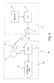
- Fig. 3 is a block diagram of the system of the present invention;
- Figs. 4A-C are schematic diagrams of the measuring unit of the present
invention;
- Fig. 5 is a schematic diagram of a launch tube, illustrating an adjustment
in a launch tube attitude that is required to compensate for a sensed
deviation at the time of projectile ejection;
- Fig. 6 is a block diagram representing the method of generating a
resultant impulse vector from sensed deviation values;
- Fig. 7 is a schematic diagram of a portion of a projectile body, illustrating
the configuration of the flight correction unit;
- Fig. 8 is a schematic diagram of the generation of a resultant impulse
vector from two impulse components;
- Fig. 9 is a side cross sectional view of a sensor for measuring the angular
rotation of a projectile in flight, in accordance with the present invention;
- Fig. 10 is a front view of the angular rotation sensor of Fig. 9; and
- Fig. 11 is a cross sectional view of a launch tube in which a projectile is
loaded, showing means for preventing rotation of the projectile within
the launch tube.
Detailed Description of Preferred Embodiments
The present invention relates to a method and system for adjusting the flight
path of an unguided projectile, immediately after launching, in order to
compensate for inaccuracies that result from barrel recoil or jittering during
the projectile firing. It will be understood that the term "jittering" throughout
the specification also refers to recoil.
Fig. 1 schematically illustrates an exemplary projectile launcher, generally
designated by numeral 10, in which a projectile, generally designated by
numeral 30, is loaded. Launcher 10 may be fixed onto the barrel of a rifle, may
be an independent unit, may be portable such as being a shoulder-carried
launcher, or may be deployed in several types of naval or aircraft weaponry.
The illustrated projectile launcher 10, according to one embodiment of the
invention, is configured as a Davis gun for obtaining a reduced jittering, with a
solid propellant 12 and compensating mass 14 being loaded in launch tube 8,
rearward to projectile 30. However, the launcher 10 does not necessarily have
to be of this type and can be of any unguided projectile launcher known in the
art. During firing, projectile 30 is accelerated forward at a tremendously high
rate, which may be as much as 10,000 g for an aircraft-launched missile, and
propellant 12 is converted into a gaseous state, causing compensating mass 14
to be ejected rearward through the launch tube, thereby reducing the jittering
of launcher 10.
Although greatly reduced in the Davis type launcher, the jittering is
nevertheless noticeable and causes a deviation in the flight path from a
desired target.
Fig. 3 describes a block diagram of system 40 of the invention. With reference
to Figs. 1-3, the system of the present invention comprises the following
components, according to a preferred embodiment:
At the launcher:
- Measuring unit 16 for measuring at launching, parameters relating to the
deviation of the flight path jittering from the nominal direction;
- Ground processing unit 17 for (a) determining a compensating impulse
vector, which when applied to the projectile shortly after launching, is
capable of returning the projectile to the nominal flight path; and (b) for
generating signal 25 representative of said compensating impulse vector;
and
- Transmitter 18 for transmitting signal 25 to the projectile shortly after
launching;
At the projectile:
- Receiver 33 for receiving signal 25;
- Angular rotation sensor 35 for determining the angular orientation of
projectile 30 about longitudinal axis 31 thereof while in flight;
- Projectile processing unit 37 for adjusting the received signal 25, taking
into account the difference in angular rotation of the projectile;
- Flight correcting unit 32 for receiving said adjusted signal and generating
an impulse within the projectile in order to compensate its flight direction
for the launch tube jittering deviation. As will be further described
hereinafter, according to one embodiment of the invention, the
correcting unit comprises a plurality (two or more) of pyrotechnic
thrusters which are ignited at a predetermined time, in order to provide
the correcting thrust.
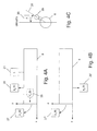
With reference to Figs. 4A-C, measuring
unit 16 comprises the following
sensors, which are mounted on launcher 10:
Following the firing of the projectile, sensor 21 senses that the projectile has
been ejected from the launch tube and accordingly provides data to ground
processing unit 17, which is indicative of the projectile ejection. Upon receiving
said data, ground processing unit 17 establishes ejection time t1. At ejection
time t1, measuring unit 16 senses three deviation values: angular sight
deviation A, launch tube attitude deviation ?á, which is a reflection of the
magnitude of the launch tube jittering, and projectile velocity deviation ?Vx, all
of which will be described hereinafter with respect to Fig. 6. The system of the
invention is adapted to generate a compensating impulse vector, which
compensates for each deviation so that the projectile may return to a nominal
flight path.
At time t1, sight angle sensor 29 determines the angular deviation A of
launcher sight 25. Ground processing unit 17 then reduces the angular
deviation A into components along the y and z axes, and first deviation value
42 (Fig. 6) is therefore determined.
The launch tube jitters at ejection time t1. Sensors 27 and 27' measure the
angular velocity along the x-y and x-z planes, respectively, of the launch tube
tip and sensors 28 and 28' measure the acceleration of the launch tube tip
along axes y and z, respectively, at time t1. Ground processing unit 17
integrates the sensed values of the acceleration and angular velocity
transmitted thereto by the corresponding sensors at ejection time t1 and
determines thereby the actual attitude á1 of the launch tube relative to a
horizontal plane H, which is schematically illustrated in Fig. 5, and the velocity
of the launch tube tip at time t1. The actual attitude is compared with the
nominal attitude and second deviation value 43 (Fig. 6) equal to launch tube
attitude deviation ?á, along each of the y and z axes, is determined.
Ground processing unit 17 also determines third deviation value 44 (Fig. 6)
concerning projectile velocity v1 along the x axis at ejection time t1, and
compares this value with the nominal velocity. The ground processing unit
determines a vector which compensates for the projectile velocity deviation in
the x axis, between v1 and the nominal velocity (?Vx), and reduces this
compensating vector into components in the y and z axes.
As shown in Fig. 6, processing unit 17 determines an impulse value, which is
equal to the product of the mass of the projectile and a difference in velocity,
for correcting each of the corresponding deviation values 42, 43 and 44, so
that the projectile may return to the nominal flight path and finally strike the
intended target. Processing unit 17 generates a pair of impulse components,
one on each of the y and z axes, for each of the deviation values, e.g. Iy2 and
Iz2. Each pair of impulse components is generated in such a way that if no
other deviation values resulted, the application of said pair of impulse
components onto the center of gravity (CG) of the projectile (Fig. 2) would
cause the projectile to return to its nominal flight path. For example, the
velocity difference associated with impulse component Iy2 is based on the
equation ΔV y =(y ˙+Vα), namely the sum of the instantaneous velocity along
the y axis of the launch tube, and the product of the instantaneous velocity of
the projectile along the y axis and the instantaneous attitude of the launch
tube á, which is actually an approximation of siná, all of the above measured
at time t1. Ground processing unit 17 then combines all of the impulse
components along the y axis to produce combined impulse component Iy and
combines all of the impulse components along the z axis to produce combined
impulse component Iz. A weighted impulse vector Iw is then generated from
combined impulse components Iy and Iz. Ground processing unit 17 then
generates a signa! 25 representative of said weighted impulse vector, and
transmits this signal via transmitter 18 (Fig. 3) to the projectile in flight.
As shown in Fig. 3, signal 25 is transmitted to receiver 33 carried by the
projectile. According to the present invention, this signal is transmitted very
shortly after launching, in the range of approximately 0.2 seconds after firing,
in order to minimize inaccuracies. Signal 25 may be transmitted by wireless
means, by a fiber optic cable connecting transmitter 18 and receiver 33, which
is severed shortly after ejection of the projectile from the launch tube, or any
other means of communication well known to those skilled in the art.
Projectile processing unit 37 receives signal 25 and commands flight correcting
unit 32 to apply the compensating impulse vector at the correct instant, so
that the actual flight path of the projectile may be corrected to coincide with
the nominal flight path and so that the projectile warhead may accurately
strike a selected target. Flight path correction in accordance with the present
invention is dependent upon accurate application of the compensating impulse
vector. Since the projectile rotates about its longitudinal axis while in flight in
order to reduce drifting, flight correcting unit 32 rotates as well. If the angular
displacement of the flight correcting unit following projectile ejection time t1
were unknown, the compensating impulse vector would be liable to be applied
at an incorrect direction, and the flight path would not be corrected. Projectile
processing unit 37 receives data from angular rotation sensor 35 concerning
the angular displacement of the projectile following time t1, and accordingly
adjusts the impulse vector that is to be applied to the projectile. The adjusted
impulse vector that is to be applied to the projectile is weighted impulse vector
Iw combined with an incremental impulse vector that takes into account the
difference in angular position of the flight correcting unit between time t1 and
the time at which flight correction is effected, hereinafter referred to as time
t2.
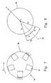
Fig. 7 illustrates a preferred embodiment of flight correcting unit 32. Flight
correcting unit 32 is mounted on a cylindrical portion 45 of the projectile body,
which is preferably, but not necessarily at the rear of the projectile. Flight
correcting unit 32 comprises a plurality of pyrotechnic thrusters 47, e.g.
miniature jet engines, each of which is mounted to the portion 45 of the
projectile body, at a different orientation with respect to longitudinal axis 31 of
the projectile (Fig. 2) such that the axis of each of said thrusters crosses
longitudinal axis 31 of the projectile. Five pyrotechnic thrusters 47 are shown,
but it will be appreciated that any other number of thrusters from two to five
which is suitable for controlling the magnitude and direction of the adjusted
impulse vector may be similarly employed. The projectile rotates about its
longitudinal axis while in flight at a typical angular rate ù of approximately 5-10
Hz, and this rotational rate may be utilized to fire a thruster at a precise
angle which is predetermined by processing unit 37. Therefore thrusters 47
are not adapted to accelerate the projectile any more than the acceleration
imparted by the launcher, but rather are used to change the orientation of the
projectile, so that it may accurately impact a selected target. By one-time
firing of a selected number of thrusters, and at the appropriate orientation, the
magnitude and direction of the adjusted impulse vector are controllable.
Fig. 8 schematically depicts the generation of an adjusted impulse vector I.
Two thrusters separated by an angular distance of 2â were fired. Since each
thruster is identical, the impulse vector generated by each thruster has an
equal magnitude of I1 and is directed inward to center C of portion 45 of the
projectile body. The resultant impulse vector I is equal to 2 I1sinâ and is
collinear with the centerline 49 between the two thrusters, directed outwardly
from center C. It will be appreciated that any other number of thrusters may
be fired, and the resultant impulse vector will be similarly determined from the
total number of individual components.
As described hereinabove, accurate measurement of the angular position of
each thruster is needed for compensation of launch tube jittering. Figs. 9 and
10 illustrate angular rotation sensor 35, which is used to measure the angular
displacement of the projectile about its longitudinal axis. Angular rotation
sensor 35 comprises disc 51 provided with collar 57, which is coaxial with
longitudinal axis 31 of the projectile. Collar 57 facilitates the mounting of disc
51 on bearing block 53, which is fixedly attached to fuselage 58 of the
projectile by means of adaptor 54, so that disc 51 is rotatable about bearing
block 53. The rim of disc 51 is provided with a weighted portion 56, which is
adapted to reduce the angular velocity of disc 51. Weighted portion 56 is
normally separated from an abutment surface (not shown), which is a part of
the fuselage. Disc 51 is formed with a plurality of apertures 63, which are
formed at a uniform radial distance from disc center 64 and are at a fixed
angular distance with respect to centerline 65 one from the other. Light
detector 61, e.g. an encoder, is mounted onto fuselage 58 and emits a beam
of light that is directed to one of the apertures.
During launching, the projectile is accelerated within the launch tube and is
prevented from rotating, so that the angular orientation of a datum provided
with disc 51 may be determined at ejection time t1. As shown in Fig. 11, one
or more protrusions 67 radially protrude from fuselage 58 of the projectile.
These protrusions 67 are insertable, during loading of the projectile, in
complementary grooves 69 formed in the tubular inner wall of launch tube 8.
During forward propulsion of the projectile, protrusions 67 slide within grooves
69, and the projectile is therefore prevented from rotating within launch
tube 8.
Referring back to Figs. 9 and 10, disc 51 is pressed to the abutment surface as
a result of the acceleration of the projectile during launching and is therefore
unable to rotate. Upon ejection of the projectile from the launch tube at time
t1, the projectile ceases to accelerate and is propelled along a flight path under
the influence of momentum, as a result of its initial velocity V1 at time t1, and
of gravity. Since disc 51 ceases to be accelerated after being ejected from the
launch tube, it is no longer pressed against the abutment surface and is
therefore free to rotate. While the projectile begins to rotate about its
longitudinal axis after ejection, due to the configuration of the projectile and to
the airstreams that pass therearound, the angular rotation of disc 51 is
significantly limited by weighted portion 56, e.g. is on the order of
approximately 1 revolution per hour. Thus disc 51 may be considered
stationary relative to fuselage 58. Since light detector 61 is connected to
fuselage 58, in-flight rotation of the projectile about its longitudinal axis results
in rotation of the light detector about the longitudinal axis of the projectile.
Light emitted from light detector 61 onto apertures 63 of the relatively
stationary disc 51 is therefore indicative of the degree of angular rotation of
the disc. Light detector 61 transmits the data concerning the angular
difference of datum 66 from time t1, at which the projectile begins to rotate
relative to the disc, to predetermined flight path correction time t2 to
processing unit 37 (Fig. 3), whereupon the signal received from transmitter 18
is adjusted and the adjusted impulse vector is applied to the projectile center
of gravity by means of flight correcting unit 32, as described hereinabove.
Optionally, projectile processing unit 37 may also adjust a compensating
impulse vector by taking into account the time difference between ejection
time t1 and the flight path correction time t2. Signal 25 is representative of the
compensating impulse vector, which is generated by ground processing unit 17
(Fig. 3), in order to correct the projectile position at time t1 due to the
presence of deviation values 42, 43 and 44 (Fig. 6). However, the projectile
position invariably changes from time t1 to time t2, a time of approximately
0.05 sec, and therefore the resultant impulse vector I (Fig. 8) generated at
flight path correction time t2 may result in an inaccurate strike. A clock (not
shown), which is in communication with projectile processing unit 37 (Fig. 3),
measures the time difference between t1 and t2. Projectile processing unit 37
(Fig. 3) accordingly adjusts the required impulse vector based on the
difference in the projectile position between t1 and t2.
While some embodiments of the invention have been described by way of
illustration, it will be apparent that the invention can be carried into practice
with many modifications, variations and adaptations, and with the use of
numerous equivalents or alternative solutions that are within the scope of
persons skilled in the art, without departing from the spirit of the invention or
exceeding the scope of the claims.