EP1599135B1 - Nerve stimulation functionality indicator apparatus - Google Patents
Nerve stimulation functionality indicator apparatus Download PDFInfo
- Publication number
- EP1599135B1 EP1599135B1 EP04705589.2A EP04705589A EP1599135B1 EP 1599135 B1 EP1599135 B1 EP 1599135B1 EP 04705589 A EP04705589 A EP 04705589A EP 1599135 B1 EP1599135 B1 EP 1599135B1
- Authority
- EP
- European Patent Office
- Prior art keywords
- needle
- current
- nerve stimulation
- nerve
- display
- Prior art date
- Legal status (The legal status is an assumption and is not a legal conclusion. Google has not performed a legal analysis and makes no representation as to the accuracy of the status listed.)
- Expired - Lifetime
Links
- 230000007383 nerve stimulation Effects 0.000 title claims description 20
- 210000005036 nerve Anatomy 0.000 claims description 63
- 230000007246 mechanism Effects 0.000 claims description 8
- 210000000578 peripheral nerve Anatomy 0.000 claims description 7
- 230000005611 electricity Effects 0.000 claims description 3
- 238000000034 method Methods 0.000 description 17
- 238000010586 diagram Methods 0.000 description 6
- 238000004891 communication Methods 0.000 description 5
- 230000008569 process Effects 0.000 description 5
- 230000000638 stimulation Effects 0.000 description 5
- 230000004075 alteration Effects 0.000 description 4
- 230000000694 effects Effects 0.000 description 4
- 238000013459 approach Methods 0.000 description 3
- 210000003205 muscle Anatomy 0.000 description 3
- 230000003466 anti-cipated effect Effects 0.000 description 2
- 230000008901 benefit Effects 0.000 description 2
- 239000004020 conductor Substances 0.000 description 2
- 230000008878 coupling Effects 0.000 description 2
- 238000010168 coupling process Methods 0.000 description 2
- 238000005859 coupling reaction Methods 0.000 description 2
- 230000006378 damage Effects 0.000 description 2
- 238000001514 detection method Methods 0.000 description 2
- 239000004973 liquid crystal related substance Substances 0.000 description 2
- 239000003589 local anesthetic agent Substances 0.000 description 2
- 230000003340 mental effect Effects 0.000 description 2
- 238000012986 modification Methods 0.000 description 2
- 230000004048 modification Effects 0.000 description 2
- 230000004044 response Effects 0.000 description 2
- 230000011664 signaling Effects 0.000 description 2
- 238000012360 testing method Methods 0.000 description 2
- 230000000007 visual effect Effects 0.000 description 2
- 206010002091 Anaesthesia Diseases 0.000 description 1
- 206010028347 Muscle twitching Diseases 0.000 description 1
- 206010036437 Posturing Diseases 0.000 description 1
- 208000027418 Wounds and injury Diseases 0.000 description 1
- 230000037005 anaesthesia Effects 0.000 description 1
- 230000005540 biological transmission Effects 0.000 description 1
- 230000001149 cognitive effect Effects 0.000 description 1
- 239000003086 colorant Substances 0.000 description 1
- 230000036461 convulsion Effects 0.000 description 1
- 230000003247 decreasing effect Effects 0.000 description 1
- 208000002925 dental caries Diseases 0.000 description 1
- 239000000835 fiber Substances 0.000 description 1
- 208000014674 injury Diseases 0.000 description 1
- 230000007257 malfunction Effects 0.000 description 1
- 230000004118 muscle contraction Effects 0.000 description 1
- 230000003287 optical effect Effects 0.000 description 1
- 239000013307 optical fiber Substances 0.000 description 1
- 238000002106 pulse oximetry Methods 0.000 description 1
- 230000009467 reduction Effects 0.000 description 1
- 238000002694 regional anesthesia Methods 0.000 description 1
- 230000001755 vocal effect Effects 0.000 description 1
Images


Classifications
-
- A—HUMAN NECESSITIES
- A61—MEDICAL OR VETERINARY SCIENCE; HYGIENE
- A61N—ELECTROTHERAPY; MAGNETOTHERAPY; RADIATION THERAPY; ULTRASOUND THERAPY
- A61N1/00—Electrotherapy; Circuits therefor
- A61N1/18—Applying electric currents by contact electrodes
- A61N1/32—Applying electric currents by contact electrodes alternating or intermittent currents
- A61N1/36—Applying electric currents by contact electrodes alternating or intermittent currents for stimulation
- A61N1/372—Arrangements in connection with the implantation of stimulators
- A61N1/37211—Means for communicating with stimulators
- A61N1/37252—Details of algorithms or data aspects of communication system, e.g. handshaking, transmitting specific data or segmenting data
- A61N1/37282—Details of algorithms or data aspects of communication system, e.g. handshaking, transmitting specific data or segmenting data characterised by communication with experts in remote locations using a network
-
- A—HUMAN NECESSITIES
- A61—MEDICAL OR VETERINARY SCIENCE; HYGIENE
- A61N—ELECTROTHERAPY; MAGNETOTHERAPY; RADIATION THERAPY; ULTRASOUND THERAPY
- A61N1/00—Electrotherapy; Circuits therefor
- A61N1/02—Details
- A61N1/04—Electrodes
- A61N1/05—Electrodes for implantation or insertion into the body, e.g. heart electrode
- A61N1/0551—Spinal or peripheral nerve electrodes
-
- A—HUMAN NECESSITIES
- A61—MEDICAL OR VETERINARY SCIENCE; HYGIENE
- A61N—ELECTROTHERAPY; MAGNETOTHERAPY; RADIATION THERAPY; ULTRASOUND THERAPY
- A61N1/00—Electrotherapy; Circuits therefor
- A61N1/18—Applying electric currents by contact electrodes
- A61N1/32—Applying electric currents by contact electrodes alternating or intermittent currents
- A61N1/36—Applying electric currents by contact electrodes alternating or intermittent currents for stimulation
- A61N1/36014—External stimulators, e.g. with patch electrodes
- A61N1/36021—External stimulators, e.g. with patch electrodes for treatment of pain
-
- A—HUMAN NECESSITIES
- A61—MEDICAL OR VETERINARY SCIENCE; HYGIENE
- A61N—ELECTROTHERAPY; MAGNETOTHERAPY; RADIATION THERAPY; ULTRASOUND THERAPY
- A61N1/00—Electrotherapy; Circuits therefor
- A61N1/18—Applying electric currents by contact electrodes
- A61N1/32—Applying electric currents by contact electrodes alternating or intermittent currents
- A61N1/36—Applying electric currents by contact electrodes alternating or intermittent currents for stimulation
- A61N1/372—Arrangements in connection with the implantation of stimulators
- A61N1/37211—Means for communicating with stimulators
- A61N1/37235—Aspects of the external programmer
- A61N1/37247—User interfaces, e.g. input or presentation means
Landscapes
- Health & Medical Sciences (AREA)
- Engineering & Computer Science (AREA)
- Biomedical Technology (AREA)
- Nuclear Medicine, Radiotherapy & Molecular Imaging (AREA)
- Radiology & Medical Imaging (AREA)
- Life Sciences & Earth Sciences (AREA)
- Animal Behavior & Ethology (AREA)
- General Health & Medical Sciences (AREA)
- Public Health (AREA)
- Veterinary Medicine (AREA)
- Infusion, Injection, And Reservoir Apparatuses (AREA)
- Electrotherapy Devices (AREA)
Description
- This invention relates generally to nerve stimulation with electric current.
- Anesthesiologists often use nerve stimulation to localize a desired nerve or nerves prior to administration of a local anesthetic (Von Perthes is generally credited with providing the original description of using peripheral nerve stimulators for regional anesthesia in 1912). Nerve stimulation typically utilizes electric current to elicit visible muscle twitches as a result of stimulation of the nerve or nerves to thereby confirm proximity of the needle to the nerve. This technique relies generally upon two phenomena. First, that many nerves, when properly stimulated by electric current, will cause a corresponding substantially predictable movement (such as a twitch) of a portion of the patient's body (in particular, muscle contractions resulting from stimulation of the nerve(s)). Second, that the amount of electric current required to cause the desired muscle movement will vary predictably with distance between the tip of the needle that sources the electric current and the nerve.
- Stimulation typically begins with a higher intensity current (such as, for example, 1.5 to 2.0 milliamperes). Upon observing the anticipated muscle movement (thereby indicating that the needle is positioned within a given distance from the nerve, the current is reduced and the process repeated until the current has been reduced to a predetermined range (such as 0.2 to 0.5 milliamperes), thereby indicating that the needle is within a clinically relevant distance from the nerve to best facilitate the anesthesia of the nerve after introduction of a local anesthetic via the needle. When conducting this kind of procedure, it is important to avoid contacting or piercing the nerve with the needle as this can cause injury to the nerve. Generally, stimulation of the nerve with low current intensity (e.g., less than 0.5 milliamperes) indicates an intimate needle-nerve relationship and advancing the needle closer to the nerve after the stimulation is achieved at less than 0.5 milliamperes caries a risk of contacting or piercing the nerve.
- The procedure typically requires two people. One person handles manipulation of the needle and observes the patient's response while the second person operates the remote peripheral nerve stimulator apparatus and visually monitors the current delivered. In particular, the latter person controls the amount of current being applied via the needle (as well as other parameters that pertain to the current being provided). For a variety of good reasons (e.g., lack of space, difficulty of placing the stimulator on the patient, preserving the sterile field, and so forth) the remote peripheral nerve stimulator itself is usually located at a certain distance away from the patient and the person manipulating the needle. The person manipulating the needle therefore must manage a considerable degree of cognitive loading; they must physically manipulate the needle in a careful fashion while also observing the anticipated muscle response and also while remaining cognizant of the present amount of current being delivered via the needle. This person typically keeps verbally informing the person performing the block of the intensity of the current being delivered, so that the person performing the block does not have to frequently shift their gaze from the procedure to the display on the nerve stimulator and thus be distracted from the procedure. This can still require, in many instances, a considerable amount of frequent gaze shifting and/or repositioning by the person performing the procedure, particularly when the current gauge (or other indicator) on the nerve stimulator apparatus is located some distance away from the needle operator. Not surprisingly such physical and mental challenges give rise to a situation where errors are more likely to occur. These errors can be a direct result of the need for gaze alteration and distraction and typically include unwanted needle movement during gazing, which in turn may result in failure to anesthetize the nerve or piercing the nerve when the needle is inadvertently pushed deeper or pulled back more superficially from its original location. In addition, even when a single person performs the block and manipulates the stimulator at the same time (rare, but possible by use of a remote controller of the nerve stimulator, such as a foot pedal), the need to constantly shift one's gaze between the patient, needle, procedure, and the display on the nerve stimulator can still be very distracting.
- The above approach is encumbered with other concerns and issues as well. For example, it is possible for the needle operator to insert the needle into the patient and to begin to manipulate it before the nerve stimulator apparatus operator has begun to provide current to the needle. It is also possible for the supply of electric current to fail during the procedure, such that the needle operator continues to manipulate the needle while unaware of this condition. Such conditions can result in discomfort and/or harm to the patient and/or an unsuccessful procedure. As another example, it is possible for the cord that couples the nerve stimulator apparatus to the needle to be improperly coupled to one or the other device or to become partially or fully disconnected during the procedure. This can result in either a complete failure to deliver current to the needle or a partial failure (where, for example, only a portion of the indicated current is actually being delivered to the needle). It is also possible for miscommunication to occur between the operator of the needle and the person operating the nerve stimulator, resulting in decisions made by the person operating the needle being inconsistent with the actual present electric current intensity.
- Nerve stimulator devices typically have at least one indicator to represent the operational status of the machine. Light emitting diode meters, liquid crystal displays, flashing diodes, gauges of various types, and audible beeps, for example, have all been used to monitor current availability and/or to signal a malfunction. Such remotely placed indicia, unfortunately, doesn't always adequately serve the operator who manipulates the needle. Tight operating quarters and physical remoteness of the nerve stimulator machine can make it difficult for the needle operator to accurately view such visible displays, as can the required physical positioning and posturing of the needle operator during a given procedure. Furthermore, audible alerts are easily confused with other ordinary sounds of the operating theater (for example, patients receiving a nerve block are usually monitored by pulse oximetry which is also typically accompanied by an audible beeping sound).
-
US 4,515,168 A andUS 2002/065481 A1 disclose nerve stimulator needles, but do not disclose a stimulator needle with a remote peripheral nerve stimulator with an associated needle functionality indicator at the needle to indicate the status of the nerve stimulator to a person handling the needle whilst another person controls the nerve stimulator. - According to the present invention, there is provided a nerve stimulation needle comprising: a hand graspable hub, by which one person typically handles manipulation of a needle operably coupled to the hand graspable hub; an electrical tether to operably electrically couple the needle to a remote peripheral nerve stimulator which a second person typically operates to control the amount of current being applied via the needle; display means for determining an amount of current being presently provided to the needle and for providing corresponding information to a needle functionality indicia such that the needle functionality indicia corresponds to the amount of current then being presently provided to the needle, wherein the needle functionality indicia is disposed on the hand graspable hub, such that the one person can readily determine the amount of current presently being provided under the control of the second person.
- To enable a better understanding of the present invention, and to show how the same may be carried into effect, reference will now be made, by way of example only, to the accompanying drawings, in which:-
-
FIG. 1 comprises a system block diagram as configured in accordance with various embodiments of the invention; -
FIG. 2 comprises a block diagram of a needle hub as configured in accordance with an embodiment of the invention; -
FIG. 3 comprises a flow diagram as configured in accordance with an embodiment of the invention; -
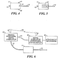
FIG. 4 comprises a detail block diagram as configured in accordance with an embodiment of the invention; -
FIG. 5 comprises a detail block diagram as configured in accordance with another embodiment of the invention; and -
FIG. 6 comprises a system block diagram as configured in accordance with yet another embodiment of the invention. - Skilled artisans will appreciate that elements in the figures are illustrated for simplicity and clarity and have not necessarily been drawn to scale. For example, the dimensions of some of the elements in the figures may be exaggerated relative to other elements to help to improve understanding of various embodiments of the present invention. Also, common but well-understood elements that are useful or necessary in a commercially feasible embodiment are typically not depicted in order to facilitate a less obstructed view of these various embodiments of the present invention.
- The above needs are at least partially met through provision of the nerve stimulation functionality indicator apparatus and method as described in the following detailed description, particularly when studied in conjunction with the drawings.
- Generally speaking, pursuant these various embodiments, a nerve stimulator operational status display is disposable in an operational mode substantially distal to the nerve stimulator (thereby permitting its placement in a more convenient location for the person manipulating the needle). This display couples to the nerve stimulator via an appropriate nerve stimulator operational status information communication path. In certain embodiments, the display may be provided integral to the needle (such as, for example, by comprising a part of a hand graspable hub of the needle).
- In various embodiments, the nerve stimulator operational status information communication path can comprise any of an electrical conductor, an optical conduit, and/or a wireless channel.
- The display can present signal indicia and/or alphanumeric information regarding current as being delivered to the needle. Depending upon the embodiment, the display can also provide information regarding current presence and/or polarity of the current being provided. In some embodiments, color serves to indicate the amount of current being provided to the needle.
- So configured, the needle operator can readily remain apprised of various data regarding the provision of current to the needle without needing to significantly alter his or her posture, position, or general field of view. Furthermore, the needle operator can receive accurate and timely information regarding the present availability of current and the polarity of the corresponding voltage potential, thereby avoiding inappropriate manipulation of the needle when current becomes unavailable or unsuitable for whatever reason.
- Referring now to the drawings, and in particular to
FIG. 1 , a remote peripheral nerve stimulator as is generally known in the art couples via anelectrical tether 12 to a nerve stimulation needle comprised of a handgraspable hub 11 and aneedle 13. In this embodiment, theelectrical tether 12 couples to and extends outwardly of the handgraspable hub 11. In this embodiment, the handgraspable hub 11 also includesneedle functionality indicia 14 comprising non-alphanumeric visible indicia. As depicted, in this embodiment, the visible indicia comprises a discrete representational indicia such as, for example, a light emitting diode. In a preferred embodiment, the light emitting diode would comprise a multi-color light emitting diode (or a multitude of various colored diodes) such that different displayed colors can be used to represent different corresponding amounts of current then being provided to the needle as described in more detail herein. In addition, such a discrete indicia can also serve to present information regarding a presence or absence of electrical current and/or the polarity of electricity then being provided to the needle. - With reference now to
FIG. 2 , thenerve stimulator needle 11 can include a current sense unit 21 (with polarity detection capability too, if desired) to detect the presence and amount of current being provided by the nerve stimulator to the needle. Any number of known current detection circuits can be utilized to enable this capability. Thecurrent sense unit 21 provides its locally developed information to alogic unit 22 where a determination can be made regarding the presence and amount of current then being provided to the needle and for then correlating that determination to a particular corresponding visual indication. Thelogic unit 22 can be a programmable platform, a hard-wired logic circuit, or a combination of both as well understood in the art. Thelogic unit 22 then provides the information via a coupling circuit (such coupling circuits being well known in the art) to display information to adisplay driver 23 which then causes the information to be displayed by the display 24 (or displays where more than one display is provided). For example, when thedisplay 24 comprises a multicolor light emitting diode as disclosed above, thelogic unit 22 can identify the specific color that will serve to represent the detected current level and thedisplay driver 23 can translate that selection into specific trigger signals that cause the light emitting diode to glow with that particular color. -
FIG. 3 serves to illustrate one approach to such an embodiment. Thelogic unit 22 can optionally test 30 for the presence of current as described above. Upon determining that no current is presently being provided, thelogic unit 22 can effect adisplay 31 that corresponds to such a determination (for example, by extinguishing the light emitting diode). When current is present, thelogic unit 22 can also optionally test 32 the polarity of the connection between thenerve stimulator 10 and the nerve stimulator needle. When incorrect polarity is evident, thelogic unit 22 can effect an appropriatecorresponding display 33. When current is present and the electric connection has appropriate polarity, thelogic unit 22 then determines the amount of current that is present. In this illustrative embodiment, when more than 1.0 milliamperes is present 34, a green display is provided 35 through appropriate control of the multi-color light emitting diode. When less than 1.0 milliamperes but more than 0.5 milliamperes is detected 36, ayellow display 37 can be provided. And, when less than 0.5 milliamperes is detected 36, a red colored display can be provided 38. - So configured, the needle operator can readily determine what level of current is presently being utilized without needing to find and observe the
nerve stimulator 10 itself. Instead, thedisplay 14 on thehub 11 can be readily viewed to obtain such information. - Also, optionally, the needle operator can become similarly apprised of the general presence or absence of current and/or the polarity of the electricity being delivered to the nerve stimulator needle, again without needing to substantially break attention and focus with respect to manipulation of the needle itself.
- In the illustrative examples above, only a single visual point source serves to provide the desired information. Other configurations are of course possible. For example, with reference to
FIG. 4 , additional selectably illuminableindicia 41 and 42 can be additionally disposed on thehub 11. Such additional indicia can serve to better accommodate a wider range of useful viewing angles such that the needle operator can be assured a useful view of a display from many different working perspectives almost regardless of the needle operator's position with respect to thehub 11. As another example, and referring now toFIG. 5 , other kinds of displays can also be used including, for example, an alphanumeric or othergraphic element display 51. Such adisplay 51 can be embodied by a liquid crystal display or any other functionally similar display that meets the needs and requirements of a given implementation. Such a display can serve to directly display a specific amount of current as is then being provided to the needle. In addition (or in lieu thereof, such a display can use color as otherwise suggested above to provide information regarding the present operational status of the needle's current. - In the various embodiments described above, the display comprises an integral part of the nerve stimulator needle. In examples not forming part of the claimed invention, however, the display may be separate from the nerve stimulator needle and also remote from the
nerve stimulator 10. For example, and referring now toFIG. 6 , a separate and discrete nerve stimulator operational status display 60 (preferably as provided with its own discrete housing) can couple to the nerve stimulator independent of the needle via a dedicated nerve stimulator operational statusinformation communication path 61. This path can comprise, as desired, an electrical conductor, an optical fiber, and/or a wireless communications channel 64 (including any of radio frequency-based signaling such as a Bluetooth-compatible channel, infrared-based signaling, and so forth) when both thenerve stimulator 10 and thedisplay 60 are appropriately equipped with the necessary transmission and reception capability (represented here by the optional inclusion of antenna as denoted byreference numerals 62 and 63). - So configured, during operational use, the
display 60 can be disposed remote from thenerve stimulator 10 and proximal to a desired viewing location as determined, for example, by the needle operator. If desired, to facilitate such placement, thedisplay 60 can be further equipped with an attachment mechanism 65 (such as Velcro-style hooks or loops, pins, snaps, clips, or any other attachment mechanism as may be presently known or hereafter developed). Thedisplay 60, of course, can be otherwise configured as described and suggested above to thereby provide all of the same benefits and advantages in a potentially more convenient-to-view example. - Again, it can be seen that all of these embodiments serve generally to permit a needle operator to effect the nerve stimulation process with greater certainty and less physical and mental challenge than was previously possible under most normal circumstances. In general this should result in more rapid completion of the process and a reduction in overall discomfort for the patient.
- Such embodiments not only improve the convenience by which a needle operator can obtain information regarding the operational status of the nerve stimulation process, they can also be used to facilitate a positive alteration of the nerve stimulation process itself. For example, instead of functioning as potentially both a receiver of information from and a provider of instructions to the nerve stimulator operator, the needle operator can more intuitively rely upon the displayed information to remain apprised of current operating conditions such that the dialogue between the two operators can comprise more unambiguously a series of instructions from the needle operator to the nerve stimulator operator.
- Those skilled in the art will recognize that a wide variety of modifications, alterations, and combinations can be made with respect to the above described embodiments without departing from the scope of the invention as defined by the claims, and that such modifications, alterations, and combinations are to be viewed as being within the ambit of the inventive concept.
- For example, the embodiments presented describe a display mechanism that is driven by an active logic capability that is remote from the
nerve stimulator 10. If desired, of course, such logic capability could be disposed within thenerve stimulator 10 and the extracted information then communicated to the display. This could be accomplished via an active reception and decoding capability or more passively if desired (for example, a fiber optic cable could be used to transmit indicia light from thenerve stimulator 10 to a viewing point on the nerve stimulator needle or on the discrete and separate display housing to essentially permit remote viewing of an indicator light that is located back with the nerve stimulator 10). - As another example, flashing one or more portions of a given display can be used to indicate either correct operation or incorrect operation. For example, a flashing light emitting diode could be used to indicate the presence of current (or the absence thereof) and an extinguished diode could be used to indicate the opposite condition.
- And as yet another example, a user input mechanism (such as a
multi-position switch 15 as is shown depicted in phantom lines inFIG. 1 to denote its optional status) can be provided on the needle (and, in a preferred approach, on the hub 11). Such a mechanism could be used by the person manipulating the needle to provide information, such as instructions regarding the provision of electric current, to the nerve stimulator operator. Such instructions could indicate, for example, that the nerve stimulator operator should increase the electrical current, decrease the electrical current, or maintain the electrical current at a particular level (for example, amulti-position switch 15, such as a wheel switch that is biased to return to a return point, could be rotated in one direction to indicate that current should be decreased, rotated slightly in the opposite direction to indicate that the current should be maintained at a present level, and rotated fully in the opposite direction to indicate that the current should be increased). So configured, the needle operator would have an additional option of communicating specific instructions to the nerve stimulator operator via this mechanism. Such a capability could be useful in a variety of circumstances, and particularly so when the immediate vicinity of the patient becomes sufficiently noisy that verbal communications between the needle operator and the nerve stimulator operator are rendered more difficult.
Claims (10)
- A nerve stimulation needle comprising:- a hand graspable hub (11), by which one person typically handles manipulation of a needle (13) operably coupled to the hand graspable hub;- an electrical tether (12) to operably electrically couple the needle to a remote peripheral nerve stimulator (10) which a second person typically operates to control the amount of current being applied via the needle (13);- display means (22, 23) for determining an amount of current being presently provided to the needle (13) and for providing corresponding information to a needle functionality indicia (14, 24, 41, 42, 51) such that the needle functionality indicia (14, 24, 41, 42, 51) corresponds to the amount of current then being presently provided to the needle (13), wherein the needle functionality indicia (14, 24, 41, 42, 51) is disposed on the hand graspable hub (11), such that the one person can readily determine the amount of current presently being provided under the control of the second person.
- The nerve stimulation needle of claim 1 wherein the needle functionality indicia (14) comprises, at least in part, a visible indicia (24, 41, 42, 51).
- The nerve stimulation needle according to claim 2, wherein the needle functionality indicia is a graphic element display (51).
- The nerve stimulation needle of claim 3 wherein the needle functionality indicia is an alphanumeric display (51) which presents information regarding a presence and absence of electrical current to the needle (13) via the electrical tether (12).
- The nerve stimulation needle of claim 4 wherein the alphanumeric display (51) presents information regarding polarity of electricity then being provided to the needle (13) via the electrical tether (12).
- The nerve stimulation needle of any preceding claim further comprising a user input mechanism (15) that may be used by a person manipulating the needle (13) to provide information to an operator of the nerve stimulator (10), being the second person.
- The nerve stimulation needle of claim 6 wherein the information comprises an instruction to the operator of the nerve stimulator (10) regarding the electrical current.
- The nerve stimulation needle of claim 7 wherein the instruction comprises at least one of an indication to:- increase the electrical current;- maintain the electrical current at a present level; and- decrease the electrical current.
- The nerve stimulation needle of claim 6, 7 or 8 wherein the user input mechanism (15) comprises a multi-position switch.
- The nerve stimulation needle of any preceding claim wherein the needle functionality indicia comprises a multi-color display (14, 24, 41, 42, 51, 60).
Applications Claiming Priority (3)
| Application Number | Priority Date | Filing Date | Title |
|---|---|---|---|
| US375678 | 2003-02-27 | ||
| US10/375,678 US7689292B2 (en) | 2003-02-27 | 2003-02-27 | Nerve stimulation functionality indicator apparatus and method |
| PCT/US2004/002081 WO2004075973A2 (en) | 2003-02-27 | 2004-01-27 | Nerve stimulation functionality indicator apparatus and method |
Publications (3)
| Publication Number | Publication Date |
|---|---|
| EP1599135A2 EP1599135A2 (en) | 2005-11-30 |
| EP1599135A4 EP1599135A4 (en) | 2010-01-13 |
| EP1599135B1 true EP1599135B1 (en) | 2017-03-29 |
Family
ID=32907859
Family Applications (1)
| Application Number | Title | Priority Date | Filing Date |
|---|---|---|---|
| EP04705589.2A Expired - Lifetime EP1599135B1 (en) | 2003-02-27 | 2004-01-27 | Nerve stimulation functionality indicator apparatus |
Country Status (5)
| Country | Link |
|---|---|
| US (1) | US7689292B2 (en) |
| EP (1) | EP1599135B1 (en) |
| AU (1) | AU2004216271B2 (en) |
| CA (1) | CA2515787C (en) |
| WO (1) | WO2004075973A2 (en) |
Families Citing this family (15)
| Publication number | Priority date | Publication date | Assignee | Title |
|---|---|---|---|---|
| US10342452B2 (en) | 2004-07-29 | 2019-07-09 | Medtronic Xomed, Inc. | Stimulator handpiece for an evoked potential monitoring system |
| DE102008038908A1 (en) * | 2008-08-13 | 2010-02-18 | Universitätsklinikum Heidelberg | Suction device for aspirating fluid during a surgical procedure |
| US9364277B2 (en) | 2012-12-13 | 2016-06-14 | Cook Medical Technologies Llc | RF energy controller and method for electrosurgical medical devices |
| US9204921B2 (en) | 2012-12-13 | 2015-12-08 | Cook Medical Technologies Llc | RF energy controller and method for electrosurgical medical devices |
| WO2014145548A2 (en) | 2013-03-15 | 2014-09-18 | Concert Medical, Llc | Method and system for controllably administering fluid to a patient and/or for controllably withdrawing fluid from the patient |
| US10098585B2 (en) | 2013-03-15 | 2018-10-16 | Cadwell Laboratories, Inc. | Neuromonitoring systems and methods |
| US10123731B2 (en) | 2014-08-08 | 2018-11-13 | Medtronic Xomed, Inc. | Wireless sensors for nerve integrity monitoring systems |
| WO2016032931A1 (en) | 2014-08-26 | 2016-03-03 | Avent, Inc. | Method and system for identification of source of chronic pain and treatment |
| US10039915B2 (en) | 2015-04-03 | 2018-08-07 | Medtronic Xomed, Inc. | System and method for omni-directional bipolar stimulation of nerve tissue of a patient via a surgical tool |
| US10445466B2 (en) | 2015-11-18 | 2019-10-15 | Warsaw Orthopedic, Inc. | Systems and methods for post-operative outcome monitoring |
| US10339273B2 (en) | 2015-11-18 | 2019-07-02 | Warsaw Orthopedic, Inc. | Systems and methods for pre-operative procedure determination and outcome predicting |
| US10849517B2 (en) | 2016-09-19 | 2020-12-01 | Medtronic Xomed, Inc. | Remote control module for instruments |
| US9935395B1 (en) | 2017-01-23 | 2018-04-03 | Cadwell Laboratories, Inc. | Mass connection plate for electrical connectors |
| US11253182B2 (en) | 2018-05-04 | 2022-02-22 | Cadwell Laboratories, Inc. | Apparatus and method for polyphasic multi-output constant-current and constant-voltage neurophysiological stimulation |
| US11443649B2 (en) | 2018-06-29 | 2022-09-13 | Cadwell Laboratories, Inc. | Neurophysiological monitoring training simulator |
Family Cites Families (10)
| Publication number | Priority date | Publication date | Assignee | Title |
|---|---|---|---|---|
| US4515168A (en) * | 1983-07-22 | 1985-05-07 | Chester Martin H | Clamp-on nerve stimulator and locator |
| DE3719353A1 (en) * | 1987-06-10 | 1988-12-22 | Sterimed Gmbh | ELECTRIC STIMULATOR FOR NERVES |
| US5211175A (en) * | 1988-11-07 | 1993-05-18 | Regents Of The University Of California | Method for implanting electra-acupuncture needle |
| US5092344A (en) * | 1990-11-19 | 1992-03-03 | Lee Tzium Shou | Remote indicator for stimulator |
| US5284153A (en) * | 1992-04-14 | 1994-02-08 | Brigham And Women's Hospital | Method for locating a nerve and for protecting nerves from injury during surgery |
| US5775331A (en) * | 1995-06-07 | 1998-07-07 | Uromed Corporation | Apparatus and method for locating a nerve |
| US5853373A (en) * | 1996-08-05 | 1998-12-29 | Becton, Dickinson And Company | Bi-level charge pulse apparatus to facilitate nerve location during peripheral nerve block procedures |
| US6259945B1 (en) * | 1999-04-30 | 2001-07-10 | Uromed Corporation | Method and device for locating a nerve |
| WO2002055127A2 (en) * | 2000-11-24 | 2002-07-18 | Ckm Diagnostics, Inc. | Nerve stimulator output control needle with depth determination capability and method of use |
| US20030167021A1 (en) * | 2002-03-04 | 2003-09-04 | Shimm Peter B. | Apparatus for locating and anesthetizing nerve groups |
-
2003
- 2003-02-27 US US10/375,678 patent/US7689292B2/en not_active Expired - Fee Related
-
2004
- 2004-01-27 CA CA2515787A patent/CA2515787C/en not_active Expired - Fee Related
- 2004-01-27 WO PCT/US2004/002081 patent/WO2004075973A2/en active Application Filing
- 2004-01-27 AU AU2004216271A patent/AU2004216271B2/en not_active Ceased
- 2004-01-27 EP EP04705589.2A patent/EP1599135B1/en not_active Expired - Lifetime
Non-Patent Citations (1)
| Title |
|---|
| None * |
Also Published As
| Publication number | Publication date |
|---|---|
| AU2004216271A1 (en) | 2004-09-10 |
| CA2515787A1 (en) | 2004-09-10 |
| US7689292B2 (en) | 2010-03-30 |
| US20040172114A1 (en) | 2004-09-02 |
| EP1599135A4 (en) | 2010-01-13 |
| EP1599135A2 (en) | 2005-11-30 |
| WO2004075973A3 (en) | 2004-12-23 |
| AU2004216271B2 (en) | 2010-03-25 |
| CA2515787C (en) | 2013-01-15 |
| WO2004075973A2 (en) | 2004-09-10 |
Similar Documents
| Publication | Publication Date | Title |
|---|---|---|
| EP1599135B1 (en) | Nerve stimulation functionality indicator apparatus | |
| US11147608B2 (en) | Computerized electrical signal generator | |
| JP6095704B2 (en) | Somatosensory evoked potential monitoring system | |
| JP2020168444A (en) | Systems and methods for performing neurophysiologic monitoring during spine surgery | |
| US9084550B1 (en) | Minimally invasive nerve monitoring device and method | |
| US20110208265A1 (en) | Multi-programmable trial stimulator | |
| US20030074030A1 (en) | Method and apparatus for controlling percutaneous electrical signals | |
| KR20110010828A (en) | Method, system and tool for surgical procedures | |
| US11707342B2 (en) | Identification system for medical devices | |
| AU2002334755A1 (en) | Method and apparatus for controlling percutaneous electrical signals | |
| AU2017232135A1 (en) | Neurophysiologic monitoring system and related methods | |
| US20220202484A1 (en) | Rf ablation systems and methods using a remote or in-line controller | |
| CN111110345B (en) | Stimulation device adapter | |
| US20100298907A1 (en) | Cortical stimulator method and apparatus | |
| CN108367116A (en) | Hypodermic method and apparatus are carried out using electrical nerve stimulation | |
| KR102359280B1 (en) | Medical liquid infusion apparatus | |
| JP2024506167A (en) | Handheld device for use in medical procedures | |
| CN116224860A (en) | Control system of remote control injection device and control method thereof | |
| JPH11188011A (en) | Apparatus for determing cardiac output |
Legal Events
| Date | Code | Title | Description |
|---|---|---|---|
| PUAI | Public reference made under article 153(3) epc to a published international application that has entered the european phase |
Free format text: ORIGINAL CODE: 0009012 |
|
| 17P | Request for examination filed |
Effective date: 20050916 |
|
| AK | Designated contracting states |
Kind code of ref document: A2 Designated state(s): AT BE BG CH CY CZ DE DK EE ES FI FR GB GR HU IE IT LI LU MC NL PT RO SE SI SK TR |
|
| AX | Request for extension of the european patent |
Extension state: AL LT LV MK |
|
| DAX | Request for extension of the european patent (deleted) | ||
| A4 | Supplementary search report drawn up and despatched |
Effective date: 20091210 |
|
| RIC1 | Information provided on ipc code assigned before grant |
Ipc: A61N 1/08 20060101ALI20091205BHEP Ipc: A61B 5/05 20060101AFI20050921BHEP |
|
| RIC1 | Information provided on ipc code assigned before grant |
Ipc: A61N 1/08 20060101ALI20100304BHEP Ipc: A61B 5/05 20060101AFI20100304BHEP |
|
| 17Q | First examination report despatched |
Effective date: 20100330 |
|
| REG | Reference to a national code |
Ref country code: DE Ref legal event code: R079 Ref document number: 602004051001 Country of ref document: DE Free format text: PREVIOUS MAIN CLASS: A61B0005050000 Ipc: A61N0001372000 |
|
| GRAP | Despatch of communication of intention to grant a patent |
Free format text: ORIGINAL CODE: EPIDOSNIGR1 |
|
| RIC1 | Information provided on ipc code assigned before grant |
Ipc: A61N 1/372 20060101AFI20160929BHEP Ipc: A61N 1/05 20060101ALI20160929BHEP Ipc: A61N 1/36 20060101ALI20160929BHEP |
|
| INTG | Intention to grant announced |
Effective date: 20161013 |
|
| GRAS | Grant fee paid |
Free format text: ORIGINAL CODE: EPIDOSNIGR3 |
|
| GRAA | (expected) grant |
Free format text: ORIGINAL CODE: 0009210 |
|
| RAP1 | Party data changed (applicant data changed or rights of an application transferred) |
Owner name: HADZIC, ADMIR |
|
| AK | Designated contracting states |
Kind code of ref document: B1 Designated state(s): AT BE BG CH CY CZ DE DK EE ES FI FR GB GR HU IE IT LI LU MC NL PT RO SE SI SK TR |
|
| REG | Reference to a national code |
Ref country code: GB Ref legal event code: FG4D |
|
| REG | Reference to a national code |
Ref country code: CH Ref legal event code: EP |
|
| REG | Reference to a national code |
Ref country code: AT Ref legal event code: REF Ref document number: 879181 Country of ref document: AT Kind code of ref document: T Effective date: 20170415 |
|
| REG | Reference to a national code |
Ref country code: IE Ref legal event code: FG4D |
|
| REG | Reference to a national code |
Ref country code: DE Ref legal event code: R096 Ref document number: 602004051001 Country of ref document: DE |
|
| PG25 | Lapsed in a contracting state [announced via postgrant information from national office to epo] |
Ref country code: GR Free format text: LAPSE BECAUSE OF FAILURE TO SUBMIT A TRANSLATION OF THE DESCRIPTION OR TO PAY THE FEE WITHIN THE PRESCRIBED TIME-LIMIT Effective date: 20170630 Ref country code: FI Free format text: LAPSE BECAUSE OF FAILURE TO SUBMIT A TRANSLATION OF THE DESCRIPTION OR TO PAY THE FEE WITHIN THE PRESCRIBED TIME-LIMIT Effective date: 20170329 |
|
| REG | Reference to a national code |
Ref country code: NL Ref legal event code: MP Effective date: 20170329 |
|
| REG | Reference to a national code |
Ref country code: AT Ref legal event code: MK05 Ref document number: 879181 Country of ref document: AT Kind code of ref document: T Effective date: 20170329 |
|
| PG25 | Lapsed in a contracting state [announced via postgrant information from national office to epo] |
Ref country code: BG Free format text: LAPSE BECAUSE OF FAILURE TO SUBMIT A TRANSLATION OF THE DESCRIPTION OR TO PAY THE FEE WITHIN THE PRESCRIBED TIME-LIMIT Effective date: 20170629 Ref country code: SE Free format text: LAPSE BECAUSE OF FAILURE TO SUBMIT A TRANSLATION OF THE DESCRIPTION OR TO PAY THE FEE WITHIN THE PRESCRIBED TIME-LIMIT Effective date: 20170329 |
|
| PG25 | Lapsed in a contracting state [announced via postgrant information from national office to epo] |
Ref country code: NL Free format text: LAPSE BECAUSE OF FAILURE TO SUBMIT A TRANSLATION OF THE DESCRIPTION OR TO PAY THE FEE WITHIN THE PRESCRIBED TIME-LIMIT Effective date: 20170329 |
|
| PG25 | Lapsed in a contracting state [announced via postgrant information from national office to epo] |
Ref country code: RO Free format text: LAPSE BECAUSE OF FAILURE TO SUBMIT A TRANSLATION OF THE DESCRIPTION OR TO PAY THE FEE WITHIN THE PRESCRIBED TIME-LIMIT Effective date: 20170329 Ref country code: AT Free format text: LAPSE BECAUSE OF FAILURE TO SUBMIT A TRANSLATION OF THE DESCRIPTION OR TO PAY THE FEE WITHIN THE PRESCRIBED TIME-LIMIT Effective date: 20170329 Ref country code: EE Free format text: LAPSE BECAUSE OF FAILURE TO SUBMIT A TRANSLATION OF THE DESCRIPTION OR TO PAY THE FEE WITHIN THE PRESCRIBED TIME-LIMIT Effective date: 20170329 Ref country code: SK Free format text: LAPSE BECAUSE OF FAILURE TO SUBMIT A TRANSLATION OF THE DESCRIPTION OR TO PAY THE FEE WITHIN THE PRESCRIBED TIME-LIMIT Effective date: 20170329 Ref country code: CZ Free format text: LAPSE BECAUSE OF FAILURE TO SUBMIT A TRANSLATION OF THE DESCRIPTION OR TO PAY THE FEE WITHIN THE PRESCRIBED TIME-LIMIT Effective date: 20170329 Ref country code: ES Free format text: LAPSE BECAUSE OF FAILURE TO SUBMIT A TRANSLATION OF THE DESCRIPTION OR TO PAY THE FEE WITHIN THE PRESCRIBED TIME-LIMIT Effective date: 20170329 |
|
| PG25 | Lapsed in a contracting state [announced via postgrant information from national office to epo] |
Ref country code: PT Free format text: LAPSE BECAUSE OF FAILURE TO SUBMIT A TRANSLATION OF THE DESCRIPTION OR TO PAY THE FEE WITHIN THE PRESCRIBED TIME-LIMIT Effective date: 20170731 |
|
| REG | Reference to a national code |
Ref country code: DE Ref legal event code: R097 Ref document number: 602004051001 Country of ref document: DE |
|
| PG25 | Lapsed in a contracting state [announced via postgrant information from national office to epo] |
Ref country code: DK Free format text: LAPSE BECAUSE OF FAILURE TO SUBMIT A TRANSLATION OF THE DESCRIPTION OR TO PAY THE FEE WITHIN THE PRESCRIBED TIME-LIMIT Effective date: 20170329 |
|
| PLBE | No opposition filed within time limit |
Free format text: ORIGINAL CODE: 0009261 |
|
| STAA | Information on the status of an ep patent application or granted ep patent |
Free format text: STATUS: NO OPPOSITION FILED WITHIN TIME LIMIT |
|
| PG25 | Lapsed in a contracting state [announced via postgrant information from national office to epo] |
Ref country code: IT Free format text: LAPSE BECAUSE OF FAILURE TO SUBMIT A TRANSLATION OF THE DESCRIPTION OR TO PAY THE FEE WITHIN THE PRESCRIBED TIME-LIMIT Effective date: 20170329 |
|
| 26N | No opposition filed |
Effective date: 20180103 |
|
| PG25 | Lapsed in a contracting state [announced via postgrant information from national office to epo] |
Ref country code: SI Free format text: LAPSE BECAUSE OF FAILURE TO SUBMIT A TRANSLATION OF THE DESCRIPTION OR TO PAY THE FEE WITHIN THE PRESCRIBED TIME-LIMIT Effective date: 20170329 |
|
| REG | Reference to a national code |
Ref country code: DE Ref legal event code: R119 Ref document number: 602004051001 Country of ref document: DE |
|
| REG | Reference to a national code |
Ref country code: CH Ref legal event code: PL |
|
| GBPC | Gb: european patent ceased through non-payment of renewal fee |
Effective date: 20180127 |
|
| PG25 | Lapsed in a contracting state [announced via postgrant information from national office to epo] |
Ref country code: DE Free format text: LAPSE BECAUSE OF NON-PAYMENT OF DUE FEES Effective date: 20180801 Ref country code: FR Free format text: LAPSE BECAUSE OF NON-PAYMENT OF DUE FEES Effective date: 20180131 Ref country code: LU Free format text: LAPSE BECAUSE OF NON-PAYMENT OF DUE FEES Effective date: 20180127 |
|
| REG | Reference to a national code |
Ref country code: IE Ref legal event code: MM4A |
|
| REG | Reference to a national code |
Ref country code: FR Ref legal event code: ST Effective date: 20180928 |
|
| REG | Reference to a national code |
Ref country code: BE Ref legal event code: MM Effective date: 20180131 |
|
| PG25 | Lapsed in a contracting state [announced via postgrant information from national office to epo] |
Ref country code: GB Free format text: LAPSE BECAUSE OF NON-PAYMENT OF DUE FEES Effective date: 20180127 Ref country code: BE Free format text: LAPSE BECAUSE OF NON-PAYMENT OF DUE FEES Effective date: 20180131 Ref country code: LI Free format text: LAPSE BECAUSE OF NON-PAYMENT OF DUE FEES Effective date: 20180131 Ref country code: CH Free format text: LAPSE BECAUSE OF NON-PAYMENT OF DUE FEES Effective date: 20180131 |
|
| PG25 | Lapsed in a contracting state [announced via postgrant information from national office to epo] |
Ref country code: IE Free format text: LAPSE BECAUSE OF NON-PAYMENT OF DUE FEES Effective date: 20180127 |
|
| PG25 | Lapsed in a contracting state [announced via postgrant information from national office to epo] |
Ref country code: MC Free format text: LAPSE BECAUSE OF FAILURE TO SUBMIT A TRANSLATION OF THE DESCRIPTION OR TO PAY THE FEE WITHIN THE PRESCRIBED TIME-LIMIT Effective date: 20170329 |
|
| PG25 | Lapsed in a contracting state [announced via postgrant information from national office to epo] |
Ref country code: TR Free format text: LAPSE BECAUSE OF FAILURE TO SUBMIT A TRANSLATION OF THE DESCRIPTION OR TO PAY THE FEE WITHIN THE PRESCRIBED TIME-LIMIT Effective date: 20170329 |
|
| PG25 | Lapsed in a contracting state [announced via postgrant information from national office to epo] |
Ref country code: HU Free format text: LAPSE BECAUSE OF FAILURE TO SUBMIT A TRANSLATION OF THE DESCRIPTION OR TO PAY THE FEE WITHIN THE PRESCRIBED TIME-LIMIT; INVALID AB INITIO Effective date: 20040127 |
|
| PG25 | Lapsed in a contracting state [announced via postgrant information from national office to epo] |
Ref country code: CY Free format text: LAPSE BECAUSE OF FAILURE TO SUBMIT A TRANSLATION OF THE DESCRIPTION OR TO PAY THE FEE WITHIN THE PRESCRIBED TIME-LIMIT Effective date: 20170329 |