EP1599397B1 - Modular conveying assembly having roller cradles - Google Patents
Modular conveying assembly having roller cradles Download PDFInfo
- Publication number
- EP1599397B1 EP1599397B1 EP04716446A EP04716446A EP1599397B1 EP 1599397 B1 EP1599397 B1 EP 1599397B1 EP 04716446 A EP04716446 A EP 04716446A EP 04716446 A EP04716446 A EP 04716446A EP 1599397 B1 EP1599397 B1 EP 1599397B1
- Authority
- EP
- European Patent Office
- Prior art keywords
- cradle
- roller
- shaft
- conveying assembly
- space
- Prior art date
- Legal status (The legal status is an assumption and is not a legal conclusion. Google has not performed a legal analysis and makes no representation as to the accuracy of the status listed.)
- Expired - Lifetime
Links
- 230000000717 retained effect Effects 0.000 claims abstract description 9
- 230000001154 acute effect Effects 0.000 claims 2
- 239000000463 material Substances 0.000 description 5
- -1 polyethylene Polymers 0.000 description 4
- 238000000034 method Methods 0.000 description 3
- 239000004677 Nylon Substances 0.000 description 2
- 239000004698 Polyethylene Substances 0.000 description 2
- 239000004743 Polypropylene Substances 0.000 description 2
- DHKHKXVYLBGOIT-UHFFFAOYSA-N acetaldehyde Diethyl Acetal Natural products CCOC(C)OCC DHKHKXVYLBGOIT-UHFFFAOYSA-N 0.000 description 2
- 125000002777 acetyl group Chemical class [H]C([H])([H])C(*)=O 0.000 description 2
- 238000001746 injection moulding Methods 0.000 description 2
- 239000002184 metal Substances 0.000 description 2
- 229920001778 nylon Polymers 0.000 description 2
- 239000004033 plastic Substances 0.000 description 2
- 229920003023 plastic Polymers 0.000 description 2
- 229920000573 polyethylene Polymers 0.000 description 2
- 229920001155 polypropylene Polymers 0.000 description 2
- 238000009825 accumulation Methods 0.000 description 1
- 239000000853 adhesive Substances 0.000 description 1
- 230000001070 adhesive effect Effects 0.000 description 1
- 230000000712 assembly Effects 0.000 description 1
- 238000000429 assembly Methods 0.000 description 1
- 230000000295 complement effect Effects 0.000 description 1
- 230000001419 dependent effect Effects 0.000 description 1
- 238000003780 insertion Methods 0.000 description 1
- 230000037431 insertion Effects 0.000 description 1
- 230000014759 maintenance of location Effects 0.000 description 1
- 238000012986 modification Methods 0.000 description 1
- 230000004048 modification Effects 0.000 description 1
- 238000005096 rolling process Methods 0.000 description 1
Images


Classifications
-
- B—PERFORMING OPERATIONS; TRANSPORTING
- B65—CONVEYING; PACKING; STORING; HANDLING THIN OR FILAMENTARY MATERIAL
- B65G—TRANSPORT OR STORAGE DEVICES, e.g. CONVEYORS FOR LOADING OR TIPPING, SHOP CONVEYOR SYSTEMS OR PNEUMATIC TUBE CONVEYORS
- B65G17/00—Conveyors having an endless traction element, e.g. a chain, transmitting movement to a continuous or substantially-continuous load-carrying surface or to a series of individual load-carriers; Endless-chain conveyors in which the chains form the load-carrying surface
- B65G17/30—Details; Auxiliary devices
- B65G17/38—Chains or like traction elements; Connections between traction elements and load-carriers
- B65G17/40—Chains acting as load-carriers
-
- B—PERFORMING OPERATIONS; TRANSPORTING
- B65—CONVEYING; PACKING; STORING; HANDLING THIN OR FILAMENTARY MATERIAL
- B65G—TRANSPORT OR STORAGE DEVICES, e.g. CONVEYORS FOR LOADING OR TIPPING, SHOP CONVEYOR SYSTEMS OR PNEUMATIC TUBE CONVEYORS
- B65G17/00—Conveyors having an endless traction element, e.g. a chain, transmitting movement to a continuous or substantially-continuous load-carrying surface or to a series of individual load-carriers; Endless-chain conveyors in which the chains form the load-carrying surface
- B65G17/06—Conveyors having an endless traction element, e.g. a chain, transmitting movement to a continuous or substantially-continuous load-carrying surface or to a series of individual load-carriers; Endless-chain conveyors in which the chains form the load-carrying surface having a load-carrying surface formed by a series of interconnected, e.g. longitudinal, links, plates, or platforms
- B65G17/067—Conveyors having an endless traction element, e.g. a chain, transmitting movement to a continuous or substantially-continuous load-carrying surface or to a series of individual load-carriers; Endless-chain conveyors in which the chains form the load-carrying surface having a load-carrying surface formed by a series of interconnected, e.g. longitudinal, links, plates, or platforms the load carrying surface being formed by plates or platforms attached to more than one traction element
-
- B—PERFORMING OPERATIONS; TRANSPORTING
- B65—CONVEYING; PACKING; STORING; HANDLING THIN OR FILAMENTARY MATERIAL
- B65G—TRANSPORT OR STORAGE DEVICES, e.g. CONVEYORS FOR LOADING OR TIPPING, SHOP CONVEYOR SYSTEMS OR PNEUMATIC TUBE CONVEYORS
- B65G17/00—Conveyors having an endless traction element, e.g. a chain, transmitting movement to a continuous or substantially-continuous load-carrying surface or to a series of individual load-carriers; Endless-chain conveyors in which the chains form the load-carrying surface
- B65G17/06—Conveyors having an endless traction element, e.g. a chain, transmitting movement to a continuous or substantially-continuous load-carrying surface or to a series of individual load-carriers; Endless-chain conveyors in which the chains form the load-carrying surface having a load-carrying surface formed by a series of interconnected, e.g. longitudinal, links, plates, or platforms
- B65G17/08—Conveyors having an endless traction element, e.g. a chain, transmitting movement to a continuous or substantially-continuous load-carrying surface or to a series of individual load-carriers; Endless-chain conveyors in which the chains form the load-carrying surface having a load-carrying surface formed by a series of interconnected, e.g. longitudinal, links, plates, or platforms the surface being formed by the traction element
- B65G17/086—Conveyors having an endless traction element, e.g. a chain, transmitting movement to a continuous or substantially-continuous load-carrying surface or to a series of individual load-carriers; Endless-chain conveyors in which the chains form the load-carrying surface having a load-carrying surface formed by a series of interconnected, e.g. longitudinal, links, plates, or platforms the surface being formed by the traction element specially adapted to follow a curved path
-
- B—PERFORMING OPERATIONS; TRANSPORTING
- B65—CONVEYING; PACKING; STORING; HANDLING THIN OR FILAMENTARY MATERIAL
- B65G—TRANSPORT OR STORAGE DEVICES, e.g. CONVEYORS FOR LOADING OR TIPPING, SHOP CONVEYOR SYSTEMS OR PNEUMATIC TUBE CONVEYORS
- B65G17/00—Conveyors having an endless traction element, e.g. a chain, transmitting movement to a continuous or substantially-continuous load-carrying surface or to a series of individual load-carriers; Endless-chain conveyors in which the chains form the load-carrying surface
- B65G17/24—Conveyors having an endless traction element, e.g. a chain, transmitting movement to a continuous or substantially-continuous load-carrying surface or to a series of individual load-carriers; Endless-chain conveyors in which the chains form the load-carrying surface comprising a series of rollers which are moved, e.g. over a supporting surface, by the traction element to effect conveyance of loads or load-carriers
-
- F—MECHANICAL ENGINEERING; LIGHTING; HEATING; WEAPONS; BLASTING
- F16—ENGINEERING ELEMENTS AND UNITS; GENERAL MEASURES FOR PRODUCING AND MAINTAINING EFFECTIVE FUNCTIONING OF MACHINES OR INSTALLATIONS; THERMAL INSULATION IN GENERAL
- F16G—BELTS, CABLES, OR ROPES, PREDOMINANTLY USED FOR DRIVING PURPOSES; CHAINS; FITTINGS PREDOMINANTLY USED THEREFOR
- F16G13/00—Chains
- F16G13/02—Driving-chains
- F16G13/06—Driving-chains with links connected by parallel driving-pins with or without rollers so called open links
- F16G13/07—Driving-chains with links connected by parallel driving-pins with or without rollers so called open links the links being of identical shape, e.g. cranked
-
- B—PERFORMING OPERATIONS; TRANSPORTING
- B65—CONVEYING; PACKING; STORING; HANDLING THIN OR FILAMENTARY MATERIAL
- B65G—TRANSPORT OR STORAGE DEVICES, e.g. CONVEYORS FOR LOADING OR TIPPING, SHOP CONVEYOR SYSTEMS OR PNEUMATIC TUBE CONVEYORS
- B65G2201/00—Indexing codes relating to handling devices, e.g. conveyors, characterised by the type of product or load being conveyed or handled
- B65G2201/02—Articles
Definitions
- the present invention relates to modular conveying assemblies, and more particularly to a modular conveyor belt or chain including roller cradle attachments.
- Modular conveyor belts and chains are formed from interconnected modules that are supported by a frame and driven to transport a product.
- Each module has a support surface which supports the product as the belting or chain is being driven along the frame.
- Modules adjacent each other are connected to each other by hinge pins inserted through meshing eyes extending from adjacent links in the direction of the belt travel.
- Modular belts can transport products in the direction of belt travel, but have difficulty transferring a product, especially a high friction product, onto or off of the belt. Moreover, high friction products can easily damage the belt if the product is transferred onto the chain from a direction other than the chain direction of travel. In addition, accumulation of a product on the surface of the chain can easily damage the belt or product being conveyed.
- a conveyor belt formed from roller cradles is disclosed in U.S. Pat No. 4,231,469 issued to Arscott.
- the cradles support rollers that extend above the cradle for rolling contact with an object being conveyed to reduce friction between the belt and the object.
- assembling the roller in the cradle is difficult requiring insertion of the roller into the cradle, and then slipping an axle or two stub axles through holes formed through the cradle walls and into the roller. The axle must then be secured to prevent it from slipping out of one of the holes formed in the cradle wall.
- a modular conveyor belt in which the modules include a set of rollers is disclosed in US 2001/0045346A.
- the present invention provides a modular conveying assembly for conveying an object.
- the assembly includes a plurality of chain modules assembled in an edge to edge relation to form a continuous belt.
- At least one hinge pin joins adjacent chain modules, and pivotally connects the adjacent modules in the direction of belt travel.
- At least one cradle adjacent at least one of the modules is retained by the at least one pin.
- a roller is supported by the cradle, is engageable with the object to reduce friction between the belt and the object.
- the cradle includes a first half including a first hinge element.
- a second half including a second hinge element is spaced from the first hinge element and defines a space therebetween.
- a shaft extends between the first and second halves through the space defined by the first and second hinge elements. The roller is retained by the shaft in the space for engaging the object.
- a general objective is to provide a modular conveying assembly that can convey high friction objects without severely damaging the objects or the assembly. This objective is accomplished by providing a roller cradle in the assembly that supports a roller that reduces friction between the object and the conveying assembly.
- An objective of the present invention is to provide a cradle that is easy to assemble. This objective is accomplished by forming a cradle from two halves defining a space therebetween and supporting the roller on the space.
- Fig. 1 is a perspective view of a modular conveying assembly incorporating the present invention
- Fig. 2 is a partially exploded perspective view of the modular conveying assembly of Fig. 1;
- Fig. 3 is a perspective, exploded view of the cradle shown in Fig. 1;
- Fig. 4 is a perspective, exploded view of another embodiment of a cradle for use in the belt of Fig. 1;
- Fig. 5 is a perspective, exploded view of yet another embodiment of a cradle for use in the belt of Fig. 1;
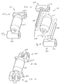
- Fig. 6 is a perspective view of another embodiment of a modular conveying assembly incorporating the present invention.
- Fig. 7 is a partially exploded perspective view of the modular conveying assembly of Fig. 6;
- Fig. 8 is a perspective, exploded view of the cradle shown in Fig. 6;
- Fig. 9 is a perspective, exploded view of another embodiment of a cradle for use in the assembly of Fig. 6;
- Fig. 10 is a perspective, exploded view of yet another embodiment of a cradle for use in the assembly of Fig. 6;
- Fig. 11 is a perspective, exploded view of yet another embodiment of a cradle for use in the assembly of Fig. 6;
- Fig. 12 is a perspective view of yet another embodiment of a cradle for use in the assembly of Fig. 1;
- Fig. 13 is an exploded view of the cradle of Fig. 12;
- Fig. 14 is a perspective, exploded view of yet another embodiment of a cradle for use in the assembly of Fig. 1;
- Fig. 15 is a side elevation view of the cradle of Fig. 10;
- Fig. 16 is a side elevation view of another embodiment of the cradle of Fig. 10 showing the roller extending above and below the cradle;
- Fig. 17 is side elevation view of another embodiment of the cradle of Fig. 10 showing the roller extending below the cradle;
- Fig. 18 is a perspective view of an embodiment of a cradle having an angled shaft for use in a modular conveying assembly
- Fig. 19 is an exploded view of the cradle of Fig. 18;
- Fig. 20 is a perspective view of an embodiment of a cradle having a roller ball for use in a modular conveying assembly
- Fig. 21 is an exploded view of the cradle of Fig. 20.
- a modular conveyor assembly forming a belt 10, shown in Figs. 1 and 2, includes a plurality of chain modules 12 assembled in an edge to edge relation to form the continuous belt 10.
- Hinge pins 14 join adjacent modules 12, and pivotally connect the adjacent modules 12 in the direction of belt travel.
- Cradles 16 retained by the pins 14 between modules 12 in a row support transverse cylindrical rollers 17 that rotatably engage an object being conveyed by the belt 10 to reduce friction between the belt 10 and the object.
- a row of modules 12 is a plurality of the modules 12 disposed between adjacent hinge pins 14.
- the rollers 17 in this embodiment are considered transverse rollers because they have an axis of rotation aligned in the direction of belt travel (indicated by the arrow in Fig. 2) and convey an object transverse to the direction of belt travel.
- the module 12, cradle 16, or roller 17 is damaged, only the damaged component need be replaced.
- the modules 12 are preferably formed using methods known in the art, such as injection molding, from materials known in the art, such as acetal, polyethylene, polypropylene, nylon, and the like.
- Each module 12 includes a body 18 having a top surface 20 surrounded by a leading edge 22 and trailing edge 24 joined by side edges 26.
- the top surface 20 can engage objects being conveyed by the belt 10.
- the module body 18 has a width which is defined by the distance between the side edges 26, and a length which is defined by the distance between the longitudinal leading and trailing edges 22, 24.
- Leading edge hinge members 32 extending forwardly from the leading edge 22 of the module body 18 include coaxial openings 34.
- the opening 34 formed in each leading edge hinge member 32 is coaxial with the opening 34 in the adjacent leading edge hinge member 32 for receiving the hinge pin 14.
- Trailing edge hinge members 36 extending rearwardly from the trailing edge 24 also include coaxial openings 38.
- the opening 38 formed in each trailing edge hinge member 36 is coaxial with the opening in the adjacent trailing edge hinge member 36 of a module 12.
- the forwardly extending leading edge hinge members 32 of one module 12 intermesh with trailing edge hinge members 36 extending rearwardly from an adjacent module 12.
- the openings 34, 38 in the aligned hinge members 32, 36 are aligned to receive the hinge pin 14 which pivotally joins the modules 12 together.
- hinge members 32, 36 extending rearwardly and forwardly from the leading and trailing edges 22, 24, respectively, is shown, the hinge members 32, 36 can also extend in other directions, such as downwardly, proximal the respective edges 22, 24 without departing from the scope of the present invention.
- the cradles 16 are retained by the hinge pins 14, and are not attached directly to the modules 12.
- the cradles 16 are preferably formed using methods known in the art, such as injection molding, from materials known in the art, such as acetal, polyethylene, polypropylene, nylon, and the like.
- the cradles can be formed using other materials, such as metal, without departing from the scope of the invention.
- each cradle 16 has two parallel side walls 40, 42 and two opposing hinge members 44, 46.
- the hinge members 44, 46 define a space, or opening, therebetween that is framed by the hinge members 44, 46 and side walls 40, 42.
- a shaft 48 extending through the opening between the hinge members 44, 46 rotatably supports the roller 17 disposed in the opening.
- the hinge pins 14 pivotally joining the adjacent modules 12 slip into apertures 50, 52 formed through the cradle hinge members 44, 46 that are aligned with the module openings 34, 38 to fix the cradle 16 relative to the adjacent modules 12.
- the position and number of cradles 16 in a belt 10 is customizable, and depends upon the conveyor belt application.
- Each cradle 16 is formed from two separately formed halves 54, 56 to simplify assembly.
- Each half 54, 56 includes one of the side walls 40, 42 having one end 58 joined to one of the hinge members 44, 46.
- the opposing end 60 of each side wall 40, 42 abuts an end of the other hinge member 44, 46, and includes an aperture 62 for receiving the hinge pin 14 extending through the other hinge member 44, 46 joining the adjacent modules 12.
- the shaft 48 extends between the hinge members 44, 46 through the opening, and is substantially parallel and adjacent to the side walls 40, 42 of the assembled cradle 16, such that the shaft is aligned with the direction of belt travel.
- a shaft opening 64 formed in each hinge member 44, 46 opens toward the other hinge member 44, 46 of the assembled cradle 16, and receives one end of the shaft 48.
- the shaft can be formed from any known material, such as plastic, metal, and the like. The shaft material is dependent upon the shaft length and forces that will be exerted upon the shaft 48 in the intended use of the belt 10.
- the shaft 48 is formed from two shaft halves 66, 68.
- Each shaft half 66, 68 extends from one of the hinge members 44, 46, and defines a shaft cross section that is semicircular, such as a half circle, to form the shaft 48 having a circular cross section when the cradle 16 is assembled from the cradle halves 54, 56.
- the half shaft ends can be retained in the hinge member shaft openings 64 using methods known in the art, such as a friction fit, adhesives, and the like, to simplify assembly.
- the shaft 48 is not formed from two halves, such as disclosed in Fig.
- one end of the shaft 48 can be retained in one of the hinge member shaft openings 64, or formed as an integral part of the cradle half 54, to simplify assembly.
- the shaft cannot slip out of the shaft openings 64, and a means for retaining the shaft 48 in only one shaft opening 64 is not necessary, such as shown in Fig. 5.
- the roller 17 is supported by the shaft 48 in the frame opening. At least a portion of the roller 17 extends above the cradle 16 to engage the object being conveyed by the belt 10.
- the roller 17 is molded from a plastic, and includes a throughhole 74 formed therethrough for receiving the shaft 48.
- the roller 17 rotates about the shaft 48 to minimize friction between the belt 10 and object being conveyed.
- the cradle 16 is assembled by slipping the distal ends 70, 72 of each shaft half 66, 68 into opposite ends of the roller throughhole 74.
- the distal ends 70, 72 are then slipped into the opposing hinge member shaft opening 64 such that each end of the shaft 48 is supported by one of the hinge members 44, 46.
- An end of each hinge member 44, 46 of each cradle half 54, 56 abuts a face of the opposing cradle half side wall opposing end 60, such that the hinge member aperture 50, 52 is aligned with the aperture 62 formed in the opposing cradle half side wall opposing end 60.
- a hinge pin 14 joining the adjacent modules 12 is then slipped through the hinge member aperture 50 of one cradle half 54 and the side wall aperture 62 of the other cradle half 56, and another hinge pin 14 is slipped through the hinge member aperture 52 of the other cradle half 56 and the side wall aperture 62 of the one cradle half 54 to prevent the cradle halves 54, 56 from separating.
- a modular conveyor belt 100 includes a cradle 116 supporting a low back pressure roller 117.
- the roller 117 shown in Figs. 6-8 is considered a low back pressure roller because they have an axis of rotation transverse to the direction of belt travel and convey an object in the direction of belt travel.
- the cradle 116 disclosed in Figs. 6-8 is formed from two halves 154, 156. Each half 154, 156 includes a hinge member 144, 146 and a side wall 140, 142, respectively.
- the shaft 148 is formed as an integral part of the side wall 140 of one half 154, and has a distal end 149 that is received in the shaft opening 164 formed in the side wall 142 of the other half 156.
- the shaft 148 can be formed from two half shafts 166, 168, as disclosed in Figs. 9 and 11, and the shaft 148 can be press fit in the shaft openings 164 formed in both side walls 140, 142, as shown in Fig. 10, without departing from the scope of the invention.
- opposing ends 160 of each side wall 140, 142 have a dovetail shape that is received in complementary notches 161 formed in the hinge element 144, 146 forming part of the opposing cradle half 154, 156.
- the dove tailed side wall end 160 interlocks with the notch 161 prevents the cradle halves 154, 156 from separating in the direction of belt travel due to spacing fluctuations between the hinge pins 14 joining the cradle 116 to the modules 12.
- cradles 216, 316 supporting transverse rollers 217, 317 are formed from cradle halves 254, 256, 354, 356 without side walls.
- the cradles 216, 316 include a shaft 248 extending between hinge elements 244, 246, 344, 346.
- the hinge elements 244, 246 include shaft openings 264 for supporting the shaft ends.
- shafts 48 such as disclosed in Figs. 4 and 5 can also be used without departing from the scope of the invention.
- each hinge element 344, 346 includes a pair of meshing eyes 347 for receiving the hinge pins 14.
- cradles including a shaft supporting a roller is positioned to extend a portion of the roller above the cradle (shown in Fig. 15), below the cradle (shown in Fig. 17), or above and below the cradle (shown in Fig. 16).
- a version of the roller cradle 116 shown in Fig. 10 for use in the belt 100 shown in Fig. 6 includes a shaft formed from shaft halves (only shaft half 166 is shown) and defining a shaft axis 176.
- the shaft axis 176 is located above a midpoint 170 between cradle upper and lower edges 172, 174, such that a portion of the roller 117 supported by the shaft extends above the upper edge 172 of the cradle 116.
- a cradle 116 having a portion of the roller 117 extending above the cradle 116, such as shown in Fig. 15, allows an object to move relative to the cradle 116, and thus the belt 100, to minimize back pressure.
- a cradle 116a for use in the belt 100 shown in Fig. 6, includes a shaft formed from shaft halves (only shaft half 166 is shown) and defining a shaft axis 176.
- the shaft axis 176 is located substantially at the midpoint 170 between the cradle upper and lower edges 172, 174 and a roller 117 supported by the shaft has a diameter larger than the distance between the cradle upper and lower edges 172, 174, such that a portion of the roller 117 extends above the roller cradle upper edge 172 and a portion of the roller 117 extends below the cradle lower edge 174.
- an object being conveyed by a belt including the cradles 116a having rollers 117 extending above and below the cradle 116a, such as shown in Fig. 16, can be accelerated in the direction of conveyor travel by engaging the portion of the rollers 117 extending below the cradle lower edge 174 with a surface that rotates the rollers 117 to propel the object supported by the portion of the roller 117 extending above the cradle upper edge 172.
- a cradle 116b for use in the belt 100 shown in Fig. 6, includes a shaft formed from shaft halves (only shaft half 166 is shown) and defining a shaft axis 176.
- the shaft axis 176 is located below the midpoint 170 between the cradle upper and lower edges 172, 174, such that a portion of the roller 117 supported by the shaft extends below the lower edge 174 of the cradle 116b.
- friction between a belt and a supporting surface can be minimized by providing the cradle 116b having a roller 117 extending below the cradle lower edge 174, such as shown in Fig. 17, that engages the supporting surface.
- a roller cradle 416 for use in the belt 10 shown in Fig. 1 and the belt 100 shown in Fig. 6 includes a shaft 448 extending between shaft halves 454, 456 at an angle A defined by the cradle side walls 440, 442 and the shaft 448, such that the shaft 448 is aligned in a direction between the direction of belt travel and the direction transverse to the direction of belt travel.
- the shaft 448 rotatably supports a roller 417 which can support an object being conveyed.
- the angled shaft 448 allows the object to be transferred onto and off of a belt including the cradle 416 at an angle generally corresponding to angle A.
- a cradle 516 for use in the belt 10 shown in Fig. 1 and the belt 100 shown in Fig. 6 supports a spherical roller 517.
- the cradle 516 includes lower and upper shelves 521, 523 extending from each shaft half 554, 556 to rotatably secure the roller 517 between the shaft halves 554, 556.
- the lower shelves 521 extend beneath the ball diameter, and in the embodiment shown in Figs 20 and 21 beneath the roller 517, to support the roller 517.
- the upper shelves 523 extend toward the roller 517 above the ball diameter to secure the roller 517 relative to the lower shelves 521 and allow a portion of the roller 517 to extend above the cradle 516 and support an object being conveyed.
- shelves are preferred, other structure can be provided, such as shafts or other retention member, extending between the cradle halves to rotatably secure the roller relative to the cradle without departing from the scope of the invention.
- the roller 517 and shelves can be sized, such that the roller extends above, below, or above and below the cradle 516 without departing from the scope of the invention.
- both cradle halves include a side wall.
- one cradle halve can be provided without a side wall without departing from the scope of the invention.
- the side walls in the embodiments including side walls engage or abut the opposing hinge member in other embodiments, cradle halves can be provided with side walls that do not touch any part of the other cradle half without departing from the scope of the invention.
Abstract
Description
- The present invention relates to modular conveying assemblies, and more particularly to a modular conveyor belt or chain including roller cradle attachments.
- Modular conveyor belts and chains are formed from interconnected modules that are supported by a frame and driven to transport a product. Each module has a support surface which supports the product as the belting or chain is being driven along the frame. Modules adjacent each other are connected to each other by hinge pins inserted through meshing eyes extending from adjacent links in the direction of the belt travel.
- Modular belts can transport products in the direction of belt travel, but have difficulty transferring a product, especially a high friction product, onto or off of the belt. Moreover, high friction products can easily damage the belt if the product is transferred onto the chain from a direction other than the chain direction of travel. In addition, accumulation of a product on the surface of the chain can easily damage the belt or product being conveyed.
- A conveyor belt formed from roller cradles is disclosed in U.S. Pat No. 4,231,469 issued to Arscott. The cradles support rollers that extend above the cradle for rolling contact with an object being conveyed to reduce friction between the belt and the object. Unfortunately, assembling the roller in the cradle is difficult requiring insertion of the roller into the cradle, and then slipping an axle or two stub axles through holes formed through the cradle walls and into the roller. The axle must then be secured to prevent it from slipping out of one of the holes formed in the cradle wall. A modular conveyor belt in which the modules include a set of rollers is disclosed in US 2001/0045346A.
- The present invention provides a modular conveying assembly for conveying an object. The assembly includes a plurality of chain modules assembled in an edge to edge relation to form a continuous belt. At least one hinge pin joins adjacent chain modules, and pivotally connects the adjacent modules in the direction of belt travel. At least one cradle adjacent at least one of the modules is retained by the at least one pin. A roller is supported by the cradle, is engageable with the object to reduce friction between the belt and the object.
- The cradle includes a first half including a first hinge element. A second half including a second hinge element is spaced from the first hinge element and defines a space therebetween. A shaft extends between the first and second halves through the space defined by the first and second hinge elements. The roller is retained by the shaft in the space for engaging the object.
- A general objective is to provide a modular conveying assembly that can convey high friction objects without severely damaging the objects or the assembly. This objective is accomplished by providing a roller cradle in the assembly that supports a roller that reduces friction between the object and the conveying assembly.
- An objective of the present invention is to provide a cradle that is easy to assemble. This objective is accomplished by forming a cradle from two halves defining a space therebetween and supporting the roller on the space.
- This and still other objectives and advantages of the present invention will be apparent from the description which follows. In the detailed description below, preferred embodiments of the invention will be described in reference to the accompanying drawings. These embodiments do not represent the full scope of the invention. Rather the invention may be employed in other embodiments. Reference should therefore be made to the claims herein for interpreting the breadth of the invention.
- Fig. 1 is a perspective view of a modular conveying assembly incorporating the present invention;
- Fig. 2 is a partially exploded perspective view of the modular conveying assembly of Fig. 1;
- Fig. 3 is a perspective, exploded view of the cradle shown in Fig. 1;
- Fig. 4 is a perspective, exploded view of another embodiment of a cradle for use in the belt of Fig. 1;
- Fig. 5 is a perspective, exploded view of yet another embodiment of a cradle for use in the belt of Fig. 1;
- Fig. 6 is a perspective view of another embodiment of a modular conveying assembly incorporating the present invention;
- Fig. 7 is a partially exploded perspective view of the modular conveying assembly of Fig. 6;
- Fig. 8 is a perspective, exploded view of the cradle shown in Fig. 6;
- Fig. 9 is a perspective, exploded view of another embodiment of a cradle for use in the assembly of Fig. 6;
- Fig. 10 is a perspective, exploded view of yet another embodiment of a cradle for use in the assembly of Fig. 6;
- Fig. 11 is a perspective, exploded view of yet another embodiment of a cradle for use in the assembly of Fig. 6;
- Fig. 12 is a perspective view of yet another embodiment of a cradle for use in the assembly of Fig. 1;
- Fig. 13 is an exploded view of the cradle of Fig. 12;
- Fig. 14 is a perspective, exploded view of yet another embodiment of a cradle for use in the assembly of Fig. 1;
- Fig. 15 is a side elevation view of the cradle of Fig. 10;
- Fig. 16 is a side elevation view of another embodiment of the cradle of Fig. 10 showing the roller extending above and below the cradle;
- Fig. 17 is side elevation view of another embodiment of the cradle of Fig. 10 showing the roller extending below the cradle;
- Fig. 18 is a perspective view of an embodiment of a cradle having an angled shaft for use in a modular conveying assembly;
- Fig. 19 is an exploded view of the cradle of Fig. 18;
- Fig. 20 is a perspective view of an embodiment of a cradle having a roller ball for use in a modular conveying assembly; and
- Fig. 21 is an exploded view of the cradle of Fig. 20.
- A modular conveyor assembly forming a
belt 10, shown in Figs. 1 and 2, includes a plurality ofchain modules 12 assembled in an edge to edge relation to form thecontinuous belt 10. Hingepins 14 joinadjacent modules 12, and pivotally connect theadjacent modules 12 in the direction of belt travel.Cradles 16 retained by thepins 14 betweenmodules 12 in a row support transversecylindrical rollers 17 that rotatably engage an object being conveyed by thebelt 10 to reduce friction between thebelt 10 and the object. A row ofmodules 12 is a plurality of themodules 12 disposed betweenadjacent hinge pins 14. Therollers 17 in this embodiment are considered transverse rollers because they have an axis of rotation aligned in the direction of belt travel (indicated by the arrow in Fig. 2) and convey an object transverse to the direction of belt travel. Advantageously, if themodule 12,cradle 16, orroller 17 is damaged, only the damaged component need be replaced. - The
modules 12 are preferably formed using methods known in the art, such as injection molding, from materials known in the art, such as acetal, polyethylene, polypropylene, nylon, and the like. Eachmodule 12 includes abody 18 having atop surface 20 surrounded by a leadingedge 22 andtrailing edge 24 joined byside edges 26. Advantageously, thetop surface 20 can engage objects being conveyed by thebelt 10. - The
module body 18 has a width which is defined by the distance between theside edges 26, and a length which is defined by the distance between the longitudinal leading andtrailing edges edge hinge members 32 extending forwardly from the leadingedge 22 of themodule body 18 includecoaxial openings 34. Theopening 34 formed in each leadingedge hinge member 32 is coaxial with theopening 34 in the adjacent leadingedge hinge member 32 for receiving thehinge pin 14. Trailingedge hinge members 36 extending rearwardly from the trailingedge 24 also includecoaxial openings 38. As in the leading edgehinge member openings 34, theopening 38 formed in each trailingedge hinge member 36 is coaxial with the opening in the adjacent trailingedge hinge member 36 of amodule 12. - The forwardly extending leading
edge hinge members 32 of onemodule 12 intermesh with trailingedge hinge members 36 extending rearwardly from anadjacent module 12. When theintermeshing hinge members openings hinge members hinge pin 14 which pivotally joins themodules 12 together. Althoughhinge members edges hinge members respective edges - The
cradles 16 are retained by the hinge pins 14, and are not attached directly to themodules 12. Preferably, thecradles 16 are preferably formed using methods known in the art, such as injection molding, from materials known in the art, such as acetal, polyethylene, polypropylene, nylon, and the like. However, the cradles can be formed using other materials, such as metal, without departing from the scope of the invention. - In the embodiments disclosed in Figs. 1-5, each
cradle 16 has twoparallel side walls hinge members hinge members hinge members side walls shaft 48 extending through the opening between thehinge members roller 17 disposed in the opening. The hinge pins 14 pivotally joining theadjacent modules 12 slip intoapertures cradle hinge members module openings cradle 16 relative to theadjacent modules 12. The position and number ofcradles 16 in abelt 10 is customizable, and depends upon the conveyor belt application. - Each
cradle 16 is formed from two separately formedhalves half side walls end 58 joined to one of thehinge members end 60 of eachside wall other hinge member aperture 62 for receiving thehinge pin 14 extending through theother hinge member adjacent modules 12. - The
shaft 48 extends between thehinge members side walls cradle 16, such that the shaft is aligned with the direction of belt travel. Ashaft opening 64 formed in eachhinge member other hinge member cradle 16, and receives one end of theshaft 48. The shaft can be formed from any known material, such as plastic, metal, and the like. The shaft material is dependent upon the shaft length and forces that will be exerted upon theshaft 48 in the intended use of thebelt 10. - In the embodiment disclosed in Figs. 2 and 3, the
shaft 48 is formed from twoshaft halves 66, 68. Eachshaft half 66, 68 extends from one of thehinge members shaft 48 having a circular cross section when thecradle 16 is assembled from the cradle halves 54, 56. The half shaft ends can be retained in the hingemember shaft openings 64 using methods known in the art, such as a friction fit, adhesives, and the like, to simplify assembly. Moreover, if theshaft 48 is not formed from two halves, such as disclosed in Fig. 4, one end of theshaft 48 can be retained in one of the hingemember shaft openings 64, or formed as an integral part of thecradle half 54, to simplify assembly. However, once the cradle halves 54, 56 are assembled together to form thecradle 16, the shaft cannot slip out of theshaft openings 64, and a means for retaining theshaft 48 in only oneshaft opening 64 is not necessary, such as shown in Fig. 5. - Referring back to Figs. 1-3, the
roller 17 is supported by theshaft 48 in the frame opening. At least a portion of theroller 17 extends above thecradle 16 to engage the object being conveyed by thebelt 10. Preferably, theroller 17 is molded from a plastic, and includes a throughhole 74 formed therethrough for receiving theshaft 48. Advantageously, if theroller 17 extends above thecradle 16 to engage an object being conveyed, theroller 17 rotates about theshaft 48 to minimize friction between thebelt 10 and object being conveyed. - The
cradle 16 is assembled by slipping the distal ends 70, 72 of eachshaft half 66, 68 into opposite ends of the roller throughhole 74. The distal ends 70, 72 are then slipped into the opposing hingemember shaft opening 64 such that each end of theshaft 48 is supported by one of thehinge members hinge member cradle half wall opposing end 60, such that thehinge member aperture aperture 62 formed in the opposing cradle half sidewall opposing end 60. Ahinge pin 14 joining theadjacent modules 12 is then slipped through thehinge member aperture 50 of onecradle half 54 and theside wall aperture 62 of theother cradle half 56, and anotherhinge pin 14 is slipped through thehinge member aperture 52 of theother cradle half 56 and theside wall aperture 62 of the onecradle half 54 to prevent the cradle halves 54, 56 from separating. - In another embodiment of the present invention shown in Figs. 6-8, a
modular conveyor belt 100 includes acradle 116 supporting a lowback pressure roller 117. Theroller 117 shown in Figs. 6-8 is considered a low back pressure roller because they have an axis of rotation transverse to the direction of belt travel and convey an object in the direction of belt travel. As in the transverse roller embodiments disclosed in Figs. 1-5, thecradle 116 disclosed in Figs. 6-8 is formed from twohalves half hinge member side wall shaft 148 shown in Figs. 6-8 extends between theside walls back pressure roller 117. Theshaft 148 is formed as an integral part of theside wall 140 of onehalf 154, and has a distal end 149 that is received in theshaft opening 164 formed in theside wall 142 of theother half 156. Of course, theshaft 148 can be formed from twohalf shafts 166, 168, as disclosed in Figs. 9 and 11, and theshaft 148 can be press fit in theshaft openings 164 formed in bothside walls - In the embodiment disclosed in Fig. 11, opposing ends 160 of each
side wall complementary notches 161 formed in thehinge element cradle half side wall end 160 interlocks with thenotch 161 prevents the cradle halves 154, 156 from separating in the direction of belt travel due to spacing fluctuations between the hinge pins 14 joining thecradle 116 to themodules 12. - In yet another embodiment of the present invention shown in Figs. 12-14, cradles 216, 316 supporting
transverse rollers cradle halves cradles 216, 316 include ashaft 248 extending betweenhinge elements hinge elements shaft openings 264 for supporting the shaft ends. Although a shaft formed fromshaft halves shafts 48, such as disclosed in Figs. 4 and 5 can also be used without departing from the scope of the invention. In the embodiment disclosed in Fig. 14, eachhinge element 344, 346 includes a pair of meshingeyes 347 for receiving the hinge pins 14. - In yet other embodiments, shown in Figs. 15-17, cradles including a shaft supporting a roller is positioned to extend a portion of the roller above the cradle (shown in Fig. 15), below the cradle (shown in Fig. 17), or above and below the cradle (shown in Fig. 16). As shown in Fig. 15, a version of the
roller cradle 116 shown in Fig. 10 for use in thebelt 100 shown in Fig. 6, includes a shaft formed from shaft halves (onlyshaft half 166 is shown) and defining ashaft axis 176. Theshaft axis 176 is located above amidpoint 170 between cradle upper andlower edges roller 117 supported by the shaft extends above theupper edge 172 of thecradle 116. Advantageously, acradle 116 having a portion of theroller 117 extending above thecradle 116, such as shown in Fig. 15, allows an object to move relative to thecradle 116, and thus thebelt 100, to minimize back pressure. - In Fig. 16, a cradle 116a for use in the
belt 100 shown in Fig. 6, includes a shaft formed from shaft halves (onlyshaft half 166 is shown) and defining ashaft axis 176. In Fig. 16, theshaft axis 176 is located substantially at themidpoint 170 between the cradle upper andlower edges roller 117 supported by the shaft has a diameter larger than the distance between the cradle upper andlower edges roller 117 extends above the roller cradleupper edge 172 and a portion of theroller 117 extends below the cradlelower edge 174. Advantageously, an object being conveyed by a belt including the cradles 116a havingrollers 117 extending above and below the cradle 116a, such as shown in Fig. 16, can be accelerated in the direction of conveyor travel by engaging the portion of therollers 117 extending below the cradlelower edge 174 with a surface that rotates therollers 117 to propel the object supported by the portion of theroller 117 extending above the cradleupper edge 172. - In Fig. 17, a cradle 116b for use in the
belt 100 shown in Fig. 6, includes a shaft formed from shaft halves (onlyshaft half 166 is shown) and defining ashaft axis 176. In Fig. 17, theshaft axis 176 is located below themidpoint 170 between the cradle upper andlower edges roller 117 supported by the shaft extends below thelower edge 174 of the cradle 116b. Advantageously, friction between a belt and a supporting surface can be minimized by providing the cradle 116b having aroller 117 extending below the cradlelower edge 174, such as shown in Fig. 17, that engages the supporting surface. - In still another embodiment of the present invention shown in Figs. 18 and 19, a
roller cradle 416 for use in thebelt 10 shown in Fig. 1 and thebelt 100 shown in Fig. 6 includes a shaft 448 extending betweenshaft halves 454, 456 at an angle A defined by thecradle side walls 440, 442 and the shaft 448, such that the shaft 448 is aligned in a direction between the direction of belt travel and the direction transverse to the direction of belt travel. The shaft 448 rotatably supports a roller 417 which can support an object being conveyed. The angled shaft 448 allows the object to be transferred onto and off of a belt including thecradle 416 at an angle generally corresponding to angle A. - In yet another embodiment shown in Figs. 20 and 21, a
cradle 516 for use in thebelt 10 shown in Fig. 1 and thebelt 100 shown in Fig. 6 supports aspherical roller 517. Thecradle 516 includes lower andupper shelves 521, 523 extending from each shaft half 554, 556 to rotatably secure theroller 517 between the shaft halves 554, 556. The lower shelves 521 extend beneath the ball diameter, and in the embodiment shown in Figs 20 and 21 beneath theroller 517, to support theroller 517. Theupper shelves 523 extend toward theroller 517 above the ball diameter to secure theroller 517 relative to the lower shelves 521 and allow a portion of theroller 517 to extend above thecradle 516 and support an object being conveyed. Although shelves are preferred, other structure can be provided, such as shafts or other retention member, extending between the cradle halves to rotatably secure the roller relative to the cradle without departing from the scope of the invention. Moreover, theroller 517 and shelves can be sized, such that the roller extends above, below, or above and below thecradle 516 without departing from the scope of the invention. - While there has been shown and described what are at present considered the preferred embodiments of the invention, it will be obvious to those skilled in the art that various changes and modifications can be made therein without departing from the scope of the invention defined by the appended claims. For example, in the embodiments disclosed in Figs. 1-5, both cradle halves include a side wall. However, one cradle halve can be provided without a side wall without departing from the scope of the invention. In addition, the side walls in the embodiments including side walls engage or abut the opposing hinge member, in other embodiments, cradle halves can be provided with side walls that do not touch any part of the other cradle half without departing from the scope of the invention.
Claims (32)
- A roller cradle for use in a modular conveying assembly having a direction of travel in which an object is conveyed, said cradle (16) comprising:a first half including a first binge el ement (44);a second half formed separately from said first half and including a second hinge element (46) spaced from said first hinge element (44) and defining a space therebetween; anda roller (17) retained in said space.
- The roller cradle as in claim 1, in which a shaft (48) extends between said first and second halves through said space, and said shaft (48) retains said roller (17) in said space.
- The roller cradle as in claim 1, in which said shaft (48) is aligned in a direction selected from a group consisting of the direction of travel, transverse to the direction of travel, and at an acute angle between the direction of travel and transverse to the direction of travel.
- The roller cradle as in claim 2, in which said shaft (48) extends through said roller (17) to rotatably mount said roller (17) in said space.
- The roller cradle as in claim 2, in which each of said hinge elements include a shaft aperture (64) that receives one end of said shaft (48).
- The roller cradle as in claim 2, in which said shaft (48) is formed from two shaft halves (66,68), and each shaft half has a semicircular cross section.
- The roller cradle as in claim 2, in which said shaft (48) extends between said first and second hinge elements (44,46) through said space.
- The roller cradle as in claim 1, including a first cradle side wall (42) having first and second ends (58,60), said first end (58) being joined to one of said hinge elements (46), and said second end (60) extending toward the other of said binge elements (46).
- The roller cradle as in claim 8, in which said second end (60) abuts an end of said other of said hinge elements (44).
- The roller cradle as in claim 8, in which said second end (60) interlocks with said other of said hinge elements (44).
- The roller cradle as in claim 8, including a second cradle side wall (40) having a first end and a second end (58), said first end of said second cradle side wall being joined to said other of said hinge elements (46), and said second end (60) of said second cradle side wall (40) extending toward said one of said hinge element to frame said space between said hinge elements (44,46).
- The roller cradle as in claim 11, in which a shaft (48) extends through said space between said first and second side walls (40,42), and said shaft retains said roller (17) in said space.
- The roller cradle as in claim 8, in which said first cradle side wall (42) and said one of said hinge elements (46) are formed as an integral piece.
- The roller cradle as in claim 1, in which at least one of said hinge elements (44,46) includes more than one meshing eye.
- The roller cradle as in claim 1, in which at least a portion of said roller (17) extends at least one of above said cradle (16) and below said cradle (16).
- The roller cradle as in claim 1, in which said roller (17) has a shape selected from a group consisting of spherical and cylindrical.
- A modular conveying assembly for conveying an object in a direction of travel, said assembly comprising:a plurality of chain modules (12) assembled in an edge to edge relation to form a continuous belt (10);at least one hinge pin (14) joining adjacent chain modules, and pivotally connecting the adjacent modules in the direction of belt travel;at least one cradle (16) adjacent at least one of said modules (12) is retained by said at least one pin (14), said cradle (16) having an upper edge and a lower edgea roller (17) supported by said cradle (16) and extending beyond at least one of said edges;in which said cradle (16) includes:a first half including a first hinge element (44); anda second half formed separately from said first half and including a second binge clement (46) spaced from said first hinge element (44) and defining a space therebetween.
- The modular conveying assembly as in claim 17, in which a shaft (48) extends between said first and second halves through said space, and said shaft (48) retains said roller (17) in said space.
- The modular conveying assembly as in claim 18, in which said shaft (48) is aligned in a direction selected from a group consisting of the direction of conveyor travel, transverse to the direction of conveyor travel, and at an acute angle between the direction of conveyor travel and transverse to the direction of conveyor travel.
- The modular conveying assembly as in claim 18, in which said shaft (48) extends through said roller (17) to rotatably mount said roller (17) in said space.
- The modular conveying assembly as in claim 18, in which each of said hinge elements include a shaft aperture (64) that receives one end of said shaft (48).
- The modular conveying assembly as in claim 18, in which said shaft (48) is formed from two shaft halves (66,68), and each shaft half has a semicircular cross section.
- The modular conveying assembly as in claim 18, in which said shaft (48) extends between said first and second hinge elements (44,46) through said space.
- The modular conveying assembly as in claim 17, including a first cradle side wall (42) having first and second ends (58,60), said first end (58) being joined to one of said hinge elements (46), and said second end (60) extending toward the other of said hinge elements (46).
- The modular conveying assembly as in claim 24, in which said second end (60) abuts an end of said other of said hinge elements (44).
- The modular conveying assembly as in claim 24, in which said second end (60) interlocks with said other of said hinge elements (44).
- The modular conveying assembly as in claim 24, including a second cradle side wall (40) having a first end and a second end, said first end (58) of said second cradle side wall being joined to said other of said hinge elements (46), and said second end (60) of said second cradle side wall (40) extending toward said one of said hinge element to frame said space between said hinge elements (44,46).
- The modular conveying assembly as in claim 27, in which a shaft (48) extends through said space between said first and second side walls (40,42), and said shaft retains said roller (17) in said space.
- The modular conveying assembly as in claim 24, in which said first cradle side wall (42) and said one of said hinge elements (46) are formed as an integral piece.
- The modular conveying assembly as in claim 17, in which at least one of said hinge elements (44,46) includes more than one meshing eye.
- The modular conveying assembly as in claim 17, in which at least a portion of said roller (17) extends at least one of above said cradle (16) and below said cradle (16).
- The modular conveying assembly as in claim 17, in which said roller (17) has a shape selected from a group consisting of spherical and cylindrical.
Applications Claiming Priority (5)
| Application Number | Priority Date | Filing Date | Title |
|---|---|---|---|
| US45152003P | 2003-03-03 | 2003-03-03 | |
| US451520P | 2003-03-03 | ||
| US52953903P | 2003-12-15 | 2003-12-15 | |
| US529539P | 2003-12-15 | ||
| PCT/US2004/006296 WO2004078619A1 (en) | 2003-03-03 | 2004-03-02 | Modular conveying assembly having roller cradles |
Publications (2)
| Publication Number | Publication Date |
|---|---|
| EP1599397A1 EP1599397A1 (en) | 2005-11-30 |
| EP1599397B1 true EP1599397B1 (en) | 2006-07-26 |
Family
ID=32965555
Family Applications (2)
| Application Number | Title | Priority Date | Filing Date |
|---|---|---|---|
| EP04716412A Expired - Lifetime EP1599398B1 (en) | 2003-03-03 | 2004-03-02 | Roller cradle and modular conveying assembly with a roller cradle |
| EP04716446A Expired - Lifetime EP1599397B1 (en) | 2003-03-03 | 2004-03-02 | Modular conveying assembly having roller cradles |
Family Applications Before (1)
| Application Number | Title | Priority Date | Filing Date |
|---|---|---|---|
| EP04716412A Expired - Lifetime EP1599398B1 (en) | 2003-03-03 | 2004-03-02 | Roller cradle and modular conveying assembly with a roller cradle |
Country Status (12)
| Country | Link |
|---|---|
| US (3) | US6997309B2 (en) |
| EP (2) | EP1599398B1 (en) |
| JP (2) | JP4564001B2 (en) |
| KR (2) | KR20050113629A (en) |
| AT (2) | ATE373615T1 (en) |
| BR (2) | BRPI0408016B1 (en) |
| CA (2) | CA2517685C (en) |
| DE (2) | DE602004001674T2 (en) |
| DK (2) | DK1599397T3 (en) |
| ES (2) | ES2270354T3 (en) |
| MX (2) | MXPA05009355A (en) |
| WO (2) | WO2004078619A1 (en) |
Families Citing this family (43)
| Publication number | Priority date | Publication date | Assignee | Title |
|---|---|---|---|---|
| US6997309B2 (en) * | 2003-03-03 | 2006-02-14 | Rexnord Industries, Inc. | Roller cradle and modular conveying assembly formed therefrom |
| JP3954040B2 (en) * | 2004-04-28 | 2007-08-08 | 株式会社椿本チエイン | Conveyor chain |
| DE102004021262A1 (en) * | 2004-04-30 | 2005-11-17 | Sander Hansen A/S | Pasteur with conveyor |
| JP3930007B2 (en) | 2004-09-03 | 2007-06-13 | 株式会社椿本チエイン | Conveyor chain |
| JP3949685B2 (en) * | 2004-12-24 | 2007-07-25 | 株式会社椿本チエイン | Multi-function conveyor chain |
| MX2007008120A (en) * | 2005-01-03 | 2007-09-11 | Laitram Llc | Conveyor having a conveyor belt with flights, including segmented flights for gapless end transfer. |
| KR200390957Y1 (en) * | 2005-05-10 | 2005-07-28 | 명화기계(주) | chain - conveyer of having change direct roller |
| JP4173151B2 (en) * | 2005-05-23 | 2008-10-29 | 株式会社椿本チエイン | Conveyor chain |
| DE102005023859B4 (en) † | 2005-05-24 | 2007-04-19 | Schaefer Förderanlagen- und Maschinenbau GmbH | Grouping table for merging containers |
| ITTV20050120A1 (en) * | 2005-08-12 | 2007-02-13 | Plastomeccanica Spa | CONVEYOR CHAIN MESH |
| MX2008002464A (en) * | 2005-09-02 | 2008-04-03 | Span Tech Llc | Wear-resistant connector for a modular link conveyor belt. |
| DK177219B1 (en) | 2005-09-20 | 2012-07-09 | Ammeraal Beltech Modular As | Conveyor belt module including one or more rollers |
| US20070257427A1 (en) * | 2005-12-16 | 2007-11-08 | Ncr Corporation | Stacker wheel |
| US7461739B2 (en) * | 2006-01-26 | 2008-12-09 | Laitram, L.L.C. | Systems and methods for diverting objects |
| US7886892B2 (en) * | 2006-01-26 | 2011-02-15 | Laitram, L.L.C. | Conveyor belt having rollers as tensile members |
| JP2009532308A (en) * | 2006-04-03 | 2009-09-10 | スパン テック エルエルシー | Product conveying component with powder coating and method related thereto |
| US7997404B2 (en) * | 2006-11-03 | 2011-08-16 | Habasit Ag | Conveyor belt with intermodular supported spheres |
| US7527143B2 (en) * | 2006-11-03 | 2009-05-05 | Habasit Ag | Conveyor belt with intermodular supported rollers |
| US7360641B1 (en) * | 2007-04-13 | 2008-04-22 | Laitram, L.L.C. | Conveyor belt having rollers that displace objects |
| US7540368B2 (en) * | 2007-05-01 | 2009-06-02 | Laitram, L.L.C. | Transverse-roller belts and modules |
| US7556136B2 (en) | 2007-10-11 | 2009-07-07 | Laitram, L.L.C. | Conveyor belt module with retained rollers |
| US7533766B1 (en) * | 2008-01-23 | 2009-05-19 | Laitram, L.L.C. | Apparatus and method for activating conveyor belt rollers |
| US7891481B2 (en) * | 2008-09-11 | 2011-02-22 | Laitram, L.L.C. | Conveyor belt for mounting oblique rollers on lateral rods |
| US8172069B2 (en) * | 2009-03-26 | 2012-05-08 | Habasit Ag | Diverter ball conveyor |
| US7861849B2 (en) * | 2009-04-02 | 2011-01-04 | Laitram, L.L.C. | Merge conveyor including high-friction rollers |
| US8167118B2 (en) * | 2009-09-10 | 2012-05-01 | Laitram, L.L.C. | Conveyors, belts, and modules with actuated rollers |
| US8579104B2 (en) * | 2010-05-13 | 2013-11-12 | Laitram, L.L.C. | Conveyor belt and module accommodating rod growth |
| DE202010009325U1 (en) * | 2010-06-21 | 2011-08-17 | Krones Ag | conveyor belt |
| EP2500495B1 (en) * | 2011-03-14 | 2014-05-07 | K. Hartwall Oy AB | Hinge module, hinge assembly and roll container |
| US8496105B2 (en) * | 2011-05-23 | 2013-07-30 | Laitram, L.L.C. | Roller-top belt with beam stiffness |
| US8474602B2 (en) | 2011-05-23 | 2013-07-02 | Laitram | Multi-piece conveyor belt rollers |
| US8646595B2 (en) | 2011-05-23 | 2014-02-11 | Laitram, L.L.C. | Snap-on conveyor belt rollers |
| US8881890B2 (en) * | 2011-05-23 | 2014-11-11 | Laitram, L.L.C. | Conveyor belt module with fixed axles |
| US10343851B2 (en) | 2015-08-05 | 2019-07-09 | Laitram, L.L.C. | Article diverting conveyor belt |
| CN107265619A (en) * | 2016-04-06 | 2017-10-20 | 世奇综合环境株式会社 | Utilize the quality purifying device for water of solar power generation |
| WO2018062992A1 (en) * | 2016-09-30 | 2018-04-05 | Jonge Poerink Conveyors B.V. | Filling element and complementary link for a conveyor chain, conveyor chain and method of assembly thereof |
| WO2018165489A1 (en) | 2017-03-08 | 2018-09-13 | Advanced Technology & Research Corp. | Package sorting transfer module and systems and methods therefor |
| US10532894B2 (en) | 2017-03-10 | 2020-01-14 | Regal Beloit America, Inc. | Modular transfer units, systems, and methods |
| US10640303B2 (en) | 2017-11-22 | 2020-05-05 | Regal Beloit America, Inc. | Modular sortation units, systems, and methods |
| IT201800002943A1 (en) * | 2018-02-22 | 2019-08-22 | Plastorgomma Srl | SYSTEM FOR THE TRANSPORT AND HANDLING OF OBJECTS |
| CN113573992B (en) * | 2019-04-22 | 2023-09-15 | 莱特拉姆有限责任公司 | Modular nose roller assembly for conveyor |
| USD956834S1 (en) * | 2021-01-19 | 2022-07-05 | Edward O'Hanrahan, Jr. | Forged roller assembly |
| USD957483S1 (en) * | 2021-01-19 | 2022-07-12 | Edward O'Hanrahan, Jr. | Forged roller assembly |
Family Cites Families (36)
| Publication number | Priority date | Publication date | Assignee | Title |
|---|---|---|---|---|
| US1377450A (en) | 1919-09-08 | 1921-05-10 | Charles N Whipple | Drag-chain link |
| US1641642A (en) | 1926-08-05 | 1927-09-06 | A P H Hudson | Conveyer chain |
| US2554038A (en) * | 1948-05-12 | 1951-05-22 | Jeffrey Mfg Co | Chain having rollers forming its conveying surface |
| US2987167A (en) * | 1957-10-10 | 1961-06-06 | Ruth R Young | Belt conveyor structures |
| US3082861A (en) | 1959-09-29 | 1963-03-26 | Andrew T Kornylak | Conveyor belt |
| US3964588A (en) * | 1967-09-13 | 1976-06-22 | Kornylak Corporation | Conveyor having provision for discharging loads at an angle generally transverse to the line of travel or the conveyor |
| US3550756A (en) * | 1967-09-13 | 1970-12-29 | Kornylac Co | Conveyor having provision for discharging loads at an angle generally transverse to the line of travel on the conveyor |
| GB1598891A (en) * | 1978-01-20 | 1981-09-23 | Ling Systems Ltd | Travelling conveyor having article contacting rollers |
| US5096050A (en) * | 1981-06-02 | 1992-03-17 | Rexnord Corporation | Low backline pressure chain |
| US5330045A (en) | 1981-06-02 | 1994-07-19 | Rexnord Corporation | Low backline pressure chain |
| EP0152639B1 (en) * | 1982-02-22 | 1988-02-10 | Rexnord Inc. | Low backline pressure chain |
| USD289734S (en) | 1985-01-11 | 1987-05-12 | Rexnord Inc. | Conveyor chain link |
| USD299424S (en) | 1985-06-17 | 1989-01-17 | Rexnord Inc. | Chain link |
| USD299425S (en) | 1985-06-17 | 1989-01-17 | Rexnord Inc. | Chain link |
| NL8600734A (en) * | 1986-03-21 | 1987-10-16 | Capelleveen Bv Geb | TRANSPORTER. |
| US4880107A (en) * | 1987-07-31 | 1989-11-14 | Rexnord Corporation | Table top chain link with rib |
| US4925016A (en) * | 1987-10-06 | 1990-05-15 | The Laitram Corporation | Heavy duty modular conveyor belt and sprocket with unique tracking |
| US4821869A (en) | 1987-11-23 | 1989-04-18 | Rexnord Inc. | Low backline pressure chain for use with transfer plate |
| US5224583A (en) | 1990-10-09 | 1993-07-06 | Palmaer K V | Low back pressure plastic conveyor |
| IT222736Z2 (en) | 1991-09-19 | 1995-04-24 | Regina Sud Spa | CONTINUOUS ROLLER CONVEYOR |
| DE4140206A1 (en) | 1991-12-05 | 1993-06-09 | Johann A. Krause Maschinenfabrik Gmbh, 2820 Bremen, De | DEVICE FOR TRANSPORTING OBJECTS |
| US5238099A (en) | 1992-08-04 | 1993-08-24 | Premark Feg Corporation | Conveying system |
| US5706934A (en) | 1994-11-14 | 1998-01-13 | Kvp Systems, Inc. | Modular solid top plastic conveyor belt |
| US6315109B1 (en) * | 1998-04-30 | 2001-11-13 | Stewart & Stephenson Services, Inc. | Split roller wheel and method of assembly |
| US6044956A (en) | 1998-07-01 | 2000-04-04 | Fki Industries, Inc. | Sortation conveyor system for high friction articles |
| US6148990A (en) * | 1998-11-02 | 2000-11-21 | The Laitram Corporation | Modular roller-top conveyor belt |
| US6494312B2 (en) | 1998-11-02 | 2002-12-17 | The Laitram Corporation | Modular roller-top conveyor belt with obliquely-arranged rollers |
| US6161685A (en) * | 1999-03-26 | 2000-12-19 | Rexnord Corporation | Thermoplastic chain link for a modular conveyor chain |
| US6257397B1 (en) * | 1999-09-23 | 2001-07-10 | Sasib North America, Inc. | Conveyor for continuous proofing and baking apparatus |
| US6364095B1 (en) * | 2000-04-13 | 2002-04-02 | Span Tech Llc | Modular conveyor system with side flexing belt having roller support |
| US6398015B1 (en) | 2000-05-03 | 2002-06-04 | The Laitram Corporation | Roller-top conveyor belt and modules with closely-spaced rollers |
| US6604625B2 (en) * | 2001-10-31 | 2003-08-12 | The Laitram Corporation | Operating modular conveyor belts with migrating hinge pins |
| US6997309B2 (en) * | 2003-03-03 | 2006-02-14 | Rexnord Industries, Inc. | Roller cradle and modular conveying assembly formed therefrom |
| EP1477434B1 (en) * | 2003-05-06 | 2004-11-24 | Costruzioni Meccaniche Crizaf S.p.A. | Modular belt having transverse conveying members |
| US6932211B2 (en) * | 2003-12-15 | 2005-08-23 | Rexnord Industries, Inc. | Modular conveying assembly with stub mounted in-line rollers |
| US7168557B2 (en) * | 2004-12-06 | 2007-01-30 | Rexnord Industries, Llc | Side-flexing conveyor chain having members joined by linkages |
-
2004
- 2004-03-01 US US10/790,485 patent/US6997309B2/en not_active Expired - Lifetime
- 2004-03-01 US US10/790,486 patent/US7246700B2/en not_active Expired - Lifetime
- 2004-03-02 ES ES04716446T patent/ES2270354T3/en not_active Expired - Lifetime
- 2004-03-02 WO PCT/US2004/006296 patent/WO2004078619A1/en active IP Right Grant
- 2004-03-02 BR BRPI0408016A patent/BRPI0408016B1/en active IP Right Grant
- 2004-03-02 KR KR1020057016381A patent/KR20050113629A/en not_active Application Discontinuation
- 2004-03-02 DE DE602004001674T patent/DE602004001674T2/en not_active Expired - Lifetime
- 2004-03-02 JP JP2006508982A patent/JP4564001B2/en not_active Expired - Lifetime
- 2004-03-02 MX MXPA05009355A patent/MXPA05009355A/en active IP Right Grant
- 2004-03-02 WO PCT/US2004/006151 patent/WO2004078621A1/en active IP Right Grant
- 2004-03-02 AT AT04716412T patent/ATE373615T1/en not_active IP Right Cessation
- 2004-03-02 KR KR1020057016383A patent/KR20050113630A/en not_active Application Discontinuation
- 2004-03-02 JP JP2006508939A patent/JP4592686B2/en not_active Expired - Lifetime
- 2004-03-02 AT AT04716446T patent/ATE334086T1/en not_active IP Right Cessation
- 2004-03-02 MX MXPA05009354A patent/MXPA05009354A/en active IP Right Grant
- 2004-03-02 CA CA2517685A patent/CA2517685C/en not_active Expired - Lifetime
- 2004-03-02 BR BRPI0408030A patent/BRPI0408030B1/en active IP Right Grant
- 2004-03-02 EP EP04716412A patent/EP1599398B1/en not_active Expired - Lifetime
- 2004-03-02 DE DE602004009044T patent/DE602004009044T2/en not_active Expired - Lifetime
- 2004-03-02 EP EP04716446A patent/EP1599397B1/en not_active Expired - Lifetime
- 2004-03-02 CA CA2517677A patent/CA2517677C/en not_active Expired - Lifetime
- 2004-03-02 ES ES04716412T patent/ES2294478T3/en not_active Expired - Lifetime
- 2004-03-02 DK DK04716446T patent/DK1599397T3/en active
- 2004-03-02 DK DK04716412T patent/DK1599398T3/en active
-
2007
- 2007-05-29 US US11/754,729 patent/US7331448B2/en not_active Expired - Lifetime
Also Published As
Similar Documents
| Publication | Publication Date | Title |
|---|---|---|
| EP1599397B1 (en) | Modular conveying assembly having roller cradles | |
| US7527146B2 (en) | Conveyor module with a snap fit extension for supporting a roller | |
| EP1616818B1 (en) | Split rollers conveyor module | |
| CA2549005C (en) | Modular conveying assembly with stub mounted in-line rollers | |
| CA2525208C (en) | Low backline pressure modular conveying assembly | |
| CA2889025A1 (en) | Active control roller top modular conveying assembly |
Legal Events
| Date | Code | Title | Description |
|---|---|---|---|
| PUAI | Public reference made under article 153(3) epc to a published international application that has entered the european phase |
Free format text: ORIGINAL CODE: 0009012 |
|
| 17P | Request for examination filed |
Effective date: 20050902 |
|
| AK | Designated contracting states |
Kind code of ref document: A1 Designated state(s): AT BE BG CH CY CZ DE DK EE ES FI FR GB GR HU IE IT LI LU MC NL PL PT RO SE SI SK TR |
|
| AX | Request for extension of the european patent |
Extension state: AL LT LV MK |
|
| RIN1 | Information on inventor provided before grant (corrected) |
Inventor name: HANSEN, KEVIN, S. Inventor name: WIETING, DEAN, A. Inventor name: STEBNICKI, JAMES, C. |
|
| GRAP | Despatch of communication of intention to grant a patent |
Free format text: ORIGINAL CODE: EPIDOSNIGR1 |
|
| GRAS | Grant fee paid |
Free format text: ORIGINAL CODE: EPIDOSNIGR3 |
|
| DAX | Request for extension of the european patent (deleted) | ||
| GRAA | (expected) grant |
Free format text: ORIGINAL CODE: 0009210 |
|
| AK | Designated contracting states |
Kind code of ref document: B1 Designated state(s): AT BE BG CH CY CZ DE DK EE ES FI FR GB GR HU IE IT LI LU MC NL PL PT RO SE SI SK TR |
|
| PG25 | Lapsed in a contracting state [announced via postgrant information from national office to epo] |
Ref country code: SK Free format text: LAPSE BECAUSE OF FAILURE TO SUBMIT A TRANSLATION OF THE DESCRIPTION OR TO PAY THE FEE WITHIN THE PRESCRIBED TIME-LIMIT Effective date: 20060726 Ref country code: SI Free format text: LAPSE BECAUSE OF FAILURE TO SUBMIT A TRANSLATION OF THE DESCRIPTION OR TO PAY THE FEE WITHIN THE PRESCRIBED TIME-LIMIT Effective date: 20060726 Ref country code: RO Free format text: LAPSE BECAUSE OF FAILURE TO SUBMIT A TRANSLATION OF THE DESCRIPTION OR TO PAY THE FEE WITHIN THE PRESCRIBED TIME-LIMIT Effective date: 20060726 Ref country code: PL Free format text: LAPSE BECAUSE OF FAILURE TO SUBMIT A TRANSLATION OF THE DESCRIPTION OR TO PAY THE FEE WITHIN THE PRESCRIBED TIME-LIMIT Effective date: 20060726 Ref country code: IT Free format text: LAPSE BECAUSE OF FAILURE TO SUBMIT A TRANSLATION OF THE DESCRIPTION OR TO PAY THE FEE WITHIN THE PRESCRIBED TIME-LIMIT;WARNING: LAPSES OF ITALIAN PATENTS WITH EFFECTIVE DATE BEFORE 2007 MAY HAVE OCCURRED AT ANY TIME BEFORE 2007. THE CORRECT EFFECTIVE DATE MAY BE DIFFERENT FROM THE ONE RECORDED. Effective date: 20060726 Ref country code: CZ Free format text: LAPSE BECAUSE OF FAILURE TO SUBMIT A TRANSLATION OF THE DESCRIPTION OR TO PAY THE FEE WITHIN THE PRESCRIBED TIME-LIMIT Effective date: 20060726 Ref country code: BE Free format text: LAPSE BECAUSE OF FAILURE TO SUBMIT A TRANSLATION OF THE DESCRIPTION OR TO PAY THE FEE WITHIN THE PRESCRIBED TIME-LIMIT Effective date: 20060726 Ref country code: AT Free format text: LAPSE BECAUSE OF FAILURE TO SUBMIT A TRANSLATION OF THE DESCRIPTION OR TO PAY THE FEE WITHIN THE PRESCRIBED TIME-LIMIT Effective date: 20060726 |
|
| REG | Reference to a national code |
Ref country code: GB Ref legal event code: FG4D |
|
| REG | Reference to a national code |
Ref country code: CH Ref legal event code: EP |
|
| REG | Reference to a national code |
Ref country code: IE Ref legal event code: FG4D |
|
| REF | Corresponds to: |
Ref document number: 602004001674 Country of ref document: DE Date of ref document: 20060907 Kind code of ref document: P |
|
| PG25 | Lapsed in a contracting state [announced via postgrant information from national office to epo] |
Ref country code: BG Free format text: LAPSE BECAUSE OF FAILURE TO SUBMIT A TRANSLATION OF THE DESCRIPTION OR TO PAY THE FEE WITHIN THE PRESCRIBED TIME-LIMIT Effective date: 20061026 |
|
| REG | Reference to a national code |
Ref country code: SE Ref legal event code: TRGR |
|
| REG | Reference to a national code |
Ref country code: DK Ref legal event code: T3 |
|
| REG | Reference to a national code |
Ref country code: CH Ref legal event code: NV Representative=s name: R. A. EGLI & CO. PATENTANWAELTE |
|
| PG25 | Lapsed in a contracting state [announced via postgrant information from national office to epo] |
Ref country code: PT Free format text: LAPSE BECAUSE OF FAILURE TO SUBMIT A TRANSLATION OF THE DESCRIPTION OR TO PAY THE FEE WITHIN THE PRESCRIBED TIME-LIMIT Effective date: 20061226 |
|
| ET | Fr: translation filed | ||
| REG | Reference to a national code |
Ref country code: ES Ref legal event code: FG2A Ref document number: 2270354 Country of ref document: ES Kind code of ref document: T3 |
|
| PLBE | No opposition filed within time limit |
Free format text: ORIGINAL CODE: 0009261 |
|
| STAA | Information on the status of an ep patent application or granted ep patent |
Free format text: STATUS: NO OPPOSITION FILED WITHIN TIME LIMIT |
|
| 26N | No opposition filed |
Effective date: 20070427 |
|
| PG25 | Lapsed in a contracting state [announced via postgrant information from national office to epo] |
Ref country code: MC Free format text: LAPSE BECAUSE OF NON-PAYMENT OF DUE FEES Effective date: 20070331 Ref country code: IE Free format text: LAPSE BECAUSE OF NON-PAYMENT OF DUE FEES Effective date: 20070302 |
|
| PG25 | Lapsed in a contracting state [announced via postgrant information from national office to epo] |
Ref country code: GR Free format text: LAPSE BECAUSE OF FAILURE TO SUBMIT A TRANSLATION OF THE DESCRIPTION OR TO PAY THE FEE WITHIN THE PRESCRIBED TIME-LIMIT Effective date: 20061027 |
|
| PG25 | Lapsed in a contracting state [announced via postgrant information from national office to epo] |
Ref country code: EE Free format text: LAPSE BECAUSE OF FAILURE TO SUBMIT A TRANSLATION OF THE DESCRIPTION OR TO PAY THE FEE WITHIN THE PRESCRIBED TIME-LIMIT Effective date: 20060726 |
|
| PG25 | Lapsed in a contracting state [announced via postgrant information from national office to epo] |
Ref country code: LU Free format text: LAPSE BECAUSE OF NON-PAYMENT OF DUE FEES Effective date: 20070302 Ref country code: CY Free format text: LAPSE BECAUSE OF FAILURE TO SUBMIT A TRANSLATION OF THE DESCRIPTION OR TO PAY THE FEE WITHIN THE PRESCRIBED TIME-LIMIT Effective date: 20060726 |
|
| PG25 | Lapsed in a contracting state [announced via postgrant information from national office to epo] |
Ref country code: TR Free format text: LAPSE BECAUSE OF FAILURE TO SUBMIT A TRANSLATION OF THE DESCRIPTION OR TO PAY THE FEE WITHIN THE PRESCRIBED TIME-LIMIT Effective date: 20060726 Ref country code: HU Free format text: LAPSE BECAUSE OF FAILURE TO SUBMIT A TRANSLATION OF THE DESCRIPTION OR TO PAY THE FEE WITHIN THE PRESCRIBED TIME-LIMIT Effective date: 20070127 |
|
| REG | Reference to a national code |
Ref country code: FR Ref legal event code: PLFP Year of fee payment: 13 |
|
| REG | Reference to a national code |
Ref country code: FR Ref legal event code: PLFP Year of fee payment: 14 |
|
| REG | Reference to a national code |
Ref country code: FR Ref legal event code: PLFP Year of fee payment: 15 |
|
| REG | Reference to a national code |
Ref country code: DE Ref legal event code: R081 Ref document number: 602004001674 Country of ref document: DE Owner name: REXNORD INDUSTRIES, LLC, MILWAUKEE, US Free format text: FORMER OWNER: REXNORD CORP., MILWAUKEE, WIS., US Ref country code: DE Ref legal event code: R082 Ref document number: 602004001674 Country of ref document: DE Representative=s name: VEREENIGDE OCTROOIBUREAUX N.V., DE |
|
| PGFP | Annual fee paid to national office [announced via postgrant information from national office to epo] |
Ref country code: FR Payment date: 20230328 Year of fee payment: 20 Ref country code: FI Payment date: 20230327 Year of fee payment: 20 Ref country code: DK Payment date: 20230329 Year of fee payment: 20 |
|
| PGFP | Annual fee paid to national office [announced via postgrant information from national office to epo] |
Ref country code: SE Payment date: 20230315 Year of fee payment: 20 Ref country code: IT Payment date: 20230321 Year of fee payment: 20 Ref country code: GB Payment date: 20230327 Year of fee payment: 20 Ref country code: DE Payment date: 20230329 Year of fee payment: 20 |
|
| PGFP | Annual fee paid to national office [announced via postgrant information from national office to epo] |
Ref country code: NL Payment date: 20230326 Year of fee payment: 20 |
|
| PGFP | Annual fee paid to national office [announced via postgrant information from national office to epo] |
Ref country code: ES Payment date: 20230403 Year of fee payment: 20 Ref country code: CH Payment date: 20230402 Year of fee payment: 20 |
|
| P01 | Opt-out of the competence of the unified patent court (upc) registered |
Effective date: 20240111 |
|
| REG | Reference to a national code |
Ref country code: DE Ref legal event code: R071 Ref document number: 602004001674 Country of ref document: DE |
|
| REG | Reference to a national code |
Ref country code: DK Ref legal event code: EUP Expiry date: 20240302 |
|
| REG | Reference to a national code |
Ref country code: NL Ref legal event code: MK Effective date: 20240301 |
|
| REG | Reference to a national code |
Ref country code: CH Ref legal event code: PL |
|
| REG | Reference to a national code |
Ref country code: ES Ref legal event code: FD2A Effective date: 20240326 |
|
| REG | Reference to a national code |
Ref country code: GB Ref legal event code: PE20 Expiry date: 20240301 |