-
The present invention relates to a wireless
communication apparatus which performs media access
control and, more particularly, to access control for
improving Quality of Service (QoS).
-
MAC (Media Access Control) is control for causing
a plurality of communication apparatuses which perform
communication while sharing the same medium to decide
how to use the medium in transmitting communication
data. Owing to media access control, even if two or
more communication apparatuses transmit communication
data by using the same medium at the same time, there
is less chance of the occurrence of a phenomenon
(collision) in which a communication apparatus on the
receiving side cannot decode communication data. Media
access control is also a technique for controlling
access from communication apparatuses to a medium so
as to minimize the chance of the occurrence of a
phenomenon in which, despite the presence of communication
apparatuses having transmission requests, the
medium is not used by any of the communication
apparatuses.
-
In addition, several access control techniques
designed to improve Quality of Service (QoS) are also
known. For example, there is available HCCA (HCF
Controlled Channel Access) which is an extended
technique of a conventional polling sequence and is
used as a QoS technique of guaranteeing parameters such
as a designated bandwidth and delay time. In HCCA,
scheduling is performed in consideration of required
quality in the polling sequence so as to guarantee
parameters such as a designated bandwidth and delay
time.
-
Jpn. Pat. Appln. KOKAI Publication No. 2002-314546
discloses a method of assigning priorities to communications
between wireless network stations, while
referring to QoS in the IEEE 802.11e standard.
-
An HC according to the IEEE 802.11e contains
a scheduling processor which controls transmission of
a polling frame to a QSTA and the transmission timings
of downlink data. To satisfy the quality of service
required by using TS (Traffic Stream) setup from a
QSTA, the scheduling processor transmits a polling
frame or data for each priority.
-
If it is necessary to transmit data to a certain
QSTA in response to a request from the internal
scheduling processor of the HC, it is possible to store
a frame in a subqueue for retransmission by using the
destination and priority as keys, and transmit the
frame as a MAC super frame. It is also possible to
store frames addressed to the same destination and
having a plurality of priorities into one subqueue,
and transmit the frames as a MAC super frame. However,
this complicates the process of performing sliding
window control for each priority by using a Partial Ack
response from the destination terminal. In some cases,
the internal process ability of the apparatus may
decrease.
-
The present invention has been made in consideration
of the above situation, and has as its object
to avoid complication of processing and facilitate
implementation, when the throughput is to be increased
by aggregation of communication frames while the
service quality (QoS) of communication is maintained.
-
A wireless communication apparatus according to
an aspect of the present invention includes a main
queue to store MAC frames; a plurality of subqueues
related to the main queue and used to control
retransmission of the MAC frame, each of the subqueues
having different priority for transmission of the MAC
frame, respectively; an extracting device configured to
extract the MAC frame from the main queue on the basis
of a destination and the priority, and distribute
the extracted MAC frame to one of the plurality of
subqueues for each priority; and an aggregating device
configured to extract MAC frames from the plurality of
subqueues to form a MAC super frame.
-
This summary of the invention does not necessarily
describe all necessary features so that the invention
may also be a sub-combination of these described
features.
-
The invention can be more fully understood from
the following detailed description when taken in
conjunction with the accompanying drawings, in which:
- FIG. 1 is a view showing the conventional queue
configuration;
- FIG. 2 is a block diagram showing the apparatus
configuration (MAC layer) of an HC;
- FIG. 3 is a view showing a subqueue and
a plurality of priority frames;
- FIG. 4 is a view showing a subqueue for each
priority according to an embodiment of the present
invention;
- FIG. 5 is a view for explaining the formation of
a MAC super frame;
- FIG. 6 is a view showing a case in which the
priority order is known beforehand;
- FIG. 7 is a view showing a case in which the
priority order is uncertain;
- FIG. 8 is a view showing an extended Partial Ack
frame;
- FIG. 9 is a view for explaining CRC errors and
determination of priorities;
- FIG. 10 is a view showing addition of "TID
Bitmap";
- FIG. 11 is a view showing an example of the use of
"TID Bitmap";
- FIG. 12 is a view showing an example of "Bitmap
Information" format;
- FIG. 13 is a view showing how to use Bitmap
Information;
- FIG. 14 is a view for explaining CRC errors and
determination of priorities;
- FIG. 15 is a view showing frame deletion from
priority subqueues;
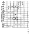
- FIG. 16 is a view showing an example of sliding
window control for a plurality of priorities according
to an embodiment of the present invention;
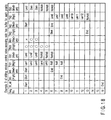
- FIG. 17 is a view showing another example of the
sliding window control for a plurality of priorities;
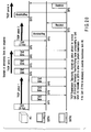
- FIG. 18 is a view showing an example of sliding
window control when the receiving side has a buffer for
each priority;
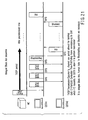
- FIG. 19 is a view showing another example of the
sliding window control when the receiving side has
a buffer for each priority;
- FIG. 20 is a view showing an example of
(immediate) Block Ack sequence;
- FIG. 21 is a view showing a delayed Block Ack
sequence;
- FIG. 22 is a view for explaining Block Ack
scheduling in a TXOP according to an embodiment of
the present invention;
- FIG. 23 is a view showing scheduling of
a plurality of priorities in the TXOP;
- FIG. 24 is a view showing scheduling for
a plurality of destinations in the TXOP;
- FIG. 25 is a view showing a first aggregation
example of the last QoS Data and a Block Ack Request;
- FIG. 26 is a view showing a first aggregation
example of QoS Data and a Block Ack Request;
- FIG. 27 is a view showing a second aggregation
example of QoS Data and a Block Ack Request;
- FIG. 28 is a view showing a third aggregation
example of QoS Data and a Block Ack Request;
- FIG. 29 is a view showing a second aggregation
example of the last QoS Data and a Block Ack Request;
- FIG. 30 is a view showing a third aggregation
example of the last QoS Data and a Block Ack Request
having a plurality of priorities;
- FIG. 31 is a view for explaining the way
aggregation increases the efficiency of Block Ack;
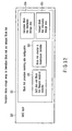
- FIG. 32 is a view showing reception status storage
areas for immediate Block Ack information and delayed
Block Ack information;
- FIG. 33 is a view showing channel access in EDCA;
- FIG. 34 is a view showing mapping of AC and User
Priority;
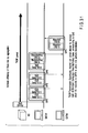
- FIG. 35 is a view for explaining the problem of
frame aggregation in EDCA;
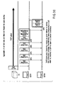
- FIG. 36 is a view showing frame aggregation of
a plurality of TIDs in EDCA according to an embodiment
of the present invention; and
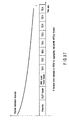
- FIG. 37 is a view showing the channel estimation
accuracy along the time axis when aggregation is
performed for each high-priority TID.
-
-
Embodiments of the present invention will be
described below with reference to the accompanying
drawing.
-
A wireless communication apparatus according to an
embodiment of the present invention communicates with
another communication apparatus via wireless links, and
has processing units corresponding to a physical layer,
MAC layer, and link layer. These processing units are
implemented as analog or digital electronic circuits or
as firmware or the like executed by a CPU incorporated
into an LSI, in accordance with implementation requirements.
An antenna is connected to the processing unit
of the physical layer. The processing unit of the MAC
layer has an aggregation processor. This aggregation
processor includes a carrier sense controller,
retransmission controller, and scheduling controller.
(First Embodiment) [1-1. Frame aggregation
implementation (subqueue for each priority) in HCCA]
-
When MAC frame aggregation is to be performed
while HCCA (HCF Controlled Channel Access) of the IEEE
802.11e is used, a queue configuration is as shown in
FIG. 1 if only one subqueue for retransmission is
present. Referring to FIG. 1, CfQ (Contention free
Queue) is a main queue for storing downlink data from
a QoS access point (HC: Hybrid Coordinator) to a QoS
terminal (QSTA: QoS Station) or uplink data from the
QSTA to the HC, which can be transmitted during a frame
transmission period. MAC frames having various
destinations and priorities are present.
-
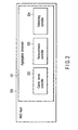
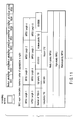
FIG. 2 is a block diagram showing the apparatus
configuration (MAC layer) of an HC. As shown in
FIG. 2, an aggregation processor 201 has a carrier
sense controller 202, a retransmission controller 203,
and a scheduling controller 204. A carrier sense
controller 202 performs media access control on the
basis of the carrier sense information of a physical
layer and a virtual carrier sense information of a MAC
layer. A retransmission controller 203 performs
transmission/reception of partial acknowledgement
frames, retransmission control based on partial
acknowledgement frames, and the like. A scheduling
controller 204 which controls transmission of a polling
frame to a QSTA and the transmission timings of
downlink data is present in the HC of the IEEE 802.11e.
This scheduling controller 204 transmits a polling
frame or data for each priority so as to satisfy
the quality of service required by using TS (Traffic
Stream) setup from a QSTA. The priority parameter
specifies the priority desired for the MAC frame unit
transfer.
-
If it is necessary to transmit data to a certain
QSTA in response to a request from the internal
scheduling processor of the HC, as shown in FIG. 1,
it is possible to store a frame in a subqueue for
retransmission by using the destination and priority
as keys, and transmit the frame as a MAC super frame.
As shown in FIG. 3, it is also possible to store
frames addressed to the same destination and having
a plurality of priorities into one subqueue, and
transmit the frames as a MAC super frame. However,
this complicates the process of performing sliding
window control for each priority by using a Partial Ack
response from the destination terminal. In some cases,
the internal process ability of the apparatus may
decrease.
-
In this embodiment, therefore, as shown in FIG. 4,
a plurality of retransmission control subqueues 102,
103 are prepared in one-to-one correspondence with
priorities. This makes it possible to easily realize
sliding window control for a plurality of priorities
and frame aggregation for each priority, and to perform
parallel processing in the communication apparatus.
First, if the scheduling controller 204 in the HC
generates a request for downlink transmission to a
certain priority (high priority in the example shown in
FIG. 4) of a certain destination (STA1 in the example
shown in FIG. 4), the aggregation processor 201
extracts, from a main queue 101, frames having the
destination and priority corresponding to the request,
and stores them in subqueues 102,103 prepared for the
priority. The number of MPDUs (MAC Protocol Data Unit)
which can be aggregated in one MAC super frame is
predetermined by negotiation. In the example shown in
FIG. 4, the upper limit is eight. Note that the method
of negotiation is not limited to any specific method.
-
As in the example shown in FIG. 4, when high-priority
frames are to be transmitted to STA1 by
downlink transmission, if the number of frames stored
in the high-priority subqueue 102 is less than the
maximum number of frames which can be aggregated in
one MAC super frame, MAC frames addressed to the same
destination and having a different priority are stored
in a corresponding subqueue. In the example shown in
FIG. 4, only five high-priority frames requested by
the scheduling processor are stored in the subqueue
although the maximum number of frames which can be
aggregated is eight, so three medium-priority frames
are stored in a medium-priority subqueue 103. As shown
in FIG. 4, sequence numbers are assigned to each
priority in accordance with the IEEE 802.11e standard.
The request from the internal scheduling processor of
the HC can be generated by any of a method using
"destination, priority" (MAC frames are extracted from
the main queue until the maximum number of frames which
can be aggregated in a MAC super frame is reached),
a method using "destination, priority, the number of
frames" (the scheduling processor designates the number
of MAC frames to be extracted from the main queue), and
a method using "destination, priority 1, the number of
frames of priority 1, priority 2, the number of frames
of priority 2" (the scheduling processor designates
transmission of a plurality of priorities and the
numbers of frames of these priorities). However,
frames are stored in a subqueue for each priority in
the same manner as in FIG. 4 regardless of the method.
-
When a MAC super frame is to be actually formed,
MAC frames are extracted preferentially from a subqueue
having a high priority, and aggregated from the
front of the MAC super frame. Assume in an example
shown in FIG. 5 that five MAC frames are stored in
a high-priority subqueue 102 and three MAC frames are
stored in a medium-priority subqueue 103. The total of
these frames is equal to the maximum number (in the
example shown in FIG. 5, eight) of frames which can be
stored in one MAC super frame. However, if no frame
having the corresponding destination and priority
exists in the main queue, the number of frames can be
smaller than the maximum number of frames which can be
aggregated. Also, if only two medium-priority MAC
frames exist in the main queue in the case shown in
FIG. 5, low-priority frames are stored in a low-priority
subqueue 104, and aggregated in the rear of
the MAC super frame. Frames are aggregated for each
priority in order to protect high-priority MPDUs
because the longer a physical frame, the lower the
channel estimation accuracy in the latter half of the
frame, and the more easily an error occurs.
-
Note that this embodiment is applicable not only
to downlink traffic transmission from an HC but also to
uplink traffic transmission from a QSTA.
(Second Embodiment) [1-2. Frame aggregation implementation
(Partial Ack Bitmap for each priority) in HCCA]
-
A case in which, for MPDUs aggregated for each
priority in a MAC super frame, a relative order in
which priorities are aggregated is predetermined such
that high-priority frames are aggregated first, medium-priority
frames are aggregated second, and low-priority
frames are aggregated third, and both transmitting and
receiving terminals recognize this, will be explained
below. As shown in FIG. 6, a MAC super frame receiving
terminal describes the reception status of the
aggregated MPDUs in a Partial Ack Bitmap, and returns
a Partial Ack. In this case, the types and order of
the priorities of the aggregated MPDUs have no
influence on the formation of the Partial Ack Bitmap.
When the Partial Ack is returned to the MAC super frame
transmitting terminal, bitmap information for each
priority can be determined in the Partial Ack Bitmap
from the number of MAC frames stored for retransmission
in a subqueue for the priority. By cutting out the
transmission status of each priority, sliding window
control for each priority can be performed more
efficiently.
-
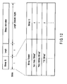
If, as shown in FIG. 7, MPDUs to be aggregated in
a MAC super frame are not necessarily sorted for each
priority, it is difficult to immediately determine
the transmission status of each priority even when a
Partial Ack is received from the destination terminal.
To solve this problem, the MAC super frame transmitting
side may have cache information which indicates the
location of aggregation of each priority. However, it
is also possible to prepare a Partial Ack Bitmap for
each priority as shown in FIG. 8. An extended Partial
Ack frame has a "Number of Priority" field and a
Partial Ack Bitmap for each priority. The "Number of
Priority" field indicates the number of priorities
present in a Partial Ack. A "TID" field corresponds to
the value of a TID (Traffic Identifier) of the IEEE
802.11e. As shown in FIG. 8, in the extended Partial
Ack frame, a Partial Ack Bitmap is present for each
TID. Note that the numbers of the "TID" fields and
"Partial Ack Bitmaps" in the Partial Ack frame can be
changed in accordance with the number of priorities
aggregated in the MAC super frame. FIG. 8 shows a case
in which MPDUs having three priorities exist in a MAC
super frame. In the example shown in FIG. 8, the
maximum number of MPDUs which can be aggregated in the
MAC super frame is eight, and the field size of the
Partial Ack Bitmap is one octet. However, this size
may also be changed in accordance with the maximum
number of aggregations.
-
Assume, as shown in FIG. 9, that MPDUs aggregated
in a MAC super frame are found to be errors by CRC
calculations. In this case, the MAC super frame
receiving side cannot determine the reception status of
each priority. As shown in FIG. 10, therefore, a "TID
Bitmap" field is newly added to the MAC super frame
header. A "Num of TIDs" field indicates the number of
priorities aggregated in the MAC super frame. The "TID
Bitmap" field follows a "TID" field representing the
traffic identifier (the length of this field is one
octet, four bits are allocated to the TID, and four
remaining bits are allocated to a reservation field).
The "TID Bitmap" field is information indicating the
position in the MAC super frame in which a frame having
the corresponding priority is aggregated. This bitmap
information is contained in the MAC super frame header.
If a partial MPDU error except for a MAC super frame
header CRC error occurs, therefore, the MAC super frame
receiving terminal can determine the position where
each priority exists and the reception status of the
priority.
-
FIG. 11 shows an example of the use of the "TID
Bitmap". Assume, as shown in FIG. 11, that MPDUs
having three priorities are aggregated in the order of
"medium priority", "high priority", "medium priority",
"high priority", "low priority", "high priority", "high
priority", and "low priority". Note that the maximum
number of MPDUs which can be aggregated is eight in
this example shown in FIG. 11, but the maximum number
is of course not fixed to this number. In this case,
the "TID Bitmap" of the high priority is "01010110",
the "TID Bitmap" of the medium priority is "10100000",
and the "TID Bitmap" of the low priority is "00001001".
That is, the "TID Bitmap" of each priority is
identification information which indicates the position
in the MAC super frame in which an MPDU corresponding
to that priority exists.
-
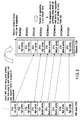
If a "Bitmap Information" field as shown in
FIG. 12 is used as the format of the "TID Bitmap", the
"Number of TIDs" field may also be omitted. The length
of the "TID Bitmap" field in the MAC super frame header
corresponds to the maximum number of MPDUs which can
be aggregated. Since, however, both the transmitting
and receiving sides recognize the maximum number of
aggregations in advance through negotiation, the
receiving side can also determine the length of the
"TID Bitmap" field. In an example shown in FIG. 13,
MPDUs having three types of priorities are aggregated
in a MAC super frame header in which the maximum number
of aggregations is eight, the length of a "TID" field
in the MAC super frame header is one octet as a fixed
length, and the length of a "TID Bitmap" field is
also one octet (the maximum number of aggregations
is eight). Accordingly, the length of a "Bitmap
Information" field (the value in units of octets
described in a "Length" field) is six octets.
An identifier for the "TID Bitmap" is described in
a "Bitmap ID" field, and the number is 2 in the example
shown in FIG. 12. However, the number is of course not
limited to 2.
-
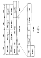
FIG. 14 shows the flow of communication using a
MAC super frame obtained by extending a "TID Bitmap"
field, and a Partial Ack obtained by extending a
Partial Ack Bitmap for each priority. As shown in
FIG. 14, when MPDUs having a plurality of priorities
are aggregated in a MAC super frame, identification
information indicating the position where each priority
is present is described in a "TID Bitmap" field of
the MAC super frame header. In the example shown in
FIG. 14, the logic is so determined that "1 indicates
the presence". However, implementation by negative
logic is of course also possible. A MAC super frame
receiving terminal performs header CRC calculation of
the MAC super frame header, and, if the header is not
an error, executes CRC calculation of each aggregated
MPDU. Also, a Partial Ack Bitmap for each priority can
be easily formed by using the "TID Bitmap" in the MAC
super frame header. When a Partial Ack Bitmap for
each priority is to be formed in the example shown in
FIG. 14, it is determined from the "TID Bitmap" that
four high-priority MPDUs exist. In addition, the two
forward MPDUs are found to be errors by CRC calculations,
so the bitmap configuration is "00110000".
The length of a Partial Ack Bitmap is designated in
units of octets. Consequently, in the example shown
in FIG. 14, the four forward bits form information
indicating the reception status. The four backward
bits carry no special significance.
-
When a Partial Ack obtained by extending a Partial
Ack Bitmap for each priority is received by a MAC super
frame transmitting terminal, a procedure such as
deletion of a MAC frame from a retransmission subqueue
prepared for each priority can be performed in
parallel, so more efficient processing can be realized.
(Third Embodiment) [1-3. Frame aggregation implementation
(sliding window for each priority) in HCCA]
-
When a Partial Ack frame having a Partial Ack
Bitmap for each priority is received, MAC frames stored
in a subqueue prepared for each priority are deleted
from the queue. As shown in FIG. 15, when MAC frames
are stored in high-priority and medium-priority
subqueues, MAC frames correctly transmitted to the
destination are deleted by referring to a Partial Ack
Bitmap for each priority. Assume that MPDUs in a MAC
super frame are divisionally aggregated for each
priority, and frames having high priority are packed
forward. In this case, the contents of the Partial Ack
Bitmap are interpreted from the number of MAC frames
stored in a subqueue for each priority, and MAC frames
having each priority are deleted from a subqueue.
-
Although sliding window control is performed for
each priority, cases as shown in FIGS. 16 to 19 will
be explained. Each of FIGS. 16 to 19 shows a case
in which two types of MPDUs having high and medium
priorities are aggregated in a MAC super frame.
However, the number of priorities is not limited when
the present invention is practiced. Referring to
FIGS. 16 to 19, W_all defines the maximum number of MAC
frames which can be continuously transmitted. A window
W (high) and window W (medium) at each time indicates
the maximum number of MPDUs which have a certain
priority and can be aggregated at once. Windows slide
backward in accordance with the status of a Partial
Ack Bitmap. Also, FIGS. 16 to 19 are based on the
assumption that the maximum number of MPDUs which can
be aggregated in a MAC super frame is eight regardless
of the priority. Furthermore, FIGS. 16 and 17
illustrate sliding window control when the receiving
side has one physical buffer, and FIGS. 18 and 19
illustrate sliding window control when a plurality of
physical buffers are prepared on the receiving side in
one-to-one correspondence with priorities. Preparing a
plurality of physical buffers in one-to-one correspondence
with priorities has the advantage that processes
can be executed in parallel in a receiver. If a
plurality of receiving buffers are present in one-to-one
correspondence with priorities, a MAC super frame
transmitting terminal determines a window W in
accordance with the receiving buffer size of each
priority of the destination terminal. The present
invention is not limited to any specific negotiation
method for determining the window size.
-
Referring to FIGS. 16 to 19, "Null" means that no
frame to be aggregated is present in the main queue.
"Zero" means that the last transmitted frame is
correctly received. "NoAdd" means that regardless of
whether a corresponding frame is present in the main
queue, no new frame can be packed in relation to the
maximum number of frames which can be aggregated in
one MAC super frame.
-
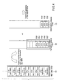
First, sliding window control when the MAC super
frame receiving side has only one physical buffer will
be explained below on the basis of examples shown in
FIGS. 16 and 17. A window size W (for high-priority)
at each time shown in FIGS. 16 and 17 is determined
on the basis of a (single) physical buffer of the
destination terminal. A window size (for medium-priority)
changes its length in accordance with the
number of aggregated high-priority frames.
-
Referring to FIG. 16, assume that five high-priority
MPDUs and three medium-priority MPDUs are
aggregated and transmitted. Since five aggregated
high-priority MPDUs are smaller than a window size W1
(for high-priority), an extra space is produced, so
a window size W1 (for medium-priority) can ensure
a space of three MPDUs. When MPDUs having a plurality
of priorities are to be aggregated, it is desirable to
divide these MPDUs for each priority, and aggregate
high-priority MPDUs forward. After that, on the basis
of information of a Partial Ack from the destination,
it is found that all the high-priority MPDUs are
successfully received and the first one of the medium-priority
MPDUs is an error. In W2 (for high-priority),
the high-priority MPDUs undergo sliding window.
However, since the first frame (the first one of the
three transmitted frames) of the medium-priority MPDUs
is an error, it is confirmed that two medium-priority
frames are stored in the buffer of the destination
terminal. Accordingly, high-priority MPDUs which can
be newly aggregated are five MPDUs from Seq6 to Seg10.
Since no more high-priority MPDUs can be packed,
"NoAdd" is indicated. For medium-priority MPDUs, the
window size is not changed, and only retransmission
frame Seq1 is a target MPDU to be aggregated.
-
The example shown in FIG. 17 is as follows.
The operation up to TX1 is the same as in FIG. 16. On
the basis of a Partial Ack from the destination, it is
found that the second high-priority MPDU is an error,
and all the medium-priority MPDUs are successfully
transmitted. If no high-priority MAC frame to be
packed is present in the main queue after sliding
window control is performed, the window size for
the medium priority can be increased. Since three
high-priority MPDUs are stored in the buffer of the
receiving side, four frames including one high-priority
frame for retransmission are presumably used in the
(single) receiving buffer. Therefore, 8 as a window
size W2 (for high-priority) minus 4 is a window size W2
(for medium-priority). In this case, the window size
(for high-priority) is a fixed length. That is, four
frames from Seq4 to Seq7 can be aggregated in a MAC
super frame.
-
Retransmission control as described above is
performed to aggregate MPDUs within the range indicated
by W_all. Also, when additional frames are to be
aggregated, high-priority MPDUs are always preferentially
aggregated.
-
FIGS. 18 and 19 in each of which the receiver side
has a plurality of physical buffers in one-to-one
correspondence with priorities will be explained below.
When a plurality of physical buffers are prepared,
parallel processing can be performed in a wireless
communication apparatus. In this case, a MAC super
frame transmitting terminal is notified of the buffer
size of the receiving side for each priority, and the
transmitting side determines the window size W for
each priority. In FIG. 18 and 19, the reception buffer
size for high-priority is 8 MPDUs, and the buffer size
for medium-priority is 6 MPDUs. But this number is
implementation-dependent. As indicated by TX1 (for
high-priority) and TX1 (for medium-priority) in
FIG. 18, assume that five high-priority MPDUs and three
medium-priority MPDUs are transmitted by aggregating
them in a MAC super frame. Null in TX1 (for high-priority)
means that no high-priority frame for
a certain destination exists. In the example shown
in FIG. 18, this Null indicates that only five high-priority
frames are stored in the main queue at time
TX1. After MAC frames are deleted from subqueues in
accordance with the contents of Partial Ack Bitmaps
formed in RX1 (for high-priority) and RX1 (for medium-priority),
it is found that one medium-priority frame
needs to be retransmitted. After that, a window W (for
high-priority) and window W (for medium-priority) at
each time are slid for each priority. If frames having
only one type of priority are to be aggregated in a MAC
super frame, these frames can be packed to "End" of the
window W at each time. However, one medium-priority
frame to be retransmitted exists. At TX2 (for high-priority),
therefore, seven frames from Seq. Nos. 6 to
12 are targets to be aggregated in a MAC super frame.
At TX2 (for medium-priority), the total of the seven
high-priority frames and the one medium-priority frame
to be retransmitted reaches the maximum number of
frames which can be aggregated in one MAC super frame,
so no more frames are added.
-
As shown in FIG. 19, sliding window processing
is performed after a Partial Ack is received. As a
consequence, at TX2 (for high-priority), only two high-priority
frames to be retransmitted are aggregated.
Therefore, at TX2 (for medium-priority), six (the
maximum, medium-priority buffer amount designated on
the receiving side) frames from Seq. Nos. 4 to 9 can be
aggregated. The number of MPDUs to be continuously
transmitted is so determined that the window size W
falls within the range of W_all for each priority.
(Fourth Embodiment) [2-1. Increase efficiency of Block
Ack processing]
-
Block Ack defined in the IEEE 802.11e supports
efficient transmission by Selective Repeat Retransmission.
FIG. 20 shows the sequence of standard immediate
Block Ack procedure. As shown in FIG. 20, Block Ack
transmission in HCCA is adjusted within the range of
a channel use period (TXOP: Transmission Opportunity)
designated by a QoS access point (HC: Hybrid
Coordinator). Note that the example in FIG. 20 shows
the way polling to a QSTA or downlink data transmission
is performed during a CAP (Controlled Access Period).
The HC shown in FIG. 20 transmits a QoS CF-Poll frame
(a polling frame corresponding to QoS which the HC
transmits to a QSTA to permit it to perform transmission)
to QSTA 1. QSTA 1 can freely transmit frames
within the range of TXOP. In FIG. 20, QSTA 1 transmits
QoS Data as a target of Block Ack to QSTA 2 in a burst
manner and terminates the period. After that, in TXOP
period 2, the HC transmits QoS Data as a target of
Block Ack to QSTA 2 at SIFS intervals in a burst
manner. In TXOP period 3, QSTA 1 transmits a Block Ack
Request to QSTA 2 and waits for Block Ack. In TXOP
period 4, the HC transmits a Block Ack Request to QSTA
2 and waits for Block Ack.
-
In the Block Ack of the IEEE 802.11e, to form
a Block Ack Bitmap indicating the reception status,
the receiver side must manage a maximum of 1,024 bits
reception status of 64 MSDUs (MSDU: MAC Service Data
Unit) for each destination and each TID (Traffic
Identifier). According to the present specifications,
no Block Ack Request need be transmitted immediately
after QoS Data which is transmitted in a burst manner
from a certain destination. Therefore, whenever a
Block Ack Request is received, Block Ack is formed by
checking the reception status of the corresponding
destination (and TID). This generally increases the
processing load on the receiver side. Consequently, it
is sometimes impossible to reply Block Ack during the
period of SIFS and realize transmission except for
delayed Block Ack transmission as shown in FIG. 21.
In delayed Block Ack, Block Ack is transmitted after
a predetermined time has elapsed since a Block Ack
Request is received, so the transmission efficiency
obviously comes down. This is so because if Block Ack
transmission executed in a transmission period of a
certain terminal extends to the next TXOP period, QoS
Data of Block Ack transmission from another terminal
interrupts, and this complicates a mechanism for
managing the reception statuses on the receiving side.
-
In the first arrangement of this embodiment,
therefore, a terminal which has obtained TXOP performs
scheduling so that all of a series of sequences, i.e.,
QoS Data burst transmission, Block Ack Request
transmission, and Block Ack reception, are included in
the period. FIG. 22 shows a frame sequence. In the
Block Ack sequence shown in FIG. 20, even when a
certain TXOP period is given, a Block Ack Request is
not necessarily transmitted within this TXOP period.
However, in this embodiment shown in FIG. 22,
scheduling is performed inside the terminal such
that QoS Data burst transmission, Block Ack Request
transmission, and Block Ack reception are certainly
complete within the TXOP period. More specifically,
the number of QoS Data to be transmitted by burst
transmission is reduced, and a Block Ack Request is
transmitted with a margin so that Block Ack can be
reliably received. The timing of Block Ack Request
transmission is appropriately calculated from the
duration, number of transmitting frames, and physical
transmission rate of QoS Data. In the present
invention, the method of calculating the timing of
Block Ack Request transmission is not limited to any
specific method. Note that in a certain TXOP period,
QoS Data having a plurality of priorities (TIDs) can
be transmitted in a burst manner. Even in this case,
as shown in FIG. 23, frame transmission scheduling
is so performed as to be able to receive Block Ack of
each TID within the period of TXOP by, e.g., limiting
the number of QoS Data to be transmitted by burst
transmission. In addition, as shown in FIG. 24, Block
Ack transmission can be performed for a plurality of
destinations in the TXOP period. The transmitting
terminal performs frame transmission scheduling in this
case as well, so as to be able to receive Block Ack
from each destination within the TXOP period. If only
a time during which one QoS Data can be transmitted but
no Block Ack Request can be transmitted remains, Block
Ack data transmission to the destination (or TID) is
desirably postponed to the next opportunity (TXOP).
-
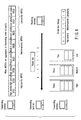
In the second arrangement of this embodiment,
a Block Ack Request is transmitted by aggregating it in
the last QoS Data to be transmitted by burst transmission
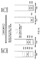
in a given TXOP period. As shown in FIG. 25,
the channel efficiency can be more effectively used
by transmitting QoS Data and a Block Ack Request by
aggregating them in one physical frame. FIGS. 26 and
27 show frame formats of the aggregated QoS Data and
Block Ack Request. That is, FIG. 26 shows a format
which includes, as a MAC payload, information
indicating the divisions (lengths) of aggregated MPDUs
on the basis of information such as "Type", "Sub Type",
and "Length" of the MAC header of the IEEE 802.11 (QoS
control information of the IEEE 802.11e is sometimes
included). This field is called an aggregation field.
Also, the 802.11 MAC header and an FCS (Frame Check
Sequence) for the field indicating the length of the
MPDU are added. Bitmap information for extending
functions may also be added to the aggregation field.
FIG. 27 shows an example in which an identification
header indicating the lengths of aggregated MPDUs is
newly formed. This header is called an aggregation
header. Header CRC for calculating a header error
is added to this aggregation header. If the header
has an error, all aggregated frames are discarded. The
aggregation header is added before the aggregated MPDU
payload such as the aggregated QoS Data and Block Ack
Request. Note that in the format of the aggregation
header shown in FIG. 27, the maximum number of MPDUs
which can be aggregated is eight. Therefore, it is
also possible to aggregate a plurality of QoS Data as
shown in FIG. 28, and aggregate only QoS Data as a
target of Block Ack instead of a Block Ack Request.
The maximum number of MPDUs which can be aggregated
in one physical frame must be recognized beforehand by
the transmitting and receiving terminals through some
negotiation. However, a practical negotiation method
is not a target of the present invention.
-
As shown in FIG. 29, only QoS Data may also be
aggregated in one physical frame and transmitted in
a burst manner. As shown in FIG. 30, even when QoS
Data having a plurality of priorities are transmitted
by burst transmission in a certain TXOP period, the
transmission efficiency can be increased by aggregating
a Block Ack Request for a plurality of TIDs in the last
QoS Data and transmitting the data. The effect further
increases if the destination terminal also transmits
Block Ack for each TID by aggregation. A plurality of
QoS Data to be transmitted by burst transmission at
SIFS intervals shown in FIG. 30 may also be transmitted
by aggregating them in one physical frame as shown in
FIG. 31.
-
The receiver side which receives QoS Data by Block
Ack will be explained below.
-
FIG. 32 is a block diagram showing a Block Ack
procedure receiving side configuration included in MAC
layer of the wireless communication apparatus corresponding
to the receiver side which receives QoS Data
by Block Ack. The MAC layer of the receiver has a
controller 322 for receiving QoS Data transmitted by
burst transmission and a Block Ack Request, and a
controller 323 for creating Block Ack. The receiver
also has a storage area 324 for immediate Block Ack,
and a storage area 325 for delayed Block Ack. This
embodiment assumes that the area for immediate Block
Ack is 324 relatively fast access storage, and the area
for delayed Block Ack 325 is other types of storage.
-
When burst reception of QoS Data from a certain
destination is started, the reception statuses of
data frames are stored in the immediate Block Ack
information storage area 324. This area can store
1,024 reception statuses for each TID. 1,024 is
a value obtained by multiplying the maximum number of
MSDUs (MAC Service Data Unit) which can be continuously
transmitted while using a Block Ack period ("64" in
IEEE802.11e) by the maximum number of fragment frames
per MSDU ("16" in IEEE802.11). As shown in FIG. 22, if
a Block Ack Request is transmitted from the destination
whose reception statuses are stored in the immediate
Block Ack information storage area 324 within the TXOP
period, a Block Ack response is immediately returned.
Since QoS Data from a plurality of destinations are not
mixed, the load of the process of forming Block Ack for
one destination can be reduced.
-
Also, in the example shown in FIG. 20 in which,
while QSTA 2 is continuously receiving QoS Data as a
target of Block Ack from the HC in a burst manner, the
next TXOP period begins and QoS Data reception by Block
Ack from QSTA 1 as another destination is started, if
the immediate Block Ack information storage 324 area
shown in FIG. 32 has no extra space, reception status
information for the HC stored in this area is moved to
the delayed Block Ack information storage area 325,
and reception status information of the new destination
(QSTA 1) is formed in the immediate Block Ack
information storage area 324. After that, the receiver
responds to the old destination by delayed Block Ack
(the HC in FIG. 20).
-
In this embodiment as described above, it is
possible to increase the Block Ack processing
efficiency, and reduce the processing load on the
receiver side in relation to Block Ack formation.
-
Note that in EDCA, RTS-CTS is used to notify
another terminal of a channel use period used by its
own terminal. However, TXOP calculations are so
performed that a series of sequences, i.e., QoS Data
transmission, Block Ack Request transmission, and
Block Ack reception, can be performed in the duration
(channel use period) of the RTS frame.
(Fifth Embodiment) [3-1. Frame aggregation in EDCA]
-
In EDCA (Enhanced Distributed Channel Access),
a plurality of ACs (Access Categories) are formed for
each priority, and these ACs perform CSMA/CA procedure
in parallel. Each AC has its own IFS (AIFS:
Arbitration Interframe Space) period. The higher
the priority of an AC, the shorter time interval is
adopted. If an internal collision occurs at a MAC
layer, MAC frames of a high-priority AC are transmitted
to a PHY layer preferentially, and a low-priority AC
invokes a random backoff procedure again after
increasing CW (contention window). FIG. 33 shows
channel access in EDCA. Also, as expressed in FIG. 34,
during EDCA, data from an upper layer is mapped in 0
to 7 of a TID (Traffic Identifier) in accordance with
User Priority of the IEEE 802.1D. The mapped TID is
distributed to ACs. As a consequence, MAC frames
having a plurality of TIDs are stored in an AC.
-
As shown in FIG. 35, when a plurality of MPDUs are
aggregated in one physical frame in EDCA, each MPDU is
packed for each destination and each TID. This is so
because EDCA is an access control method (prioritized
CSMA/CA access) based on competition, and hence does
not guarantee the quality of each traffic stream unlike
in HCCA. That is, a MAC frame is extracted from the
head of a main queue prepared for each AC, and a frame
equal in destination and TID to the extracted frame is
aggregated. In this case, as shown in FIG. 35, the
number of MAC frames is sometimes smaller than the
maximum number of MPDUs which can be aggregated in one
physical frame, so the channel use efficiency may not
be maximally utilized.
-
In this embodiment, therefore, when a certain AC
obtains transmission right and transmits a data frame,
MAC frames are extracted from the head of a main queue
for each AC. If the number of the extracted MAC frames
is smaller than the maximum number of MAC frames which
can be aggregated in one physical frame, a MAC frame
of another TID (in EDCA, the number of types of TIDs
stored in an AC is defined to be two) is aggregated.
In this case, a subqueue which stores, for the purpose
of retransmission, MAC frames extracted from the main
queue for each AC is desirably prepared for each TID.
When a subqueue is thus prepared for each TID, sliding
window control can be performed more simply.
-
As shown in FIG. 34, the priority changes in
accordance with a TID even in the same AC. In this
embodiment, therefore, a frame is aggregated by
dividing it for each high-priority TID. In OFDM,
channel estimation (estimation of phase and amplitude
distortions of a transmission channel for each
subcarrier) is realized by using a known preamble
signal stored in a receiver. In a wireless LAN which
is packet mode communication and in which variations of
a transmission channel with time in a packet (frame)
are small, the general approach is to independently
perform channel estimation at the start of a preamble
signal for each packet. However, if the frame length
increases as in the case of an aggregated frame,
the transmission channel varies with time, so the
estimation result calculated when the preamble is
received is sometimes not accurately reflected in the
latter half of the frame (see FIG. 37). Accordingly,
the error tolerance of a data frame having a high-priority
TID can be effectively raised by aggregating
high-priority MPDUs forward.
-
Also, sequence numbers are consecutively assigned
to each TID. Therefore, a wireless communication
apparatus for transmitting aggregated frames performs
sliding window control for each TID in accordance with
a partial response from the receiving side.
-
In the above explanation, frames having a
plurality of TIDs in the same AC are aggregated.
However, if no MAC frame having another TID exists in
a certain AC, and if the transmission timings of a
plurality of ACs internally overlap each other due to
an internal collision, it is also possible to extract
MAC frames having the same destination from a main
queue of an AC whose priority is lower than that of the
certain AC, and aggregate them in one physical frame.
In this case, internal collisions occur between a
plurality of ACs. Therefore, it is desirable for low-priority
(and medium-priority) ACs to take random
backoff by increasing contention windows after the
aggregated frames are transmitted.
-
As described above, this embodiment can increase
the effect of frame aggregation in EDCA.
-
In the embodiment of the present invention, FCS,
which contains an IEEE32-bit cyclic redundancy check,
for each MPDU can be used (as shown in FIG. 8 and
FIG. 26) as a substitute for CRC information.