EP1602625A1 - Halbleitermodul mit einem Halbleiter-Sensorchip und einem Kunststoffgehäuse sowie Verfahren zu dessen Herstellung - Google Patents
Halbleitermodul mit einem Halbleiter-Sensorchip und einem Kunststoffgehäuse sowie Verfahren zu dessen Herstellung Download PDFInfo
- Publication number
- EP1602625A1 EP1602625A1 EP05090155A EP05090155A EP1602625A1 EP 1602625 A1 EP1602625 A1 EP 1602625A1 EP 05090155 A EP05090155 A EP 05090155A EP 05090155 A EP05090155 A EP 05090155A EP 1602625 A1 EP1602625 A1 EP 1602625A1
- Authority
- EP
- European Patent Office
- Prior art keywords
- semiconductor module
- sensor
- semiconductor
- components
- sensor chip
- Prior art date
- Legal status (The legal status is an assumption and is not a legal conclusion. Google has not performed a legal analysis and makes no representation as to the accuracy of the status listed.)
- Granted
Links
- 239000004065 semiconductor Substances 0.000 title claims abstract description 148
- 229920003023 plastic Polymers 0.000 title claims abstract description 39
- 238000004519 manufacturing process Methods 0.000 title claims abstract description 11
- 238000000608 laser ablation Methods 0.000 claims abstract description 21
- 238000000034 method Methods 0.000 claims abstract description 15
- 239000004020 conductor Substances 0.000 claims description 33
- 150000001875 compounds Chemical class 0.000 claims description 18
- 238000005516 engineering process Methods 0.000 claims description 17
- 239000000463 material Substances 0.000 claims description 12
- 239000000203 mixture Substances 0.000 claims description 12
- 230000003287 optical effect Effects 0.000 claims description 12
- 229910000679 solder Inorganic materials 0.000 claims description 11
- 239000012780 transparent material Substances 0.000 claims description 11
- 239000000758 substrate Substances 0.000 claims description 10
- 230000008901 benefit Effects 0.000 claims description 8
- 239000013013 elastic material Substances 0.000 claims description 5
- 230000005496 eutectics Effects 0.000 claims description 4
- 238000009792 diffusion process Methods 0.000 claims description 3
- 239000000835 fiber Substances 0.000 claims description 2
- 230000000930 thermomechanical effect Effects 0.000 description 4
- 238000000465 moulding Methods 0.000 description 3
- 238000010276 construction Methods 0.000 description 2
- 239000012530 fluid Substances 0.000 description 2
- 238000002844 melting Methods 0.000 description 2
- 230000008569 process Effects 0.000 description 2
- 230000002745 absorbent Effects 0.000 description 1
- 239000002250 absorbent Substances 0.000 description 1
- 230000001133 acceleration Effects 0.000 description 1
- 239000000853 adhesive Substances 0.000 description 1
- 230000001070 adhesive effect Effects 0.000 description 1
- XAGFODPZIPBFFR-UHFFFAOYSA-N aluminium Chemical compound [Al] XAGFODPZIPBFFR-UHFFFAOYSA-N 0.000 description 1
- 229910052782 aluminium Inorganic materials 0.000 description 1
- 238000004458 analytical method Methods 0.000 description 1
- 230000009286 beneficial effect Effects 0.000 description 1
- 238000009530 blood pressure measurement Methods 0.000 description 1
- 239000011248 coating agent Substances 0.000 description 1
- 238000000576 coating method Methods 0.000 description 1
- 239000002131 composite material Substances 0.000 description 1
- 230000008878 coupling Effects 0.000 description 1
- 238000010168 coupling process Methods 0.000 description 1
- 238000005859 coupling reaction Methods 0.000 description 1
- 230000001419 dependent effect Effects 0.000 description 1
- 238000011161 development Methods 0.000 description 1
- 230000018109 developmental process Effects 0.000 description 1
- 230000003628 erosive effect Effects 0.000 description 1
- 239000007789 gas Substances 0.000 description 1
- 238000004868 gas analysis Methods 0.000 description 1
- PCHJSUWPFVWCPO-UHFFFAOYSA-N gold Chemical compound [Au] PCHJSUWPFVWCPO-UHFFFAOYSA-N 0.000 description 1
- 229910052737 gold Inorganic materials 0.000 description 1
- 239000010931 gold Substances 0.000 description 1
- -1 gold-aluminum Chemical compound 0.000 description 1
- 230000017525 heat dissipation Effects 0.000 description 1
- 230000006872 improvement Effects 0.000 description 1
- 239000007788 liquid Substances 0.000 description 1
- 238000005259 measurement Methods 0.000 description 1
- 230000008018 melting Effects 0.000 description 1
- 238000012536 packaging technology Methods 0.000 description 1
- 230000035515 penetration Effects 0.000 description 1
- 238000005476 soldering Methods 0.000 description 1
- 238000005382 thermal cycling Methods 0.000 description 1
Images


Classifications
-
- B—PERFORMING OPERATIONS; TRANSPORTING
- B81—MICROSTRUCTURAL TECHNOLOGY
- B81B—MICROSTRUCTURAL DEVICES OR SYSTEMS, e.g. MICROMECHANICAL DEVICES
- B81B7/00—Microstructural systems; Auxiliary parts of microstructural devices or systems
- B81B7/0032—Packages or encapsulation
- B81B7/0067—Packages or encapsulation for controlling the passage of optical signals through the package
-
- B—PERFORMING OPERATIONS; TRANSPORTING
- B81—MICROSTRUCTURAL TECHNOLOGY
- B81B—MICROSTRUCTURAL DEVICES OR SYSTEMS, e.g. MICROMECHANICAL DEVICES
- B81B2207/00—Microstructural systems or auxiliary parts thereof
- B81B2207/01—Microstructural systems or auxiliary parts thereof comprising a micromechanical device connected to control or processing electronics, i.e. Smart-MEMS
- B81B2207/012—Microstructural systems or auxiliary parts thereof comprising a micromechanical device connected to control or processing electronics, i.e. Smart-MEMS the micromechanical device and the control or processing electronics being separate parts in the same package
-
- H—ELECTRICITY
- H01—ELECTRIC ELEMENTS
- H01L—SEMICONDUCTOR DEVICES NOT COVERED BY CLASS H10
- H01L2224/00—Indexing scheme for arrangements for connecting or disconnecting semiconductor or solid-state bodies and methods related thereto as covered by H01L24/00
- H01L2224/01—Means for bonding being attached to, or being formed on, the surface to be connected, e.g. chip-to-package, die-attach, "first-level" interconnects; Manufacturing methods related thereto
- H01L2224/26—Layer connectors, e.g. plate connectors, solder or adhesive layers; Manufacturing methods related thereto
- H01L2224/31—Structure, shape, material or disposition of the layer connectors after the connecting process
- H01L2224/32—Structure, shape, material or disposition of the layer connectors after the connecting process of an individual layer connector
- H01L2224/321—Disposition
- H01L2224/32151—Disposition the layer connector connecting between a semiconductor or solid-state body and an item not being a semiconductor or solid-state body, e.g. chip-to-substrate, chip-to-passive
- H01L2224/32221—Disposition the layer connector connecting between a semiconductor or solid-state body and an item not being a semiconductor or solid-state body, e.g. chip-to-substrate, chip-to-passive the body and the item being stacked
- H01L2224/32245—Disposition the layer connector connecting between a semiconductor or solid-state body and an item not being a semiconductor or solid-state body, e.g. chip-to-substrate, chip-to-passive the body and the item being stacked the item being metallic
-
- H—ELECTRICITY
- H01—ELECTRIC ELEMENTS
- H01L—SEMICONDUCTOR DEVICES NOT COVERED BY CLASS H10
- H01L2224/00—Indexing scheme for arrangements for connecting or disconnecting semiconductor or solid-state bodies and methods related thereto as covered by H01L24/00
- H01L2224/01—Means for bonding being attached to, or being formed on, the surface to be connected, e.g. chip-to-package, die-attach, "first-level" interconnects; Manufacturing methods related thereto
- H01L2224/42—Wire connectors; Manufacturing methods related thereto
- H01L2224/47—Structure, shape, material or disposition of the wire connectors after the connecting process
- H01L2224/48—Structure, shape, material or disposition of the wire connectors after the connecting process of an individual wire connector
- H01L2224/481—Disposition
- H01L2224/48135—Connecting between different semiconductor or solid-state bodies, i.e. chip-to-chip
- H01L2224/48137—Connecting between different semiconductor or solid-state bodies, i.e. chip-to-chip the bodies being arranged next to each other, e.g. on a common substrate
-
- H—ELECTRICITY
- H01—ELECTRIC ELEMENTS
- H01L—SEMICONDUCTOR DEVICES NOT COVERED BY CLASS H10
- H01L2224/00—Indexing scheme for arrangements for connecting or disconnecting semiconductor or solid-state bodies and methods related thereto as covered by H01L24/00
- H01L2224/01—Means for bonding being attached to, or being formed on, the surface to be connected, e.g. chip-to-package, die-attach, "first-level" interconnects; Manufacturing methods related thereto
- H01L2224/42—Wire connectors; Manufacturing methods related thereto
- H01L2224/47—Structure, shape, material or disposition of the wire connectors after the connecting process
- H01L2224/48—Structure, shape, material or disposition of the wire connectors after the connecting process of an individual wire connector
- H01L2224/481—Disposition
- H01L2224/48151—Connecting between a semiconductor or solid-state body and an item not being a semiconductor or solid-state body, e.g. chip-to-substrate, chip-to-passive
- H01L2224/48221—Connecting between a semiconductor or solid-state body and an item not being a semiconductor or solid-state body, e.g. chip-to-substrate, chip-to-passive the body and the item being stacked
- H01L2224/48245—Connecting between a semiconductor or solid-state body and an item not being a semiconductor or solid-state body, e.g. chip-to-substrate, chip-to-passive the body and the item being stacked the item being metallic
- H01L2224/48247—Connecting between a semiconductor or solid-state body and an item not being a semiconductor or solid-state body, e.g. chip-to-substrate, chip-to-passive the body and the item being stacked the item being metallic connecting the wire to a bond pad of the item
-
- H—ELECTRICITY
- H01—ELECTRIC ELEMENTS
- H01L—SEMICONDUCTOR DEVICES NOT COVERED BY CLASS H10
- H01L2224/00—Indexing scheme for arrangements for connecting or disconnecting semiconductor or solid-state bodies and methods related thereto as covered by H01L24/00
- H01L2224/01—Means for bonding being attached to, or being formed on, the surface to be connected, e.g. chip-to-package, die-attach, "first-level" interconnects; Manufacturing methods related thereto
- H01L2224/42—Wire connectors; Manufacturing methods related thereto
- H01L2224/47—Structure, shape, material or disposition of the wire connectors after the connecting process
- H01L2224/48—Structure, shape, material or disposition of the wire connectors after the connecting process of an individual wire connector
- H01L2224/484—Connecting portions
- H01L2224/48463—Connecting portions the connecting portion on the bonding area of the semiconductor or solid-state body being a ball bond
- H01L2224/48465—Connecting portions the connecting portion on the bonding area of the semiconductor or solid-state body being a ball bond the other connecting portion not on the bonding area being a wedge bond, i.e. ball-to-wedge, regular stitch
-
- H—ELECTRICITY
- H01—ELECTRIC ELEMENTS
- H01L—SEMICONDUCTOR DEVICES NOT COVERED BY CLASS H10
- H01L2224/00—Indexing scheme for arrangements for connecting or disconnecting semiconductor or solid-state bodies and methods related thereto as covered by H01L24/00
- H01L2224/01—Means for bonding being attached to, or being formed on, the surface to be connected, e.g. chip-to-package, die-attach, "first-level" interconnects; Manufacturing methods related thereto
- H01L2224/42—Wire connectors; Manufacturing methods related thereto
- H01L2224/47—Structure, shape, material or disposition of the wire connectors after the connecting process
- H01L2224/48—Structure, shape, material or disposition of the wire connectors after the connecting process of an individual wire connector
- H01L2224/484—Connecting portions
- H01L2224/4847—Connecting portions the connecting portion on the bonding area of the semiconductor or solid-state body being a wedge bond
- H01L2224/48472—Connecting portions the connecting portion on the bonding area of the semiconductor or solid-state body being a wedge bond the other connecting portion not on the bonding area also being a wedge bond, i.e. wedge-to-wedge
-
- H—ELECTRICITY
- H01—ELECTRIC ELEMENTS
- H01L—SEMICONDUCTOR DEVICES NOT COVERED BY CLASS H10
- H01L2224/00—Indexing scheme for arrangements for connecting or disconnecting semiconductor or solid-state bodies and methods related thereto as covered by H01L24/00
- H01L2224/01—Means for bonding being attached to, or being formed on, the surface to be connected, e.g. chip-to-package, die-attach, "first-level" interconnects; Manufacturing methods related thereto
- H01L2224/42—Wire connectors; Manufacturing methods related thereto
- H01L2224/47—Structure, shape, material or disposition of the wire connectors after the connecting process
- H01L2224/49—Structure, shape, material or disposition of the wire connectors after the connecting process of a plurality of wire connectors
- H01L2224/494—Connecting portions
- H01L2224/4945—Wire connectors having connecting portions of different types on the semiconductor or solid-state body, e.g. regular and reverse stitches
-
- H—ELECTRICITY
- H01—ELECTRIC ELEMENTS
- H01L—SEMICONDUCTOR DEVICES NOT COVERED BY CLASS H10
- H01L2224/00—Indexing scheme for arrangements for connecting or disconnecting semiconductor or solid-state bodies and methods related thereto as covered by H01L24/00
- H01L2224/73—Means for bonding being of different types provided for in two or more of groups H01L2224/10, H01L2224/18, H01L2224/26, H01L2224/34, H01L2224/42, H01L2224/50, H01L2224/63, H01L2224/71
- H01L2224/732—Location after the connecting process
- H01L2224/73251—Location after the connecting process on different surfaces
- H01L2224/73265—Layer and wire connectors
-
- H—ELECTRICITY
- H01—ELECTRIC ELEMENTS
- H01L—SEMICONDUCTOR DEVICES NOT COVERED BY CLASS H10
- H01L2924/00—Indexing scheme for arrangements or methods for connecting or disconnecting semiconductor or solid-state bodies as covered by H01L24/00
- H01L2924/01—Chemical elements
- H01L2924/01068—Erbium [Er]
-
- H—ELECTRICITY
- H01—ELECTRIC ELEMENTS
- H01L—SEMICONDUCTOR DEVICES NOT COVERED BY CLASS H10
- H01L2924/00—Indexing scheme for arrangements or methods for connecting or disconnecting semiconductor or solid-state bodies as covered by H01L24/00
- H01L2924/01—Chemical elements
- H01L2924/01079—Gold [Au]
-
- H—ELECTRICITY
- H01—ELECTRIC ELEMENTS
- H01L—SEMICONDUCTOR DEVICES NOT COVERED BY CLASS H10
- H01L2924/00—Indexing scheme for arrangements or methods for connecting or disconnecting semiconductor or solid-state bodies as covered by H01L24/00
- H01L2924/013—Alloys
- H01L2924/0132—Binary Alloys
- H01L2924/01322—Eutectic Alloys, i.e. obtained by a liquid transforming into two solid phases
-
- H—ELECTRICITY
- H01—ELECTRIC ELEMENTS
- H01L—SEMICONDUCTOR DEVICES NOT COVERED BY CLASS H10
- H01L2924/00—Indexing scheme for arrangements or methods for connecting or disconnecting semiconductor or solid-state bodies as covered by H01L24/00
- H01L2924/013—Alloys
- H01L2924/0132—Binary Alloys
- H01L2924/01327—Intermediate phases, i.e. intermetallics compounds
-
- H—ELECTRICITY
- H01—ELECTRIC ELEMENTS
- H01L—SEMICONDUCTOR DEVICES NOT COVERED BY CLASS H10
- H01L2924/00—Indexing scheme for arrangements or methods for connecting or disconnecting semiconductor or solid-state bodies as covered by H01L24/00
- H01L2924/15—Details of package parts other than the semiconductor or other solid state devices to be connected
- H01L2924/181—Encapsulation
- H01L2924/1815—Shape
Definitions
- the invention relates to a semiconductor module with a semiconductor sensor chip and a plastic housing as well as method too its production.
- the sensor chip of this semiconductor module has a sensor area and is at least one another component of the semiconductor module electrically connected, at least the further component is in one Embedded plastic compound.
- Such a semiconductor module is known from the patent application DE 103 30 739.7 known.
- a semiconductor module is the other component, a Semiconductor chip, in a non-transparent plastic housing composition embedded however is the entire sensor chip with its electrical connections freely accessible and thus the Exposed environment.
- Such a semiconductor module has the Disadvantage that the delicate electrical connections an excessive load can not withstand particular not at high thermal cycling as in the Automotive technology are required. There arise problems of Reliability of such semiconductor modules with freely accessible Sensor chip.
- FIG. 12 shows a semiconductor module 30 of the prior art, in which the sensor chip 1 completely in a plastic compound of transparent material 13 together with a further component 4 is embedded.
- This plastic mass is made of a housing 2 made of a non-transparent plastic material 8 surrounded.
- the components 16 of this semiconductor module 30 are arranged on chip islands 17 of inner flat conductors 18, wherein bonding wire connections 19 the electrical connections 6 between contact surfaces 21 of the active tops 22 of the components to external contacts 24 in the form of outer flat conductors 26 via the inner flat conductor 18 produce.
- To the inner flat conductor 18 contact pads 23 for the bonding wire 19 on.
- the object of the invention is a semiconductor module with a Semiconductor sensor chip and with a housing to create that reduces the problems mentioned above in the prior art and provides reliable access to the sensor.
- a semiconductor module and a method to its manufacture wherein the semiconductor module a Semiconductor sensor chip and a housing.
- the sensor chip has a sensor area in the housing, and stands with at least one other component of the semiconductor module electrically connected. These electrical connections, the other component and the non-sensitive Areas of the sensor chip are in a non-transparent Embedded plastic housing compound.
- the sensor area of the Sensor chips do not have an opening in it transparent plastic housing compound with the environment in Operative connection, the opening having a laser ablation funnel having.
- An advantage of this semiconductor module is that no special Molding tools for molding cavities or for molding are required by Holraumgeophusen. Furthermore, since only subsequently created the opening of a Laserabtragstrichters is the occurrence of a Moldflash in the to be created Cavities for semiconductor sensor components are avoided. Furthermore, it is advantageous that the laser ablation funnel to the desired depth or to the active one Chip surface, the sensor area, can be done without this Sensor area damage. These are the material differences between the absorbent non-transparent Plastic materials and the laser-reflecting surface a semiconductor sensor region exploited.
- this sensor module is through the use of only one material for the wrapping the component components further improved.
- this Regions of the sensor chip specially protected and in the semiconductor module fixed such that the semiconductor module according to the invention Extreme temperature fluctuations, like those in the Automotive technology can occur undamaged survive.
- Semiconductor modules with such a housing and a laser ablation funnel the influence of the environment on the sensor area of the sensor chip have limited themselves even at extreme Temperature cycles well proven.
- the laser ablation funnel with a partially filled with transparent material.
- the fat This transparent material is sized so that the optical Properties of a receiver diode or a transmitting diode not be affected.
- the laser ablation funnel filled with a rubber-elastic and transparent material be.
- the rubber-elastic material becomes pressure-sensitive Sensors are used as it is advantageous the pressure measurement is not distorted.
- the components are of the semiconductor module cohesively on chip islands fixed by internal flat conductors.
- This cohesive fixation on metallic flat conductors has become particular proven in the automotive technology, especially on these inner flat conductor Heat can be given off to the outside.
- the Semiconductor chips cohesively on chip islands of a wiring substrate to fix a BGA or LGA housing.
- the above-mentioned electrical connections are preferably designed as bonding wire connections. These bonding wire connections connect electrically contact surfaces of the active Tops of components with contact pads on the inner flat conductors, if the semiconductor module on a Flat conductor technology based or with contact pads on the wiring substrate when the semiconductor module is in one BGA or LGA housing is installed. Because the bonding wire connections of the sensor chip completely into the non-transparent Plastic housing compound are embedded, and not be exposed through the laser ablation funnel results a semiconductor module that has high mechanical strength Loads and against thermo-mechanical stresses having.
- the inner flat conductors go into outer flat conductors over, which from the plastic housing composition as external contacts protrude laterally.
- the components are inclusive of the sensor chip on top of the wiring substrate arranged, and on the underside of the wiring substrate are the external contacts in the form of solder balls attached.
- the semiconductor module according to the invention advantageous as an optical sensor and / or optical Receiver in the automotive technology and there in particular about Fiber optic harnesses are used. It has been shown that the highly complex solutions, as shown in Figure 12 be shown, the high temperature fluctuations with those in the Vehicle operation does not have to withstand. Opposite
- the simple structure according to the invention has Proven for semiconductor modules with a semiconductor sensor chip. In addition to the optical application as transmitter and / or receiver can such a sensor chip as pressure or temperature sensitive Sensor be formed and in the car technology find a preferred use.
- a method of manufacturing a semiconductor module with a Semiconductor sensor chip and a housing has the following Procedural steps on. First, a system carrier with semiconductor chip locations and contact pads for electrical connections to external contacts for at least a semiconductor module produced. After manufacturing a system carrier is on this a semiconductor sensor chip with a sensor area and at least one other component by materially connecting the components with the System carrier applied. Subsequently, electrical Connections between contact connection surfaces of the system carrier and contact surfaces of the components are produced. Subsequently, while embedding the components and electrical Compounds a non-transparent plastic housing composition applied, which the system carrier the components and sheathed the electrical connections. As last one Step then becomes the sensor area of the semiconductor sensor chip forming a laser ablation funnel by laser ablation technique exposed.
- Such a method has the advantage that no special Mold tools for access to the sensor area of the Sensor chips must be prepared. Rather can after complete enclosure of the sensor chip the sensor area with the help the Laserabtragtechnik be exposed, the different Removal rate between non-transparent plastic and highly reflective semiconductor surface is to damage the sensor area of the semiconductor sensor chip expose. In this procedure, not only optical sensor areas but also sensor areas for mechanical Parameters such as pressure and force, as well as fluid-sensitive Areas that allow gas analysis and fluid analysis and temperature sensitive regions of semiconductor chips be exposed.
- a laser device and a mirror drum are used with polygonal cross-section. It turns the mirror drum about a horizontal longitudinal axis, while the laser device or a plane mirror in the laser beam a vertical axis can be swiveled around the laser beam to deflect the mirror drum longitudinal extent.
- Mirror drum can also be a horizontal axis pivoting plane mirror can be used. Through this two-dimensional Deflection of the laser beam becomes a plane Scanning or erosion reached, so that an opening over the sensor area can be made.
- Other constructions Such laser ablation techniques are possible, but will become the mirror deflection preferably used around a laser ablation funnel over the sensitive sensor area of the semiconductor Manufacture sensor chips.
- the system carrier is suitable for connecting several semiconductors in the same way Semiconductor module positions of the system carrier produce.
- a system carrier in lines and column disposed semiconductor module positions. is based the semiconductor module on a wiring substrate, so a benefit can be used for several semiconductor modules.
- the system carrier in a flat conductor technology, the system carrier a leadframe from which the individual semiconductor modules punched out after completion of the laser ablation become. Both the utility and the lead frame have the advantage of having a large part of the manufacturing steps parallel for several semiconductor modules at the same time can be done.
- the core of the invention thus consists in a process improvement by cutting out an opening in one already completely overmolded housing. At the same time all non-sensitive areas of the sensor chip and all non-sensitive components of the semiconductor module before mechanical Damage and thermomechanical voltages protected.
- FIG. 1 shows a schematic cross section through a semiconductor module 5 according to a first embodiment of the invention.
- This semiconductor module 5 has a sensor chip 1 and another component 4 in the form of a semiconductor chip, which is positioned on chip islands 17 of inner flat conductors 18 are.
- the components 16 are materially bonded with their rear sides 36 fixed by a solder layer 35 on the chip islands 17.
- Electrical connections 6 in the form of bonding wire connections 19 connect contact surfaces 21 of the active top 22 of the components 16 with contact pads 23 on inner flat conductors 18.
- the inner leads 18 go outward into outer flat conductors 24 and form external contacts 26.
- the components 16 of the semiconductor module 5, such as the semiconductor chips, the bonding wire connections 19, the inner conductors 18 and the chip islands 17 are in a non-transparent plastic compound. 8 embedded.
- the sensor chip 1 are not sensitive Areas 7 also surrounded by the plastic housing composition 8 while the sensor area 3 through an opening 9 for the environment 11 is freely accessible.
- the housing 2 of this first embodiment of the invention a Laserabtragstrichter 12, which only has access to the sensor area 3 of the semiconductor sensor chip 1 allows.
- FIGS. 2 to 7 show schematic cross sections of components in the context of the production of a semiconductor module 5 according to FIG. 1. Components with the same functions as in FIG. 1, in FIGS. 2 to 7, are given the same reference numerals marked and not discussed separately.
- FIG. 2 shows a schematic cross section of a semiconductor module position 33 of a lead frame 34.
- This semiconductor module position 33 has two chip islands 17, which with the inner flat conductors 18 are electrically connected, wherein the Inner flat conductor 18 are bent or angled and in outer flat conductor 24 of the lead frame 34 pass.
- the External flat conductor 24 simultaneously form external contacts 26 for the semiconductor module.
- FIG. 3 shows a schematic cross section of the semiconductor module position 33 according to FIG. 1 after application of semiconductor chips.
- a sensor region 3 wherein the sensor chip 1 in its non-sensitive edge regions 7 contact surfaces 21 has.
- the sensor chip 1 is on the chip island 17 through fixed a eutectic solder joint, so he for the subsequent Making bonding wire connections between the Contact surfaces 21 of the sensor chip 1 and contact pads 23 of the inner flat conductor 18 is positioned.
- the contact pads 23 may be a finishing coating have to facilitate the bonding. It is The combination of aluminum and gold is beneficial because of the Two-phase system gold-aluminum a low-melting eutectic forms and thus the thermocompression sound bonding facilitated. After fixing the semiconductor chips on the Leadframe 34 in the semiconductor module position 33 can now follow a bonding.
- FIG. 4 shows a schematic cross section of the semiconductor module position 33 according to Figure 3 after attachment of bonding wire connections 19.
- the bonding wire connections 19 do not connect only the semiconductor chips with the inner leads 18 of the Flat conductor frame 34, but can also be made of semiconductor chip to semiconductor chip, as is the bond 37 shows, extend.
- FIG. 5 shows a schematic cross section of the semiconductor module position 33 according to Figure 4 after applying a not transparent plastic housing compound 8.
- This plastic housing composition 8 embeds all components like the components, the bonding wire connections 19 and 37 and the inner Flat conductor 18 a.
- the sensor area 3 of the sensor chip 1 is no longer accessible after this step.
- FIG. 6 shows a schematic cross section of the semiconductor module position 33 according to FIG. 5 during a laser removal.
- the laser device 27 is arranged so that it is horizontal emits a laser beam 38 in a direction of the arrow A rotating mirror drum 28 drops.
- the polygonal Cross section 29 of the mirror drum 28 is rotated the mirror drum 28 about a horizontal longitudinal axis 31 of the Laser beam 38 deflected in a limited laser beam range 39, so that a cavity 40 in the non-transparent Plastic compound 8 forms.
- This cavity 40 extends two-dimensional, which can be achieved by either the laser device 27 about a vertical axis 32 in the arrow direction B or in the laser beam 38 another not shown pivotable plane mirror pivoted about the vertical axis 32 back and forth so that the mirror surfaces of the mirror drum 28 parallel to the horizontal longitudinal axis 31 of the mirror drum 28 are irradiated. This results in a planar Extension of the laser beam 38, whereby an opening in the Plastic housing material 8 can be buried.
- FIG. 7 shows a schematic cross section of the semiconductor module position 33 according to Figure 6 after exposure of the sensor area 3 of the semiconductor sensor chip 1.
- the laser ablation which is also shown in Figure 6, forms in the plastic housing composition 8 above the sensor area 3 an opening. 9 in the form of a laser ablation funnel 12.
- This laser removal funnel 12 has the advantage that it is very precise in the Plastic housing compound 8 can be introduced, and that the non-sensitive areas 7 of the sensor chip through the Plastic housing compound 8 remain protected.
- FIG. 8 shows a schematic cross section through a semiconductor module 10 according to a second embodiment of the invention.
- Components with the same functions as in the previous ones Figures are identified by the same reference numerals and not discussed separately.
- the second embodiment differs from the first embodiment the invention according to Figure 1, characterized in that the sensor area 3 is protected by the fact that the opening 9 with a optically transparent material 13 is partially filled.
- FIG. 9 shows a schematic cross section through a semiconductor module 15 according to a third embodiment of the invention.
- Components with the same functions as in the previous ones Figures are identified by the same reference numerals and not discussed separately.
- the third embodiment differs from the first two embodiments in that a pressure sensor is realized, a micromechanical sensor for recording acceleration forces and / or pressure forces.
- the Sensor chip 1 a special bridge shape and is from a Sensor plate covered.
- the flat conductor construction a support conductor 41 between the Sensor chip 1 and another semiconductor chip on, so the mechanically sensitive bonding wire connections 19 between Both semiconductor chips can be shortened. Also in this embodiment of the invention were initially all Components embedded in the plastic housing material 8 and only close the area of the micromechanical structure of the sensor chip exposed, for a sensitive measurement free from mechanical vibrations in the environment 11 should.
- Figure 10 shows a schematic cross section through a Semiconductor module 20 according to a fourth embodiment of Invention.
- the fourth embodiment of the invention differs from the third embodiment in that the opening 9 above the sensor area 3 of the pressure-sensitive Sensor chips 1 with a rubber-elastic material 14 partially is filled to the sensor opening 9 against penetration of liquids and gases, as in the engine compartment of a Cars occur to protect.
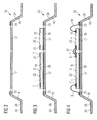
- FIG 11 shows a schematic cross section through a Semiconductor module 25 according to a fifth embodiment of Invention.
- This fifth embodiment of the invention has the same components as the embodiment of FIG 12 according to the prior art, however, in these are Components down to the sensitive area of the sensor chip 1 covered by the non-transparent plastic housing material 8.
- an opening 9 in the form of a Laserabtragstrichters 12 above the sensitive area 7 of the sensor chip 1 remain the remaining non-sensitive areas and Components 16 of the semiconductor module 25 through the plastic housing composition 8 from mechanical damage and thermomechanical Tensions protected.
Abstract
Description
- Figur 1
- zeigt einen schematischen Querschnitt durch ein Halbleitermodul gemäß einer ersten Ausführungsform der Erfindung;
- Figuren 2 bis 7
- zeigen schematische Querschnitte von Komponenten im Rahmen der Herstellung eines Halbleitermoduls gemäß Figur 1;
- Figur 2
- zeigt einen schematischen Querschnitt einer Halbleitermodulposition eines Flachleiterrahmens;
- Figur 3
- zeigt einen schematischen Querschnitt der Halbleitermodulposition gemäß Figur 1 nach Aufbringen von Halbleiterchips bzw. nach Aufbringen von Komponenten;
- Figur 4
- zeigt einen schematischen Querschnitt durch eine Halbleitermodulposition gemäß Figur 3 nach Aufbringen von Bonddrahtverbindungen;
- Figur 5
- zeigt einen schematischen Querschnitt der Halbleitermodulposition gemäß Figur 4 nach Aufbringen einer nicht transparenten Kunststoffgehäusemasse;
- Figur 6
- zeigt einen schematischen Querschnitt der Halbleitermodulposition gemäß Figur 5 während eines Laserabtrages;
- Figur 7
- zeigt einen schematischen Querschnitt der Halbleitermodulposition gemäß Figur 6 nach Freilegen des Sensorbereichs des Halbleitersensorchips;
- Figur 8
- zeigt einen schematischen Querschnitt durch ein Halbleitermodul gemäß einer zweiten Ausführungsform der Erfindung;
- Figur 9
- zeigt einen schematischen Querschnitt durch ein Halbleitermodul gemäß einer dritten Ausführungsform der Erfindung;
- Figur 10
- zeigt einen schematischen Querschnitt durch ein Halbleitermodul gemäß einer vierten Ausführungsform der Erfindung;
- Figur 11
- zeigt einen schematischen Querschnitt durch ein Halbleitermodul gemäß einer fünften Ausführungsform der Erfindung;
- Figur 12
- zeigt einen schematischen Querschnitt durch ein Halbleitermodul gemäß dem Stand der Technik.
- 1
- (Halbleiter) -Sensorchip
- 2
- Gehäuse
- 3
- Sensorbereich
- 4
- weitere Komponente des Halbleitermoduls
- 5
- Halbleitermodul (1. Ausführungsform)
- 6
- elektrische Verbindung
- 7
- nicht sensitive Bereiche des Sensorchips
- 8
- nicht transparente Kunststoffgehäusemasse
- 9
- Öffnung
- 10
- Halbleitermodul (2. Ausführungsform)
- 11
- Umgebung
- 12
- Laserabtragstrichter
- 13
- transparentes Material
- 14
- gummielastisches und transparentes Material
- 15
- Halbleitermodul (3. Ausführungsform)
- 16
- Komponenten des Halbleitermoduls beispielsweise Chips, wie Sensorchips Halbleiterchips und/oder passive Bauelemente
- 17
- Chipinsel
- 18
- innerer Flachleiter
- 19
- Bonddrahtverbindung
- 20
- Halbleitermodul (4. Ausführungsform)
- 21
- Kontaktflächen
- 22
- aktive Oberseite der Chips
- 23
- Kontaktanschlussflächen
- 24
- Außenflachleiter
- 25
- Halbleitermodul (5. Ausführungsform)
- 26
- Außenkontakt
- 27
- Lasergerät
- 28
- Spiegeltrommel
- 29
- polygonaler Querschnitt
- 30
- Halbleitermodul (Stand der Technik)
- 31
- Längsachse
- 32
- Hochachse
- 33
- Halbleitermodulposition
- 34
- Flachleiterrahmen
- 35
- Lotschicht
- 36
- Rückseite der Halbleiterchips
- 37
- Bondverbindung von Halbleiterchip zu Halbleiterchip
- 38
- Laserstrahl
- 39
- Laserstrahlbereich
- 40
- Kavität
- 41
- Stützer
- A
- Pfeilrichtung
- B
- Pfeilrichtung
Claims (18)
- Halbleitermodul mit einem Halbleiter-Sensorchip (1) und einem Gehäuse (2), wobei der Sensorchip (1) einen Sensorbereich (3) aufweist und mit mindestens einer weiteren Komponente (4) des Halbleitermoduls (5) über elektrische Verbindungen (6) in weiterverbindung steht, wobei vom Sensorchip (1) die nicht sensitiven Bereiche (7) und die weitere Komponente (4) sowie die elektrischen Verbindungen (6) in einer nicht transparenten Kunststoffgehäusemasse (8) eingebettet sind und der Sensorbereich (3) des Sensorchips (1) über eine Öffnung (9) in der nicht transparenten Kunststoffgehäusemasse (8) mit der Umgebung (11) in Wirkverbindung steht, wobei die Öffnung (9) einen Laserabtragstrichter (12) aufweist.
- Halbleitermodul nach Anspruch 1,
dadurch gekennzeichnet, dass
das der Laserabtragstrichter (12) mit einem transparenten Material (13) teilweise aufgefüllt ist. - Halbleitermodul nach Anspruch 1 oder nach Anspruch 2,
dadurch gekennzeichnet, dass
das der Laserabtragstrichter (12) mit einem gummielastischen und transparentem Material (14) teilweise aufgefüllt ist. - Halbleitermodul nach einem der vorhergehenden Ansprüche,
dadurch gekennzeichnet, dass
die Komponenten (16) stoffschlüssig auf Chipinseln (17) von inneren Flachleitern (18) fixiert sind. - Halbleitermodul nach einem der Ansprüche 1 bis 3,
dadurch gekennzeichnet, dass
die Komponenten (16) stoffschlüssig auf Chipinseln (17) eines Verdrahtungssubstrats eines BGA- oder LGA-Gehäuses fixiert sind. - Halbleitermodul nach Anspruch 4 oder Anspruch 5,
dadurch gekennzeichnet, dass
die elektrischen Verbindungen (6) Bonddrahtverbindungen (19) aufweisen, welche Kontaktflächen (21) der aktiven Oberseiten (22) der Chips (16) mit Kontaktanschlussflächen (23) auf den inneren Flachleitern (18) oder auf dem Verdrahtungssubstrat verbinden. - Halbleitermodul nach Anspruch 4 oder Anspruch 6,
dadurch gekennzeichnet, dass
die inneren Flachleiter (18) als Außenflachleiter (24) aus der Kunststoffgehäusemasse (8) herausragen. - Halbleitermodul nach Anspruch 5 oder Anspruch 6,
dadurch gekennzeichnet, dass
das Verdrahtungssubstrat auf seiner Oberseite die Komponenten (16) aufweist und auf seiner Unterseite Lotbälle als Außenkontakte besitzt. - Halbleitermodul nach einem der Ansprüche 1 bis 8,
dadurch gekennzeichnet, dass
das Halbleitermodul (5) als stoffschlüssige Verbindung der Komponenten (16) eine eutektische Lötverbindung aufweist. - Halbleitermodul nach einem der Ansprüche 1 bis 8,
dadurch gekennzeichnet, dass
das Halbleitermodul (5) als stoffschlüssige Verbindung der Komponenten (16) eine Diffusionslötverbindung aufweist. - Halbleitermodul nach einem der Ansprüche 1 bis 8,
dadurch gekennzeichnet, dass
das Halbleitermodul (5) als stoffschlüssige Verbindung der Komponenten (16) eine Lotpastenverbindung aufweist. - Verwendung des Halbleitermoduls (5) gemäss einem der vorhergehenden Ansprüche, als optischen Sensor und/oder optischen Empfänger in der KFZ-Technik.
- Verwendung des Halbleitermoduls (5) gemäss einem der vorhergehenden Ansprüche, als optischen Sensor und/oder optischen Empfänger in einem Glasfaserkabelbaum von KFZ' s.
- Verwendung des Halbleitermoduls (5) gemäss einem der vorhergehenden Ansprüche, als Druck- oder Temperatursensor in der KFZ-Technik.
- Verfahren zur Herstellung eines Halbleitermoduls (5) mit einem Halbleiter-Sensorchip (1) und einem Gehäuse (2), wobei das Verfahren folgende Verfahrensschritte aufweist:Herstellen eines Systemträgers mit Halbleitermodulposition (33) und Kontaktanschlussflächen (23) für elektrische Verbindungen (6) zu Außenkontakten (26) für mindestens ein Halbleitermodul (5),Aufbringen von einem Halbleiter-Sensorchip (1) mit einem Sensorbereich (3) und mindestens einer weiteren Komponenten (4) des Halbleitermoduls (5) auf den Systemträger unter stoffschlüssigem Verbinden der Komponenten (16) mit dem Systemträger,Herstellen von elektrischen Verbindungen zwischen Kontaktflächen (21) der Komponenten (16) und Kontaktanschlussflächen (23) des Systemträgers, sowie zwischen Kontaktflächen unterschiedlicher Chips (16),Aufbringen einer nicht transparenten Kunststoffgehäusemasse (8) auf den Systemträger, unter Einbetten der Komponenten (16) und der elektrischen Verbindungen (6) in der Kunststoffgehäusemasse (8),Freilegen des Sensorbereichs (3) des Halbleiter-Sensorchips (1) unter Bilden eines Laserabtragstrichters (12) zum Sensorbereich mittels Laserabtragstechnik.
- Verfahren nach Anspruch 15,
dadurch gekennzeichnet, dass
für einen Laserabtrag ein Lasergerät (27) und eine Spiegeltrommel (28) mit polygonalem Querschnitt (29) eingesetzt wird, wobei die Spiegeltrommel (28) um eine horizontale Längsachse (31) gedreht wird, während das Lasergerät (27) oder ein Planspiegel im Laserstrahl (38) um eine Hochachse (32) geschwenkt wird, um den Laserstrahl entlang der Spiegeltrommellängserstreckung abzulenken, und um somit durch eine flächige Abtastung eine Öffnung (9) über dem Sensorbereich (3) herzustellen. - Verfahren nach Anspruch 15 oder Anspruch 16,
dadurch gekennzeichnet, dass
als Systemträger ein Nutzen eingesetzt wird. - Verfahren nach Anspruch 15 oder Anspruch 16,
dadurch gekennzeichnet, dass
als Systemträger ein Flachleiterrahmen (34) eingesetzt wird.
Applications Claiming Priority (2)
| Application Number | Priority Date | Filing Date | Title |
|---|---|---|---|
| DE200410027094 DE102004027094A1 (de) | 2004-06-02 | 2004-06-02 | Halbleitermodul mit einem Halbleiter-Sensorchip und einem Kunststoffgehäuse sowie Verfahren zu dessen Herstellung |
| DE102004027094 | 2004-06-02 |
Publications (2)
| Publication Number | Publication Date |
|---|---|
| EP1602625A1 true EP1602625A1 (de) | 2005-12-07 |
| EP1602625B1 EP1602625B1 (de) | 2007-12-05 |
Family
ID=34938462
Family Applications (1)
| Application Number | Title | Priority Date | Filing Date |
|---|---|---|---|
| EP20050090155 Expired - Fee Related EP1602625B1 (de) | 2004-06-02 | 2005-05-30 | Halbleitermodul mit einem Halbleiter-Sensorchip und einem Kunststoffgehäuse sowie Verfahren zu dessen Herstellung |
Country Status (3)
| Country | Link |
|---|---|
| US (1) | US20060001116A1 (de) |
| EP (1) | EP1602625B1 (de) |
| DE (2) | DE102004027094A1 (de) |
Cited By (2)
| Publication number | Priority date | Publication date | Assignee | Title |
|---|---|---|---|---|
| US8618620B2 (en) | 2010-07-13 | 2013-12-31 | Infineon Technologies Ag | Pressure sensor package systems and methods |
| CN113460947A (zh) * | 2020-03-30 | 2021-10-01 | 英飞凌科技股份有限公司 | 传感器封装件和用于制造传感器封装件的方法 |
Families Citing this family (26)
| Publication number | Priority date | Publication date | Assignee | Title |
|---|---|---|---|---|
| DE102005006280B4 (de) * | 2005-02-10 | 2006-11-16 | Infineon Technologies Ag | Halbleiterbauteil mit einem Durchkontakt durch eine Gehäusemasse und Verfahren zur Herstellung desselben |
| DE102007005630B4 (de) * | 2007-02-05 | 2019-08-08 | Infineon Technologies Ag | Sensorchip-Modul und Verfahren zur Herstellung eines Sensorchip-Moduls |
| JP2009099680A (ja) * | 2007-10-15 | 2009-05-07 | Panasonic Corp | 光学デバイスおよびその製造方法 |
| EP2051298B1 (de) * | 2007-10-18 | 2012-09-19 | Sencio B.V. | Gehäuse mit integrierter Schaltung |
| EP2090873B1 (de) * | 2008-02-14 | 2011-06-01 | Elmos Advanced Packaging B.V. | Integriertes Schaltungsgehäuse |
| DE102008000889B4 (de) | 2008-03-31 | 2022-10-27 | Robert Bosch Gmbh | Wegbausensor und Verfahren zur Herstellung eines Wegbausensors mittels Einlegen und kraft-/formschlüssiger Verbindung |
| CN101364585B (zh) * | 2008-09-25 | 2010-10-13 | 旭丽电子(广州)有限公司 | 一种芯片封装结构及其制造方法 |
| WO2010113712A1 (ja) * | 2009-03-31 | 2010-10-07 | アルプス電気株式会社 | 容量型湿度センサ及びその製造方法 |
| WO2011015642A1 (de) | 2009-08-05 | 2011-02-10 | Continental Teves Ag & Co. Ohg | Sensoranordnung und chip mit zusätzlichen befestigungsbeinen |
| US8350381B2 (en) * | 2010-04-01 | 2013-01-08 | Infineon Technologies Ag | Device and method for manufacturing a device |
| DE102010046966B4 (de) | 2010-09-29 | 2018-05-24 | Infineon Technologies Ag | Baustein und Verfahren zur Herstellung eines Bausteins |
| JP5333529B2 (ja) * | 2011-07-05 | 2013-11-06 | 株式会社デンソー | モールドパッケージの製造方法 |
| US8842951B2 (en) | 2012-03-02 | 2014-09-23 | Analog Devices, Inc. | Systems and methods for passive alignment of opto-electronic components |
| US9716193B2 (en) | 2012-05-02 | 2017-07-25 | Analog Devices, Inc. | Integrated optical sensor module |
| US20140312450A1 (en) * | 2013-04-23 | 2014-10-23 | Sensors Unlimited, Inc. | Small Size, Weight, and Packaging of Image Sensors |
| DE102014000243B4 (de) | 2013-04-29 | 2015-06-25 | Elmos Semiconductor Aktiengesellschaft | MEMS Sensor für schwierige Umgebungen und Medien |
| US10884551B2 (en) | 2013-05-16 | 2021-01-05 | Analog Devices, Inc. | Integrated gesture sensor module |
| US9448130B2 (en) * | 2013-08-31 | 2016-09-20 | Infineon Technologies Ag | Sensor arrangement |
| CN104426995A (zh) * | 2013-09-11 | 2015-03-18 | 腾讯科技(深圳)有限公司 | 核心组件、终端设备、服务器、系统及服务提供方法 |
| US9910145B2 (en) * | 2013-12-19 | 2018-03-06 | Infineon Technologies Ag | Wireless communication system, a radar system and a method for determining a position information of an object |
| CN108689382A (zh) * | 2014-05-30 | 2018-10-23 | 日月光半导体制造股份有限公司 | 微机电感测装置封装结构及制造工艺 |
| US9590129B2 (en) | 2014-11-19 | 2017-03-07 | Analog Devices Global | Optical sensor module |
| US9446941B2 (en) | 2014-12-12 | 2016-09-20 | Apple Inc. | Method of lower profile MEMS package with stress isolations |
| US10336606B2 (en) * | 2016-02-25 | 2019-07-02 | Nxp Usa, Inc. | Integrated capacitive humidity sensor |
| US10712197B2 (en) | 2018-01-11 | 2020-07-14 | Analog Devices Global Unlimited Company | Optical sensor package |
| NL2020901B1 (en) * | 2018-05-09 | 2019-11-18 | Sencio B V | A sensor package and a method of manufacturing a sensor package |
Citations (5)
| Publication number | Priority date | Publication date | Assignee | Title |
|---|---|---|---|---|
| DE19640255A1 (de) * | 1996-09-30 | 1998-04-02 | Siemens Ag | Verfahren zur Herstellung eines elektronischen Moduls mit einem kunststoffumspritzten Leadframe |
| DE19754616A1 (de) * | 1996-12-09 | 1998-06-10 | Denso Corp | Halbleitersensorbauelement |
| DE10208635A1 (de) * | 2002-02-28 | 2003-09-18 | Infineon Technologies Ag | Diffusionslotstelle und Verfahren zu ihrer Herstellung |
| US6624921B1 (en) * | 2001-03-12 | 2003-09-23 | Amkor Technology, Inc. | Micromirror device package fabrication method |
| DE10246283B3 (de) * | 2002-10-02 | 2004-03-25 | Infineon Technologies Ag | Verfahren zur Herstellung von Kanälen und Kavitäten in Halbleitergehäusen und elektronisches Bauteil mit derartigen Kanälen und Kavitäten |
Family Cites Families (8)
| Publication number | Priority date | Publication date | Assignee | Title |
|---|---|---|---|---|
| US5438216A (en) * | 1992-08-31 | 1995-08-01 | Motorola, Inc. | Light erasable multichip module |
| JP3171176B2 (ja) * | 1998-12-15 | 2001-05-28 | 日本電気株式会社 | 半導体装置およびボール・グリッド・アレイ製造方法 |
| DE10029269B4 (de) * | 2000-06-14 | 2005-10-13 | Infineon Technologies Ag | Verfahren zur Herstellung eines elektronischen Bauteiles aus gehäusebildenden Substraten |
| EP1246235A1 (de) * | 2001-03-26 | 2002-10-02 | European Semiconductor Assembly (Eurasem) B.V. | Verfahren zum Einkapseln eines Chips mit empfindlicher Oberfläche |
| US7060216B2 (en) * | 2001-05-11 | 2006-06-13 | Melexis, Nv | Tire pressure sensors and methods of making the same |
| US6762077B2 (en) * | 2001-05-11 | 2004-07-13 | Melexis Nv | Integrated sensor packages and methods of making the same |
| DE10205127A1 (de) * | 2002-02-07 | 2003-08-28 | Infineon Technologies Ag | Halbleiterbauteil mit Sensor- bzw. Aktoroberfläche und Verfahren zu seiner Herstellung |
| DE10330739A1 (de) * | 2003-07-07 | 2004-09-23 | Infineon Technologies Ag | Mikroelektromechanisches Modul mit Sensor und Gehäuse sowie Verfahren zur Herstellung derselben |
-
2004
- 2004-06-02 DE DE200410027094 patent/DE102004027094A1/de not_active Ceased
-
2005
- 2005-05-30 EP EP20050090155 patent/EP1602625B1/de not_active Expired - Fee Related
- 2005-05-30 DE DE200550002131 patent/DE502005002131D1/de not_active Expired - Fee Related
- 2005-06-02 US US11/143,206 patent/US20060001116A1/en not_active Abandoned
Patent Citations (5)
| Publication number | Priority date | Publication date | Assignee | Title |
|---|---|---|---|---|
| DE19640255A1 (de) * | 1996-09-30 | 1998-04-02 | Siemens Ag | Verfahren zur Herstellung eines elektronischen Moduls mit einem kunststoffumspritzten Leadframe |
| DE19754616A1 (de) * | 1996-12-09 | 1998-06-10 | Denso Corp | Halbleitersensorbauelement |
| US6624921B1 (en) * | 2001-03-12 | 2003-09-23 | Amkor Technology, Inc. | Micromirror device package fabrication method |
| DE10208635A1 (de) * | 2002-02-28 | 2003-09-18 | Infineon Technologies Ag | Diffusionslotstelle und Verfahren zu ihrer Herstellung |
| DE10246283B3 (de) * | 2002-10-02 | 2004-03-25 | Infineon Technologies Ag | Verfahren zur Herstellung von Kanälen und Kavitäten in Halbleitergehäusen und elektronisches Bauteil mit derartigen Kanälen und Kavitäten |
Non-Patent Citations (1)
| Title |
|---|
| BUTLER J T ET AL: "EXTENSION OF HIGH DENSITY INTERCONNECT MULTICHIP MODULE TECHNOLOGY FOR MEMS PACKAGING", PROCEEDINGS OF THE SPIE, SPIE, BELLINGHAM, VA, US, vol. 3224, 29 September 1997 (1997-09-29), pages 169 - 177, XP009014670, ISSN: 0277-786X * |
Cited By (3)
| Publication number | Priority date | Publication date | Assignee | Title |
|---|---|---|---|---|
| US8618620B2 (en) | 2010-07-13 | 2013-12-31 | Infineon Technologies Ag | Pressure sensor package systems and methods |
| US11192777B2 (en) | 2010-07-13 | 2021-12-07 | Infineon Technologies Ag | MEMS sensor package systems and methods |
| CN113460947A (zh) * | 2020-03-30 | 2021-10-01 | 英飞凌科技股份有限公司 | 传感器封装件和用于制造传感器封装件的方法 |
Also Published As
| Publication number | Publication date |
|---|---|
| DE502005002131D1 (de) | 2008-01-17 |
| EP1602625B1 (de) | 2007-12-05 |
| DE102004027094A1 (de) | 2005-12-29 |
| US20060001116A1 (en) | 2006-01-05 |
Similar Documents
| Publication | Publication Date | Title |
|---|---|---|
| EP1602625B1 (de) | Halbleitermodul mit einem Halbleiter-Sensorchip und einem Kunststoffgehäuse sowie Verfahren zu dessen Herstellung | |
| DE10246283B3 (de) | Verfahren zur Herstellung von Kanälen und Kavitäten in Halbleitergehäusen und elektronisches Bauteil mit derartigen Kanälen und Kavitäten | |
| EP1380056B2 (de) | Optoelektronische bauelementanordnung und verfahren zur herstellung einer optoelektronischen bauelementanordnung | |
| DE10259221B4 (de) | Elektronisches Bauteil mit einem Stapel aus Halbleiterchips und Verfahren zur Herstellung desselben | |
| DE19518753B4 (de) | Halbleitervorrichtung und Verfahren zu ihrer Herstellung | |
| DE10049288B4 (de) | Elektronische Bauteile und eine Folienband zum Verpacken von Bonddrahtverbindungen elektronischer Bauteile sowie deren Herstellungsverfahren | |
| EP1917509A1 (de) | Sensoranordnung mit einem substrat und mit einem gehäuse und verfahren zur herstellung einer sensoranordnung | |
| DE19929754C2 (de) | Verguß einer bestückten Baugruppe mit vibrationsdämpfender Gießmasse | |
| DE102011003195B4 (de) | Bauteil und Verfahren zum Herstellen eines Bauteils | |
| DE3022840A1 (de) | Gekapselte schaltungsanordnung und verfahren zu ihrer herstellung | |
| EP1472727A2 (de) | Halbleiterbauteil mit sensor- bzw. aktoroberfläche und verfahren zu seiner herstellung | |
| DE102004011203A1 (de) | Verfahren zum Montieren von Halbleiterchips und entsprechende Halbleiterchipanordnung | |
| DE19717611A1 (de) | Struktur zum Anbringen von elektronischen Komponenten und Verfahren zum Anbringen der elektronischen Komponenten | |
| DE102006056361B4 (de) | Modul mit polymerhaltigem elektrischen Verbindungselement und Verfahren | |
| DE3810899C2 (de) | ||
| DE102010030960A1 (de) | Verfahren zur Herstellung eines schwingungsgedämpften Bauteils | |
| EP2379998A1 (de) | Vorrichtung und verfahren zur herstellung einer vorrichtung | |
| DE10232788B4 (de) | Elektronisches Bauteil mit einem Halbleiterchip auf einem Systemträger, Systemträger und Verfahren zur Herstellung eines elektronischen Bauteils | |
| DE102006026023A1 (de) | Halbleiterbauteil mit Halbleiterchipstapel und Kunststoffgehäuse sowie Verfahren zur Herstellung des Halbleiterbauteils | |
| EP1595287B1 (de) | Elektronisches bauteil mit halbleiterchip und verfahren zur herstellung desselben | |
| DE10161936A1 (de) | Elektroniksteuereinheit | |
| DE60006365T2 (de) | Akustische oberflächenwellenanordnung verbunden mit einem sockel durch einen leitenden klebstoff | |
| DE102010001759B4 (de) | Mikromechanisches System und Verfahren zum Herstellen eines mikromechanischen Systems | |
| DE102009029281A1 (de) | Modul und Verfahren zur Herstellung eines Moduls | |
| DE102007057904A1 (de) | Sensormodul und Verfahren zur Herstellung des Sensormoduls |
Legal Events
| Date | Code | Title | Description |
|---|---|---|---|
| PUAI | Public reference made under article 153(3) epc to a published international application that has entered the european phase |
Free format text: ORIGINAL CODE: 0009012 |
|
| AK | Designated contracting states |
Kind code of ref document: A1 Designated state(s): AT BE BG CH CY CZ DE DK EE ES FI FR GB GR HU IE IS IT LI LT LU MC NL PL PT RO SE SI SK TR |
|
| AX | Request for extension of the european patent |
Extension state: AL BA HR LV MK YU |
|
| 17P | Request for examination filed |
Effective date: 20051027 |
|
| AKX | Designation fees paid |
Designated state(s): DE FR GB |
|
| 17Q | First examination report despatched |
Effective date: 20060328 |
|
| GRAP | Despatch of communication of intention to grant a patent |
Free format text: ORIGINAL CODE: EPIDOSNIGR1 |
|
| GRAS | Grant fee paid |
Free format text: ORIGINAL CODE: EPIDOSNIGR3 |
|
| GRAA | (expected) grant |
Free format text: ORIGINAL CODE: 0009210 |
|
| AK | Designated contracting states |
Kind code of ref document: B1 Designated state(s): DE FR GB |
|
| REG | Reference to a national code |
Ref country code: GB Ref legal event code: FG4D Free format text: NOT ENGLISH |
|
| REF | Corresponds to: |
Ref document number: 502005002131 Country of ref document: DE Date of ref document: 20080117 Kind code of ref document: P |
|
| RAP2 | Party data changed (patent owner data changed or rights of a patent transferred) |
Owner name: AVAGO TECHNOLOGIES FIBER IP (SINGAPORE) PTE. LTD. |
|
| GBT | Gb: translation of ep patent filed (gb section 77(6)(a)/1977) |
Effective date: 20080312 |
|
| REG | Reference to a national code |
Ref country code: GB Ref legal event code: 732E |
|
| PGFP | Annual fee paid to national office [announced via postgrant information from national office to epo] |
Ref country code: DE Payment date: 20080605 Year of fee payment: 4 |
|
| EN | Fr: translation not filed | ||
| PLBE | No opposition filed within time limit |
Free format text: ORIGINAL CODE: 0009261 |
|
| STAA | Information on the status of an ep patent application or granted ep patent |
Free format text: STATUS: NO OPPOSITION FILED WITHIN TIME LIMIT |
|
| 26N | No opposition filed |
Effective date: 20080908 |
|
| PG25 | Lapsed in a contracting state [announced via postgrant information from national office to epo] |
Ref country code: FR Free format text: LAPSE BECAUSE OF FAILURE TO SUBMIT A TRANSLATION OF THE DESCRIPTION OR TO PAY THE FEE WITHIN THE PRESCRIBED TIME-LIMIT Effective date: 20081003 |
|
| GBPC | Gb: european patent ceased through non-payment of renewal fee |
Effective date: 20090530 |
|
| PG25 | Lapsed in a contracting state [announced via postgrant information from national office to epo] |
Ref country code: GB Free format text: LAPSE BECAUSE OF NON-PAYMENT OF DUE FEES Effective date: 20090530 |
|
| PG25 | Lapsed in a contracting state [announced via postgrant information from national office to epo] |
Ref country code: DE Free format text: LAPSE BECAUSE OF NON-PAYMENT OF DUE FEES Effective date: 20091201 |