EP1605233A1 - Driving support system and driving support method - Google Patents
Driving support system and driving support method Download PDFInfo
- Publication number
- EP1605233A1 EP1605233A1 EP05012247A EP05012247A EP1605233A1 EP 1605233 A1 EP1605233 A1 EP 1605233A1 EP 05012247 A EP05012247 A EP 05012247A EP 05012247 A EP05012247 A EP 05012247A EP 1605233 A1 EP1605233 A1 EP 1605233A1
- Authority
- EP
- European Patent Office
- Prior art keywords
- point information
- display
- point
- vehicle
- points
- Prior art date
- Legal status (The legal status is an assumption and is not a legal conclusion. Google has not performed a legal analysis and makes no representation as to the accuracy of the status listed.)
- Granted
Links
Images


Classifications
-
- G—PHYSICS
- G08—SIGNALLING
- G08G—TRAFFIC CONTROL SYSTEMS
- G08G1/00—Traffic control systems for road vehicles
- G08G1/09—Arrangements for giving variable traffic instructions
- G08G1/0962—Arrangements for giving variable traffic instructions having an indicator mounted inside the vehicle, e.g. giving voice messages
- G08G1/0967—Systems involving transmission of highway information, e.g. weather, speed limits
- G08G1/096766—Systems involving transmission of highway information, e.g. weather, speed limits where the system is characterised by the origin of the information transmission
- G08G1/096783—Systems involving transmission of highway information, e.g. weather, speed limits where the system is characterised by the origin of the information transmission where the origin of the information is a roadside individual element
-
- G—PHYSICS
- G01—MEASURING; TESTING
- G01C—MEASURING DISTANCES, LEVELS OR BEARINGS; SURVEYING; NAVIGATION; GYROSCOPIC INSTRUMENTS; PHOTOGRAMMETRY OR VIDEOGRAMMETRY
- G01C21/00—Navigation; Navigational instruments not provided for in groups G01C1/00 - G01C19/00
- G01C21/26—Navigation; Navigational instruments not provided for in groups G01C1/00 - G01C19/00 specially adapted for navigation in a road network
- G01C21/34—Route searching; Route guidance
- G01C21/36—Input/output arrangements for on-board computers
Definitions
- the present invention relates to a driving support system and a driving support method that allow a display device to display information related to points on a route of a vehicle for thereby supporting a driver.
- Japanese Patent Application Laid-open Publication No. 9-189565 discloses a technology to have information on the route, such as a curve direction, a curvature, a curve length and a gradient angle of curve points located thereon, displayed on a liquid crystal display of a navigation system, using coordinates data of map information utilized in the navigation system.
- Japanese Patent Application Laid-open Publication No. 9-34352 discloses a head-up display device for car navigation, which provides a display of a guiding figure superimposed on a view of a road at a passing point, and when a distance to the passing point is large, the guiding figure is temporarily enlarged in accordance with the magnification set by the distance.
- the information related to the points on the route are displayed on a predetermined area of the display device with no provision of the display associated with directions in which the points are actually located. Therefore , the driver' s view through a windshield cannot be coordinated with the information displayed on the display device, resulting in a difficulty for the driver to intuitively and quickly recognize the information.
- the present invention has been made in the light of the problem. It is an object of the present invention is to provide a driving support system and a driving support method which presents information related to points on a route of a vehicle to the driver in a manner that the driver can intuitively and quickly recognize the information coordinated with a driver's view through a windshield, thereby supporting the driver's operation.
- An aspect of the present invention is a driving support system comprising: a vehicle location detector which detects current location and velocity vector of a vehicle; a traffic and road information database which stores at least point information related to points on a route of the vehicle; a point information acquisition unit which acquires, from the traffic and road information database, the point information of the points on the route of the vehicle, which are located in a given distance from the current location of the vehicle and to which the vehicle is approaching, based on the current location and velocity vector of the vehicle detected by the vehicle location detector; a display device having a horizontally long screen in a lower area of a windshield of the vehicle, which provides on the screen thereof displays of the point information acquired by the point information acquisition unit; and a display control unit for controlling the display device, wherein the display control unit determines display positions on the screen of the display device to display the point information, based on a positional relationship between the current location of the vehicle and the points where the point information related thereto are displayed.
- Another aspect of the present invention is a driving support method for providing a driver with information related to points on a route, comprising: detecting a current location and velocity vector of a vehicle; acquiring point information related to points on a route of the vehicle, which are located in a given distance from a current location of the vehicle and to which the vehicle is approaching, based on the detected current location and velocity vector of the vehicle; and displaying the acquired point information on a horizontally long screen of a display device, disposed in a lower area of a windshield of the vehicle, wherein display positions of the point information on the screen of the display device are determined based on a positional relationship between the current location of the vehicle and the points where the point information related thereto are displayed, while image sizes of the point information to be displayed are determined based on distances from the current location of the vehicle to the points where the point information related thereto are displayed.
- FIG. 1 is a block diagram showing configuration of a driving support system SS1 according to a first embodiment of the present invention.
- the driving support system SS1 is installed on a vehicle (with a vehicle installed with the present system being referred to as a host vehicle) to allow a display device 1 to display point information related to a point on a route of the vehicle for thereby supporting a driver thereof, and includes, in addition to the display device 1, a vehicle location detector 2, a traffic and road information database 3, a point information acquisition unit 4, and a display control unit 5.
- the display device 1 is comprised of a display unit, such as a liquid crystal display, which has a horizontally long screen located at a lower area of a windshield.
- the display device 1 provides a display of point information related to the point on the route, in a pattern coordinated with a driver's view through a windshield under control of the display control unit 5.
- the display device 1 a variety of display devices may be applied, each of which is able to ensure a display area Da in a horizontally long shape along the windshield.
- an organic EL (electroluminescence) panel and a HUD (Heads Up Display) may be listed up.
- the vehicle location detector 2 serves to detect a current location G (in latitude and longitude) and a velocity vector (speed and direction) Gv of the host vehicle A using a GPS (Global Positioning System) and an autonomous sensor.
- a GPS Global Positioning System
- an autonomous sensor As for the vehicle location detector 2, those in a generally used on-vehicle navigation system can be utilized to find the current location G and the velocity vector Gv of the host vehicle A on a real time basis (to update information for each 5Hz) during running.
- the traffic and road information database 3 serves to store road information including road shape information indicative of a road shape, and point information that forms information specific for each latitude and longitude.
- road shape information is a set of vector data representing road shape with points (nodes and interpolation points) and line segments (links), and each node and interpolation point are provided with information on the latitude and longitude thereof and road curvature information R as attribute data thereof.
- Each link is provided with a road category, a road width and basic advisory speed information of a road represented by the link as attribute data. Further, as shown in FIG.
- point information has the form of a structured data associated with information on the latitude and longitude indicative of a location coordinates on the relevant point Pn provided by information (a curvature and slope angle of the relevant point, an advisory speed when passing the relevant point, a speed limit, a surface resistance, a presence or absence of an impedimenta, a road construction and a traffic accident, and a tail end of a traffic jam) specific to each point Pn.
- Point information on each point Pn is provided with information such as a typical icon representing a priority of the relevant information and related point.
- FIG. 2 shows an example of point information related to points P1, P2, P3 forming curve points, respectively, in which advisory speed information are exemplarily indicated as information specific for respective points.
- Road information including road shape information and point information is provided, using map data generally used in the on-vehicle navigation system, to be stored in the traffic and road information database 3.
- the traffic and road information database 3 does not always have to be installed on the host vehicle A, and may be realized on an information providing server located in a remote place accessible using a communication device, such as a portable phone, a wireless LAN and a DSRC (Dedicated Short Range Communication), so as to allow the information providing server to be accessed from the host vehicle A for acquiring road information.
- a communication device such as a portable phone, a wireless LAN and a DSRC (Dedicated Short Range Communication)
- the point information acquisition unit 4 serves to execute map matching operation with the road information stored in the traffic and road information database 3, based on the current location G and the velocity vector Gv of the host vehicle A detected by the vehicle location detector 2, thereby specifying a location of the host vehicle A on a road, and acquiring road shape information of the road within a given distance LR from the current location of the host vehicle A and point information related to the point Pn located within the given distance LR from the current location of the host vehicle A.
- the given distance LR may be set to a distance available to obtain a number of point information optimum for driving operation or to a fixed value (of 500m, for example) determined upon preliminary experiments, or to a value varying depending on the road category and running speed of the host vehicle A.
- the display control unit 5 serves to control the display device 1 in a way to display point information, acquired by the point information acquisition unit, on a horizontally long screen Sc of the display device 1 disposed in the lower area of the windshield, in the pattern coordinated with the driver's view through the windshield, and has a function to determine a image size Iwn of the point information, a function to determine a display color of the point information and a function to determine a display position to display point information.
- the display control unit 5 calculates the distance Ln (the distances L1, L2, L3 from the points P1, P2, P3 in an example shown in FIG. 3) from the points Pn where the point information related thereto are displayed (hereinafter referred to as display points Pn), to the current location G of the host vehicle A as shown in FIG. 3.
- display points Pn the points Pn where the point information related thereto are displayed
- a drive distance to the display point Pn along the route calculated based on road shape information acquired by the point information acquisition unit 4 is herein described as an example of distance Ln from the current location G of the host vehicle A to the relevant point Pn
- an alternative may be a linear distance between the current location G of the host vehicle A and the relevant point Pn.
- the display control unit 5 determines an image size (a width or a surface area) Iwn for the point information, such that the closer the point Pn of the displayed point information is to the current location G of the host vehicle A, the larger will be the image size of the point information to be displayed on the screen Sc of the display device 1.
- the image size Iwn determined herein is less than a given value, it is hard for the driver to check what is displayed even if point information such as the advisory speed is displayed. In such a case, it is determined to display only the representative icon.
- the display control unit 5 determines display colors of relevant point information, such as red color for point information with a high priority Ipn, yellow color for point information with a middle priority and blue color for point information with a low priority, depending on the information priority Ipn of point information related to the relevant point Pn.
- This color-coding may also be applied to display contents per se or contours of frames surrounding the respective display contents.
- the display control unit 5 may be configured to calculate a deceleration ⁇ at which the host vehicle A is required to have its running speed decelerated to the advisory speed Vc for the display point Pn before the host vehicle A reaches the relevant point Pn, based on a current running speed Vi of the host vehicle A and the distance Ln to the relevant point Pn.
- the information priority Ipn may be determined in three levels such as high, middle and low priorities depending on the required deceleration ⁇ .
- the operation may be executed to calculate a display color for point information related to the point Pn.
- the display color of point information is thus determined based on the information priority Ipn which is determined based on the required deceleration ⁇ , it becomes possible to determine the display color of point information based on priorities meeting the needs of practical drives.
- the display control unit 5 calculates direction vectors Vn (V1, V2 , V3 in an example shown in FIG. 3) from the current location G of the host vehicle A to the relevant point Pn, and calculates direction vector angles ⁇ n ( ⁇ 1, ⁇ 2, ⁇ 3 in an example shown in FIG. 5) of the direction vectors Vn with respect to the velocity vector Gv of the host vehicle A.
- the display control unit 5 estimates directions, in which the display points Pn are actually located, on the basis of a driver's eye position Pd in the host vehicle A to determine positions on the screen Sc of the display device 1 in the relevant directions as display positions for the point information in a lateral direction of the display device 1.
- the display control unit 5 calculates an angle (right end angle) ⁇ r, formed by a straight line passing through the driver's eye position Pd and Vc located in straight front of the driver's eye position Pd on the screen Sc, and another straight line passing through a right end Vr of a display area Da and the driver's eye position Pd, using a linear distance D1 from the driver's eye position Pd, preliminarily set for each vehicle, to the screen Sc of the display device 1, and the distance Lr from the point Vc to the right end Vr of the display area Da on the screen Sc.
- the display control unit 5 calculates an angle (left end angle) ⁇ 1, formed by a straight line passing through the driver's eye position Pd and the point Vc, and another straight line passing through the left end Vl of the display area Da and the driver's eye position Pd, using the linear distance D1 from the driver's eye position Pd to the screen Sc and the distance L1 from the point Vc located in straight front of the driver's eye position Pd on the screen Sc, to a left end Vl of the display area Da on the screen Sc.
- the display control unit 5 determines a position on the screen Sc of the display device 1, in a direction of the direction vector angle ⁇ n from the driver's eye position Pd, to be a display position in the lateral direction thereof of the point information related to the point Pn.
- the display control unit 5 determines a position in the vicinity of the right end Vr of the display area Da, when the direction vector angle ⁇ n is deviated rightward from the right end Vr of the display area Da, or a position in the vicinity of the left end Vl of the display area Da, when the direction vector angle ⁇ n is deviated leftward from the left end Vl of the display area Da, to be the display position for point information related to the point Pn.
- the display control unit 5 provides a display of point information in a display mode showing a direction, in which the relevant point Pn is actually located, is deviated from the range of the display area Da on the screen Sc of the display device 1 or a display of such information in combination with an icon indicating such notification.
- the display control unit 5 determines the display positions for the point information related to the points Pn in a vertical direction of the display area Da on the screen Sc of the display device 1, depending on the drive distances Ln from the current location G of the host vehicle A to the relevant points Pn. More particularly, the display control unit 5 determines a vertical offset Vpcn such that when a distance from a lower end of the display area Da to the image of the point information related to the point Pn is assigned to be the vertical offset Vpcn, as the point Pn of the point information is closer to the current location G of the host vehicle A, the point information is displayed at a lower area of the display area Da. Furthermore, on the contrary, the display control unit 5 may be arranged to determine the vertical offset Vpcn such that as the point Pn of the point information is closer to the current location G of the host vehicle A, point information is displayed at an upper area of the display area Da.
- point information is displayed on the display area Da at the lower area thereof, it becomes possible to perform a reliable coordination between an actual point Pn and point information related to such point Pn.
- point information is displayed on the display area Da at the upper area thereof, a situation results in which point information of the point Pn close proximity to the current location of the host vehicle A is displayed in a position close proximity to a focus point of the driver during driving.
- the display control unit 5 determines the image size Iwn, the display color and display position of point information related to the relevant point Pn in a manner as set forth above and depending on such contents, controls the display device 1 such that as shown in FIG. 8, point information related to the display point Pn displayed on the horizontally long screen Sc of the display device 1, disposed at the lower area of the windshield, in a pattern coordinated with the driver's view through the windshield. Also, a case shown in FIG. 8 indicates an example in which information on the advisory speed when passing the respective points are displayed on the screen Sc of the display device 1 as point information related to the points P1, P2, P3 shown in FIGS. 2, 3 and 5.
- the display control unit 5 determines the image size Iwn, the display color and the display position for these plural point information, respectively, to allow these point information tobe concurrently displayed at positions coordinated on the screen Sc of the display device 1. If plural point information are concurrently displayed, probabilities occur with the overlapping taking place in image of these point information and, in such a case, it becomes difficult for the driver to catch the display contents. Therefore, in cases where discrimination is made that the overlapping takes place in image of point information that are concurrently displayed, the display control unit 5 is operative to provide a display with a top priority on point information of the point closest to the current location G of the host vehicle A.
- the display control unit 5 is operative to select, among the plural points with the images of the point information thereof overlapping each other, a point closest to the current location G of the host vehicle A to allow point information related to such selected point to be displayed while avoiding a display of point information of the other non-selected points with the images of the point information thereof overlapping each other.
- point information of the other non-selected points may be displayed in a thinner color than that originally displayed.
- FIG. 9 A flow shown in FIG. 9 is repeatedly executed at a given frequency during running.
- step S1 the vehicle location detector 2 detects a current location G and a velocity vector Gv of a host vehicle A. Information on the current location G and the velocity vector Gv of the host vehicle A is delivered to the point information acquisition unit 4 and the display control unit 5.
- the point information acquisition unit 4 executes map matching operation with road information stored in the traffic and road information database 3 based on the current location G of the host vehicle A, detected by the vehicle location detector 2, and the velocity vector Gv, to specifyaroad, inwhichthehostvehicleAis located, and acquires road shape information within the given distance LR from the current location of the host vehicle A and point information on the points (display points) Pn located in the given distance LR on the specified road or a vicinity of the relevant road.
- Point information on the display points Pn acquired by the point information acquisition unit 4 are delivered to the display control unit 5.
- point information of the display point which has been treated as a target to be displayed in operation at the preceding cycle and which is also treated as a display point to be displayed in the current operation, may be utilized intact and no operation is executed to acquire new information.
- the display control unit 5 calculates a drive distance LR from the current location G of the host vehicle A to the display point Pn, based on the location coordinates of the current location G of the host vehicle A, the location coordinates of the display point Pn, and road shape information.
- next step S4 the display control unit 5 calculates a direction vector angle ⁇ n of the point Pn (an angle of the direction vector Vn of the display point Pn with respect to the velocity vector Gv) based on the velocity vector Gv of the host vehicle A, the location coordinates of the current location G of the host vehicle A and the location coordinates of the point Pn.
- direction angle ⁇ n of the point Pn is set such that the direction angle overlapping with the velocity vector Gv of the host vehicle lies at 0 degree with right side designated in a positive (+) value and the left side in a negative (-) value.
- the direction angles ( ⁇ 1, ⁇ 2, ⁇ 3) are calculated for these plural points, respectively.
- the display control unit 5 determines the image size Iwn for point information related to the display point Pn based on drive distance Ln calculated in step S3.
- the image size Iwn for point information represents a lateral width in case of a fixed aspect ratio and is determined such that in accordance with the relationship shown in FIG. 4, the longer the drive distance Ln, the smaller will be the image size Iwn whereas the shorter the drive distance Ln, the larger will be the image size Iwn. Accordingly, as the host vehicle A approaches to each point Pn, point information at this point Pn is displayed in a large size to be easily viewable.
- the image sizes (lw1, lw2, lw3) for point information are calculated for these pluralpoints,respectively. Also, as for point information, in which the image sizes Iwn determined herein are less than the given value, the display content is determined such that only representative icons added to relevant point information are displayed.
- next step S6 the display control unit 5 determines a display color of relevant point information depending on the priority Ipn, added to point information of the display point Pn, assigning red color for point information with a high priority, yellow color for point information with a middle priority and blue color for point information with a low priority. Also, when this takes place, if the content of point information to be displayed includes an advisory speed when passing the relevant point, the display control unit 5 calculates a required deceleration ⁇ using the current running speed V1 of the host vehicle A, the distance Ln to the point Pn and the advisory speed Vn at the point Pn.
- the display control unit 5 calculates a display position Vpn of point information (in a symbol "+” in a right direction and a symbol "-" in a left direction) in a lateral direction (x-axis direction in FIG. 10) on the display area centered at the point Vc in front of a driver, as shown in FIG.
- the point Vc located in front of a driver's eye position Pd on the screen Sc of the display device 1, the right end position Vr of the display area Dl on the screen Sc, the left end position Vl of the display area Da, the distance Dl between Pd-Vc, a distance between Vc-Vr, a distance between Vc-Vl , a direction vector angle ⁇ n of the display point Pn calculated in step S4, and a image size Iwn determined in step S5.
- the display point Pn includes the plural points (P1, P2, P3) as shown in FIG. 10
- display positions (Vp1, Vp2, Vp3) of point information are calculated for the plural display points, respectively.
- the display control unit 5 calculates a display position of point information (in terms of the vertically offset quantity Vpcn) in a vertical direction (along the y-axis in FIG. 10) on the display area, depending on the drive distance Ln directed toward the display point Pn calculated in step S3, such that the closer to the current location G of the host vehicle A the point Pn of the point information, the lower in the display area Da will be the display position for relevant point information to be displayed on the screen Sc of the display device 1. Also, in cases where the display points Pn include the plural points (P1, P2, P3) as shown in FIG. 10, display positions (Vpc1, Vpc2, Vpc3) of point information are calculated for the plural display points, respectively.
- step S8 the display control unit 5 discriminates, under conditions 1 and 2 described below, whether or not the display position Vpn, in terms of the lateral direction of point information calculated in step S7, falls in a range of the display area Da on the screen Sc of the display device 1, upon which if the display position Vpn falls in a range of the display area Da, the operation proceeds to step S9 and if the display position Vn is deviated from the range of the display area Da, the operation goes to step S12: (Condition 1) Vpn ⁇ 0; Ll ⁇ Vpn-(Iwn/2) (Condition 2) Vpn > 0; Lr > Vpn + (Iwn/2)
- step S8 In cases where discrimination is made in step S8 that the display positions Vpn, in terms of the lateral direction, for the plurality of point information, are present in the display area Da on the screen Sc of the display device 1, the display control unit 5 discriminates in subsequent step S9 whether or not images of respective point information overlap each other upon which in the presence of image overlap, the operation goes to step S10 whereas in the absence of image overlap, the operation goes to step S11.
- the image overlap is discriminated by acquiring the image right end Vprn (the image right end Vpr1 of point information at the point P1 and the image right end Vpr2 of point information at the point P2 in an example shown in FIG.
- step S10 the display control unit 5 allows the display positions Vpn, Vpcn, calculated in step S7, to be determined as the display positions of point information on the screen Sc of the display device 1 and to provide displays of point information related to the points Pn, where the point information related thereto are displayed, on the display positions Vpn, Vpcn on the screen Sc of the display device 1 in the image size Iwn and the display color determined in step S6.
- the display control unit 5 confirms the drive distances Ln from the current location G of the host vehicle A to the respective points Pn for plural point information whose images are discriminated to overlap each other in step S9, and selects the point, whose drive distance Ln is short from the current location G of the host vehicle A, that is, the point closer to the host vehicle A, as a display object on a priority base. Then, point information of the point, selected as the display object, is displayed on the display positions Vpn, Vpcn, resulting from calculation in step S7, on the screen Sc of the display device 1 in the image size Iwn, determined in step S5, and the display color determined in step S6.
- step S8 if discrimination is made in step S8 that the display position Vpn in terms of the lateral direction of point information is deviated from the range of the display area Da on the screen Sc of the display device 1, then, the display control unit 5 discriminates in step S12 whether or not there are pluralities of point information, whose display positions Vpn are deviated from the range of the display area Da, on the right side or the left side of the display area Da, respectively.
- step S13 if there is only one point information whose display position Vpn is deviated from the range of the display area Da, the operation goes to step S13, and if there are plural point information whose display positions Vpn are deviated rightward of the display area Da or if there are plural point information whose display positions Vpn are deviated leftward of the display area Da, the operation goes to step s14.
- the display control unit 5 operates in step S13 such that if point information, whose display position Vpn is deviated, is offset in the right side of the display area Da, the display position of the point information is set to a position close proximity to the right end Vr of the display area Da. As shown in FIG. 12, point information related to the point Pn , is displayed in the position close proximity to the right end Vr of the display area Da on the screen Sc of the display device 1 in the image size Iwn, determined in step S5, and the display color determined in step S6.
- the display position of point information is set to a position close proximity to the left end Vl of the display area Da, and the point information related to the point Pn is displayed in the position close proximity to the left end Vl of the display area Da on the screen Sc of the display device 1 in the image size Iwn, determined in step S5, and the display color determined in step S6.
- point information is displayed in a display mode to clarify that a direction of the point indicated by point information is deviated from the range of the display area Da on the screen Sc of the display device 1, or an icon indicative of such deviation is displayed adjacent to a vicinity of point information in combination therewith.
- step S14 the display control unit 5 confirms the drive distances Ln from the current location G of the host vehicle A at the respective points for plural point information whose display positions Vpn, are discriminated in step S12 to be deviated from the range of the display area Da, and selects a point, whose drive distance Ln is short from the current location G of the host vehicle A, that is, a point closer to the host vehicle A, as the point where the point information related thereto is displayed on a priority base.
- point information of the point to be displayed is set to a vicinity of the right end Vr of the display area Da on the screen Sc of the display device 1 or a vicinity of the left end Vl of the display area Da (in the display position Vpcn in terms of the vertical direction) and point information related to the point Pn, is displayed in the image size Iwn, determined in step S5, and the display color determined in step S6. Also, when this takes place, point information is displayed in a display mode to clarify that a direction of the point indicated by point information is deviated from the range of the display area Da on the screen Sc of the display device 1, or an icon indicative of such deviation is displayed adjacent to a vicinity of point information in combination therewith.
- point information in terms of advisory speeds at which the vehicle passes the points P1, P2, P3, respectively, in this case
- point information related to the points P1, P2, P3 falling in a range within the given distance LR from G1 are displayed on the screen Sc of the display device 1 at the display positions, associated with the directions in which the display positions P1, P2, P3 are present in the display area Da in the image size Iwn associated with the drive distance LR from the host vehicle A. Then, as the host vehicle A reaches a position G2 in FIG.
- point information in terms of the advisory speeds at which the vehicle passes the points P1, P2, P3, respectively, and the status of surface resistance ⁇ at the point P4 related to the points P1, P2, P3 falling in the rage within the given distance LR from G1, are displayed in the display area Da on the screen Sc of the display device 1 at the display positions associated with the directions, in which the display positions P2, P3, P4 are present, in the image size Iwn associated with the distance from the host vehicle A.
- the driving support system 1 is configured to display information, related to the points on the road, on the screen Sc of the display device 1 in the pattern coordinated with the driver's view through the windshield, information related to the relevant points are made possible to be intuitively and quickly recognized by the driver, enabling the driving operation of the driver to be appropriately supported.
- the driving support system 1 executing the above-described series of operations at the given cycle in the repeated manner allows the display content of the display device 1 to be updated at a given cycle, allowing the display position to move such that as the host vehicle A comes close to the relevant position, the display position approaches the point Vc as the reference position on the screen Sc of the display device 1 in front of the driver, and making it possible to unify an optical flow in accordance with the movement of the display position of respective point information with extremely favorable viewing availability of respective point information.
- the operation is executed to select, among these plural points Pn, a point with a short drive distance Ln from the current location of the host vehicle A, that is, a point closer to the host vehicle A, as a point where the point information related thereto is displayed on priority base.
- Alternative may be configured in a way to cause point information of the plural points Pn, which would otherwise be in image overlap, to be alternately displayed.
- the driving support system SS1 repeatedly executing the series of operations set forth above at the given cycle, the display content of the display device 1 to be updated at the given cycle.
- an alternative may be configured to determine a display time interval for each point information depending on the drive distance Ln from the current location G of the host vehicle A at each point Pn and the priority (which is preliminarily determined, as shown in FIG. 2, or which is calculated based on the required deceleration ⁇ ) of each point information such that the shorter the drive distance Ln from the current location G of the host vehicle A, the longer will be the display time interval or the higher the information priority Ipn, the longer will be the display time interval for each point information.
- the driving support system SS2 has the same configuration and general outline of operations as those of the driving support system SS1, set forth above, and slightly differs from the driving support system SS1 in content of operations to be executed when discrimination is made that simultaneous displays of point information of a plurality of points causes image overlap to take place. That is, the driving support system SS1 is configured to select either one of point information when discrimination is made that simultaneous displays of point information of a plurality of points causes image overlap to take place, and the driving support system SS2 is configured to display these plural point information in an overlapped manner wherein point information to be displayed on the uppermost layer is switched.
- the driving support system SS2 is described with a focus on characteristic portions, while omitting detailed descriptions of the same system configuration and operational content as those of the driving support system SS1 set forth above.
- FIG. 14 is a flowchart illustrating a basic sequence of operations of the driving support system SS2.
- the operations in step S21 to step S30 are identical to those (the operations in step S1 to step S10 in the flowchart shown in FIG. 9) executed in the driving support system SS1 set forth above.
- operations in step S32 and step S33 are identical to those (the operations in step S12 and step S13 in the flowchart shown in FIG. 9) of the driving support system SS1.
- the driving support system SS2 renders the display control unit 5 operative to execute an image overlap process in step S31 or step S34 in a manner described below when discrimination is made in step S2 that if point information of a plurality of points are concurrently displayed, the overlapping takes place between relevant images or when discrimination is made in step S32 that if point information of a plurality of points are concurrently displayed, the overlapping takes place between relevant images.
- FIG. 15 is a flowchart for illustrating a detail of a characteristic image overlap process to be executed by the driving support system SS2.
- the display control unit 5 executes the operations in step S31 or step S34 to implement the image overlap process in accordance with the flowchart, shown in FIG. 15, to allow point information of the plural points to be displayed on the screen Sc of the display device 1 in an overlapped manner upon which depending on needs, point information are switched to be displayed on the uppermost layer.
- step S41 the display control unit 5 calculates respective drive distances Lth between relevant points on the plural points which are discriminated to cause the image overlap.
- next step S42 the display control unit 5 discriminates whether or not the point-to-point drive distance Lth, calculated in step S41, exceeds a given distance Lp (of 50m, for example), and if the point-to-point drive distance Lth is less than the given distance Lp, the operation goes to step S43, whereas if the point-to-point drive distance Lth is greater than the given distance Lp, the operation goes to step S44.
- the display control unit 5 discriminates in step S43 or step S44 whether or not there is a difference in priority Ipn between these plural point information, and depending on a discrimination result, determines a display mode to be provided on the screen Sc of the display device 1 for these plural point information.
- the display device 5 executes the operation in step S45 to provide a display of point information while alternately switching point information to be displayed on the uppermost layer at every given time interval.
- These point information are overlapped in a display position (the display positions Vpn, Vpcn calculated in step S27 during the operation for the image overlap process in step S31 and a right end or a left end of the display area Da during the operation in step S34) on the screen Sc of the display device 1.
- the display control unit 5 executes the operation to cause point information of these points P1, P3 to be displayed in an overlapped manner while alternately switching between a display in which point information related to the point P1, appears on the uppermost position, as shown in FIG. 16B, and another display in which point information related to the point P3 , appear on the uppermost position, as shown in FIG. 16C, at every given time interval.
- the display control unit 5 executes the operation to display point information of these points P1, P2 while permitting a display in which point information related to the point P1, appears on the uppermost position, as shown in FIG. 17B, and another display in which point information related to the point P2, appears on the uppermost position, as shown in FIG. 17C, to be alternately switched at every given time interval.
- the display device 5 executes the operation in step S46 to provide a display in a way to alternately switch point information to be displayed on the uppermost layer.
- These point information are displayed on the screen Sc of the display device 1 at a display position (the display positions Vpn, Vpcn, calculated in step S27, during the operation of the image overlap process in step S31 and the right end or left end of the display area Da during the operation in step S34) in an overlapped manner, such that the higher the information priority Ipn, the longer will be the time interval for information to be displayed on the uppermost layer.
- the display control unit 5 allows point information of these points P1, P3 to be displayed in an overlapped manner while alternately switching point information to be displayed on the uppermost position such that a display shown in FIG. 16B is longer in time interval than a display shown in FIG. 16C.
- the display control unit 5 allows point information of these points P1, P3 to be displayed in an overlapped manner while alternately switching point information to be displayed on the uppermost position such that the display, shown in FIG. 16C, is longer in time interval than the display state shown in FIG. 16B.
- the display control unit 5 allows point information of these points P1, P2 to be displayed in an overlapped manner while alternately switching point information to be displayed on the uppermost position such that the display shown in FIG. 17B is longer in time interval than the display shown in FIG. 17C.
- the display control unit 5 allows point information of these points P1, P2 to be displayed in an overlapped manner while alternately switching point information to be displayed on the uppermost position such that the display shown in FIG. 17C, is longer in time interval than the display shown in FIG. 17B.
- the display control unit 5 allows point information of the point, among plural point information, which is closest to the current location G of the host vehicle A to be displayed on the screen Sc of the display device 1 at the uppermost layer under an image overlap condition of these point information in the given display positions (the display positions Vpn, Vpcn, calculated in step S27, during the operation for the image overlap process in step S31 and the right end or left end of the display area Da during the operation in step S34).
- the display control unit 5 allows point information of these points P1, P3 to be displayed in an overlapped manner such that point information related to the point P1, appears on the uppermost layer as shown in FIG. 16B.
- the display control unit 5 allows point information of these points P1, P2 to be displayed in an overlapped manner such that point information related to the point P1, appears on the uppermost layer as shown in FIG. 17B.
- the display control unit 5 allows point information of the point, which has the highest priority Ipn among those of plural point information, to be displayed on the screen Sc of the display device 1 at the uppermost layer under an image overlap condition of these point information in the given display positions (the display positions Vpn, Vpcn, calculated in step S27, during the operation for the image overlap process in step S31 and the right end or left end of the display area Da during the operation in step S34).
- the display control unit 5 allows point information of these points P1, P3 to be displayed in an overlapped manner such that point information related to the point P1, appears on the uppermost layer as shown in FIG. 16B.
- the display control unit 5 allows point information of these points P1, P3 to be displayed in an overlapped manner such that point information related to the point P3, appears on the uppermost layer as shown in FIG. 16C.
- the display control unit 5 allows point information of these points P1, P2 to be displayed in an overlapped manner such that point information related to the point P1, appears on the uppermost layer as shown in FIG. 17B.
- the example shown in FIG. 17B where the image overlap occurs between point information related to the point P1, and point information related to the point P2
- the display control unit 5 allows point information of these points P1, P2 to be displayed in an overlapped manner such that point information related to the point P1, appears on the uppermost layer as shown in FIG. 17B.
- the display control unit 5 allows point information of these points P1, P2 to be displayed in an overlapped manner such that point information related to the point P2, appears on the uppermost layer as shown in FIG. 17C.
- the driving support system SS2 is configured to operate such that when discrimination is made that the presence of concurrent display of point information of plural points results in an overlap between these images, the display device 1 provides a display of point information of these plural points on the screen Sc in an overlapped manner and among plural point information tobe displayed in the overlapped relationship, point information to be displayed on the uppermost layer, is switched depending on needs, it is possible for the driver to have advance information on noteworthy plural points located in a vicinity of the host vehicle A along a given direction, thereby enabling driving operations of the driver to be properly supported.
- the driving support system SS2 is configured to operate such that the point-to-point drive distances Lth for the respective points are obtained for plural point information to be displayed in the overlapped relationship, upon which if the point-to-point drive distance Lth is less than the given distance Lp, point information to be displayed on the uppermost layer are alternately switched.
- the driver is enabled to recognize point information of the plural points, such as in consecutive curves, which may adversely affect on driving, in an appropriate manner whereby the driving operation of the driver can be properly supported.
- determining the display time interval to display point information on the uppermost layer based on the priority Ipn and the distance from the current location G of the host vehicle allows the driver to reliably recognize important information, enabling the driving operations of the driver to be further properly supported.
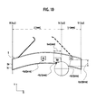
- the driving support system SS3 has a feature in that vehicle information indicative of behavior of the host vehicle A, is obtained for reflection on a display of point information. That is, as shown in FIG. 18, the driving support system SS3 is comprised of, in addition to the display device 1, the vehicle location detector 2, the traffic and road information database 3, the point information acquisition unit 4 and the display control unit 5, a vehicle information acquisition unit 6 that acquires vehicle information indicative of behavior of the host vehicle A, and is configured to supply the display control unit 5 with vehicle information acquired by the vehicle information acquisition unit 6.
- the display control unit 5 is configured to change a display update cycle of the display device 1 depending on vehicle information delivered from the vehicle information acquisition unit 6.
- the driving support system SS3 is similar to the driving support system SS1, set forth above, in respect of basic portions of the configuration and general outline of operations for one cycle and, hence, the driving support system SS3 is described below with a focus on characteristic portions with details of the same configuration and operational content as those of the driving support system SS1 being herein omitted.
- the driving support system SS3 acquires various vehicle information indicative of behavior of the host vehicle A, more particularly, information on a steering speed (rotational speed of a steering wheel), information on a steering angle and information on accelerating operation.
- various on-vehicle electronic equipment are connected via a communication bus line to construct an on-vehicle LAN (Local Area Network) that is supplied with various vehicle information to allow vehicle information to be utilized as needed.
- the on-vehicle LAN is constructed on the host vehicle A and electronic equipment, having a function as the display control unit 5, is connected as one node of this on-vehicle LAN, the on-vehicle LAN can be employed as the vehicle information acquisition unit 6.
- the display control unit 5 With the driving support system SS3, under situations where the display control unit 5 obtains behavior of the host vehicle A based on vehicle information, delivered from the vehicle information acquisition unit 6, and behavior of the host vehicle A drastically varies, the display control unit 5 changes the display update cycle of the display device 1 so as to preclude the updating of the display of point information on the display device 1.
- the direction of the point where the point information related thereto is displayed with respect to the host vehicle A abruptly varies.
- the displays become instable and provide hindrance to the driving operations of the driver in the opposite effect.
- the circumstances wherein behavior of the host vehicle A drastically varies include a status wherein the driver bears a heavy driving load and the display provided on the display device 1 under such a status despoils the driver' s attention to provide hindrance to the driving operations of the driver in the opposite effect.
- the driving support system SS3 is configured to operate such that in cases where discrimination is made based on vehicle information delivered from the vehicle information acquisition unit 6 that behavior of the host vehicle A drastically varies, a control on display of point information set forth above is temporarily interrupted to stop the updating of the display of point information.
- the control of display of point information set forth above repeatedly executed at a given cycle to update the display of point information, to be provided by the display device 5, whereas if the detected steering speed exceeds the given value, the control of display of point information, set forth above, is temporarily interrupted to stop the updating of the display of point information.
- FIG. 19 is a flowchart showing a basic sequence of operations of the driving support system SS3.
- the vehicle information acquisition unit 6 acquires vehicle information to supply to the display control unit 5.
- the display control unit 5 confirms the steering speed among vehicle information and discriminates whether or not the steering speed is less than a given value.
- step S52 if the steering speed is less than the given value, the operations subsequent to step S52 are executed. Also, the operations in steps S53 to S66 in the flowchart of FIG. 19 are identical to those of the operations (the operations in steps S1 to S14 in the flowchart of FIG. 9) of the driving support system SS1 set forth above and, so, detailed description of the same is herein omitted.
- step S52 if the steering speed exceeds the given value, none of the operations subsequent to step S52 are executed and the operations for current cycle are to be ended.
- the display condition for point information determined upon the operations in a preceding cycle, is sustained during a period until discrimination is made in the operations in subsequent cycle that the steering speed is less than the given value, while interrupting the updating of the display of point information.
- the driving support system SS3 is configured to operate such that in cases where discrimination is made based on vehicle information that behavior of the host vehicle A is drastically varies with the steering speed exceeding the given value, the control of display of point information is temporarily interrupted to stop the updating of the display of point information on the display device 1. This effectively prevents adverse affect caused by instable display resulting from drastic variation in behavior of the host vehicle A, and prevents the display of point information from providing hindrance to the driving operations of the driver in the opposite effect.
- an alternative may be other vehicle information such as the steering angle, vehicle speed information and an operating displacement of an accelerator, or another alternative may be a combination of the steering speed and other vehicle information.
- an alternative may be configured such that the driving load of the driver is discriminated based on vehicle information, upon which if the driving load of the driver is discriminated to be great, the updating of the display of point information is interrupted. That is, when the display of point information on the screen Sc of the display device 1 abruptly varies under a situation where the driving load of the driver is great, it is possible that the display catches the driver's eyes to provide hindrance to the driving operations.
- interrupting the updating of the display of point information makes it possible to avoid such an adverse affect in advance, when discrimination is made that the driver's driving load is heavy.
- a method may be applied in which a steering entropy value, indicative of an instable condition of driving operation based on a steering displacement value (steering speed and steering angle), is calculated, and when the steering entropy value is high, discrimination is made that the driving load is high. Also, Detailed techniques for calculating the steering entropy value based on the steering displacement value are disclosed in Japanese Patent Application Laid-open Publications No. 2001-301639, No. 2002-255040 and No. 2003-246227.
- the driving support system SS4 has a fundamental configuration and general outline of operations that are similar to those of the driving support system SS1 set forth above, and differs from the driving support system SS1 in operations when determining display positions of various point information in cases where there are a plurality of point information to be displayed. That is, with the driving support system SS1, in cases where there are plural point information to be displayed, discrimination is made whether or not an overlap occurs in image between these plural point information, if these point information are simultaneously displayed, upon which if discrimination is made that the image overlap occurs, then, either one of point information is selected for display.
- the driving support system SS4 is configured to operate such that display positions of point information related to the points except for a point with a distance shortest from the current location of the host vehicle A among a plurality of points are determined based on a relative positional relationship relative to the point whose distance from the current location of the host vehicle A is shorter than that of the relevant point.
- the driving support system SS4 is described below with a focus on characteristic portions and detailed descriptions of the same configuration and operational content as those of the driving support system SS1 are herein omitted.
- FIG. 20 is a flowchart showing flows of basic sequence of operations to be executed by the driving support system SS4.
- the operation in step S71 and the operation in step S72 are identical to those (the operations in step S1 and step S2 in the flowchart of FIG. 9) executed in the driving support system SS1 set forth above.
- the display control unit 5 discriminates whether or not there are plural point information acquired from the point information acquisition unit 4 to be displayed. If the display points are found to be plural, the display control unit 5 executes the operation in step S74 to calculate the relative positional relationship between adjacent points.
- the display control unit 5 discriminates location of the relevant point with respect to a velocity vector of the host vehicle A when passing a point preceding the relevant point, that is, whether the relevant point is located on a right side or a left side with respect to the velocity vector of the host vehicle A when passing the point preceding the relevant point.
- the display control unit 5 calculates the relative positional relationship between the points P1 and P2 in a manner described below.
- the operation is first executed to acquire a quadratic curve function KP1 with the point P1 at the top thereof using the point P1 located on a side near the current location of the host vehicle A, and associated interpolation points (data contained in road shape information) next to the point P1, after which a tangential line SP1, passing through the point P1 of the curve function KP1.
- the coordinates of the point P2, where the point information related thereto is to be displayed in a stage subsequent to the point P1 is converted to a coordinate system with SP1 plotted on a y-axis and an origin at P1, upon which the operation is executed to discriminate whether the position of the point P2 lies on the right side or the left side with respect to the velocity vector of the host vehicle A passing the point P1. Also, under circumstances where more than three display points are present, the above-described operations are executed for all the points except for the point closest to the host vehicle A, thereby calculating the relative positional relationship for the point on the near side.
- step S73 when discrimination is made in step S73 that there is one point information to be displayed or after the relative positional relationship between the plural points has been calculated in step S74, the display control unit 5 executes the operations subsequent to step S75. Also, in the flowchart shown in FIG. 20, the operations in steps S71 to S79 are identical to those (the operations in steps S3 to S7 in the flowchart of FIG. 9) executed in the driving support system SS1 set forth above.
- the driving support system SS1 is configured such that for all the display points, the operation is executed to calculate display positions Vpn in a lateral direction of the display area on the screen Sc of the display device 1 in step S7
- the driving support system SS4 is configured such that for only point information related to the point closest to the host vehicle A, the display position Vpn in the lateral direction of the display area on the screen Sc of the display device 1 is calculated.
- step S80 the display control unit 5 executes the operation to confirm whether or not point information to be displayed are plural, and depending on the result, determines the display position of point information on the screen Sc of the display device 1.
- the display control unit 5 discriminates in step S81 whether or not the display position Vpn in the lateral direction of the display area, calculated in step S79, falls in the display area Da on the screen Sc of the display device 1. If the display position Vpn falls in the display area Da, in succeeding step S82, the display positions Vpn, Vpcn, calculated in step S79, are determined as the display positions for point information to be provided on the screen Sc of the display device 1 , and the point information are displayed in the display positions Vpn, Vpcn on the screen Sc of the display device in a size Iwn, determined in step S77, in a display color determined in step S78.
- the display control unit 5 executes the operation in step S83 to determine a position in the vicinity of the right side or the left side of the display area Da as the display positions at which the point information is displayed on the screen Sc of the display device lin a size Iwn, determined in step S77, in a display color determined in step S78.
- the display control unit 5 executes the operation in step S84 to discriminate whether or not a display position in the lateral direction of point information of the point closest to the current location of the host vehicle A falls in the display area Da on the screen Sc of the display device 1, that is, whether or not the display position Vpn in the lateral direction of point information, calculated in step S79, falls in the display area Da on the screen Sc of the display device 1.
- the display position on the screen Sc of the display device 1 for point information of the point closest to the current location of the host vehicle A is determined as the display position Vpn, Vpcn, calculated in step S79, and the display positions of the other point information are determined to be positions, which enable for the driver to intuitively and quickly recognize the positional relationship relative to the immediately preceding point, based on the relative positional relationship between the points calculated in step S74, upon which these point information are displayed in a size Iwn, determined in step S77, in a display color determined in step S78.
- point information to be displayed include point information related to the point P1, point information related to the point P2 and point information related to the point P3, respectively, the point P2 lies on the left side with respect to the velocity vector of the host vehicle A passing the point P1 closest to the current location G of the host vehicle, and the point P3 lies on the right side with respect to the velocity vector of the host vehicle A passing the point P2.
- the display control unit 5 allows point information related to the point P1, to be displayed in the display position calculated in step S79, while having point information related to the point P2, displayed in an area on a left side of the point information related to the point P1 and permitting point information related to the point P3, displayed in an area on a right side of the point information related to the point P2.
- the display control unit 5 executes the operation in step S86 to determine a display position on the screen Sc of the display device 1 for point information closest to the current location of the host vehicle A to be a position in the vicinity of the right side or in the vicinity of the left side of the display area Da, while having the display position for the other point information be at a position, which enables the driver to intuitively and quickly recognize the positional relationship relative to the immediately preceding point, based on the relative positional relationship between the points calculated in step S74, upon which these point information are displayed in a size Iwn, determined in step S77, in a display color determined in step S78.
- the display control unit 5 allows point information related to the point P1, to be displayed in an area close proximity to a right side of the display area Da on the screen Sc of the display device 1 and point information related to the point P2, to be displayed in an area adjacent to a left side of point information related to the point P1.
- the series of operation set forth above are repeatedly executed for a given cycle.
- point information related to the respective points P1, P2, P3 are displayed in the display area Da on the screen Sc of the display device 1 such that point information related to the point P2, lies on the left side adj acent to point information related to the point P1, and point information related to the point P3, lie on the right side adjacent to point information related to the point P2.
- point information related to the points P2, P3, are displayed in the display area Da in the screen Sc of the display device 1, respectively, such that point information related to the point P3, lies on the right side adj acent to point information related to the point P2, and during a period wherein the host vehicle A is running on the position at the point G2, point information related to the point P3 is displayed in the screen Sc of the display device 1 at a display position associated with a direction in which the point P3 from the current location of the host vehicle A is present.
- the driving support system SS4 is configured such that in cases where there are plural point information to be displayed, the operation is executed to determine the display positions of point information related to the points other than the point closest in distance to the current location of the host vehicle, based on the relative positional relationship relative to the points on the side nearer to the current location of the host vehicle than the relevant point. Therefore, the respective point information can be displayed in a manner to enable the driver to intuitively and quickly recognize the direction in which the point actually appears after the host vehicle A passes the point immediately preceding the relevant point, thereby making it possible to appropriately supporting the driving operation of the driver.
Abstract
Description
Claims (19)
- A driving support system comprising:a vehicle location detector (2) which detects current location (G) and velocity vector (Gv) of a vehicle (A);a traffic and road information database (3) which stores at least point information related to points (P1, P2, P3) on a route of the vehicle (A);a point information acquisition unit (4) which acquires, from the traffic and road information database (3), the point information of the points (P1, P2, P3) on the route of the vehicle (A), which are located in a given distance (LR) from the current location (G) of the vehicle (A) and to which the vehicle (A) is approaching, based on the current location (G) and velocity vector (Gv) of the vehicle (A) detected by the vehicle location detector (2);a display device (1) having a horizontally long screen (Sc) in a lower area of a windshield of the vehicle (A), which provides on the screen (Sc) thereof displays of the point information acquired by the point information acquisition unit (4) ; anda display control unit (5) for controlling the display device (1), wherein the display control unit (5) determines display positions (Vp1, Vp2, Vp3, Vpc1, Vpc2, Vpc3) on the screen (Sc) of the display device (1) to display the point information, based on a positional relationship between the current location (G) of the vehicle (A) and the points (P1, P2, P3) where the point information related thereto are displayed.
- The driving support system according to claim 1, wherein each of the display positions (Vp1, Vp2, Vp3, Vpc1, Vpc2, Vpc3) is determined to be a position on the screen (Sc) in the direction (V1, V2, V3) of an actual location of the point(P1, P2, P3) where the point information related thereto is displayed, from a driver's eye position (Pd) in the vehicle (A).
- The driving support system according to claim 2, wherein
the display control unit (5) is operative such that in cases where the direction (V1, V2, V3) of the actual location of the point (P1, P2, P3) where the point information related thereto is displayed is deviated from a range of a display area (Da) of the screen (Sc) of the display device (1), the point information related thereto is displayed in a right end or a left end of the display area (Da), while providing a display of information indicative of the deviation. - The driving support system according to any one of claims 1 to 3, wherein
the display control unit (5) determines the display positions (Vpc1, Vpc2, Vpc3) in a vertical direction of a display area (Da) of the screen (Sc) of the display device (1), based on distances (L1, L2, L3) from the current location (G) of the vehicle (A) to the points (P1, P2, P3) where the point information related thereto are displayed. - The driving support system according to any one of claims 1 to 4, wherein
the display control unit (5) determines image sizes (Iwn) of the point information to be displayed, based on distances (L1, L2, L3) from the current location (G) of the vehicle (A) to the points (P1, P2, P3) where the point information related thereto are displayed. - The driving support system according to any one of claims 1 to 5, wherein
the display control unit (5) determines display colors of the point information to be displayed, depending on a priority (Ip) of the point information. - The driving support system according to claim 6, wherein
the display control unit (5) calculates required decelerations (α) at the points (P1, P2, P3) where the point information related thereto are displayed, and determines the priority (Ip) of the point information depending on the calculated required decelerations (α). - The driving support system according to any one of claims 1 to 7, wherein
the point information includes information on advisory speeds when the vehicle (A) passes the relevant points (P1, P2, P3). - The driving support system according to any one of claims 1 to 8, wherein
the display control unit (5) is operative such that in cases where the point information related to a plurality of the points (P1, P2, P3) are acquired by the point information acquisition unit (4), the point information related to the plural points (P1, P2, P3) are simultaneously displayed on the screen (Sc) of the display device (1). - The driving support system according to claim 9, wherein
the display control unit (5) is operative such that in cases where discrimination is made that images of the point information of the plural points (P1, P2, P3) overlap on the screen (Sc) of the display device (1), the point information related to the point closest to the current location (G) of the vehicle (A) is selected for display. - The driving support system according to claim 9, wherein
the display control unit (5) is operative such that in cases where discrimination is made that images of the point information of the plural points (P1, P2, P3) overlap on the screen (Sc) of the display device (1), the point information related to the point whose priority (Ip) is the highest is selected for display. - The driving support system according to claim 9, wherein
the display control unit (5) is operative such that in cases where discrimination is made that images of the point information of the plural points (P1, P2, P3) overlap on the screen (Sc) of the display device (1), the point information are displayed in a manner that the point information to be displayed on the uppermost layer is alternately switched. - The driving support system according to claim 12, wherein
the display control unit (5) determines a display time interval, for which the point information are displayed on the uppermost layer, based on distances (L1, L2, L3) from the current location (G) of the vehicle (A) to the respective points (P1, P2, P3). - The driving support system according to claim 12, wherein
the display control unit (5) determines a display time interval, for which the point information are displayed on the uppermost layer, based on priority (Ip1, Ip2, Ip3) of the point information related to the respective points (P1, P2, P3). - The driving support system according to claim 9, wherein
the display control unit (5) is operative such that the display positions (Vp1, Vp2, Vp3, Vpc1, Vpc2, Vpc3) of the point information related to the points (P1, P2, P3) except for the point in the shortest distance from the current location (G) of the vehicle (A) are determined based on a relative positional relationship with one of the points which is in a shorter distance from the current location (G) of the vehicle (A). - The driving support system according to any one of claims 1 to 15, further comprising:wherein the display control unit (5) changes an updating cycle of the display of the display device (1) based on the vehicle information acquired by the vehicle information acquisition unit (6).a vehicle information acquisition unit (6) acquiring vehicle information indicative of behavior of the vehicle (A),
- The driving support system according to claim 16, wherein
the vehicle information acquisition unit (6) acquires a steering speed of the vehicle (A),
wherein the display control unit (5) updates the display of the display device (1) during a period in which the steering speed is less than a given value, and interrupts the updating of the display of the display device (1) when the steering speed exceeds the given value. - A driving support system comprising:wherein the display control unit (5) determines display positions (Vp1, Vp2, Vp3, Vpc1, Vpc2, Vpc3) on the screen (Sc) of the display device (1) to display the point information, based on a positional relationship between the current location (G) of the vehicle (A) and the points (P1, P2, P3) where the point information related thereto are displayed, while determining image sizes (Iwn) of the point information to be displayed, based on distances (L1, L2, L3) from the current location (G) of the vehicle (A) to the points (P1, P2, P3) where the point information related thereto are displayed.a vehicle location detector (2) which detects current location (G) and velocity vector (Gv) of a vehicle (A);a traffic and road information database (3) which stores at least point information related to points (P1, P2, P3) on a route of the vehicle (A);a point information acquisition unit (4) which acquires, from the traffic and road information database (3), the point information of the points (P1, P2, P3) on the route of the vehicle (A), which are located in a given distance (LR) from the current location (G) of the vehicle (A) and to which the vehicle (A) is approaching, based on the current location (G) and velocity vector (Gv) of the vehicle (A) detected by the vehicle location detector (2);a display device (1) having a horizontally long screen (Sc) in a lower area of a windshield of the vehicle (A), which provides on the screen (Sc) thereof displays of the point information acquired by the point information acquisition unit (4); anda display control unit (5) for controlling the display device (1),
- A driving support method for providing a driver with information related to points (P1, P2 , P3) on a route, comprising:detecting a current location (G) and velocity vector (Gv) of a vehicle (A);acquiring point information related to points (P1, P2, P3) on a route of the vehicle (A), which are located in a given distance (LR) from a current location (G) of the vehicle (A) and to which the vehicle (A) is approaching, based on the detected current location (G) and velocity vector (Gv) of the vehicle (A); anddisplaying the acquired point information on a horizontally long screen (Sc) of a display device (1), disposed in a lower area of a windshield of the vehicle (A), wherein display positions (Vp1, Vp2, Vp3, Vpc1, Vpc2, Vpc3) of the point information on the screen (Sc) of the display device (1) are determined based on a positional relation ship between the current location (G) of the vehicle (A) and the points (P1, P2, P3) where the point information related thereto are displayed, while image sizes (Iwn) of the point information to be displayed are determined based on distances (L1, L2, L3) from the current location (G) of the vehicle (A) to the points (P1, P2, P3) where the point information related thereto are displayed.
Applications Claiming Priority (4)
| Application Number | Priority Date | Filing Date | Title |
|---|---|---|---|
| JP2004173937 | 2004-06-11 | ||
| JP2004173937 | 2004-06-11 | ||
| JP2005113418A JP4639921B2 (en) | 2004-06-11 | 2005-04-11 | Driving assistance device |
| JP2005113418 | 2005-04-11 |
Publications (2)
| Publication Number | Publication Date |
|---|---|
| EP1605233A1 true EP1605233A1 (en) | 2005-12-14 |
| EP1605233B1 EP1605233B1 (en) | 2015-02-25 |
Family
ID=34979413
Family Applications (1)
| Application Number | Title | Priority Date | Filing Date |
|---|---|---|---|
| EP05012247.2A Expired - Fee Related EP1605233B1 (en) | 2004-06-11 | 2005-06-07 | Driving support system and driving support method |
Country Status (3)
| Country | Link |
|---|---|
| US (1) | US7496446B2 (en) |
| EP (1) | EP1605233B1 (en) |
| JP (1) | JP4639921B2 (en) |
Cited By (4)
| Publication number | Priority date | Publication date | Assignee | Title |
|---|---|---|---|---|
| WO2008041899A1 (en) * | 2006-10-03 | 2008-04-10 | Autoliv Development Ab | A vehicle safety system |
| WO2011061384A3 (en) * | 2009-11-23 | 2011-07-14 | Valtion Teknillinen Tutkimuskeskus | Method and device for guiding the driver of a vehicle |
| WO2018145954A1 (en) * | 2017-02-13 | 2018-08-16 | Jaguar Land Rover Limited | Controlling the operation of a head-up display apparatus |
| CN111417885A (en) * | 2017-11-07 | 2020-07-14 | 大众汽车有限公司 | System and method for determining a pose of augmented reality glasses, system and method for calibrating augmented reality glasses, method for supporting pose determination of augmented reality glasses, and motor vehicle suitable for the method |
Families Citing this family (26)
| Publication number | Priority date | Publication date | Assignee | Title |
|---|---|---|---|---|
| DE102004055835A1 (en) * | 2004-07-09 | 2006-02-02 | Volkswagen Ag | Display device for a vehicle and method for displaying information |
| JP4682732B2 (en) * | 2005-07-27 | 2011-05-11 | 株式会社デンソー | Navigation device |
| JP4432929B2 (en) * | 2006-04-25 | 2010-03-17 | トヨタ自動車株式会社 | Parking assistance device and parking assistance method |
| KR100779024B1 (en) * | 2006-04-27 | 2007-11-23 | 팅크웨어(주) | Method and system for displaying traveling-position of move object |
| DE102006039376A1 (en) * | 2006-08-22 | 2008-03-06 | Bayerische Motoren Werke Ag | Vehicle, has detection device that detects driving situation information, and control device that is arranged such that ahead lying road section is displayed on display device depending on detected information |
| WO2008139516A1 (en) * | 2007-04-27 | 2008-11-20 | Aisin Aw Co., Ltd. | Driving support system |
| JP4513826B2 (en) * | 2007-05-24 | 2010-07-28 | 株式会社デンソー | Route display device and route display system |
| JP5239888B2 (en) * | 2009-01-21 | 2013-07-17 | 三菱自動車工業株式会社 | Collision prevention system by exchanging vehicle position information |
| JP5321140B2 (en) * | 2009-03-02 | 2013-10-23 | 日産自動車株式会社 | Gaze guidance device |
| JP5343666B2 (en) * | 2009-03-31 | 2013-11-13 | 日産自動車株式会社 | Information presenting apparatus and information presenting method |
| US8358224B2 (en) * | 2009-04-02 | 2013-01-22 | GM Global Technology Operations LLC | Point of interest location marking on full windshield head-up display |
| JP5278378B2 (en) * | 2009-07-30 | 2013-09-04 | 日産自動車株式会社 | Vehicle driving support device and vehicle driving support method |
| JP5590684B2 (en) * | 2009-12-10 | 2014-09-17 | パナソニック株式会社 | Information display device and information display method |
| KR101786583B1 (en) * | 2011-02-14 | 2017-10-19 | 주식회사 케이티 | Apparatus for providing traffic moving images |
| DE102012005858A1 (en) * | 2012-03-22 | 2013-09-26 | Audi Ag | Method for reproducing information in a motor vehicle |
| JP6178592B2 (en) * | 2013-03-07 | 2017-08-09 | 古野電気株式会社 | Status display device, status display program, and status display method |
| JP5987791B2 (en) | 2013-06-28 | 2016-09-07 | 株式会社デンソー | Head-up display and program |
| JP5983547B2 (en) * | 2013-07-02 | 2016-08-31 | 株式会社デンソー | Head-up display and program |
| DE102013013326B3 (en) * | 2013-08-09 | 2014-12-24 | Audi Ag | Movable representation of information in the motor vehicle |
| KR102200121B1 (en) * | 2014-02-17 | 2021-01-08 | 삼성전자 주식회사 | Apparatus and method forecasting vehicle flow |
| JP6191573B2 (en) * | 2014-09-29 | 2017-09-06 | マツダ株式会社 | Vehicle visibility adjustment device |
| JP6317315B2 (en) * | 2015-12-22 | 2018-04-25 | 本田技研工業株式会社 | Sign information display device and method |
| US10232856B2 (en) * | 2016-07-28 | 2019-03-19 | Ford Global Technologies, Llc | Vehicle user-communication system and method |
| KR20180046036A (en) * | 2016-10-27 | 2018-05-08 | 이해곤 | Car nevigation system of check the location and battery charge of the other ev car |
| JP2019113324A (en) * | 2017-12-21 | 2019-07-11 | アイシン・エィ・ダブリュ株式会社 | Speed guide system and speed guide program |
| JP7009436B2 (en) * | 2019-12-13 | 2022-01-25 | 本田技研工業株式会社 | Vehicle display device and parking support system |
Citations (6)
| Publication number | Priority date | Publication date | Assignee | Title |
|---|---|---|---|---|
| JPH0934352A (en) | 1995-07-24 | 1997-02-07 | Honda Motor Co Ltd | Head-up display device for car navigation |
| JPH09189565A (en) | 1996-01-11 | 1997-07-22 | Yazaki Corp | Navigation device for vehicle |
| EP0833291A1 (en) | 1996-09-30 | 1998-04-01 | Aisin Aw Co., Ltd. | Vehicle navigation apparatus and storage medium |
| EP0869300A1 (en) * | 1996-10-25 | 1998-10-07 | Equos Research Co. Ltd. | Vehicle control device |
| US20020059017A1 (en) * | 2000-10-16 | 2002-05-16 | Kenichiro Yamane | Probe car control method and traffic control system |
| US20030130780A1 (en) * | 2001-12-25 | 2003-07-10 | Aisin Aw Co., Ltd. | Driving force control apparatus for vehicle |
Family Cites Families (9)
| Publication number | Priority date | Publication date | Assignee | Title |
|---|---|---|---|---|
| JPS62245158A (en) * | 1986-04-17 | 1987-10-26 | Nippon Denso Co Ltd | Ground speed detector |
| JPS6454215A (en) * | 1987-08-25 | 1989-03-01 | Japan Aviation Electron | Car navigation system |
| JP3444961B2 (en) * | 1994-05-09 | 2003-09-08 | 株式会社ザナヴィ・インフォマティクス | Vehicle navigation system |
| US6272431B1 (en) * | 1997-04-29 | 2001-08-07 | Thomas Zamojdo | Method for displaying a map in a vehicle en-route guidance system |
| JP2000331289A (en) * | 1999-05-24 | 2000-11-30 | Nissan Motor Co Ltd | Display device for vehicle |
| JP2001301639A (en) | 2000-04-24 | 2001-10-31 | Nissan Motor Co Ltd | Steering device for vehicle |
| JP4449162B2 (en) * | 2000-05-09 | 2010-04-14 | 株式会社エクォス・リサーチ | Map display device |
| JP2002255040A (en) | 2001-02-28 | 2002-09-11 | Nissan Motor Co Ltd | Steering device for vehicle |
| JP2003246227A (en) | 2002-02-25 | 2003-09-02 | Nissan Motor Co Ltd | Driving operation monitoring unit for vehicle |
-
2005
- 2005-04-11 JP JP2005113418A patent/JP4639921B2/en not_active Expired - Fee Related
- 2005-06-07 EP EP05012247.2A patent/EP1605233B1/en not_active Expired - Fee Related
- 2005-06-08 US US11/147,336 patent/US7496446B2/en active Active
Patent Citations (6)
| Publication number | Priority date | Publication date | Assignee | Title |
|---|---|---|---|---|
| JPH0934352A (en) | 1995-07-24 | 1997-02-07 | Honda Motor Co Ltd | Head-up display device for car navigation |
| JPH09189565A (en) | 1996-01-11 | 1997-07-22 | Yazaki Corp | Navigation device for vehicle |
| EP0833291A1 (en) | 1996-09-30 | 1998-04-01 | Aisin Aw Co., Ltd. | Vehicle navigation apparatus and storage medium |
| EP0869300A1 (en) * | 1996-10-25 | 1998-10-07 | Equos Research Co. Ltd. | Vehicle control device |
| US20020059017A1 (en) * | 2000-10-16 | 2002-05-16 | Kenichiro Yamane | Probe car control method and traffic control system |
| US20030130780A1 (en) * | 2001-12-25 | 2003-07-10 | Aisin Aw Co., Ltd. | Driving force control apparatus for vehicle |
Cited By (5)
| Publication number | Priority date | Publication date | Assignee | Title |
|---|---|---|---|---|
| WO2008041899A1 (en) * | 2006-10-03 | 2008-04-10 | Autoliv Development Ab | A vehicle safety system |
| WO2011061384A3 (en) * | 2009-11-23 | 2011-07-14 | Valtion Teknillinen Tutkimuskeskus | Method and device for guiding the driver of a vehicle |
| WO2018145954A1 (en) * | 2017-02-13 | 2018-08-16 | Jaguar Land Rover Limited | Controlling the operation of a head-up display apparatus |
| US11214279B2 (en) | 2017-02-13 | 2022-01-04 | Jaguar Land Rover Limited | Controlling the operation of a head-up display apparatus |
| CN111417885A (en) * | 2017-11-07 | 2020-07-14 | 大众汽车有限公司 | System and method for determining a pose of augmented reality glasses, system and method for calibrating augmented reality glasses, method for supporting pose determination of augmented reality glasses, and motor vehicle suitable for the method |
Also Published As
| Publication number | Publication date |
|---|---|
| US7496446B2 (en) | 2009-02-24 |
| US20050278113A1 (en) | 2005-12-15 |
| EP1605233B1 (en) | 2015-02-25 |
| JP2006023277A (en) | 2006-01-26 |
| JP4639921B2 (en) | 2011-02-23 |
Similar Documents
| Publication | Publication Date | Title |
|---|---|---|
| EP1605233B1 (en) | Driving support system and driving support method | |
| US7522997B2 (en) | Navigation apparatus | |
| JP4646923B2 (en) | Navigation system and portable terminal device | |
| EP1498696A1 (en) | Turn-by-turn navigation system and next direction guidance method using the same | |
| JP4725509B2 (en) | New road width calculation system | |
| JP2008001120A (en) | Display control device for vehicle | |
| JP2011215080A (en) | Route search device and route guidance system | |
| JP6558129B2 (en) | Driving support system, driving support method, and computer program | |
| JP2008197725A (en) | Traffic information generation device, traffic information providing system, and traffic information generation method | |
| US20230135641A1 (en) | Superimposed image display device | |
| US11493357B2 (en) | Superimposed image display device, superimposed image drawing method, and computer program | |
| JP2008064483A (en) | Vehicle-mounted navigation system, method, and program | |
| JP5201189B2 (en) | Driving support device and driving support method | |
| JP2005265573A (en) | Vehicle mounted navigation device, navigation system | |
| JP4723261B2 (en) | Navigation system, navigation device and program | |
| US20210291860A1 (en) | Driving assistance system and driving assistance program | |
| US10564001B2 (en) | Navigation system with route displaying mechanism and method of operation thereof | |
| JP2013122381A (en) | Navigation apparatus | |
| JP2019215254A (en) | Movement guidance device and computer program | |
| JP7464546B2 (en) | Map Display System | |
| WO2022186003A1 (en) | Lane determination device, lane change determination program, and data structure | |
| JP4973184B2 (en) | Multi-view display control apparatus and multi-view display control method | |
| JP2023038558A (en) | Superimposed image display device | |
| CN114375384A (en) | Navigation device, control method for navigation device, and control program for navigation device | |
| JP2023064957A (en) | Superimposed image display device |
Legal Events
| Date | Code | Title | Description |
|---|---|---|---|
| PUAI | Public reference made under article 153(3) epc to a published international application that has entered the european phase |
Free format text: ORIGINAL CODE: 0009012 |
|
| 17P | Request for examination filed |
Effective date: 20050607 |
|
| AK | Designated contracting states |
Kind code of ref document: A1 Designated state(s): AT BE BG CH CY CZ DE DK EE ES FI FR GB GR HU IE IS IT LI LT LU MC NL PL PT RO SE SI SK TR |
|
| AX | Request for extension of the european patent |
Extension state: AL BA HR LV MK YU |
|
| AKX | Designation fees paid |
Designated state(s): DE FR GB |
|
| 17Q | First examination report despatched |
Effective date: 20110816 |
|
| GRAP | Despatch of communication of intention to grant a patent |
Free format text: ORIGINAL CODE: EPIDOSNIGR1 |
|
| INTG | Intention to grant announced |
Effective date: 20141014 |
|
| GRAS | Grant fee paid |
Free format text: ORIGINAL CODE: EPIDOSNIGR3 |
|
| GRAA | (expected) grant |
Free format text: ORIGINAL CODE: 0009210 |
|
| AK | Designated contracting states |
Kind code of ref document: B1 Designated state(s): DE FR GB |
|
| REG | Reference to a national code |
Ref country code: GB Ref legal event code: FG4D |
|
| REG | Reference to a national code |
Ref country code: DE Ref legal event code: R096 Ref document number: 602005045870 Country of ref document: DE Effective date: 20150409 |
|
| REG | Reference to a national code |
Ref country code: DE Ref legal event code: R097 Ref document number: 602005045870 Country of ref document: DE |
|
| PLBE | No opposition filed within time limit |
Free format text: ORIGINAL CODE: 0009261 |
|
| STAA | Information on the status of an ep patent application or granted ep patent |
Free format text: STATUS: NO OPPOSITION FILED WITHIN TIME LIMIT |
|
| 26N | No opposition filed |
Effective date: 20151126 |
|
| REG | Reference to a national code |
Ref country code: FR Ref legal event code: PLFP Year of fee payment: 12 |
|
| REG | Reference to a national code |
Ref country code: FR Ref legal event code: PLFP Year of fee payment: 13 |
|
| REG | Reference to a national code |
Ref country code: FR Ref legal event code: PLFP Year of fee payment: 14 |
|
| PGFP | Annual fee paid to national office [announced via postgrant information from national office to epo] |
Ref country code: DE Payment date: 20200527 Year of fee payment: 16 Ref country code: FR Payment date: 20200512 Year of fee payment: 16 |
|
| PGFP | Annual fee paid to national office [announced via postgrant information from national office to epo] |
Ref country code: GB Payment date: 20200527 Year of fee payment: 16 |
|
| REG | Reference to a national code |
Ref country code: DE Ref legal event code: R119 Ref document number: 602005045870 Country of ref document: DE |
|
| GBPC | Gb: european patent ceased through non-payment of renewal fee |
Effective date: 20210607 |
|
| PG25 | Lapsed in a contracting state [announced via postgrant information from national office to epo] |
Ref country code: GB Free format text: LAPSE BECAUSE OF NON-PAYMENT OF DUE FEES Effective date: 20210607 Ref country code: DE Free format text: LAPSE BECAUSE OF NON-PAYMENT OF DUE FEES Effective date: 20220101 |
|
| PG25 | Lapsed in a contracting state [announced via postgrant information from national office to epo] |
Ref country code: FR Free format text: LAPSE BECAUSE OF NON-PAYMENT OF DUE FEES Effective date: 20210630 |