EP1613244B1 - Medical appliance optical delivery and deployment apparatus and method - Google Patents
Medical appliance optical delivery and deployment apparatus and method Download PDFInfo
- Publication number
- EP1613244B1 EP1613244B1 EP04759040A EP04759040A EP1613244B1 EP 1613244 B1 EP1613244 B1 EP 1613244B1 EP 04759040 A EP04759040 A EP 04759040A EP 04759040 A EP04759040 A EP 04759040A EP 1613244 B1 EP1613244 B1 EP 1613244B1
- Authority
- EP
- European Patent Office
- Prior art keywords
- tubular member
- stent
- inner tubular
- outer tubular
- deployment
- Prior art date
- Legal status (The legal status is an assumption and is not a legal conclusion. Google has not performed a legal analysis and makes no representation as to the accuracy of the status listed.)
- Expired - Lifetime
Links
- 230000003287 optical effect Effects 0.000 title claims description 58
- 238000000034 method Methods 0.000 title claims description 20
- 230000007246 mechanism Effects 0.000 claims abstract description 37
- 230000000295 complement effect Effects 0.000 claims description 8
- 239000003550 marker Substances 0.000 claims description 8
- 239000000463 material Substances 0.000 claims description 6
- 239000013307 optical fiber Substances 0.000 claims description 5
- 229920002725 thermoplastic elastomer Polymers 0.000 claims description 3
- 238000002604 ultrasonography Methods 0.000 claims description 2
- 230000001419 dependent effect Effects 0.000 claims 3
- 238000012800 visualization Methods 0.000 description 20
- 239000002246 antineoplastic agent Substances 0.000 description 10
- 239000003795 chemical substances by application Substances 0.000 description 10
- 229940127089 cytotoxic agent Drugs 0.000 description 9
- 208000002352 blister Diseases 0.000 description 7
- 238000013461 design Methods 0.000 description 7
- 206010028980 Neoplasm Diseases 0.000 description 6
- 208000031481 Pathologic Constriction Diseases 0.000 description 6
- 230000000975 bioactive effect Effects 0.000 description 6
- 238000003780 insertion Methods 0.000 description 6
- 230000037431 insertion Effects 0.000 description 6
- 229940100198 alkylating agent Drugs 0.000 description 5
- 239000002168 alkylating agent Substances 0.000 description 5
- 230000006870 function Effects 0.000 description 5
- 230000000670 limiting effect Effects 0.000 description 5
- 230000001225 therapeutic effect Effects 0.000 description 5
- AOJJSUZBOXZQNB-TZSSRYMLSA-N Doxorubicin Chemical compound O([C@H]1C[C@@](O)(CC=2C(O)=C3C(=O)C=4C=CC=C(C=4C(=O)C3=C(O)C=21)OC)C(=O)CO)[C@H]1C[C@H](N)[C@H](O)[C@H](C)O1 AOJJSUZBOXZQNB-TZSSRYMLSA-N 0.000 description 4
- RJURFGZVJUQBHK-UHFFFAOYSA-N actinomycin D Natural products CC1OC(=O)C(C(C)C)N(C)C(=O)CN(C)C(=O)C2CCCN2C(=O)C(C(C)C)NC(=O)C1NC(=O)C1=C(N)C(=O)C(C)=C2OC(C(C)=CC=C3C(=O)NC4C(=O)NC(C(N5CCCC5C(=O)N(C)CC(=O)N(C)C(C(C)C)C(=O)OC4C)=O)C(C)C)=C3N=C21 RJURFGZVJUQBHK-UHFFFAOYSA-N 0.000 description 4
- 210000003484 anatomy Anatomy 0.000 description 4
- 230000008901 benefit Effects 0.000 description 4
- RWSXRVCMGQZWBV-WDSKDSINSA-N glutathione Chemical compound OC(=O)[C@@H](N)CCC(=O)N[C@@H](CS)C(=O)NCC(O)=O RWSXRVCMGQZWBV-WDSKDSINSA-N 0.000 description 4
- JYGXADMDTFJGBT-VWUMJDOOSA-N hydrocortisone Chemical compound O=C1CC[C@]2(C)[C@H]3[C@@H](O)C[C@](C)([C@@](CC4)(O)C(=O)CO)[C@@H]4[C@@H]3CCC2=C1 JYGXADMDTFJGBT-VWUMJDOOSA-N 0.000 description 4
- 235000018102 proteins Nutrition 0.000 description 4
- 102000004169 proteins and genes Human genes 0.000 description 4
- 108090000623 proteins and genes Proteins 0.000 description 4
- 230000002685 pulmonary effect Effects 0.000 description 4
- 230000036262 stenosis Effects 0.000 description 4
- 208000037804 stenosis Diseases 0.000 description 4
- 210000001519 tissue Anatomy 0.000 description 4
- 238000011282 treatment Methods 0.000 description 4
- VSNHCAURESNICA-UHFFFAOYSA-N Hydroxyurea Chemical compound NC(=O)NO VSNHCAURESNICA-UHFFFAOYSA-N 0.000 description 3
- 239000000317 Topoisomerase II Inhibitor Substances 0.000 description 3
- 102000004243 Tubulin Human genes 0.000 description 3
- 108090000704 Tubulin Proteins 0.000 description 3
- -1 amino, carboxyl Chemical group 0.000 description 3
- 230000000340 anti-metabolite Effects 0.000 description 3
- 229940100197 antimetabolite Drugs 0.000 description 3
- 239000002256 antimetabolite Substances 0.000 description 3
- 230000000973 chemotherapeutic effect Effects 0.000 description 3
- 150000001875 compounds Chemical class 0.000 description 3
- 230000007547 defect Effects 0.000 description 3
- 229960001330 hydroxycarbamide Drugs 0.000 description 3
- 230000002452 interceptive effect Effects 0.000 description 3
- 238000004519 manufacturing process Methods 0.000 description 3
- 229910052751 metal Inorganic materials 0.000 description 3
- 239000002184 metal Substances 0.000 description 3
- 239000000126 substance Substances 0.000 description 3
- 229920002994 synthetic fiber Polymers 0.000 description 3
- 238000000015 thermotherapy Methods 0.000 description 3
- 230000000007 visual effect Effects 0.000 description 3
- 102000015790 Asparaginase Human genes 0.000 description 2
- 108010024976 Asparaginase Proteins 0.000 description 2
- IJGRMHOSHXDMSA-UHFFFAOYSA-N Atomic nitrogen Chemical compound N#N IJGRMHOSHXDMSA-UHFFFAOYSA-N 0.000 description 2
- 108010006654 Bleomycin Proteins 0.000 description 2
- CMSMOCZEIVJLDB-UHFFFAOYSA-N Cyclophosphamide Chemical compound ClCCN(CCCl)P1(=O)NCCCO1 CMSMOCZEIVJLDB-UHFFFAOYSA-N 0.000 description 2
- 108020004414 DNA Proteins 0.000 description 2
- 239000012626 DNA minor groove binder Substances 0.000 description 2
- 230000006820 DNA synthesis Effects 0.000 description 2
- 229940124087 DNA topoisomerase II inhibitor Drugs 0.000 description 2
- 108010092160 Dactinomycin Proteins 0.000 description 2
- 108010024636 Glutathione Proteins 0.000 description 2
- 102000029749 Microtubule Human genes 0.000 description 2
- 108091022875 Microtubule Proteins 0.000 description 2
- MUMGGOZAMZWBJJ-DYKIIFRCSA-N Testostosterone Chemical compound O=C1CC[C@]2(C)[C@H]3CC[C@](C)([C@H](CC4)O)[C@@H]4[C@@H]3CCC2=C1 MUMGGOZAMZWBJJ-DYKIIFRCSA-N 0.000 description 2
- RJURFGZVJUQBHK-IIXSONLDSA-N actinomycin D Chemical compound C[C@H]1OC(=O)[C@H](C(C)C)N(C)C(=O)CN(C)C(=O)[C@@H]2CCCN2C(=O)[C@@H](C(C)C)NC(=O)[C@H]1NC(=O)C1=C(N)C(=O)C(C)=C2OC(C(C)=CC=C3C(=O)N[C@@H]4C(=O)N[C@@H](C(N5CCC[C@H]5C(=O)N(C)CC(=O)N(C)[C@@H](C(C)C)C(=O)O[C@@H]4C)=O)C(C)C)=C3N=C21 RJURFGZVJUQBHK-IIXSONLDSA-N 0.000 description 2
- 230000001919 adrenal effect Effects 0.000 description 2
- 229960000473 altretamine Drugs 0.000 description 2
- 235000001014 amino acid Nutrition 0.000 description 2
- 229940024606 amino acid Drugs 0.000 description 2
- 150000001413 amino acids Chemical class 0.000 description 2
- 229960003272 asparaginase Drugs 0.000 description 2
- DCXYFEDJOCDNAF-UHFFFAOYSA-M asparaginate Chemical compound [O-]C(=O)C(N)CC(N)=O DCXYFEDJOCDNAF-UHFFFAOYSA-M 0.000 description 2
- 230000009286 beneficial effect Effects 0.000 description 2
- 229960001561 bleomycin Drugs 0.000 description 2
- OYVAGSVQBOHSSS-UAPAGMARSA-O bleomycin A2 Chemical compound N([C@H](C(=O)N[C@H](C)[C@@H](O)[C@H](C)C(=O)N[C@@H]([C@H](O)C)C(=O)NCCC=1SC=C(N=1)C=1SC=C(N=1)C(=O)NCCC[S+](C)C)[C@@H](O[C@H]1[C@H]([C@@H](O)[C@H](O)[C@H](CO)O1)O[C@@H]1[C@H]([C@@H](OC(N)=O)[C@H](O)[C@@H](CO)O1)O)C=1N=CNC=1)C(=O)C1=NC([C@H](CC(N)=O)NC[C@H](N)C(N)=O)=NC(N)=C1C OYVAGSVQBOHSSS-UAPAGMARSA-O 0.000 description 2
- 201000011510 cancer Diseases 0.000 description 2
- 210000004027 cell Anatomy 0.000 description 2
- 230000001413 cellular effect Effects 0.000 description 2
- 238000002512 chemotherapy Methods 0.000 description 2
- DQLATGHUWYMOKM-UHFFFAOYSA-L cisplatin Chemical compound N[Pt](N)(Cl)Cl DQLATGHUWYMOKM-UHFFFAOYSA-L 0.000 description 2
- 229960004316 cisplatin Drugs 0.000 description 2
- 238000010168 coupling process Methods 0.000 description 2
- 238000000315 cryotherapy Methods 0.000 description 2
- 229960004397 cyclophosphamide Drugs 0.000 description 2
- 229960000640 dactinomycin Drugs 0.000 description 2
- 230000002950 deficient Effects 0.000 description 2
- 229960004679 doxorubicin Drugs 0.000 description 2
- 238000001647 drug administration Methods 0.000 description 2
- VJJPUSNTGOMMGY-MRVIYFEKSA-N etoposide Chemical compound COC1=C(O)C(OC)=CC([C@@H]2C3=CC=4OCOC=4C=C3[C@@H](O[C@H]3[C@@H]([C@@H](O)[C@@H]4O[C@H](C)OC[C@H]4O3)O)[C@@H]3[C@@H]2C(OC3)=O)=C1 VJJPUSNTGOMMGY-MRVIYFEKSA-N 0.000 description 2
- 229960005420 etoposide Drugs 0.000 description 2
- ODKNJVUHOIMIIZ-RRKCRQDMSA-N floxuridine Chemical compound C1[C@H](O)[C@@H](CO)O[C@H]1N1C(=O)NC(=O)C(F)=C1 ODKNJVUHOIMIIZ-RRKCRQDMSA-N 0.000 description 2
- 229960000390 fludarabine Drugs 0.000 description 2
- GIUYCYHIANZCFB-FJFJXFQQSA-N fludarabine phosphate Chemical compound C1=NC=2C(N)=NC(F)=NC=2N1[C@@H]1O[C@H](COP(O)(O)=O)[C@@H](O)[C@@H]1O GIUYCYHIANZCFB-FJFJXFQQSA-N 0.000 description 2
- 229960003180 glutathione Drugs 0.000 description 2
- UUVWYPNAQBNQJQ-UHFFFAOYSA-N hexamethylmelamine Chemical compound CN(C)C1=NC(N(C)C)=NC(N(C)C)=N1 UUVWYPNAQBNQJQ-UHFFFAOYSA-N 0.000 description 2
- 229940125697 hormonal agent Drugs 0.000 description 2
- 229960000890 hydrocortisone Drugs 0.000 description 2
- 210000004688 microtubule Anatomy 0.000 description 2
- CFCUWKMKBJTWLW-BKHRDMLASA-N mithramycin Chemical compound O([C@@H]1C[C@@H](O[C@H](C)[C@H]1O)OC=1C=C2C=C3C[C@H]([C@@H](C(=O)C3=C(O)C2=C(O)C=1C)O[C@@H]1O[C@H](C)[C@@H](O)[C@H](O[C@@H]2O[C@H](C)[C@H](O)[C@H](O[C@@H]3O[C@H](C)[C@@H](O)[C@@](C)(O)C3)C2)C1)[C@H](OC)C(=O)[C@@H](O)[C@@H](C)O)[C@H]1C[C@@H](O)[C@H](O)[C@@H](C)O1 CFCUWKMKBJTWLW-BKHRDMLASA-N 0.000 description 2
- 108020004707 nucleic acids Proteins 0.000 description 2
- 102000039446 nucleic acids Human genes 0.000 description 2
- 150000007523 nucleic acids Chemical class 0.000 description 2
- 238000002428 photodynamic therapy Methods 0.000 description 2
- HWLDNSXPUQTBOD-UHFFFAOYSA-N platinum-iridium alloy Chemical compound [Ir].[Pt] HWLDNSXPUQTBOD-UHFFFAOYSA-N 0.000 description 2
- 229960003171 plicamycin Drugs 0.000 description 2
- 229920002635 polyurethane Polymers 0.000 description 2
- 239000004814 polyurethane Substances 0.000 description 2
- 230000000241 respiratory effect Effects 0.000 description 2
- 230000000717 retained effect Effects 0.000 description 2
- 238000007789 sealing Methods 0.000 description 2
- 230000002269 spontaneous effect Effects 0.000 description 2
- RCINICONZNJXQF-MZXODVADSA-N taxol Chemical compound O([C@@H]1[C@@]2(C[C@@H](C(C)=C(C2(C)C)[C@H](C([C@]2(C)[C@@H](O)C[C@H]3OC[C@]3([C@H]21)OC(C)=O)=O)OC(=O)C)OC(=O)[C@H](O)[C@@H](NC(=O)C=1C=CC=CC=1)C=1C=CC=CC=1)O)C(=O)C1=CC=CC=C1 RCINICONZNJXQF-MZXODVADSA-N 0.000 description 2
- NRUKOCRGYNPUPR-QBPJDGROSA-N teniposide Chemical compound COC1=C(O)C(OC)=CC([C@@H]2C3=CC=4OCOC=4C=C3[C@@H](O[C@H]3[C@@H]([C@@H](O)[C@@H]4O[C@@H](OC[C@H]4O3)C=3SC=CC=3)O)[C@@H]3[C@@H]2C(OC3)=O)=C1 NRUKOCRGYNPUPR-QBPJDGROSA-N 0.000 description 2
- 229960001278 teniposide Drugs 0.000 description 2
- WYWHKKSPHMUBEB-UHFFFAOYSA-N tioguanine Chemical compound N1C(N)=NC(=S)C2=C1N=CN2 WYWHKKSPHMUBEB-UHFFFAOYSA-N 0.000 description 2
- FPVKHBSQESCIEP-UHFFFAOYSA-N (8S)-3-(2-deoxy-beta-D-erythro-pentofuranosyl)-3,6,7,8-tetrahydroimidazo[4,5-d][1,3]diazepin-8-ol Natural products C1C(O)C(CO)OC1N1C(NC=NCC2O)=C2N=C1 FPVKHBSQESCIEP-UHFFFAOYSA-N 0.000 description 1
- FDKXTQMXEQVLRF-ZHACJKMWSA-N (E)-dacarbazine Chemical compound CN(C)\N=N\c1[nH]cnc1C(N)=O FDKXTQMXEQVLRF-ZHACJKMWSA-N 0.000 description 1
- 108091032973 (ribonucleotides)n+m Proteins 0.000 description 1
- BFPYWIDHMRZLRN-UHFFFAOYSA-N 17alpha-ethynyl estradiol Natural products OC1=CC=C2C3CCC(C)(C(CC4)(O)C#C)C4C3CCC2=C1 BFPYWIDHMRZLRN-UHFFFAOYSA-N 0.000 description 1
- GCKMFJBGXUYNAG-UHFFFAOYSA-N 17alpha-methyltestosterone Natural products C1CC2=CC(=O)CCC2(C)C2C1C1CCC(C)(O)C1(C)CC2 GCKMFJBGXUYNAG-UHFFFAOYSA-N 0.000 description 1
- IDPUKCWIGUEADI-UHFFFAOYSA-N 5-[bis(2-chloroethyl)amino]uracil Chemical compound ClCCN(CCCl)C1=CNC(=O)NC1=O IDPUKCWIGUEADI-UHFFFAOYSA-N 0.000 description 1
- NMUSYJAQQFHJEW-KVTDHHQDSA-N 5-azacytidine Chemical compound O=C1N=C(N)N=CN1[C@H]1[C@H](O)[C@H](O)[C@@H](CO)O1 NMUSYJAQQFHJEW-KVTDHHQDSA-N 0.000 description 1
- VHRSUDSXCMQTMA-PJHHCJLFSA-N 6alpha-methylprednisolone Chemical compound C([C@@]12C)=CC(=O)C=C1[C@@H](C)C[C@@H]1[C@@H]2[C@@H](O)C[C@]2(C)[C@@](O)(C(=O)CO)CC[C@H]21 VHRSUDSXCMQTMA-PJHHCJLFSA-N 0.000 description 1
- STQGQHZAVUOBTE-UHFFFAOYSA-N 7-Cyan-hept-2t-en-4,6-diinsaeure Natural products C1=2C(O)=C3C(=O)C=4C(OC)=CC=CC=4C(=O)C3=C(O)C=2CC(O)(C(C)=O)CC1OC1CC(N)C(O)C(C)O1 STQGQHZAVUOBTE-UHFFFAOYSA-N 0.000 description 1
- DCXYFEDJOCDNAF-UHFFFAOYSA-N Asparagine Natural products OC(=O)C(N)CC(N)=O DCXYFEDJOCDNAF-UHFFFAOYSA-N 0.000 description 1
- COVZYZSDYWQREU-UHFFFAOYSA-N Busulfan Chemical compound CS(=O)(=O)OCCCCOS(C)(=O)=O COVZYZSDYWQREU-UHFFFAOYSA-N 0.000 description 1
- LTKHPMDRMUCUEB-IBGZPJMESA-N CB3717 Chemical compound C=1C=C2NC(N)=NC(=O)C2=CC=1CN(CC#C)C1=CC=C(C(=O)N[C@@H](CCC(O)=O)C(O)=O)C=C1 LTKHPMDRMUCUEB-IBGZPJMESA-N 0.000 description 1
- 190000008236 Carboplatin Chemical compound 0.000 description 1
- JWBOIMRXGHLCPP-UHFFFAOYSA-N Chloditan Chemical compound C=1C=CC=C(Cl)C=1C(C(Cl)Cl)C1=CC=C(Cl)C=C1 JWBOIMRXGHLCPP-UHFFFAOYSA-N 0.000 description 1
- UHDGCWIWMRVCDJ-CCXZUQQUSA-N Cytarabine Chemical compound O=C1N=C(N)C=CN1[C@H]1[C@@H](O)[C@H](O)[C@@H](CO)O1 UHDGCWIWMRVCDJ-CCXZUQQUSA-N 0.000 description 1
- 230000004543 DNA replication Effects 0.000 description 1
- 102000004190 Enzymes Human genes 0.000 description 1
- 108090000790 Enzymes Proteins 0.000 description 1
- BFPYWIDHMRZLRN-SLHNCBLASA-N Ethinyl estradiol Chemical compound OC1=CC=C2[C@H]3CC[C@](C)([C@](CC4)(O)C#C)[C@@H]4[C@@H]3CCC2=C1 BFPYWIDHMRZLRN-SLHNCBLASA-N 0.000 description 1
- GHASVSINZRGABV-UHFFFAOYSA-N Fluorouracil Chemical compound FC1=CNC(=O)NC1=O GHASVSINZRGABV-UHFFFAOYSA-N 0.000 description 1
- 229940123414 Folate antagonist Drugs 0.000 description 1
- 239000000579 Gonadotropin-Releasing Hormone Substances 0.000 description 1
- 108010069236 Goserelin Proteins 0.000 description 1
- DOMWKUIIPQCAJU-LJHIYBGHSA-N Hydroxyprogesterone caproate Chemical compound C1CC2=CC(=O)CC[C@]2(C)[C@@H]2[C@@H]1[C@@H]1CC[C@@](C(C)=O)(OC(=O)CCCCC)[C@@]1(C)CC2 DOMWKUIIPQCAJU-LJHIYBGHSA-N 0.000 description 1
- XDXDZDZNSLXDNA-TZNDIEGXSA-N Idarubicin Chemical compound C1[C@H](N)[C@H](O)[C@H](C)O[C@H]1O[C@@H]1C2=C(O)C(C(=O)C3=CC=CC=C3C3=O)=C3C(O)=C2C[C@@](O)(C(C)=O)C1 XDXDZDZNSLXDNA-TZNDIEGXSA-N 0.000 description 1
- XDXDZDZNSLXDNA-UHFFFAOYSA-N Idarubicin Natural products C1C(N)C(O)C(C)OC1OC1C2=C(O)C(C(=O)C3=CC=CC=C3C3=O)=C3C(O)=C2CC(O)(C(C)=O)C1 XDXDZDZNSLXDNA-UHFFFAOYSA-N 0.000 description 1
- 206010061218 Inflammation Diseases 0.000 description 1
- DCXYFEDJOCDNAF-REOHCLBHSA-N L-asparagine Chemical compound OC(=O)[C@@H](N)CC(N)=O DCXYFEDJOCDNAF-REOHCLBHSA-N 0.000 description 1
- CKLJMWTZIZZHCS-REOHCLBHSA-N L-aspartic acid Chemical compound OC(=O)[C@@H](N)CC(O)=O CKLJMWTZIZZHCS-REOHCLBHSA-N 0.000 description 1
- FBOZXECLQNJBKD-ZDUSSCGKSA-N L-methotrexate Chemical compound C=1N=C2N=C(N)N=C(N)C2=NC=1CN(C)C1=CC=C(C(=O)N[C@@H](CCC(O)=O)C(O)=O)C=C1 FBOZXECLQNJBKD-ZDUSSCGKSA-N 0.000 description 1
- 108010000817 Leuprolide Proteins 0.000 description 1
- GQYIWUVLTXOXAJ-UHFFFAOYSA-N Lomustine Chemical compound ClCCN(N=O)C(=O)NC1CCCCC1 GQYIWUVLTXOXAJ-UHFFFAOYSA-N 0.000 description 1
- AFVFQIVMOAPDHO-UHFFFAOYSA-N Methanesulfonic acid Chemical class CS(O)(=O)=O AFVFQIVMOAPDHO-UHFFFAOYSA-N 0.000 description 1
- GCKMFJBGXUYNAG-HLXURNFRSA-N Methyltestosterone Chemical compound C1CC2=CC(=O)CC[C@]2(C)[C@@H]2[C@@H]1[C@@H]1CC[C@](C)(O)[C@@]1(C)CC2 GCKMFJBGXUYNAG-HLXURNFRSA-N 0.000 description 1
- 229930192392 Mitomycin Natural products 0.000 description 1
- NWIBSHFKIJFRCO-WUDYKRTCSA-N Mytomycin Chemical compound C1N2C(C(C(C)=C(N)C3=O)=O)=C3[C@@H](COC(N)=O)[C@@]2(OC)[C@@H]2[C@H]1N2 NWIBSHFKIJFRCO-WUDYKRTCSA-N 0.000 description 1
- 229910000990 Ni alloy Inorganic materials 0.000 description 1
- 239000004677 Nylon Substances 0.000 description 1
- 229910019142 PO4 Inorganic materials 0.000 description 1
- 229930012538 Paclitaxel Natural products 0.000 description 1
- 206010061902 Pancreatic neoplasm Diseases 0.000 description 1
- 206010035765 Pneumothorax traumatic Diseases 0.000 description 1
- 206010060862 Prostate cancer Diseases 0.000 description 1
- 208000000236 Prostatic Neoplasms Diseases 0.000 description 1
- 229940127395 Ribonucleotide Reductase Inhibitors Drugs 0.000 description 1
- 102000000505 Ribonucleotide Reductases Human genes 0.000 description 1
- 108010041388 Ribonucleotide Reductases Proteins 0.000 description 1
- 101000857870 Squalus acanthias Gonadoliberin Proteins 0.000 description 1
- 229920006362 Teflon® Polymers 0.000 description 1
- PDMMFKSKQVNJMI-BLQWBTBKSA-N Testosterone propionate Chemical compound C1CC2=CC(=O)CC[C@]2(C)[C@@H]2[C@@H]1[C@@H]1CC[C@H](OC(=O)CC)[C@@]1(C)CC2 PDMMFKSKQVNJMI-BLQWBTBKSA-N 0.000 description 1
- FOCVUCIESVLUNU-UHFFFAOYSA-N Thiotepa Chemical compound C1CN1P(N1CC1)(=S)N1CC1 FOCVUCIESVLUNU-UHFFFAOYSA-N 0.000 description 1
- 229910001069 Ti alloy Inorganic materials 0.000 description 1
- RTAQQCXQSZGOHL-UHFFFAOYSA-N Titanium Chemical compound [Ti] RTAQQCXQSZGOHL-UHFFFAOYSA-N 0.000 description 1
- JXLYSJRDGCGARV-WWYNWVTFSA-N Vinblastine Natural products O=C(O[C@H]1[C@](O)(C(=O)OC)[C@@H]2N(C)c3c(cc(c(OC)c3)[C@]3(C(=O)OC)c4[nH]c5c(c4CCN4C[C@](O)(CC)C[C@H](C3)C4)cccc5)[C@@]32[C@H]2[C@@]1(CC)C=CCN2CC3)C JXLYSJRDGCGARV-WWYNWVTFSA-N 0.000 description 1
- 230000004913 activation Effects 0.000 description 1
- 239000011149 active material Substances 0.000 description 1
- 238000007792 addition Methods 0.000 description 1
- 229930013930 alkaloid Natural products 0.000 description 1
- 229960003437 aminoglutethimide Drugs 0.000 description 1
- ROBVIMPUHSLWNV-UHFFFAOYSA-N aminoglutethimide Chemical compound C=1C=C(N)C=CC=1C1(CC)CCC(=O)NC1=O ROBVIMPUHSLWNV-UHFFFAOYSA-N 0.000 description 1
- 229960001220 amsacrine Drugs 0.000 description 1
- XCPGHVQEEXUHNC-UHFFFAOYSA-N amsacrine Chemical compound COC1=CC(NS(C)(=O)=O)=CC=C1NC1=C(C=CC=C2)C2=NC2=CC=CC=C12 XCPGHVQEEXUHNC-UHFFFAOYSA-N 0.000 description 1
- 230000001195 anabolic effect Effects 0.000 description 1
- 239000003098 androgen Substances 0.000 description 1
- 229940030486 androgens Drugs 0.000 description 1
- 239000005557 antagonist Substances 0.000 description 1
- 230000003388 anti-hormonal effect Effects 0.000 description 1
- 230000003110 anti-inflammatory effect Effects 0.000 description 1
- 239000000051 antiandrogen Substances 0.000 description 1
- 239000000427 antigen Substances 0.000 description 1
- 102000036639 antigens Human genes 0.000 description 1
- 108091007433 antigens Proteins 0.000 description 1
- 229940045719 antineoplastic alkylating agent nitrosoureas Drugs 0.000 description 1
- 229960001230 asparagine Drugs 0.000 description 1
- 235000009582 asparagine Nutrition 0.000 description 1
- 235000003704 aspartic acid Nutrition 0.000 description 1
- 229960002756 azacitidine Drugs 0.000 description 1
- 150000001541 aziridines Chemical class 0.000 description 1
- 150000001556 benzimidazoles Chemical class 0.000 description 1
- OQFSQFPPLPISGP-UHFFFAOYSA-N beta-carboxyaspartic acid Natural products OC(=O)C(N)C(C(O)=O)C(O)=O OQFSQFPPLPISGP-UHFFFAOYSA-N 0.000 description 1
- 230000002457 bidirectional effect Effects 0.000 description 1
- 210000000013 bile duct Anatomy 0.000 description 1
- 230000015572 biosynthetic process Effects 0.000 description 1
- 210000004204 blood vessel Anatomy 0.000 description 1
- 229960004562 carboplatin Drugs 0.000 description 1
- 230000015556 catabolic process Effects 0.000 description 1
- 108091092356 cellular DNA Proteins 0.000 description 1
- 108091092328 cellular RNA Proteins 0.000 description 1
- 229960004630 chlorambucil Drugs 0.000 description 1
- JCKYGMPEJWAADB-UHFFFAOYSA-N chlorambucil Chemical compound OC(=O)CCCC1=CC=C(N(CCCl)CCCl)C=C1 JCKYGMPEJWAADB-UHFFFAOYSA-N 0.000 description 1
- BFPSDSIWYFKGBC-UHFFFAOYSA-N chlorotrianisene Chemical compound C1=CC(OC)=CC=C1C(Cl)=C(C=1C=CC(OC)=CC=1)C1=CC=C(OC)C=C1 BFPSDSIWYFKGBC-UHFFFAOYSA-N 0.000 description 1
- 229960002559 chlorotrianisene Drugs 0.000 description 1
- 208000006990 cholangiocarcinoma Diseases 0.000 description 1
- 238000004891 communication Methods 0.000 description 1
- 238000007906 compression Methods 0.000 description 1
- 230000006835 compression Effects 0.000 description 1
- 239000012141 concentrate Substances 0.000 description 1
- 238000012790 confirmation Methods 0.000 description 1
- 229940035811 conjugated estrogen Drugs 0.000 description 1
- 239000000470 constituent Substances 0.000 description 1
- 210000004351 coronary vessel Anatomy 0.000 description 1
- 239000003246 corticosteroid Substances 0.000 description 1
- 229960001334 corticosteroids Drugs 0.000 description 1
- 230000008878 coupling Effects 0.000 description 1
- 238000005859 coupling reaction Methods 0.000 description 1
- 229960000684 cytarabine Drugs 0.000 description 1
- 229960003901 dacarbazine Drugs 0.000 description 1
- STQGQHZAVUOBTE-VGBVRHCVSA-N daunorubicin Chemical compound O([C@H]1C[C@@](O)(CC=2C(O)=C3C(=O)C=4C=CC=C(C=4C(=O)C3=C(O)C=21)OC)C(C)=O)[C@H]1C[C@H](N)[C@H](O)[C@H](C)O1 STQGQHZAVUOBTE-VGBVRHCVSA-N 0.000 description 1
- 229960000975 daunorubicin Drugs 0.000 description 1
- 238000006731 degradation reaction Methods 0.000 description 1
- 239000005549 deoxyribonucleoside Substances 0.000 description 1
- 229960003957 dexamethasone Drugs 0.000 description 1
- UREBDLICKHMUKA-CXSFZGCWSA-N dexamethasone Chemical compound C1CC2=CC(=O)C=C[C@]2(C)[C@]2(F)[C@@H]1[C@@H]1C[C@@H](C)[C@@](C(=O)CO)(O)[C@@]1(C)C[C@@H]2O UREBDLICKHMUKA-CXSFZGCWSA-N 0.000 description 1
- 238000003745 diagnosis Methods 0.000 description 1
- RGLYKWWBQGJZGM-ISLYRVAYSA-N diethylstilbestrol Chemical compound C=1C=C(O)C=CC=1C(/CC)=C(\CC)C1=CC=C(O)C=C1 RGLYKWWBQGJZGM-ISLYRVAYSA-N 0.000 description 1
- 229960000452 diethylstilbestrol Drugs 0.000 description 1
- 229940079593 drug Drugs 0.000 description 1
- 239000003814 drug Substances 0.000 description 1
- 230000009977 dual effect Effects 0.000 description 1
- 230000000694 effects Effects 0.000 description 1
- 229940088598 enzyme Drugs 0.000 description 1
- QTTMOCOWZLSYSV-QWAPEVOJSA-M equilin sodium sulfate Chemical compound [Na+].[O-]S(=O)(=O)OC1=CC=C2[C@H]3CC[C@](C)(C(CC4)=O)[C@@H]4C3=CCC2=C1 QTTMOCOWZLSYSV-QWAPEVOJSA-M 0.000 description 1
- 210000003238 esophagus Anatomy 0.000 description 1
- 239000000328 estrogen antagonist Substances 0.000 description 1
- 229960002568 ethinylestradiol Drugs 0.000 description 1
- 238000000605 extraction Methods 0.000 description 1
- 239000004744 fabric Substances 0.000 description 1
- 229960000961 floxuridine Drugs 0.000 description 1
- 229960002949 fluorouracil Drugs 0.000 description 1
- YLRFCQOZQXIBAB-RBZZARIASA-N fluoxymesterone Chemical compound C1CC2=CC(=O)CC[C@]2(C)[C@]2(F)[C@@H]1[C@@H]1CC[C@](C)(O)[C@@]1(C)C[C@@H]2O YLRFCQOZQXIBAB-RBZZARIASA-N 0.000 description 1
- 229960001751 fluoxymesterone Drugs 0.000 description 1
- 229960002074 flutamide Drugs 0.000 description 1
- MKXKFYHWDHIYRV-UHFFFAOYSA-N flutamide Chemical compound CC(C)C(=O)NC1=CC=C([N+]([O-])=O)C(C(F)(F)F)=C1 MKXKFYHWDHIYRV-UHFFFAOYSA-N 0.000 description 1
- 235000003969 glutathione Nutrition 0.000 description 1
- XLXSAKCOAKORKW-AQJXLSMYSA-N gonadorelin Chemical compound C([C@@H](C(=O)NCC(=O)N[C@@H](CC(C)C)C(=O)N[C@@H](CCCNC(N)=N)C(=O)N1[C@@H](CCC1)C(=O)NCC(N)=O)NC(=O)[C@H](CO)NC(=O)[C@H](CC=1C2=CC=CC=C2NC=1)NC(=O)[C@H](CC=1N=CNC=1)NC(=O)[C@H]1NC(=O)CC1)C1=CC=C(O)C=C1 XLXSAKCOAKORKW-AQJXLSMYSA-N 0.000 description 1
- 229940035638 gonadotropin-releasing hormone Drugs 0.000 description 1
- 229960003690 goserelin acetate Drugs 0.000 description 1
- 238000005469 granulation Methods 0.000 description 1
- 230000003179 granulation Effects 0.000 description 1
- 229940088597 hormone Drugs 0.000 description 1
- 239000005556 hormone Substances 0.000 description 1
- 229950000801 hydroxyprogesterone caproate Drugs 0.000 description 1
- 229960000908 idarubicin Drugs 0.000 description 1
- 230000001771 impaired effect Effects 0.000 description 1
- 238000002513 implantation Methods 0.000 description 1
- 230000004054 inflammatory process Effects 0.000 description 1
- 230000002401 inhibitory effect Effects 0.000 description 1
- 230000005764 inhibitory process Effects 0.000 description 1
- 238000009434 installation Methods 0.000 description 1
- 230000003993 interaction Effects 0.000 description 1
- 238000009830 intercalation Methods 0.000 description 1
- 230000002427 irreversible effect Effects 0.000 description 1
- 210000003734 kidney Anatomy 0.000 description 1
- 210000000867 larynx Anatomy 0.000 description 1
- 230000003902 lesion Effects 0.000 description 1
- GFIJNRVAKGFPGQ-LIJARHBVSA-N leuprolide Chemical compound CCNC(=O)[C@@H]1CCCN1C(=O)[C@H](CCCNC(N)=N)NC(=O)[C@H](CC(C)C)NC(=O)[C@@H](CC(C)C)NC(=O)[C@@H](NC(=O)[C@H](CO)NC(=O)[C@H](CC=1C2=CC=CC=C2NC=1)NC(=O)[C@H](CC=1N=CNC=1)NC(=O)[C@H]1NC(=O)CC1)CC1=CC=C(O)C=C1 GFIJNRVAKGFPGQ-LIJARHBVSA-N 0.000 description 1
- 229960004338 leuprorelin Drugs 0.000 description 1
- 229960002247 lomustine Drugs 0.000 description 1
- 230000003211 malignant effect Effects 0.000 description 1
- 208000015486 malignant pancreatic neoplasm Diseases 0.000 description 1
- 230000013011 mating Effects 0.000 description 1
- 229960004961 mechlorethamine Drugs 0.000 description 1
- HAWPXGHAZFHHAD-UHFFFAOYSA-N mechlorethamine Chemical compound ClCCN(C)CCCl HAWPXGHAZFHHAD-UHFFFAOYSA-N 0.000 description 1
- 229960004616 medroxyprogesterone Drugs 0.000 description 1
- FRQMUZJSZHZSGN-HBNHAYAOSA-N medroxyprogesterone Chemical compound C([C@@]12C)CC(=O)C=C1[C@@H](C)C[C@@H]1[C@@H]2CC[C@]2(C)[C@@](O)(C(C)=O)CC[C@H]21 FRQMUZJSZHZSGN-HBNHAYAOSA-N 0.000 description 1
- 229960001786 megestrol Drugs 0.000 description 1
- RQZAXGRLVPAYTJ-GQFGMJRRSA-N megestrol acetate Chemical compound C1=C(C)C2=CC(=O)CC[C@]2(C)[C@@H]2[C@@H]1[C@@H]1CC[C@@](C(C)=O)(OC(=O)C)[C@@]1(C)CC2 RQZAXGRLVPAYTJ-GQFGMJRRSA-N 0.000 description 1
- 229960001924 melphalan Drugs 0.000 description 1
- SGDBTWWWUNNDEQ-LBPRGKRZSA-N melphalan Chemical compound OC(=O)[C@@H](N)CC1=CC=C(N(CCCl)CCCl)C=C1 SGDBTWWWUNNDEQ-LBPRGKRZSA-N 0.000 description 1
- 239000012528 membrane Substances 0.000 description 1
- GLVAUDGFNGKCSF-UHFFFAOYSA-N mercaptopurine Chemical compound S=C1NC=NC2=C1NC=N2 GLVAUDGFNGKCSF-UHFFFAOYSA-N 0.000 description 1
- 229960001428 mercaptopurine Drugs 0.000 description 1
- 229960000485 methotrexate Drugs 0.000 description 1
- 229960004584 methylprednisolone Drugs 0.000 description 1
- 229960001566 methyltestosterone Drugs 0.000 description 1
- 229960004857 mitomycin Drugs 0.000 description 1
- 229960000350 mitotane Drugs 0.000 description 1
- 230000000394 mitotic effect Effects 0.000 description 1
- KKZJGLLVHKMTCM-UHFFFAOYSA-N mitoxantrone Chemical compound O=C1C2=C(O)C=CC(O)=C2C(=O)C2=C1C(NCCNCCO)=CC=C2NCCNCCO KKZJGLLVHKMTCM-UHFFFAOYSA-N 0.000 description 1
- 229960001156 mitoxantrone Drugs 0.000 description 1
- 238000000465 moulding Methods 0.000 description 1
- BLCLNMBMMGCOAS-UHFFFAOYSA-N n-[1-[[1-[[1-[[1-[[1-[[1-[[1-[2-[(carbamoylamino)carbamoyl]pyrrolidin-1-yl]-5-(diaminomethylideneamino)-1-oxopentan-2-yl]amino]-4-methyl-1-oxopentan-2-yl]amino]-3-[(2-methylpropan-2-yl)oxy]-1-oxopropan-2-yl]amino]-3-(4-hydroxyphenyl)-1-oxopropan-2-yl]amin Chemical compound C1CCC(C(=O)NNC(N)=O)N1C(=O)C(CCCN=C(N)N)NC(=O)C(CC(C)C)NC(=O)C(COC(C)(C)C)NC(=O)C(NC(=O)C(CO)NC(=O)C(CC=1C2=CC=CC=C2NC=1)NC(=O)C(CC=1NC=NC=1)NC(=O)C1NC(=O)CC1)CC1=CC=C(O)C=C1 BLCLNMBMMGCOAS-UHFFFAOYSA-N 0.000 description 1
- 229940086322 navelbine Drugs 0.000 description 1
- 229910001000 nickel titanium Inorganic materials 0.000 description 1
- HLXZNVUGXRDIFK-UHFFFAOYSA-N nickel titanium Chemical compound [Ti].[Ti].[Ti].[Ti].[Ti].[Ti].[Ti].[Ti].[Ti].[Ti].[Ti].[Ni].[Ni].[Ni].[Ni].[Ni].[Ni].[Ni].[Ni].[Ni].[Ni].[Ni].[Ni].[Ni].[Ni] HLXZNVUGXRDIFK-UHFFFAOYSA-N 0.000 description 1
- 229910052757 nitrogen Inorganic materials 0.000 description 1
- 230000000269 nucleophilic effect Effects 0.000 description 1
- 239000002773 nucleotide Substances 0.000 description 1
- 125000003729 nucleotide group Chemical group 0.000 description 1
- 229920001778 nylon Polymers 0.000 description 1
- 238000011275 oncology therapy Methods 0.000 description 1
- 229960001592 paclitaxel Drugs 0.000 description 1
- 201000002528 pancreatic cancer Diseases 0.000 description 1
- 208000008443 pancreatic carcinoma Diseases 0.000 description 1
- 230000037361 pathway Effects 0.000 description 1
- 229960002340 pentostatin Drugs 0.000 description 1
- FPVKHBSQESCIEP-JQCXWYLXSA-N pentostatin Chemical compound C1[C@H](O)[C@@H](CO)O[C@H]1N1C(N=CNC[C@H]2O)=C2N=C1 FPVKHBSQESCIEP-JQCXWYLXSA-N 0.000 description 1
- NBIIXXVUZAFLBC-UHFFFAOYSA-K phosphate Chemical compound [O-]P([O-])([O-])=O NBIIXXVUZAFLBC-UHFFFAOYSA-K 0.000 description 1
- 239000010452 phosphate Substances 0.000 description 1
- 239000003504 photosensitizing agent Substances 0.000 description 1
- 229910052697 platinum Inorganic materials 0.000 description 1
- 150000003057 platinum Chemical class 0.000 description 1
- BASFCYQUMIYNBI-UHFFFAOYSA-N platinum Substances [Pt] BASFCYQUMIYNBI-UHFFFAOYSA-N 0.000 description 1
- 239000002243 precursor Substances 0.000 description 1
- 229960005205 prednisolone Drugs 0.000 description 1
- OIGNJSKKLXVSLS-VWUMJDOOSA-N prednisolone Chemical compound O=C1C=C[C@]2(C)[C@H]3[C@@H](O)C[C@](C)([C@@](CC4)(O)C(=O)CO)[C@@H]4[C@@H]3CCC2=C1 OIGNJSKKLXVSLS-VWUMJDOOSA-N 0.000 description 1
- 229960004618 prednisone Drugs 0.000 description 1
- XOFYZVNMUHMLCC-ZPOLXVRWSA-N prednisone Chemical compound O=C1C=C[C@]2(C)[C@H]3C(=O)C[C@](C)([C@@](CC4)(O)C(=O)CO)[C@@H]4[C@@H]3CCC2=C1 XOFYZVNMUHMLCC-ZPOLXVRWSA-N 0.000 description 1
- 230000002265 prevention Effects 0.000 description 1
- 229960000624 procarbazine Drugs 0.000 description 1
- CPTBDICYNRMXFX-UHFFFAOYSA-N procarbazine Chemical compound CNNCC1=CC=C(C(=O)NC(C)C)C=C1 CPTBDICYNRMXFX-UHFFFAOYSA-N 0.000 description 1
- 230000008569 process Effects 0.000 description 1
- 239000000583 progesterone congener Substances 0.000 description 1
- 238000001243 protein synthesis Methods 0.000 description 1
- 239000000649 purine antagonist Substances 0.000 description 1
- 150000003212 purines Chemical class 0.000 description 1
- 239000003790 pyrimidine antagonist Substances 0.000 description 1
- 150000003230 pyrimidines Chemical class 0.000 description 1
- 239000003488 releasing hormone Substances 0.000 description 1
- 230000029058 respiratory gaseous exchange Effects 0.000 description 1
- 230000002441 reversible effect Effects 0.000 description 1
- 239000000523 sample Substances 0.000 description 1
- 230000001953 sensory effect Effects 0.000 description 1
- 229910001285 shape-memory alloy Inorganic materials 0.000 description 1
- 230000003007 single stranded DNA break Effects 0.000 description 1
- 239000003381 stabilizer Substances 0.000 description 1
- 230000001954 sterilising effect Effects 0.000 description 1
- 238000004659 sterilization and disinfection Methods 0.000 description 1
- 150000003431 steroids Chemical class 0.000 description 1
- 229960001052 streptozocin Drugs 0.000 description 1
- ZSJLQEPLLKMAKR-GKHCUFPYSA-N streptozocin Chemical compound O=NN(C)C(=O)N[C@H]1[C@@H](O)O[C@H](CO)[C@@H](O)[C@@H]1O ZSJLQEPLLKMAKR-GKHCUFPYSA-N 0.000 description 1
- 238000012360 testing method Methods 0.000 description 1
- 210000001550 testis Anatomy 0.000 description 1
- 229960003604 testosterone Drugs 0.000 description 1
- 229960001712 testosterone propionate Drugs 0.000 description 1
- 238000011287 therapeutic dose Methods 0.000 description 1
- 238000002560 therapeutic procedure Methods 0.000 description 1
- 125000003396 thiol group Chemical group [H]S* 0.000 description 1
- 229960001196 thiotepa Drugs 0.000 description 1
- 229960003087 tioguanine Drugs 0.000 description 1
- 239000010936 titanium Substances 0.000 description 1
- 210000003437 trachea Anatomy 0.000 description 1
- 230000014616 translation Effects 0.000 description 1
- NOYPYLRCIDNJJB-UHFFFAOYSA-N trimetrexate Chemical compound COC1=C(OC)C(OC)=CC(NCC=2C(=C3C(N)=NC(N)=NC3=CC=2)C)=C1 NOYPYLRCIDNJJB-UHFFFAOYSA-N 0.000 description 1
- 229960001099 trimetrexate Drugs 0.000 description 1
- 239000001226 triphosphate Substances 0.000 description 1
- 235000011178 triphosphate Nutrition 0.000 description 1
- 125000002264 triphosphate group Chemical class [H]OP(=O)(O[H])OP(=O)(O[H])OP(=O)(O[H])O* 0.000 description 1
- 229960001055 uracil mustard Drugs 0.000 description 1
- 210000000626 ureter Anatomy 0.000 description 1
- 238000009423 ventilation Methods 0.000 description 1
- 229960003048 vinblastine Drugs 0.000 description 1
- JXLYSJRDGCGARV-XQKSVPLYSA-N vincaleukoblastine Chemical compound C([C@@H](C[C@]1(C(=O)OC)C=2C(=CC3=C([C@]45[C@H]([C@@]([C@H](OC(C)=O)[C@]6(CC)C=CCN([C@H]56)CC4)(O)C(=O)OC)N3C)C=2)OC)C[C@@](C2)(O)CC)N2CCC2=C1NC1=CC=CC=C21 JXLYSJRDGCGARV-XQKSVPLYSA-N 0.000 description 1
- 229960004528 vincristine Drugs 0.000 description 1
- OGWKCGZFUXNPDA-XQKSVPLYSA-N vincristine Chemical compound C([N@]1C[C@@H](C[C@]2(C(=O)OC)C=3C(=CC4=C([C@]56[C@H]([C@@]([C@H](OC(C)=O)[C@]7(CC)C=CCN([C@H]67)CC5)(O)C(=O)OC)N4C=O)C=3)OC)C[C@@](C1)(O)CC)CC1=C2NC2=CC=CC=C12 OGWKCGZFUXNPDA-XQKSVPLYSA-N 0.000 description 1
- OGWKCGZFUXNPDA-UHFFFAOYSA-N vincristine Natural products C1C(CC)(O)CC(CC2(C(=O)OC)C=3C(=CC4=C(C56C(C(C(OC(C)=O)C7(CC)C=CCN(C67)CC5)(O)C(=O)OC)N4C=O)C=3)OC)CN1CCC1=C2NC2=CC=CC=C12 OGWKCGZFUXNPDA-UHFFFAOYSA-N 0.000 description 1
- CILBMBUYJCWATM-PYGJLNRPSA-N vinorelbine ditartrate Chemical compound OC(=O)[C@H](O)[C@@H](O)C(O)=O.OC(=O)[C@H](O)[C@@H](O)C(O)=O.C1N(CC=2C3=CC=CC=C3NC=22)CC(CC)=C[C@H]1C[C@]2(C(=O)OC)C1=CC([C@]23[C@H]([C@@]([C@H](OC(C)=O)[C@]4(CC)C=CCN([C@H]34)CC2)(O)C(=O)OC)N2C)=C2C=C1OC CILBMBUYJCWATM-PYGJLNRPSA-N 0.000 description 1
Images


Classifications
-
- A—HUMAN NECESSITIES
- A61—MEDICAL OR VETERINARY SCIENCE; HYGIENE
- A61F—FILTERS IMPLANTABLE INTO BLOOD VESSELS; PROSTHESES; DEVICES PROVIDING PATENCY TO, OR PREVENTING COLLAPSING OF, TUBULAR STRUCTURES OF THE BODY, e.g. STENTS; ORTHOPAEDIC, NURSING OR CONTRACEPTIVE DEVICES; FOMENTATION; TREATMENT OR PROTECTION OF EYES OR EARS; BANDAGES, DRESSINGS OR ABSORBENT PADS; FIRST-AID KITS
- A61F2/00—Filters implantable into blood vessels; Prostheses, i.e. artificial substitutes or replacements for parts of the body; Appliances for connecting them with the body; Devices providing patency to, or preventing collapsing of, tubular structures of the body, e.g. stents
- A61F2/95—Instruments specially adapted for placement or removal of stents or stent-grafts
- A61F2/962—Instruments specially adapted for placement or removal of stents or stent-grafts having an outer sleeve
- A61F2/966—Instruments specially adapted for placement or removal of stents or stent-grafts having an outer sleeve with relative longitudinal movement between outer sleeve and prosthesis, e.g. using a push rod
-
- A—HUMAN NECESSITIES
- A61—MEDICAL OR VETERINARY SCIENCE; HYGIENE
- A61F—FILTERS IMPLANTABLE INTO BLOOD VESSELS; PROSTHESES; DEVICES PROVIDING PATENCY TO, OR PREVENTING COLLAPSING OF, TUBULAR STRUCTURES OF THE BODY, e.g. STENTS; ORTHOPAEDIC, NURSING OR CONTRACEPTIVE DEVICES; FOMENTATION; TREATMENT OR PROTECTION OF EYES OR EARS; BANDAGES, DRESSINGS OR ABSORBENT PADS; FIRST-AID KITS
- A61F2/00—Filters implantable into blood vessels; Prostheses, i.e. artificial substitutes or replacements for parts of the body; Appliances for connecting them with the body; Devices providing patency to, or preventing collapsing of, tubular structures of the body, e.g. stents
- A61F2/95—Instruments specially adapted for placement or removal of stents or stent-grafts
-
- A—HUMAN NECESSITIES
- A61—MEDICAL OR VETERINARY SCIENCE; HYGIENE
- A61F—FILTERS IMPLANTABLE INTO BLOOD VESSELS; PROSTHESES; DEVICES PROVIDING PATENCY TO, OR PREVENTING COLLAPSING OF, TUBULAR STRUCTURES OF THE BODY, e.g. STENTS; ORTHOPAEDIC, NURSING OR CONTRACEPTIVE DEVICES; FOMENTATION; TREATMENT OR PROTECTION OF EYES OR EARS; BANDAGES, DRESSINGS OR ABSORBENT PADS; FIRST-AID KITS
- A61F2250/00—Special features of prostheses classified in groups A61F2/00 - A61F2/26 or A61F2/82 or A61F9/00 or A61F11/00 or subgroups thereof
- A61F2250/0058—Additional features; Implant or prostheses properties not otherwise provided for
- A61F2250/0091—Additional features; Implant or prostheses properties not otherwise provided for transparent or translucent
Definitions
- the present invention relates generally to medical devices directed to the prevention of nonvascular vessel or passageway occlusion, and more particularly to stent deployment apparatuses and methods for utilizing these devices.
- Self-expanding stents are valuable prostheses for keeping lumen open and preventing closure due to a stricture, external compression, or internal obstruction.
- stents are commonly used to keep blood vessels open in the coronary arteries and they are frequently inserted into the ureters to maintain drainage from the kidneys, the bile duct for pancreatic cancer or cholangiocarcinoma or the esophagus for strictures or cancer.
- stents may be formed specifically for alternative indications such as sealing a bleb, serving as a vehicle for drug administration or air removal from a bleb, etc.
- stents are excellent devices when used properly, improper installation can lead to tissue luminal inflammation and tissue granulation.
- many physicians introduce stents with catheters and other delivery devices that do not give them adequate visual certainty that the device has been installed at the desired target site.
- devices that allow for limited visual feedback have an excessively large diameter, which can hinder patient ventilation. Additionally, such devices do not have safety features to ensure that the stent is not prematurely and irretrievably deployed.
- EP-A-0364420 describes a device for transluminal implantation or extraction that includes a central tube (3) that is axially displaceable with respect to an outer tube (5).
- the central tube includes spring members (21) that are configured to compress the proximal end of the stent into engagement with the central tube.
- the outer tube may be moved axially forward such that the entire stent is compressed therein.
- An additional limitation of conventional stent delivery devices is the distal tip of conventional stent delivery devices are not adequately designed to (1) facilitate the clearance of obstructed lumen, or (2) facilitate the removal of the delivery device once the stent is radially expanded.
- most distal tips are not configured to comfortably guide the delivery device through a diseased or occluded lumen so that the stent can be delivered in the most beneficial location.
- conventional designs rely exclusively on dimensional mismatching to ensure proper removal of the delivery device. In the event the stent does not adequately expand to preset dimensions, a conventional delivery device would be stuck in the patient until some invasive procedure is performed to remove it and the defective stent.
- a stent deployment apparatus that has a safety mechanism to prevent excessive deployment of a misaligned stent.
- the safety mechanism had a physical and/or audible indication means to inform the physician when she has reached maximum reversible deployment.
- a distal tip designed to allow for the removal of the deployment apparatus even if the stent does not radially expand to its preset expansion diameter.
- An existing need also exists for a stent deployment apparatus that has a distal tip adequately configured to navigate through diseased and/or occluded lumens so that the stent can be delivered to this target area.
- a stent deployment apparatus in accordance with claim 1 or claim 2 to provide a device that can facilitate the precise delivery of stents in a safe and repeatable fashion.
- the deployment apparatus allows the physician to concentrate on correct placement without having to estimate extent of deployment.
- the present deployment apparatus has a physical safety mechanism that limits deployment to the critical deployment point (i.e., -60%).
- the critical deployment point may range from 5% to 95% but is preferably about 60%.
- the physician is satisfied with placement, she can engage the safety means to what we refer to as the Proceed Orientation (PO) and fully deploy the stent.
- PO Proceed Orientation
- the safety mechanism when the safety mechanism is engaged to the PO, a physical twist and a possible audible indicator sounds to inform the physician that if she deploys the stent any further, she can no longer retract the stent beyond this point.
- the present stent and delivery system eliminates the need for repositioning, such safety features are still preferable.
- the slight audible indication is the sound of a tab or stop snapping to allow free deployment of the stent.
- An additional objective of the present invention is to provide a stent deployment apparatus where the handle portion is held and the outer tubular member of the device is retracted.
- Yet another objective in accordance with the present invention is to provide a deployment apparatus having a distal tip designed to facilitate the clearance of obstructed lumen.
- the exemplary distal tips are configured to comfortably guide the deployment apparatus through a diseased or occluded lumen so that the stent can be delivered in the most beneficial location.
- Still another objective of the deployment apparatus according to claim 1 is to provide a distal tip that facilitates the removal of the deployment apparatus once the stent is radially expanded.
- the distal tip is designed to clear the stent during removal, in the event the stent does not adequately expand to preset dimensions.
- removal is facilitated by providing a distal tip that has a substantially bidirectional conic shape. This allows for the removal of the present deployment apparatus, while conventional deployment apparatuses would be stuck in the patient until some invasive procedure was performed to remove it and the defective stent. This results from the fact that conventional deployment apparatus designs rely exclusively on dimensional mismatching between the distal tip and the radially expanded stent to ensure proper removal of the deployment apparatus.
- the compressed stent is adequately retained in place and does not prematurely creep up the proximally facing conic end of the distal tip and prematurely deploy.
- An additional objective of the present invention is to provide a stent deployment apparatus that allows for the insertion of an optical scope to facilitate stent delivery.
- the device is capable of letting a flexible optical scope of about 5-6 mm diameter be coupled along the exterior of the outer tubular member thereof.
- an ultra thin optical scope may pass along side the guidewire through the internal diameter of the inner tubular member of the device.
- the inner tubular member defines windows in the distal region to allow enhanced visualization of stent deployment.
- the guidewire itself may be the scope.
- An additional objective in accordance with an alternative embodiment of the present invention is to provide a stent deployment apparatus that has an outer tubular member of sufficient cross sectional thickness to define a plurality of longitudinally extending channels for receiving additional utility tools.
- one such channel could accommodate an ultra thin scope while an alternative channel receives a guidewire, syringe systems, etc. Principally, these channels are suitable for receiving a number of other tools that a physician may need during deployment of a stent or therapeutic treatment of target tissue.
- Still another objective in accordance with a preferred embodiment of the present invention is to provide a device having direct visualization capabilities directly incorporated into the device.
- the inner tubular member in general and the distal tip in particular serve as an optical device.
- the channels and grooves may themselves be comprised in whole or in part by optically active materials.
- the internal tubular member comprises at least one optical fiber coupled to a lens and light source to provide direct visualization during deployment.
- an exemplary stent deployment apparatus preferably has one or more of the following characteristics: (1) applicable for tracheal respiratory bronchial stenosis; (2) biocompatible; (3) compliant with radially expanding stents; (4) capable of distal or proximal stent release; (5) smooth and clean outer surface; (6) length of the device variable according to the insertion procedure to be employed; (7) outer dimension as small as possible (depends on the diameter of crimped stent); (8) dimensions of the device must offer enough space for the crimped stent; (9) radiopaque markers, preferably on the inner tubular member, to indicate proximal and distal ends of the stent; (10) sufficient flexibility to adapt to luminal curvatures without loss of ability to push or pull; (11) low friction between the inner tubular member and outer tubular member; (12) sufficient resistance to kinking; (13) good deployment, ability to reposition partially deployed stent; (14) added with a scale to observe the stent position during the
- the present invention provides an instrument, which can be inserted gently, ensures a good utilization of the available space and makes it possible to carry out active therapeutic measures, wherein the instrument is to be particularly suitable for the introduction-and placement of stents. It is also within the scope of the present invention to provide a device adaptable for placement in a variety of target sites in a patient's anatomy. In other words, devices in accordance with the present invention should in no way be limited to pulmonary delivery devices as such devices are suitable for a broader range of indications.
- a preferred embodiment of the present deployment apparatus comprises inner and outer tubular members interactively coupled with each other in a manner that one can move rotationally and proximally or distally with respect to the other.
- the tubular members are preferably nonpyrogenic.
- the deployment apparatus comprises a distal tip and a stent-retaining hub, between which the stent is placed.
- the distal tip and the stent-retaining hub are both functionally coupled with the inner tubular member.
- the inner tubular member terminates with the proximal handpiece.
- the proximal handpiece is preferably a female threaded proximal handpiece, but alternative termini are within the skill of the stent deployment device engineer.
- a suitable alternative would be a handle having similar internal diameter characteristics as the proximal handpiece while providing greater surface area for manipulating the deployment apparatus.
- the deployment apparatus is preferably sterilized by a validated sterilization cycle EtO.
- the device is capable of resterilization (validated cycle) with no degradation of performance.
- the total length of the deployment apparatus varies based on the location of the target lumen.
- the usable length of the inner tubular member shall be from the inner tubular member distal hub/handle end to the distal tip.
- the usable length of the outer tubular member shall be from the distal hub/handle end of the outer tubular member to the distal tip.
- the overall length of the device shall be from the distal hub/handle end of the outer tubular member to the distal tip of the inner tubular member when assembled and not deployed.
- the outer tubular member is preferably manufactured of stiffer synthetic material. In a preferred embodiment, the length of the outer tubular member is preferably shorter than that of the inner tubular member.
- the outer tubular member may be configured to allow for the coupling of an optical stent along the exterior diameter thereof.
- the interior diameter of the inner tubular member may be enlarged sufficiently to accommodate the optical scope and additionally the increased crimped stent diameter.
- the smallest diameter that allows for example a bronchoscope to pass will be employed in this alternative embodiment. It should be understood that through hindsight, after exposure to the present specification, one of ordinary skill would be able to adapt the current device to receive an ultra thin optical scope to the internal diameter of the device without undo experimentation.
- an integrated direct visualization system wherein an optical cable is coupled with a portion of or comprises the hypotube and preferably capable of extending beyond both the distal and proximal ends of the deployment device such that-viewing of-any segment of the lumen is possible.
- the camera and light source are preferably operatively coupled and disposed about the distal region of the apparatus.
- An exemplary deployment apparatus in accordance with the present invention is durable while affording adequate flexibility to navigate through anatomical lumens without kinking.
- the deployment apparatus is formed of biocompatible synthetics and in a preferred embodiment reinforced with metal structure. This allows for deployment within an accuracy of about ⁇ 3 mm.
- the stent is preferably released with a force lower than 30 Newtons at 37°C.
- the inner tubular member is composed of a thin elastic synthetic material, such as polyurethane or Teflon®. At its proximal end, the inner tubular member has a standard adaptor or connector. At its distal end, the inner tubular member is equipped with a tip specific for various anatomical lumens.
- the inner tubular member and the outer tubular member can be displaced relative to each other in longitudinal direction as well as in a radial direction.
- the deployment apparatus in accordance with the present invention can be used most advantageously for the placement of stents.
- stents are available in various embodiments of metal and/or synthetic material. They usually are composed of a fabric of metal wires, which expand by themselves as a result of their natural tension. Stents of a so-called shape memory alloy are also known. These stents have a small radial diameter at a low temperature, while they expand radially when exceeding an upper threshold temperature, so that they can keep a stenosis open in this manner. It is particularly advantageous to use stents of an alloy of nickel and titanium, the so-called nitinol.
- the outer tubular member when the stent is inserted and after the stenosis has been passed, the outer tubular member is retracted, so that the stent is released.
- the distal end of the outer tubular member may be placed about the stenosis so that the inner tubular member may be extended so that the stent is placed in direct contact with the desired location prior to expansion.
- a self-expanding stent then by itself assumes the expanded position. This eliminates the need for post expansion positioning techniques.
- the device has fasteners that retain contact with a portion of the stent in the event that the stent needs to be retracted or repositioned.
- a stent suitable for such procedures would be one in accordance with the disclosure in copending U.S. Patent Application Serial No . 10 / 190,770 .
- a suitable alternative terminus may be employed as long as it provides the minimum benefits provided by a proximal handpiece.
- the hypotube 16 is disposed about the inner tube 30 and extends from a location adjacent to the proximal handpiece 14 through a portion of the handle 40 of the deployment apparatus 10.
- the hypotube 16 terminates within the proximal handpiece 14.
- a safety mechanism is provided that is formed in part by the complementary fitting of a portion of the handle 40 and a stop 20 coupled with the hypotube 16 between the proximal handpiece 14 and the handle 40.
- the stop 20 is preferably molded onto the hypotube 16, the molding process resulting in a tab 24 formed on the stop 20 that is subsequently broken when the physician desires to place the deployment apparatus 10 in the proceed orientation. In an exemplary embodiment, when the tab 24 is broken and the deployment apparatus 10 is placed in the proceed orientation; the stop 20 may potentially rotate freely about the hypotube 16.
- a preferred stop 20 includes female locking members 22 comprising channels formed along the exterior thereof that are complementary to the male locking members 46 formed on the interior cavity 42 in the proximal region of the handle 40.
- the male locking members 46 and female locking members 22 can be formed into any shape or suitable size as long as they do not depart from the essential purpose of forming a safety mechanism.
- the cavity 42 of the handle 40 is designed to receive the stop 20 and prevent further deployment.
- the stop 20 is molded at a distance along the hypotube 16 such that the distance between the distal end of the stop 20 and the base 44 of the complementary cavity 42 of the handle 40 roughly corresponds to the critical deployment point.
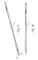
- the handle 40 is preferably molded to a portion of the outer tubular member 50, which extends from the handle 40 to the distal tip 60 of the device 10.
- the outer tubular member 50 is disposed about the inner tubular member 30.
- the outer tubular member 50 is clear so that the inner tubular member 50 is visible there through.
- markers 80-84 preferably formed on portions of the inner tubular member 30 are also visible through the outer tubular member 50.
- the stent-retaining hub 70 in the distal region 54 of the device 10, there is a stent-retaining hub 70, which holds the stent (not shown) during the placement procedure.
- the stent-retaining hub 70 comprises two double conical shaped elements, one disposed at each end of the stent and coupled with the inner tubular member 30.
- the distal most double conical shaped element is the distal tip of the device 60.
- the stent-retaining hub 70 may also comprise proximal 72 and distal 74 stops between which the stent rests in its crimped state.
- the stent-retaining hub 70 may be removable so as to allow a pre-sterilized, crimped stent containing, hub 70 to be installed in the distal region of the device for stent delivery and deployment. Moreover, the proximal end of the stent may also be restrained by conventional coupling methods (not shown) to facilitate retrieval if necessary. By way of example, which is in no way to be construed as limiting, a stent having suture disposed about its proximal end may be retained by the stent-retaining hub 70 that has releasable finger-like members engaging the suture.
- the device is configured such that an optional guidewire (not shown) may be passed through the internal diameter 32 of the device through the proximal handpiece 14 at the proximal end, the distal tip 60 at the distal end and the inner tubular member 30 there between.
- the internal diameter 32 of the device 10 is sufficient to receive an optical scope there through.
- the optical scope may pass about the guidewire from the proximal to and through the distal ends of the deployment apparatus 10. This is so as to allow the physician to view a patient's anatomy that may lie distal of the distal tip 60 of the deployment apparatus 10.
- a single fiberscope may be provided that is coupled with the guidewire.
- outer tubular member 50 and the inner tubular member 30 may be adapted so that instead of feeding the optical scope through the proximal handpiece 14, the mating apertures are formed along a portion of the longitudinal expanse of the inner tubular member 30 and an entry point formed on a portion of the outer tubular member so as to receive the scope through both the inner tubular member 30 and the outer tubular member 50 even as the inner tubular member 30 and outer tubular member 50 are moved rotationally and proximally or distally with respect to the other.
- a deployment device is provided that has a distal tip 60 having a light source 160, lens (not shown) and working channel 32 operatively configured therein to allow direct visualization of the target site.
- the present invention in alternative embodiments shown in FIGS. 18-19 , provides deployment devices wherein guidewires optical instruments 120 and other therapeutic tools may be provided through alternative means.
- a guidewire receiving member (not shown) and an optical instrument receiving member (not shown) are provided that allows one or both of these devices to travel to the distal tip 60 of the device 10 via the internal diameter 32 of the inner tubular member 30.
- an optical instrument 120 is coupled with a portion of inner tubular member 30 and extends beyond both the distal and proximal ends thereof.
- the optical instrument 120 may be configured to have an external light source that is connected by the light source connector 126.
- a CCD or Lens is connected to the optical instrument 120 by connector 128.
- the optical device allows for the visual display on conventional display means known in the art.
- the device 10 may also be configured so that the guidewire and/or the optical instrument 120 can pass between the light source connector 126 and the lens connector 128, obtaining access to either the inner tubular member 30 or the outer tubular member 50.
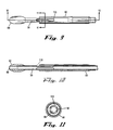
- FIG. 19 Yet another and preferred embodiment of a deployment device in accordance with the present invention is the device 10 as shown in FIG. 19 , wherein the outer tubular member 50 defines a plurality of longitudinally extending utility channels 55 between the inner 56 and outer surfaces 52 of the outer tubular member 50.
- an optical instrument 120, guidewire, or other medical appliance may be disposed through these channels to provide therapeutic results.
- the channels extend longitudinally from the proximal to the distal ends of the outer tubular member 50 and may also themselves define openings (not shown) that allow the preferred medical appliance (e.g., optical instrument, guidewire, etc) to enter the inner tubular member at locations between the distal and proximal ends thereof.
- the openings may be formed through both the inner surface 56 of the outer tubular member 50 and potentially both the inner 32 and outer 34 surfaces of the inner tubular member 30.
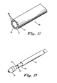
- FIGS. 15-16 & 22 show a deployment device 10 that has an outer tubular member 50 having a plurality of utility channels 55 for passing instruments and devices, useful during a procedure, through the device 10 to the target location.
- distal tip 60 has complementary utility grooves 150 to allow the instruments and devices to pass beyond the distal end of the outer tubular member 50.
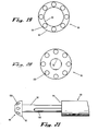
- FIG. 15 also shows the advantage of having optical windows 110 in general and staggered optical windows 110 in particular to optimize visualization proximal the distal tip 60.
- a suitable instrument passed along the utility channels 55 of the outer tubular member 50 and the utility groove 150 of the distal tip 60 would be a guidewire, though many other useful instruments may be employed, limited only by the need to keep the exterior diameter 52 of the outer tubular member 50 within a range that can fit in the lumen in which the device 10 will be introduced.
- the guidewire could be a standard guidewire, or alternatively a specialized ultra thin guidewire having optical capabilities.
- An alternative instrument is a syringe system (not shown) that can be integrally coupled with the delivery and deployment device 10 or alternatively configured to pass through either the working channel 32 or 56 of the inner 30 or outer 50 tubular members, respectively, or the utility channels 55 of the outer tubular member 50.
- An exemplary syringe system may have thermotherapy, cryotherapy, photodynamic, chemotherapy capabilities or combinations of these capabilities. In either configuration, but particularly the chemotherapeutic embodiment, the syringe system provides an extendable/retractable needle for delivering a therapeutic dose of a bioactive product such as a chemotherapeutic agents.
- the needle may alternatively be, for example, an electrocautery probe, for certain thermotherapy indications, or the bioactive product may be a suitable photosensitizer, in certain photodynamic therapy indications. Therefore, in order to adapt to the desired capabilities and a variety of indications, the general syringe system may be adapted in accordance with methods known in the art without requiring undue experimentation. It is preferable, in the chemotherapeutic and/or the photodynamic application, however, that the needle be introduced into a target lesion and the bioactive product introduced. It should be noted that the syringe system is useful in both malignant and benign applications.
- the syringe system comprises a needle at the distal end and a reservoir of bioactive product proximally situated, with a conduit servicing the needle and reservoir there between.
- the syringe system is configured to provide for extension and/or retraction of the needle to a target site in both the stand alone and integrated configurations.
- the stand-alone version is a general reference to the embodiment that is suitable for situating through appropriate channels of the device, but is not coupled thereto.
- the various utility instruments referenced above may take the form of a number of devices but, by way of non-limiting example, an exemplary photodynamic therapy device would have essential features of Patent No. 6,454789B1 to Chen et al. ; an exemplary thermotherapy device would have essential features of Patent No. 6,488,697 to Ariura et al. ; an exemplary cryotherapy device would have essential features of Patent No. 6,514,245B1 to Williams et al. ; and an exemplary electrocautery device would have essential features of Patent No. 6,156,035 to Songer.
- the syringe system may alternatively be configured for sealing a bleb, serving as a vehicle for drug administration or air removal from a bleb, etc. Therefore, it would be within the capacity of one of ordinary skill in the relevant medical device art to adapt such utility instruments for use with or as an integrated component of the present invention without undue experimentation.
- the bioactive product may be a variety of therapeutic substances, but for chemotherapeutic indications, it may comprise a wide variety of chemotherapeutic agents such as but not limited to the exemplary chemotherapeutic agents like cis-platinum, paclitaxol, 5-flourouracial, gemcytobine and navelbine.
- the chemotherapeutic agents are generally grouped as DNA-interactive Agents, Antimetabolites, Tubulin-Interactive Agents, Hormonal agents and others such as Asparaginase or Hydroxyurea. Each of the groups of chemotherapeutic agents can be further divided by type of activity or compound.
- chemotherapeutic agents used in combination with the anti-cancer agents or benzimidazoles of this invention include members of all of these groups.
- chemotherapeutic agents and their method of administration see Dorr, et al, Cancer Chemotherapy Handbook, 2d edition, -pages 15-34, Appleton & Lange (Connecticut, 1994 ).
- DNA-Interactive Agents include the alkylating agents, e.g. Cisplatin, Cyclophosphamide, Altretamine; the DNA strand-breakage agents, such as Bleomycin; the intercalating topoisomerase II inhibitors, e.g., Dactinomycin and Doxorubicin); the nonintercalating topoisomerase II inhibitors such as, Etoposide and Teniposide; and the DNA minor groove binder Plicamycin.
- the alkylating agents form covalent chemical adducts with cellular DNA, RNA, and protein molecules and with smaller amino acids, glutathione and similar chemicals.
- these alkylating agents react with a nucleophilic atom in a cellular constituent, such as an amino, carboxyl, phosphate, or sulfhydryl group in nucleic acids, proteins, amino acids, or glutathione.
- a nucleophilic atom such as an amino, carboxyl, phosphate, or sulfhydryl group in nucleic acids, proteins, amino acids, or glutathione.
- Typical alkylating agents include: Nitrogen mustards, such as Chlorambucil, Cyclophosphamide, Isofamide, Mechlorethamine, Melphalan, Uracil mustard; aziridines such as Thiotepa; methanesulfonate esters such as Busulfan; nitroso ureas, such as Cannustine, Lomustine, Streptozocin; platinum complexes, such as Cisplatin, Carboplatin; bioreductive alkylator, such as Mitomycin, and Procarbazine, dacarbazine and Altretamine; DNA strand breaking agents include Bleomycin; DNA topoisomerase II inhibitors include the following: Intercalators, such as Amsacrine, Dactinomycin, Daunorubicin, Doxorubicin, Idarubicin, and Mitoxantrone; nonintercalators, such as Etoposide and Teniposide.
- the DNA minor groove binder is Plica
- the Antimetabolites interfere with the production of nucleic acids by one or the other of two major mechanisms. Some of the drugs inhibit production of the deoxyribonucleoside triphosphates that are the immediate precursors for DNA synthesis, thus inhibiting DNA replication. Some of the compounds are sufficiently like purines or pyrimidines to be able to substitute for them in the anabolic nucleotide pathways. These analogs can then be substituted into the DNA and RNA instead of their normal counterparts.
- the Antimetabolites useful herein include: folate antagonists such as Methotrexate and trimetrexate pyrimidine antagonists, such as Fluorouracil, Fluorodeoxyuridine, CB3717, Azacytidine, Cytarabine, and Floxuridine purine antagonists include Mercaptopurine, 6-Thioguanine, Fludarabine, Pentostatin; sugar modified analogs include Cyctrabine, Fludarabine; ribonucleotide reductase inhibitors include Hydroxyurea.
- folate antagonists such as Methotrexate and trimetrexate pyrimidine antagonists, such as Fluorouracil, Fluorodeoxyuridine, CB3717, Azacytidine, Cytarabine, and Floxuridine purine antagonists include Mercaptopurine, 6-Thioguanine, Fludarabine, Pentostatin
- sugar modified analogs include Cyctrabine, Fludarabine
- Tubulin Interactive agents act by binding to specific sites on Tubulin, a protein that polymerizes to form cellular microtubules. Microtubules are critical cell structure units. When the interactive agents bind on the protein, the cell cannot form microtubules Tubulin Interactive agents include Vincristine and Vinblastine, both alkaloids and Paclitaxel.
- Hormonal agents are also useful in the treatment of cancers and tumors. They are used in hormonally susceptible tumors and are usually derived from natural sources. These include: estrogens, conjugated estrogens and Ethinyl Estradiol and Diethylstilbestrol, Chlorotrianisene and Idenestrol; progestins such as Hydroxyprogesterone caproate, Medroxyprogesterone, and Megestrol; androgens such as testosterone, testosterone propionate; fluoxymesterone, methyltestosterone; Adrenal corticosteroids are derived from natural adrenal cortisol or hydrocortisone. They are used because of their anti-inflammatory benefits as well as the ability of some to inhibit mitotic divisions and to halt DNA synthesis. These compounds include Prednisone, Dexamethasone, Methylprednisolone, and Prednisolone.
- Leutinizing hormone releasing hormone agents or gonadotropin-releasing hormone antagonists are used primarily the treatment of prostate cancer. These include leuprolide acetate and goserelin acetate. They prevent the biosynthesis of steroids in the testes.
- Antihormonal antigens include antiestrogenic agents such as Tamosifen, antiandrogen agents such as Flutamide; and antiadrenal agents such as Mitotane and Aminoglutethimide. Hydroxyurea appears to act primarily through inhibition of the enzyme ribonucleotide reductase. Asparaginase is an enzyme that converts asparagine to nonfunctional aspartic acid and thus blocks protein synthesis in the tumor. It should also be noted that the bioactive product may include as much as about 99.9% chemotherapeutic agent to as little as ⁇ 1% chemotherapeutic agent or any amount there between.
- the distal region 54 of outer tubular member 50 may be beveled to allow a portion 66 of distal tip 60 to be covered by a portion of outer tubular member 50 without obstructing either the utility channels 55 of the outer tubular member 50 or the utility grooves 150 on the distal tip 60.
- the distal tip 60 may be beveled to receive the distal most portion of the outer tubular member 50.
- FIG. 19-21 shows an alternative embodiment of device 10 wherein the distal tip 60 has a substantially flat proximal face that can abut the distal face of the outer tubular member 50. Additionally, in either the closed (abutted) or open configurations, instruments can freely pass through the utility channels 55 of the outer tubular, member 50 and the utility channels 152, which are formed through distal tip 60 to complement the utility channels 55 of the outer tubular member 50.
- one or more of the utility channels 55 and 152 themselves may be optical fibers or bundles of optical fibers allowing for direct visualization distal, proximal and through the delivery and deployment device 10.
- the utility grooves 150 may also have internally and/or externally facing optical components.
- the inner surfaces 32 and 56 of the inner 30 and outer 50 tubular members (working channels) may themselves comprise optical characteristics and/or be formed of optical material. Therefore, reference throughout, including in the appended claims, to optical capabilities in the these components refers to either inherent capacity of the component material or capacity provided by adoptively introduced optical components or both.
- FIG. 1 a deployment apparatus 10 that includes an elongate and flexible outer tubular member 50 constructed of at least one biocompatible thermoplastic elastomer, e.g. such as polyurethane and nylon, typically with an outside diameter 52 in the range of about between 6-9 mm.
- a central lumen 56 runs the length of the outer tubular member 50.
- a distal region 54 of the outer tubular member 50 surrounds the stent to be placed (not shown), and maintains the stent in a crimped delivery configuration, against an elastic restoring force of the stent.
- the stent when in a normal unrestrained configuration, generally has a diameter (for example, 10-20 mm) substantially larger than the interior diameter 32 of the inner tubular member 30.
- the expanded stent is larger in diameter than the body lumen in which the stent is fixed, and the restoring force tends to maintain the stent against the tissue wall.
- Outer tubular member 50 is mounted at its proximal end to a handle 40. Outer tubular member 50 can be pushed and pulled relative to inner tubular member 30 by hand manipulation of the handle 40 at the proximal end of the outer tubular member 30 and holding the proximal end of the handle 40.
- a guidewire is preferably disposed within the interior lumen 32 of an elongate and flexible inner tubular member 30, which can be constructed of materials similar to those employed to form the outer tubular member 50. However, it is preferable that inner tubular member 30 is formed from a more durable material and additionally no guidewire may be necessary.
- a distal tip 60 is coupled with inner tubular member 30 about the distal end thereof. Also attached to the inner tubular member 30 are a proximal marker 80, at least one medial marker 82 and a distal marker 84.
- the markers are constructed of a radiopaque material e.g. platinum iridium, and surround the inner tubular member 30.
- Markers 80, 82 and 84 are axially spaced apart to mark the length of the stent and to mark the critical deployment distance for that stent length.
- the markers identify a stent-retaining hub 70 of the inner tubular member 30, more particularly the distal region of the inner tubular member 30 is surrounded by a stent (not shown).
- Markers 80 and 84 have Exterior Diameters slightly smaller than the interior diameter of outer tubular member 50.
- the inner tubular member 30 thus functions as a carrier for the stent, with outer tubular member 50 providing a retaining means for radially compressing the stent and maintaining the stent along the stent-retaining hub 70, so long as the outer tubular member 50 surrounds the stent.
- the markers may be more or fewer in number and may also be formed about the interior diameter 32 of the inner tubular member 30 or alternatively, about the interior diameter 56 or exterior-diameter 58 of the outer tubular member 50.
- Inner tubular member 30, along its entire length, has an inferior lumen 32 open to both the proximal and distal ends of the inner tubular member 30.
- An axial passage 68 through distal tip 60 continues lumen 32 to allow the guidewire 12 to pass from the proximal handpiece 14 through the distal tip 60.
- Handle 40 and outer tubular member 50 are movable relative to inner tubular member 30. More particularly, the handle 40 is moved proximally relative to the stent-retaining hub 70, facilitating the movement of outer tubular member 50 relative to inner tubular member 30 so as to provide a means for controllably withdrawing the outer tubular member 50, relative to the inner tubular member 30, resulting in the release of the stent for radial self-expansion.
- the initial step is to position a guidewire (not shown) within the anatomy of a patient. This can be accomplished with a guide cannula (not illustrated), leaving guidewire in place, with the exchange portion of the guidewire extended proximally beyond the point of entry into the anatomy of the patient.
- Deployment apparatus 10 is then advanced over the guidewire 12 at the exchange portion, with the guidewire being received into passage 68 of distal tip 60. As device 10 is inserted into the body, the proximal portion of guidewire travels proximally (relative to the device) to the proximal end of guidewire lumen 32.
- the physician maintains the guidewire and inner tubular member 30 substantially fixed with one hand, while moving handle 40 in the proximal direction with the other hand, thus to move outer tubular member 50 proximally relative to inner tubular member 30.
- the stent remains substantially fixed relative to inner tubular member 30, and thus radially self-expands.
- the handle 40 and correspondingly the outer tubular member 50 are retracted, the handle 40 encounters a safety mechanism for the critical deployment point.
- the inner tubular member 30, via the handle 40 may have to be rotated to align and insert the stop 20 into the handle 40. When fully inserted, further deployment cannot occur without twisting and snapping the tab 24 portion of the stop 20. Continued retraction of the outer tubular member 50 results in complete deployment of the stent.
- the stent After deployment, the stent ideally radially self-expands to a diameter greater than the diameter of outer tubular member 50. Accordingly, device 10 can be withdrawn proximally through the stent. However, in the event that the stent does not radially expand fully, distal tip 60 is configured to facilitate removal of deployment apparatus 10 through the lumen of the stent.
- the guidewire can be withdrawn as well.
- the guidewire emerges from the proximal end of the proximal handpiece 14.
- the deployment apparatus 10 can be removed without removing the guidewire.
- Device 10 is removed by progressively pulling the device away from the guidewire (which removes the guidewire from within the inner tubular member 30), all while maintaining the guidewire in place.
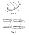
- distal tip 60 can have a variety of confirmations, but by way of non-limiting example, distal tip 60 comprises first 62 and second 66 ends having a smaller diameter than the medial region 64 thereof.
- each end is conical in shape so as to allow the tip 60 to wedge through an Incompletely expanded stent when pulled proximally with respect to the stent.
- the dual conical end design facilitates removal but sufficiently prevents the crimped stent from releasing from the stent-retaining hub 70 and prematurely expanding.
- Distal tip 60 may alternatively have a flared medial region 64 so as to facilitate retrieval and retraction of a misaligned stent 12.
- the device 10 has a deployment safety mechanism that comprises male 46 and female 22 locking members that are brought into functional engagement as the stent is being deployed. Once the stent has reached the critical deployment point, the distal end of the stop 20 is substantially flush with the base 44 of the handle cavity 42 and the female locking members 22 of the stop 20 are in operative communication with the corresponding male locking members 46 formed on the interior surface of the cavity 42 of the handle.
- the safety mechanism is engaged as described above, the stent cannot be deployed further without physician intervention. In order to deploy the stent beyond this point, the physician has to rotate the stop 20 to cause the tab 24 to break. Once the tab 24 is broken, the device 10 is in the proceed orientation and deployment may proceed.
- This safety mechanism is in contrast to locks that merely serve as a stabilizer to prevent movement of the tubes during a procedure.
- the physician will feel a tactile indication that the device 10 can be deployed further.
- the breaking of the tab may also, or as a substitute to tactile indication, results in an audible indication that further deployment is possible.
- the physician is apprised of the fact that deployment beyond this point is irreversible except for interventional retrieval methods.
- the critical deployment point is preferably about 60% deployment, beyond which retraction is not recommended.
- the safety mechanism removes the need to estimate the extent of deployment and provides a reliable means of accurately deploying stents.
- Alternative locking mechanisms may be provided as long as they retain the important characteristic of giving the physician a sensory indication of extent of stent deployment and removes the need to estimate extent of deployment.
- the locking mechanism could comprise a breakable seal, tab/stop lock, diverted channel safety mechanism, etc.
- FIG. 12 An arrangement outside the scope of the present invention is shown in FIG. 12 , (also shown in FIGS 7 and 8 ); which a diverted channel safety mechanism is provided generally as 118.
- a detent 90 is coupled with the hypotube 16.
- a catch 144 comes into contact with a base of the safety track 142 of the handle.
- the handle in this arrangement, defines a substantially Z shaped channel 142.
- the shape of the channel 142 may vary from an L, S, T or other suitable shape for encouraging user intervention.
- physician intervention comprises the step of rotating the hypotube 16 such that the detent 144 no longer abuts the catch 144 of the brack 142. Rather, once rotated, the catch 144 allows free stent deployment.
- the point of detênt/base interaction is about approximately the critical deployment point.
- the inner tubular member 30 defines at least one aperture there through to facilitate viewing with an optical instrument.
- the aperture(s) generally referred to as optical window 110 are preferably beveled, as shown in FIG. 11 , to maximize the viewing area available to the optical scope.
- the optical windows 110 may be offset or staggered so that at different deployment depths, there is an available optical window 110.
- these optical windows 110 are preferably oval, but may be any number of geometrical shapes such as a polygon, spherical, etc.
- the device 10 may have longer or shorter overall dimensions depending on the deployment protocol.
- radial pressure exerted by the bleb stent against the interior surface 56 of the outer tubular member 50 provides sufficient resistance to keep the stent in place prior to deployment.
- the outer tubular member 50 can be retracted to fully deploy the stent.
Abstract
Description
- The present invention relates generally to medical devices directed to the prevention of nonvascular vessel or passageway occlusion, and more particularly to stent deployment apparatuses and methods for utilizing these devices.
- Self-expanding stents are valuable prostheses for keeping lumen open and preventing closure due to a stricture, external compression, or internal obstruction. In particular, stents are commonly used to keep blood vessels open in the coronary arteries and they are frequently inserted into the ureters to maintain drainage from the kidneys, the bile duct for pancreatic cancer or cholangiocarcinoma or the esophagus for strictures or cancer. Additionally, stents may be formed specifically for alternative indications such as sealing a bleb, serving as a vehicle for drug administration or air removal from a bleb, etc.
- Though stents are excellent devices when used properly, improper installation can lead to tissue luminal inflammation and tissue granulation. In particular, many physicians introduce stents with catheters and other delivery devices that do not give them adequate visual certainty that the device has been installed at the desired target site. Moreover, devices that allow for limited visual feedback have an excessively large diameter, which can hinder patient ventilation. Additionally, such devices do not have safety features to ensure that the stent is not prematurely and irretrievably deployed.
- In order to facilitate the delivery of stents, medical device companies began to design deployment apparatuses that allow physicians to deploy stents more precisely.
-
EP-A-0364420 describes a device for transluminal implantation or extraction that includes a central tube (3) that is axially displaceable with respect to an outer tube (5). The central tube includes spring members (21) that are configured to compress the proximal end of the stent into engagement with the central tube. The outer tube may be moved axially forward such that the entire stent is compressed therein. - Unfortunately, guidance of the stent has substantially remained a function of physician skill resulting from substantial practice. This fact has become particularly evident with the advent of radially expanding stents. If after full deployment of the stent, the physician discovers the stent has been implanted incorrectly, there is no conventional way of correcting the error short of removing the stent. In particular, as a rule of thumb, once the exterior catheter, of conventional delivery devices, has been retracted beyond 60%, it generally cannot be realigned with respect to the stent. As a result, physicians must be sure of their stent placement prior to deploying the stent beyond the 60% point. We will refer to-this-60%- point throughout the application-as the critical deployment point. Conventional stent delivery devices, however, do not have any safety mechanism to prevent excessive deployment of a misaligned stent. In fact, conventional delivery devices require the physician to estimate extent of deployment, which results in either overly conservative or excessive deployment -- both of which leads to stent misplacement.
- Misplacement is often a function of a physician's inability to directly visualize the target area and the route thereto. Attempts have been made to provide scopes as postscript additions to existing devices, with little or no thought about the functionality of such arrangements. As a result visualization features are not directly integrated into the design of these devices and therefore substantially limit their efficacy.
- An additional limitation of conventional stent delivery devices is the distal tip of conventional stent delivery devices are not adequately designed to (1) facilitate the clearance of obstructed lumen, or (2) facilitate the removal of the delivery device once the stent is radially expanded. In particular, most distal tips are not configured to comfortably guide the delivery device through a diseased or occluded lumen so that the stent can be delivered in the most beneficial location. Moreover, once the stent is radially expanded conventional designs rely exclusively on dimensional mismatching to ensure proper removal of the delivery device. In the event the stent does not adequately expand to preset dimensions, a conventional delivery device would be stuck in the patient until some invasive procedure is performed to remove it and the defective stent.
- Therefore, there remains an existing need for a stent deployment apparatus that has a safety mechanism to prevent excessive deployment of a misaligned stent. Preferably it would be desirable if the safety mechanism had a physical and/or audible indication means to inform the physician when she has reached maximum reversible deployment. As an additional safety feature, there is an existing need for a distal tip designed to allow for the removal of the deployment apparatus even if the stent does not radially expand to its preset expansion diameter. An existing need also exists for a stent deployment apparatus that has a distal tip adequately configured to navigate through diseased and/or occluded lumens so that the stent can be delivered to this target area.
- There also remains an existing need for a stent deployment apparatus that increases physician control during stent deployment.
Moreover, there exists a need for a stent deployment apparatus that allows for the insertion of an optical scope to facilitate stent delivery. In particular, there is an existing need for a delivery device that allows for the direct visualization of lumens via a variety of optical configurations. For example, optical scopes can be directly integrated into the inner dimensions of the device or receivable about the inner or outer dimensions of the inner and outer tubular members. Additionally, there is a need for a device that provides visualization windows to enhance the physician's field of view during deployment. -
US-A5954729 discloses the preamble of claim 1. - It is a principal objective of a stent deployment apparatus in accordance with claim 1 or claim 2 to provide a device that can facilitate the precise delivery of stents in a safe and repeatable fashion. In the furtherance of this and other objectives, the deployment apparatus allows the physician to concentrate on correct placement without having to estimate extent of deployment. In particular, the present deployment apparatus has a physical safety mechanism that limits deployment to the critical deployment point (i.e., -60%). The critical deployment point may range from 5% to 95% but is preferably about 60%. At this point, if the physician is satisfied with placement, she can engage the safety means to what we refer to as the Proceed Orientation (PO) and fully deploy the stent. It is preferred that when the safety mechanism is engaged to the PO, a physical twist and a possible audible indicator sounds to inform the physician that if she deploys the stent any further, she can no longer retract the stent beyond this point. Though the present stent and delivery system eliminates the need for repositioning, such safety features are still preferable. In a preferred embodiment, the slight audible indication is the sound of a tab or stop snapping to allow free deployment of the stent.
- An additional objective of the present invention is to provide a stent deployment apparatus where the handle portion is held and the outer tubular member of the device is retracted.
- Yet another objective in accordance with the present invention is to provide a deployment apparatus having a distal tip designed to facilitate the clearance of obstructed lumen. In the furtherance of this and other objectives, the exemplary distal tips are configured to comfortably guide the deployment apparatus through a diseased or occluded lumen so that the stent can be delivered in the most beneficial location.
- Still another objective of the deployment apparatus according to claim 1 is to provide a distal tip that facilitates the removal of the deployment apparatus once the stent is radially expanded. In the furtherance of this and other objectives, the distal tip is designed to clear the stent during removal, in the event the stent does not adequately expand to preset dimensions. In a preferred embodiment, removal is facilitated by providing a distal tip that has a substantially bidirectional conic shape. This allows for the removal of the present deployment apparatus, while conventional deployment apparatuses would be stuck in the patient until some invasive procedure was performed to remove it and the defective stent. This results from the fact that conventional deployment apparatus designs rely exclusively on dimensional mismatching between the distal tip and the radially expanded stent to ensure proper removal of the deployment apparatus. As a function of the design of the present invention, the compressed stent is adequately retained in place and does not prematurely creep up the proximally facing conic end of the distal tip and prematurely deploy.
- An additional objective of the present invention is to provide a stent deployment apparatus that allows for the insertion of an optical scope to facilitate stent delivery. In the furtherance of this and other objectives, the device is capable of letting a flexible optical scope of about 5-6 mm diameter be coupled along the exterior of the outer tubular member thereof. Alternatively, it is envisioned that an ultra thin optical scope may pass along side the guidewire through the internal diameter of the inner tubular member of the device. In the furtherance of this and other objectives, the inner tubular member defines windows in the distal region to allow enhanced visualization of stent deployment. In accordance with this embodiment, the guidewire itself may be the scope.
- An additional objective in accordance with an alternative embodiment of the present invention is to provide a stent deployment apparatus that has an outer tubular member of sufficient cross sectional thickness to define a plurality of longitudinally extending channels for receiving additional utility tools. In the furtherance of this and other objectives, and by way of example only, one such channel could accommodate an ultra thin scope while an alternative channel receives a guidewire, syringe systems, etc. Principally, these channels are suitable for receiving a number of other tools that a physician may need during deployment of a stent or therapeutic treatment of target tissue.
- Still another objective in accordance with a preferred embodiment of the present invention is to provide a device having direct visualization capabilities directly incorporated into the device. In one design of such embodiment, the inner tubular member in general and the distal tip in particular serve as an optical device. Moreover, in embodiments where the outer tubular member and distal tip have utility channels and/or grooves, the channels and grooves may themselves be comprised in whole or in part by optically active materials. In the furtherance of this and other objectives, the internal tubular member comprises at least one optical fiber coupled to a lens and light source to provide direct visualization during deployment. Though the above specified safety mechanism is not necessary with direct visualization, the safety mechanism may accompany this embodiment.
- In addition to the above objectives, an exemplary stent deployment apparatus preferably has one or more of the following characteristics: (1) applicable for tracheal respiratory bronchial stenosis; (2) biocompatible; (3) compliant with radially expanding stents; (4) capable of distal or proximal stent release; (5) smooth and clean outer surface; (6) length of the device variable according to the insertion procedure to be employed; (7) outer dimension as small as possible (depends on the diameter of crimped stent); (8) dimensions of the device must offer enough space for the crimped stent; (9) radiopaque markers, preferably on the inner tubular member, to indicate proximal and distal ends of the stent; (10) sufficient flexibility to adapt to luminal curvatures without loss of ability to push or pull; (11) low friction between the inner tubular member and outer tubular member; (12) sufficient resistance to kinking; (13) good deployment, ability to reposition partially deployed stent; (14) added with a scale to observe the stent position during the insertion procedure; (15) insertion procedure should require low force; or (16) sufficiently economical to manufacture so as to make the deployment apparatus disposable.
- The invention according claim 36 comprises use of a device according to claim 7.
- Further objectives, features and advantages of the invention will be apparent from the following detailed description taken in conjunction with the accompanying drawings.
-
-
FIG. 1 is a perspective view of a device for delivering and deploying a radially self-expanding stent in accordance with the present invention; -
FIG. 2 is a side view of the device for delivering and deploying a radially self-expanding stent in accordance with the present invention. -
FIG. 3A depicts enlarged views of portions of the deployment safety mechanism alonglines 3A-3A of the device ofFIG. 2 -
FIG. 3B shows a cross section view of the deployment safety mechanism alonglines 3B-3B ofFIG. 3A ; -
FIG. 3C is a perspective view of a portion of the complementary portion of the deployment safety mechanism region of the handle as shown alonglines 3C-3C ofFIG. 3A ; -
FIG. 3D is a perspective view of the stop of the deployment safety mechanism as shown alonglines 3C-3C of the device ofFIG. 3A . -
FIG. 4A is a side perspective view of the distal region of the device ofFIG. 2 , alonglines 4A-4A; -
FIG. 4B depict an enlarged sectional view of the distal region of the device ofFIG. 2 , alonglines 4B-4B; -
FIG. 5 is an enlarged sectional view of a distal tip with direct visualization capabilities, in accordance with the present invention, showing the lens, light source and working channel portions thereof; -
FIG. 6 depicts cross sectional views of various distal tips in accordance with the present invention; -
FIG. 7 is a perspective view of an alternative device for delivering and deploying a radially self-expanding stent, not in accordance with the present invention; -
FIG. 8 is a side view of the device ofFIG. 7 for delivering and deploying a radially self-expanding stent; -
FIG. 9 is a side view of the distal region of a device for delivering and deploying a radially self-expanding stent in accordance with the present invention; -
FIG. 10 depicts an enlarged cross sectional view of portions of the deployment visualization features along lines 10-10 of the device ofFIG. 9 ; -
FIG. 11 shows a frontal view of the visualization features along lines 11-11 ofFIG. 9 ; -
FIG. 12 is a perspective view of a portion of a deployment safety mechanism ofFIG. 7 ; -
FIG. 13 is a perspective view of the slide cavity of the safety mechanism as shown along lines 13-13 of the device ofFIG. 12 ; -
FIG. 14 is a perspective view of a portion of a deployment safety mechanism as shown along lines 14-14 ofFIG. 12 ; -
FIG. 15 is a perspective view of a portion of a device for delivering and deploying a radially self-expanding stent having optical windows that are staggered in orientation and wherein the distal tip has channels formed on the outer surface thereof to facilitate the ingress and egress of utility tools passed through the outer tubular member, -
FIG. 16 is a perspective view of a preferred embodiment of a deployment apparatus showing a variety of optional geometries of the working channels formed between the interior and exterior diameters of the outer tubular member. -
FIG. 17 is a sectional view of the deployment apparatus shown inFIG. 15 . -
FIG. 18 is a perspective view of a deployment apparatus, as shown inFIG. 15 , including the safety mechanism ofFIG. 12 that is not in accordance with the present invention, and further comprising a parallel channel for receiving and extending a guidewire; -
FIG. 19 is a cross sectional view of an outer tubular member in accordance with a preferred embodiment of the present invention wherein the outer-tubular member defines a plurality of longitudinally extending apertures between the inner and outer surfaces thereof forming utility channels; -
FIG. 20 is a frontal view of the distal tip showing apertures complementary to the utility channels shown inFIG. 19 ; -
FIG. 21 is a side view of a preferred embodiment of a device for delivering and deploying a radially self-expanding stent featuring an alternative distal tip, as shown inFIG. 20 and visualization windows; -
FIG. 22 is a perspective view of a preferred embodiment of a delivery and deployment device in accordance with the present invention, wherein the distal tip has utility grooves and the outer tubular member has a substantially beveled distal region for receiving the proximal end of the distal tip. - A general problem in the diagnosis and therapy of pulmonary defects, bronchial defects, tracheal defects and many other nonvascular anomalies is the fact that the instruments must be inserted from the mouth or the nose into the larynx or the trachea, wherein it is necessary to pass the area of maximum diameter of about 15 mm. As a result, the inserted instruments take away a very large portion of the free lumen. Consequently, in respiratory lumens spontaneous respiration of the patient is impaired. In addition, there is the danger of injuring the patient.
- Therefore, it is a principal objective of the present invention to provide an instrument, which can be inserted gently, ensures a good utilization of the available space and makes it possible to carry out active therapeutic measures, wherein the instrument is to be particularly suitable for the introduction-and placement of stents. It is also within the scope of the present invention to provide a device adaptable for placement in a variety of target sites in a patient's anatomy. In other words, devices in accordance with the present invention should in no way be limited to pulmonary delivery devices as such devices are suitable for a broader range of indications.
- A preferred embodiment of the present deployment apparatus comprises inner and outer tubular members interactively coupled with each other in a manner that one can move rotationally and proximally or distally with respect to the other. The tubular members are preferably nonpyrogenic. In order to deliver the stent, the deployment apparatus comprises a distal tip and a stent-retaining hub, between which the stent is placed. The distal tip and the stent-retaining hub are both functionally coupled with the inner tubular member. The inner tubular member terminates with the proximal handpiece. The proximal handpiece is preferably a female threaded proximal handpiece, but alternative termini are within the skill of the stent deployment device engineer. In fact, a suitable alternative would be a handle having similar internal diameter characteristics as the proximal handpiece while providing greater surface area for manipulating the deployment apparatus. The deployment apparatus is preferably sterilized by a validated sterilization cycle EtO. Moreover, the device is capable of resterilization (validated cycle) with no degradation of performance. However, it is preferable to provide a disposable device.
- The total length of the deployment apparatus varies based on the location of the target lumen. For purposes of this discussion, the usable length of the inner tubular member shall be from the inner tubular member distal hub/handle end to the distal tip. The usable length of the outer tubular member shall be from the distal hub/handle end of the outer tubular member to the distal tip. The overall length of the device shall be from the distal hub/handle end of the outer tubular member to the distal tip of the inner tubular member when assembled and not deployed. There are preferably three radiopaque (platinum iridium) markers for marking the stent, the stent deployment distance, and depth. The outer tubular member is preferably manufactured of stiffer synthetic material. In a preferred embodiment, the length of the outer tubular member is preferably shorter than that of the inner tubular member.
- However, these dimensions may differ as a function of the stent diameter and/or if an optical scope is integrally provided to facilitate stent delivery. The outer tubular member may be configured to allow for the coupling of an optical stent along the exterior diameter thereof. Alternatively, the interior diameter of the inner tubular member may be enlarged sufficiently to accommodate the optical scope and additionally the increased crimped stent diameter. However, it is expected, though not required, that the smallest diameter that allows for example a bronchoscope to pass will be employed in this alternative embodiment. It should be understood that through hindsight, after exposure to the present specification, one of ordinary skill would be able to adapt the current device to receive an ultra thin optical scope to the internal diameter of the device without undo experimentation.
- In an alternative embodiment, an integrated direct visualization system is provided wherein an optical cable is coupled with a portion of or comprises the hypotube and preferably capable of extending beyond both the distal and proximal ends of the deployment device such that-viewing of-any segment of the lumen is possible. In such embodiments, the camera and light source are preferably operatively coupled and disposed about the distal region of the apparatus.
- An exemplary deployment apparatus in accordance with the present invention is durable while affording adequate flexibility to navigate through anatomical lumens without kinking. To this end, it is preferable that the deployment apparatus is formed of biocompatible synthetics and in a preferred embodiment reinforced with metal structure. This allows for deployment within an accuracy of about ± 3 mm. Moreover, the stent is preferably released with a force lower than 30 Newtons at 37°C.
- The inner tubular member is composed of a thin elastic synthetic material, such as polyurethane or Teflon®. At its proximal end, the inner tubular member has a standard adaptor or connector. At its distal end, the inner tubular member is equipped with a tip specific for various anatomical lumens.
- The inner tubular member and the outer tubular member can be displaced relative to each other in longitudinal direction as well as in a radial direction. The deployment apparatus in accordance with the present invention can be used most advantageously for the placement of stents. Such stents are available in various embodiments of metal and/or synthetic material. They usually are composed of a fabric of metal wires, which expand by themselves as a result of their natural tension. Stents of a so-called shape memory alloy are also known. These stents have a small radial diameter at a low temperature, while they expand radially when exceeding an upper threshold temperature, so that they can keep a stenosis open in this manner. It is particularly advantageous to use stents of an alloy of nickel and titanium, the so-called nitinol.
- An exemplary deployment apparatus according to the present invention can be used for the placement of various stents, whether they are self-expanding stents or stents, which require activation. For this purpose, the stent is placed in the free space between the outer tubular member and the inner tubular member. Positioning of the stent in the deployment apparatus can be carried out in the area between the tip and the stent-retaining hub at the distal end of the inner tubular member. Alternatively, in its insertion position, fasteners or other suitable retaining elements may hold the stent.
- In relevant embodiments, when the stent is inserted and after the stenosis has been passed, the outer tubular member is retracted, so that the stent is released. Alternatively, the distal end of the outer tubular member may be placed about the stenosis so that the inner tubular member may be extended so that the stent is placed in direct contact with the desired location prior to expansion. A self-expanding stent then by itself assumes the expanded position. This eliminates the need for post expansion positioning techniques. With an alternative embodiment of the device, the device has fasteners that retain contact with a portion of the stent in the event that the stent needs to be retracted or repositioned. A stent suitable for such procedures would be one in accordance with the disclosure in copending U.S. Patent Application Serial No. 10/190,770.
- The following reference numbers and corresponding stent placement and deployment device components are used when describing the device in relation to the figures:
- 10
- Stent Delivery & Deployment Device
- 14
- Proximal Handpiece
- 16
- Hypotube
- 20
- Stop
- 22
- Female Locking Member on the Stop
- 24
- Tab of the Stop
- 30
- Inner Tubular Member
- 32
- Interior Diameter of Inner Tubular Member (Working Channel)
- 34
- Exterior Diameter of Inner Tubular Member
- 40
- Handle
- 42
- Cavity in Proximal Portion of Handle
- 44
- Base of Handle Cavity
- 46
- Male Locking Member
- 48
- Inner Handle Hub
- 49
- Outer Handle Hub
- 50
- Outer Tubular Member
- 52
- Exterior Diameter of Outer Tubular Member
- 54
- Distal Region of Outer Tubular Member
- 55
- Utility Channels of Outer Tubular Member
- 56
- Interior Diameter of Outer Tubular Member
- 60
- Distal Tip
- 62
- First End of the Tip
- 64
- Medial Region of the Tip
- 66
- Second End of the Tip
- 70
- Retaining Hub
- 72
- Distal Region of Retaining Hub
- 74
- Proximal Hub of Retaining Hub
- 76
- Pusher
- 80
- Proximal Marker
- 82
- Medial Marker(s)
- 84
- Distal Marker
- 110
- Beveled Optical Window
- 126
- Optical Instrument Light Source Connection
- 128
- Optical Instrument Lens Connector
- 130
- Guidewire Receiving Member
- 140
- Outer Tube
- 142
- Safety Track
- 144
- Safety Catch
- 150
- Utility Grooves of Distal Tip
- 152
- Utility Channels of Distal Tip
- 160
- Light Source
- 180
- Camera
- It should also be pointed out at the outset that various embodiments of stent delivery and deployment devices in accordance with the present invention make reference to guidewires and/or optical instruments. In some embodiments the terms may overlap since it is contemplated within the scope of such embodiments that the guidewire itself has visualization capabilities resulting from the guidewire being an ultra thin optical and/or ultrasound device. It should also be evident from the following disclosure that independent placement of traditional and visualization capable guidewires as well as guidewires integrally coupled with the device for placement and deployment of a stent is contemplated and should be considered as residing within the scope of the claims.
- The figures show an exemplary placement and
deployment device 10. Referring in particular toFIGS. 1-2 , the present invention provides astent deployment apparatus 10 that includes anouter tubular member 50 and aninner tubular member 30, wherein the outertubular member 50 and theinner tubular member 30 can be displaced relative to each other. At the proximal end of anexemplary device 10 is aproximal handpiece 14, coupled with a portion of theinner tubular member 30 and preferably a portion of ahypotube 16. Note that the hypotube throughout this specification may refer to a standard catheter hypotube or alternatively a single or bundle of optical fiber for use in the direct visualization embodiments in accordance with the present invention. As stated earlier, a suitable alternative terminus may be employed as long as it provides the minimum benefits provided by a proximal handpiece. Thehypotube 16 is disposed about theinner tube 30 and extends from a location adjacent to theproximal handpiece 14 through a portion of thehandle 40 of thedeployment apparatus 10. In an alternative embodiment, thehypotube 16 terminates within theproximal handpiece 14. A safety mechanism is provided that is formed in part by the complementary fitting of a portion of thehandle 40 and astop 20 coupled with thehypotube 16 between theproximal handpiece 14 and thehandle 40. Thestop 20 is preferably molded onto thehypotube 16, the molding process resulting in atab 24 formed on thestop 20 that is subsequently broken when the physician desires to place thedeployment apparatus 10 in the proceed orientation. In an exemplary embodiment, when thetab 24 is broken and thedeployment apparatus 10 is placed in the proceed orientation; thestop 20 may potentially rotate freely about thehypotube 16. - As illustrated in
FIGS. 3A-3D , apreferred stop 20 includesfemale locking members 22 comprising channels formed along the exterior thereof that are complementary to themale locking members 46 formed on theinterior cavity 42 in the proximal region of thehandle 40. Themale locking members 46 andfemale locking members 22 can be formed into any shape or suitable size as long as they do not depart from the essential purpose of forming a safety mechanism. Thecavity 42 of thehandle 40 is designed to receive thestop 20 and prevent further deployment. As a result, thestop 20 is molded at a distance along thehypotube 16 such that the distance between the distal end of thestop 20 and thebase 44 of thecomplementary cavity 42 of thehandle 40 roughly corresponds to the critical deployment point. It should be noted that thefemale locking members 22 andmale locking members 46 of the safety mechanism 18 might be reversed so that thefemale locking members 22 andmale locking members 46 are on thehandle 40 and thestop 20, respectively. Additionally, alternative safety mechanisms, varying In size, shape and manner, may be employed to ensure accurate deployment beyond the critical deployment point. - The
handle 40 is preferably molded to a portion of the outertubular member 50, which extends from thehandle 40 to thedistal tip 60 of thedevice 10. The outertubular member 50 is disposed about theinner tubular member 30. In an exemplary embodiment, the outertubular member 50 is clear so that theinner tubular member 50 is visible there through. Moreover, markers 80-84 preferably formed on portions of theinner tubular member 30 are also visible through the outertubular member 50. - Referring now to
FIGS. 4A-4B , in thedistal region 54 of thedevice 10, there is a stent-retaininghub 70, which holds the stent (not shown) during the placement procedure. In a preferred embodiment, the stent-retaininghub 70 comprises two double conical shaped elements, one disposed at each end of the stent and coupled with theinner tubular member 30. In an exemplary form, the distal most double conical shaped element is the distal tip of thedevice 60. In alternative embodiments, the stent-retaininghub 70 may also comprise proximal 72 and distal 74 stops between which the stent rests in its crimped state. The stent-retaininghub 70 may be removable so as to allow a pre-sterilized, crimped stent containing,hub 70 to be installed in the distal region of the device for stent delivery and deployment. Moreover, the proximal end of the stent may also be restrained by conventional coupling methods (not shown) to facilitate retrieval if necessary. By way of example, which is in no way to be construed as limiting, a stent having suture disposed about its proximal end may be retained by the stent-retaininghub 70 that has releasable finger-like members engaging the suture. - The device is configured such that an optional guidewire (not shown) may be passed through the
internal diameter 32 of the device through theproximal handpiece 14 at the proximal end, thedistal tip 60 at the distal end and theinner tubular member 30 there between. In an alternative embodiment, theinternal diameter 32 of thedevice 10 is sufficient to receive an optical scope there through. In this alternative embodiment, the optical scope may pass about the guidewire from the proximal to and through the distal ends of thedeployment apparatus 10. This is so as to allow the physician to view a patient's anatomy that may lie distal of thedistal tip 60 of thedeployment apparatus 10. In an additional embodiment, a single fiberscope may be provided that is coupled with the guidewire. - Additionally, the outer
tubular member 50 and theinner tubular member 30 may be adapted so that instead of feeding the optical scope through theproximal handpiece 14, the mating apertures are formed along a portion of the longitudinal expanse of theinner tubular member 30 and an entry point formed on a portion of the outer tubular member so as to receive the scope through both theinner tubular member 30 and the outertubular member 50 even as theinner tubular member 30 and outertubular member 50 are moved rotationally and proximally or distally with respect to the other. - As an alternative, shown specifically in
FIGS. 5 &17 , a deployment device is provided that has adistal tip 60 having alight source 160, lens (not shown) and workingchannel 32 operatively configured therein to allow direct visualization of the target site. - The present invention, in alternative embodiments shown in
FIGS. 18-19 , provides deployment devices wherein guidewires optical instruments 120 and other therapeutic tools may be provided through alternative means. Referring in particular toFIG. 18 , about theproximal handle 14, a guidewire receiving member (not shown) and an optical instrument receiving member (not shown) are provided that allows one or both of these devices to travel to thedistal tip 60 of thedevice 10 via theinternal diameter 32 of theinner tubular member 30. Preferably, an optical instrument 120 is coupled with a portion of innertubular member 30 and extends beyond both the distal and proximal ends thereof. The optical instrument 120 may be configured to have an external light source that is connected by thelight source connector 126. Moreover, a CCD or Lens is connected to the optical instrument 120 byconnector 128. In this preferred embodiment, the optical device allows for the visual display on conventional display means known in the art. Thedevice 10 may also be configured so that the guidewire and/or the optical instrument 120 can pass between thelight source connector 126 and thelens connector 128, obtaining access to either theinner tubular member 30 or the outertubular member 50. - Yet another and preferred embodiment of a deployment device in accordance with the present invention is the
device 10 as shown inFIG. 19 , wherein the outertubular member 50 defines a plurality of longitudinally extendingutility channels 55 between the inner 56 andouter surfaces 52 of the outertubular member 50. In this embodiment, an optical instrument 120, guidewire, or other medical appliance may be disposed through these channels to provide therapeutic results. In a preferred embodiment the channels extend longitudinally from the proximal to the distal ends of the outertubular member 50 and may also themselves define openings (not shown) that allow the preferred medical appliance (e.g., optical instrument, guidewire, etc) to enter the inner tubular member at locations between the distal and proximal ends thereof. To this end, in this particular embodiment, the openings may be formed through both theinner surface 56 of the outertubular member 50 and potentially both the inner 32 and outer 34 surfaces of theinner tubular member 30. - As an extension of
FIG. 19 ,FIGS. 15-16 &22 show adeployment device 10 that has anouter tubular member 50 having a plurality ofutility channels 55 for passing instruments and devices, useful during a procedure, through thedevice 10 to the target location. As shown inFIG. 15 ,distal tip 60 hascomplementary utility grooves 150 to allow the instruments and devices to pass beyond the distal end of the outertubular member 50.FIG. 15 also shows the advantage of havingoptical windows 110 in general and staggeredoptical windows 110 in particular to optimize visualization proximal thedistal tip 60. An example of a suitable instrument passed along theutility channels 55 of the outertubular member 50 and theutility groove 150 of thedistal tip 60 would be a guidewire, though many other useful instruments may be employed, limited only by the need to keep theexterior diameter 52 of the outertubular member 50 within a range that can fit in the lumen in which thedevice 10 will be introduced. Moreover, the guidewire could be a standard guidewire, or alternatively a specialized ultra thin guidewire having optical capabilities. - An alternative instrument is a syringe system (not shown) that can be integrally coupled with the delivery and
deployment device 10 or alternatively configured to pass through either the workingchannel utility channels 55 of the outertubular member 50. An exemplary syringe system may have thermotherapy, cryotherapy, photodynamic, chemotherapy capabilities or combinations of these capabilities. In either configuration, but particularly the chemotherapeutic embodiment, the syringe system provides an extendable/retractable needle for delivering a therapeutic dose of a bioactive product such as a chemotherapeutic agents. It should be noted that the needle may alternatively be, for example, an electrocautery probe, for certain thermotherapy indications, or the bioactive product may be a suitable photosensitizer, in certain photodynamic therapy indications. Therefore, in order to adapt to the desired capabilities and a variety of indications, the general syringe system may be adapted in accordance with methods known in the art without requiring undue experimentation. It is preferable, in the chemotherapeutic and/or the photodynamic application, however, that the needle be introduced into a target lesion and the bioactive product introduced. It should be noted that the syringe system is useful in both malignant and benign applications. In a preferred embodiment, the syringe system comprises a needle at the distal end and a reservoir of bioactive product proximally situated, with a conduit servicing the needle and reservoir there between. The syringe system is configured to provide for extension and/or retraction of the needle to a target site in both the stand alone and integrated configurations. The stand-alone version is a general reference to the embodiment that is suitable for situating through appropriate channels of the device, but is not coupled thereto. - The various utility instruments referenced above, may take the form of a number of devices but, by way of non-limiting example, an exemplary photodynamic therapy device would have essential features of Patent No.
6,454789B1 to Chen et al. 6,488,697 to Ariura et al. ; an exemplary cryotherapy device would have essential features of Patent No.6,514,245B1 to Williams et al. ; and an exemplary electrocautery device would have essential features of Patent No. 6,156,035 to Songer. The syringe system may alternatively be configured for sealing a bleb, serving as a vehicle for drug administration or air removal from a bleb, etc. Therefore, it would be within the capacity of one of ordinary skill in the relevant medical device art to adapt such utility instruments for use with or as an integrated component of the present invention without undue experimentation. - With respect to the bioactive product, it may be a variety of therapeutic substances, but for chemotherapeutic indications, it may comprise a wide variety of chemotherapeutic agents such as but not limited to the exemplary chemotherapeutic agents like cis-platinum, paclitaxol, 5-flourouracial, gemcytobine and navelbine. The chemotherapeutic agents are generally grouped as DNA-interactive Agents, Antimetabolites, Tubulin-Interactive Agents, Hormonal agents and others such as Asparaginase or Hydroxyurea. Each of the groups of chemotherapeutic agents can be further divided by type of activity or compound. The chemotherapeutic agents used in combination with the anti-cancer agents or benzimidazoles of this invention include members of all of these groups. For a detailed discussion of the chemotherapeutic agents and their method of administration, see Dorr, et al, Cancer Chemotherapy Handbook, 2d edition, -pages 15-34, Appleton & Lange (Connecticut, 1994).
- DNA-Interactive Agents include the alkylating agents, e.g. Cisplatin, Cyclophosphamide, Altretamine; the DNA strand-breakage agents, such as Bleomycin; the intercalating topoisomerase II inhibitors, e.g., Dactinomycin and Doxorubicin); the nonintercalating topoisomerase II inhibitors such as, Etoposide and Teniposide; and the DNA minor groove binder Plicamycin. The alkylating agents form covalent chemical adducts with cellular DNA, RNA, and protein molecules and with smaller amino acids, glutathione and similar chemicals. Generally, these alkylating agents react with a nucleophilic atom in a cellular constituent, such as an amino, carboxyl, phosphate, or sulfhydryl group in nucleic acids, proteins, amino acids, or glutathione. The mechanism and the role of these alkylating agents in cancer therapy are not well understood. Typical alkylating agents include: Nitrogen mustards, such as Chlorambucil, Cyclophosphamide, Isofamide, Mechlorethamine, Melphalan, Uracil mustard; aziridines such as Thiotepa; methanesulfonate esters such as Busulfan; nitroso ureas, such as Cannustine, Lomustine, Streptozocin; platinum complexes, such as Cisplatin, Carboplatin; bioreductive alkylator, such as Mitomycin, and Procarbazine, Dacarbazine and Altretamine; DNA strand breaking agents include Bleomycin; DNA topoisomerase II inhibitors include the following: Intercalators, such as Amsacrine, Dactinomycin, Daunorubicin, Doxorubicin, Idarubicin, and Mitoxantrone; nonintercalators, such as Etoposide and Teniposide. The DNA minor groove binder is Plicamycin.
- The Antimetabolites interfere with the production of nucleic acids by one or the other of two major mechanisms. Some of the drugs inhibit production of the deoxyribonucleoside triphosphates that are the immediate precursors for DNA synthesis, thus inhibiting DNA replication. Some of the compounds are sufficiently like purines or pyrimidines to be able to substitute for them in the anabolic nucleotide pathways. These analogs can then be substituted into the DNA and RNA instead of their normal counterparts. The Antimetabolites useful herein include: folate antagonists such as Methotrexate and trimetrexate pyrimidine antagonists, such as Fluorouracil, Fluorodeoxyuridine, CB3717, Azacytidine, Cytarabine, and Floxuridine purine antagonists include Mercaptopurine, 6-Thioguanine, Fludarabine, Pentostatin; sugar modified analogs include Cyctrabine, Fludarabine; ribonucleotide reductase inhibitors include Hydroxyurea.
- Tubulin Interactive agents act by binding to specific sites on Tubulin, a protein that polymerizes to form cellular microtubules. Microtubules are critical cell structure units. When the interactive agents bind on the protein, the cell cannot form microtubules Tubulin Interactive agents include Vincristine and Vinblastine, both alkaloids and Paclitaxel.
- Hormonal agents are also useful in the treatment of cancers and tumors. They are used in hormonally susceptible tumors and are usually derived from natural sources. These include: estrogens, conjugated estrogens and Ethinyl Estradiol and Diethylstilbestrol, Chlorotrianisene and Idenestrol; progestins such as Hydroxyprogesterone caproate, Medroxyprogesterone, and Megestrol; androgens such as testosterone, testosterone propionate; fluoxymesterone, methyltestosterone; Adrenal corticosteroids are derived from natural adrenal cortisol or hydrocortisone. They are used because of their anti-inflammatory benefits as well as the ability of some to inhibit mitotic divisions and to halt DNA synthesis. These compounds include Prednisone, Dexamethasone, Methylprednisolone, and Prednisolone.
- Leutinizing hormone releasing hormone agents or gonadotropin-releasing hormone antagonists are used primarily the treatment of prostate cancer. These include leuprolide acetate and goserelin acetate. They prevent the biosynthesis of steroids in the testes.
- Antihormonal antigens include antiestrogenic agents such as Tamosifen, antiandrogen agents such as Flutamide; and antiadrenal agents such as Mitotane and Aminoglutethimide. Hydroxyurea appears to act primarily through inhibition of the enzyme ribonucleotide reductase. Asparaginase is an enzyme that converts asparagine to nonfunctional aspartic acid and thus blocks protein synthesis in the tumor. It should also be noted that the bioactive product may include as much as about 99.9% chemotherapeutic agent to as little as <1% chemotherapeutic agent or any amount there between.
- Also, as shown in
FIG. 22 , thedistal region 54 of outertubular member 50 may be beveled to allow aportion 66 ofdistal tip 60 to be covered by a portion of outertubular member 50 without obstructing either theutility channels 55 of the outertubular member 50 or theutility grooves 150 on thedistal tip 60. Alternatively, thedistal tip 60 may be beveled to receive the distal most portion of the outertubular member 50. -
FIG. 19-21 shows an alternative embodiment ofdevice 10 wherein thedistal tip 60 has a substantially flat proximal face that can abut the distal face of the outertubular member 50. Additionally, in either the closed (abutted) or open configurations, instruments can freely pass through theutility channels 55 of the outer tubular,member 50 and theutility channels 152, which are formed throughdistal tip 60 to complement theutility channels 55 of the outertubular member 50. - In both the above, and alternative embodiments, one or more of the
utility channels deployment device 10. Moreover, theutility grooves 150 may also have internally and/or externally facing optical components. In addition, theinner surfaces - Referring to the functional aspects of the
device 10, there is shown inFIG. 1 adeployment apparatus 10 that includes an elongate and flexible outertubular member 50 constructed of at least one biocompatible thermoplastic elastomer, e.g. such as polyurethane and nylon, typically with anoutside diameter 52 in the range of about between 6-9 mm. Acentral lumen 56 runs the length of the outertubular member 50. Adistal region 54 of the outertubular member 50 surrounds the stent to be placed (not shown), and maintains the stent in a crimped delivery configuration, against an elastic restoring force of the stent. The stent, when in a normal unrestrained configuration, generally has a diameter (for example, 10-20 mm) substantially larger than theinterior diameter 32 of theinner tubular member 30. Typically the expanded stent is larger in diameter than the body lumen in which the stent is fixed, and the restoring force tends to maintain the stent against the tissue wall. - Outer
tubular member 50 is mounted at its proximal end to ahandle 40. Outertubular member 50 can be pushed and pulled relative to innertubular member 30 by hand manipulation of thehandle 40 at the proximal end of the outertubular member 30 and holding the proximal end of thehandle 40. - A guidewire is preferably disposed within the
interior lumen 32 of an elongate and flexible innertubular member 30, which can be constructed of materials similar to those employed to form the outertubular member 50. However, it is preferable that innertubular member 30 is formed from a more durable material and additionally no guidewire may be necessary. Adistal tip 60 is coupled with innertubular member 30 about the distal end thereof. Also attached to theinner tubular member 30 are aproximal marker 80, at least onemedial marker 82 and adistal marker 84. The markers are constructed of a radiopaque material e.g. platinum iridium, and surround theinner tubular member 30.Markers hub 70 of theinner tubular member 30, more particularly the distal region of theinner tubular member 30 is surrounded by a stent (not shown).Markers tubular member 50. Theinner tubular member 30 thus functions as a carrier for the stent, with outertubular member 50 providing a retaining means for radially compressing the stent and maintaining the stent along the stent-retaininghub 70, so long as the outertubular member 50 surrounds the stent. It should be noted that the markers may be more or fewer in number and may also be formed about theinterior diameter 32 of theinner tubular member 30 or alternatively, about theinterior diameter 56 or exterior-diameter 58 of the outertubular member 50. - Inner
tubular member 30, along its entire length, has aninferior lumen 32 open to both the proximal and distal ends of theinner tubular member 30. Anaxial passage 68 throughdistal tip 60 continueslumen 32 to allow the guidewire 12 to pass from theproximal handpiece 14 through thedistal tip 60. -
Handle 40 and outertubular member 50 are movable relative to innertubular member 30. More particularly, thehandle 40 is moved proximally relative to the stent-retaininghub 70, facilitating the movement of outertubular member 50 relative to innertubular member 30 so as to provide a means for controllably withdrawing the outertubular member 50, relative to theinner tubular member 30, resulting in the release of the stent for radial self-expansion. - The following is a discussion of a preferred embodiment of the
device 10 in use but in no way should be construed as limiting with respect to structure and/or method of use. - When the
device 10 is used to position the stent, the initial step is to position a guidewire (not shown) within the anatomy of a patient. This can be accomplished with a guide cannula (not illustrated), leaving guidewire in place, with the exchange portion of the guidewire extended proximally beyond the point of entry into the anatomy of the patient.Deployment apparatus 10 is then advanced over the guidewire 12 at the exchange portion, with the guidewire being received intopassage 68 ofdistal tip 60. Asdevice 10 is inserted into the body, the proximal portion of guidewire travels proximally (relative to the device) to the proximal end ofguidewire lumen 32. - Once
device 10 is positioned, the physician maintains the guidewire and innertubular member 30 substantially fixed with one hand, while movinghandle 40 in the proximal direction with the other hand, thus to move outertubular member 50 proximally relative to innertubular member 30. As the outertubular member 50 is retracted, the stent remains substantially fixed relative to innertubular member 30, and thus radially self-expands. As thehandle 40 and correspondingly the outertubular member 50 are retracted, thehandle 40 encounters a safety mechanism for the critical deployment point. Theinner tubular member 30, via thehandle 40, may have to be rotated to align and insert thestop 20 into thehandle 40. When fully inserted, further deployment cannot occur without twisting and snapping thetab 24 portion of thestop 20. Continued retraction of the outertubular member 50 results in complete deployment of the stent. - After deployment, the stent ideally radially self-expands to a diameter greater than the diameter of outer
tubular member 50. Accordingly,device 10 can be withdrawn proximally through the stent. However, in the event that the stent does not radially expand fully,distal tip 60 is configured to facilitate removal ofdeployment apparatus 10 through the lumen of the stent. - The guidewire can be withdrawn as well. The guidewire emerges from the proximal end of the
proximal handpiece 14. However, should the medical procedure Involve further treatment, e.g., placement of a further stent, thedeployment apparatus 10 can be removed without removing the guidewire.Device 10 is removed by progressively pulling the device away from the guidewire (which removes the guidewire from within the inner tubular member 30), all while maintaining the guidewire in place. - Returning to
distal tip 60, as illustrated inFIGS 4A, 4B and6 ,distal tip 60 can have a variety of confirmations, but by way of non-limiting example,distal tip 60 comprises first 62 and second 66 ends having a smaller diameter than themedial region 64 thereof. In a preferred embodiment, each end is conical in shape so as to allow thetip 60 to wedge through an Incompletely expanded stent when pulled proximally with respect to the stent. Moreover, the dual conical end design facilitates removal but sufficiently prevents the crimped stent from releasing from the stent-retaininghub 70 and prematurely expanding.Distal tip 60 may alternatively have a flaredmedial region 64 so as to facilitate retrieval and retraction of a misaligned stent 12. - With respect to additional safety features incorporated in the
present device 10, in a preferred embodiment, thedevice 10 has a deployment safety mechanism that comprises male 46 and female 22 locking members that are brought into functional engagement as the stent is being deployed. Once the stent has reached the critical deployment point, the distal end of thestop 20 is substantially flush with thebase 44 of thehandle cavity 42 and thefemale locking members 22 of thestop 20 are in operative communication with the correspondingmale locking members 46 formed on the interior surface of thecavity 42 of the handle. When the safety mechanism is engaged as described above, the stent cannot be deployed further without physician intervention. In order to deploy the stent beyond this point, the physician has to rotate thestop 20 to cause thetab 24 to break. Once thetab 24 is broken, thedevice 10 is in the proceed orientation and deployment may proceed. This safety mechanism is in contrast to locks that merely serve as a stabilizer to prevent movement of the tubes during a procedure. - In a preferred embodiment, the physician will feel a tactile indication that the
device 10 can be deployed further. Alternatively, the breaking of the tab may also, or as a substitute to tactile indication, results in an audible indication that further deployment is possible. Additionally, the physician is apprised of the fact that deployment beyond this point is irreversible except for interventional retrieval methods. As discussed earlier, the critical deployment point is preferably about 60% deployment, beyond which retraction is not recommended. As a result, the safety mechanism removes the need to estimate the extent of deployment and provides a reliable means of accurately deploying stents. Alternative locking mechanisms may be provided as long as they retain the important characteristic of giving the physician a sensory indication of extent of stent deployment and removes the need to estimate extent of deployment. By way of non-limiting example only, the locking mechanism could comprise a breakable seal, tab/stop lock, diverted channel safety mechanism, etc. - An arrangement outside the scope of the present invention is shown in
FIG. 12 , (also shown inFIGS 7 and 8 ); which a diverted channel safety mechanism is provided generally as 118. In particular, about thestop 20 or as an alternative to thestop 20, a detent 90 is coupled with thehypotube 16. As thehypotube 16 and innertubular member 30 are advanced distally or, alternatively, the outertubular member 50 is retracted proximally, acatch 144 comes into contact with a base of thesafety track 142 of the handle. The handle, in this arrangement, defines a substantially Z shapedchannel 142. The shape of thechannel 142 may vary from an L, S, T or other suitable shape for encouraging user intervention. In practice, physician intervention comprises the step of rotating thehypotube 16 such that thedetent 144 no longer abuts thecatch 144 of thebrack 142. Rather, once rotated, thecatch 144 allows free stent deployment. In the furtherance of this safety mechanism, it is preferable that the point of detênt/base interaction is about approximately the critical deployment point. - As an enhancement to facilitate optimal visualization within the workspace, the
inner tubular member 30 defines at least one aperture there through to facilitate viewing with an optical instrument. The aperture(s) generally referred to asoptical window 110 are preferably beveled, as shown inFIG. 11 , to maximize the viewing area available to the optical scope. In a preferred embodiment, as shown inFIG. 15 , where there is a plurality ofoptical windows 110, theoptical windows 110 may be offset or staggered so that at different deployment depths, there is an availableoptical window 110. Moreover, theseoptical windows 110 are preferably oval, but may be any number of geometrical shapes such as a polygon, spherical, etc. - It should also be kept in mind that all of the alternative embodiments of the present invention may be provided with varying dimensions depending on the interventional necessity. For example, as discussed above, the
device 10 may have longer or shorter overall dimensions depending on the deployment protocol. - It should be kept in mind that certain embodiments of the present invention provide for the deployment of specialized stents to treat one of the most common causes of spontaneous non-traumatic pneumothorax, namely, a pulmonary bleb. In particular, stents specifically designed to treat a pulmonary bleb may be delivered via the present delivery device. The dimensions and spacing of the stent-retaining
hub 70 are modified to accommodate the different shape of the stent. Moreover, since the stent has a substantially thimble shape and preferably a self-healing semi-permeable membrane cover, thedevice 10 does not have the double conical shapeddistal tip 60. Rather, radial pressure exerted by the bleb stent against theinterior surface 56 of the outertubular member 50 provides sufficient resistance to keep the stent in place prior to deployment. At the time and location of desired deployment, the outertubular member 50 can be retracted to fully deploy the stent. Additionally, any of the aforementioned configurations for guidewires and optical instruments would allow for acceptable visualization of the target area. - The described embodiments are to be considered in all respects only as illustrative, and not restrictive. The scope of the invention is, therefore, indicated by the appended claims, rather than by the foregoing description.
Claims (37)
- A device (10) for allowing a user to deploy a stent in an anatomical lumen of a patient, the device (10) comprising:a longitudinally extending inner tubular member (30) having distal and proximal ends, the inner tubular member (30) defines a lumen (32) longitudinally extending substantially the distance from the distal end to the proximal end of the inner tubular member (30) and forming a longitudinal expanse there between, the longitudinal expanse forming an aperture there through, and the inner tubular member (30) having a tip (60) coupled with the distal end;a longitudinally extending outer tubular member (50) having an exterior and interior diameter, the outer tubular member (50) being longitudinally and axially displaceable relative to the inner tubular member (30);an optical window (110) defined in a side of at least the inner tubular member (30), wherein an optical device is positionable within the inner tubular member (30), distally of the tip (60) and proximate to the optical window (110) such that the optical device is capable of viewing at least a portion of the lumen prior to deploying the implantable device;a handle (40), coupled with a portion of the outer tubular member (50) and configured to displace the outer tubular member (50) and inner tubular member (30) relative to each other in response to user intervention, the handle (40) having proximal and distal ends;wherein the extent of displaceability of the outer tubular member (50) and inner tubular member (30) relative to the other is limited by a safety mechanism to a predetermined threshold absent intervention by the user of the device (10) such that the degree of stent deployment is limited absent the user intervention;characterised in that the device (10) further comprises:a handpiece (14), coupled with the inner tubular member proximal the handle (40); anda hypotube (16) having a first end, a second end, an exterior surface, and an interior surface, the hypotube being disposed about the inner tubular member and extending from a location adjacent to or within the handpiece through a portion of the handle (40);a cavity (42) defined in the proximal end of the handle (40) around the hypotube; anda stop (20) formed on the hypotube between the first and second ends of the hypotube (16), which stop is configured to engage the cavity (42) of the handle (40) to form the safety mechanism.
- A device (10) for allowing a user to deploy a stent in an anatomical lumen of a patient, the device (10) comprising:a longitudinally extending inner tubular member (30) having distal and proximal ends, the inner tubular member (30) defines a lumen (32) longitudinally extending substantially the distance from the distal end to the proximal end of the inner tubular member (30) and forming a longitudinal expanse there between, the longitudinal expanse forming an aperture there through, and the inner tubular member (30) having a tip (60) coupled with the distal end;a longitudinally extending outer tubular member (50) having an exterior and interior diameter, the outer tubular member (50) being longitudinally and axially displaceable relative to the inner tubular member (30);a handle (40), coupled with a portion of the outer tubular member (50) and configured to displace the outer tubular member (50) and inner tubular member (30) relative to each other in response to user intervention, the handle (40) having proximal and distal ends;wherein the extent of displaceability of the outer tubular member (50) and inner tubular member (30) relative to the other is limited by a safety mechanism to a predetermined threshold absent intervention by the user of the device (10) such that the degree of stent deployment is limited absent the user intervention;characterised in that the device (10) further comprises:longitudinally extending channels (55), formed between the exterior and interior diameter of the outer tubular member;a handpiece (14), coupled with the inner tubular member proximal the handle (40);a hypotube (16) having a first end, a second end, an exterior surface, and an interior surface, the hypotube being disposed about the inner tubular member and extending from a location adjacent to or within the handpiece through a portion of the handle (40);a cavity (42) defined in the proximal end of the handle (40) around the hypotube; anda stop (20) formed on the hypotube between the first and second ends of the hypotube (16) which stop is configured to engage the cavity (42) of the handle (40) to form the safety mechanism.
- The device of claim 1, wherein the outer tubular member defines longitudinally extending channels (55) formed between the exterior and interior diameter thereof.
- The device of claim 2 or 3, wherein the longitudinally extending channels accommodate utility instruments through a lumen thereof.
- The device of claim 4, wherein the utility instruments are selected from the group consisting of guidewires, optical devices, syringe systems or combinations thereof.
- The device of any preceding claim, wherein the inner tubular member about the distal end and proximal the tip further comprises a stent carrier adapted to carry a radially self-expanding stent in a radially contracted state.
- The device of claim 6, further including a radially self expanding stent carried by the stent carrier, extended along and surrounding at least part of the distal end region, and surrounded by a portion of the outer tubular member and thereby maintained in the radially contracted state.
- The device of any preceding claim, wherein the cavity has threads (46) formed thereon and wherein the exterior surface (22) of the stop is complementary to the threads of the handle cavity.
- The device of any preceding claim, wherein the distal tip further comprises a light source.
- The device of claim 9, wherein the distal tip further comprises a lens.
- The device of any preceding claim, wherein the distal tip further comprises utility grooves formed along the exterior surface thereof, which extend substantially between the distal and proximal ends thereof.
- The device of any preceding claim, wherein the distal tip defines a plurality of apertures formed there through.
- The device of any preceding claim, wherein the user intervention comprises displacing the outer tubular member axially relative to the inner tubular member.
- The device of claim 13, wherein an audible indication follows the user intervention.
- The device of claim 13 or 14, wherein a tactile indication follows the user intervention.
- The device of claim 13, 14 or 15, further comprising at least one tab formed on the stop when the stop is molded on the hypotube, which serves as the audible indication when broken during user intervention.
- The device of any preceding claim, wherein the predetermined threshold is between 10% and 90% deployment.
- The device of claim 17, wherein the predetermined threshold is 60% deployment.
- The device of claim 7, or any of claims 8 to 18 when dependent on claim 7, wherein the outer tubular member when moved longitudinally relative to the inner tubular member in a proximal direction beyond the stop, releases the stent for radial self-expansion.
- The device of claim 2 or 3, or any of claims 4 to 19 when dependent on claim 2 or 3, wherein a guidewire is received in one of the longitudinally extending channels.
- The device of claim 2 or 3, or any of claims 4 to 20 when dependent on claim 2 or 3, wherein the longitudinally extending channels of the outer tubular member are configured to receive an optical scope.
- The device of any of any preceding claim, wherein the outer tubular member is clear.
- The device of any of any preceding claim, wherein there is at least one marker coupled with a portion of the inner tubular member.
- The device of any of any preceding claim, wherein there is at least one marker coupled with a portion of the outer tubular member.
- The device of any of any preceding claim, wherein the inner tubular member is of a thermoplastic elastomer material.
- The device of any of any preceding claim, wherein the outer tubular member is a thermoplastic elastomer.
- The device of any of any preceding claim, wherein the distal tip has first, medial and second sections, the first and second sections having exterior diameters that are less than that of the medial section.
- The device of any of any preceding claim, wherein a portion of the inner tubular member about the proximal end further comprises a stent carrier adapted to carry a radially self-expanding stent in a radially contracted state.
- The device of claim 20, wherein the guidewire has optical capabilities.
- The device of claim 20, wherein the guidewire has ultrasound capabilities.
- The device of claim 1, wherein the outer tube has at least a partially clear region positioned adjacent the optical window.
- The device of claim 1, wherein the optical window comprises an elongate opening having a major and a minor axis.
- The device of claim 32, wherein the major axis of the optical window extends substantially parallel to a longitudinal axis of the inner and outer tubes.
- The device of any preceding claim, in which the hypotube is a standard catheter hypotube.
- The device of any of claims 1 to 32, in which the hypotube is a single optical fibre or a bundle of optical fibres.
- A method of deploying a radially expandable stent, other than when performed on a living human or animal patient, comprising the steps of:providing a stent deployment apparatus according to the device of claim 7;inserting the deployment apparatus through a portion of a subject;inserting a scope through the lumen of the inner tubular member, viewing a target area within the subject;positioning the distal tip of the inner tubular member about a target area within the subject;displacing the outer tubular member, with respect to the inner tubular member so as to expose the stent short of its full deployment position and deploying the stent such that the stent expands forming a lumen there through that is larger than the compressed diameter of the stent.
- The method of claim 36, further comprising the step of removing the deployment apparatus through the lumen of the deployed stent.
Applications Claiming Priority (2)
| Application Number | Priority Date | Filing Date | Title |
|---|---|---|---|
| US10/404,197 US7637934B2 (en) | 2003-03-31 | 2003-03-31 | Medical appliance optical delivery and deployment apparatus and method |
| PCT/US2004/009679 WO2004091452A1 (en) | 2003-03-31 | 2004-03-30 | Medical appliance optical delivery and deployment apparatus and method |
Publications (3)
| Publication Number | Publication Date |
|---|---|
| EP1613244A1 EP1613244A1 (en) | 2006-01-11 |
| EP1613244A4 EP1613244A4 (en) | 2007-04-18 |
| EP1613244B1 true EP1613244B1 (en) | 2010-07-28 |
Family
ID=32990111
Family Applications (1)
| Application Number | Title | Priority Date | Filing Date |
|---|---|---|---|
| EP04759040A Expired - Lifetime EP1613244B1 (en) | 2003-03-31 | 2004-03-30 | Medical appliance optical delivery and deployment apparatus and method |
Country Status (8)
| Country | Link |
|---|---|
| US (2) | US7637934B2 (en) |
| EP (1) | EP1613244B1 (en) |
| JP (2) | JP4668174B2 (en) |
| AT (1) | ATE475382T1 (en) |
| AU (1) | AU2004229342A1 (en) |
| CA (1) | CA2521101A1 (en) |
| DE (1) | DE602004028351D1 (en) |
| WO (1) | WO2004091452A1 (en) |
Families Citing this family (117)
| Publication number | Priority date | Publication date | Assignee | Title |
|---|---|---|---|---|
| US7018401B1 (en) | 1999-02-01 | 2006-03-28 | Board Of Regents, The University Of Texas System | Woven intravascular devices and methods for making the same and apparatus for delivery of the same |
| US8741335B2 (en) | 2002-06-14 | 2014-06-03 | Hemcon Medical Technologies, Inc. | Hemostatic compositions, assemblies, systems, and methods employing particulate hemostatic agents formed from hydrophilic polymer foam such as Chitosan |
| US7371403B2 (en) * | 2002-06-14 | 2008-05-13 | Providence Health System-Oregon | Wound dressing and method for controlling severe, life-threatening bleeding |
| EP1401352B1 (en) | 2001-06-14 | 2012-03-21 | Kenton W. Gregory | Method for producing a chitosan wound dressing |
| US20030050648A1 (en) | 2001-09-11 | 2003-03-13 | Spiration, Inc. | Removable lung reduction devices, systems, and methods |
| US6592594B2 (en) | 2001-10-25 | 2003-07-15 | Spiration, Inc. | Bronchial obstruction device deployment system and method |
| US20030216769A1 (en) | 2002-05-17 | 2003-11-20 | Dillard David H. | Removable anchored lung volume reduction devices and methods |
| US20030181922A1 (en) | 2002-03-20 | 2003-09-25 | Spiration, Inc. | Removable anchored lung volume reduction devices and methods |
| US8269058B2 (en) | 2002-06-14 | 2012-09-18 | Hemcon Medical Technologies, Inc. | Absorbable tissue dressing assemblies, systems, and methods formed from hydrophilic polymer sponge structures such as chitosan |
| US20050137512A1 (en) | 2003-12-23 | 2005-06-23 | Campbell Todd D. | Wound dressing and method for controlling severe, life-threatening bleeding |
| US7100616B2 (en) | 2003-04-08 | 2006-09-05 | Spiration, Inc. | Bronchoscopic lung volume reduction method |
| US7757691B2 (en) | 2003-08-07 | 2010-07-20 | Merit Medical Systems, Inc. | Therapeutic medical appliance delivery and method of use |
| US7533671B2 (en) | 2003-08-08 | 2009-05-19 | Spiration, Inc. | Bronchoscopic repair of air leaks in a lung |
| US20080264102A1 (en) | 2004-02-23 | 2008-10-30 | Bolton Medical, Inc. | Sheath Capture Device for Stent Graft Delivery System and Method for Operating Same |
| US11259945B2 (en) | 2003-09-03 | 2022-03-01 | Bolton Medical, Inc. | Dual capture device for stent graft delivery system and method for capturing a stent graft |
| US11596537B2 (en) | 2003-09-03 | 2023-03-07 | Bolton Medical, Inc. | Delivery system and method for self-centering a proximal end of a stent graft |
| US7763063B2 (en) | 2003-09-03 | 2010-07-27 | Bolton Medical, Inc. | Self-aligning stent graft delivery system, kit, and method |
| US8292943B2 (en) | 2003-09-03 | 2012-10-23 | Bolton Medical, Inc. | Stent graft with longitudinal support member |
| ATE473707T1 (en) * | 2004-01-08 | 2010-07-15 | Merit Medical Systems Inc | HANDLE FOR AN IMPLANT DEPOSIT SYSTEM AND METHOD OF USE |
| US20050278010A1 (en) * | 2004-05-27 | 2005-12-15 | Scimed Life Systems, Inc. | Stent delivery system with imaging capability |
| CA2573889C (en) * | 2004-06-16 | 2014-02-04 | Cook Incorporated | Thoracic deployment device and stent graft |
| US9204957B2 (en) | 2005-03-17 | 2015-12-08 | Hemcon Medical Technologies, Inc. | Systems and methods for hemorrhage control and or tissue repair |
| US8986360B2 (en) * | 2005-05-13 | 2015-03-24 | Merit Medical Systems, Inc. | Delivery device with shortened inner tube and associated method |
| US7731654B2 (en) | 2005-05-13 | 2010-06-08 | Merit Medical Systems, Inc. | Delivery device with viewing window and associated method |
| GB0512319D0 (en) | 2005-06-16 | 2005-07-27 | Angiomed Ag | Catheter device variable pusher |
| GB0512321D0 (en) * | 2005-06-16 | 2005-07-27 | Angiomed Ag | Catheter device double swaging |
| GB0512320D0 (en) * | 2005-06-16 | 2005-07-27 | Angiomed Ag | Catheter device FLEXX tube |
| US9162037B2 (en) | 2005-07-06 | 2015-10-20 | Vascular Pathways, Inc. | Intravenous catheter insertion device and method of use |
| US7691151B2 (en) | 2006-03-31 | 2010-04-06 | Spiration, Inc. | Articulable Anchor |
| US8535368B2 (en) | 2006-05-19 | 2013-09-17 | Boston Scientific Scimed, Inc. | Apparatus for loading and delivering a stent |
| EP2026850B1 (en) * | 2006-05-23 | 2014-07-09 | Providence Health System-Oregon d/b/a Providence St. Vincent Medical Center | Systems and methods for introducing and applying a bandage structure within a body lumen or hollow body organ |
| JP4910566B2 (en) * | 2006-08-22 | 2012-04-04 | 日本ゼオン株式会社 | Stent delivery catheter |
| US20080051867A1 (en) * | 2006-08-28 | 2008-02-28 | Davila Luis A | Multiple in vivo implant delivery device |
| US7931647B2 (en) | 2006-10-20 | 2011-04-26 | Asthmatx, Inc. | Method of delivering energy to a lung airway using markers |
| MX2009004292A (en) | 2006-10-22 | 2009-08-12 | Idev Technologies Inc | Devices and methods for stent advancement. |
| EP3329882B1 (en) | 2006-10-22 | 2023-09-20 | IDEV Technologies, INC. | Methods for securing strand ends and the resulting devices |
| EP2150210B1 (en) | 2007-05-15 | 2016-10-12 | JenaValve Technology, Inc. | Handle for manipulating a catheter tip, catheter system and medical insertion system for inserting a self-expandable heart valve stent |
| US8235983B2 (en) | 2007-07-12 | 2012-08-07 | Asthmatx, Inc. | Systems and methods for delivering energy to passageways in a patient |
| US9044266B2 (en) * | 2007-09-19 | 2015-06-02 | Cook Medical Technologies Llc | Implant deployment device |
| US8043301B2 (en) | 2007-10-12 | 2011-10-25 | Spiration, Inc. | Valve loader method, system, and apparatus |
| EP2194933B1 (en) | 2007-10-12 | 2016-05-04 | Spiration, Inc. | Valve loader method, system, and apparatus |
| US20090112252A1 (en) * | 2007-10-27 | 2009-04-30 | Salviac Limited | Catheter with removable filter retrieval tip |
| US8858609B2 (en) * | 2008-02-07 | 2014-10-14 | Intuitive Surgical Operations, Inc. | Stent delivery under direct visualization |
| AU2009241687A1 (en) | 2008-05-02 | 2009-11-05 | Providence Health System-Oregon D/B/A Providence St. Vincent Medical Center | Wound dressing devices and methods |
| CN107961098A (en) * | 2008-06-30 | 2018-04-27 | 波顿医疗公司 | System and method for abdominal aneurvsm |
| EP2313032B1 (en) * | 2008-08-19 | 2020-12-23 | Merit Medical Systems, Inc. | Delivery device with a protective member |
| US8597454B2 (en) * | 2008-09-23 | 2013-12-03 | Cook Medical Technologies Llc | Catheter tip assembly |
| WO2010042540A1 (en) | 2008-10-06 | 2010-04-15 | Providence Health System - Oregon | Foam medical devices and methods |
| GB0822106D0 (en) * | 2008-12-03 | 2009-01-07 | Angiomed Ag | Retractable catheter |
| EP3284447B1 (en) | 2009-03-13 | 2020-05-20 | Bolton Medical Inc. | System for deploying an endoluminal prosthesis at a surgical site |
| JP5284165B2 (en) * | 2009-03-31 | 2013-09-11 | テルモ株式会社 | Biological organ lesion improvement device |
| US8926693B2 (en) | 2010-02-17 | 2015-01-06 | Medtronic, Inc. | Heart valve delivery catheter with safety button |
| US9872971B2 (en) | 2010-05-14 | 2018-01-23 | C. R. Bard, Inc. | Guidewire extension system for a catheter placement device |
| US10384039B2 (en) | 2010-05-14 | 2019-08-20 | C. R. Bard, Inc. | Catheter insertion device including top-mounted advancement components |
| US11925779B2 (en) | 2010-05-14 | 2024-03-12 | C. R. Bard, Inc. | Catheter insertion device including top-mounted advancement components |
| US9023095B2 (en) | 2010-05-27 | 2015-05-05 | Idev Technologies, Inc. | Stent delivery system with pusher assembly |
| US20120041534A1 (en) * | 2010-08-10 | 2012-02-16 | Boston Scientific Scimed, Inc. | Stent delivery system with integrated camera |
| ES2667059T3 (en) * | 2010-08-17 | 2018-05-09 | St. Jude Medical, Llc | Tip for medical implant delivery system |
| CN103298433B (en) * | 2010-11-17 | 2016-03-16 | 波士顿科学西美德公司 | Stent delivery system and the Lock Part for using together with stent delivery system |
| EP2648654B1 (en) | 2010-12-07 | 2024-02-14 | Merit Medical Systems, Inc. | Stent delivery systems |
| WO2012088089A1 (en) * | 2010-12-22 | 2012-06-28 | Boston Scientific Scimed, Inc. | Stent deployment system with integrated digital camera and dilation balloon |
| US8690833B2 (en) | 2011-01-31 | 2014-04-08 | Vascular Pathways, Inc. | Intravenous catheter and insertion device with reduced blood spatter |
| ES2750035T3 (en) | 2011-02-25 | 2020-03-24 | Bard Inc C R | Medical component insertion device including a retractable needle |
| US8795241B2 (en) | 2011-05-13 | 2014-08-05 | Spiration, Inc. | Deployment catheter |
| US9681969B2 (en) | 2011-10-31 | 2017-06-20 | Merit Medical Systems, Inc. | Delivery systems and methods for sheathing and deploying an implantable device |
| US9072624B2 (en) | 2012-02-23 | 2015-07-07 | Covidien Lp | Luminal stenting |
| US9011513B2 (en) | 2012-05-09 | 2015-04-21 | Abbott Cardiovascular Systems Inc. | Catheter having hydraulic actuator |
| US20130304180A1 (en) | 2012-05-09 | 2013-11-14 | Michael L. Green | Catheter having dual balloon hydraulic actuator |
| US9271855B2 (en) | 2012-05-09 | 2016-03-01 | Abbott Cardiovascular Systems Inc. | Catheter having hydraulic actuator with tandem chambers |
| WO2014143197A1 (en) * | 2013-03-12 | 2014-09-18 | Abbott Cardiovascular Systems Inc. | Catheter having movable tubular structure and proximal stopper |
| US9326875B2 (en) | 2013-03-13 | 2016-05-03 | Abbott Cardiovascular Systems Inc. | Catheter having a movable tubular structure and method of making |
| US10531971B2 (en) | 2013-03-12 | 2020-01-14 | Abbott Cardiovascular System Inc. | Balloon catheter having hydraulic actuator |
| US10420662B2 (en) | 2013-03-12 | 2019-09-24 | Abbott Cardiovascular Systems Inc. | Catheter having movable tubular structure and proximal stopper |
| US9283101B2 (en) | 2013-03-12 | 2016-03-15 | Abbott Cardiovascular Systems Inc. | Catheter having hydraulic actuator and locking system |
| US9439751B2 (en) | 2013-03-15 | 2016-09-13 | Bolton Medical, Inc. | Hemostasis valve and delivery systems |
| US9814618B2 (en) | 2013-06-06 | 2017-11-14 | Boston Scientific Scimed, Inc. | Devices for delivering energy and related methods of use |
| US9474639B2 (en) | 2013-08-27 | 2016-10-25 | Covidien Lp | Delivery of medical devices |
| US9782186B2 (en) | 2013-08-27 | 2017-10-10 | Covidien Lp | Vascular intervention system |
| JP6197122B2 (en) | 2013-09-12 | 2017-09-13 | ボストン サイエンティフィック サイムド,インコーポレイテッドBoston Scientific Scimed,Inc. | Stent with deviance connector |
| US9414917B2 (en) * | 2013-09-17 | 2016-08-16 | Medtronic, Inc. | Systems and methods for loading a valve prosthesis onto a catheter |
| KR101814945B1 (en) | 2013-10-15 | 2018-01-04 | 보스톤 싸이엔티픽 싸이메드 인코포레이티드 | Methods and systems for loading and delivering a stent |
| CN106456347B (en) | 2014-03-18 | 2018-11-13 | 波士顿科学国际有限公司 | Reduce the support Design of granulation and inflammation |
| CN104127616A (en) * | 2014-08-01 | 2014-11-05 | 孙苗苗 | Traumatic pneumothorax treatment medicine |
| US10195064B2 (en) | 2014-08-15 | 2019-02-05 | W. L. Gore & Associates, Inc. | Endoprosthesis delivery systems with improved retraction |
| WO2016037127A1 (en) | 2014-09-05 | 2016-03-10 | C.R. Bard, Inc. | Catheter insertion device including retractable needle |
| WO2016054536A1 (en) | 2014-10-02 | 2016-04-07 | Boston Scientific Scimed, Inc. | Controlled ingrowth feature for antimigration |
| CA2962623C (en) | 2014-10-22 | 2019-07-16 | Boston Scientific Scimed, Inc. | Stent with flexible hinge |
| US20160128852A1 (en) | 2014-11-06 | 2016-05-12 | Boston Scientific Scimed, Inc. | Tracheal stent |
| EP3265025B1 (en) | 2015-03-05 | 2022-04-13 | Merit Medical Systems, Inc. | Vascular prosthesis deployment device |
| JP7016261B2 (en) | 2015-05-15 | 2022-02-21 | シー・アール・バード・インコーポレーテッド | Catheter indwelling device with extendable needle safety component |
| CN105031115A (en) * | 2015-07-14 | 2015-11-11 | 四川金堂海纳生物医药技术研究所 | Medicinal decoction for treating traumatic pneumothorax and preparation method thereof |
| US10470906B2 (en) | 2015-09-15 | 2019-11-12 | Merit Medical Systems, Inc. | Implantable device delivery system |
| EP3377174B1 (en) | 2015-11-20 | 2019-08-28 | Cardiac Pacemakers, Inc. | Delivery systems for leadless cardiac devices |
| JP6663990B2 (en) | 2015-11-20 | 2020-03-13 | カーディアック ペースメイカーズ, インコーポレイテッド | Transport device and method for leadless heart device |
| DE102016212882A1 (en) * | 2016-07-14 | 2018-01-18 | Siemens Healthcare Gmbh | Method for planning support in interventional intervention and system |
| WO2018049413A1 (en) | 2016-09-12 | 2018-03-15 | C.R. Bard, Inc. | Blood control for a catheter insertion device |
| AU2017335843B2 (en) | 2016-09-29 | 2023-01-05 | Merit Medical Systems, Inc. | Pliant members for receiving and aiding in the deployment of vascular prostheses |
| US10376396B2 (en) | 2017-01-19 | 2019-08-13 | Covidien Lp | Coupling units for medical device delivery systems |
| JP6953541B2 (en) | 2017-03-01 | 2021-10-27 | シー・アール・バード・インコーポレーテッドC R Bard Incorporated | Catheter insertion device |
| US11628078B2 (en) | 2017-03-15 | 2023-04-18 | Merit Medical Systems, Inc. | Transluminal delivery devices and related kits and methods |
| US10744009B2 (en) | 2017-03-15 | 2020-08-18 | Merit Medical Systems, Inc. | Transluminal stents and related methods |
| USD836194S1 (en) | 2017-03-21 | 2018-12-18 | Merit Medical Systems, Inc. | Stent deployment device |
| US10842448B2 (en) * | 2017-06-30 | 2020-11-24 | Surgentec Llc | Device and method for determining proper screw or implant size during orthopedic surgery |
| US11389626B2 (en) | 2018-03-07 | 2022-07-19 | Bard Access Systems, Inc. | Guidewire advancement and blood flashback systems for a medical device insertion system |
| US11413176B2 (en) | 2018-04-12 | 2022-08-16 | Covidien Lp | Medical device delivery |
| US10786377B2 (en) | 2018-04-12 | 2020-09-29 | Covidien Lp | Medical device delivery |
| US11071637B2 (en) | 2018-04-12 | 2021-07-27 | Covidien Lp | Medical device delivery |
| US11123209B2 (en) | 2018-04-12 | 2021-09-21 | Covidien Lp | Medical device delivery |
| US10441449B1 (en) | 2018-05-30 | 2019-10-15 | Vesper Medical, Inc. | Rotary handle stent delivery system and method |
| USD921884S1 (en) | 2018-07-27 | 2021-06-08 | Bard Access Systems, Inc. | Catheter insertion device |
| US11484423B2 (en) | 2018-08-21 | 2022-11-01 | Cook Medical Technologies Llc | Apparatuses to facilitate prosthesis placement |
| US10449073B1 (en) | 2018-09-18 | 2019-10-22 | Vesper Medical, Inc. | Rotary handle stent delivery system and method |
| US11413174B2 (en) | 2019-06-26 | 2022-08-16 | Covidien Lp | Core assembly for medical device delivery systems |
| CN213312819U (en) | 2019-08-19 | 2021-06-01 | 贝克顿·迪金森公司 | Midline catheter placement device |
| WO2021146021A1 (en) | 2020-01-13 | 2021-07-22 | Boston Scientific Scimed, Inc. | Anti-migration stent |
| US11219541B2 (en) | 2020-05-21 | 2022-01-11 | Vesper Medical, Inc. | Wheel lock for thumbwheel actuated device |
| US11944558B2 (en) | 2021-08-05 | 2024-04-02 | Covidien Lp | Medical device delivery devices, systems, and methods |
Citations (1)
| Publication number | Priority date | Publication date | Assignee | Title |
|---|---|---|---|---|
| WO2004039242A2 (en) * | 2002-10-26 | 2004-05-13 | Alveolus Inc | Medical appliance deployment apparatus and method of use |
Family Cites Families (328)
| Publication number | Priority date | Publication date | Assignee | Title |
|---|---|---|---|---|
| US3196876A (en) * | 1961-05-10 | 1965-07-27 | Maurice M Miller | Dilator |
| GB2056023B (en) | 1979-08-06 | 1983-08-10 | Ross D N Bodnar E | Stent for a cardiac valve |
| US4680031A (en) | 1982-11-29 | 1987-07-14 | Tascon Medical Technology Corporation | Heart valve prosthesis |
| US4606330A (en) * | 1983-08-09 | 1986-08-19 | Richard Wolf Gmbh | Device for disintegrating stones in bodily cavities or ducts |
| US5190546A (en) | 1983-10-14 | 1993-03-02 | Raychem Corporation | Medical devices incorporating SIM alloy elements |
| US4665906A (en) | 1983-10-14 | 1987-05-19 | Raychem Corporation | Medical devices incorporating sim alloy elements |
| US5067957A (en) | 1983-10-14 | 1991-11-26 | Raychem Corporation | Method of inserting medical devices incorporating SIM alloy elements |
| US5102417A (en) | 1985-11-07 | 1992-04-07 | Expandable Grafts Partnership | Expandable intraluminal graft, and method and apparatus for implanting an expandable intraluminal graft |
| US4733665C2 (en) | 1985-11-07 | 2002-01-29 | Expandable Grafts Partnership | Expandable intraluminal graft and method and apparatus for implanting an expandable intraluminal graft |
| US4820262A (en) | 1985-12-12 | 1989-04-11 | Medical Engineering Corporation | Ureteral stent |
| US4893623A (en) * | 1986-12-09 | 1990-01-16 | Advanced Surgical Intervention, Inc. | Method and apparatus for treating hypertrophy of the prostate gland |
| US5032128A (en) | 1988-07-07 | 1991-07-16 | Medtronic, Inc. | Heart valve prosthesis |
| US5249585A (en) * | 1988-07-28 | 1993-10-05 | Bsd Medical Corporation | Urethral inserted applicator for prostate hyperthermia |
| SE8803444D0 (en) * | 1988-09-28 | 1988-09-28 | Medinvent Sa | A DEVICE FOR TRANSLUMINAL IMPLANTATION OR EXTRACTION |
| CA1322628C (en) | 1988-10-04 | 1993-10-05 | Richard A. Schatz | Expandable intraluminal graft |
| US4957479A (en) | 1988-10-17 | 1990-09-18 | Vance Products Incorporated | Indwelling ureteral stent placement apparatus |
| US5019085A (en) * | 1988-10-25 | 1991-05-28 | Cordis Corporation | Apparatus and method for placement of a stent within a subject vessel |
| US4856516A (en) | 1989-01-09 | 1989-08-15 | Cordis Corporation | Endovascular stent apparatus and method |
| US5292331A (en) | 1989-08-24 | 1994-03-08 | Applied Vascular Engineering, Inc. | Endovascular support device |
| CA2026604A1 (en) | 1989-10-02 | 1991-04-03 | Rodney G. Wolff | Articulated stent |
| US5469854A (en) * | 1989-12-22 | 1995-11-28 | Imarx Pharmaceutical Corp. | Methods of preparing gas-filled liposomes |
| US5159920A (en) * | 1990-06-18 | 1992-11-03 | Mentor Corporation | Scope and stent system |
| US5356423A (en) | 1991-01-04 | 1994-10-18 | American Medical Systems, Inc. | Resectable self-expanding stent |
| US5409453A (en) * | 1992-08-12 | 1995-04-25 | Vidamed, Inc. | Steerable medical probe with stylets |
| US5073694A (en) | 1991-02-21 | 1991-12-17 | Synthes (U.S.A.) | Method and apparatus for laser cutting a hollow metal workpiece |
| US5591172A (en) | 1991-06-14 | 1997-01-07 | Ams Medinvent S.A. | Transluminal implantation device |
| US6029671A (en) * | 1991-07-16 | 2000-02-29 | Heartport, Inc. | System and methods for performing endovascular procedures |
| US5443498A (en) | 1991-10-01 | 1995-08-22 | Cook Incorporated | Vascular stent and method of making and implanting a vacsular stent |
| US5662713A (en) | 1991-10-09 | 1997-09-02 | Boston Scientific Corporation | Medical stents for body lumens exhibiting peristaltic motion |
| US5876445A (en) | 1991-10-09 | 1999-03-02 | Boston Scientific Corporation | Medical stents for body lumens exhibiting peristaltic motion |
| ATE157525T1 (en) * | 1991-10-11 | 1997-09-15 | Angiomed Ag | DEVICE FOR EXPANDING A STENOSIS |
| US5354309A (en) | 1991-10-11 | 1994-10-11 | Angiomed Ag | Apparatus for widening a stenosis in a body cavity |
| CA2079417C (en) | 1991-10-28 | 2003-01-07 | Lilip Lau | Expandable stents and method of making same |
| FR2683449A1 (en) | 1991-11-08 | 1993-05-14 | Cardon Alain | ENDOPROTHESIS FOR TRANSLUMINAL IMPLANTATION. |
| US5201757A (en) * | 1992-04-03 | 1993-04-13 | Schneider (Usa) Inc. | Medial region deployment of radially self-expanding stents |
| US5817102A (en) | 1992-05-08 | 1998-10-06 | Schneider (Usa) Inc. | Apparatus for delivering and deploying a stent |
| ATE247435T1 (en) | 1992-05-08 | 2003-09-15 | Schneider Usa Inc | STENT FOR THE OESOPHAGUS |
| JPH08500757A (en) * | 1992-12-30 | 1996-01-30 | シュナイダー・(ユーエスエイ)・インコーポレーテッド | Device for deploying a stent implantable in the body |
| JPH08506259A (en) * | 1993-02-02 | 1996-07-09 | ヴィーダメッド インコーポレイテッド | Transurethral needle excision device and method |
| DE4303181A1 (en) | 1993-02-04 | 1994-08-11 | Angiomed Ag | Implantable catheter |
| DE69432145T2 (en) | 1993-03-11 | 2004-01-15 | Medinol Ltd | STENT |
| US5345057A (en) | 1993-03-25 | 1994-09-06 | Lasag Ag | Method of cutting an aperture in a device by means of a laser beam |
| WO1994023669A1 (en) * | 1993-04-13 | 1994-10-27 | Boston Scientific Corporation | Prosthesis delivery system with dilating tip |
| WO1994023786A1 (en) * | 1993-04-13 | 1994-10-27 | Boston Scientific Corporation | Prosthesis delivery system |
| ATE164056T1 (en) | 1993-04-23 | 1998-04-15 | Schneider Europ Ag | STENT HAVING A COATING OF ELASTIC MATERIAL AND METHOD FOR APPLYING THE COATING TO THE STENT |
| US5480423A (en) * | 1993-05-20 | 1996-01-02 | Boston Scientific Corporation | Prosthesis delivery |
| US5320617A (en) * | 1993-06-25 | 1994-06-14 | Leach Gary E | Method of laser-assisted prostatectomy and apparatus for carrying out the method |
| US6685736B1 (en) | 1993-09-30 | 2004-02-03 | Endogad Research Pty Limited | Intraluminal graft |
| US5588949A (en) * | 1993-10-08 | 1996-12-31 | Heartport, Inc. | Stereoscopic percutaneous visualization system |
| DE69419877T2 (en) | 1993-11-04 | 1999-12-16 | Bard Inc C R | Fixed vascular prosthesis |
| RU2089131C1 (en) | 1993-12-28 | 1997-09-10 | Сергей Апполонович Пульнев | Stent-expander |
| US5609627A (en) * | 1994-02-09 | 1997-03-11 | Boston Scientific Technology, Inc. | Method for delivering a bifurcated endoluminal prosthesis |
| US5443477A (en) | 1994-02-10 | 1995-08-22 | Stentco, Inc. | Apparatus and method for deployment of radially expandable stents by a mechanical linkage |
| US5643312A (en) | 1994-02-25 | 1997-07-01 | Fischell Robert | Stent having a multiplicity of closed circular structures |
| SI0821920T2 (en) | 1994-02-25 | 2006-08-31 | Fischell Robert | Stent |
| IL108832A (en) * | 1994-03-03 | 1999-12-31 | Medinol Ltd | Urological stent and deployment device therefor |
| US5733303A (en) | 1994-03-17 | 1998-03-31 | Medinol Ltd. | Flexible expandable stent |
| US6461381B2 (en) | 1994-03-17 | 2002-10-08 | Medinol, Ltd. | Flexible expandable stent |
| US5843120A (en) | 1994-03-17 | 1998-12-01 | Medinol Ltd. | Flexible-expandable stent |
| US6464722B2 (en) | 1994-03-17 | 2002-10-15 | Medinol, Ltd. | Flexible expandable stent |
| US5449373A (en) | 1994-03-17 | 1995-09-12 | Medinol Ltd. | Articulated stent |
| US5746692A (en) * | 1994-05-05 | 1998-05-05 | Imagen Medical, Inc. | Catheter and endoscope system with distal protruding ball tip and method |
| US5514093A (en) * | 1994-05-19 | 1996-05-07 | Scimed Life Systems, Inc. | Variable length balloon dilatation catheter |
| DE4418336A1 (en) | 1994-05-26 | 1995-11-30 | Angiomed Ag | Stent for widening and holding open receptacles |
| US5683451A (en) | 1994-06-08 | 1997-11-04 | Cardiovascular Concepts, Inc. | Apparatus and methods for deployment release of intraluminal prostheses |
| EP1520557A3 (en) | 1994-06-08 | 2010-07-21 | Cardiovascular Concepts, Inc. | Apparatus and methods for endoluminal graft placement |
| US5591157A (en) | 1994-09-07 | 1997-01-07 | Hennings; David R. | Method and apparatus for tympanic membrane shrinkage |
| AU708360B2 (en) | 1994-09-15 | 1999-08-05 | C.R. Bard Inc. | Hooked endoprosthesis |
| US5601591A (en) * | 1994-09-23 | 1997-02-11 | Vidamed, Inc. | Stent for use in prostatic urethra, apparatus and placement device for same and method |
| US6746482B2 (en) | 1994-10-17 | 2004-06-08 | Baxter International Inc. | Method for producing medical devices and devices so produced |
| JPH10507090A (en) * | 1994-10-20 | 1998-07-14 | インステント インコーポレーテッド | Cystoscope delivery system |
| WO1996013228A1 (en) * | 1994-10-27 | 1996-05-09 | Schneider (Usa) Inc. | Stent delivery device |
| US5836964A (en) | 1996-10-30 | 1998-11-17 | Medinol Ltd. | Stent fabrication method |
| CA2134997C (en) | 1994-11-03 | 2009-06-02 | Ian M. Penn | Stent |
| CA2163824C (en) | 1994-11-28 | 2000-06-20 | Richard J. Saunders | Method and apparatus for direct laser cutting of metal stents |
| DE4446036C2 (en) | 1994-12-23 | 1999-06-02 | Ruesch Willy Ag | Placeholder for placement in a body tube |
| EP0810845A2 (en) | 1995-02-22 | 1997-12-10 | Menlo Care Inc. | Covered expanding mesh stent |
| US7204848B1 (en) | 1995-03-01 | 2007-04-17 | Boston Scientific Scimed, Inc. | Longitudinally flexible expandable stent |
| DE19508805C2 (en) | 1995-03-06 | 2000-03-30 | Lutz Freitag | Stent for placement in a body tube with a flexible support structure made of at least two wires with different shape memory functions |
| US6579314B1 (en) | 1995-03-10 | 2003-06-17 | C.R. Bard, Inc. | Covered stent with encapsulated ends |
| US6451047B2 (en) | 1995-03-10 | 2002-09-17 | Impra, Inc. | Encapsulated intraluminal stent-graft and methods of making same |
| US5591197A (en) | 1995-03-14 | 1997-01-07 | Advanced Cardiovascular Systems, Inc. | Expandable stent forming projecting barbs and method for deploying |
| EP0734698B9 (en) | 1995-04-01 | 2006-07-05 | Variomed AG | Stent for transluminal implantation into hollow organs |
| US6325790B1 (en) | 1995-04-11 | 2001-12-04 | Cordis Corporation | Soft tip catheter |
| BE1009278A3 (en) | 1995-04-12 | 1997-01-07 | Corvita Europ | Guardian self-expandable medical device introduced in cavite body, and medical device with a stake as. |
| US5837313A (en) | 1995-04-19 | 1998-11-17 | Schneider (Usa) Inc | Drug release stent coating process |
| WO1996037167A1 (en) * | 1995-05-25 | 1996-11-28 | Raychem Corporation | Stent assembly |
| US5593442A (en) | 1995-06-05 | 1997-01-14 | Localmed, Inc. | Radially expansible and articulated vessel scaffold |
| AU716005B2 (en) | 1995-06-07 | 2000-02-17 | Cook Medical Technologies Llc | Implantable medical device |
| US5609629A (en) | 1995-06-07 | 1997-03-11 | Med Institute, Inc. | Coated implantable medical device |
| US6774278B1 (en) | 1995-06-07 | 2004-08-10 | Cook Incorporated | Coated implantable medical device |
| US5769882A (en) | 1995-09-08 | 1998-06-23 | Medtronic, Inc. | Methods and apparatus for conformably sealing prostheses within body lumens |
| US5702418A (en) | 1995-09-12 | 1997-12-30 | Boston Scientific Corporation | Stent delivery system |
| US5776161A (en) | 1995-10-16 | 1998-07-07 | Instent, Inc. | Medical stents, apparatus and method for making same |
| US6428538B1 (en) * | 1995-10-20 | 2002-08-06 | United States Surgical Corporation | Apparatus and method for thermal treatment of body tissue |
| US5628788A (en) | 1995-11-07 | 1997-05-13 | Corvita Corporation | Self-expanding endoluminal stent-graft |
| DE19547538C2 (en) * | 1995-12-20 | 1999-09-23 | Ruesch Willy Ag | Instrument for use in interventional flexible tracheoscopy / bronchoscopy |
| US6719782B1 (en) | 1996-01-04 | 2004-04-13 | Endovascular Technologies, Inc. | Flat wire stent |
| WO1997027893A1 (en) | 1996-02-02 | 1997-08-07 | Transvascular, Inc. | Methods and apparatus for blocking flow through blood vessels |
| US6796997B1 (en) | 1996-03-05 | 2004-09-28 | Evysio Medical Devices Ulc | Expandable stent |
| CA2248718A1 (en) | 1996-03-05 | 1997-09-12 | Divysio Solutions Ulc. | Expandable stent and method for delivery of same |
| CA2192520A1 (en) | 1996-03-05 | 1997-09-05 | Ian M. Penn | Expandable stent and method for delivery of same |
| CA2199890C (en) | 1996-03-26 | 2002-02-05 | Leonard Pinchuk | Stents and stent-grafts having enhanced hoop strength and methods of making the same |
| US6533805B1 (en) * | 1996-04-01 | 2003-03-18 | General Surgical Innovations, Inc. | Prosthesis and method for deployment within a body lumen |
| US5824042A (en) | 1996-04-05 | 1998-10-20 | Medtronic, Inc. | Endoluminal prostheses having position indicating markers |
| US5713949A (en) | 1996-08-06 | 1998-02-03 | Jayaraman; Swaminathan | Microporous covered stents and method of coating |
| US6629981B2 (en) | 2000-07-06 | 2003-10-07 | Endocare, Inc. | Stent delivery system |
| US5830179A (en) * | 1996-04-09 | 1998-11-03 | Endocare, Inc. | Urological stent therapy system and method |
| JP4636634B2 (en) | 1996-04-26 | 2011-02-23 | ボストン サイエンティフィック サイムド,インコーポレイテッド | Intravascular stent |
| UA58485C2 (en) | 1996-05-03 | 2003-08-15 | Медінол Лтд. | Method for manufacture of bifurcated stent (variants) and bifurcated stent (variants) |
| US6251133B1 (en) | 1996-05-03 | 2001-06-26 | Medinol Ltd. | Bifurcated stent with improved side branch aperture and method of making same |
| CA2227446A1 (en) | 1996-05-31 | 1997-12-04 | Bard Galway Limited | Bifurcated endovascular stents and method and apparatus for their placement |
| US8728143B2 (en) | 1996-06-06 | 2014-05-20 | Biosensors International Group, Ltd. | Endoprosthesis deployment system for treating vascular bifurcations |
| US5776140A (en) * | 1996-07-16 | 1998-07-07 | Cordis Corporation | Stent delivery system |
| US5922020A (en) | 1996-08-02 | 1999-07-13 | Localmed, Inc. | Tubular prosthesis having improved expansion and imaging characteristics |
| US6174329B1 (en) | 1996-08-22 | 2001-01-16 | Advanced Cardiovascular Systems, Inc. | Protective coating for a stent with intermediate radiopaque coating |
| US6391032B2 (en) * | 1996-08-23 | 2002-05-21 | Scimed Life Systems, Inc. | Stent delivery system having stent securement means |
| US5968069A (en) | 1996-08-23 | 1999-10-19 | Scimed Life Systems, Inc. | Stent delivery system having stent securement apparatus |
| US5797887A (en) | 1996-08-27 | 1998-08-25 | Novovasc Llc | Medical device with a surface adapted for exposure to a blood stream which is coated with a polymer containing a nitrosyl-containing organo-metallic compound which releases nitric oxide from the coating to mediate platelet aggregation |
| US5807404A (en) | 1996-09-19 | 1998-09-15 | Medinol Ltd. | Stent with variable features to optimize support and method of making such stent |
| EP0934035B8 (en) | 1996-09-26 | 2006-01-18 | Boston Scientific Scimed, Inc. | Support structure/membrane composite medical device |
| US5755776A (en) | 1996-10-04 | 1998-05-26 | Al-Saadon; Khalid | Permanent expandable intraluminal tubular stent |
| US5868781A (en) | 1996-10-22 | 1999-02-09 | Scimed Life Systems, Inc. | Locking stent |
| US6692483B2 (en) | 1996-11-04 | 2004-02-17 | Advanced Stent Technologies, Inc. | Catheter with attached flexible side sheath |
| US6325826B1 (en) | 1998-01-14 | 2001-12-04 | Advanced Stent Technologies, Inc. | Extendible stent apparatus |
| WO1998020810A1 (en) | 1996-11-12 | 1998-05-22 | Medtronic, Inc. | Flexible, radially expansible luminal prostheses |
| US6395017B1 (en) | 1996-11-15 | 2002-05-28 | C. R. Bard, Inc. | Endoprosthesis delivery catheter with sequential stage control |
| US5968052A (en) * | 1996-11-27 | 1999-10-19 | Scimed Life Systems Inc. | Pull back stent delivery system with pistol grip retraction handle |
| CA2274906A1 (en) * | 1996-12-13 | 1998-06-18 | Gregory J. Delmain | Biocompatible medical devices with polyurethane surface |
| US5868782A (en) | 1996-12-24 | 1999-02-09 | Global Therapeutics, Inc. | Radially expandable axially non-contracting surgical stent |
| US5906759A (en) | 1996-12-26 | 1999-05-25 | Medinol Ltd. | Stent forming apparatus with stent deforming blades |
| IT1289815B1 (en) | 1996-12-30 | 1998-10-16 | Sorin Biomedica Cardio Spa | ANGIOPLASTIC STENT AND RELATED PRODUCTION PROCESS |
| US5876400A (en) | 1997-01-13 | 1999-03-02 | Pioneer Laboratories, Inc. | Electrocautery method and apparatus |
| US6152956A (en) | 1997-01-28 | 2000-11-28 | Pierce; George E. | Prosthesis for endovascular repair of abdominal aortic aneurysms |
| US5827321A (en) | 1997-02-07 | 1998-10-27 | Cornerstone Devices, Inc. | Non-Foreshortening intraluminal prosthesis |
| US5911732A (en) | 1997-03-10 | 1999-06-15 | Johnson & Johnson Interventional Systems, Co. | Articulated expandable intraluminal stent |
| US5902475A (en) | 1997-04-08 | 1999-05-11 | Interventional Technologies, Inc. | Method for manufacturing a stent |
| US6240616B1 (en) | 1997-04-15 | 2001-06-05 | Advanced Cardiovascular Systems, Inc. | Method of manufacturing a medicated porous metal prosthesis |
| US6776792B1 (en) | 1997-04-24 | 2004-08-17 | Advanced Cardiovascular Systems Inc. | Coated endovascular stent |
| US6033433A (en) | 1997-04-25 | 2000-03-07 | Scimed Life Systems, Inc. | Stent configurations including spirals |
| US6451049B2 (en) | 1998-04-29 | 2002-09-17 | Sorin Biomedica Cardio, S.P.A. | Stents for angioplasty |
| DE19718339A1 (en) | 1997-04-30 | 1998-11-12 | Schering Ag | Polymer coated stents, processes for their manufacture and their use for restenosis prophylaxis |
| DE29708803U1 (en) | 1997-05-17 | 1997-07-31 | Jomed Implantate Gmbh | Radially expandable stent for implantation in a body vessel in the area of a vascular branch |
| DE29708879U1 (en) | 1997-05-20 | 1997-07-31 | Jomed Implantate Gmbh | Coronary stent |
| US5836966A (en) | 1997-05-22 | 1998-11-17 | Scimed Life Systems, Inc. | Variable expansion force stent |
| BE1011180A6 (en) | 1997-05-27 | 1999-06-01 | Medicorp R & D Benelux Sa | Luminal endoprosthesis AUTO EXPANDABLE. |
| US6723121B1 (en) | 1997-06-18 | 2004-04-20 | Scimed Life Systems, Inc. | Polycarbonate-polyurethane dispersions for thrombo-resistant coatings |
| US6165195A (en) | 1997-08-13 | 2000-12-26 | Advanced Cardiovascylar Systems, Inc. | Stent and catheter assembly and method for treating bifurcations |
| US6316522B1 (en) | 1997-08-18 | 2001-11-13 | Scimed Life Systems, Inc. | Bioresorbable hydrogel compositions for implantable prostheses |
| US6086528A (en) * | 1997-09-11 | 2000-07-11 | Adair; Edwin L. | Surgical devices with removable imaging capability and methods of employing same |
| US6746476B1 (en) | 1997-09-22 | 2004-06-08 | Cordis Corporation | Bifurcated axially flexible stent |
| DE69838256T2 (en) | 1997-09-24 | 2008-05-15 | Med Institute, Inc., West Lafayette | RADIAL EXPANDABLE STENT |
| US6033435A (en) | 1997-11-03 | 2000-03-07 | Divysio Solutions Ulc | Bifurcated stent and method for the manufacture and delivery of same |
| NO311781B1 (en) | 1997-11-13 | 2002-01-28 | Medinol Ltd | Metal multilayer stents |
| US6330884B1 (en) | 1997-11-14 | 2001-12-18 | Transvascular, Inc. | Deformable scaffolding multicellular stent |
| US6179867B1 (en) | 1998-01-16 | 2001-01-30 | Advanced Cardiovascular Systems, Inc. | Flexible stent and method of use |
| EP0945107A3 (en) | 1998-01-23 | 2000-01-19 | Arterial Vascular Engineering, Inc. | Helical stent |
| US6533807B2 (en) | 1998-02-05 | 2003-03-18 | Medtronic, Inc. | Radially-expandable stent and delivery system |
| US6488701B1 (en) | 1998-03-31 | 2002-12-03 | Medtronic Ave, Inc. | Stent-graft assembly with thin-walled graft component and method of manufacture |
| US5938697A (en) | 1998-03-04 | 1999-08-17 | Scimed Life Systems, Inc. | Stent having variable properties |
| US6730117B1 (en) | 1998-03-05 | 2004-05-04 | Scimed Life Systems, Inc. | Intraluminal stent |
| US6019778A (en) * | 1998-03-13 | 2000-02-01 | Cordis Corporation | Delivery apparatus for a self-expanding stent |
| US5935162A (en) | 1998-03-16 | 1999-08-10 | Medtronic, Inc. | Wire-tubular hybrid stent |
| US6322583B1 (en) * | 1998-03-23 | 2001-11-27 | Hosheng Tu | Medical device and methods thereof |
| US6132461A (en) | 1998-03-27 | 2000-10-17 | Intratherapeutics, Inc. | Stent with dual support structure |
| AU3342399A (en) | 1998-03-31 | 1999-10-18 | Salviac Limited | A delivery catheter |
| US6520983B1 (en) * | 1998-03-31 | 2003-02-18 | Scimed Life Systems, Inc. | Stent delivery system |
| ATE342697T1 (en) * | 1998-04-02 | 2006-11-15 | Salviac Ltd | IMPLANTATION CATHETER |
| JP4583597B2 (en) | 1998-05-05 | 2010-11-17 | ボストン サイエンティフィック リミテッド | Smooth end stent |
| US6780199B2 (en) * | 1998-05-15 | 2004-08-24 | Advanced Cardiovascular Systems, Inc. | Enhanced stent delivery system |
| DE19822157B4 (en) | 1998-05-16 | 2013-01-10 | Abbott Laboratories Vascular Enterprises Ltd. | Radially expandable stent for implantation in a body vessel |
| US6740113B2 (en) | 1998-05-29 | 2004-05-25 | Scimed Life Systems, Inc. | Balloon expandable stent with a self-expanding portion |
| WO1999062432A1 (en) | 1998-06-04 | 1999-12-09 | New York University | Endovascular thin film devices and methods for treating and preventing stroke |
| JP4898991B2 (en) | 1998-08-20 | 2012-03-21 | クック メディカル テクノロジーズ エルエルシー | Sheathed medical device |
| US6193744B1 (en) | 1998-09-10 | 2001-02-27 | Scimed Life Systems, Inc. | Stent configurations |
| US6093194A (en) * | 1998-09-14 | 2000-07-25 | Endocare, Inc. | Insertion device for stents and methods for use |
| US6162231A (en) | 1998-09-14 | 2000-12-19 | Endocare, Inc. | Stent insertion device |
| JP2002526193A (en) * | 1998-09-18 | 2002-08-20 | ユナイテッド ステイツ サージカル コーポレーション | Intravascular fastener applicator |
| EP1447057A1 (en) * | 1998-09-30 | 2004-08-18 | Bard Peripheral Vascular, Inc. | Delivery mechanism for implantable stent |
| US6203550B1 (en) * | 1998-09-30 | 2001-03-20 | Medtronic, Inc. | Disposable delivery device for endoluminal prostheses |
| US6432126B1 (en) | 1998-09-30 | 2002-08-13 | C.R. Bard, Inc. | Flexible vascular inducing implants |
| US6042597A (en) | 1998-10-23 | 2000-03-28 | Scimed Life Systems, Inc. | Helical stent design |
| US6475234B1 (en) | 1998-10-26 | 2002-11-05 | Medinol, Ltd. | Balloon expandable covered stents |
| US6666884B1 (en) | 1998-11-11 | 2003-12-23 | Mark Wilson Ian Webster | Bifurcation stent and delivery systems |
| US6660030B2 (en) * | 1998-12-11 | 2003-12-09 | Endologix, Inc. | Bifurcation graft deployment catheter |
| US6733523B2 (en) | 1998-12-11 | 2004-05-11 | Endologix, Inc. | Implantable vascular graft |
| US6383204B1 (en) | 1998-12-15 | 2002-05-07 | Micrus Corporation | Variable stiffness coil for vasoocclusive devices |
| US6530950B1 (en) | 1999-01-12 | 2003-03-11 | Quanam Medical Corporation | Intraluminal stent having coaxial polymer member |
| US6454789B1 (en) * | 1999-01-15 | 2002-09-24 | Light Science Corporation | Patient portable device for photodynamic therapy |
| US6673102B1 (en) | 1999-01-22 | 2004-01-06 | Gore Enterprises Holdings, Inc. | Covered endoprosthesis and delivery system |
| US6361557B1 (en) | 1999-02-05 | 2002-03-26 | Medtronic Ave, Inc. | Staplebutton radiopaque marker |
| US6695876B1 (en) | 1999-02-12 | 2004-02-24 | Thomas R. Marotta | Endovascular prosthesis |
| DE19906956B4 (en) | 1999-02-19 | 2011-07-21 | QualiMed Innovative Medizin-Produkte GmbH, 21423 | Stent and method for producing a stent |
| US6514245B1 (en) * | 1999-03-15 | 2003-02-04 | Cryovascular Systems, Inc. | Safety cryotherapy catheter |
| US6248122B1 (en) * | 1999-02-26 | 2001-06-19 | Vascular Architects, Inc. | Catheter with controlled release endoluminal prosthesis |
| US6364903B2 (en) | 1999-03-19 | 2002-04-02 | Meadox Medicals, Inc. | Polymer coated stent |
| EP1173110B1 (en) | 1999-04-15 | 2009-07-08 | Smart Therapeutics, Inc. | Intravascular stent for treating neurovascular vessel lesion |
| US6730116B1 (en) | 1999-04-16 | 2004-05-04 | Medtronic, Inc. | Medical device for intraluminal endovascular stenting |
| US6726712B1 (en) * | 1999-05-14 | 2004-04-27 | Boston Scientific Scimed | Prosthesis deployment device with translucent distal end |
| US6375676B1 (en) * | 1999-05-17 | 2002-04-23 | Advanced Cardiovascular Systems, Inc. | Self-expanding stent with enhanced delivery precision and stent delivery system |
| JP4299973B2 (en) * | 1999-05-20 | 2009-07-22 | ボストン サイエンティフィック リミテッド | Stent delivery system with a shrink stabilizer |
| US6673103B1 (en) | 1999-05-20 | 2004-01-06 | Scimed Life Systems, Inc. | Mesh and stent for increased flexibility |
| US6398802B1 (en) | 1999-06-21 | 2002-06-04 | Scimed Life Systems, Inc. | Low profile delivery system for stent and graft deployment |
| US6193686B1 (en) * | 1999-06-30 | 2001-02-27 | Advanced Cardiovascular Systems, Inc. | Catheter with enhanced flexibility |
| US6440161B1 (en) * | 1999-07-07 | 2002-08-27 | Endologix, Inc. | Dual wire placement catheter |
| EP1068879A3 (en) | 1999-07-13 | 2003-09-17 | Terumo Kabushiki Kaisha | Apparatus for thermotherapy |
| DE19937638B4 (en) | 1999-08-12 | 2006-11-02 | Alveolus Inc. | Tracheal Stent |
| KR100341019B1 (en) | 1999-08-18 | 2002-06-20 | 신경민 | The flexible self- expandable stent foundation device |
| US6299622B1 (en) * | 1999-08-19 | 2001-10-09 | Fox Hollow Technologies, Inc. | Atherectomy catheter with aligned imager |
| US6790228B2 (en) | 1999-12-23 | 2004-09-14 | Advanced Cardiovascular Systems, Inc. | Coating for implantable devices and a method of forming the same |
| US6695809B1 (en) * | 1999-09-13 | 2004-02-24 | Advanced Cardiovascular Systems, Inc. | Catheter balloon with a discontinuous elastomeric outer layer |
| US6383213B2 (en) | 1999-10-05 | 2002-05-07 | Advanced Cardiovascular Systems, Inc. | Stent and catheter assembly and method for treating bifurcations |
| US6331189B1 (en) | 1999-10-18 | 2001-12-18 | Medtronic, Inc. | Flexible medical stent |
| DE19951477A1 (en) | 1999-10-26 | 2001-05-03 | Biotronik Mess & Therapieg | Stent |
| US6679910B1 (en) | 1999-11-12 | 2004-01-20 | Latin American Devices Llc | Intraluminal stent |
| AU1723201A (en) | 1999-11-18 | 2001-05-30 | Petrus Besselink | Method for placing bifurcated stents |
| US6280466B1 (en) | 1999-12-03 | 2001-08-28 | Teramed Inc. | Endovascular graft system |
| US6673107B1 (en) | 1999-12-06 | 2004-01-06 | Advanced Cardiovascular Systems, Inc. | Bifurcated stent and method of making |
| US6387120B2 (en) | 1999-12-09 | 2002-05-14 | Advanced Cardiovascular Systems, Inc. | Stent and catheter assembly and method for treating bifurcations |
| US6702849B1 (en) * | 1999-12-13 | 2004-03-09 | Advanced Cardiovascular Systems, Inc. | Method of processing open-celled microcellular polymeric foams with controlled porosity for use as vascular grafts and stent covers |
| US6942674B2 (en) * | 2000-01-05 | 2005-09-13 | Integrated Vascular Systems, Inc. | Apparatus and methods for delivering a closure device |
| US6322586B1 (en) | 2000-01-10 | 2001-11-27 | Scimed Life Systems, Inc. | Catheter tip designs and method of manufacture |
| US6723113B1 (en) * | 2000-01-19 | 2004-04-20 | Cordis Neurovascular, Inc. | Inflatable balloon catheter seal and method |
| US6355063B1 (en) | 2000-01-20 | 2002-03-12 | Impra, Inc. | Expanded PTFE drug delivery graft |
| US6344044B1 (en) * | 2000-02-11 | 2002-02-05 | Edwards Lifesciences Corp. | Apparatus and methods for delivery of intraluminal prosthesis |
| US6929658B1 (en) * | 2000-03-09 | 2005-08-16 | Design & Performance-Cyprus Limited | Stent with cover connectors |
| US6736838B1 (en) | 2000-03-22 | 2004-05-18 | Zuli Holdings Ltd. | Method and apparatus for covering a stent |
| GB0009030D0 (en) | 2000-04-12 | 2000-05-31 | Angiomed Ag | Self-expanding metal stent and method of making it |
| US6626902B1 (en) * | 2000-04-12 | 2003-09-30 | University Of Virginia Patent Foundation | Multi-probe system |
| JP3654627B2 (en) | 2000-04-20 | 2005-06-02 | 川澄化学工業株式会社 | Stent |
| US6776796B2 (en) | 2000-05-12 | 2004-08-17 | Cordis Corportation | Antiinflammatory drug and delivery device |
| US6764519B2 (en) | 2000-05-26 | 2004-07-20 | Scimed Life Systems, Inc. | Ureteral stent |
| US20030139803A1 (en) | 2000-05-30 | 2003-07-24 | Jacques Sequin | Method of stenting a vessel with stent lumenal diameter increasing distally |
| US6800089B1 (en) | 2000-05-31 | 2004-10-05 | Advanced Cardiovascular Systems, Inc. | Mechanical attachment method of cover materials on stents |
| US6572646B1 (en) | 2000-06-02 | 2003-06-03 | Advanced Cardiovascular Systems, Inc. | Curved nitinol stent for extremely tortuous anatomy |
| EP1303256B1 (en) | 2000-06-09 | 2009-01-07 | Baylor College of Medicine | The combination of antimicrobial agents and bacterial interference to coat medical devices |
| US6723373B1 (en) | 2000-06-16 | 2004-04-20 | Cordis Corporation | Device and process for coating stents |
| US6805704B1 (en) | 2000-06-26 | 2004-10-19 | C. R. Bard, Inc. | Intraluminal stents |
| US6540775B1 (en) | 2000-06-30 | 2003-04-01 | Cordis Corporation | Ultraflexible open cell stent |
| US6709451B1 (en) | 2000-07-14 | 2004-03-23 | Norman Noble, Inc. | Channeled vascular stent apparatus and method |
| US6440162B1 (en) | 2000-07-26 | 2002-08-27 | Advanced Cardiovascular Systems, Inc. | Stent having increased scaffolding expandable bar arms |
| US6808533B1 (en) | 2000-07-28 | 2004-10-26 | Atrium Medical Corporation | Covered stent and method of covering a stent |
| US6743219B1 (en) * | 2000-08-02 | 2004-06-01 | Cordis Corporation | Delivery apparatus for a self-expanding stent |
| US6613078B1 (en) | 2000-08-02 | 2003-09-02 | Hector Daniel Barone | Multi-component endoluminal graft assembly, use thereof and method of implanting |
| NO312223B1 (en) | 2000-09-05 | 2002-04-15 | Leiv Eiriksson Nyfotek As | Coated expandable stent |
| US20020072792A1 (en) | 2000-09-22 | 2002-06-13 | Robert Burgermeister | Stent with optimal strength and radiopacity characteristics |
| US6554841B1 (en) * | 2000-09-22 | 2003-04-29 | Scimed Life Systems, Inc. | Striped sleeve for stent delivery |
| US6695833B1 (en) | 2000-09-27 | 2004-02-24 | Nellix, Inc. | Vascular stent-graft apparatus and forming method |
| US6805898B1 (en) | 2000-09-28 | 2004-10-19 | Advanced Cardiovascular Systems, Inc. | Surface features of an implantable medical device |
| US6736828B1 (en) * | 2000-09-29 | 2004-05-18 | Scimed Life Systems, Inc. | Method for performing endoluminal fundoplication and apparatus for use in the method |
| US6485508B1 (en) | 2000-10-13 | 2002-11-26 | Mcguinness Colm P. | Low profile stent |
| US6764507B2 (en) | 2000-10-16 | 2004-07-20 | Conor Medsystems, Inc. | Expandable medical device with improved spatial distribution |
| US6786918B1 (en) * | 2000-10-17 | 2004-09-07 | Medtronic Vascular, Inc. | Stent delivery system |
| US6663664B1 (en) | 2000-10-26 | 2003-12-16 | Advanced Cardiovascular Systems, Inc. | Self-expanding stent with time variable radial force |
| US6656211B1 (en) | 2000-10-26 | 2003-12-02 | Scimed Life Systems, Inc. | Stent delivery system with improved tracking |
| US6758859B1 (en) | 2000-10-30 | 2004-07-06 | Kenny L. Dang | Increased drug-loading and reduced stress drug delivery device |
| US6761708B1 (en) * | 2000-10-31 | 2004-07-13 | Advanced Cardiovascular Systems, Inc. | Radiopaque marker for a catheter and method of making |
| US6770086B1 (en) | 2000-11-02 | 2004-08-03 | Scimed Life Systems, Inc. | Stent covering formed of porous polytetraflouroethylene |
| WO2002038080A2 (en) | 2000-11-07 | 2002-05-16 | Advanced Bio Prosthetic Surfaces, Ltd. | Endoluminal stent, self-fupporting endoluminal graft and methods of making same |
| US6843802B1 (en) * | 2000-11-16 | 2005-01-18 | Cordis Corporation | Delivery apparatus for a self expanding retractable stent |
| US6664335B2 (en) | 2000-11-30 | 2003-12-16 | Cardiac Pacemakers, Inc. | Polyurethane elastomer article with “shape memory” and medical devices therefrom |
| US6589214B2 (en) | 2000-12-06 | 2003-07-08 | Rex Medical, L.P. | Vascular introducer sheath with retainer |
| US6569085B2 (en) * | 2001-08-16 | 2003-05-27 | Syntheon, Llc | Methods and apparatus for delivering a medical instrument over an endoscope while the endoscope is in a body lumen |
| US6645242B1 (en) | 2000-12-11 | 2003-11-11 | Stephen F. Quinn | Bifurcated side-access intravascular stent graft |
| US6569194B1 (en) | 2000-12-28 | 2003-05-27 | Advanced Cardiovascular Systems, Inc. | Thermoelastic and superelastic Ni-Ti-W alloy |
| US6565599B1 (en) | 2000-12-28 | 2003-05-20 | Advanced Cardiovascular Systems, Inc. | Hybrid stent |
| US6641607B1 (en) | 2000-12-29 | 2003-11-04 | Advanced Cardiovascular Systems, Inc. | Double tube stent |
| US6749627B2 (en) * | 2001-01-18 | 2004-06-15 | Ev3 Peripheral, Inc. | Grip for stent delivery system |
| US6623491B2 (en) * | 2001-01-18 | 2003-09-23 | Ev3 Peripheral, Inc. | Stent delivery system with spacer member |
| US6699274B2 (en) * | 2001-01-22 | 2004-03-02 | Scimed Life Systems, Inc. | Stent delivery system and method of manufacturing same |
| US6899727B2 (en) * | 2001-01-22 | 2005-05-31 | Gore Enterprise Holdings, Inc. | Deployment system for intraluminal devices |
| US6752829B2 (en) | 2001-01-30 | 2004-06-22 | Scimed Life Systems, Inc. | Stent with channel(s) for containing and delivering a biologically active material and method for manufacturing the same |
| US6802846B2 (en) * | 2001-02-12 | 2004-10-12 | Ams Research Corporation | Foreign body retrieval device and method |
| US6540777B2 (en) | 2001-02-15 | 2003-04-01 | Scimed Life Systems, Inc. | Locking stent |
| US6679911B2 (en) | 2001-03-01 | 2004-01-20 | Cordis Corporation | Flexible stent |
| US6955686B2 (en) | 2001-03-01 | 2005-10-18 | Cordis Corporation | Flexible stent |
| US6790227B2 (en) | 2001-03-01 | 2004-09-14 | Cordis Corporation | Flexible stent |
| US6592549B2 (en) * | 2001-03-14 | 2003-07-15 | Scimed Life Systems, Inc. | Rapid exchange stent delivery system and associated components |
| US6673104B2 (en) | 2001-03-15 | 2004-01-06 | Scimed Life Systems, Inc. | Magnetic stent |
| US6673105B1 (en) | 2001-04-02 | 2004-01-06 | Advanced Cardiovascular Systems, Inc. | Metal prosthesis coated with expandable ePTFE |
| US6756007B2 (en) | 2001-04-04 | 2004-06-29 | Bard Peripheral Vascular, Inc. | Method for preparing an implantable prosthesis for loading into a delivery apparatus |
| US6761733B2 (en) * | 2001-04-11 | 2004-07-13 | Trivascular, Inc. | Delivery system and method for bifurcated endovascular graft |
| US6733521B2 (en) * | 2001-04-11 | 2004-05-11 | Trivascular, Inc. | Delivery system and method for endovascular graft |
| US6764505B1 (en) | 2001-04-12 | 2004-07-20 | Advanced Cardiovascular Systems, Inc. | Variable surface area stent |
| US6837901B2 (en) * | 2001-04-27 | 2005-01-04 | Intek Technology L.L.C. | Methods for delivering, repositioning and/or retrieving self-expanding stents |
| US6660034B1 (en) | 2001-04-30 | 2003-12-09 | Advanced Cardiovascular Systems, Inc. | Stent for increasing blood flow to ischemic tissues and a method of using the same |
| US7011675B2 (en) * | 2001-04-30 | 2006-03-14 | Boston Scientific Scimed, Inc. | Endoscopic stent delivery system and method |
| US6685745B2 (en) | 2001-05-15 | 2004-02-03 | Scimed Life Systems, Inc. | Delivering an agent to a patient's body |
| US6749628B1 (en) | 2001-05-17 | 2004-06-15 | Advanced Cardiovascular Systems, Inc. | Stent and catheter assembly and method for treating bifurcations |
| AU2002310364B2 (en) * | 2001-06-08 | 2006-02-23 | Morris Innovative Research, Inc. | Method and apparatus for sealing access |
| US6629994B2 (en) | 2001-06-11 | 2003-10-07 | Advanced Cardiovascular Systems, Inc. | Intravascular stent |
| US6676693B1 (en) | 2001-06-27 | 2004-01-13 | Advanced Cardiovascular Systems, Inc. | Apparatus and method for delivering a self-expanding stent |
| US6749629B1 (en) | 2001-06-27 | 2004-06-15 | Advanced Cardiovascular Systems, Inc. | Stent pattern with figure-eights |
| US6673154B1 (en) | 2001-06-28 | 2004-01-06 | Advanced Cardiovascular Systems, Inc. | Stent mounting device to coat a stent |
| US6761703B2 (en) * | 2001-07-03 | 2004-07-13 | Scimed Life Systems, Inc. | Catheter incorporating a high column high column strength distal tip region |
| US6908480B2 (en) | 2001-08-29 | 2005-06-21 | Swaminathan Jayaraman | Structurally variable stents |
| US6641611B2 (en) | 2001-11-26 | 2003-11-04 | Swaminathan Jayaraman | Therapeutic coating for an intravascular implant |
| US6656351B2 (en) | 2001-08-31 | 2003-12-02 | Advanced Cardiovascular Systems, Inc. | Embolic protection devices one way porous membrane |
| US6805703B2 (en) | 2001-09-18 | 2004-10-19 | Scimed Life Systems, Inc. | Protective membrane for reconfiguring a workpiece |
| US6790223B2 (en) * | 2001-09-21 | 2004-09-14 | Scimed Life Systems, Inc. | Delivering a uretheral stent |
| US6753071B1 (en) | 2001-09-27 | 2004-06-22 | Advanced Cardiovascular Systems, Inc. | Rate-reducing membrane for release of an agent |
| US6752825B2 (en) * | 2001-10-02 | 2004-06-22 | Scimed Life Systems, Inc | Nested stent apparatus |
| US6866669B2 (en) * | 2001-10-12 | 2005-03-15 | Cordis Corporation | Locking handle deployment mechanism for medical device and method |
| DE60223886T2 (en) | 2001-10-22 | 2008-11-06 | Terumo K.K. | STENT AND METHOD FOR THE PRODUCTION THEREOF |
| US20030077310A1 (en) | 2001-10-22 | 2003-04-24 | Chandrashekhar Pathak | Stent coatings containing HMG-CoA reductase inhibitors |
| US20030083734A1 (en) | 2001-10-25 | 2003-05-01 | Curative Ag | Stent |
| US6746423B1 (en) * | 2001-11-01 | 2004-06-08 | Advanced Cardiovascular Systems, Inc. | Catheter having improved rapid exchange junction |
| US6663880B1 (en) | 2001-11-30 | 2003-12-16 | Advanced Cardiovascular Systems, Inc. | Permeabilizing reagents to increase drug delivery and a method of local delivery |
| US7014654B2 (en) | 2001-11-30 | 2006-03-21 | Scimed Life Systems, Inc. | Stent designed for the delivery of therapeutic substance or other agents |
| US20030114919A1 (en) | 2001-12-10 | 2003-06-19 | Mcquiston Jesse | Polymeric stent with metallic rings |
| US6752826B2 (en) | 2001-12-14 | 2004-06-22 | Thoratec Corporation | Layered stent-graft and methods of making the same |
| US6805707B1 (en) | 2001-12-27 | 2004-10-19 | Advanced Cardiovascular Systems, Inc. | Stent with improved ring and link pattern |
| US7163553B2 (en) | 2001-12-28 | 2007-01-16 | Advanced Cardiovascular Systems, Inc. | Intravascular stent and method of use |
| US7029493B2 (en) | 2002-01-25 | 2006-04-18 | Cordis Corporation | Stent with enhanced crossability |
| US6989024B2 (en) * | 2002-02-28 | 2006-01-24 | Counter Clockwise, Inc. | Guidewire loaded stent for delivery through a catheter |
| US6773448B2 (en) * | 2002-03-08 | 2004-08-10 | Ev3 Inc. | Distal protection devices having controllable wire motion |
| US6911039B2 (en) * | 2002-04-23 | 2005-06-28 | Medtronic Vascular, Inc. | Integrated mechanical handle with quick slide mechanism |
| US6780182B2 (en) * | 2002-05-23 | 2004-08-24 | Adiana, Inc. | Catheter placement detection system and operator interface |
| US6761731B2 (en) | 2002-06-28 | 2004-07-13 | Cordis Corporation | Balloon-stent interaction to help reduce foreshortening |
| US6773447B2 (en) * | 2002-07-02 | 2004-08-10 | Sentient Engineering & Technology, Llc | Balloon catheter and treatment apparatus |
| US20040006380A1 (en) * | 2002-07-05 | 2004-01-08 | Buck Jerrick C. | Stent delivery system |
| US6802859B1 (en) | 2002-07-12 | 2004-10-12 | Endovascular Technologies, Inc. | Endovascular stent-graft with flexible bifurcation |
| WO2004016199A1 (en) | 2002-08-15 | 2004-02-26 | Gmp Cardiac Care, Inc. | Stent-graft with rails |
| US6818063B1 (en) | 2002-09-24 | 2004-11-16 | Advanced Cardiovascular Systems, Inc. | Stent mandrel fixture and method for minimizing coating defects |
| CA2499710A1 (en) | 2002-09-30 | 2004-04-15 | Board Of Regents The University Of Texas System | Stent delivery system and method of use |
| US6702850B1 (en) * | 2002-09-30 | 2004-03-09 | Mediplex Corporation Korea | Multi-coated drug-eluting stent for antithrombosis and antirestenosis |
| US6673101B1 (en) * | 2002-10-09 | 2004-01-06 | Endovascular Technologies, Inc. | Apparatus and method for deploying self-expanding stents |
| US6984244B2 (en) * | 2003-03-27 | 2006-01-10 | Endovascular Technologies, Inc. | Delivery system for endoluminal implant |
-
2003
- 2003-03-31 US US10/404,197 patent/US7637934B2/en not_active Expired - Lifetime
-
2004
- 2004-03-30 WO PCT/US2004/009679 patent/WO2004091452A1/en active Application Filing
- 2004-03-30 EP EP04759040A patent/EP1613244B1/en not_active Expired - Lifetime
- 2004-03-30 AT AT04759040T patent/ATE475382T1/en not_active IP Right Cessation
- 2004-03-30 DE DE602004028351T patent/DE602004028351D1/en not_active Expired - Lifetime
- 2004-03-30 AU AU2004229342A patent/AU2004229342A1/en not_active Abandoned
- 2004-03-30 JP JP2006509470A patent/JP4668174B2/en not_active Expired - Fee Related
- 2004-03-30 CA CA002521101A patent/CA2521101A1/en active Pending
-
2009
- 2009-11-12 US US12/617,165 patent/US8298277B2/en not_active Expired - Lifetime
-
2010
- 2010-06-04 JP JP2010128915A patent/JP2010221053A/en active Pending
Patent Citations (1)
| Publication number | Priority date | Publication date | Assignee | Title |
|---|---|---|---|---|
| WO2004039242A2 (en) * | 2002-10-26 | 2004-05-13 | Alveolus Inc | Medical appliance deployment apparatus and method of use |
Also Published As
| Publication number | Publication date |
|---|---|
| AU2004229342A1 (en) | 2004-10-28 |
| JP2010221053A (en) | 2010-10-07 |
| WO2004091452A1 (en) | 2004-10-28 |
| JP2006521885A (en) | 2006-09-28 |
| CA2521101A1 (en) | 2004-10-28 |
| US8298277B2 (en) | 2012-10-30 |
| ATE475382T1 (en) | 2010-08-15 |
| US7637934B2 (en) | 2009-12-29 |
| US20040193243A1 (en) | 2004-09-30 |
| EP1613244A4 (en) | 2007-04-18 |
| JP4668174B2 (en) | 2011-04-13 |
| DE602004028351D1 (en) | 2010-09-09 |
| US20100057183A1 (en) | 2010-03-04 |
| EP1613244A1 (en) | 2006-01-11 |
Similar Documents
| Publication | Publication Date | Title |
|---|---|---|
| EP1613244B1 (en) | Medical appliance optical delivery and deployment apparatus and method | |
| US7604660B2 (en) | Bifurcated medical appliance delivery apparatus and method | |
| US8267987B2 (en) | Medical appliance delivery apparatus and method of use | |
| US7527643B2 (en) | Exchangeable delivery system for expandable prosthetic devices | |
| US8876854B2 (en) | Implant release mechanism | |
| JP4898985B2 (en) | System and method for introducing multiple medical devices | |
| US20050033403A1 (en) | Implant delivery device | |
| US20120136425A1 (en) | Slotted pusher rod for flexible delivery system | |
| US20190167456A1 (en) | Endograft delivery device assembly | |
| JP2007533400A (en) | System and method for introducing multiple medical devices |
Legal Events
| Date | Code | Title | Description |
|---|---|---|---|
| PUAI | Public reference made under article 153(3) epc to a published international application that has entered the european phase |
Free format text: ORIGINAL CODE: 0009012 |
|
| 17P | Request for examination filed |
Effective date: 20051031 |
|
| AK | Designated contracting states |
Kind code of ref document: A1 Designated state(s): AT BE BG CH CY CZ DE DK EE ES FI FR GB GR HU IE IT LI LU MC NL PL PT RO SE SI SK TR |
|
| AX | Request for extension of the european patent |
Extension state: AL LT LV MK |
|
| DAX | Request for extension of the european patent (deleted) | ||
| A4 | Supplementary search report drawn up and despatched |
Effective date: 20070319 |
|
| 17Q | First examination report despatched |
Effective date: 20080505 |
|
| RAP1 | Party data changed (applicant data changed or rights of an application transferred) |
Owner name: MERIT MEDICAL SYSTEMS, INC. |
|
| GRAP | Despatch of communication of intention to grant a patent |
Free format text: ORIGINAL CODE: EPIDOSNIGR1 |
|
| RIC1 | Information provided on ipc code assigned before grant |
Ipc: A61F 2/84 20060101AFI20100113BHEP |
|
| GRAS | Grant fee paid |
Free format text: ORIGINAL CODE: EPIDOSNIGR3 |
|
| GRAA | (expected) grant |
Free format text: ORIGINAL CODE: 0009210 |
|
| AK | Designated contracting states |
Kind code of ref document: B1 Designated state(s): AT BE BG CH CY CZ DE DK EE ES FI FR GB GR HU IE IT LI LU MC NL PL PT RO SE SI SK TR |
|
| REG | Reference to a national code |
Ref country code: GB Ref legal event code: FG4D |
|
| REG | Reference to a national code |
Ref country code: CH Ref legal event code: EP |
|
| REG | Reference to a national code |
Ref country code: IE Ref legal event code: FG4D |
|
| REF | Corresponds to: |
Ref document number: 602004028351 Country of ref document: DE Date of ref document: 20100909 Kind code of ref document: P |
|
| REG | Reference to a national code |
Ref country code: NL Ref legal event code: VDEP Effective date: 20100728 |
|
| PG25 | Lapsed in a contracting state [announced via postgrant information from national office to epo] |
Ref country code: NL Free format text: LAPSE BECAUSE OF FAILURE TO SUBMIT A TRANSLATION OF THE DESCRIPTION OR TO PAY THE FEE WITHIN THE PRESCRIBED TIME-LIMIT Effective date: 20100728 Ref country code: AT Free format text: LAPSE BECAUSE OF FAILURE TO SUBMIT A TRANSLATION OF THE DESCRIPTION OR TO PAY THE FEE WITHIN THE PRESCRIBED TIME-LIMIT Effective date: 20100728 Ref country code: FI Free format text: LAPSE BECAUSE OF FAILURE TO SUBMIT A TRANSLATION OF THE DESCRIPTION OR TO PAY THE FEE WITHIN THE PRESCRIBED TIME-LIMIT Effective date: 20100728 |
|
| PG25 | Lapsed in a contracting state [announced via postgrant information from national office to epo] |
Ref country code: BG Free format text: LAPSE BECAUSE OF FAILURE TO SUBMIT A TRANSLATION OF THE DESCRIPTION OR TO PAY THE FEE WITHIN THE PRESCRIBED TIME-LIMIT Effective date: 20101028 Ref country code: PL Free format text: LAPSE BECAUSE OF FAILURE TO SUBMIT A TRANSLATION OF THE DESCRIPTION OR TO PAY THE FEE WITHIN THE PRESCRIBED TIME-LIMIT Effective date: 20100728 Ref country code: PT Free format text: LAPSE BECAUSE OF FAILURE TO SUBMIT A TRANSLATION OF THE DESCRIPTION OR TO PAY THE FEE WITHIN THE PRESCRIBED TIME-LIMIT Effective date: 20101129 Ref country code: SI Free format text: LAPSE BECAUSE OF FAILURE TO SUBMIT A TRANSLATION OF THE DESCRIPTION OR TO PAY THE FEE WITHIN THE PRESCRIBED TIME-LIMIT Effective date: 20100728 Ref country code: CY Free format text: LAPSE BECAUSE OF FAILURE TO SUBMIT A TRANSLATION OF THE DESCRIPTION OR TO PAY THE FEE WITHIN THE PRESCRIBED TIME-LIMIT Effective date: 20100728 |
|
| PG25 | Lapsed in a contracting state [announced via postgrant information from national office to epo] |
Ref country code: GR Free format text: LAPSE BECAUSE OF FAILURE TO SUBMIT A TRANSLATION OF THE DESCRIPTION OR TO PAY THE FEE WITHIN THE PRESCRIBED TIME-LIMIT Effective date: 20101029 Ref country code: BE Free format text: LAPSE BECAUSE OF FAILURE TO SUBMIT A TRANSLATION OF THE DESCRIPTION OR TO PAY THE FEE WITHIN THE PRESCRIBED TIME-LIMIT Effective date: 20100728 Ref country code: SE Free format text: LAPSE BECAUSE OF FAILURE TO SUBMIT A TRANSLATION OF THE DESCRIPTION OR TO PAY THE FEE WITHIN THE PRESCRIBED TIME-LIMIT Effective date: 20100728 |
|
| PG25 | Lapsed in a contracting state [announced via postgrant information from national office to epo] |
Ref country code: DK Free format text: LAPSE BECAUSE OF FAILURE TO SUBMIT A TRANSLATION OF THE DESCRIPTION OR TO PAY THE FEE WITHIN THE PRESCRIBED TIME-LIMIT Effective date: 20100728 |
|
| PG25 | Lapsed in a contracting state [announced via postgrant information from national office to epo] |
Ref country code: EE Free format text: LAPSE BECAUSE OF FAILURE TO SUBMIT A TRANSLATION OF THE DESCRIPTION OR TO PAY THE FEE WITHIN THE PRESCRIBED TIME-LIMIT Effective date: 20100728 Ref country code: IT Free format text: LAPSE BECAUSE OF FAILURE TO SUBMIT A TRANSLATION OF THE DESCRIPTION OR TO PAY THE FEE WITHIN THE PRESCRIBED TIME-LIMIT Effective date: 20100728 Ref country code: RO Free format text: LAPSE BECAUSE OF FAILURE TO SUBMIT A TRANSLATION OF THE DESCRIPTION OR TO PAY THE FEE WITHIN THE PRESCRIBED TIME-LIMIT Effective date: 20100728 Ref country code: CZ Free format text: LAPSE BECAUSE OF FAILURE TO SUBMIT A TRANSLATION OF THE DESCRIPTION OR TO PAY THE FEE WITHIN THE PRESCRIBED TIME-LIMIT Effective date: 20100728 Ref country code: SK Free format text: LAPSE BECAUSE OF FAILURE TO SUBMIT A TRANSLATION OF THE DESCRIPTION OR TO PAY THE FEE WITHIN THE PRESCRIBED TIME-LIMIT Effective date: 20100728 |
|
| PLBE | No opposition filed within time limit |
Free format text: ORIGINAL CODE: 0009261 |
|
| STAA | Information on the status of an ep patent application or granted ep patent |
Free format text: STATUS: NO OPPOSITION FILED WITHIN TIME LIMIT |
|
| PG25 | Lapsed in a contracting state [announced via postgrant information from national office to epo] |
Ref country code: ES Free format text: LAPSE BECAUSE OF FAILURE TO SUBMIT A TRANSLATION OF THE DESCRIPTION OR TO PAY THE FEE WITHIN THE PRESCRIBED TIME-LIMIT Effective date: 20101108 |
|
| 26N | No opposition filed |
Effective date: 20110429 |
|
| REG | Reference to a national code |
Ref country code: DE Ref legal event code: R097 Ref document number: 602004028351 Country of ref document: DE Effective date: 20110429 |
|
| PG25 | Lapsed in a contracting state [announced via postgrant information from national office to epo] |
Ref country code: MC Free format text: LAPSE BECAUSE OF NON-PAYMENT OF DUE FEES Effective date: 20110331 |
|
| REG | Reference to a national code |
Ref country code: CH Ref legal event code: PL |
|
| REG | Reference to a national code |
Ref country code: IE Ref legal event code: MM4A |
|
| PG25 | Lapsed in a contracting state [announced via postgrant information from national office to epo] |
Ref country code: IE Free format text: LAPSE BECAUSE OF NON-PAYMENT OF DUE FEES Effective date: 20110330 Ref country code: CH Free format text: LAPSE BECAUSE OF NON-PAYMENT OF DUE FEES Effective date: 20110331 Ref country code: LI Free format text: LAPSE BECAUSE OF NON-PAYMENT OF DUE FEES Effective date: 20110331 |
|
| PG25 | Lapsed in a contracting state [announced via postgrant information from national office to epo] |
Ref country code: LU Free format text: LAPSE BECAUSE OF NON-PAYMENT OF DUE FEES Effective date: 20110330 |
|
| PG25 | Lapsed in a contracting state [announced via postgrant information from national office to epo] |
Ref country code: TR Free format text: LAPSE BECAUSE OF FAILURE TO SUBMIT A TRANSLATION OF THE DESCRIPTION OR TO PAY THE FEE WITHIN THE PRESCRIBED TIME-LIMIT Effective date: 20100728 |
|
| PG25 | Lapsed in a contracting state [announced via postgrant information from national office to epo] |
Ref country code: HU Free format text: LAPSE BECAUSE OF FAILURE TO SUBMIT A TRANSLATION OF THE DESCRIPTION OR TO PAY THE FEE WITHIN THE PRESCRIBED TIME-LIMIT Effective date: 20100728 |
|
| REG | Reference to a national code |
Ref country code: FR Ref legal event code: PLFP Year of fee payment: 13 |
|
| REG | Reference to a national code |
Ref country code: FR Ref legal event code: PLFP Year of fee payment: 14 |
|
| REG | Reference to a national code |
Ref country code: FR Ref legal event code: PLFP Year of fee payment: 15 |
|
| PGFP | Annual fee paid to national office [announced via postgrant information from national office to epo] |
Ref country code: FR Payment date: 20210225 Year of fee payment: 18 |
|
| PGFP | Annual fee paid to national office [announced via postgrant information from national office to epo] |
Ref country code: GB Payment date: 20210317 Year of fee payment: 18 Ref country code: DE Payment date: 20210316 Year of fee payment: 18 |
|
| REG | Reference to a national code |
Ref country code: DE Ref legal event code: R119 Ref document number: 602004028351 Country of ref document: DE |
|
| GBPC | Gb: european patent ceased through non-payment of renewal fee |
Effective date: 20220330 |
|
| PG25 | Lapsed in a contracting state [announced via postgrant information from national office to epo] |
Ref country code: GB Free format text: LAPSE BECAUSE OF NON-PAYMENT OF DUE FEES Effective date: 20220330 Ref country code: FR Free format text: LAPSE BECAUSE OF NON-PAYMENT OF DUE FEES Effective date: 20220331 Ref country code: DE Free format text: LAPSE BECAUSE OF NON-PAYMENT OF DUE FEES Effective date: 20221001 |