EP1622084A2 - Motion vector detection apparatus - Google Patents
Motion vector detection apparatus Download PDFInfo
- Publication number
- EP1622084A2 EP1622084A2 EP05024129A EP05024129A EP1622084A2 EP 1622084 A2 EP1622084 A2 EP 1622084A2 EP 05024129 A EP05024129 A EP 05024129A EP 05024129 A EP05024129 A EP 05024129A EP 1622084 A2 EP1622084 A2 EP 1622084A2
- Authority
- EP
- European Patent Office
- Prior art keywords
- picture
- blocks
- motion vector
- pixels
- detection apparatus
- Prior art date
- Legal status (The legal status is an assumption and is not a legal conclusion. Google has not performed a legal analysis and makes no representation as to the accuracy of the status listed.)
- Withdrawn
Links
Images


Classifications
-
- H—ELECTRICITY
- H04—ELECTRIC COMMUNICATION TECHNIQUE
- H04N—PICTORIAL COMMUNICATION, e.g. TELEVISION
- H04N19/00—Methods or arrangements for coding, decoding, compressing or decompressing digital video signals
- H04N19/50—Methods or arrangements for coding, decoding, compressing or decompressing digital video signals using predictive coding
- H04N19/503—Methods or arrangements for coding, decoding, compressing or decompressing digital video signals using predictive coding involving temporal prediction
- H04N19/51—Motion estimation or motion compensation
- H04N19/557—Motion estimation characterised by stopping computation or iteration based on certain criteria, e.g. error magnitude being too large or early exit
-
- G—PHYSICS
- G06—COMPUTING; CALCULATING OR COUNTING
- G06T—IMAGE DATA PROCESSING OR GENERATION, IN GENERAL
- G06T7/00—Image analysis
- G06T7/20—Analysis of motion
- G06T7/223—Analysis of motion using block-matching
- G06T7/231—Analysis of motion using block-matching using full search
-
- H—ELECTRICITY
- H04—ELECTRIC COMMUNICATION TECHNIQUE
- H04N—PICTORIAL COMMUNICATION, e.g. TELEVISION
- H04N19/00—Methods or arrangements for coding, decoding, compressing or decompressing digital video signals
- H04N19/42—Methods or arrangements for coding, decoding, compressing or decompressing digital video signals characterised by implementation details or hardware specially adapted for video compression or decompression, e.g. dedicated software implementation
- H04N19/43—Hardware specially adapted for motion estimation or compensation
-
- G—PHYSICS
- G06—COMPUTING; CALCULATING OR COUNTING
- G06T—IMAGE DATA PROCESSING OR GENERATION, IN GENERAL
- G06T2207/00—Indexing scheme for image analysis or image enhancement
- G06T2207/10—Image acquisition modality
- G06T2207/10016—Video; Image sequence
Definitions
- the present invention relates to an improvement of a motion vector detection apparatus which detects motion vectors used for the prediction in motion compensation prediction, which is one of the motion picture compression techniques.
- the motion picture compression techniques include a compression technique called motion compensation prediction.
- the level of data redundancy in motion picture is lowered in the direction of the time axis by extracting the displacement between two highly-correlated pictures, so as to compress the amount of data.
- the displacement between the highly-correlated pictures in the motion compensation is referred to as a motion vector, which is generally detected by a block matching method.
- the block matching method is briefly described with reference to Fig. 5.
- the block matching method is a method of evaluating the correlation between two pictures in predetermined block units.
- a motion vector for a block (previous picture) 502 on Picture A 501 is detected, an evaluation value is calculated for each one of a plurality of blocks within a predetermined search area 504 on Picture B 503.
- block X 505 shown in Fig. 5 has turned out to have the best evaluation value (the highest correlation)
- the displacement from the position on Picture B 503 on which the previous picture block 502 is projected to block X 505 is detected as a motion vector 506.
- a total sum is generally used which is obtained by cumulatively adding the absolute value of the difference between each of the pixels included in a block and a spatially corresponding one of the same number of pixels included in another block. As the evaluation value is smaller, the two blocks have a smaller difference, that is, higher correlation.
- Fig. 1 shows the entire structure of a motion vector detection apparatus, where one block includes 256 pixels, and each pixel has an 8-bit value.
- the apparatus shown in Fig. 1 includes cascade-connected processor elements (hereinafter PEs) 601 which are as many as the pixels included in one block: 256, a bus R 602 for transferring the pixel data of one block within the search area 504, a bus S 603 for transferring the pixel data of the previous picture block 502, a clock line 604 for supplying each of the PEs 601 with an operation clock, and a comparison means 605 for receiving an output of the PE at the final stage and comparing the previous value and the current value of the output.
- PEs cascade-connected processor elements
- Fig. 9 show the conventional internal structure of each of the PEs 601 in the above-mentioned motion vector detection apparatus.
- the apparatus shown in Fig. 9 includes a difference absolute value calculator 610 for calculating the absolute value of the difference of the pixel data to be transferred via the bus R 602 and the bus S 603, an adder 611 for adding an output value of the difference absolute value calculator 610 and an output value of the PE at the previous stage together and for outputting the addition results to the PE at the following stage, a register 612 for storing the pixel data of the previous picture block to be transferred via the bus S 603, a pipeline register 613 for pipeline processing the calculations of the difference absolute value calculator 610 and the adder 611, and a pipeline register 614 for pipeline processing the calculation of the adder 611 of each of the PEs 601.
- the operations of the above-mentioned motion vector detection apparatus will be described as follows.
- the leading pixel data in the previous picture block 502 are stored in the register 612 and then transferred to the difference absolute value calculator 610 in the PE at the first stage (PE0).
- the leading pixel data of a block (for example, block X 505) within the search area 504 are transferred to the difference absolute value calculator 610 in the PE at the first stage.
- the difference absolute value calculator 610 calculates the difference absolute value between the received two pixel data, and transfers the calculation results to the pipeline register 613.
- the adder 611 receives the difference absolute value from the register 613 and transfers it to the pipeline register 614 at the following stage, so that the difference absolute value is transferred to the PE at the next stage (PE1).
- the second pixel data following the above-mentioned leading pixel data in the previous picture block 502 are transferred to the PE at the second stage (PE1) .
- the next pixel data in the block X 505 within the search area 504 are transferred to the PE at the second stage.
- the difference absolute value between these two pixel data is calculated and the results are stored in the pipeline register 613 in the same manner as in the PE at the first stage.
- the adder 611 adds the difference absolute value of the leading pixel data transferred from the PE at the first stage and the difference absolute value of the second pixel data together.
- the results are stored in the pipeline register 614 and then transferred to the PE at the third stage (PE2).
- the comparison means 605 receives the total sum of the difference absolute values outputted from the PE at the final stage, compares the total sum in the previous block (for example, block X 505) and the total sum in the current block (for example, block Y507), and chooses the smaller of the two total sums.
- the comparison means 605 obtains the smallest total sum, and outputs, as a motion vector, the displacement between the block having the smallest total sum and the previous picture block 502.
- the object of the present invention is to provide a motion vector detection apparatus which has reduced circuit scales and detects motion vectors with low power consumption.
- the present invention has the following features.
- the motion compensation prediction when a motion vector is a displacement between the previous picture block and a block which has sufficiently high correlation with the previous picture block, even if it is not the block having the highest correlation, the level of data redundancy between the pictures can be lowered sufficiently and motion pictures can be compressed at a high compression rate.
- a predetermined setting value (threshold value) can be set as the addition results of the adder in each PE, and when calculated addition results exceed the setting value, that is, when low correlation can be predicted before the total sum is obtained, the useless addition processing of the difference absolute values in the remaining PEs can be halted. As a result, the power consumption can be reduced.
- the adder 611 on each of PEO-PE255 has a bit width which can express the largest total sum of the difference absolute values obtained in the PE at the final stage.
- the adder 611 adds the difference absolute value calculated in the PE at the present stage to the difference absolute value obtained by the adder 611 in the PE at the previous stage, that is, the total sum of the difference absolute values calculated so far. Therefore, the adder 611 in a PE at a later stage calculates a larger total sum, while the adder 611 in a PE at an earlier stage can manage with a smaller bit width. As a result, it is possible to make the adder 611 in a PE at an earlier stage have a smaller bit width, so as to reduce the circuit scale.
- the motion vector detection apparatus of the present invention for detecting correlation between a picture consisting of a plurality of pixels and a plurality of blocks each consisting of the same number of pixels as the picture, the plurality of blocks being included within a predetermined search area containing a larger number of pixels than the picture is characterized by comprising: a plurality of PEs which are cascade-connected, each of the PEs calculating a difference absolute value between each of the plurality of pixels included in the picture and a corresponding one of pixels included in every one of the plurality of blocks, and performing cumulative addition of the difference absolute values for every one of the plurality of blocks sequentially; a comparison means for repeatedly comparing cumulative addition values of the difference absolute values of two of the plurality of blocks by subtraction, the cumulative addition values being obtained in the PE at a final stage, and for repeatedly selecting the smaller cumulative addition value; and a restriction means for placing restrictions on calculation of at least one of the comparison means and the plurality of PEs, so as to give a cumulative addition value finally obtained in the comparison
- each of the plurality of PEs comprises: a difference absolute value calculation means for calculating the difference between each of the plurality pixels included in the picture and a corresponding one of pixels contained in one of the plurality of blocks, and further calculating the absolute value of the difference, so as to obtain a difference absolute value having a predetermined number of bits; an addition means for adding the difference absolute value obtained by the difference absolute value calculation means and an output of the PE at the previous stage together, and for transferring addition results to the PE at the next stage; and the restriction means being composed of a processing means for truncating or rounding predetermined low-order bits of the difference absolute value obtained by the difference absolute value calculation means, so as to obtain the difference absolute value having high-order bits.
- each of the plurality of PEs comprises: a difference absolute value calculation means for calculating the difference between each of the plurality pixels included in the picture and a corresponding one of pixels contained in one of the plurality of blocks, and further calculating the absolute value of the difference, so as to obtain a difference absolute value; an addition means for adding the difference absolute value obtained by the difference absolute value calculation means and an output of the PE at the previous stage together, and for transferring addition results to the PE at the next stage, the addition means being composed of a calculator whose bit width is small; and the restriction means comprising the calculator which composes the addition means and a forced halt means for forcibly halting the cumulative addition of the difference absolute values in the PEs at the following stages when a value calculated by the calculator is larger than the maximum value which can be expressed with the bit width.
- the above-mentioned motion vector detection apparatus of the present invention is also characterized in that the calculator whose bit width is small is composed of a calculator which outputs an overflow signal when a calculated value is larger than the maximum value which can be expressed with the bit width; and the forcible halt means receives the overflow signal from the calculator in the PE at the previous stage, ignores addition results of the addition means, and transfers the overflow signal in each of the PEs at the current stage and the previous stage to the PE at the next stage.
- the above-mentioned motion vector detection apparatus of the present invention is also characterized in that the restriction means compares a setting value with the smaller cumulative addition value selected by the comparison means, and halts the entire operations of the motion vector detection apparatus when the smaller cumulative addition value is smaller than the setting value.
- the above-mentioned motion vector detection apparatus of the present invention is also characterized in that the restriction means comprises: a signal generation means for generating a halt signal when the smaller cumulative addition value is smaller than the setting value; and a control means for halting the supply of a clock signal to each of the PEs and the comparison means when the signal generation means generates the halt signal.
- the above-mentioned motion vector detection apparatus of the present invention is also characterized in that the restriction means generates a switch signal, so as to halt the supply of a clock signal to predetermined low-order bits of each bit string of the plurality of registers and the data transfer control circuit.
- Another motion vector detection apparatus of the present invention for detecting correlation between a picture consisting of a plurality of pixels and a plurality of blocks each consisting of the same number of pixels as the picture, the plurality of blocks being included within a predetermined search area containing a larger number of pixels than the picture is characterized by comprising: a plurality of PEs which are cascade-connected, each of the plurality of PEs calculating the difference absolute value between each of the plurality of pixels included in the picture and a corresponding one of pixels included in every one of the plurality of blocks, and performing cumulative addition of the difference absolute values for every one of the plurality of blocks sequentially, each of the plurality of PEs comprising: a difference absolute value calculation means for calculating the difference between each of the plurality pixels included in the picture and a corresponding one of pixels contained in one of the plurality of blocks, and further calculating the absolute value of the difference, so as to obtain a difference absolute value; an addition means for adding the difference absolute value obtained by the difference absolute value calculation means and an output of the PE
- the above-mentioned motion vector detection apparatus of the present invention is also characterized in that the addition means provided in each of the plurality of PEs has the smallest bit width that does not cause an overflow.
- the restriction means puts restrictions on at least one of the calculation in the plurality of PEs and the subtraction processing in the comparison means, so that both the power consumption and the circuit scales can be reduced.
- the block having the close value can be used as a block having sufficient correlation in detecting a motion vector so as to lower the level of the data redundancy between pictures sufficiently, and to compress the motion pictures at a high compression rate.
- the circuit scale can be small, which accordingly reduces the power consumption.
- the operations of the registers and the low-order bits of the data transfer control circuit are forcibly halted by means of a switching signal. This enable the choice between obtaining a desired precision with all the bits and obtaining a reduced precision with the high-order bits only. The latter processing can reduce the power consumption.
- the bit width of the addition means is set larger in a PE at a later stage. Consequently, the circuit scale can be efficiently reduced, and accordingly, the power consumption is reduced, as compared with the conventional apparatus where the bit width of the addition means at the final stage is adopted in the addition means at all the other stages.
- Figs. 1 and 2 show the motion vector detection apparatus of a first embodiment of the present invention. Since the entire structure of the apparatus shown in Fig. 1 has been described above, the following description will be focused on the internal structure of a PE which is a component of the apparatus with reference to Fig. 2.
- the PE shown in Fig. 2 includes a difference absolute value calculator 110 for calculating the absolute value of a difference value so as to output an 8-bit difference absolute value, an adder (addition means) 111, a register 112 which is connected with B terminal of the difference absolute value calculator 110 and receives the pixel data of the previous picture block 502 shown in Fig. 5, a pipeline register 113 which is disposed on the side of the output of the difference absolute value calculator 110, and a pipeline register 114 which is disposed on the side of the output of the adder 111.
- each of the PEs 601 of the present embodiment only the high-order 4 bits of an 8-bit difference absolute value are entered to the adder 111 via the pipeline register 113. Therefore, the adder 111 and the two pipeline registers 113 and 114 have 4-bit widths.
- a processing means 10 outputs a high-order 4-bit difference calculation value.
- the processing means 10 composes a restriction means for putting restrictions on the calculation in the adder 111 in a PE.
- the operations of the motion vector detection apparatus of the present embodiment will be described as follows.
- the absolute value of a difference between a pixel in the previous picture block 502 stored in the register 112 and a pixel in block X 505 which spatially corresponds to the pixel is calculated in the difference absolute value calculator 110, and the high-order 4 bits of the calculated difference absolute value are stored in the pipeline register 113.
- the difference absolute value stored in the pipeline register 113 and an output of the adder 111 (the sum of the difference absolute values) in the PE at the previous stage are added together by the adder 111 in the PE at the current stage.
- the addition results are then stored in the pipeline register 114.
- each PE the low-order 4 bits of a difference absolute value obtained in the difference absolute value calculator 110 are truncated, so that a value obtained as a result of dividing the difference absolute value of the difference absolute value calculator 110 by 16 is stored in the pipeline register 113 while the high-order 4-bit difference absolute value is given to the adder 111. Consequently, in the motion vector detection apparatus of the present embodiment, the total sum of the values each obtained as a result of dividing the difference absolute value by 16 is outputted to the PE at the final stage.
- the total sum has a lower precision (resolution) than its equivalent in the conventional apparatus, but is sufficiently indicative of the level of correlation, so that a motion vector obtained based on this total sum can be used for the motion compensation prediction to obtain a sufficiently high compression rate.
- Another advantage of the present embodiment is that the adder 111 and the pipeline registers 113 and 114 have as small as a 4-bit width, as compared with the 8-bit width in the conventional apparatus, so that the circuit scale can be small. Furthermore, the power consumption is reduced according to the reduction of the circuit scale.
- the circuit scales of the pipeline register 113, the adder 111, and the pipeline register 114 in the present embodiment can be 50%, 75%, and 75%, respectively, of those of their equivalents in the conventional motion vector detection apparatus.
- the low-order 4 bits of an output of the difference absolute value calculator 110 are truncated in the present embodiment, it goes without saying that the reduction of the bit width can be also achieved by rounding off to a predetermined bit of the output.
- a second embodiment of the present invention will be described based on Fig. 3.
- the description of the entire structure of the motion vector detection apparatus of the present embodiment will be omitted because the structure is the same as that of the first embodiment shown in Fig. 1.
- Fig. 3 shows the internal structure of one of the PEs.
- the PE shown in Fig. 3 includes a difference absolute value calculator 210, an adder 211, a register 212, and pipeline registers 213 and 214. While the conventional adder 611 shown in Fig. 9 has a 16-bit width, the adder 211 of the present embodiment is composed of a calculator with a smaller bit width, such as a 10-bit width.
- the adder 211 outputs an overflow signal 215 when a calculated value is larger than the maximum value (threshold value) which can be expressed in the 10-bit width.
- An OR circuit 216 receives the overflow signal 215 from the adder 211 and an output signal of the PE at the previous stage (not shown) via the signal path 216a, and ORs these signals. The output of the OR circuit 216 is transferred to the OR circuit in the PE at the next stage (not shown) via the pipeline register 217.
- a transition prohibition means 218 receives the overflow signal 215 from the adder 211 so as to prohibit the transition of the data stored in the pipeline register 214 which is at the stage following the adder 211.
- the transition prohibition means 218 in the PE at the next stage prohibits the transition of the data stored in the pipeline register 214 of the PE at the current stage, based on the overflow signal 215.
- a forced halt means 20 is formed which forcibly halts the cumulative addition of the difference absolute values in the PE at and after the next stage by ignoring the addition results of the adder 211 at the current stage, and which transfers overflow signals from the PEs at the current and previous stages to the PE at the following stage via the OR circuit 216 and the pipeline register 217.
- the adder 211 outputs the overflow signal 215 when its calculation results are equal to or larger than the threshold value, which is the maximum value that can be expressed in 10 bits.
- the OR circuit 216 ORs the overflow signal 215 from the adder 211 and the overflow signal 215 from the PE at the previous stage, and transfers the results to the PE at the next stage via the pipeline register 217.
- the transition prohibition means 218 prohibits the transition of the data stored in the pipeline register 214 by halting the supply of a clock signal or by another method.
- the calculation of the total sum hereafter is halted, which realizes the reduction of the power consumption.
- the calculation of the total sum of the difference absolute values is performed with regard to each of the remaining blocks (for example, block Y 507 shown in Fig. 5) within the search area 504. Then, the displacement between the block having the smallest total sum and the previous picture block is detected as a motion vector.
- the evaluation value outputted from the PE at the final stage becomes indefinite value.
- this indefinite evaluation value can be prevented from being mistakenly regarded as the smallest evaluation value, by making the comparison means 605 receive the overflow signal 215 and making the indefinite value be excluded from the comparison target.
- the circuit scales of the adder 211 and the pipeline register 214 can be 62.5% of those of their equivalents in the conventional motion vector detection apparatus.
- the data transition in the pipeline register 214 in the PE at the current stage is prohibited by the overflow signal 215 in the PE at the previous stage in the present embodiment.
- the pipeline register 213 in the PE at the current stage from performing data transition by means of the overflow signal 215 in the PE two stages before, it becomes possible to prohibit the adder 211 from performing useless calculation in the PEs after the current stage and also to prohibit the pipeline register 213 from performing data transition.
- the transition of a signal entered to A terminal of the difference absolute value calculator 210 at the current stage by means of the overflow signal 215 in the PE three stages before it becomes possible to prohibit the difference absolute value calculator 210 from performing useless calculation in the PEs after the current stage. As a result, the power consumption can be further reduced.
- Fig. 4 (a) shows the entire structure of the motion vector detection apparatus of the present embodiment.
- This structure shows a case where each block has 256 pixels, and there are cascade-connected PEs 301 whose number is the same as that of the pixels.
- a bus R 302 and a bus S 303 transfer the pixel data required for the calculation in each of the PEs 301, and a clock line 304 supplies each PE with an operation clock.
- a comparison means 305 enters an output value of the PE at the final stage.
- the present embodiment is characterized by the structures of the comparison means 305 and the clock line 304.
- Fig. 4 (b) shows the internal structure of the comparison means 305.
- a comparator 310 compares output value A of the PE at the final stage and holding value B stored in the register 311 by subtraction, and when the subtraction results (A -B) is a negative value, rewrites the contents stored in the register 311 to output value A of the PE at the final stage.
- the data writing of the register 311 is controlled by the control circuit 312.
- the control circuit 312 generates a write control signal, based on MSB (Most Significant Bit) of an output of the comparator 310 and on a clock signal supplied from the clock line 304, and outputs the control signal to the register 311.
- the comparison means 305 further includes a subtracter 313 and a setting value register 314 which stores a predetermined setting value as the cumulative addition value of the difference absolute values obtained in the PE at the final stage.
- the subtracter 313 subtracts the smaller cumulative addition value which is actually obtained in the PE at the final stage and which is stored in the register 311, from the setting value stored in the setting value register 314.
- the subtracter 313 outputs the MSB of the subtraction results as a clock halt signal (halt signal).
- the subtracter 313 functions as a signal generation circuit.
- a control circuit (control means) 320 is provided on the clock line 304.
- the control circuit 320 receives the clock halt signal from the subtracter 313 and halts the supply of the clock signal to the clock line 304. Consequently, when the clock halt signal is generated, each of the PEs 301, and the comparator 310 and the register 311 of the comparison means 305 do not receive a clock signal and halts their operations. Unlike in the present embodiment, it is possible to adopt a construction where the transfer of pixel data to each PE is halted by the halt signal of the subtracter 313.
- the subtracter 313 and the control circuit 320 compose a restriction means which halts the entire operations of the motion vector detection apparatus when the value stored in the register 311 (that is, the smaller cumulative addition value actually obtained in the PE at the final stage) is smaller than the setting value.
- the cumulative addition value actually obtained in the PE at the final stage is smaller than the setting value
- the following operations of the entire apparatus are halted, and a motion vector can be detected by using the block having the cumulative addition value smaller than the setting value as the block having sufficiently high correlation with the previous picture block.
- the calculation of the cumulative addition value of the difference absolute values in the remaining blocks within the search area 504 can be halted.
- the power consumption can be reduced, as compared with the conventional apparatus which always has to calculate the cumulative addition value of the difference absolute values in all the blocks within the search area 504.
- Fig. 6 shows the structure of a PE in the motion vector detection apparatus of the present embodiment.
- the structure includes a difference absolute value calculator 710, an adder 711, a register 712 which is disposed at the previous stage of the difference absolute value calculator 710 and which receives the pixel data of the previous picture block shown in Fig. 5, a pipeline register (register) 713 which is disposed at the stage following the difference absolute value calculator 710, a pipeline register (register) 714 which is disposed at the stage following the adder 711, and a data transfer control circuit 715 which receives the pixel data of the blocks 505 and 507 within the search area 504 shown in Fig. 5 via the data bus R.
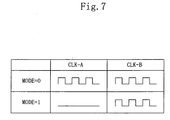
- each of the registers 712, 713 , and 714 picture data are written in the low-order 4-bit storage area and the high-order 4-bit storage area independently of each other by the writing signal CLK-A and the writing signal CLK-B, respectively.
- These two different writing signals: CLK-A and CLK-B are generated in accordance with the value ("0" or "1") of a mode signal (switch signal) set from outside as shown in Fig. 7.
- the writing signal CLK-A occurs only when the mode signal MODE is "0"
- the writing signal CLK-B occurs when the mode signal MODE is "0" or "1". Consequently, when the mode signal MODE is "1", the registers 712-714 can prohibit the writing of data to the low-order 4-bit storage area.
- the low-order 4-bit storage area of each of the registers 712-714 is reset at "0" before they are started.
- the data transfer control circuit 715 fixes the low-order 4 bits at either value (usually at "0") by the mode signal MODE and transfers picture data for the high-order 4 bits on the data bus R to the difference absolute value calculator 710.
- the above-mentioned structure composes a restriction means 30 which controls the wiring of data to the high-order 4 bits and the low-order 4 bits of the registers 712, 713, and 714 separately from each other by the two different writing signals: CLK-A and CLK-B, and also controls the transfer of the high-order 4 bits and the low-order 4 bits of the data transfer control circuit 715 independently of each other by the mode signal MODE.
- each bit string is divided into low-order 4 bits and high-order 4 bits; however, a more minute control can be realized by dividing the bit string into 3 or more.
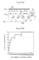
- FIG. 8 (a) shows the entire structure of the motion vector detection apparatus of the present embodiment.
- each block has 256 pixels, and there are cascade-connected 256 PEs 401, a bus R 402 and a bus S 403 for transferring data required for the calculation in each of the PEs 401, a clock line 404 for supplying each PE with an operation clock, and a comparison means 405 for receiving an output of the PE at the final stage.
- the present embodiment is characterized by the internal structure of each PE. All the addition means (the adder 111 shown in Fig. 2) in the PEs 401 have different bit widths from each other: the adder 111 in the PE at a later stage has a larger bit width. In other words, in each PE, the dynamic range of the data to be transferred from the adder 111 to the PE at the next stage is set larger in the PE at a later stage. Since the operations proceed normally unless there is an overflow, it is possible to modify the calculation precision in each PE.
- Fig. 8 (a) nine different PEs which output data with a precision of 8, 9, 10, 11, 12, 13, 14, 15, and 16 bits, respectively, are realized by cascade-connecting them as shown in Fig. 8 (a).
- the number of bits in the adder and the pipeline register (the adder 111 and the pipeline register 114 shown in Fig. 2) can be reduced, as compared with the conventional structure. As a result, both the circuit scale and the power consumption can be reduced.
- the circuit scales of the adder 111 and the pipeline register 114 in each PE can be about 90% of those of their equivalents in the conventional motion vector detection apparatus.
Abstract
Description
- The present invention relates to an improvement of a motion vector detection apparatus which detects motion vectors used for the prediction in motion compensation prediction, which is one of the motion picture compression techniques.
- In transmitting and storing motion picture having a large amount of data, the motion picture compression techniques are inevitable to reduce the large amount of data. The motion picture compression techniques include a compression technique called motion compensation prediction. According to the motion compensation prediction, the level of data redundancy in motion picture is lowered in the direction of the time axis by extracting the displacement between two highly-correlated pictures, so as to compress the amount of data. The displacement between the highly-correlated pictures in the motion compensation is referred to as a motion vector, which is generally detected by a block matching method. The block matching method is briefly described with reference to Fig. 5.
- The block matching method is a method of evaluating the correlation between two pictures in predetermined block units. In Fig. 5, when a motion vector for a block (previous picture) 502 on Picture A 501 is detected, an evaluation value is calculated for each one of a plurality of blocks within a
predetermined search area 504 onPicture B 503. As a result of the calculation, whenblock X 505 shown in Fig. 5 has turned out to have the best evaluation value (the highest correlation), the displacement from the position onPicture B 503 on which the previous picture block 502 is projected toblock X 505 is detected as amotion vector 506. - As the evaluation value indicative of the degree of correlation, a total sum is generally used which is obtained by cumulatively adding the absolute value of the difference between each of the pixels included in a block and a spatially corresponding one of the same number of pixels included in another block. As the evaluation value is smaller, the two blocks have a smaller difference, that is, higher correlation.
- As a conventional motion vector circuit for detecting motion vectors by the above-mentioned block matching method, there is a well-known technique disclosed in Japanese Laid-Open Patent Application No. 7-184210.
- Fig. 1 shows the entire structure of a motion vector detection apparatus, where one block includes 256 pixels, and each pixel has an 8-bit value. The apparatus shown in Fig. 1 includes cascade-connected processor elements (hereinafter PEs) 601 which are as many as the pixels included in one block: 256, a
bus R 602 for transferring the pixel data of one block within thesearch area 504, abus S 603 for transferring the pixel data of the previous picture block 502, aclock line 604 for supplying each of thePEs 601 with an operation clock, and a comparison means 605 for receiving an output of the PE at the final stage and comparing the previous value and the current value of the output. - Fig. 9 show the conventional internal structure of each of the
PEs 601 in the above-mentioned motion vector detection apparatus. The apparatus shown in Fig. 9 includes a differenceabsolute value calculator 610 for calculating the absolute value of the difference of the pixel data to be transferred via thebus R 602 and thebus S 603, anadder 611 for adding an output value of the differenceabsolute value calculator 610 and an output value of the PE at the previous stage together and for outputting the addition results to the PE at the following stage, aregister 612 for storing the pixel data of the previous picture block to be transferred via thebus S 603, apipeline register 613 for pipeline processing the calculations of the differenceabsolute value calculator 610 and theadder 611, and apipeline register 614 for pipeline processing the calculation of theadder 611 of each of thePEs 601. - The operations of the above-mentioned motion vector detection apparatus will be described as follows. The leading pixel data in the previous picture block 502 are stored in the
register 612 and then transferred to the differenceabsolute value calculator 610 in the PE at the first stage (PE0). Also, the leading pixel data of a block (for example, block X 505) within thesearch area 504 are transferred to the differenceabsolute value calculator 610 in the PE at the first stage. The differenceabsolute value calculator 610 calculates the difference absolute value between the received two pixel data, and transfers the calculation results to thepipeline register 613. Theadder 611 receives the difference absolute value from theregister 613 and transfers it to thepipeline register 614 at the following stage, so that the difference absolute value is transferred to the PE at the next stage (PE1). - Then, the second pixel data following the above-mentioned leading pixel data in the previous picture block 502 are transferred to the PE at the second stage (PE1) . Also, the next pixel data in the
block X 505 within thesearch area 504 are transferred to the PE at the second stage. In the PE at the second stage, the difference absolute value between these two pixel data is calculated and the results are stored in thepipeline register 613 in the same manner as in the PE at the first stage. Furthermore, in the PE at the second stage, theadder 611 adds the difference absolute value of the leading pixel data transferred from the PE at the first stage and the difference absolute value of the second pixel data together. The results are stored in thepipeline register 614 and then transferred to the PE at the third stage (PE2). - These operations are repeated hereafter until the total sum of the difference absolute values between all the pixels in the previous picture block 502 and in
block X 505 within thesearch area 504 is obtained in the PE at the final stage (PE255). - These operations are sequentially performed for every block within the
search area 504 although Fig. 5 shows only oneother block Y 507. - The comparison means 605 receives the total sum of the difference absolute values outputted from the PE at the final stage, compares the total sum in the previous block (for example, block X 505) and the total sum in the current block (for example, block Y507), and chooses the smaller of the two total sums. When the total sums of the difference absolute values in all the blocks within the
search area 504 have been calculated and compared, the comparison means 605 obtains the smallest total sum, and outputs, as a motion vector, the displacement between the block having the smallest total sum and the previous picture block 502. - However, the above-mentioned conventional motion vector detection apparatus has drawbacks of demanding huge power consumption because of a large amount of calculation processing needed and of requiring large circuit scales. These drawbacks will be detailed as follows.
- In Fig. 5, Picture A 501 is one of the 30 pictures displayed in one second and its size is 720 pixels×480 lines in the case of standard TV motion picture. Since the standard size of the previous picture block 502 is 16 pixels×16 lines in the motion vector detection used for the motion compensation prediction of the motion picture compression, the number of blocks included within the
search area 504 amounts to 1024. Under these conditions, the number of blocks subject to the block matching amounts to 40, 500 (=720×480×30÷16÷16) per second. A block matching performed for each block requires 262 , 144 (=1,024×16 ×16) times of calculations for the difference absolute values and the total sums. Consequently, the motion vector detection by the block matching method requires as many as 10,616,832,000 (=40,500 × 262,144) times of calculates per second for the difference absolute values and the total sums, which demands huge power consumption. - In order to perform the calculations of the difference absolute values and the addition of these difference absolute values (total sum) with a high precision, it is necessary to make the difference absolute value calculator, the adder, the pipeline register, and other units in each PE have large bit widths. It is also inevitable to provide as many as 256 PEs each including these units, which leads to undesirable expansion of the circuit scales.
- The object of the present invention is to provide a motion vector detection apparatus which has reduced circuit scales and detects motion vectors with low power consumption.
- In order to achieve the object, the present invention has the following features. In the motion compensation prediction, when a motion vector is a displacement between the previous picture block and a block which has sufficiently high correlation with the previous picture block, even if it is not the block having the highest correlation, the level of data redundancy between the pictures can be lowered sufficiently and motion pictures can be compressed at a high compression rate.
- These features bring about the following effects. Firstly, in calculating the evaluation values of a plurality of blocks within a search area, if it is possible to obtain an evaluation value which is not the best, but is as good as the best evaluation value, in other words, if the evaluation value does not need to have a precision (resolution) higher than indicating the level of correlation, the bit width of the adder and other units in each PE can be reduced, and accordingly both the circuit scales and the power consumption can be reduced.
- Secondly, in calculating the total sum of the difference absolute values of pixels with the use of a plurality of PEs, a predetermined setting value (threshold value) can be set as the addition results of the adder in each PE, and when calculated addition results exceed the setting value, that is, when low correlation can be predicted before the total sum is obtained, the useless addition processing of the difference absolute values in the remaining PEs can be halted. As a result, the power consumption can be reduced.
- Thirdly, when a block having sufficiently high correlation with the previous picture block is detected, it is unnecessary to detect a block having higher correlation. Therefore, the calculation of the evaluation values hereafter can be halted, which accordingly decreases the number of calculations, and reduces the consumption power.
- In the conventional motion vector detection apparatus, the
adder 611 on each of PEO-PE255 has a bit width which can express the largest total sum of the difference absolute values obtained in the PE at the final stage. However, theadder 611 adds the difference absolute value calculated in the PE at the present stage to the difference absolute value obtained by theadder 611 in the PE at the previous stage, that is, the total sum of the difference absolute values calculated so far. Therefore, theadder 611 in a PE at a later stage calculates a larger total sum, while theadder 611 in a PE at an earlier stage can manage with a smaller bit width. As a result, it is possible to make theadder 611 in a PE at an earlier stage have a smaller bit width, so as to reduce the circuit scale. - In view of these aspects, the motion vector detection apparatus of the present invention for detecting correlation between a picture consisting of a plurality of pixels and a plurality of blocks each consisting of the same number of pixels as the picture, the plurality of blocks being included within a predetermined search area containing a larger number of pixels than the picture is characterized by comprising: a plurality of PEs which are cascade-connected, each of the PEs calculating a difference absolute value between each of the plurality of pixels included in the picture and a corresponding one of pixels included in every one of the plurality of blocks, and performing cumulative addition of the difference absolute values for every one of the plurality of blocks sequentially; a comparison means for repeatedly comparing cumulative addition values of the difference absolute values of two of the plurality of blocks by subtraction, the cumulative addition values being obtained in the PE at a final stage, and for repeatedly selecting the smaller cumulative addition value; and a restriction means for placing restrictions on calculation of at least one of the comparison means and the plurality of PEs, so as to give a cumulative addition value finally obtained in the comparison means a possibility of becoming a sufficiently small cumulative addition value even if the cumulative addition value is not smallest.
- The above-mentioned motion vector detection apparatus of the present invention is also characterized in that each of the plurality of PEs comprises: a difference absolute value calculation means for calculating the difference between each of the plurality pixels included in the picture and a corresponding one of pixels contained in one of the plurality of blocks, and further calculating the absolute value of the difference, so as to obtain a difference absolute value having a predetermined number of bits; an addition means for adding the difference absolute value obtained by the difference absolute value calculation means and an output of the PE at the previous stage together, and for transferring addition results to the PE at the next stage; and the restriction means being composed of a processing means for truncating or rounding predetermined low-order bits of the difference absolute value obtained by the difference absolute value calculation means, so as to obtain the difference absolute value having high-order bits.
- The above-mentioned motion vector detection apparatus of the present invention is also characterized in that each of the plurality of PEs comprises: a difference absolute value calculation means for calculating the difference between each of the plurality pixels included in the picture and a corresponding one of pixels contained in one of the plurality of blocks, and further calculating the absolute value of the difference, so as to obtain a difference absolute value; an addition means for adding the difference absolute value obtained by the difference absolute value calculation means and an output of the PE at the previous stage together, and for transferring addition results to the PE at the next stage, the addition means being composed of a calculator whose bit width is small; and the restriction means comprising the calculator which composes the addition means and a forced halt means for forcibly halting the cumulative addition of the difference absolute values in the PEs at the following stages when a value calculated by the calculator is larger than the maximum value which can be expressed with the bit width.
- The above-mentioned motion vector detection apparatus of the present invention is also characterized in that the calculator whose bit width is small is composed of a calculator which outputs an overflow signal when a calculated value is larger than the maximum value which can be expressed with the bit width; and the forcible halt means receives the overflow signal from the calculator in the PE at the previous stage, ignores addition results of the addition means, and transfers the overflow signal in each of the PEs at the current stage and the previous stage to the PE at the next stage.
- The above-mentioned motion vector detection apparatus of the present invention is also characterized in that the restriction means compares a setting value with the smaller cumulative addition value selected by the comparison means, and halts the entire operations of the motion vector detection apparatus when the smaller cumulative addition value is smaller than the setting value.
- The above-mentioned motion vector detection apparatus of the present invention is also characterized in that the restriction means comprises: a signal generation means for generating a halt signal when the smaller cumulative addition value is smaller than the setting value; and a control means for halting the supply of a clock signal to each of the PEs and the comparison means when the signal generation means generates the halt signal.
- The above-mentioned motion vector detection apparatus of the present invention is also characterized by further comprising:
- a plurality of registers for storing data, which are provided in each of the plurality of PEs; a data transfer control circuit provided on a data bus for transmitting data of the plurality of pixels composing one block to each of the plurality of PEs; and
- the restriction means dividing each bit string of the plurality of registers and the data transfer control circuit into a plurality of contiguous bit strings and controlling data writing or data transferring of each of the plurality of contiguous bit strings independently.
- The above-mentioned motion vector detection apparatus of the present invention is also characterized in that the restriction means generates a switch signal, so as to halt the supply of a clock signal to predetermined low-order bits of each bit string of the plurality of registers and the data transfer control circuit.
- Another motion vector detection apparatus of the present invention for detecting correlation between a picture consisting of a plurality of pixels and a plurality of blocks each consisting of the same number of pixels as the picture, the plurality of blocks being included within a predetermined search area containing a larger number of pixels than the picture is characterized by comprising: a plurality of PEs which are cascade-connected, each of the plurality of PEs calculating the difference absolute value between each of the plurality of pixels included in the picture and a corresponding one of pixels included in every one of the plurality of blocks, and performing cumulative addition of the difference absolute values for every one of the plurality of blocks sequentially, each of the plurality of PEs comprising: a difference absolute value calculation means for calculating the difference between each of the plurality pixels included in the picture and a corresponding one of pixels contained in one of the plurality of blocks, and further calculating the absolute value of the difference, so as to obtain a difference absolute value; an addition means for adding the difference absolute value obtained by the difference absolute value calculation means and an output of the PE at the previous stage together, and for transferring addition results to the PE at the next stage, and the addition means provided in the PE at the later stage of the plurality of PEs having a larger bit width.
- The above-mentioned motion vector detection apparatus of the present invention is also characterized in that the addition means provided in each of the plurality of PEs has the smallest bit width that does not cause an overflow.
- According to the above-mentioned construction of the present invention, the restriction means puts restrictions on at least one of the calculation in the plurality of PEs and the subtraction processing in the comparison means, so that both the power consumption and the circuit scales can be reduced. In that case, when the cumulative addition value of the difference absolute values finally obtained in the comparison means is a value close to the smallest value, the block having the close value can be used as a block having sufficient correlation in detecting a motion vector so as to lower the level of the data redundancy between pictures sufficiently, and to compress the motion pictures at a high compression rate.
- Since the addition means in each PE has a small bit width, the circuit scale can be small, which accordingly reduces the power consumption.
- When the addition results of the adder exceed the setting value in a PE, or when low correlation is predicted before the total value is finally obtained by continuing the remaining addition, the useless addition processing of the difference absolute values in the remaining PEs is halted, which reduces the power consumption.
- Furthermore, when a block having sufficiently high correlation with the previous picture block is detected, a motion vector is detected based on this block, which makes it unnecessary to detect a block having higher correlation. Consequently, the calculation of the cumulative addition value of the difference absolute values in the remaining blocks is halted, so that the number of calculations is effectively decreased, which reduces the consumption power.
- In addition, the operations of the registers and the low-order bits of the data transfer control circuit are forcibly halted by means of a switching signal. This enable the choice between obtaining a desired precision with all the bits and obtaining a reduced precision with the high-order bits only. The latter processing can reduce the power consumption.
- The bit width of the addition means is set larger in a PE at a later stage. Consequently, the circuit scale can be efficiently reduced, and accordingly, the power consumption is reduced, as compared with the conventional apparatus where the bit width of the addition means at the final stage is adopted in the addition means at all the other stages.
-
- Fig. 1 shows the entire structure of the motion vector detection apparatus of the first embodiment of the present invention.
- Fig. 2 shows the structure of a PE which is a component of the motion vector detection apparatus of the same.
- Fig. 3 shows the structure of a PE of the motion vector detection apparatus of the second embodiment of the present invention.
- Fig. 4 (a) shows the structure of the motion vector detection apparatus of the third embodiment of the present invention, and Fig. 4 (b) shows the internal structure of the comparison means which is a component of the motion vector detection apparatus of the same.
- Fig. 5 shows a diagram which illustrates the block matching method.
- Fig. 6 shows the internal structure of a PE of the motion vector detection apparatus of the fourth embodiment of the present invention.
- Fig. 7 shows the control of the clock signal in the motion vector detection apparatus of the same.
- Fig. 8 (a) shows the entire structure of the motion vector detection apparatus of the fifth embodiment of the present invention, and Fig. 8(b) shows a graph indicating the required number of bits in the adder in each PE.
- Fig. 9 shows the structure of a PE which is a component of a conventional motion vector detection apparatus.
- Each preferred embodiment of the present invention will be described as follows with reference to the attached drawings.
- Figs. 1 and 2 show the motion vector detection apparatus of a first embodiment of the present invention. Since the entire structure of the apparatus shown in Fig. 1 has been described above, the following description will be focused on the internal structure of a PE which is a component of the apparatus with reference to Fig. 2.
- The PE shown in Fig. 2 includes a difference
absolute value calculator 110 for calculating the absolute value of a difference value so as to output an 8-bit difference absolute value, an adder (addition means) 111, aregister 112 which is connected with B terminal of the differenceabsolute value calculator 110 and receives the pixel data of the previous picture block 502 shown in Fig. 5, apipeline register 113 which is disposed on the side of the output of the differenceabsolute value calculator 110, and a pipeline register 114 which is disposed on the side of the output of theadder 111. - In each of the
PEs 601 of the present embodiment, only the high-order 4 bits of an 8-bit difference absolute value are entered to theadder 111 via thepipeline register 113. Therefore, theadder 111 and the twopipeline registers 113 and 114 have 4-bit widths. - Of a difference absolute value outputted from the difference
absolute value calculator 110, the low-order 4 bits are truncated and only the high-order 4 bits are entered to theadder 111, and as a result, a processing means 10 outputs a high-order 4-bit difference calculation value. The processing means 10 composes a restriction means for putting restrictions on the calculation in theadder 111 in a PE. - The operations of the motion vector detection apparatus of the present embodiment will be described as follows. The absolute value of a difference between a pixel in the previous picture block 502 stored in the
register 112 and a pixel inblock X 505 which spatially corresponds to the pixel is calculated in the differenceabsolute value calculator 110, and the high-order 4 bits of the calculated difference absolute value are stored in thepipeline register 113. The difference absolute value stored in thepipeline register 113 and an output of the adder 111 (the sum of the difference absolute values) in the PE at the previous stage are added together by theadder 111 in the PE at the current stage. The addition results are then stored in the pipeline register 114. - In each PE, the low-
order 4 bits of a difference absolute value obtained in the differenceabsolute value calculator 110 are truncated, so that a value obtained as a result of dividing the difference absolute value of the differenceabsolute value calculator 110 by 16 is stored in thepipeline register 113 while the high-order 4-bit difference absolute value is given to theadder 111. Consequently, in the motion vector detection apparatus of the present embodiment, the total sum of the values each obtained as a result of dividing the difference absolute value by 16 is outputted to the PE at the final stage. As a result, the total sum has a lower precision (resolution) than its equivalent in the conventional apparatus, but is sufficiently indicative of the level of correlation, so that a motion vector obtained based on this total sum can be used for the motion compensation prediction to obtain a sufficiently high compression rate. - Another advantage of the present embodiment is that the
adder 111 and the pipeline registers 113 and 114 have as small as a 4-bit width, as compared with the 8-bit width in the conventional apparatus, so that the circuit scale can be small. Furthermore, the power consumption is reduced according to the reduction of the circuit scale. - To be more specific, the circuit scales of the
pipeline register 113, theadder 111, and the pipeline register 114 in the present embodiment can be 50%, 75%, and 75%, respectively, of those of their equivalents in the conventional motion vector detection apparatus. - Although the low-
order 4 bits of an output of the differenceabsolute value calculator 110 are truncated in the present embodiment, it goes without saying that the reduction of the bit width can be also achieved by rounding off to a predetermined bit of the output. - A second embodiment of the present invention will be described based on Fig. 3. The description of the entire structure of the motion vector detection apparatus of the present embodiment will be omitted because the structure is the same as that of the first embodiment shown in Fig. 1.
- Fig. 3 shows the internal structure of one of the PEs. The PE shown in Fig. 3 includes a difference
absolute value calculator 210, anadder 211, aregister 212, andpipeline registers conventional adder 611 shown in Fig. 9 has a 16-bit width, theadder 211 of the present embodiment is composed of a calculator with a smaller bit width, such as a 10-bit width. - The
adder 211 outputs anoverflow signal 215 when a calculated value is larger than the maximum value (threshold value) which can be expressed in the 10-bit width. An ORcircuit 216 receives theoverflow signal 215 from theadder 211 and an output signal of the PE at the previous stage (not shown) via thesignal path 216a, and ORs these signals. The output of theOR circuit 216 is transferred to the OR circuit in the PE at the next stage (not shown) via thepipeline register 217. A transition prohibition means 218 receives theoverflow signal 215 from theadder 211 so as to prohibit the transition of the data stored in thepipeline register 214 which is at the stage following theadder 211. - When the
adder 211 in a PE outputs a value larger than the above-mentioned threshold value, the transition prohibition means 218 in the PE at the next stage prohibits the transition of the data stored in thepipeline register 214 of the PE at the current stage, based on theoverflow signal 215. As a result, a forced halt means 20 is formed which forcibly halts the cumulative addition of the difference absolute values in the PE at and after the next stage by ignoring the addition results of theadder 211 at the current stage, and which transfers overflow signals from the PEs at the current and previous stages to the PE at the following stage via theOR circuit 216 and thepipeline register 217. - The following is a description of the operations of the motion vector detection apparatus of the present embodiment. The
adder 211 outputs theoverflow signal 215 when its calculation results are equal to or larger than the threshold value, which is the maximum value that can be expressed in 10 bits. The ORcircuit 216 ORs theoverflow signal 215 from theadder 211 and theoverflow signal 215 from the PE at the previous stage, and transfers the results to the PE at the next stage via thepipeline register 217. In each PE, when theoverflow signal 215 is transferred from the PE at the previous stage, the transition prohibition means 218 prohibits the transition of the data stored in thepipeline register 214 by halting the supply of a clock signal or by another method. As a result, when the calculated value is equal to or larger than the threshold value, the calculation of the total sum hereafter is halted, which realizes the reduction of the power consumption. In the next time, the calculation of the total sum of the difference absolute values is performed with regard to each of the remaining blocks (for example, blockY 507 shown in Fig. 5) within thesearch area 504. Then, the displacement between the block having the smallest total sum and the previous picture block is detected as a motion vector. - When the total sum calculation is halted based on the
overflow signal 215, the evaluation value outputted from the PE at the final stage becomes indefinite value. However, this indefinite evaluation value can be prevented from being mistakenly regarded as the smallest evaluation value, by making the comparison means 605 receive theoverflow signal 215 and making the indefinite value be excluded from the comparison target. - When the
adder 211 has a 10-bit width in the present embodiment, the circuit scales of theadder 211 and thepipeline register 214 can be 62.5% of those of their equivalents in the conventional motion vector detection apparatus. - The data transition in the
pipeline register 214 in the PE at the current stage is prohibited by theoverflow signal 215 in the PE at the previous stage in the present embodiment. However, by prohibiting thepipeline register 213 in the PE at the current stage from performing data transition by means of theoverflow signal 215 in the PE two stages before, it becomes possible to prohibit theadder 211 from performing useless calculation in the PEs after the current stage and also to prohibit thepipeline register 213 from performing data transition. Furthermore, by prohibiting the transition of a signal entered to A terminal of the differenceabsolute value calculator 210 at the current stage by means of theoverflow signal 215 in the PE three stages before, it becomes possible to prohibit the differenceabsolute value calculator 210 from performing useless calculation in the PEs after the current stage. As a result, the power consumption can be further reduced. - A third embodiment of the present invention will be described based on Figs. 4 (a) and 4 (b).
- Fig. 4 (a) shows the entire structure of the motion vector detection apparatus of the present embodiment. This structure shows a case where each block has 256 pixels, and there are cascade-connected
PEs 301 whose number is the same as that of the pixels. Abus R 302 and abus S 303 transfer the pixel data required for the calculation in each of thePEs 301, and aclock line 304 supplies each PE with an operation clock. A comparison means 305 enters an output value of the PE at the final stage. - The present embodiment is characterized by the structures of the comparison means 305 and the
clock line 304. Fig. 4 (b) shows the internal structure of the comparison means 305. In the comparison means 305, acomparator 310 compares output value A of the PE at the final stage and holding value B stored in theregister 311 by subtraction, and when the subtraction results (A -B) is a negative value, rewrites the contents stored in theregister 311 to output value A of the PE at the final stage. The data writing of theregister 311 is controlled by thecontrol circuit 312. Thecontrol circuit 312 generates a write control signal, based on MSB (Most Significant Bit) of an output of thecomparator 310 and on a clock signal supplied from theclock line 304, and outputs the control signal to theregister 311. - The comparison means 305 further includes a
subtracter 313 and a settingvalue register 314 which stores a predetermined setting value as the cumulative addition value of the difference absolute values obtained in the PE at the final stage. Thesubtracter 313 subtracts the smaller cumulative addition value which is actually obtained in the PE at the final stage and which is stored in theregister 311, from the setting value stored in the settingvalue register 314. When the actually obtained cumulative addition value is smaller than the setting value, thesubtracter 313 outputs the MSB of the subtraction results as a clock halt signal (halt signal). Thesubtracter 313 functions as a signal generation circuit. - In Fig. 4 (a), a control circuit (control means) 320 is provided on the
clock line 304. Thecontrol circuit 320 receives the clock halt signal from thesubtracter 313 and halts the supply of the clock signal to theclock line 304. Consequently, when the clock halt signal is generated, each of thePEs 301, and thecomparator 310 and theregister 311 of the comparison means 305 do not receive a clock signal and halts their operations. Unlike in the present embodiment, it is possible to adopt a construction where the transfer of pixel data to each PE is halted by the halt signal of thesubtracter 313. Thesubtracter 313 and thecontrol circuit 320 compose a restriction means which halts the entire operations of the motion vector detection apparatus when the value stored in the register 311 (that is, the smaller cumulative addition value actually obtained in the PE at the final stage) is smaller than the setting value. - Consequently, according to the present embodiment, when the cumulative addition value actually obtained in the PE at the final stage is smaller than the setting value, the following operations of the entire apparatus are halted, and a motion vector can be detected by using the block having the cumulative addition value smaller than the setting value as the block having sufficiently high correlation with the previous picture block. Thus, in the present embodiment, when a block having sufficient correlation with the previous picture block is obtained, the calculation of the cumulative addition value of the difference absolute values in the remaining blocks within the
search area 504 can be halted. As a result, the power consumption can be reduced, as compared with the conventional apparatus which always has to calculate the cumulative addition value of the difference absolute values in all the blocks within thesearch area 504. - A fourth embodiment of the present invention will be described based on Figs. 6 and 7.
- Fig. 6 shows the structure of a PE in the motion vector detection apparatus of the present embodiment. The structure includes a difference
absolute value calculator 710, anadder 711, aregister 712 which is disposed at the previous stage of the differenceabsolute value calculator 710 and which receives the pixel data of the previous picture block shown in Fig. 5, a pipeline register (register) 713 which is disposed at the stage following the differenceabsolute value calculator 710, a pipeline register (register) 714 which is disposed at the stage following theadder 711, and a datatransfer control circuit 715 which receives the pixel data of theblocks search area 504 shown in Fig. 5 via the data bus R. - In each of the
registers - The data
transfer control circuit 715 fixes the low-order 4 bits at either value (usually at "0") by the mode signal MODE and transfers picture data for the high-order 4 bits on the data bus R to the differenceabsolute value calculator 710. - The above-mentioned structure composes a restriction means 30 which controls the wiring of data to the high-
order 4 bits and the low-order 4 bits of theregisters order 4 bits and the low-order 4 bits of the datatransfer control circuit 715 independently of each other by the mode signal MODE. - In the motion detection which deals with natural pictures such as the MPEG standard, even if the low-order bits are ignored, almost the same level of a precision as the case where all the bits are used can be obtained, so that the picture quality is hardly affected. When the motion detection dealing with natural pictures is performed in the present embodiment, the operation of the low-
order 4 bits of each of the registers 712-714 and the datatransfer control circuit 715 can be halted, so as to reduce the power consumption without losing satisfactory picture quality. - In each of the registers 712-714 and the data
transfer control circuit 715, each bit string is divided into low-order 4 bits and high-order 4 bits; however, a more minute control can be realized by dividing the bit string into 3 or more. - Finally, a fifth embodiment of the present invention will be described based on Figs. 8 (a) and 8 (b). Fig. 8 (a) shows the entire structure of the motion vector detection apparatus of the present embodiment. In the structure, each block has 256 pixels, and there are cascade-connected 256
PEs 401, abus R 402 and abus S 403 for transferring data required for the calculation in each of thePEs 401, aclock line 404 for supplying each PE with an operation clock, and a comparison means 405 for receiving an output of the PE at the final stage. - The present embodiment is characterized by the internal structure of each PE. All the addition means (the
adder 111 shown in Fig. 2) in thePEs 401 have different bit widths from each other: theadder 111 in the PE at a later stage has a larger bit width. In other words, in each PE, the dynamic range of the data to be transferred from theadder 111 to the PE at the next stage is set larger in the PE at a later stage. Since the operations proceed normally unless there is an overflow, it is possible to modify the calculation precision in each PE. The dynamic range D of theadder 111 at each stage (i) when the pixel data have 8 bits can be expressed by the following equation:
- Consequently, the smallest bit width of the data to be transferred to the PE in the following stage is an integer to which the value D is raised. The results are shown in Fig. 8 (b).
- In the present embodiment, nine different PEs which output data with a precision of 8, 9, 10, 11, 12, 13, 14, 15, and 16 bits, respectively, are realized by cascade-connecting them as shown in Fig. 8 (a).
- According to the above-mentioned structure, the number of bits in the adder and the pipeline register (the
adder 111 and the pipeline register 114 shown in Fig. 2) can be reduced, as compared with the conventional structure. As a result, both the circuit scale and the power consumption can be reduced. - In the present embodiment, as apparent from Fig. 8 (b), the circuit scales of the
adder 111 and the pipeline register 114 in each PE can be about 90% of those of their equivalents in the conventional motion vector detection apparatus. - Each of the above-mentioned embodiments can obtain the effects of reducing the circuit scales and the power consumption independently, so that any of the embodiments can be combined to enhance the effects.
Claims (7)
- A motion vector detection apparatus for detecting a correlation between a picture (502) and a plurality of blocks (505-507), the picture (502) and the plurality of blocks (505-507) consisting of the same number of pixels, the plurality of blocks (505-507) being included within a predetermined search area (504) containing a larger number of pixels than said picture (502), said motion vector detection apparatus comprising a plurality of processor elements (601) for calculating absolute difference values between pixels of said picture (502) and corresponding pixels of said plurality of blocks (505-507)
characterized in that
the plurality of processor elements (601) is cascade-connected wherein the number of processor elements (601) corresponds to the number of pixels included in said picture (502), wherein each processor element (601) calculates absolute difference values between a pixel of said picture (502) and corresponding pixels included in the plurality of blocks (505-507) and accumulates a calculated absolute difference value and an accumulation result received from a processing element (601) of the previous stage within the cascade-connection of processor element (601),
wherein each processor element (601) reduces the number of bits of a calculated absolute difference value. - A motion vector detecting apparatus according to claim 1, wherein each processor element (601) being further adapted to truncate or round predetermined low-order bits of a calculated absolute difference value so as to obtain an absolute difference value having high-order bits.
- A motion vector detection apparatus for detecting a correlation between a picture (502) and a plurality of blocks (505-507), the picture (502) and the plurality of blocks (505-507) consisting of the same number of pixels, the plurality of blocks (505-507) being included within a predetermined search area (504) containing a larger number of pixels than said picture (502), said motion vector detection apparatus comprising a plurality of processor elements (601) for calculating absolute difference values between pixels of said picture (502) and corresponding pixels of said plurality of blocks (505-507) and comparison means (605) for detecting a minimum of accumulated absolute difference values accumulated for each of the plurality of blocks (505-507), respectively,
characterized in that
the plurality of processor elements (601) is cascade-connected wherein the number of processor elements (601) corresponds to the number of pixels included in said picture (502), wherein each processor element (601) calculates absolute difference values between a pixel of said picture (502) and corresponding pixels included in the plurality of blocks (505-507) and accumulates a calculated absolute difference value and an accumulation result received from a processing element (601) of the previous stage within the cascade-connection of processor element (601),
wherein said comparison means (605) being adapted to terminate the minimum detection when a currently detected minimum being smaller than a predetermined reference value. - A motion vector detection apparatus according to claim 3, wherein said comparison means (605) comprises
a signal generation means for generating a halt signal when a current minimum being smaller than the reference value, and
a control means for halting supply of a clock signal for each of said plurality of processor elements (301) and said comparison means (305) when said signal generation means generates the halt signal. - A motion vector detection apparatus for detecting a correlation between a picture (502) and a plurality of blocks (505-507), the picture (502) and the plurality of blocks (505-507) consisting of the same number of pixels, the plurality of blocks (505-507) being included within a predetermined search area (504) containing a larger number of pixels than said picture (502), said motion vector detection apparatus comprising a plurality of processor elements (601) for calculating absolute difference values between pixels of said picture (502) and corresponding pixels of said plurality of blocks (505-507)
characterized in that
the plurality of processor elements (601) is cascade-connected wherein the number of processor elements (601) corresponds to the number of pixels included in said picture (502), wherein each processor element (601) calculates absolute difference values between a pixel of said picture (502) and corresponding pixels included in the plurality of blocks (505-507) and accumulates a calculated absolute difference value and an accumulation result received from a processing element (601) of the previous stage within the cascade-connection of processor element (601),
wherein each processor element (601) being adapted to control the number of bits of each data value to be processed. - A motion vector detection apparatus according to claim 5, wherein each processor element (601) further comprises:plurality of registers (712-714) for storing data,a data transfer control circuit (715) provided on a data bus (716) for transmitting data of the plurality of pixels of one block to each of said plurality of processor elements (601), andwherein each bit string of said plurality of registers (712-714) and said data transfer control circuit (715) being divided into a plurality of contiguous bits strings and the writing and transferring of data of each of the plurality of contiguous bit strings being controlled independently.
- A motion vector detection apparatus according to claim 6, wherein a switch signal being generated so as to halt supply of a clock signal to predetermine low-order bits of each bit string of said plurality of registers (712-714) and said data transfer control circuit (715).
Applications Claiming Priority (2)
| Application Number | Priority Date | Filing Date | Title |
|---|---|---|---|
| JP202897 | 1997-01-09 | ||
| EP98100223A EP0854439B1 (en) | 1997-01-09 | 1998-01-08 | Motion vector detection apparatus |
Related Parent Applications (1)
| Application Number | Title | Priority Date | Filing Date |
|---|---|---|---|
| EP98100223A Division EP0854439B1 (en) | 1997-01-09 | 1998-01-08 | Motion vector detection apparatus |
Publications (2)
| Publication Number | Publication Date |
|---|---|
| EP1622084A2 true EP1622084A2 (en) | 2006-02-01 |
| EP1622084A3 EP1622084A3 (en) | 2006-04-05 |
Family
ID=11517890
Family Applications (3)
| Application Number | Title | Priority Date | Filing Date |
|---|---|---|---|
| EP05024129A Withdrawn EP1622084A3 (en) | 1997-01-09 | 1998-01-08 | Motion vector detection apparatus |
| EP00121600A Expired - Lifetime EP1074941B1 (en) | 1997-01-09 | 1998-01-08 | Motion vector detection apparatus |
| EP98100223A Expired - Lifetime EP0854439B1 (en) | 1997-01-09 | 1998-01-08 | Motion vector detection apparatus |
Family Applications After (2)
| Application Number | Title | Priority Date | Filing Date |
|---|---|---|---|
| EP00121600A Expired - Lifetime EP1074941B1 (en) | 1997-01-09 | 1998-01-08 | Motion vector detection apparatus |
| EP98100223A Expired - Lifetime EP0854439B1 (en) | 1997-01-09 | 1998-01-08 | Motion vector detection apparatus |
Country Status (6)
| Country | Link |
|---|---|
| US (1) | US6154492A (en) |
| EP (3) | EP1622084A3 (en) |
| KR (1) | KR100766198B1 (en) |
| CN (1) | CN1141661C (en) |
| DE (2) | DE69832217T2 (en) |
| TW (1) | TW361051B (en) |
Families Citing this family (39)
| Publication number | Priority date | Publication date | Assignee | Title |
|---|---|---|---|---|
| US6567469B1 (en) * | 2000-03-23 | 2003-05-20 | Koninklijke Philips Electronics N.V. | Motion estimation algorithm suitable for H.261 videoconferencing applications |
| US6907080B1 (en) * | 2000-06-07 | 2005-06-14 | Intel Corporation | Adaptive early exit techniques in image correlation |
| US6700996B1 (en) | 2000-06-07 | 2004-03-02 | Intel Corporation | Adaptive early exit techniques in image correlation |
| US6654502B1 (en) | 2000-06-07 | 2003-11-25 | Intel Corporation | Adaptive early exit techniques in image correlation |
| EP1241892A1 (en) * | 2001-03-06 | 2002-09-18 | Siemens Aktiengesellschaft | Hardware accelerator for video signal processing system |
| US7249242B2 (en) * | 2002-10-28 | 2007-07-24 | Nvidia Corporation | Input pipeline registers for a node in an adaptive computing engine |
| US7653710B2 (en) | 2002-06-25 | 2010-01-26 | Qst Holdings, Llc. | Hardware task manager |
| US6836839B2 (en) | 2001-03-22 | 2004-12-28 | Quicksilver Technology, Inc. | Adaptive integrated circuitry with heterogeneous and reconfigurable matrices of diverse and adaptive computational units having fixed, application specific computational elements |
| US7962716B2 (en) | 2001-03-22 | 2011-06-14 | Qst Holdings, Inc. | Adaptive integrated circuitry with heterogeneous and reconfigurable matrices of diverse and adaptive computational units having fixed, application specific computational elements |
| US6577678B2 (en) | 2001-05-08 | 2003-06-10 | Quicksilver Technology | Method and system for reconfigurable channel coding |
| FI110744B (en) * | 2001-09-06 | 2003-03-14 | Nokia Corp | Method of Performing Motion Estimation in Video Coding, Video Coding System and Video Coding Device |
| US8412915B2 (en) | 2001-11-30 | 2013-04-02 | Altera Corporation | Apparatus, system and method for configuration of adaptive integrated circuitry having heterogeneous computational elements |
| US7039246B2 (en) * | 2002-05-03 | 2006-05-02 | Qualcomm Incorporated | Video encoding techniques |
| US7328414B1 (en) | 2003-05-13 | 2008-02-05 | Qst Holdings, Llc | Method and system for creating and programming an adaptive computing engine |
| US7660984B1 (en) | 2003-05-13 | 2010-02-09 | Quicksilver Technology | Method and system for achieving individualized protected space in an operating system |
| US7940844B2 (en) * | 2002-06-18 | 2011-05-10 | Qualcomm Incorporated | Video encoding and decoding techniques |
| US8108656B2 (en) | 2002-08-29 | 2012-01-31 | Qst Holdings, Llc | Task definition for specifying resource requirements |
| US20040062308A1 (en) * | 2002-09-27 | 2004-04-01 | Kamosa Gregg Mark | System and method for accelerating video data processing |
| US20060126718A1 (en) * | 2002-10-01 | 2006-06-15 | Avocent Corporation | Video compression encoder |
| US7321623B2 (en) | 2002-10-01 | 2008-01-22 | Avocent Corporation | Video compression system |
| US6933982B2 (en) * | 2002-10-07 | 2005-08-23 | Koninklijke Philips Electronics N.V. | Method and apparatus for fast robust estimation of image noise in a video processing system |
| US7225301B2 (en) | 2002-11-22 | 2007-05-29 | Quicksilver Technologies | External memory controller node |
| US9560371B2 (en) * | 2003-07-30 | 2017-01-31 | Avocent Corporation | Video compression system |
| JP4015084B2 (en) * | 2003-08-20 | 2007-11-28 | 株式会社東芝 | Motion vector detection apparatus and motion vector detection method |
| US10316616B2 (en) | 2004-05-28 | 2019-06-11 | Schlumberger Technology Corporation | Dissolvable bridge plug |
| US7457461B2 (en) | 2004-06-25 | 2008-11-25 | Avocent Corporation | Video compression noise immunity |
| US20070150697A1 (en) * | 2005-05-10 | 2007-06-28 | Telairity Semiconductor, Inc. | Vector processor with multi-pipe vector block matching |
| US20060259737A1 (en) * | 2005-05-10 | 2006-11-16 | Telairity Semiconductor, Inc. | Vector processor with special purpose registers and high speed memory access |
| JP4879558B2 (en) * | 2005-11-02 | 2012-02-22 | パナソニック株式会社 | Motion vector detection device |
| US8770261B2 (en) | 2006-02-09 | 2014-07-08 | Schlumberger Technology Corporation | Methods of manufacturing degradable alloys and products made from degradable alloys |
| US7555570B2 (en) | 2006-02-17 | 2009-06-30 | Avocent Huntsville Corporation | Device and method for configuring a target device |
| US8718147B2 (en) | 2006-02-17 | 2014-05-06 | Avocent Huntsville Corporation | Video compression algorithm |
| GB2436656A (en) * | 2006-03-31 | 2007-10-03 | Tandberg Television Asa | Computing a sliding sum of absolute differences for video signal compression |
| MY149291A (en) * | 2006-04-28 | 2013-08-30 | Avocent Corp | Dvc delta commands |
| US8290044B2 (en) * | 2006-05-10 | 2012-10-16 | Qualcomm Incorporation | Instruction for producing two independent sums of absolute differences |
| US20080182021A1 (en) * | 2007-01-31 | 2008-07-31 | Simka Harsono S | Continuous ultra-thin copper film formed using a low thermal budget |
| JP5990466B2 (en) | 2010-01-21 | 2016-09-14 | スビラル・インコーポレーテッド | Method and apparatus for a general purpose multi-core system for implementing stream-based operations |
| US10108581B1 (en) * | 2017-04-03 | 2018-10-23 | Google Llc | Vector reduction processor |
| CN108989638B (en) * | 2018-08-01 | 2021-03-05 | Oppo(重庆)智能科技有限公司 | Imaging apparatus, control method thereof, electronic apparatus, and computer-readable storage medium |
Citations (1)
| Publication number | Priority date | Publication date | Assignee | Title |
|---|---|---|---|---|
| JPH07184210A (en) | 1993-12-24 | 1995-07-21 | Matsushita Electric Ind Co Ltd | Motion vector detection circuit |
Family Cites Families (19)
| Publication number | Priority date | Publication date | Assignee | Title |
|---|---|---|---|---|
| US4622632A (en) * | 1982-08-18 | 1986-11-11 | Board Of Regents, University Of Washington | Data processing system having a pyramidal array of processors |
| US4860248A (en) * | 1985-04-30 | 1989-08-22 | Ibm Corporation | Pixel slice processor with frame buffers grouped according to pixel bit width |
| JP3004685B2 (en) * | 1990-07-02 | 2000-01-31 | 沖電気工業株式会社 | Motion vector detection circuit |
| JP3228927B2 (en) * | 1990-09-20 | 2001-11-12 | 沖電気工業株式会社 | Processor element, processing unit, processor, and arithmetic processing method thereof |
| US5477278A (en) * | 1991-12-24 | 1995-12-19 | Sharp Kabushiki Kaisha | Apparatus for detecting motion of moving picture |
| JPH06189291A (en) * | 1992-12-21 | 1994-07-08 | Sharp Corp | Device for detecting motion of picture |
| KR950014343B1 (en) * | 1993-05-20 | 1995-11-24 | 한국방송공사 | Method of and apparatus for motion estimation of video data |
| JP2636674B2 (en) * | 1993-05-25 | 1997-07-30 | 日本電気株式会社 | Video motion vector detection device |
| EP0639926A1 (en) * | 1993-08-16 | 1995-02-22 | THOMSON multimedia | Method and apparatus for motion vector estimation using block matching |
| JPH07162864A (en) * | 1993-12-08 | 1995-06-23 | Ricoh Co Ltd | Motion vector detecting method |
| JP3606597B2 (en) * | 1994-01-21 | 2005-01-05 | ソニー株式会社 | Motion vector detection device |
| JP3089165B2 (en) * | 1994-11-10 | 2000-09-18 | 株式会社グラフィックス・コミュニケーション・ラボラトリーズ | Motion vector search device |
| US5696836A (en) * | 1995-03-17 | 1997-12-09 | Lsi Logic Corporation | Motion estimation processor architecture for full search block matching |
| US5712799A (en) * | 1995-04-04 | 1998-01-27 | Chromatic Research, Inc. | Method and structure for performing motion estimation using reduced precision pixel intensity values |
| JPH0965339A (en) * | 1995-08-18 | 1997-03-07 | Mitsubishi Electric Corp | Image block motion detector |
| KR970032164A (en) * | 1995-11-30 | 1997-06-26 | 배순훈 | Motion estimator |
| KR0178302B1 (en) * | 1995-12-08 | 1999-05-01 | 김은영 | Motion estimation processor based on the bidirectional parallel pipe line structure |
| US5719642A (en) * | 1996-05-07 | 1998-02-17 | National Science Council Of R.O.C. | Full-search block matching motion estimation processor |
| GB2320388B (en) * | 1996-11-29 | 1999-03-31 | Sony Corp | Image processing apparatus |
-
1998
- 1998-01-02 TW TW087100058A patent/TW361051B/en not_active IP Right Cessation
- 1998-01-08 US US09/004,414 patent/US6154492A/en not_active Expired - Fee Related
- 1998-01-08 EP EP05024129A patent/EP1622084A3/en not_active Withdrawn
- 1998-01-08 DE DE69832217T patent/DE69832217T2/en not_active Expired - Lifetime
- 1998-01-08 CN CNB981000134A patent/CN1141661C/en not_active Expired - Fee Related
- 1998-01-08 DE DE69813629T patent/DE69813629T2/en not_active Expired - Lifetime
- 1998-01-08 EP EP00121600A patent/EP1074941B1/en not_active Expired - Lifetime
- 1998-01-08 EP EP98100223A patent/EP0854439B1/en not_active Expired - Lifetime
- 1998-01-09 KR KR1019980000403A patent/KR100766198B1/en not_active IP Right Cessation
Patent Citations (1)
| Publication number | Priority date | Publication date | Assignee | Title |
|---|---|---|---|---|
| JPH07184210A (en) | 1993-12-24 | 1995-07-21 | Matsushita Electric Ind Co Ltd | Motion vector detection circuit |
Also Published As
| Publication number | Publication date |
|---|---|
| US6154492A (en) | 2000-11-28 |
| TW361051B (en) | 1999-06-11 |
| KR19980070438A (en) | 1998-10-26 |
| EP0854439B1 (en) | 2005-11-09 |
| DE69832217T2 (en) | 2006-06-01 |
| EP1074941A3 (en) | 2001-02-14 |
| EP1074941A2 (en) | 2001-02-07 |
| KR100766198B1 (en) | 2007-12-14 |
| EP0854439A2 (en) | 1998-07-22 |
| DE69813629T2 (en) | 2004-02-05 |
| EP1074941B1 (en) | 2003-04-16 |
| DE69832217D1 (en) | 2005-12-15 |
| DE69813629D1 (en) | 2003-05-22 |
| EP0854439A3 (en) | 1999-11-03 |
| EP1622084A3 (en) | 2006-04-05 |
| CN1195824A (en) | 1998-10-14 |
| CN1141661C (en) | 2004-03-10 |
Similar Documents
| Publication | Publication Date | Title |
|---|---|---|
| EP1622084A2 (en) | Motion vector detection apparatus | |
| US5838828A (en) | Method and apparatus for motion estimation in a video signal | |
| EP0447068B1 (en) | Motion image data compression system | |
| US6661469B1 (en) | False contour correcting apparatus and method | |
| US6456660B1 (en) | Device and method of detecting motion vectors | |
| US5696836A (en) | Motion estimation processor architecture for full search block matching | |
| US5793655A (en) | Sum of the absolute values generator | |
| EP0387849B1 (en) | Correlation computing device | |
| KR100303107B1 (en) | Motion vector detection apparatus and method | |
| US5587808A (en) | Image processing apparatus for identifying character, photo and dot images in image area | |
| KR100416444B1 (en) | Motion vector selection method and image processing device performing this method | |
| US5208770A (en) | Accumulation circuit having a round-off function | |
| US6169766B1 (en) | Method and apparatus for detecting motion vector and image coding apparatus | |
| EP0819284B1 (en) | Method and structure for performing motion estimation using reduced precision pixel intensity values | |
| US4994911A (en) | Image information signal transmitting system with selective transmission of input data or extracted data | |
| US5581309A (en) | Motion vector detecting circuit | |
| JP2007228156A (en) | Movement detection processing apparatus and method thereof | |
| US20030067986A1 (en) | Circuit and method for full search block matching | |
| JP2954120B2 (en) | Motion vector detection device | |
| US6477557B1 (en) | Division circuit not requiring taking complements of divisor, dividend and remainder | |
| US7272184B2 (en) | Programmable system for motion vector generation | |
| US7800624B2 (en) | Memory device signal processing apparatus image signal processing apparatus and methods of the same | |
| KR19980077470A (en) | The motion vector detection device | |
| JP2004096709A (en) | Image processing apparatus and image processing method | |
| US6112205A (en) | Data processing equipment and method for classifying data into classes in accordance with a plurality of thresholds for quantizing data |
Legal Events
| Date | Code | Title | Description |
|---|---|---|---|
| PUAI | Public reference made under article 153(3) epc to a published international application that has entered the european phase |
Free format text: ORIGINAL CODE: 0009012 |
|
| 17P | Request for examination filed |
Effective date: 20051104 |
|
| AC | Divisional application: reference to earlier application |
Ref document number: 0854439 Country of ref document: EP Kind code of ref document: P |
|
| AK | Designated contracting states |
Kind code of ref document: A2 Designated state(s): AT BE CH DE DK ES FI FR GB GR IE IT LI LU MC NL PT SE |
|
| AX | Request for extension of the european patent |
Extension state: AL |
|
| PUAL | Search report despatched |
Free format text: ORIGINAL CODE: 0009013 |
|
| AK | Designated contracting states |
Kind code of ref document: A3 Designated state(s): AT BE CH DE DK ES FI FR GB GR IE IT LI LU MC NL PT SE |
|
| AX | Request for extension of the european patent |
Extension state: AL |
|
| RIN1 | Information on inventor provided before grant (corrected) |
Inventor name: AOKI, KATSUJIC/O MATSUSHITA ELEC IND CO LTD. Inventor name: ARAKI, TOSHIYUKI |
|
| 17Q | First examination report despatched |
Effective date: 20060825 |
|
| AKX | Designation fees paid |
Designated state(s): DE FR GB NL |
|
| STAA | Information on the status of an ep patent application or granted ep patent |
Free format text: STATUS: THE APPLICATION IS DEEMED TO BE WITHDRAWN |
|
| 18D | Application deemed to be withdrawn |
Effective date: 20070106 |