EP1626425A1 - Circuit interrupter including linear actuator and manual pivot member - Google Patents
Circuit interrupter including linear actuator and manual pivot member Download PDFInfo
- Publication number
- EP1626425A1 EP1626425A1 EP05017779A EP05017779A EP1626425A1 EP 1626425 A1 EP1626425 A1 EP 1626425A1 EP 05017779 A EP05017779 A EP 05017779A EP 05017779 A EP05017779 A EP 05017779A EP 1626425 A1 EP1626425 A1 EP 1626425A1
- Authority
- EP
- European Patent Office
- Prior art keywords
- close
- open
- arm
- link
- operating mechanism
- Prior art date
- Legal status (The legal status is an assumption and is not a legal conclusion. Google has not performed a legal analysis and makes no representation as to the accuracy of the status listed.)
- Withdrawn
Links
Images


Classifications
-
- H—ELECTRICITY
- H01—ELECTRIC ELEMENTS
- H01H—ELECTRIC SWITCHES; RELAYS; SELECTORS; EMERGENCY PROTECTIVE DEVICES
- H01H33/00—High-tension or heavy-current switches with arc-extinguishing or arc-preventing means
- H01H33/60—Switches wherein the means for extinguishing or preventing the arc do not include separate means for obtaining or increasing flow of arc-extinguishing fluid
- H01H33/66—Vacuum switches
- H01H33/666—Operating arrangements
- H01H33/6662—Operating arrangements using bistable electromagnetic actuators, e.g. linear polarised electromagnetic actuators
-
- H—ELECTRICITY
- H01—ELECTRIC ELEMENTS
- H01H—ELECTRIC SWITCHES; RELAYS; SELECTORS; EMERGENCY PROTECTIVE DEVICES
- H01H33/00—High-tension or heavy-current switches with arc-extinguishing or arc-preventing means
- H01H33/02—Details
- H01H33/022—Details particular to three-phase circuit breakers
Definitions
- This invention pertains generally to circuit interrupters and, more particularly, to such circuit interrupters employing one or more pole mechanisms.
- Circuit interrupters provide protection for electrical systems from electrical fault conditions such as, for example, current overloads, short circuits and abnormal level voltage conditions.
- circuit interrupters include a spring powered operating mechanism which opens electrical contacts to interrupt the current through the conductors of an electrical system in response to abnormal conditions.
- Circuit interrupters such as, for example, power circuit breakers for systems operating above about 1,000 volts typically utilize vacuum interrupters as the switching devices.
- each vacuum interrupter is housed in a separate pod molded of an electrically insulative material, such as a polyglass. These molded pods, in turn, are bolted to a metal box containing the operating mechanism. The metal box is grounded to isolate the operating mechanism from the line voltage of the power circuit. Manual controls for the operating mechanism are accessible at the front face of the metal box. See, for example, U.S. Patent No. 6,373,358.
- Vacuum circuit interrupter apparatus include separable main contacts disposed within an insulating housing. Generally, one of the contacts is fixed relative to both the housing and to an external electrical conductor which is interconnected with the circuit to be controlled by the circuit interrupter. The other contact is moveable.
- the moveable contact assembly usually comprises a stem of circular cross-section having the contact at one end enclosed within a vacuum chamber and a driving mechanism at the other end which is external to the vacuum chamber.
- An operating rod assembly comprising a push rod, which is fastened to the end of the stem opposite the moveable contact, and a driving mechanism provide the motive force to move the moveable contact into or out of engagement with the fixed contact.
- the operating rod assembly is operatively connected to a latchable operating mechanism which is responsive to an abnormal current condition.
- the latchable operating mechanism becomes unlatched which causes the operating rod to move to the open position.
- the motion of the operating rod causes a contact bell crank to rotate and this controls motion of the moveable contact.
- Compression springs are provided in connection with the operating rod assembly in order to be able to separate the moveable contact from the fixed contact and to assure the necessary force so that the contacts will not accidentally open under inappropriate conditions.
- an adequate force is needed to open the contacts with sufficient speed. If the contacts do not open quickly, then there is a risk of the contacts welding together and failure to interrupt the current.
- Vacuum interrupters are typically used, for instance, to reliably interrupt medium voltage alternating current (AC) currents and, also, high voltage AC currents of several thousands of amperes or more.
- AC medium voltage alternating current
- one vacuum interrupter is provided for each phase of a multi-phase circuit and the vacuum interrupters for the several phases are actuated simultaneously by a common latchable operating mechanism.
- United States Patent Application Publication No. 2004/0118815 discloses an electrical interrupter apparatus including an interruption device, an insulation member, a base, a driving system and a linkage mechanism.
- a plurality of the electrical interrupter apparatuses may be incorporated into a circuit breaker, such as a 72.5 kV outdoor circuit breaker or other circuit breaker.
- the driving system includes a drive unit and a return spring.
- the drive unit is mounted within the base and can be any of a wide variety of mechanical devices suited to rapidly provide a sufficient level of force at a sufficient speed to operate the interruption device in an appropriate fashion.
- the drive unit may be of a variety of different configurations, and may be, for instance, a motor, a solenoid, a permanent magnet linear actuator, or other appropriate device.
- U.S. Patent No. 6,362,445 discloses a breaker module comprising a vacuum interrupter/linear actuator assembly.
- the vacuum interrupter portion of the breaker module is a conventional circuit breaker vacuum interrupter design including a moveable contact stem/push rod assembly that is connected to the armature of an in-line actuator, which drives the moveable contact into or out of engagement with a stationary contact in response to an input of an appropriate drive signal.
- the in-line actuator is of conventional design and consists of either one or two electrically wound coils wound around a magnetically permeable, hollow form positioned adjacent a hollow rare earth magnet.
- a linear actuator circuit interrupter including an integral emergency trip member for use in case of a power loss.
- An operator employs the emergency trip member to open the circuit interrupter by pivoting the member towards the operator.
- the circuit interrupter includes a normally closed micro-switch in the close circuit thereof.
- the micro-switch normally closed contact is opened by movement of the circuit interrupter emergency trip member.
- the micro-switch normally closed contact switches to an open state, in order to disable a close signal in the close circuit.
- the close signal may originate, for example, from a close pushbutton, a close switch or an incoming close signal from an external source.
- a circuit interrupter comprises: a housing having an opening; at least one pole mechanism comprising separable contacts; an operating mechanism adapted to open and close the separable contacts of the at least one pole mechanism, the operating mechanism being supported by the housing; an actuator cooperating with the operating mechanism to open and close the separable contacts, the actuator being responsive to a close signal to close the separable contacts; a member protruding through the opening of the housing and cooperating with the operating mechanism to open the separable contacts when moved from a first position to a second position; a close circuit including an input inputting the close signal; and a switch including an operator and a contact electrically connected in series with the input of the close circuit, the operator being engaged by the member to open the contact in response to partial movement of the member from the first position toward the second position.
- the member may be a pivotable emergency trip lever protruding through the opening of the housing and cooperating with the operating mechanism and the actuator to trip open the separable contacts when pivoted to the second position.
- the pivotable emergency trip lever may include a normal position as the first position, an open position as the second position and an engagement position between the normal position and the open position.
- the pivotable emergency trip lever may engage the operator of the switch in the engagement position.
- the engagement position is preferably substantially closer to the normal position than the open position.
- the actuator may be a linear actuator including an armature moveable in a longitudinal direction.
- the at least one pole mechanism may include at least one vacuum interrupter having a moveable stem mechanism.
- the operating mechanism may include a pole shaft having an arm engaging the moveable stem mechanism and another arm engaging the armature of the linear actuator.
- the at least one pole mechanism may include a plurality of vacuum interrupters having a plurality of movable stem mechanisms.
- the operating mechanism may include a pole shaft having a first arm, a second arm and a plurality of third arms each of which engages a corresponding one of the movable stem mechanisms.
- the linear actuator may include an armature engaging the second arm of the pole shaft.
- the member may be a pivot member including a linkage between the pivot member and the operating mechanism to open the separable contacts when the pivot member is pivoted to the second position.
- the linkage may include a link member engaging the first arm of the pole shaft.
- the pivot member may include a leg.
- the linkage may include a first link pivotally mounted to the leg of the pivot member, a second link pivotally mounted to the first link, and the link member pivotally mounted to the second link.
- the link member may include a longitudinal slot.
- the first arm of the pole shaft may include a pivot point pivotally captured within the longitudinal slot.
- the second link may include a first pivot point pivotally mounted to the first link, a second pivot point pivotally mounted to the link member and a third pivot point pivotally mounted to the housing.
- the longitudinal slot may include an end.
- the pivot point of the first arm of the pole shaft may engage the end of the longitudinal slot when the separable contacts are closed.
- the leg of the pivot member moves the first link in a longitudinal direction, which pivots the second link about the third pivot point, which moves the link member in the longitudinal direction, in order that the end of the longitudinal slot pivots the first arm of the pole shaft, the pole shaft pivoting the second arm thereof to move the armature of the linear actuator.
- the operating mechanism may include an opening spring biasing the pole shaft with a first force.
- the linear actuator may include a magnet having a second force that is greater than the first force until the end of the longitudinal slot pivots the first arm of the pole shaft, which pivots the second arm thereof to move the armature of the linear actuator, in order to open the separable contacts.
- a power circuit interrupter comprises: a housing having an opening; at least one vacuum interrupter comprising separable contacts; an operating mechanism adapted to open and close the separable contacts of the at least one vacuum interrupter, the operating mechanism being supported by the housing; a linear actuator cooperating with the operating mechanism to open and close the separable contacts, the linear actuator being responsive to a close signal to close the separable contacts; a pivot member protruding through the opening of the housing and cooperating with the operating mechanism and the linear actuator to open the separable contacts when pivoted from a first position to a second position; a close circuit including an input inputting the close signal; and a switch including an operator and a contact electrically connected in series with the input of the close circuit, the operator being engaged by the pivot member to open the contact in response to partial pivoting of the pivot member from the first position toward the second position.
- a power circuit interrupter comprises: a housing having an opening; at least one vacuum interrupter including separable contacts; an operating mechanism adapted to open and close the separable contacts of the at least one vacuum interrupter, the operating mechanism being supported by the housing; a linear actuator cooperating-with the operating mechanism to open and close the separable contacts; a pivot member protruding through the opening of the housing; and a linkage between the pivot member and the operating mechanism to open the separable contacts when the pivot member is pivoted to an open position.
- the present invention is described in association with a power vacuum circuit breaker, although the invention is applicable to a wide range of circuit interrupters, including, but not limited to, other circuit breakers, load break switches, and switch disconnects.
- a three-pole power vacuum circuit breaker 1 includes a molded insulative casing 3 divided into a rear section 5 and a forward section 7.
- An example of the casing 3 and the rear section 5 is disclosed in U.S. Patent No. 6,373,358, which is incorporated by reference herein.
- the rear casing 5 is preferably molded as a single piece with a plurality of pole cavities 9 (one of which is shown in Figure 2).
- the exemplary circuit breaker 1 has three such pole cavities 9A,9B,9C, one for each phase of a three-phase power distribution system.
- Each of the pole cavities 9 houses a pole mechanism 11, which includes a vacuum interrupter 13 as is shown in Figure 2.
- the power circuit breaker 1 further includes an operating mechanism 33 which is attached to the front of the forward section 7 of the molded insulative casing 3.
- the operating mechanism 33 is enclosed by a cover 35, which is preferably molded of an insulative material, again such as glass polyester.
- the operating mechanism 33 includes controls on its front face such as the pushbuttons 37,38 ( Figure 5) and indicators 39,40 ( Figure 5) which are accessible through two openings 41 and 42, respectively, in the cover 35.
- a trip unit 43 mounted on the front of the operating mechanism 33 is accessible through another opening 45 in the cover 35.
- a member, such as handle 47 for manually tripping open the operating mechanism 33 is accessible through an opening, such as slot 49 in the cover 35.
- the handle 47 is a pivot member or pivotable emergency trip lever, which cooperates with the operating mechanism 33 and a linear actuator 50 (Figures 6A-6B and 14) (e.g., a solenoid; a magnetic actuator; an in-line actuator) to trip open the vacuum interrupters 13 when pivoted to an open position ( Figure 10).
- a linear actuator 50 e.g., a solenoid; a magnetic actuator; an in-line actuator
- each of the vacuum interrupters 13 has separable contacts 51 housed in a vacuum bottle 53.
- the upper or fixed contact of the separable contacts 51 is electrically connected to a line conductor 55, which extends rearward for connection to a utility bus (not shown).
- the lower, or moveable, contact of the separable contacts 51 is connected by a flexible shunt 54 to a load conductor 56, which likewise extends rearward for connection to a load bus (not shown).
- the moveable contact is mechanically connected through an insulator/compression spring 57, which provides electrical isolation and a spring bias, to an operating linkage in the form of a bell crank 59 of a pole shaft 60.
- the bell crank 59 is pivotally mounted in an electrically conductive pan 61 which extends under the molded insulative casing 3.
- the forward ends of the bell crank 59 are connected to the armature 63 ( Figures 6B and 14) of the linear actuator 50 ( Figures 6A-6B and 14) by an arm 65 ( Figure 6A) of the pole shaft 60.
- the operating mechanism 33 includes an opening spring 67 ( Figures 6A-6B), which is charged through operation of the linear actuator 50.
- the operating mechanism 33 is adapted to open and close the separable contacts 51.
- the separable contacts 51 in each of the three vacuum interrupters 13 are also closed either manually by depressing the close pushbutton 37, or remotely through a remote close contact 69 ( Figure 5), either of which is received by the trip unit controller 71 ( Figure 5), which responsively energizes the closing coil 73 of the linear actuator 50.
- the separable contacts 51 are opened utilizing the energy stored in the opening spring 67 of the operating mechanism 33.
- the separable contacts 51 can also be opened automatically by the trip unit controller 71 in response to certain current/time characteristics of current flowing through the circuit breaker 1, manually by pushing the appropriate open pushbutton 38, or remotely through a remote open contact 75 ( Figure 5), any of which is received or generated by the controller 71, which energizes the opening coil 77 of the linear actuator 50.
- the linear actuator 50 cooperates with the operating mechanism 33 to open and close the separable contacts 51, is responsive to a close signal 79 to close such contacts, and is response to an open signal 81 to open those contacts.
- the controller 71 drives the close signal 79 responsive to a close input 83 and drives the open signal 81 responsive to open inputs 85,87.
- a switch such as micro-switch 89, includes an operator 91 and a contact 93 (Figure 5; switch 1) electrically connected in series with the close input 83 of the controller 71.
- the operator 91 is engaged by the pivot member handle 47 to open the contact 93 in response to partial movement of the handle 47 from its first or normal position ( Figure 7) toward the open position ( Figure 10).
- the pivot member handle 47 includes a linkage 97 between a handle portion 99 and the operating mechanism 33 (Figure 1) to open the separable contacts 51 ( Figure 2) when the handle portion 99 is pivoted to the open position of Figure 10.
- the linkage 97 includes a link member 101 engaging an arm 103 of the pole shaft 60.
- the linkage 97 includes the upper link 105 pivotally mounted to a leg 107 of the handle 47 by pivot member 109, an intermediate link 111 pivotally mounted to the upper link 105 by pivot member 113, and the link member 101 pivotally mounted to the intermediate link 111 by pivot member 115.
- the end of the intermediate link 111 opposite the pivot member 113 is pivotally mounted to a frame 117 of the actuator box assembly 95 ( Figure 3) by a pivot member 119.
- the link member 101 includes a longitudinal slot 121.
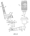
- the pole shaft arm 103 ( Figure 11) includes a pivot member 123 pivotally captured within the longitudinal slot 121.
- the pivot point 123 of the pole shaft arm 103 engages the end 125 of the longitudinal slot 121 when the separable contacts 51 ( Figure 2) are closed and the handle 47 is in the position of Figure 11.
- the handle leg 107 moves the upper link 105 in an upward (with respect to Figure 11) longitudinal direction.
- the pole shaft 60 pivots the bell crank arm 59 thereof clockwise (with respect to Figure 11) to open the separable contacts 51 (Figure 2) of the vacuum interrupter 13.
- the pole shaft 60 also, pivots the pole shaft arm 65 ( Figure 6A) to move the armature 63 of the linear actuator 50 (Figure 6B) upward (with respect to Figure 6B), in order to open the same.
- the operating mechanism opening spring 67 when charged ( Figure 12), biases a pole shaft arm 127 ( Figures 6A-6B and 12) with a first force.
- the linear actuator 50 ( Figures 6A-6B, 12 and 14) includes a magnet 185 having a second force that is greater than that first force until the longitudinal slot end 125 sufficiently pivots the pole shaft arm 103, which pivots the pole shaft 60 and the arm 65 thereof to move the linear actuator armature 63, in order to open the separable contacts 51.
- the actuator box assembly 95 of Figures 3 and 4 includes a floor closer lever 131 and a floor tripper lever 133.
- the lever 131 is normally biased downward (with respect to Figures 3 and 4) by spring 135, while the lever 133 is normally biased upward (with respect to Figures 3 and 4) by spring 137.
- the lever 131 is, however, allowed to go upward, with respect to Figures 3 and 4, whenever the circuit breaker 1 is fully withdrawn from a draw out cradle (not shown).
- the lever 131 normally rides in a groove (not shown) in the draw out cradle.
- the groove has a gap (not shown) at the fully withdrawn position (not shown) that allows such upward movement as manually initiated by an operator.
- a surface of the lever 131 actuates a close switch 139 to close a normally open close contact 141 ( Figure 5; switch 4).
- the lever 133 normally rides in a groove (not shown) in the draw out cradle. The shape of the groove moves the lever 133 downward (with respect to Figures 3 and 4) whenever the circuit breaker 1 is racked in or out of the draw out cradle.
- a surface of the lever 133 actuates a trip free switch 143 to open a normally closed contact 145 ( Figure 5; switch 2) and actuates a prevent close switch 147 to close a normally open contact 149 ( Figure 5; switch 3).
- These contacts 149 and 145 respectively open the circuit breaker 1 and prevent closing thereof.
- Figure 5 shows the wiring of the trip unit controller 71.
- a suitable power source 151 e . g ., without limitation, 100-240 VAC; 100-300 VDC
- the two DC power supplies 157,159 in this example each provide +48 VDC outputs, which are summed to provide +96 VDC at inputs 161 of the controller 71.
- the operating mechanism 33 of the circuit breaker 1 ( Figure 1) includes auxiliary switches (not shown) which provide AUX 1 and AUX 2 signals at 163 that are open when the circuit breaker 1 is open, and which provide AUX 3 and AUX 4 signals at 165 that are closed when the circuit breaker 1 is open.
- the contact 93 is the micro-switch normally closed contact, which inhibits the close input 83 when the handle 47 is partially actuated ( Figures 9 and 11).
- the prevent close contact 145 inhibits the close input 83 (switch 2) when the circuit breaker 1 is racked in or out and the lever 133 actuates the trip free switch 143.
- the close input 83 is activated from any of the remote close contact 69, the close pushbutton 37 or the normally open close contact 141 (switch 4) as closed when the lever 131 actuates the close switch 139.
- the first open input 85 is activated in response to closure of the remote open contact 75.
- the second open input 87 is activated in response to closure of the open pushbutton 38 or to closure of the contact 149 in response to the prevent close switch 147.
- the controller 71 preferably includes a circuit (not shown) that maintains a reserve charge on capacitors 167,169,171 for powering the closing coil 73 through outputs 173 that drive the close signal 79.
- the controller 71 also drives outputs 175 to illuminate the first LED 39 whenever the three capacitors 167,169,171 are fully charged.
- the controller 71 further drives outputs 177 to illuminate the second LED 40 to indicate circuit breaker wellness.
- FIGS 6A and 6B show the three vacuum interrupters 13 (as best shown in Figure 2), the pole shaft 60, the operating arms 65,103,127 thereof, the linear actuator 50, the emergency trip lever handle 47 and the opening spring 67.
- the cavities 9A,9B,9C house the three pole mechanisms 11, which include the three vacuum interrupters 13.
- Each of the vacuum interrupters 13 has a moveable stem mechanism 179 mechanically connected to the moveable contact of the separable contacts 51.
- Each of the moveable stem mechanisms 179 is mechanically connected through a corresponding one of the insulator/compression springs 57 to a corresponding one of the pole shaft bell crank arms 59 ( Figure 2).
- the pole shaft operating arms 65,103,127 engage the linear actuator armature 63, the link member 101 of the linkage 97 and the opening spring 67, respectively.
- Figure 7 shows the pivotable emergency trip lever 47, the linkage 97, the pole shaft 60 and the vacuum interrupter 13 in the normal closed position.
- the handle portion 99 of the emergency trip lever 47 is in its at rest or normal position, and the normally closed micro-switch contact 93 ( Figure 5) is in the closed position.
- the handle portion 99 of the emergency trip lever 47 is in its at rest or normal position, and the normally closed micro-switch contact 93 ( Figure 5) is in the closed position.
- the pole shaft 60 and the vacuum interrupter 13 are in the open position.
- the pivot member 123 of the pole shaft arm 103 remains pivotally captured within the longitudinal slot 121 of the link member 101, albeit shifted upward (with respect to Figures 8 and 11) above the end 125 ( Figure 11) of that slot 121.
- the micro-switch engagement position of the handle portion 99 of Figure 8 is preferably substantially closer to the normal position of Figure 7 than to the open position of Figure 10.
- Figure 9 is similar to Figure 8 except that the handle portion 99 of the emergency trip lever 47 is slightly and sufficiently pivoted in the direction 181, in order to open the normally closed micro-switch contact 93 (Figure 5; switch 1) and inhibit the close input 83 ( Figure 5) of the controller 71, thereby preventing a close signal from reaching such controller.
- Figure 10 is similar to Figure 9 except that the handle portion 99 of the emergency trip lever 47 is fully pivoted in the direction 183. This maintains the open state of the normally closed micro-switch contact 93 ( Figure 5; switch 1) and continues to inhibit the close input 83 ( Figure 5) of the controller 71, thereby preventing a close signal from reaching such controller. Otherwise, if the circuit breaker 1 were to close (e.g., in response to the remote close contact 69 of Figure 5), then the handle portion 99 would, otherwise, be quickly pulled back toward the circuit breaker 1 ( i.e. , toward the position of Figure 7) along with the user's hand. However, this is prevented by disabling the close input 83.
- Figure 11 is similar to Figure 9 except that the pole shaft 60 and the vacuum interrupter 13 are in the closed position.
- the handle portion 99 of the emergency trip lever 47 is slightly and sufficiently pivoted (counterclockwise with respect to Figure 11) from the normal position (Figure 7), in order to open the normally closed micro-switch contact 93 (Figure 5; switch 1) and inhibit the close input 83 ( Figure 5) of the controller 71, thereby preventing a close signal from reaching such controller.
- the vacuum interrupter 13 of Figure 11 is closed.
- the movement of the trip lever 47 and the linkage 97 causes the lower link 101, which engages the pole shaft arm 103 through the pivot member 123, to rotate the pole shaft 60 clockwise (with respect to Figure 11), in order to: (1) move the linear actuator armature 63 slightly upward (with respect to Figure 6B) in response to the pole shaft arm 65; and (2) move the moveable stem mechanism 179 slightly downward (with respect to Figure 11) in response to the bell crank arm 59.
- the holding force of the linear actuator magnet 185 ( Figure 14) is reduced sufficiently such that the opening spring 67 overcomes the now sufficiently reduced holding force of such linear actuator magnet.
- the handle portion 99 needs to move only a relatively small amount in order to open the circuit breaker 1.
- the opening spring 67 provides the force to completely open the circuit breaker 1. Otherwise, the force of the opening spring 67 is normally overcome by the normal magnetic holding force of the magnet 185 that maintains the closed position of the separable contacts 51.
- Figure 12 shows the linear actuator 50, pole shaft 60, opening spring 67 and the vacuum interrupter 13 in the closed position with the opening spring 67 having been charged in response to the energized closing coil 73 of the linear actuator 50.
- Figure 13 is similar to Figure 12 except that the linear actuator 50, pole shaft 60, opening spring 67 and the vacuum interrupter 13 are in the open position with the opening spring 67 being discharged.
- Figure 14 shows the linear actuator 50 of Figures 6A-6B and 14 including the closing coil 73, the opening coil 77, the magnet 185 and the armature 63, which forms an external drive rod or plunger.
- the armature 63 is connected to a steel plate 187 that is attracted, as shown on the left side of Figure 14 by the magnet 185 or by the energized state of the closing coil 73.
- the steel plate 187 is repelled, as shown on the right side of Figure 14 in phantom line drawing, by the energized state of the opening coil 77.
- the linear actuator 50 may include a second opening coil, such as 77A, that may be advantageously energized by another output (not shown) of the controller 71 ( Figure 5) (e.g., in response to failure of the first opening coil 77 or open signal 81).
- controller 71 of Figure 5 includes a suitable processor (e.g. , a microprocessor ( ⁇ P)), it will be appreciated that a combination of one or more of analog, digital and/or processor-based circuits may be employed.
- a suitable processor e.g. , a microprocessor ( ⁇ P)
- ⁇ P microprocessor
Abstract
Description
- This invention pertains generally to circuit interrupters and, more particularly, to such circuit interrupters employing one or more pole mechanisms.
- Circuit interrupters provide protection for electrical systems from electrical fault conditions such as, for example, current overloads, short circuits and abnormal level voltage conditions. Typically, circuit interrupters include a spring powered operating mechanism which opens electrical contacts to interrupt the current through the conductors of an electrical system in response to abnormal conditions.
- Circuit interrupters, such as, for example, power circuit breakers for systems operating above about 1,000 volts typically utilize vacuum interrupters as the switching devices. For the higher voltages, or for a more compact arrangement, each vacuum interrupter is housed in a separate pod molded of an electrically insulative material, such as a polyglass. These molded pods, in turn, are bolted to a metal box containing the operating mechanism. The metal box is grounded to isolate the operating mechanism from the line voltage of the power circuit. Manual controls for the operating mechanism are accessible at the front face of the metal box. See, for example, U.S. Patent No. 6,373,358.
- Vacuum circuit interrupter apparatus include separable main contacts disposed within an insulating housing. Generally, one of the contacts is fixed relative to both the housing and to an external electrical conductor which is interconnected with the circuit to be controlled by the circuit interrupter. The other contact is moveable. In the case of a vacuum circuit interrupter, the moveable contact assembly usually comprises a stem of circular cross-section having the contact at one end enclosed within a vacuum chamber and a driving mechanism at the other end which is external to the vacuum chamber. An operating rod assembly comprising a push rod, which is fastened to the end of the stem opposite the moveable contact, and a driving mechanism provide the motive force to move the moveable contact into or out of engagement with the fixed contact.
- The operating rod assembly is operatively connected to a latchable operating mechanism which is responsive to an abnormal current condition. When an abnormal condition is reached, the latchable operating mechanism becomes unlatched which causes the operating rod to move to the open position. The motion of the operating rod, in turn, causes a contact bell crank to rotate and this controls motion of the moveable contact.
- Compression springs are provided in connection with the operating rod assembly in order to be able to separate the moveable contact from the fixed contact and to assure the necessary force so that the contacts will not accidentally open under inappropriate conditions. In addition, when appropriate circumstances requiring interruption of the circuit do arise, an adequate force is needed to open the contacts with sufficient speed. If the contacts do not open quickly, then there is a risk of the contacts welding together and failure to interrupt the current.
- Vacuum interrupters are typically used, for instance, to reliably interrupt medium voltage alternating current (AC) currents and, also, high voltage AC currents of several thousands of amperes or more. Typically, one vacuum interrupter is provided for each phase of a multi-phase circuit and the vacuum interrupters for the several phases are actuated simultaneously by a common latchable operating mechanism.
- United States Patent Application Publication No. 2004/0118815 discloses an electrical interrupter apparatus including an interruption device, an insulation member, a base, a driving system and a linkage mechanism. A plurality of the electrical interrupter apparatuses may be incorporated into a circuit breaker, such as a 72.5 kV outdoor circuit breaker or other circuit breaker. The driving system includes a drive unit and a return spring. The drive unit is mounted within the base and can be any of a wide variety of mechanical devices suited to rapidly provide a sufficient level of force at a sufficient speed to operate the interruption device in an appropriate fashion. The drive unit may be of a variety of different configurations, and may be, for instance, a motor, a solenoid, a permanent magnet linear actuator, or other appropriate device.
- U.S. Patent No. 6,362,445 discloses a breaker module comprising a vacuum interrupter/linear actuator assembly. The vacuum interrupter portion of the breaker module is a conventional circuit breaker vacuum interrupter design including a moveable contact stem/push rod assembly that is connected to the armature of an in-line actuator, which drives the moveable contact into or out of engagement with a stationary contact in response to an input of an appropriate drive signal. The in-line actuator is of conventional design and consists of either one or two electrically wound coils wound around a magnetically permeable, hollow form positioned adjacent a hollow rare earth magnet. In the single coil design, voltage of a given polarity is applied to the coil to move the armature in a first direction and voltage of the opposite polarity is applied to the coil to move the armature in the opposite direction. In the two coil design, the magnet is interposed between the two coils and the armature is disposed in the hollow center. Voltage is applied to the first coil in a first direction to cause movement of the armature in one direction and voltage is applied to the second coil in the opposite direction to cause opposite movement of the armature.
- In the event of a loss of power or other failure, there is a need to permit an operator to manually open the vacuum interrupter.
- There is also a need for manual operation that is safe and reliable.
- Accordingly, there is room for improvement in vacuum circuit interrupters employing an actuator.
- These needs and others are met by the present invention, which provides a linear actuator circuit interrupter including an integral emergency trip member for use in case of a power loss. An operator employs the emergency trip member to open the circuit interrupter by pivoting the member towards the operator.
- As another aspect of the invention, in the event that a close signal is initiated while the operator is holding the emergency trip member, then the member may be, otherwise, violently forced back toward the circuit interrupter along with the operator's hand. The circuit interrupter includes a normally closed micro-switch in the close circuit thereof. The micro-switch normally closed contact is opened by movement of the circuit interrupter emergency trip member. When the emergency trip member is slightly pulled by an operator, the micro-switch normally closed contact switches to an open state, in order to disable a close signal in the close circuit. The close signal may originate, for example, from a close pushbutton, a close switch or an incoming close signal from an external source.
- In accordance with one aspect of the invention, a circuit interrupter comprises: a housing having an opening; at least one pole mechanism comprising separable contacts; an operating mechanism adapted to open and close the separable contacts of the at least one pole mechanism, the operating mechanism being supported by the housing; an actuator cooperating with the operating mechanism to open and close the separable contacts, the actuator being responsive to a close signal to close the separable contacts; a member protruding through the opening of the housing and cooperating with the operating mechanism to open the separable contacts when moved from a first position to a second position; a close circuit including an input inputting the close signal; and a switch including an operator and a contact electrically connected in series with the input of the close circuit, the operator being engaged by the member to open the contact in response to partial movement of the member from the first position toward the second position.
- The member may be a pivotable emergency trip lever protruding through the opening of the housing and cooperating with the operating mechanism and the actuator to trip open the separable contacts when pivoted to the second position.
- The pivotable emergency trip lever may include a normal position as the first position, an open position as the second position and an engagement position between the normal position and the open position. The pivotable emergency trip lever may engage the operator of the switch in the engagement position.
- The engagement position is preferably substantially closer to the normal position than the open position.
- The actuator may be a linear actuator including an armature moveable in a longitudinal direction. The at least one pole mechanism may include at least one vacuum interrupter having a moveable stem mechanism. The operating mechanism may include a pole shaft having an arm engaging the moveable stem mechanism and another arm engaging the armature of the linear actuator.
- The at least one pole mechanism may include a plurality of vacuum interrupters having a plurality of movable stem mechanisms. The operating mechanism may include a pole shaft having a first arm, a second arm and a plurality of third arms each of which engages a corresponding one of the movable stem mechanisms. The linear actuator may include an armature engaging the second arm of the pole shaft. The member may be a pivot member including a linkage between the pivot member and the operating mechanism to open the separable contacts when the pivot member is pivoted to the second position. The linkage may include a link member engaging the first arm of the pole shaft.
- The pivot member may include a leg. The linkage may include a first link pivotally mounted to the leg of the pivot member, a second link pivotally mounted to the first link, and the link member pivotally mounted to the second link.
- The link member may include a longitudinal slot. The first arm of the pole shaft may include a pivot point pivotally captured within the longitudinal slot.
- The second link may include a first pivot point pivotally mounted to the first link, a second pivot point pivotally mounted to the link member and a third pivot point pivotally mounted to the housing.
- The longitudinal slot may include an end. The pivot point of the first arm of the pole shaft may engage the end of the longitudinal slot when the separable contacts are closed. When the pivot member is pivoted to the second position, the leg of the pivot member moves the first link in a longitudinal direction, which pivots the second link about the third pivot point, which moves the link member in the longitudinal direction, in order that the end of the longitudinal slot pivots the first arm of the pole shaft, the pole shaft pivoting the second arm thereof to move the armature of the linear actuator. The operating mechanism may include an opening spring biasing the pole shaft with a first force. The linear actuator may include a magnet having a second force that is greater than the first force until the end of the longitudinal slot pivots the first arm of the pole shaft, which pivots the second arm thereof to move the armature of the linear actuator, in order to open the separable contacts.
- As another aspect of the invention, a power circuit interrupter comprises: a housing having an opening; at least one vacuum interrupter comprising separable contacts; an operating mechanism adapted to open and close the separable contacts of the at least one vacuum interrupter, the operating mechanism being supported by the housing; a linear actuator cooperating with the operating mechanism to open and close the separable contacts, the linear actuator being responsive to a close signal to close the separable contacts; a pivot member protruding through the opening of the housing and cooperating with the operating mechanism and the linear actuator to open the separable contacts when pivoted from a first position to a second position; a close circuit including an input inputting the close signal; and a switch including an operator and a contact electrically connected in series with the input of the close circuit, the operator being engaged by the pivot member to open the contact in response to partial pivoting of the pivot member from the first position toward the second position.
- As another aspect of the invention, a power circuit interrupter comprises: a housing having an opening; at least one vacuum interrupter including separable contacts; an operating mechanism adapted to open and close the separable contacts of the at least one vacuum interrupter, the operating mechanism being supported by the housing; a linear actuator cooperating-with the operating mechanism to open and close the separable contacts; a pivot member protruding through the opening of the housing; and a linkage between the pivot member and the operating mechanism to open the separable contacts when the pivot member is pivoted to an open position.
- A full understanding of the invention can be gained from the following description of the preferred embodiments when read in conjunction with the accompanying drawings in which:
- Figure 1 is a front isometric view of a circuit breaker in accordance with the invention with the cover exploded to show internal structures.
- Figure 2 is a longitudinal vertical section through the circuit breaker of Figure 1.
- Figure 3 is a side isometric view of an actuator box assembly of the circuit breaker of Figure 1.
- Figure 4 is another side isometric view of the actuator box assembly of Figure 3.
- Figure 5 is a block diagram of the wiring of the controller of the circuit breaker of Figure 1.
- Figure 6A is a plan view of the vacuum interrupters, pole shaft, operating arms, linear actuator, emergency trip lever and opening spring of the circuit breaker of Figure 1.
- Figure 6B is a vertical elevation view of the vacuum interrupters, pole shaft, operating arms, linear actuator, emergency trip lever and opening spring of the circuit breaker of Figure 1.
- Figure 7 is a simplified vertical side elevation view of the pivotable emergency trip lever, linkage, pole shaft and vacuum interrupter of Figure 1 in the closed position.
- Figure 8 is a simplified vertical side elevation view of the pivotable emergency trip lever, linkage, pole shaft and vacuum interrupter of Figure 1 in the open position.
- Figure 9 is a simplified vertical side elevation view of the pivotable emergency trip lever, linkage, pole shaft and vacuum interrupter of Figure 1 in the open position with the micro-switch in the open position and the emergency trip lever in the engagement position.
- Figure 10 is a simplified vertical side elevation view of the pivotable emergency trip lever, linkage, pole shaft and vacuum interrupter of Figure 1 in the open position with the micro-switch in the open position and the emergency trip lever in the fully open position.
- Figure 11 is a simplified vertical side elevation view of the pivotable emergency trip lever, linkage, pole shaft and vacuum interrupter of Figure 1 in the closed position with the micro-switch in the open position and the emergency trip lever moving from the closed position.
- Figure 12 is a simplified vertical side elevation view of the linear actuator, pole shaft, opening spring and vacuum interrupter of Figure 1 in the closed position.
- Figure 13 is a simplified vertical side elevation view of the linear actuator, pole shaft, opening spring and vacuum interrupter of Figure 1 in the open position.
- Figure 14 is a vertical sectional view of the linear actuator of Figure 1.
- The present invention is described in association with a power vacuum circuit breaker, although the invention is applicable to a wide range of circuit interrupters, including, but not limited to, other circuit breakers, load break switches, and switch disconnects.
- Referring to Figure 1, a three-pole power
vacuum circuit breaker 1 includes a moldedinsulative casing 3 divided into arear section 5 and a forward section 7. An example of thecasing 3 and therear section 5 is disclosed in U.S. Patent No. 6,373,358, which is incorporated by reference herein. Therear casing 5 is preferably molded as a single piece with a plurality of pole cavities 9 (one of which is shown in Figure 2). Theexemplary circuit breaker 1 has threesuch pole cavities pole cavities 9 houses apole mechanism 11, which includes avacuum interrupter 13 as is shown in Figure 2. - The
power circuit breaker 1 further includes anoperating mechanism 33 which is attached to the front of the forward section 7 of the moldedinsulative casing 3. Theoperating mechanism 33 is enclosed by acover 35, which is preferably molded of an insulative material, again such as glass polyester. Theoperating mechanism 33 includes controls on its front face such as thepushbuttons 37,38 (Figure 5) andindicators 39,40 (Figure 5) which are accessible through twoopenings cover 35. Atrip unit 43 mounted on the front of theoperating mechanism 33 is accessible through anotheropening 45 in thecover 35. In addition, a member, such ashandle 47 for manually tripping open theoperating mechanism 33, is accessible through an opening, such asslot 49 in thecover 35. In accordance with an important aspect of the invention, thehandle 47 is a pivot member or pivotable emergency trip lever, which cooperates with theoperating mechanism 33 and a linear actuator 50 (Figures 6A-6B and 14) (e.g., a solenoid; a magnetic actuator; an in-line actuator) to trip open thevacuum interrupters 13 when pivoted to an open position (Figure 10). - As best shown in Figure 2, each of the
vacuum interrupters 13 hasseparable contacts 51 housed in avacuum bottle 53. The upper or fixed contact of theseparable contacts 51 is electrically connected to aline conductor 55, which extends rearward for connection to a utility bus (not shown). The lower, or moveable, contact of theseparable contacts 51 is connected by aflexible shunt 54 to aload conductor 56, which likewise extends rearward for connection to a load bus (not shown). The moveable contact is mechanically connected through an insulator/compression spring 57, which provides electrical isolation and a spring bias, to an operating linkage in the form of a bell crank 59 of apole shaft 60. Thebell crank 59 is pivotally mounted in an electricallyconductive pan 61 which extends under the moldedinsulative casing 3. The forward ends of the bell crank 59 are connected to the armature 63 (Figures 6B and 14) of the linear actuator 50 (Figures 6A-6B and 14) by an arm 65 (Figure 6A) of thepole shaft 60. - The
operating mechanism 33 includes an opening spring 67 (Figures 6A-6B), which is charged through operation of thelinear actuator 50. Theoperating mechanism 33 is adapted to open and close theseparable contacts 51. Theseparable contacts 51 in each of the threevacuum interrupters 13 are also closed either manually by depressing theclose pushbutton 37, or remotely through a remote close contact 69 (Figure 5), either of which is received by the trip unit controller 71 (Figure 5), which responsively energizes the closingcoil 73 of thelinear actuator 50. Theseparable contacts 51 are opened utilizing the energy stored in theopening spring 67 of theoperating mechanism 33. Theseparable contacts 51 can also be opened automatically by thetrip unit controller 71 in response to certain current/time characteristics of current flowing through thecircuit breaker 1, manually by pushing the appropriateopen pushbutton 38, or remotely through a remote open contact 75 (Figure 5), any of which is received or generated by thecontroller 71, which energizes the openingcoil 77 of thelinear actuator 50. Thelinear actuator 50 cooperates with theoperating mechanism 33 to open and close theseparable contacts 51, is responsive to aclose signal 79 to close such contacts, and is response to anopen signal 81 to open those contacts. Thecontroller 71 drives theclose signal 79 responsive to aclose input 83 and drives theopen signal 81 responsive to openinputs - Referring to Figures 3 and 5, in accordance with another important aspect of the
circuit breaker 1, a switch, such asmicro-switch 89, includes anoperator 91 and a contact 93 (Figure 5; switch 1) electrically connected in series with theclose input 83 of thecontroller 71. Theoperator 91 is engaged by the pivot member handle 47 to open thecontact 93 in response to partial movement of thehandle 47 from its first or normal position (Figure 7) toward the open position (Figure 10). - Referring now to Figures 3 and 4, an
actuator box assembly 95 is shown. The pivot member handle 47 includes alinkage 97 between ahandle portion 99 and the operating mechanism 33 (Figure 1) to open the separable contacts 51 (Figure 2) when thehandle portion 99 is pivoted to the open position of Figure 10. As best shown in Figure 11, thelinkage 97 includes alink member 101 engaging anarm 103 of thepole shaft 60. As thehandle 47 pivots from the normal position (Figure 7) to an engagement position (Figures 9 and 11) between that normal position and the open position (Figure 10), thelinkage 97 in general, and theupper link 105 in particular, engages theswitch operator 91 in that engagement position, thereby causing the normally closed (NC) contact 93 (Figure 5) to open in response to partial movement of thehandle 97 toward the open position at the engagement position (Figures 9 and 11). - The
linkage 97 includes theupper link 105 pivotally mounted to aleg 107 of thehandle 47 bypivot member 109, anintermediate link 111 pivotally mounted to theupper link 105 bypivot member 113, and thelink member 101 pivotally mounted to theintermediate link 111 bypivot member 115. The end of theintermediate link 111 opposite thepivot member 113 is pivotally mounted to aframe 117 of the actuator box assembly 95 (Figure 3) by apivot member 119. Thelink member 101 includes alongitudinal slot 121. The pole shaft arm 103 (Figure 11) includes apivot member 123 pivotally captured within thelongitudinal slot 121. - The
pivot point 123 of thepole shaft arm 103 engages theend 125 of thelongitudinal slot 121 when the separable contacts 51 (Figure 2) are closed and thehandle 47 is in the position of Figure 11. When thehandle 47 is pivoted to the open position (Figure 10), thehandle leg 107 moves theupper link 105 in an upward (with respect to Figure 11) longitudinal direction. This pivots theintermediate link 111 clockwise (with respect to Figure 11) about thepivot member 119, which, in turn, moves thelink member 101 in the same upward longitudinal direction, in order that theend 125 of thelongitudinal slot 121 pivots thepole shaft arm 103 clockwise (with respect to Figure 11). Thepole shaft 60, in turn, pivots the bell crankarm 59 thereof clockwise (with respect to Figure 11) to open the separable contacts 51 (Figure 2) of thevacuum interrupter 13. Thepole shaft 60, also, pivots the pole shaft arm 65 (Figure 6A) to move thearmature 63 of the linear actuator 50 (Figure 6B) upward (with respect to Figure 6B), in order to open the same. - As will be discussed below in connection with Figure 11, the operating
mechanism opening spring 67, when charged (Figure 12), biases a pole shaft arm 127 (Figures 6A-6B and 12) with a first force. The linear actuator 50 (Figures 6A-6B, 12 and 14) includes amagnet 185 having a second force that is greater than that first force until thelongitudinal slot end 125 sufficiently pivots thepole shaft arm 103, which pivots thepole shaft 60 and thearm 65 thereof to move thelinear actuator armature 63, in order to open theseparable contacts 51. - Although not part of the present invention, the
actuator box assembly 95 of Figures 3 and 4 includes a floorcloser lever 131 and afloor tripper lever 133. Thelever 131 is normally biased downward (with respect to Figures 3 and 4) byspring 135, while thelever 133 is normally biased upward (with respect to Figures 3 and 4) byspring 137. Thelever 131 is, however, allowed to go upward, with respect to Figures 3 and 4, whenever thecircuit breaker 1 is fully withdrawn from a draw out cradle (not shown). Thelever 131 normally rides in a groove (not shown) in the draw out cradle. The groove has a gap (not shown) at the fully withdrawn position (not shown) that allows such upward movement as manually initiated by an operator. In that upward position, a surface of thelever 131 actuates a close switch 139 to close a normally open close contact 141 (Figure 5; switch 4). Thelever 133 normally rides in a groove (not shown) in the draw out cradle. The shape of the groove moves thelever 133 downward (with respect to Figures 3 and 4) whenever thecircuit breaker 1 is racked in or out of the draw out cradle. In that downward position, a surface of thelever 133 actuates a trip free switch 143 to open a normally closed contact 145 (Figure 5; switch 2) and actuates a prevent close switch 147 to close a normally open contact 149 (Figure 5; switch 3). Thesecontacts circuit breaker 1 and prevent closing thereof. - Figure 5 shows the wiring of the
trip unit controller 71. A suitable power source 151 (e.g., without limitation, 100-240 VAC; 100-300 VDC) providesincoming V+ 153 and incoming V- 155 inputs to two direct current (DC) power supplies 157,159. The two DC power supplies 157,159 in this example each provide +48 VDC outputs, which are summed to provide +96 VDC atinputs 161 of thecontroller 71. Theoperating mechanism 33 of the circuit breaker 1 (Figure 1) includes auxiliary switches (not shown) which provideAUX 1 andAUX 2 signals at 163 that are open when thecircuit breaker 1 is open, and which provideAUX 3 andAUX 4 signals at 165 that are closed when thecircuit breaker 1 is open. - As was discussed above, the contact 93 (switch 1) is the micro-switch normally closed contact, which inhibits the
close input 83 when thehandle 47 is partially actuated (Figures 9 and 11). Similarly, the preventclose contact 145 inhibits the close input 83 (switch 2) when thecircuit breaker 1 is racked in or out and thelever 133 actuates the trip free switch 143. Otherwise, with both of the contacts 93,145 being normally closed, theclose input 83 is activated from any of the remote close contact 69, theclose pushbutton 37 or the normally open close contact 141 (switch 4) as closed when thelever 131 actuates the close switch 139. The firstopen input 85 is activated in response to closure of the remoteopen contact 75. The secondopen input 87 is activated in response to closure of theopen pushbutton 38 or to closure of thecontact 149 in response to the prevent close switch 147. - The
controller 71 preferably includes a circuit (not shown) that maintains a reserve charge on capacitors 167,169,171 for powering the closingcoil 73 throughoutputs 173 that drive theclose signal 79. Thecontroller 71 also drivesoutputs 175 to illuminate thefirst LED 39 whenever the three capacitors 167,169,171 are fully charged. Thecontroller 71further drives outputs 177 to illuminate thesecond LED 40 to indicate circuit breaker wellness. - Figures 6A and 6B show the three vacuum interrupters 13 (as best shown in Figure 2), the
pole shaft 60, the operating arms 65,103,127 thereof, thelinear actuator 50, the emergency trip lever handle 47 and theopening spring 67. As was discussed above in connection with Figures 1 and 2, thecavities pole mechanisms 11, which include the threevacuum interrupters 13. Each of thevacuum interrupters 13 has amoveable stem mechanism 179 mechanically connected to the moveable contact of theseparable contacts 51. Each of themoveable stem mechanisms 179 is mechanically connected through a corresponding one of the insulator/compression springs 57 to a corresponding one of the pole shaft bell crank arms 59 (Figure 2). As was discussed above, the pole shaft operating arms 65,103,127 engage thelinear actuator armature 63, thelink member 101 of thelinkage 97 and theopening spring 67, respectively. - Figure 7 shows the pivotable
emergency trip lever 47, thelinkage 97, thepole shaft 60 and thevacuum interrupter 13 in the normal closed position. Thehandle portion 99 of theemergency trip lever 47 is in its at rest or normal position, and the normally closed micro-switch contact 93 (Figure 5) is in the closed position. - In Figure 8, the
handle portion 99 of theemergency trip lever 47 is in its at rest or normal position, and the normally closed micro-switch contact 93 (Figure 5) is in the closed position. This allows a close signal at the close input 83 (Figure 5) to be received by thecontroller 71, in order to responsively drive through the controller outputs 173 theclose signal 79 to the closingcoil 73. In this position, thepole shaft 60 and thevacuum interrupter 13 are in the open position. Thepivot member 123 of thepole shaft arm 103 remains pivotally captured within thelongitudinal slot 121 of thelink member 101, albeit shifted upward (with respect to Figures 8 and 11) above the end 125 (Figure 11) of thatslot 121. The micro-switch engagement position of thehandle portion 99 of Figure 8 is preferably substantially closer to the normal position of Figure 7 than to the open position of Figure 10. - Figure 9 is similar to Figure 8 except that the
handle portion 99 of theemergency trip lever 47 is slightly and sufficiently pivoted in thedirection 181, in order to open the normally closed micro-switch contact 93 (Figure 5; switch 1) and inhibit the close input 83 (Figure 5) of thecontroller 71, thereby preventing a close signal from reaching such controller. - Figure 10 is similar to Figure 9 except that the
handle portion 99 of theemergency trip lever 47 is fully pivoted in thedirection 183. This maintains the open state of the normally closed micro-switch contact 93 (Figure 5; switch 1) and continues to inhibit the close input 83 (Figure 5) of thecontroller 71, thereby preventing a close signal from reaching such controller. Otherwise, if thecircuit breaker 1 were to close (e.g., in response to the remote close contact 69 of Figure 5), then thehandle portion 99 would, otherwise, be quickly pulled back toward the circuit breaker 1 (i.e., toward the position of Figure 7) along with the user's hand. However, this is prevented by disabling theclose input 83. - Figure 11 is similar to Figure 9 except that the
pole shaft 60 and thevacuum interrupter 13 are in the closed position. Here, again, thehandle portion 99 of theemergency trip lever 47 is slightly and sufficiently pivoted (counterclockwise with respect to Figure 11) from the normal position (Figure 7), in order to open the normally closed micro-switch contact 93 (Figure 5; switch 1) and inhibit the close input 83 (Figure 5) of thecontroller 71, thereby preventing a close signal from reaching such controller. Unlike the open position of the separable contacts 51 (Figure 2) of Figure 9, thevacuum interrupter 13 of Figure 11 is closed. As was discussed above, the movement of thetrip lever 47 and thelinkage 97 causes thelower link 101, which engages thepole shaft arm 103 through thepivot member 123, to rotate thepole shaft 60 clockwise (with respect to Figure 11), in order to: (1) move thelinear actuator armature 63 slightly upward (with respect to Figure 6B) in response to thepole shaft arm 65; and (2) move themoveable stem mechanism 179 slightly downward (with respect to Figure 11) in response to the bell crankarm 59. As a result of the first motion, above, the holding force of the linear actuator magnet 185 (Figure 14) is reduced sufficiently such that theopening spring 67 overcomes the now sufficiently reduced holding force of such linear actuator magnet. As a result, thehandle portion 99 needs to move only a relatively small amount in order to open thecircuit breaker 1. After the force of thelinear actuator magnet 185 is sufficiently reduced, theopening spring 67 provides the force to completely open thecircuit breaker 1. Otherwise, the force of theopening spring 67 is normally overcome by the normal magnetic holding force of themagnet 185 that maintains the closed position of theseparable contacts 51. - Figure 12 shows the
linear actuator 50,pole shaft 60, openingspring 67 and thevacuum interrupter 13 in the closed position with theopening spring 67 having been charged in response to the energizedclosing coil 73 of thelinear actuator 50. Figure 13 is similar to Figure 12 except that thelinear actuator 50,pole shaft 60, openingspring 67 and thevacuum interrupter 13 are in the open position with theopening spring 67 being discharged. - Figure 14 shows the
linear actuator 50 of Figures 6A-6B and 14 including the closingcoil 73, the openingcoil 77, themagnet 185 and thearmature 63, which forms an external drive rod or plunger. Thearmature 63 is connected to asteel plate 187 that is attracted, as shown on the left side of Figure 14 by themagnet 185 or by the energized state of the closingcoil 73. Alternatively, thesteel plate 187 is repelled, as shown on the right side of Figure 14 in phantom line drawing, by the energized state of the openingcoil 77. Although not shown in Figure 5, thelinear actuator 50 may include a second opening coil, such as 77A, that may be advantageously energized by another output (not shown) of the controller 71 (Figure 5) (e.g., in response to failure of thefirst opening coil 77 or open signal 81). - Although the
controller 71 of Figure 5 includes a suitable processor (e.g., a microprocessor (µP)), it will be appreciated that a combination of one or more of analog, digital and/or processor-based circuits may be employed. - While specific embodiments of the invention have been described in detail, it will be appreciated by those skilled in the art that various modifications and alternatives to those details could be developed in light of the overall teachings of the disclosure. Accordingly, the particular arrangements disclosed are meant to be illustrative only and not limiting as to the scope of the invention which is to be given the full breadth of the claims appended and any and all equivalents thereof.
-
- 1. Claims with numerals
- 2. Reference numerical list
- 3. Information disclosure statement
-
- 2
- three-pole power vacuum circuit breaker
- 3
- molded insulative casing
- 5
- rear section
- 7
- forward section
- 9
- plurality of pole cavities (9A,9B,9C)
- 11
- pole mechanism
- 13
- vacuum interrupter
- 33
- operating mechanism
- 35
- cover
- 37
- close pushbutton
- 38
- open pushbutton
- 39
- indicator
- 40
- indicator
- 41
- opening
- 42
- opening
- 43
- trip unit
- 47
- handle
- 49
- slot
- 50
- linear actuator
- 51
- separable contacts
- 53
- vacuum bottle
- 55
- line conductor
- 54
- flexible shunt
- 56
- load conductor
- 57
- insulator/compression spring
- 59
- bell crank
- 61
- electrically conductive pan
- 63
- armature
- 65
- arm
- 67
- opening spring
- 69
- remote close contact
- 71
- trip unit controller
- 73
- closing coil
- 75
- remote open contact
- 77
- opening coil
- 77A
- opening coil
- 79
- close signal
- 81
- open signal
- 83
- close input
- 85
- open input
- 87
- open input
- 89
- switch, such as micro-switch
- 91
- operator
- 93
- contact
- 95
- actuator box assembly
- 97
- linkage
- 99
- handle portion
- 101
- link member
- 103
- arm
- 105
- upper link
- 107
- leg
- 109
- pivot member
- 111
- intermediate link
- 113
- pivot member
- 115
- pivot member
- 117
- frame
- 119
- pivot member
- 121
- longitudinal slot
- 123
- pivot member
- 125
- end of the longitudinal slot
- 127
- pole shaft arm
- 131
- floor closer lever
- 133
- floor tripper lever
- 135
- spring
- 137
- spring
- 139
- close switch
- 141
- normally open close contact
- 143
- trip free switch
- 145
- normally closed contact
- 147
- prevent close switch
- 149
- normally open contact
- 151
- power source
- 153
- incoming V+ input
- 155
- incoming V- input
- 157
- direct current (DC) power supply
- 159
- DC power supply
- 161
- controller inputs
- 163
-
AUX 1 andAUX 2 signals - 165
-
AUX 3 andAUX 4 signals - 167
- capacitor
- 169
- capacitor
- 171
- capacitor
- 173
- outputs
- 175
- outputs
- 177
- outputs
- 179
- moveable stem mechanism
- 181
- direction
- 183
- direction
- 185
- magnet
- 187
- steel plate
Claims (27)
- A circuit interrupter (1) comprising:a housing (3) having an opening (49);at least one pole mechanism (13) comprising separable contacts (51);an operating mechanism (33) adapted to open and close the separable contacts of said at least one pole mechanism, said operating mechanism being supported by said housing;an actuator (50) cooperating with said operating mechanism to open and close said separable contacts, said actuator being responsive to a close signal (83,79) to close said separable contacts;a member (47) protruding through the opening of said housing and cooperating with said operating mechanism to open said separable contacts when moved from a first position to a second position;a close circuit (71) including an input inputting said close signal; anda switch (89) including an operator (91) and a contact (93) electrically connected in series with the input of said close circuit, said operator being engaged by said member to open said contact in response to partial movement of said member from said first position toward said second position.
- The circuit interrupter (1) of Claim 1 wherein said housing is a molded insulative casing (3).
- The circuit interrupter (1) of Claim 1 wherein said member is a pivotable emergency trip lever (47) protruding through the opening of said housing and cooperating with said operating mechanism and said actuator to trip open said separable contacts when pivoted to said second position.
- The circuit interrupter (1) of Claim 3 wherein said pivotable emergency trip lever includes a normal position as said first position, an open position as said second position and an engagement position between said normal position and said open position; and wherein said pivotable emergency trip lever engages the operator of said switch in said engagement position.
- The circuit interrupter (1) of Claim 4 wherein said engagement position is substantially closer to said normal position than said open position.
- The circuit interrupter (1) of Claim 1 wherein said switch is a micro-switch (89).
- The circuit interrupter (1) of Claim 1 wherein said close circuit further includes a close pushbutton (37) driving said close signal.
- The circuit interrupter (1) of Claim 1 wherein said close circuit further includes a close switch (141) driving said close signal.
- The circuit interrupter (1) of Claim 1 wherein said close circuit further includes an external signal (69) driving said close signal.
- The circuit interrupter (1) of Claim 1 wherein said at least one pole mechanism includes three pole mechanisms (13); and wherein said housing includes three pole cavities (9A,9B,9C) each of which houses one of said three pole mechanisms.
- The circuit interrupter (1) of Claim 1 wherein said actuator is a linear actuator (50) including an armature (63) moveable in a longitudinal direction; wherein said at least one pole mechanism includes at least one vacuum interrupter (13) having a moveable stem mechanism (179); and wherein said operating mechanism includes a pole shaft (60) having an arm (59) engaging the moveable stem mechanism and another arm (65) engaging the armature of said linear actuator.
- The circuit interrupter (1) of Claim 1 wherein said actuator is a linear actuator (50) including an armature (63) moveable in a longitudinal direction; wherein said at least one pole mechanism includes a plurality of vacuum interrupters (13) having a plurality of movable stem mechanisms (179); and wherein said operating mechanism includes a pole shaft (60) having a first arm (103), a second arm (65) and a plurality of third arms (59) each of which engages a corresponding one of said movable stem mechanisms (179); wherein said linear actuator includes an armature (65) engaging the second arm of said pole shaft; wherein said member is a pivot member (47) including a linkage (97) between said pivot member and said operating mechanism to open said separable contacts when said pivot member is pivoted to said second position; and wherein said linkage includes a link member (101) engaging the first arm (103) of said pole shaft.
- The circuit interrupter (1) of Claim 12 wherein said pivot member includes a leg (107); and wherein said linkage includes a first link (105) pivotally mounted to the leg of said pivot member, a second link (111) pivotally mounted to said first link, and said link member (101) pivotally mounted to said second link.
- The power circuit interrupter (1) of Claim 13 wherein said link member includes a longitudinal slot (121); and wherein the first arm of said pole shaft includes a pivot point (123) pivotally captured within said longitudinal slot.
- The power circuit interrupter (1) of Claim 14 wherein said second link includes a first pivot point (113) pivotally mounted to said first link, a second pivot point (115) pivotally mounted to said link member and a third pivot point (119) pivotally mounted to said housing.
- The power circuit interrupter (1) of Claim 15 wherein said longitudinal slot includes an end (125); wherein the pivot point of the first arm of said pole shaft engages the end of said longitudinal slot when said separable contacts are closed; wherein when said pivot member is pivoted to said second position, the leg of said pivot member moves said first link in a longitudinal direction, which pivots said second link about the third pivot point, which moves said link member in said longitudinal direction, in order that the end of said longitudinal slot pivots the first arm of said pole shaft, said pole shaft pivoting the second arm thereof to move the armature of said linear actuator; wherein said operating mechanism includes an opening spring (67) biasing the pole shaft with a first force; and wherein said linear actuator includes a magnet (185) having a second force that is greater than said first force until the end of said longitudinal slot pivots the first arm of said pole shaft, which pivots the second arm thereof to move the armature of said linear actuator, in order to open said separable contacts.
- The circuit interrupter (1) of Claim 1 wherein the contact of said switch is a normally closed contact (93) electrically connected in series with the input of said close circuit; and wherein said operator is engaged by said member to open said normally closed contact in response to partial movement of said member from said first position toward said second position.
- The circuit interrupter (1) of Claim 1 wherein said actuator includes a coil (73) driven by the close signal of said close circuit.
- A power circuit interrupter (1) comprising:a housing (3) having an opening (49);at least one vacuum interrupter (13) comprising separable contacts (51);an operating mechanism (33) adapted to open and close the separable contacts of said at least one vacuum interrupter, said operating mechanism being supported by said housing;a linear actuator (50) cooperating with said operating mechanism to open and close said separable contacts, said linear actuator being responsive to a close signal (83,79) to close said separable contacts;a pivot member (47) protruding through the opening of said housing and cooperating with said operating mechanism and said linear actuator to open said separable contacts when pivoted from a first position to a second position;a close circuit (71) including an input inputting said close signal; anda switch (89) including an operator (91) and a contact (93) electrically connected in series with the input of said close circuit, said operator being engaged by said pivot member to open said contact in response to partial pivoting of said pivot member from said first position toward said second position.
- A power circuit interrupter (1) comprising:a housing (3) having an opening (49);at least one vacuum interrupter (13) including separable contacts (51);an operating mechanism (33) adapted to open and close the separable contacts of said at least one vacuum interrupter, said operating mechanism being supported by said housing;a linear actuator (50) cooperating with said operating mechanism to open and close said separable contacts;a pivot member (47) protruding through the opening of said housing; anda linkage (97) between said pivot member and said operating mechanism to open said separable contacts when said pivot member is pivoted to an open position.
- The power circuit interrupter (1) of Claim 20 wherein said operating mechanism includes a pole shaft (60) having a first arm (103), a second arm (65) and a plurality of third arms (59); wherein said at least one vacuum interrupter is a plurality of vacuum interrupters (13); wherein each of said vacuum interrupters further includes a stem mechanism (179) responsive to a corresponding one of the third arms of said pole shaft; wherein said linear actuator includes an armature (63) engaging the second arm of said pole shaft; and wherein said linkage includes a link member (101) engaging the first arm of said pole shaft.
- The power circuit interrupter (1) of Claim 20 wherein said pivot member is a pivotable emergency trip lever (67) protruding through the opening of said housing and cooperating with said operating mechanism and said linear actuator to trip open said separable contacts when pivoted to said open position.
- The power circuit interrupter (1) of Claim 20 wherein said operating mechanism includes a pole shaft (60) having a first arm (103), a second arm (65) and at least one third arm (59); wherein each of said at least one vacuum interrupter further includes a stem mechanism (179) responsive to a corresponding one of the at least one third arm of said pole shaft; wherein said linear actuator includes an armature (63) engaging the second arm of said pole shaft; and wherein said linkage includes a link member (101) engaging the first arm of said pole shaft.
- The power circuit interrupter (1) of Claim 23 wherein said pivot member includes a leg (107); and wherein said linkage includes a first link (105) pivotally mounted to the leg of said pivot member, a second link (111) pivotally mounted to said first link, and said link member (101) pivotally mounted to said second link.
- The power circuit interrupter (1) of Claim 24 wherein said link member includes a longitudinal slot (121); and wherein the first arm of said pole shaft includes a pivot point (123) pivotally captured within said longitudinal slot.
- The power circuit interrupter (1) of Claim 25 wherein said second link includes a first pivot point (113) pivotally mounted to said first link, a second pivot point (115) pivotally mounted to said link member and a third pivot point (119) pivotally mounted to said housing.
- The power circuit interrupter (1) of Claim 26 wherein said longitudinal slot includes an end (125); wherein the pivot point of the first arm of said pole shaft engages the end of said longitudinal slot when said separable contacts are closed; wherein when said pivot member is pivoted to said open position, the leg of said pivot member moves said first link in a longitudinal direction, which pivots said second link about the third pivot point, which moves said link member in said longitudinal direction, in order that the end of said longitudinal slot pivots the first arm of said pole shaft to open said separable contacts.
Applications Claiming Priority (1)
| Application Number | Priority Date | Filing Date | Title |
|---|---|---|---|
| US10/918,524 US6930271B1 (en) | 2004-08-13 | 2004-08-13 | Circuit interrupter including linear actuator and manual pivot member |
Publications (1)
| Publication Number | Publication Date |
|---|---|
| EP1626425A1 true EP1626425A1 (en) | 2006-02-15 |
Family
ID=34827775
Family Applications (1)
| Application Number | Title | Priority Date | Filing Date |
|---|---|---|---|
| EP05017779A Withdrawn EP1626425A1 (en) | 2004-08-13 | 2005-08-16 | Circuit interrupter including linear actuator and manual pivot member |
Country Status (3)
| Country | Link |
|---|---|
| US (1) | US6930271B1 (en) |
| EP (1) | EP1626425A1 (en) |
| CN (1) | CN1737970A (en) |
Cited By (1)
| Publication number | Priority date | Publication date | Assignee | Title |
|---|---|---|---|---|
| WO2011085887A1 (en) * | 2010-01-18 | 2011-07-21 | Abb Technology Ag | Medium voltage circuit breaker |
Families Citing this family (39)
| Publication number | Priority date | Publication date | Assignee | Title |
|---|---|---|---|---|
| US7148677B2 (en) * | 2005-02-15 | 2006-12-12 | Eaton Corporation | Vacuum circuit interrupter including circuit monitoring leakage or loss of vacuum and method of monitoring a vacuum interrupter for leakage or loss of vacuum |
| US7280338B2 (en) * | 2005-05-12 | 2007-10-09 | Eaton Corporation | Power supply circuit, back-pack power supply module and circuit interrupter including the same |
| JP2007227766A (en) * | 2006-02-24 | 2007-09-06 | Toshiba Corp | Electromagnetic actuator |
| US7545245B2 (en) * | 2006-05-01 | 2009-06-09 | Eaton Corporation | Manual opening device and electrical switching apparatus employing the same |
| ITBG20060051A1 (en) | 2006-10-06 | 2008-04-07 | Abb Service S Rl | LOW VOLTAGE SWITCH WITH SEALED INTERCHANGEABLE POLES |
| US7631741B2 (en) * | 2006-12-11 | 2009-12-15 | Arrow Engine Company | Engine clutch actuator |
| US7630189B2 (en) * | 2007-05-17 | 2009-12-08 | Energie H.T. International Inc. | High voltage disconnecting switch control |
| US7999416B2 (en) * | 2008-04-14 | 2011-08-16 | Emergie H. T. International Inc. | Module for controlling a switch in a high voltage electrical substation |
| US20090277768A1 (en) * | 2008-05-08 | 2009-11-12 | Cooper Technologies Company | Low Oil Trip Assembly for a Fault Interrupter and Load Break Switch |
| US7936541B2 (en) * | 2008-05-08 | 2011-05-03 | Cooper Technologies Company | Adjustable rating for a fault interrupter and load break switch |
| US7920037B2 (en) * | 2008-05-08 | 2011-04-05 | Cooper Technologies Company | Fault interrupter and load break switch |
| US7952461B2 (en) * | 2008-05-08 | 2011-05-31 | Cooper Technologies Company | Sensor element for a fault interrupter and load break switch |
| US8004377B2 (en) * | 2008-05-08 | 2011-08-23 | Cooper Technologies Company | Indicator for a fault interrupter and load break switch |
| US8013263B2 (en) * | 2008-08-14 | 2011-09-06 | Cooper Technologies Company | Multi-deck transformer switch |
| US8153916B2 (en) * | 2008-08-14 | 2012-04-10 | Cooper Technologies Company | Tap changer switch |
| US7872203B2 (en) | 2008-08-14 | 2011-01-18 | Cooper Technologies Company | Dual voltage switch |
| WO2010065733A1 (en) * | 2008-12-04 | 2010-06-10 | Cooper Technologies Company | Low force low oil trip mechanism |
| MX2011008472A (en) * | 2009-02-17 | 2011-11-18 | Abb Technology Ag | Manual tripping device for circuit breaker. |
| EP2312604B1 (en) * | 2009-10-14 | 2013-03-13 | ABB Technology AG | Electrical device with a multi-chamber housing |
| EP2341517B1 (en) * | 2009-12-29 | 2015-06-03 | ABB Technology AG | Medium voltage circuit breaker. |
| WO2012044873A1 (en) * | 2010-09-30 | 2012-04-05 | Dynapar Corporation | Operator-safe medium or higher voltage switch actuator |
| US8729416B2 (en) | 2012-01-23 | 2014-05-20 | Electro-Mechanical Corporation | Circuit breaker remote tripping |
| JP5901351B2 (en) * | 2012-03-01 | 2016-04-06 | 三菱電機株式会社 | Electromagnetic operation device |
| US10319538B1 (en) | 2013-03-15 | 2019-06-11 | Innovative Switchgear IP, LLC | Interrupter having unitary external terminal and internal contact |
| CN103165339B (en) * | 2013-03-28 | 2015-02-18 | 无锡市蓝虹电子有限公司 | Intelligent fast box type vacuum switch |
| JP6238620B2 (en) * | 2013-07-30 | 2017-11-29 | 三菱電機株式会社 | Electromagnet device |
| EP3317892B1 (en) * | 2015-06-30 | 2019-08-28 | Eaton Intelligent Power Limited | Combination of an electromagnetic switch, a controller and an external power supply |
| US9653224B2 (en) * | 2015-10-13 | 2017-05-16 | Eaton Corporation | Interruption apparatus employing actuator having movable engagement element |
| KR101870016B1 (en) * | 2016-02-16 | 2018-07-23 | 엘에스산전 주식회사 | Bypass Switch |
| US10614987B2 (en) | 2017-11-09 | 2020-04-07 | Eaton Intelligent Power Limited | Fully integrated manual opening mechanism on medium voltage circuit breaker |
| US10825625B1 (en) | 2019-06-07 | 2020-11-03 | Smart Wires Inc. | Kinetic actuator for vacuum interrupter |
| US11152174B2 (en) | 2019-06-19 | 2021-10-19 | Eaton Intelligent Power Limited | Dual thomson coil-actuated, double-bellows vacuum circuit interrupter |
| US11328884B2 (en) | 2019-06-26 | 2022-05-10 | Eaton Intelligent Power Limited | Variable-speed circuit breaker and switching method for same |
| US11107653B2 (en) | 2019-06-26 | 2021-08-31 | Eaton Intelligent Power Limited | Dual-action switching mechanism and pole unit for circuit breaker |
| CN111785564B (en) * | 2020-07-09 | 2022-07-12 | 河南智开智能科技有限公司 | Novel protection type permanent magnetism vacuum circuit breaker |
| US11183348B1 (en) | 2020-07-21 | 2021-11-23 | Eaton Intelligent Power Limited | Vacuum circuit interrupter with decelerator with integrated latch assembly |
| CN112700986B (en) * | 2020-12-14 | 2024-03-29 | 河南平高电气股份有限公司 | Three-phase mechanical linkage type circuit breaker |
| US11749477B2 (en) | 2021-04-21 | 2023-09-05 | Eaton Intelligent Power Limited | Vacuum circuit interrupter with dual plate actuation |
| US20230290588A1 (en) * | 2022-03-10 | 2023-09-14 | Eaton Intelligent Power Limited | Fully integrated manual open mechanism for mvdc hybrid circuit breaker |
Citations (3)
| Publication number | Priority date | Publication date | Assignee | Title |
|---|---|---|---|---|
| US6373358B1 (en) * | 2000-05-09 | 2002-04-16 | Eaton Corporation | Power circuit breaker having molded insulative casing with a dead front |
| US20040144757A1 (en) * | 2001-06-01 | 2004-07-29 | Rhein David A. | Electrical circuit interrupting device |
| US20050063107A1 (en) * | 2003-09-22 | 2005-03-24 | Benke James J. | Medium voltage vacuum circuit interrupter |
Family Cites Families (18)
| Publication number | Priority date | Publication date | Assignee | Title |
|---|---|---|---|---|
| US3567886A (en) * | 1968-02-16 | 1971-03-02 | Hugh C Ross | Circuit breaker operating means compressing cooperatively connected toggle pairs |
| SE410067B (en) * | 1974-04-02 | 1979-09-17 | Siemens Ag | DEVICE FOR DETECTING LACK OF OPERATION FOR VACUUM BREAKING CHAMBER |
| US4016385A (en) * | 1975-10-08 | 1977-04-05 | Bell Telephone Laboratories, Incorporated | High voltage transfer switch with cam controlled overlap during transfer |
| US4272687A (en) | 1979-03-05 | 1981-06-09 | Borkan William N | Power manageable circuit breaker |
| US4611620A (en) | 1981-04-02 | 1986-09-16 | Parker Hannifin Corporation | Hydraulic circuit breaker |
| US4471797A (en) | 1982-03-19 | 1984-09-18 | Parker-Hannifin Corporation | Hydraulic circuit breaker reset device |
| US4490593A (en) * | 1983-05-09 | 1984-12-25 | Square D Company | Arrangement for arc transfer in high amperage molded case circuit breaker |
| US5397868A (en) * | 1993-09-28 | 1995-03-14 | Eaton Corporation | Transfer switch |
| US5422453A (en) * | 1993-09-28 | 1995-06-06 | Eaton Corporation | Handle actuator for a circuit interrupter handle |
| US5652416A (en) | 1995-11-22 | 1997-07-29 | Onan Corporation | Mechanically held electrically or manually operated switch |
| US5628394A (en) * | 1996-03-25 | 1997-05-13 | Eaton Corporation | Switchgear with top mounted vertical takeoff tripping and spring release interlock |
| US5936817A (en) | 1998-05-11 | 1999-08-10 | Eaton Corporation | Electrical switching apparatus employing a circuit for selectively enabling and disabling a close actuator mechanism |
| US6373015B1 (en) | 2000-01-03 | 2002-04-16 | Eaton Corporation | Integral load connector module |
| US6242708B1 (en) | 2000-01-03 | 2001-06-05 | Eaton Corporation | Isolator switch |
| US6362445B1 (en) | 2000-01-03 | 2002-03-26 | Eaton Corporation | Modular, miniaturized switchgear |
| US6365993B1 (en) | 2000-04-07 | 2002-04-02 | Eaton Corporation | Round linear actuator utilizing flat permanent magnets |
| US6326872B1 (en) | 2000-05-09 | 2001-12-04 | Eaton Corporation | Power circuit breaker with air gap between molded insulative casing and grounded barrier insulating operating mechanism |
| US6770832B2 (en) | 2002-12-19 | 2004-08-03 | Eaton Corporation | Vacuum electrical interrupter with pull-to-close mechanism |
-
2004
- 2004-08-13 US US10/918,524 patent/US6930271B1/en active Active
-
2005
- 2005-08-12 CN CN200510109848.9A patent/CN1737970A/en active Pending
- 2005-08-16 EP EP05017779A patent/EP1626425A1/en not_active Withdrawn
Patent Citations (3)
| Publication number | Priority date | Publication date | Assignee | Title |
|---|---|---|---|---|
| US6373358B1 (en) * | 2000-05-09 | 2002-04-16 | Eaton Corporation | Power circuit breaker having molded insulative casing with a dead front |
| US20040144757A1 (en) * | 2001-06-01 | 2004-07-29 | Rhein David A. | Electrical circuit interrupting device |
| US20050063107A1 (en) * | 2003-09-22 | 2005-03-24 | Benke James J. | Medium voltage vacuum circuit interrupter |
Cited By (2)
| Publication number | Priority date | Publication date | Assignee | Title |
|---|---|---|---|---|
| WO2011085887A1 (en) * | 2010-01-18 | 2011-07-21 | Abb Technology Ag | Medium voltage circuit breaker |
| US8842407B2 (en) | 2010-01-18 | 2014-09-23 | Abb Technology Ag | Medium voltage circuit breaker |
Also Published As
| Publication number | Publication date |
|---|---|
| CN1737970A (en) | 2006-02-22 |
| US6930271B1 (en) | 2005-08-16 |
Similar Documents
| Publication | Publication Date | Title |
|---|---|---|
| US6930271B1 (en) | Circuit interrupter including linear actuator and manual pivot member | |
| US7576957B2 (en) | Circuit interrupter including point-on-wave controller and voltage sensors | |
| US4025883A (en) | Modular integral motor controller | |
| EP1402548B1 (en) | Electrical circuit interrupting device | |
| US20070252599A1 (en) | Circuit interrupter including manual selector selecting different point-on-wave switching characteristics | |
| RU2251755C2 (en) | Circuit contact maker-breaker | |
| JP2894052B2 (en) | Circuit breaker | |
| JP2007504631A (en) | Power switch | |
| JPS6229031A (en) | Circuit danzokuki | |
| CA2785215A1 (en) | Circuit breaker remote tripping | |
| GB2166906A (en) | Circuit breaker | |
| ATE106159T1 (en) | SWITCHING MECHANISM FOR LOW VOLTAGE SWITCHGEAR. | |
| CA2464165C (en) | Remotely controllable circuit breaker including bypass magnet circuit | |
| CA2463225C (en) | Circuit breaker inducing mechanism for breaking tack weld | |
| US5614878A (en) | Two pole remote controlled circuit breaker | |
| CA2437111C (en) | Circuit breaker | |
| CA2408505A1 (en) | Power circuit breaker having molded insulative casing with a dead front | |
| CN100466141C (en) | Leakage circuit breaker | |
| WO2003012813A1 (en) | Remote control circuit breaker with a by-pass lead | |
| JP3771268B2 (en) | Overload protection device for switching contact of switch | |
| US20230268151A1 (en) | Circuit breaker having vacuum interrupters and single-phase control with magnetic actuators and associated method | |
| RU181455U1 (en) | VACUUM SWITCH | |
| SU1670741A1 (en) | Device for automatic switching-on of standby equipment | |
| JPH10223118A (en) | Circuit breaker | |
| Benke et al. | Medium Voltage Electro-Mechanical Linear Actuator Breaker |
Legal Events
| Date | Code | Title | Description |
|---|---|---|---|
| PUAI | Public reference made under article 153(3) epc to a published international application that has entered the european phase |
Free format text: ORIGINAL CODE: 0009012 |
|
| AK | Designated contracting states |
Kind code of ref document: A1 Designated state(s): AT BE BG CH CY CZ DE DK EE ES FI FR GB GR HU IE IS IT LI LT LU LV MC NL PL PT RO SE SI SK TR |
|
| AX | Request for extension of the european patent |
Extension state: AL BA HR MK YU |
|
| 17P | Request for examination filed |
Effective date: 20060330 |
|
| AKX | Designation fees paid |
Designated state(s): DE IT |
|
| 17Q | First examination report despatched |
Effective date: 20070207 |
|
| STAA | Information on the status of an ep patent application or granted ep patent |
Free format text: STATUS: THE APPLICATION IS DEEMED TO BE WITHDRAWN |
|
| 18D | Application deemed to be withdrawn |
Effective date: 20070619 |