EP1627687A2 - Liquid handling robot for well plates - Google Patents
Liquid handling robot for well plates Download PDFInfo
- Publication number
- EP1627687A2 EP1627687A2 EP05016744A EP05016744A EP1627687A2 EP 1627687 A2 EP1627687 A2 EP 1627687A2 EP 05016744 A EP05016744 A EP 05016744A EP 05016744 A EP05016744 A EP 05016744A EP 1627687 A2 EP1627687 A2 EP 1627687A2
- Authority
- EP
- European Patent Office
- Prior art keywords
- head
- robot
- tray
- liquid handling
- pipette tip
- Prior art date
- Legal status (The legal status is an assumption and is not a legal conclusion. Google has not performed a legal analysis and makes no representation as to the accuracy of the status listed.)
- Granted
Links
Images


Classifications
-
- B—PERFORMING OPERATIONS; TRANSPORTING
- B01—PHYSICAL OR CHEMICAL PROCESSES OR APPARATUS IN GENERAL
- B01L—CHEMICAL OR PHYSICAL LABORATORY APPARATUS FOR GENERAL USE
- B01L3/00—Containers or dishes for laboratory use, e.g. laboratory glassware; Droppers
- B01L3/02—Burettes; Pipettes
- B01L3/0275—Interchangeable or disposable dispensing tips
- B01L3/0279—Interchangeable or disposable dispensing tips co-operating with positive ejection means
-
- B—PERFORMING OPERATIONS; TRANSPORTING
- B01—PHYSICAL OR CHEMICAL PROCESSES OR APPARATUS IN GENERAL
- B01L—CHEMICAL OR PHYSICAL LABORATORY APPARATUS FOR GENERAL USE
- B01L9/00—Supporting devices; Holding devices
- B01L9/54—Supports specially adapted for pipettes and burettes
- B01L9/543—Supports specially adapted for pipettes and burettes for disposable pipette tips, e.g. racks or cassettes
-
- G—PHYSICS
- G01—MEASURING; TESTING
- G01N—INVESTIGATING OR ANALYSING MATERIALS BY DETERMINING THEIR CHEMICAL OR PHYSICAL PROPERTIES
- G01N35/00—Automatic analysis not limited to methods or materials provided for in any single one of groups G01N1/00 - G01N33/00; Handling materials therefor
- G01N35/0099—Automatic analysis not limited to methods or materials provided for in any single one of groups G01N1/00 - G01N33/00; Handling materials therefor comprising robots or similar manipulators
-
- G—PHYSICS
- G01—MEASURING; TESTING
- G01N—INVESTIGATING OR ANALYSING MATERIALS BY DETERMINING THEIR CHEMICAL OR PHYSICAL PROPERTIES
- G01N35/00—Automatic analysis not limited to methods or materials provided for in any single one of groups G01N1/00 - G01N33/00; Handling materials therefor
- G01N35/10—Devices for transferring samples or any liquids to, in, or from, the analysis apparatus, e.g. suction devices, injection devices
- G01N35/1081—Devices for transferring samples or any liquids to, in, or from, the analysis apparatus, e.g. suction devices, injection devices characterised by the means for relatively moving the transfer device and the containers in an horizontal plane
- G01N35/109—Devices for transferring samples or any liquids to, in, or from, the analysis apparatus, e.g. suction devices, injection devices characterised by the means for relatively moving the transfer device and the containers in an horizontal plane with two horizontal degrees of freedom
-
- B—PERFORMING OPERATIONS; TRANSPORTING
- B01—PHYSICAL OR CHEMICAL PROCESSES OR APPARATUS IN GENERAL
- B01L—CHEMICAL OR PHYSICAL LABORATORY APPARATUS FOR GENERAL USE
- B01L2200/00—Solutions for specific problems relating to chemical or physical laboratory apparatus
- B01L2200/14—Process control and prevention of errors
- B01L2200/143—Quality control, feedback systems
-
- B—PERFORMING OPERATIONS; TRANSPORTING
- B01—PHYSICAL OR CHEMICAL PROCESSES OR APPARATUS IN GENERAL
- B01L—CHEMICAL OR PHYSICAL LABORATORY APPARATUS FOR GENERAL USE
- B01L2300/00—Additional constructional details
- B01L2300/02—Identification, exchange or storage of information
-
- B—PERFORMING OPERATIONS; TRANSPORTING
- B01—PHYSICAL OR CHEMICAL PROCESSES OR APPARATUS IN GENERAL
- B01L—CHEMICAL OR PHYSICAL LABORATORY APPARATUS FOR GENERAL USE
- B01L2300/00—Additional constructional details
- B01L2300/08—Geometry, shape and general structure
- B01L2300/0809—Geometry, shape and general structure rectangular shaped
- B01L2300/0829—Multi-well plates; Microtitration plates
-
- G—PHYSICS
- G01—MEASURING; TESTING
- G01N—INVESTIGATING OR ANALYSING MATERIALS BY DETERMINING THEIR CHEMICAL OR PHYSICAL PROPERTIES
- G01N35/00—Automatic analysis not limited to methods or materials provided for in any single one of groups G01N1/00 - G01N33/00; Handling materials therefor
- G01N2035/00178—Special arrangements of analysers
- G01N2035/00277—Special precautions to avoid contamination (e.g. enclosures, glove- boxes, sealed sample carriers, disposal of contaminated material)
-
- G—PHYSICS
- G01—MEASURING; TESTING
- G01N—INVESTIGATING OR ANALYSING MATERIALS BY DETERMINING THEIR CHEMICAL OR PHYSICAL PROPERTIES
- G01N35/00—Automatic analysis not limited to methods or materials provided for in any single one of groups G01N1/00 - G01N33/00; Handling materials therefor
- G01N35/10—Devices for transferring samples or any liquids to, in, or from, the analysis apparatus, e.g. suction devices, injection devices
- G01N2035/1027—General features of the devices
- G01N2035/103—General features of the devices using disposable tips
-
- G—PHYSICS
- G01—MEASURING; TESTING
- G01N—INVESTIGATING OR ANALYSING MATERIALS BY DETERMINING THEIR CHEMICAL OR PHYSICAL PROPERTIES
- G01N35/00—Automatic analysis not limited to methods or materials provided for in any single one of groups G01N1/00 - G01N33/00; Handling materials therefor
- G01N35/10—Devices for transferring samples or any liquids to, in, or from, the analysis apparatus, e.g. suction devices, injection devices
- G01N35/1065—Multiple transfer devices
- G01N2035/1076—Multiple transfer devices plurality or independently movable heads
-
- Y—GENERAL TAGGING OF NEW TECHNOLOGICAL DEVELOPMENTS; GENERAL TAGGING OF CROSS-SECTIONAL TECHNOLOGIES SPANNING OVER SEVERAL SECTIONS OF THE IPC; TECHNICAL SUBJECTS COVERED BY FORMER USPC CROSS-REFERENCE ART COLLECTIONS [XRACs] AND DIGESTS
- Y10—TECHNICAL SUBJECTS COVERED BY FORMER USPC
- Y10T—TECHNICAL SUBJECTS COVERED BY FORMER US CLASSIFICATION
- Y10T436/00—Chemistry: analytical and immunological testing
- Y10T436/11—Automated chemical analysis
- Y10T436/113332—Automated chemical analysis with conveyance of sample along a test line in a container or rack
- Y10T436/114165—Automated chemical analysis with conveyance of sample along a test line in a container or rack with step of insertion or removal from test line
Definitions
- the invention relates to liquid handling robots for well plates which are used in biochemistry and microbiology for processing large numbers of samples in parallel.
- FIG. 1 is a perspective view of a liquid handling robot according to the prior art.
- the robot comprises a movable head 10 that is used for liquid handling and also has a mechanical manipulation capability.
- the head 10 is movable in three orthogonal axes, x, y and z, with respective motor positioners 12, 14 and 16. Head motion is controlled by a computer control system (not shown) via a control unit 15.
- the head 10 may also incorporates a camera (not shown) used to perform machine vision functions, such as bar code reading of well plates.
- the head 10 is movable over a main bed 18 of the apparatus on which well plates and other biological sample containers, such as Q-trays, petri dishes and omni-trays, can be arranged, usually within an experimental area 19.
- a waste chute 20 is incorporated in the main bed 18 and is flanked by stripping arm posts 21, the purpose of which is described below.
- the head 10 is provided with pincers 25 which are used to grip pipette tip trays. Using the pincers 25 and the positioners 12, 14 and 16, the head 10 can be used to move pipette tip trays around the apparatus as required.
- the head 10 is also provided with jaws 26 arranged in the horizontal plane for gripping well plates or other sample plates such as omni-trays Q-trays or petri dishes.
- FIG 2 is a perspective view of a pipette tip tray 34 loaded with pipette tips 22.
- the pipette tips 22 are loaded into trays to allow robotic handling.
- Each tray is a flat piece of stiff material, such as metal or plastic, with an array of through holes in a grid conforming to the desired well plate standard grid, the through holes having a diameter equal to part of the tapered neck portion of the pipette tips 22, so that pipette tips 22 seat in the through holes.
- the head is provided with an array of pipette tip receiving cones 24 with the array being conformant to the well plate type being processed, for example a 12 x 8 array for 96-well well plates.
- FIG. 3 shows a single pipette tip cone 24 together with an upper end of a pipette tip 22.
- Each cone 24 has a central capillary leading to a reservoir formed by a barrel and piston, in which the piston is slidable up and down in the barrel to provide a syringing action.
- the outer surfaces of the cones 24 are corrugated to assist pipette gripping.
- the cones are made of resilient material to aid formation of a liquid tight seal between themselves and the pipette tips 22 they are designed to receive.
- a pipette tip tray anvil 32 arranged on the main bed 18 of the apparatus there can be seen a pipette tip tray anvil 32.
- the anvil 32 is a plate with an array of through holes in a grid conforming to one of the well plate standard grids, the through holes having a diameter slightly larger than the outer diameter of the widest part of the pipette tips 22.
- a number of trays 34 loaded with unused pipette tips 22 are held in a shelved storage rack 36, sometimes referred to as a "hotel" in the art, with each tray arranged on one shelf and vertically adjacent shelves spaced far enough apart to avoid the pipette tips fouling each other when they are slid in and out of the shelves.
- the hotel is illustrated as having three racks, each with three shelves. A greater number of shelves would usually be provided in practice.
- the action of loading pipette tips 22 onto the liquid handling head 10 is now described.
- the head 10 is moved over to the pipette tip tray storage rack 36 and, using the pincers 25, one of the pipette tip trays 34 is taken out and placed on the anvil 32.
- the head 10 is then moved so that the array of cones 24 is aligned above the array of pipette tips 22.
- the head 10 is then driven down so that the (male) cones 24 mate with the (female) upper apertures of the pipette tips 22, the anvil 32 acting as an abutment surface to allow the pipette tips 22 to be pushed onto the cones 24.
- the head 10 is then raised away from the anvil 32 using the z-positioner 16 with each of the cones 24 now loaded with a pipette tip 22 ready for liquid handling.
- the head 10 includes a slotted plate (not shown), immediately above the cones 24 with the slots having a width greater than the maximum outer diameter of the cones and less than the maximum outer diameter of the pipette tips 22.
- the slotted plate is hinged to the main body of the liquid handling head 10. The hinging action allows ejection of pipette tips 22 from the cones 24 on which they are seated.
- the hinged slotted plate is actuated by a lever acting on the slotted plate being pushed onto the stripping posts 21 as the head 10 is driven down over the waste chute 20. The pipette tips are thus stripped off over the waste chute 20.
- the anvil-based pipette tip loading process is not always reliable.
- the loaded pipette tips can on occasion fall off their cones, especially during syringing out of the liquid reservoir. If this happens, the resultant spillage can destroy the integrity of a whole well plate, which may contain valuable reagents and contain samples obtained from several processing steps already performed.
- the liquid handling robot is not capable of performing other actions, such as gridding or picking, which necessitates transfer of the well plates to another machine if these actions need to be performed before or after the liquid handling actions. Each such transfer, carries a contamination risk, and is also inconvenient.
- an anvil apparatus for a liquid handling robot comprising: an apertured plate for receiving an array of pipette tips; a clamping arrangement for holding down a liquid handling head of the liquid handling robot above the apertured plate; and a drive for forcing the apertured plate and the liquid handling head together while the liquid handling head is held down by the clamping arrangement in order to push pipette tips onto the liquid handling head.
- the powered anvil of the invention is found to provide enhanced reliability, which is attributed to the fact that a controlled smooth action can be provided for pressing the pipette tips onto the liquid handling head. Moreover, by first clamping the liquid handling head to the anvil, a well defined driving force can be applied with a separate drive so that the driving force can be optimized for the pipette fitting action.
- the drive may comprise a jack arranged to push the apertured plate upwards from below.
- the jack can be implemented with a pneumatically actuated piston assembly. Many other solutions could also be adopted, for example based on motor drives.
- the clamping arrangement may comprise movable arms that are actuatable between clamping and free positions to clamp and release the liquid handling head.
- the array may conveniently conform to a well plate standard spacing, for example for a well plate having 96 wells or 384 wells.
- the pipette tip array need not be as large as a whole well plate array.
- the pipette tip array may be a 4 x 6 array, covering a quarter of a 96-well well plate which is made up of an 8 x 12 array of wells.
- a liquid handling robot comprising: an anvil apparatus according to the first aspect of the invention; and a liquid handling head having an array of cones for receiving pipette tips shaped to mate with the clamping arrangement of the anvil apparatus.
- a storage cassette for loaded pipette tip trays comprising: a storage shaft having an internal cross-section shaped and dimensioned to receive vertically stacked pipette tip trays loaded with pipette tips and to allow the pipette tip trays to slide up and down the storage shaft; and a tray retaining mechanism having a retention position in which a lowest one of the pipette tip trays, and thus pipette tip trays vertically stacked above it, are retained in the storage cassette, and a release position in which the pipette tip trays are free to slide down the storage shaft past the tray retaining mechanism.
- the tray retaining mechanism may include spring biasing which can be urged into the release position by an actuating force, but otherwise adopts the retention position.
- spring biasing which can be urged into the release position by an actuating force, but otherwise adopts the retention position.
- a variety of other movable retaining mechanisms could be used. For example, sliding catches drivable by motors between the two positions.
- a pipette tip tray dispenser comprising: a storage cassette according to the invention; and a base unit on which the storage cassette is mountable, the base unit comprising a vertically movable pipette tip tray carrier that can be raised to support the lowest pipette tip tray held in the storage cassette and lowered to carry the lowest pipette tip tray out of the storage shaft beyond the tray retaining mechanism.
- the carrier is preferably arranged so that its upward motion to support the lowest pipette tip tray held in the storage cassette moves the tray retaining mechanism from its retention position to its release position and its downward motion allows passage of the lowest pipette tip tray beyond the tray retaining mechanism before the tray retaining mechanism returns to its retention position, thereby allowing the lowest pipette tip tray to be dispensed.
- the carrier may advantageously lower the dispensed lowest pipette tip tray onto a conveyor for moving the pipette tip tray away from the storage cassette for subsequent use.
- the storage cassette is detachably arranged on the base unit.
- a strength of the pipette tip tray dispenser and storage cassette design is that the dispensing channels and storage cassettes can be used for different pipette tip sizes without any redesign. For example, if two dispensing channels are provided, one can be used with a storage cassette loaded with large volume pipette tips and the other with a storage cassette loaded with small volume pipette tips. A storage cassette loaded with small volume pipette tips installed in one dispensing channel could be swapped with a storage cassette loaded with large volume pipette tips without any reconfiguration of the mechanical components being necessary. The robot control system would however need to be informed.
- a liquid handling robot comprising a pipette tip tray dispenser according to the invention.
- the liquid handling robot may further comprise a head with a manipulator for removing pipette tip trays from the pipette tip tray dispenser.
- a robot for handling biological sample containers comprising: a head for carrying out processes on biological sample containers; a positioning apparatus for moving the head around the robot; and a parking station for parking the head, wherein the head is connected to the positioning apparatus by an attachment mechanism drivable between a clamped state, in which the head is secured to the positioning apparatus, and a released state, in which the head can be detached from the positioning apparatus and deposited in the park station.
- the park station preferably comprises a plurality of parking bays, each for parking one head. This allows different types of head to be stored ready for action, and also spare heads of the same type in case the head being used suffers a failure.
- the robot will typically be provided with multiple heads, for example two or more liquid handling heads, a mixture of liquid handling and pin heads, or two or more pin heads, thereby providing a flexible multi-purpose robot, capable of carrying out a variety of liquid handling, spotting, gridding and colony picking tasks.
- the attachment mechanism comprises a piston assembly arranged to actuate a knee joint connected to a latch, the knee joint adopting a bent position in the released state and straightened position in the clamped state.
- the piston assembly may advantageously include two piston cylinder units arranged in a push-me-pull-you configuration either side of the knee joint.
- the attachment mechanism may include a communication feed-through, and each head resident logic that allows the robot through the communication feed-through to receive identification data from any head that is attached to the positioning apparatus.
- the powered anvil, pipette tip tray dispenser and automated head attachment can be advantageously combined in a single liquid handling robot.
- the combination of automated pipette tip tray dispenser and powered anvil is a powerful combination which allows for rapid and reliable liquid handling of well plates using disposable pipette tips.
- Liquid handling is further enhanced by the ability to swap between multiple liquid handling heads in a fully automated fashion, the heads being specialized to perform different tasks.
- different liquid handling heads may be provided for large and small volume pipette tips, and the pipette tip tray dispenser can be loaded with two storage cassettes, one carrying large volume pipette tips and the other low volume pipette tips which are then independently dispensable through separate dispensing channels.
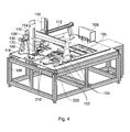
- FIG 4 is a perspective view of a liquid handling robot according to an embodiment of the invention.
- the robot comprises a movable head 110 that is used for liquid handling and also has a mechanical manipulation capability.
- the head 110 is movable in three orthogonal axes, x, y and z, with respective motor positioners 112, 114 and 116. Head motion is controlled by a computer control system (not shown).
- the head 110 may also incorporates a camera (not shown) used to perform machine vision functions, such as bar code reading of well plates.
- the head 110 is movable over a main bed 118 of the apparatus on which well plates and other biological sample containers, such as Q-trays, petri dishes and omni-trays, can be arranged as well as other items such as vacuum manifolds 102 and shakers 104 for processing well plates. Adjacent to the vacuum manifolds 102 and shakers 104 there is a general processing area 105 where well plates, liquid reservoirs and other containers can be arranged for conducting experiments.
- the main bed of the apparatus is supported at a convenient height on a table frame 106.
- a waste chute 120 is incorporated in the main bed 118 and is flanked by stripping arm posts (not visible).
- a well plate storage rack 108 Situated on the far side of the main bed 118 there is a well plate storage rack 108 with four shelf stacks arranged side by side. A slidable cover for the well plate storage rack is also illustrated. Well plates can be taken out of the storage rack 108 by the head 110 using gripping jaws (not visible).
- the robot has a powered pipette tip tray anvil 130 which is described in detail further below with reference to Figures 5 to 8.
- the robot also has an automated pipette tip tray dispenser 160 which is designed to accommodate two pipette tip tray storage cassettes 170, one for large volume pipette tips (for pipetting up to 250 microliter) and one for small volume pipette tips (for pipetting up to 50 microliter). Only one fitted storage cassette 170 is illustrated. The storage cassettes 170 can be installed and removed from the dispenser 160 by hand.
- the automated pipette tip tray dispenser 160 and the storage cassettes 170 are described in detail further below with reference to Figures 9 to 16.
- the robot has the capability of automatically changing between different heads.
- the available heads for the particular robot configuration can be parked in bays 210 within a park station 200.
- Two parking bays 210 are shown in the illustrated park station 200. These are for two different liquid handling heads, a large volume item (up to 250 microliters per pipette) and a small volume item (1-50 microliters per pipette). In other embodiments, three, four or more bays could be provided.
- pin heads for colony picking or spotting or gridding could be provided depending on the robot configuration that is desired. The head swapping functionality and associated equipment is described in detail further below with reference to Figures 17 to 19.
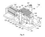
- FIG. 5 is a perspective view of the powered anvil 130.
- the components of the anvil 130 are arranged on a mounting plate 131 which is bolted to the underside of the main bed of the robot via mounting pillars 144, one of which is shown.
- the anvil 130 comprises a top plate 135 which is perforated with an array of holes 141 having diameters large enough to loosely receive pipette tips and arranged in a standard well plate grid so as to receive pipette tips loaded into a pipette tip tray.
- three tray clamps 139 are provided around the margin of the top plate. These move apart to a released position when a spigot 140, arranged to one side of the top plate 135 and extending above the plane of the top plate surface, is pushed down.
- a spring loaded mechanism connects the spigot 140 to the tray clamps 139.
- a pipette tip tray is loaded into the anvil by lowering the liquid handling head, with a tray gripped in its pincers, down onto the top plate 135, where the head itself depresses the spigot 140 opening up the tray clamps 139 for acceptance of the tray.
- the head is then raised allowing the spigot 140 to rise with it and thus the tray clamps 139 to move back inwards relative to the top plate 135, thereby clamping the tray in place.
- the top plate 135 is arranged spaced apart above a base plate 134, the two being slidably connected by vertically arranged posts 145, wherein the top plate 135 can be slid up and down the posts 145. Movement of the top plate 135 is driven by a pneumatic piston assembly comprising a cylinder unit 132 and piston 133.
- the cylinder unit 132 is double acting driven by two compressed air feed lines (not shown) and has two stable positions, extended (as illustrated) and retracted. Actuation of the piston 135 moves an elongate cam 142 along a rail 143.
- the cam 142 has a ramp (not visible) which engages with the underside of the top plate 135 to push it vertically upwards on the posts 145 when the piston 133 moves over a portion of its travel close to its extended position. Motion of the cam 142 also drives rotation of a pair of flippers 137 which act as clamping arms for a robot head.
- the flippers 137 are mounted on columns 136 that are rotatably mounted in the mounting plate 131. At their lower ends, the columns 136 are connected to inwardly directed lever arms 138 that are in engagement with a waisted portion of the elongate cam 142.
- anvil apparatus 130 is arranged in the robot as illustrated in Figure 4, with the piston assembly 132, 133 and base plate 134 below the level of the main bed surface. As already mentioned, this is achieved by bolting the anvil apparatus to the underside of the main bed of the robot via the mounting pillars 144.
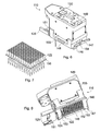
- Figures 6 and 8 are perspective views from different angles of a liquid handling head 110 for pipetting up to 250 ml per pipette.
- the head 110 includes clamping slots 148 arranged to receive the flippers 137 when the head is lowered onto the anvil with a loaded pipette tip tray already in the anvil, and when the flippers 137 are then rotated into the position illustrated in Figure 5 by motion of the cam.
- fitting pipette tips onto the head proceeds as follows.
- the clamping action of the flippers 137 serves to provide an abutment preventing upward motion of the head 110 in response to the upward driving force of the top plate 135 imparted by the ramped cam 142.
- the pipette tips 122 can be fitted to the cones 124 with a controlled force acting in a controlled direction, which provides for highly reliable liquid tight pipette tip attachment to the cones.
- the head 110 is provided with pincers 125 which are used to grip pipette tip trays.
- the pincers 125 are driven by a motor drive 151. Using the pincers 125 and the robot's x-, y- and z-positioners, the head 110 can be used to move pipette tip trays around the apparatus as required.
- the head 110 is also provided with jaws (not shown) for gripping well plates or other sample plates such as omni-trays Q-trays or petri dishes. The jaws are arranged on the opposite side of the head 110 to the pincers 125.
- the head 110 is provided with an array of pipette tip receiving cones 124, one of which is illustrated in Figure 8.
- the cones 124 are arranged in an array that is conformant to the well plate type being processed, which in this example is a 12 x 8 array for 96-well well plates.
- a single pipette tip 122 is also shown in Figure 8 for illustration purposes.
- Each cone 124 is as illustrated in Figure 3 with a central capillary leading to a reservoir formed by a barrel and piston, in which the piston is slidable up and down in the barrel to provide a syringing action.
- the reservoirs are located in the interior of the main body 155 of the head 110.
- the outer surfaces of the cones 124 are corrugated to assist pipette gripping.
- the cones 124 are made of resilient material to aid formation of a liquid tight seal between themselves and the pipette tips 122.
- the head 110 is secured to the z-positioner via a securing plate 149 on its upper side.
- the securing plate 149 also provides a host for an electrical contact pad 150 which mates with a corresponding contact pad on the z-positioner.
- the contact pad 150 provides the head 110 with electrical power feeds for driving the pincer motors, syringing pistons and other functions and also communication feed-throughs for providing communication lines from the main robot to the logic within the head.
- each head has a unique identifier so that the robot can interrogate the head to receive identification data and thus determine the head's identity, which will not only define the head's handling while installed, but also define its parking bay when the heads need to be exchanged or parked.
- the bottom side of the head 110 has a slotted plate 146 mounted by hinges 153, with the slots 152 being evident in Figure 8.
- the slot width is greater than the maximum outer diameter of the cones 124, but less than the maximum outer diameter of the pipette tips 122. Pipette tips 122 can be stripped from the cones 124, and thus the head 110, by hinging the slotted plate 146.
- the slotted plate 146 is actuated by a stripping arm 147 which is mounted on a pivot 154 and has one end that protrudes beyond the side of the main body of the head and another end that is situated above an edge flange of the slotted plate 146.
- the protruding end of the stripping arm is actuated when the head 110 is moved down over the waste chute 120 and encounters a stripping post, which pivots the stripping arm so that its other end pushes down on the flange of the slotted plate 146 causing hinging of the slotted plate.
- the pipette tips 22 are thus stripped off over the waste chute 120.
- FIG 7 is a perspective view of a pipette tip tray 156 loaded with pipette tips 122.
- Figure 7 is the same as Figure 2, but is reproduced to illustrate a pipette tip tray juxtaposed with a liquid handling head embodying the invention.
- the pipette tips 122 are loaded into trays to allow robotic handling.
- Each tray is a flat piece of stiff material, such as metal or plastic, with an array of through holes in a grid conforming to the desired well plate standard grid, the through holes having a diameter equal to part of the tapered neck portion of the pipette tips 122, so that pipette tips 122 seat in the through holes.
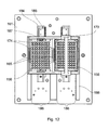
- Figures 9 to 12 show views of the pipette tip tray dispenser 160 in perspective, from the end, from the side and from above respectively.
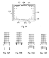
- Figure 13 is a detail side view of the lower end of a storage cassette 170 loaded with a stack of pipette tip trays 156 loaded with pipette tips 122.
- Figure 14 is a view from below of a storage cassette 170.
- the pipette tip tray dispenser 160 is designed to accommodate two pipette tip tray storage cassettes 170, one for large volume pipette tips (for pipetting up to 250 microliter) and one for small volume pipette tips (for pipetting up to 50 microliter). Only one storage cassette 170 is illustrated in order to reveal details of the other storage cassette docking area. The top level of loaded pipette tips 122 carried on a tray 156 within the cassette is also shown.
- Each storage cassette 170 is provided with a carrying handle 173 for ease of installation into and removal from the dispenser 160.
- the storage cassettes 170 stand sleeved in the upper part of the dispenser 160 without locking or latching.
- the interior of each storage cassette 170 forms a storage shaft 172 having an internal cross-section shaped and dimensioned to receive vertically stacked pipette tip trays loaded with pipette tips.
- the vertical stacking is such that each pipette tip tray above the lowest one is supported by the upper ends, i.e. the top rim surface, of the pipette tips loaded into the pipette tip tray immediately below.
- the storage shaft 172 is smooth in the vertical direction to allow the pipette tip trays to slide up and down.
- the lowest stacked pipette tip tray, and thus any other pipette tip trays stacked vertically above it, are retained in the storage shaft 172 by two pairs of mutually facing spring catches 171 which normally adopt a tray retention position, but can be forced outwards to a tray release position in which pipette tip trays are able to slide down the storage shaft past the catches 171. Tray dispensing is described in more detail further below, after a fuller description of the dispenser 160 has been given.
- the dispenser components are mounted to a main plate 161 which bolts to the top surface of the robot main bed 118.
- a housing 188 formed of two end plates, two side plates and a dividing plate between the side plates is arranged on the upper side of the main plate 161 and defines two generally rectangular apertures for receiving the storage cassettes 170 from above.
- Two tray dispensing channels are formed by the side plates and dividing plate which are spaced apart by slightly less than the tray width. Trays can be slid along the dispensing channels located in mutually facing L-section ledges 186 machined into the upper, inwardly facing corners of the side and dividing plates. A tray located in the ledges 186 is visible in the left-hand dispensing channel of Figure 12.
- Trays are driven along the dispensing channels away from the storage cassette docking area by a conveyor arrangement comprising a fixed base 184 and linearly movable slider 185 which has a dog 187 standing up near the rear end of the slider high enough to push a tray along the dispensing channel that is seated in the L-section ledges.
- a conveyor arrangement comprising a fixed base 184 and linearly movable slider 185 which has a dog 187 standing up near the rear end of the slider high enough to push a tray along the dispensing channel that is seated in the L-section ledges.
- the conveyor drive components are obscured in the perspective view from above of Figure 9, since they lie below the main plate 161, but are visible in the end and side views of Figures 10 and 11.
- the two sliders 185 can be moved back and forth in unison by a belt drive comprising two belts 181 which are driven from a common electric motor 180 through a succession of toothed gear wheels 182, 183.
- independent conveyor drives could be provided.
- driving the belt drive in one direction (clockwise in Figure 11) will cause the dog 187 to push a tray out of the storage cassette docking area to the head pick-up area (tray movement to the right in Figure 11).
- the drive direction is reversed (to counterclockwise in Figure 11), and the dog 187 moves back to the position shown in Figure 9 ready for pushing another tray along the dispensing channel.
- the sliding blades 165 are most clearly seen in Figures 10, 11 and 12.
- the sliding blade pairs 165 are spaced apart by a distance slightly less than the tray width.
- the interior of the lower ends of the storage cassettes is provided with side recesses 174 which allow space for the blades 165 to be moved up into the lower end of the storage cassette sufficiently high to outwardly displace the spring catches 171 and abut the lowest tray held in the storage cassette 170.
- the side recesses 174 into which the blades can be moved are most clearly evident in Figure 14 which is a view from below of a storage cassette 170.
- Figure 14 also shows corner recesses 175 in the inside of the cassette which are provided to avoid tray jamming.
- the actuation mechanism for raising and lowering the blade pairs 165 is now described.
- the blades of each pair are rigidly connected to each other by a rod 167.
- Each rod 167 is connected to a piston 166 arranged in a cylinder 162.
- the piston and cylinder pairs form pneumatic piston assemblies that are driven by compressed air lines (not shown) between an extended (upper) position and a retracted (lower) position.
- the upper edges of the blades 165 lie slightly below the level of the horizontal part of the L-section ledges 186.
- the upper edges of the blades 165 lie slightly above the level of the lower surface of a tray 156 supported on the spring catches 171.
- the pneumatic cylinders 162 are bolted hanging down from a cylinder mounting plate 163 which is in turn suspended below the main plate 161 by pillars 164.
- Figures 15A-D are highly schematic end views showing four steps in dispensing a pipette tip tray from the storage cassette. These are schematic versions of the same view as Figure 10. To highlight the principles of operation, only the spring catches are shown together with a number of vertically stacked trays filled with pipette tips and a blade pair.
- Figure 15A shows the starting position with a number of filled trays (six in the figure) loaded in the storage cassette, the lowest tray resting on the horizontal surfaces of the spring catches which thereby support the tray stack.
- the blade pair is in its lowest position with its driving piston retracted.
- Figure 15B shows a subsequent position in which the blade pair has been slid to its uppermost position, with the driving piston extended. In this position, the blades have laterally displaced the spring catches so as to be in contact with the edges of the lowest tray and thereby support the tray stack.
- Figure 15C shows a subsequent position in which the blade pair has been partially withdrawn taking the lowest tray with it.
- the spring catches move back into position, but only after the lowest tray has moved past them, thereby catching the next tray as illustrated and thus supporting the remainder of the tray stack.
- Figure 15D shows a subsequent position in which the blade pair is in its lowest position with its upper edges no longer in contact with the dispensed tray which is now resting in the dispensing channel on the L-shaped ledges which are schematically indicated ready for dispensing via the conveyor. After dispensing the tray, the apparatus has returned to the state of Figure 15A.
- Figure 16 is a side view of a storage cassette loading bay.
- the loading bay has a solid metal base 190 sufficiently heavy to provide stability on which four legs 192 stand in a rectangular arrangement.
- the legs 192 support a top 193 perforated with holes that match the holes in the pipette tip trays for which the loading bay is intended.
- a stack of pipette tip trays 156 with pipette tips 122 can be arranged on the top 193, a stack of four being shown in the figure.
- a stack of pipette tip trays can be conveniently inserted into an empty storage cassette by lifting the storage cassette over the loading bay, for example using its handle, and then lowering the storage cassette down onto the loading bay so that the trays push past the spring catches and into the storage shaft.
- the loading bay legs 192 have a length suitable for the loading, so that when the bottom of the storage cassette rests on the base 190, the plane of the loading bay top 193 is slightly above the plane of the horizontally extending part of the spring catches on which the lowest tray would normally bear.
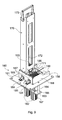
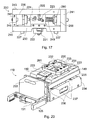
- Figure 17 is a side view of the head latching unit 220 that is attached to the z-positioner motor drive and serves to allow different heads to be loaded and unloaded.
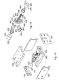
- Figure 18 is an exploded perspective view of the head latching mechanism of the head latching unit 220.
- Figure 19 is an exploded perspective view of the head latching unit 220 with the head latching mechanism of Figure 18 partly assembled.
- the head latching unit 220 comprises a housing made of top and bottom plates 243 and 240 and left and right end plates 242 and 241. Non-structural side plates 244 are also provided (omitted from Figure 17, but evident in Figure 19).
- the bottom plate 240 is provided on its lower side with locating stubs 227 to assist location of the head latching unit in corresponding holes in the heads.
- the latching mechanism is driven by a push-me-pull-you pneumatic piston assembly comprising a delatch driving piston 250 and a latch driving piston 260 with respective cylinders 226 and 266.
- the cylinders 226 and 266 are rotatably mounted by spigots 252 (see Figure 18) located in blocks 245 (see Figure 19) secured to the base plate 240 in a manner similar to a howitzer.
- the cylinders act on a knee joint 255 connecting to a floating upper joint 257 by an upper link 247.
- the knee joint 255 is also connected to a lower fixed joint 256 by a lower link 248.
- the fixed joint 256 is located in the side plates 246 (only one of which is shown in Figure 18) by a locating pin.
- the knee joint 255 is connected to both pistons 250, 260 by respective connectors 251 assisted by a locating pin 253.
- the knee joint 255 has a pin 253 running through it which fits into a pair of arcuate slots 223 in the side plates 246 retained by a pair of outside circlips 254.
- the floating upper joint 257 also has a pin 253 running through it which fits in a pair of vertical slots 225 in the side plates 246 retained by a pair of outside circlips 254.
- the floating upper joint pin also pivotally mounts a latching arm 222.
- the latching arm 222 extends obliquely down to a non-jointed bend 258 with a hole through which a further pin 253 passes which is retained by outside circlips 254 and fits into an L-shaped slot 224 in the side plates 246.
- the latching arm 22 extends vertically down and then at right angles thereto extends further to form a latch support which bears a latch 221.
- FIG 20 is a perspective view of a liquid handling head 110 showing parts used to secure the head to the head securing unit.
- the liquid handling head illustrated is one for pipetting volumes of 1-50 microliters per pipette, in contrast to the larger volume pipetting provided by the liquid handling head illustrated in Figures 6 and 8.
- the latching components of all heads will be similar.
- Figure 20 also shows upper and lower subassemblies 235 and 234 respectively.
- the lower subassembly 234 has ramps 236 on its upper surface on which ride wheels 237 that are carried by the upper subassembly 235. Riding up and down the ramps changes the separation between the subassemblies 235 and 234 and is the movement that provides the syringing action, the reservoir pistons being carried by the upper subassembly 235 and the reservoir cylinders being part of the lower subassembly 234.
- the motion is driven by an electric motor carried in the head.
- FIG. 17-19 illustrate the mechanism in the latched position. In view of this, movement of the mechanism from the latched position to the delatched position is described. This is the movement that would be performed when a head had been returned to its parking bay and was to be released by the head latching unit to allow the z-positioner with head latching unit to be moved away to pick up a different head.
- the delatching piston 250 is pneumatically actuated by compressed air through a feed line (not shown) which pushes the knee joint 255 to the right (as viewed in the figures) which pushes the pin around the arcuate slot 223.
- the non-jointed bend 258 is also forced vertically down guided by the upright part of the L-shaped slot 224.
- the latch 221 is being moved vertically down, allowing it to become free of the head's latch 230 (assuming the head 110 is supported in its parking bay).
- the latching arm 222 is forced to rotate by the pin through the non-jointed bend 258 being confined to move in the base of the L-shaped slot until it abuts the end of the base section of the L-shaped slot.
- the mechanism is now in the delatched position, with the knee joint 255 at its maximum bend and the latching arm 222 at is maximum swing angle away from vertical, swung into a space 261 provided within the plate 231.
- the latching arm 222 has swung away sufficiently to allow the latching unit 220 to be lifted away from the head 110 by a simple vertical motion of the z-positioner. It will now be appreciated why the piston assemblies are pivotally mounted, namely to accommodate movement of the pins in the slots 223, 224 and 225.
- Motion from the delatched to the latched position proceeds approximately in the reverse sequence. It is initiated by actuation of the latching piston 260 which acts on the knee joint 255 to straighten it out.
- the reverse sequence of slot motion is performed in relation to the latch-to-delatch motion with the latching arm 222 being forced to move vertically upward in the L-shaped slot 224 when the pin through the non-jointed bend 258 reaches the corner of the L-shaped slot 224.
- the design allows a high amount of clamping force to be exerted, with the head's latch 230 being squeezed between the latching unit's latch 221 and the bottom of the lower link 248. This feature provides a highly secure latching of the head.
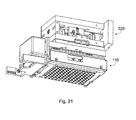
- Figure 21 shows the low volume liquid handling head 110 attached to the head securing unit 220 with the latching mechanism in the latched position described above.
Abstract
Description
- The invention relates to liquid handling robots for well plates which are used in biochemistry and microbiology for processing large numbers of samples in parallel.
- Figure 1 is a perspective view of a liquid handling robot according to the prior art. The robot comprises a
movable head 10 that is used for liquid handling and also has a mechanical manipulation capability. Thehead 10 is movable in three orthogonal axes, x, y and z, withrespective motor positioners control unit 15. Thehead 10 may also incorporates a camera (not shown) used to perform machine vision functions, such as bar code reading of well plates. Thehead 10 is movable over amain bed 18 of the apparatus on which well plates and other biological sample containers, such as Q-trays, petri dishes and omni-trays, can be arranged, usually within anexperimental area 19. Awaste chute 20 is incorporated in themain bed 18 and is flanked by strippingarm posts 21, the purpose of which is described below. - For mechanical manipulation, the
head 10 is provided withpincers 25 which are used to grip pipette tip trays. Using thepincers 25 and thepositioners head 10 can be used to move pipette tip trays around the apparatus as required. Thehead 10 is also provided withjaws 26 arranged in the horizontal plane for gripping well plates or other sample plates such as omni-trays Q-trays or petri dishes. - Figure 2 is a perspective view of a pipette tip tray 34 loaded with
pipette tips 22. Thepipette tips 22 are loaded into trays to allow robotic handling. Each tray is a flat piece of stiff material, such as metal or plastic, with an array of through holes in a grid conforming to the desired well plate standard grid, the through holes having a diameter equal to part of the tapered neck portion of thepipette tips 22, so thatpipette tips 22 seat in the through holes. - For liquid handling, the head is provided with an array of pipette
tip receiving cones 24 with the array being conformant to the well plate type being processed, for example a 12 x 8 array for 96-well well plates. - Figure 3 shows a single
pipette tip cone 24 together with an upper end of apipette tip 22. Eachcone 24 has a central capillary leading to a reservoir formed by a barrel and piston, in which the piston is slidable up and down in the barrel to provide a syringing action. The outer surfaces of thecones 24 are corrugated to assist pipette gripping. The cones are made of resilient material to aid formation of a liquid tight seal between themselves and thepipette tips 22 they are designed to receive. - Referring back to Figure 1, arranged on the
main bed 18 of the apparatus there can be seen a pipettetip tray anvil 32. Theanvil 32 is a plate with an array of through holes in a grid conforming to one of the well plate standard grids, the through holes having a diameter slightly larger than the outer diameter of the widest part of thepipette tips 22. - A number of trays 34 loaded with
unused pipette tips 22 are held in a shelvedstorage rack 36, sometimes referred to as a "hotel" in the art, with each tray arranged on one shelf and vertically adjacent shelves spaced far enough apart to avoid the pipette tips fouling each other when they are slid in and out of the shelves. In the schematic drawing, the hotel is illustrated as having three racks, each with three shelves. A greater number of shelves would usually be provided in practice. - The action of
loading pipette tips 22 onto theliquid handling head 10 is now described. Thehead 10 is moved over to the pipette tiptray storage rack 36 and, using thepincers 25, one of the pipette tip trays 34 is taken out and placed on theanvil 32. Thehead 10 is then moved so that the array ofcones 24 is aligned above the array ofpipette tips 22. Using the lead screw motor drive of the z-positioner 16, thehead 10 is then driven down so that the (male)cones 24 mate with the (female) upper apertures of thepipette tips 22, theanvil 32 acting as an abutment surface to allow thepipette tips 22 to be pushed onto thecones 24. Thehead 10 is then raised away from theanvil 32 using the z-positioner 16 with each of thecones 24 now loaded with apipette tip 22 ready for liquid handling. - Once the desired pipetting action has been completed, the pipette tips, which are disposable items, can be removed from the head as now described. The
head 10 includes a slotted plate (not shown), immediately above thecones 24 with the slots having a width greater than the maximum outer diameter of the cones and less than the maximum outer diameter of thepipette tips 22. The slotted plate is hinged to the main body of theliquid handling head 10. The hinging action allows ejection ofpipette tips 22 from thecones 24 on which they are seated. The hinged slotted plate is actuated by a lever acting on the slotted plate being pushed onto thestripping posts 21 as thehead 10 is driven down over thewaste chute 20. The pipette tips are thus stripped off over thewaste chute 20. - Some undesirable aspects of this design have been identified.
- The anvil-based pipette tip loading process is not always reliable. The loaded pipette tips can on occasion fall off their cones, especially during syringing out of the liquid reservoir. If this happens, the resultant spillage can destroy the integrity of a whole well plate, which may contain valuable reagents and contain samples obtained from several processing steps already performed.
- Manual loading of the pipette tip trays into the shelved storage rack is a fiddly, time consuming exercise, which needs to be performed with care in view of the fact that the pipette tips may be fragile and are held loose in their trays.
- The liquid handling robot is not capable of performing other actions, such as gridding or picking, which necessitates transfer of the well plates to another machine if these actions need to be performed before or after the liquid handling actions. Each such transfer, carries a contamination risk, and is also inconvenient.
- According to the invention there is provided an anvil apparatus for a liquid handling robot comprising: an apertured plate for receiving an array of pipette tips; a clamping arrangement for holding down a liquid handling head of the liquid handling robot above the apertured plate; and a drive for forcing the apertured plate and the liquid handling head together while the liquid handling head is held down by the clamping arrangement in order to push pipette tips onto the liquid handling head.
- The powered anvil of the invention is found to provide enhanced reliability, which is attributed to the fact that a controlled smooth action can be provided for pressing the pipette tips onto the liquid handling head. Moreover, by first clamping the liquid handling head to the anvil, a well defined driving force can be applied with a separate drive so that the driving force can be optimized for the pipette fitting action.
- This contrasts with the prior art approach of using the head's own vertical motor drive to force the head down onto the pipette tips. The prior art approach is believed to cause difficulties, since the motor drive of the liquid handling head is principally designed as a positioning device, and is not suited to being used effectively as a ram which may even damage the motor drive and compromise its linearity. The vertical positioner's motor is neither designed to be driven against an immovable object, nor to deliver a controlled reproducible ramming force when it is driven against an immovable object. In particular, it is believed that it is important to apply the force exactly in line with the cones, i.e. perpendicular to the anvil plate surface, for reliable pipette tip loading, and this is not ensured by using the head's vertical positioner drive, since its drive axis is laterally offset from cone array, so a slight hinging, bending or skewing effect may be occurring at the instant of tip loading.
- The drive may comprise a jack arranged to push the apertured plate upwards from below. The jack can be implemented with a pneumatically actuated piston assembly. Many other solutions could also be adopted, for example based on motor drives.
- The clamping arrangement may comprise movable arms that are actuatable between clamping and free positions to clamp and release the liquid handling head.
- The array may conveniently conform to a well plate standard spacing, for example for a well plate having 96 wells or 384 wells. In this regard, it is to be understood that the pipette tip array need not be as large as a whole well plate array. For example, the pipette tip array may be a 4 x 6 array, covering a quarter of a 96-well well plate which is made up of an 8 x 12 array of wells.
- According to the invention there is further provided a liquid handling robot comprising: an anvil apparatus according to the first aspect of the invention; and a liquid handling head having an array of cones for receiving pipette tips shaped to mate with the clamping arrangement of the anvil apparatus.
- According to the invention there is provided a storage cassette for loaded pipette tip trays comprising: a storage shaft having an internal cross-section shaped and dimensioned to receive vertically stacked pipette tip trays loaded with pipette tips and to allow the pipette tip trays to slide up and down the storage shaft; and a tray retaining mechanism having a retention position in which a lowest one of the pipette tip trays, and thus pipette tip trays vertically stacked above it, are retained in the storage cassette, and a release position in which the pipette tip trays are free to slide down the storage shaft past the tray retaining mechanism.
- The tray retaining mechanism may include spring biasing which can be urged into the release position by an actuating force, but otherwise adopts the retention position. Alternatively, a variety of other movable retaining mechanisms could be used. For example, sliding catches drivable by motors between the two positions.
- According to the invention there is further provided a pipette tip tray dispenser comprising: a storage cassette according to the invention; and a base unit on which the storage cassette is mountable, the base unit comprising a vertically movable pipette tip tray carrier that can be raised to support the lowest pipette tip tray held in the storage cassette and lowered to carry the lowest pipette tip tray out of the storage shaft beyond the tray retaining mechanism.
- The carrier is preferably arranged so that its upward motion to support the lowest pipette tip tray held in the storage cassette moves the tray retaining mechanism from its retention position to its release position and its downward motion allows passage of the lowest pipette tip tray beyond the tray retaining mechanism before the tray retaining mechanism returns to its retention position, thereby allowing the lowest pipette tip tray to be dispensed.
- The carrier may advantageously lower the dispensed lowest pipette tip tray onto a conveyor for moving the pipette tip tray away from the storage cassette for subsequent use.
- In an embodiment of the invention, the storage cassette is detachably arranged on the base unit.
- It is noted that a strength of the pipette tip tray dispenser and storage cassette design is that the dispensing channels and storage cassettes can be used for different pipette tip sizes without any redesign. For example, if two dispensing channels are provided, one can be used with a storage cassette loaded with large volume pipette tips and the other with a storage cassette loaded with small volume pipette tips. A storage cassette loaded with small volume pipette tips installed in one dispensing channel could be swapped with a storage cassette loaded with large volume pipette tips without any reconfiguration of the mechanical components being necessary. The robot control system would however need to be informed.
- According to the invention there is further provided a liquid handling robot comprising a pipette tip tray dispenser according to the invention. The liquid handling robot may further comprise a head with a manipulator for removing pipette tip trays from the pipette tip tray dispenser.
- According to the invention there is provided a robot for handling biological sample containers, comprising: a head for carrying out processes on biological sample containers; a positioning apparatus for moving the head around the robot; and a parking station for parking the head, wherein the head is connected to the positioning apparatus by an attachment mechanism drivable between a clamped state, in which the head is secured to the positioning apparatus, and a released state, in which the head can be detached from the positioning apparatus and deposited in the park station.
- The park station preferably comprises a plurality of parking bays, each for parking one head. This allows different types of head to be stored ready for action, and also spare heads of the same type in case the head being used suffers a failure.
- The robot will typically be provided with multiple heads, for example two or more liquid handling heads, a mixture of liquid handling and pin heads, or two or more pin heads, thereby providing a flexible multi-purpose robot, capable of carrying out a variety of liquid handling, spotting, gridding and colony picking tasks.
- In an embodiment of the invention, the attachment mechanism comprises a piston assembly arranged to actuate a knee joint connected to a latch, the knee joint adopting a bent position in the released state and straightened position in the clamped state. The piston assembly may advantageously include two piston cylinder units arranged in a push-me-pull-you configuration either side of the knee joint.
- The attachment mechanism may include a communication feed-through, and each head resident logic that allows the robot through the communication feed-through to receive identification data from any head that is attached to the positioning apparatus.
- It will be understood that the powered anvil, pipette tip tray dispenser and automated head attachment can be advantageously combined in a single liquid handling robot. In particular the combination of automated pipette tip tray dispenser and powered anvil is a powerful combination which allows for rapid and reliable liquid handling of well plates using disposable pipette tips. Liquid handling is further enhanced by the ability to swap between multiple liquid handling heads in a fully automated fashion, the heads being specialized to perform different tasks. For example, different liquid handling heads may be provided for large and small volume pipette tips, and the pipette tip tray dispenser can be loaded with two storage cassettes, one carrying large volume pipette tips and the other low volume pipette tips which are then independently dispensable through separate dispensing channels. In addition, the ability to be able to integrate picking or gridding functions within the liquid handling processes that is made possible by the automated head swapping capability opens up a whole range of new applications possibilities which would hitherto have necessitated using different robots and moving samples manually between them.
- The various possible combinations of any two of the powered anvil, pipette tip tray dispenser and automated head attachment, or the combination of all three, thus provide new and powerful functionalities additional to the independent functionalities of each item.
- For a better understanding of the invention and to show how the same may be carried into effect reference is now made by way of example to the accompanying drawings in which:
- Figure 1 is a perspective view of a liquid handling robot according to the prior art;
- Figure 2 shows a pipette tip tray loaded with pipette tips;
- Figure 3 shows a pipette tip cone and upper end of a pipette tip;
- Figure 4 is a perspective view of a liquid handling robot according to an embodiment of the invention comprising an automated pipette tip tray dispenser, powered anvil, and automated head swapping components;
- Figure 5 is a perspective view of the powered anvil;
- Figure 6 is a perspective view of a liquid handling head for pipetting up to 250 ml per pipette;
- Figure 7 is a perspective view of a pipette tip tray loaded with pipette tips;
- Figure 8 is a further perspective view of the liquid handling head from a different perspective than Figure 6 showing the underside of the liquid handling head;
- Figure 9 is a perspective view of the pipette tip tray dispenser;
- Figure 10 is an end view of the pipette tip tray dispenser;
- Figure 11 is a side view of the pipette tip tray dispenser;
- Figure 12 is a plan view of the pipette tip tray dispenser;
- Figure 13 is a close-up side view of a storage cassette loaded with pipette tip trays;
- Figure 14 is a view from below of a storage cassette loaded with pipette tip trays;
- Figures 15A-D are schematic end views showing four steps in dispensing a pipette tip tray from a storage cassette;
- Figure 16 is a side view of a storage cassette loading bay;
- Figure 17 is a side view of the head latching unit that is attached to the z-positioner motor drive;
- Figure 18 is an exploded perspective view of the head latching mechanism of the head latching unit;
- Figure 19 is an exploded perspective view of the head latching unit with the head latching mechanism of Figure 18 partly assembled;
- Figure 20 is a perspective view of a liquid handling head showing parts used to secure the head to the head securing unit; and
- Figure 21 shows the head attached to the head securing unit.
- Figure 4 is a perspective view of a liquid handling robot according to an embodiment of the invention. The robot comprises a
movable head 110 that is used for liquid handling and also has a mechanical manipulation capability. Thehead 110 is movable in three orthogonal axes, x, y and z, withrespective motor positioners head 110 may also incorporates a camera (not shown) used to perform machine vision functions, such as bar code reading of well plates. Thehead 110 is movable over amain bed 118 of the apparatus on which well plates and other biological sample containers, such as Q-trays, petri dishes and omni-trays, can be arranged as well as other items such asvacuum manifolds 102 andshakers 104 for processing well plates. Adjacent to thevacuum manifolds 102 andshakers 104 there is ageneral processing area 105 where well plates, liquid reservoirs and other containers can be arranged for conducting experiments. The main bed of the apparatus is supported at a convenient height on atable frame 106. Awaste chute 120 is incorporated in themain bed 118 and is flanked by stripping arm posts (not visible). Situated on the far side of themain bed 118 there is a wellplate storage rack 108 with four shelf stacks arranged side by side. A slidable cover for the well plate storage rack is also illustrated. Well plates can be taken out of thestorage rack 108 by thehead 110 using gripping jaws (not visible). - The robot has a powered pipette
tip tray anvil 130 which is described in detail further below with reference to Figures 5 to 8. - The robot also has an automated pipette
tip tray dispenser 160 which is designed to accommodate two pipette tiptray storage cassettes 170, one for large volume pipette tips (for pipetting up to 250 microliter) and one for small volume pipette tips (for pipetting up to 50 microliter). Only one fittedstorage cassette 170 is illustrated. Thestorage cassettes 170 can be installed and removed from thedispenser 160 by hand. The automated pipettetip tray dispenser 160 and thestorage cassettes 170 are described in detail further below with reference to Figures 9 to 16. - The robot has the capability of automatically changing between different heads. The available heads for the particular robot configuration can be parked in
bays 210 within apark station 200. Twoparking bays 210 are shown in the illustratedpark station 200. These are for two different liquid handling heads, a large volume item (up to 250 microliters per pipette) and a small volume item (1-50 microliters per pipette). In other embodiments, three, four or more bays could be provided. As well as liquid handling heads, pin heads for colony picking or spotting or gridding could be provided depending on the robot configuration that is desired. The head swapping functionality and associated equipment is described in detail further below with reference to Figures 17 to 19. - Figure 5 is a perspective view of the
powered anvil 130. The components of theanvil 130 are arranged on a mountingplate 131 which is bolted to the underside of the main bed of the robot via mountingpillars 144, one of which is shown. Theanvil 130 comprises atop plate 135 which is perforated with an array ofholes 141 having diameters large enough to loosely receive pipette tips and arranged in a standard well plate grid so as to receive pipette tips loaded into a pipette tip tray. Around the margin of the top plate, three tray clamps 139 are provided. These move apart to a released position when aspigot 140, arranged to one side of thetop plate 135 and extending above the plane of the top plate surface, is pushed down. A spring loaded mechanism connects thespigot 140 to the tray clamps 139. In use, a pipette tip tray is loaded into the anvil by lowering the liquid handling head, with a tray gripped in its pincers, down onto thetop plate 135, where the head itself depresses thespigot 140 opening up the tray clamps 139 for acceptance of the tray. The head is then raised allowing thespigot 140 to rise with it and thus the tray clamps 139 to move back inwards relative to thetop plate 135, thereby clamping the tray in place. - The
top plate 135 is arranged spaced apart above abase plate 134, the two being slidably connected by vertically arrangedposts 145, wherein thetop plate 135 can be slid up and down theposts 145. Movement of thetop plate 135 is driven by a pneumatic piston assembly comprising acylinder unit 132 andpiston 133. Thecylinder unit 132 is double acting driven by two compressed air feed lines (not shown) and has two stable positions, extended (as illustrated) and retracted. Actuation of thepiston 135 moves anelongate cam 142 along arail 143. Thecam 142 has a ramp (not visible) which engages with the underside of thetop plate 135 to push it vertically upwards on theposts 145 when thepiston 133 moves over a portion of its travel close to its extended position. Motion of thecam 142 also drives rotation of a pair offlippers 137 which act as clamping arms for a robot head. Theflippers 137 are mounted oncolumns 136 that are rotatably mounted in the mountingplate 131. At their lower ends, thecolumns 136 are connected to inwardly directedlever arms 138 that are in engagement with a waisted portion of theelongate cam 142. Motion of theelongate cam 142 along a portion of the piston's travel, that is closer to the retracted position than the first-mentioned portion of travel, engages one end of the cam's waisted portion with thelever arms 138 to move the latter, thereby rotating thecolumns 136 and moving theflippers 137. - It will thus be understood that motion of the piston from its retracted position to its extended position initially causes the
flippers 137 to move around from an alignment generally parallel to the piston motion direction, to an inwardly pointing alignment as illustrated in Figure 5, and subsequently causes thetop plate 135 to be driven upwards. The significance of these movements is be discussed further below. - Finally in respect of Figure 5, it is noted that the
anvil apparatus 130 is arranged in the robot as illustrated in Figure 4, with thepiston assembly base plate 134 below the level of the main bed surface. As already mentioned, this is achieved by bolting the anvil apparatus to the underside of the main bed of the robot via the mountingpillars 144. - Figures 6 and 8 are perspective views from different angles of a
liquid handling head 110 for pipetting up to 250 ml per pipette. Thehead 110 includes clampingslots 148 arranged to receive theflippers 137 when the head is lowered onto the anvil with a loaded pipette tip tray already in the anvil, and when theflippers 137 are then rotated into the position illustrated in Figure 5 by motion of the cam. In use, fitting pipette tips onto the head proceeds as follows. - 1. A pipette tip tray loaded with pipette tips is placed onto the
anvil top plate 135 in the manner described further above. - 2. The head is lowered down onto the
anvil top plate 135 with thecones 124 aligned with thepipette tips 122 and loosely fitted therein. - 3. The
piston assembly piston 133 from its retracted position to its extended position which first rotates theflippers 137 into the clampingslots 148 to hold down the head, and second jacks theanvil top plate 135 upwards to ram the upper ends of thepipette tips 122 into the 124 cones. - Here it will be understood that the clamping action of the
flippers 137 serves to provide an abutment preventing upward motion of thehead 110 in response to the upward driving force of thetop plate 135 imparted by the rampedcam 142. In this way, thepipette tips 122 can be fitted to thecones 124 with a controlled force acting in a controlled direction, which provides for highly reliable liquid tight pipette tip attachment to the cones. - Other parts of the
head 110 are now described. - The
head 110 is provided withpincers 125 which are used to grip pipette tip trays. Thepincers 125 are driven by amotor drive 151. Using thepincers 125 and the robot's x-, y- and z-positioners, thehead 110 can be used to move pipette tip trays around the apparatus as required. Thehead 110 is also provided with jaws (not shown) for gripping well plates or other sample plates such as omni-trays Q-trays or petri dishes. The jaws are arranged on the opposite side of thehead 110 to thepincers 125. - The
head 110 is provided with an array of pipettetip receiving cones 124, one of which is illustrated in Figure 8. Thecones 124 are arranged in an array that is conformant to the well plate type being processed, which in this example is a 12 x 8 array for 96-well well plates. Asingle pipette tip 122 is also shown in Figure 8 for illustration purposes. - Each
cone 124 is as illustrated in Figure 3 with a central capillary leading to a reservoir formed by a barrel and piston, in which the piston is slidable up and down in the barrel to provide a syringing action. The reservoirs are located in the interior of themain body 155 of thehead 110. The outer surfaces of thecones 124 are corrugated to assist pipette gripping. Thecones 124 are made of resilient material to aid formation of a liquid tight seal between themselves and thepipette tips 122. Thehead 110 is secured to the z-positioner via a securingplate 149 on its upper side. The securingplate 149 also provides a host for anelectrical contact pad 150 which mates with a corresponding contact pad on the z-positioner. Thecontact pad 150 provides thehead 110 with electrical power feeds for driving the pincer motors, syringing pistons and other functions and also communication feed-throughs for providing communication lines from the main robot to the logic within the head. For example each head has a unique identifier so that the robot can interrogate the head to receive identification data and thus determine the head's identity, which will not only define the head's handling while installed, but also define its parking bay when the heads need to be exchanged or parked. - The bottom side of the
head 110 has a slottedplate 146 mounted byhinges 153, with theslots 152 being evident in Figure 8. The slot width is greater than the maximum outer diameter of thecones 124, but less than the maximum outer diameter of thepipette tips 122.Pipette tips 122 can be stripped from thecones 124, and thus thehead 110, by hinging the slottedplate 146. The slottedplate 146 is actuated by a strippingarm 147 which is mounted on apivot 154 and has one end that protrudes beyond the side of the main body of the head and another end that is situated above an edge flange of the slottedplate 146. In use, the protruding end of the stripping arm is actuated when thehead 110 is moved down over thewaste chute 120 and encounters a stripping post, which pivots the stripping arm so that its other end pushes down on the flange of the slottedplate 146 causing hinging of the slotted plate. Thepipette tips 22 are thus stripped off over thewaste chute 120. - Figure 7 is a perspective view of a
pipette tip tray 156 loaded withpipette tips 122. (Figure 7 is the same as Figure 2, but is reproduced to illustrate a pipette tip tray juxtaposed with a liquid handling head embodying the invention.) Thepipette tips 122 are loaded into trays to allow robotic handling. Each tray is a flat piece of stiff material, such as metal or plastic, with an array of through holes in a grid conforming to the desired well plate standard grid, the through holes having a diameter equal to part of the tapered neck portion of thepipette tips 122, so thatpipette tips 122 seat in the through holes. - Figures 9 to 12 show views of the pipette
tip tray dispenser 160 in perspective, from the end, from the side and from above respectively. - Figure 13 is a detail side view of the lower end of a
storage cassette 170 loaded with a stack ofpipette tip trays 156 loaded withpipette tips 122. - Figure 14 is a view from below of a
storage cassette 170. - The pipette
tip tray dispenser 160 is designed to accommodate two pipette tiptray storage cassettes 170, one for large volume pipette tips (for pipetting up to 250 microliter) and one for small volume pipette tips (for pipetting up to 50 microliter). Only onestorage cassette 170 is illustrated in order to reveal details of the other storage cassette docking area. The top level of loadedpipette tips 122 carried on atray 156 within the cassette is also shown. - Each
storage cassette 170 is provided with a carryinghandle 173 for ease of installation into and removal from thedispenser 160. Thestorage cassettes 170 stand sleeved in the upper part of thedispenser 160 without locking or latching. The interior of eachstorage cassette 170 forms astorage shaft 172 having an internal cross-section shaped and dimensioned to receive vertically stacked pipette tip trays loaded with pipette tips. The vertical stacking is such that each pipette tip tray above the lowest one is supported by the upper ends, i.e. the top rim surface, of the pipette tips loaded into the pipette tip tray immediately below. In this stacking position, the lower ends of the pipette tips from each tray (apart from the lowest one) extend into the upper apertures of the pipette tips carried by the tray immediately below. Thestorage shaft 172 is smooth in the vertical direction to allow the pipette tip trays to slide up and down. The lowest stacked pipette tip tray, and thus any other pipette tip trays stacked vertically above it, are retained in thestorage shaft 172 by two pairs of mutually facing spring catches 171 which normally adopt a tray retention position, but can be forced outwards to a tray release position in which pipette tip trays are able to slide down the storage shaft past thecatches 171. Tray dispensing is described in more detail further below, after a fuller description of thedispenser 160 has been given. - The dispenser components are mounted to a
main plate 161 which bolts to the top surface of the robotmain bed 118. Ahousing 188 formed of two end plates, two side plates and a dividing plate between the side plates is arranged on the upper side of themain plate 161 and defines two generally rectangular apertures for receiving thestorage cassettes 170 from above. Two tray dispensing channels are formed by the side plates and dividing plate which are spaced apart by slightly less than the tray width. Trays can be slid along the dispensing channels located in mutually facing L-section ledges 186 machined into the upper, inwardly facing corners of the side and dividing plates. A tray located in theledges 186 is visible in the left-hand dispensing channel of Figure 12. Trays are driven along the dispensing channels away from the storage cassette docking area by a conveyor arrangement comprising a fixedbase 184 and linearlymovable slider 185 which has adog 187 standing up near the rear end of the slider high enough to push a tray along the dispensing channel that is seated in the L-section ledges. When theslider 185 is fully retracted (as in Figure 9 for example), thedog 187 is positioned sufficiently close to the rear end of the slider so that it does not foul a tray being dispensed from thestorage cassette 170. - The conveyor drive components are obscured in the perspective view from above of Figure 9, since they lie below the
main plate 161, but are visible in the end and side views of Figures 10 and 11. The twosliders 185 can be moved back and forth in unison by a belt drive comprising twobelts 181 which are driven from a commonelectric motor 180 through a succession oftoothed gear wheels dog 187 to push a tray out of the storage cassette docking area to the head pick-up area (tray movement to the right in Figure 11). Once thedog 187 has reached its end position, the drive direction is reversed (to counterclockwise in Figure 11), and thedog 187 moves back to the position shown in Figure 9 ready for pushing another tray along the dispensing channel. - Also arranged on the underside of the
main plate 161 are components for driving two pairs of slidingblades 165 that actuate the spring catches 171 ofstorage cassettes 170 sleeved in thehousing 188. The slidingblades 165 are most clearly seen in Figures 10, 11 and 12. The sliding blade pairs 165 are spaced apart by a distance slightly less than the tray width. The interior of the lower ends of the storage cassettes is provided withside recesses 174 which allow space for theblades 165 to be moved up into the lower end of the storage cassette sufficiently high to outwardly displace the spring catches 171 and abut the lowest tray held in thestorage cassette 170. The side recesses 174 into which the blades can be moved are most clearly evident in Figure 14 which is a view from below of astorage cassette 170. Figure 14 also shows corner recesses 175 in the inside of the cassette which are provided to avoid tray jamming. - The actuation mechanism for raising and lowering the blade pairs 165 is now described. The blades of each pair are rigidly connected to each other by a
rod 167. Eachrod 167 is connected to apiston 166 arranged in acylinder 162. The piston and cylinder pairs form pneumatic piston assemblies that are driven by compressed air lines (not shown) between an extended (upper) position and a retracted (lower) position. In the retracted position (the one illustrated), the upper edges of theblades 165 lie slightly below the level of the horizontal part of the L-section ledges 186. In the extended position, the upper edges of theblades 165 lie slightly above the level of the lower surface of atray 156 supported on the spring catches 171. Thepneumatic cylinders 162 are bolted hanging down from acylinder mounting plate 163 which is in turn suspended below themain plate 161 bypillars 164. - Figures 15A-D are highly schematic end views showing four steps in dispensing a pipette tip tray from the storage cassette. These are schematic versions of the same view as Figure 10. To highlight the principles of operation, only the spring catches are shown together with a number of vertically stacked trays filled with pipette tips and a blade pair.
- Figure 15A shows the starting position with a number of filled trays (six in the figure) loaded in the storage cassette, the lowest tray resting on the horizontal surfaces of the spring catches which thereby support the tray stack. The blade pair is in its lowest position with its driving piston retracted.
- Figure 15B shows a subsequent position in which the blade pair has been slid to its uppermost position, with the driving piston extended. In this position, the blades have laterally displaced the spring catches so as to be in contact with the edges of the lowest tray and thereby support the tray stack.
- Figure 15C shows a subsequent position in which the blade pair has been partially withdrawn taking the lowest tray with it. As the blade pair lowers from the uppermost position as shown in Figure 15B, the spring catches move back into position, but only after the lowest tray has moved past them, thereby catching the next tray as illustrated and thus supporting the remainder of the tray stack.
- Figure 15D shows a subsequent position in which the blade pair is in its lowest position with its upper edges no longer in contact with the dispensed tray which is now resting in the dispensing channel on the L-shaped ledges which are schematically indicated ready for dispensing via the conveyor. After dispensing the tray, the apparatus has returned to the state of Figure 15A.
- Figure 16 is a side view of a storage cassette loading bay. The loading bay has a
solid metal base 190 sufficiently heavy to provide stability on which fourlegs 192 stand in a rectangular arrangement. Thelegs 192 support a top 193 perforated with holes that match the holes in the pipette tip trays for which the loading bay is intended. A stack ofpipette tip trays 156 withpipette tips 122 can be arranged on the top 193, a stack of four being shown in the figure. A stack of pipette tip trays can be conveniently inserted into an empty storage cassette by lifting the storage cassette over the loading bay, for example using its handle, and then lowering the storage cassette down onto the loading bay so that the trays push past the spring catches and into the storage shaft. Theloading bay legs 192 have a length suitable for the loading, so that when the bottom of the storage cassette rests on thebase 190, the plane of theloading bay top 193 is slightly above the plane of the horizontally extending part of the spring catches on which the lowest tray would normally bear. - Figure 17 is a side view of the
head latching unit 220 that is attached to the z-positioner motor drive and serves to allow different heads to be loaded and unloaded. - Figure 18 is an exploded perspective view of the head latching mechanism of the
head latching unit 220. - Figure 19 is an exploded perspective view of the
head latching unit 220 with the head latching mechanism of Figure 18 partly assembled. - The
head latching unit 220 comprises a housing made of top andbottom plates right end plates Non-structural side plates 244 are also provided (omitted from Figure 17, but evident in Figure 19). Thebottom plate 240 is provided on its lower side with locatingstubs 227 to assist location of the head latching unit in corresponding holes in the heads. - The latching mechanism is driven by a push-me-pull-you pneumatic piston assembly comprising a
delatch driving piston 250 and alatch driving piston 260 withrespective cylinders cylinders base plate 240 in a manner similar to a howitzer. - The cylinders act on a knee joint 255 connecting to a floating upper joint 257 by an
upper link 247. The knee joint 255 is also connected to a lower fixed joint 256 by alower link 248. The fixed joint 256 is located in the side plates 246 (only one of which is shown in Figure 18) by a locating pin. The knee joint 255 is connected to bothpistons respective connectors 251 assisted by a locatingpin 253. The knee joint 255 has apin 253 running through it which fits into a pair ofarcuate slots 223 in theside plates 246 retained by a pair ofoutside circlips 254. The floating upper joint 257 also has apin 253 running through it which fits in a pair ofvertical slots 225 in theside plates 246 retained by a pair ofoutside circlips 254. The floating upper joint pin also pivotally mounts alatching arm 222. The latchingarm 222 extends obliquely down to anon-jointed bend 258 with a hole through which afurther pin 253 passes which is retained byoutside circlips 254 and fits into an L-shapedslot 224 in theside plates 246. After thenon-jointed bend 258, the latchingarm 22 extends vertically down and then at right angles thereto extends further to form a latch support which bears alatch 221. - Before describing the latching action by which heads are attached to and detached from the latching
unit 220, the latching parts of the heads are first described. - Figure 20 is a perspective view of a
liquid handling head 110 showing parts used to secure the head to the head securing unit. For completeness, it is noted that the liquid handling head illustrated is one for pipetting volumes of 1-50 microliters per pipette, in contrast to the larger volume pipetting provided by the liquid handling head illustrated in Figures 6 and 8. The latching components of all heads will be similar. - Parts familiar from the description of Figures 6 and 8 will be recognized, and not further described. These are the
tray pincers 125,pincer motor drive 151, securingplate 149 andcontact pad 150. Locatingholes 233 for accepting the locatingstubs 227 on thehead latching unit 220 can be seen. In addition there are four locatingstubs 232 on thehead 110 which locate in corresponding holes in the head latching unit 220 (not visible in Figures 17-19). Thestubs 232 are mounted on aplate 231 which mounts alower latch 230 which has a fixed position and is shaped and dimensioned to engage with thelatch 221 of the head latching unit. - Although not relevant for the latching, it is noted that Figure 20 also shows upper and
lower subassemblies lower subassembly 234 hasramps 236 on its upper surface on which ridewheels 237 that are carried by theupper subassembly 235. Riding up and down the ramps changes the separation between thesubassemblies upper subassembly 235 and the reservoir cylinders being part of thelower subassembly 234. The motion is driven by an electric motor carried in the head. - Returning to the latching mechanism, this has two basic positions, a latched position, in which the head is gripped by the latch and securely engaged with the
head latching unit 220, and a delatched pre-engagement position. Figures 17-19 illustrate the mechanism in the latched position. In view of this, movement of the mechanism from the latched position to the delatched position is described. This is the movement that would be performed when a head had been returned to its parking bay and was to be released by the head latching unit to allow the z-positioner with head latching unit to be moved away to pick up a different head. - Referring to Figure 17, the
delatching piston 250 is pneumatically actuated by compressed air through a feed line (not shown) which pushes the knee joint 255 to the right (as viewed in the figures) which pushes the pin around thearcuate slot 223. This forces the floating upper joint 257 vertically down guided and constrained by thevertical slot 225. Initially, thenon-jointed bend 258 is also forced vertically down guided by the upright part of the L-shapedslot 224. During this phase of the delatching, thelatch 221 is being moved vertically down, allowing it to become free of the head's latch 230 (assuming thehead 110 is supported in its parking bay). Once the downward motion proceeds to the point at which the base of the L-shaped slot has been reached by thenon-jointed bend 258 of thelatching arm 222, the latchingarm 222 is forced to rotate by the pin through thenon-jointed bend 258 being confined to move in the base of the L-shaped slot until it abuts the end of the base section of the L-shaped slot. The mechanism is now in the delatched position, with the knee joint 255 at its maximum bend and thelatching arm 222 at is maximum swing angle away from vertical, swung into aspace 261 provided within theplate 231. At this point, the latchingarm 222 has swung away sufficiently to allow thelatching unit 220 to be lifted away from thehead 110 by a simple vertical motion of the z-positioner. It will now be appreciated why the piston assemblies are pivotally mounted, namely to accommodate movement of the pins in theslots - Motion from the delatched to the latched position proceeds approximately in the reverse sequence. It is initiated by actuation of the
latching piston 260 which acts on the knee joint 255 to straighten it out. The reverse sequence of slot motion is performed in relation to the latch-to-delatch motion with the latchingarm 222 being forced to move vertically upward in the L-shapedslot 224 when the pin through thenon-jointed bend 258 reaches the corner of the L-shapedslot 224. Worthy of mention is the fact that it in the final stages of straightening when moving into the latched position, the design allows a high amount of clamping force to be exerted, with the head'slatch 230 being squeezed between the latching unit'slatch 221 and the bottom of thelower link 248. This feature provides a highly secure latching of the head. - Figure 21 shows the low volume
liquid handling head 110 attached to thehead securing unit 220 with the latching mechanism in the latched position described above. - It will be appreciated that although the automated head attachment and detachment has been described in relation to a liquid handling head, it is universally applicable to any head, for example pin heads for gridding or colony picking, thereby allowing multiple functions to be performed by a single robot.
- Further particular and preferred aspects of the invention are set out in the accompanying independent and dependent clauses. Features of the dependent clauses may be combined with those of the independent clauses and the independent claims as appropriate and in the combinations with other than those explicitly set out in the clauses and claims.
- 1. An anvil apparatus for a liquid handling robot comprising:
- an apertured plate for receiving an array of pipette tips;
- a clamping arrangement for holding down a liquid handling head of the liquid handling robot above the apertured plate; and
- a drive for forcing the apertured plate and the liquid handling head together while the liquid handling head is held down by the clamping arrangement in order to push pipette tips onto the liquid handling head.
- 2. The apparatus of clause 1, wherein the drive comprises a jack arranged to push the apertured plate upwards from below.
- 3. The apparatus of clause 2, wherein the jack comprises a pneumatically actuated piston assembly.
- 4. The apparatus of any one of the preceding clauses, wherein the clamping arrangement comprises movable arms that are actuatable between clamping and free positions to clamp and release the liquid handling head.
- 5. The apparatus of any one of the preceding clauses, wherein the array conforms to a well plate standard spacing.
- 6. A liquid handling robot comprising:
- an anvil apparatus according to any one of the preceding clauses; and
- a liquid handling head having an array of cones for receiving pipette tips shaped to mate with the clamping arrangement of the anvil apparatus.
- 7. A storage cassette for loaded pipette tip trays comprising:
- a storage shaft having an internal cross-section shaped and dimensioned to receive vertically stacked pipette tip trays loaded with pipette tips and to allow the pipette tip trays to slide up and down the storage shaft; and
- a tray retaining mechanism having a retention position in which a lowest one of the pipette tip trays, and thus pipette tip trays vertically stacked above it, are retained in the storage cassette, and a release position in which the pipette tip trays are free to slide down the storage shaft past the tray retaining mechanism.
- 8. The storage cassette of clause 7, wherein the tray retaining mechanism includes spring biasing which can be urged into the release position by an actuating force, but otherwise adopts the retention position.
- 9. A pipette tip tray dispenser comprising:
- a storage cassette according to clause 7 or 8; and
- a base unit on which the storage cassette is mountable, the base unit comprising a vertically movable pipette tip tray carrier that can be raised to support the lowest pipette tip tray held in the storage cassette and lowered to carry the lowest pipette tip tray out of the storage shaft beyond the tray retaining mechanism.
- 10. The pipette tip tray dispenser of clause 9, wherein the carrier is arranged so that its upward motion to support the lowest pipette tip tray held in the storage cassette moves the tray retaining mechanism from its retention position to its release position and its downward motion allows passage of the lowest pipette tip tray beyond the tray retaining mechanism before the tray retaining mechanism returns to its retention position, thereby allowing the lowest pipette tip tray to be dispensed.
- 11. The pipette tip tray dispenser of
clause 9 or 10, wherein the carrier lowers the dispensed lowest pipette tip tray onto a conveyor for moving the pipette tip tray away from the storage cassette for subsequent use. - 12. The pipette tip tray dispenser of
clause 9, 10 or 11, wherein the storage cassette is detachably arranged on the base unit. - 13. A liquid handling robot comprising a pipette tip tray dispenser according to any one of clauses 9 to 12.
- 14. The liquid handling robot of clause 13, further comprising a head with a manipulator for removing pipette tip trays from the pipette tip tray dispenser.
- 15. A robot for handling biological sample containers, comprising:
- a head for carrying out processes on biological sample containers;
- a positioning apparatus for moving the head around the robot; and
- a parking station for parking the head,
- wherein the head is connected to the positioning apparatus by an attachment mechanism drivable between a clamped state, in which the head is secured to the positioning apparatus, and a released state, in which the head can be detached from the positioning apparatus and deposited in the park station.
- 16. A robot according to
clause 15, wherein the park station comprises a plurality of parking bays, each for parking one head. - 17. A robot according to
clause 16, comprising a further head. - 18. A robot according to clause 17, wherein the head and the further head are both liquid handling heads.
- 19. A robot according to clause 17, wherein the head is a liquid handling head and the further head is a pin head.
- 20. A robot according to clause 17, wherein the head and the further head are both pin heads.
- 21. A robot according to any one of
clauses 15 to 20, wherein the attachment mechanism comprises a piston assembly arranged to actuate a knee joint connected to a latch, the knee joint adopting a bent position in the released state and straightened position in the clamped state. - 22. A robot according to
clause 21, wherein the piston assembly includes two piston cylinder units arranged in a push-me-pull-you configuration either side of the knee joint. - 23. A robot according to any one of
clauses 15 to 22, wherein the attachment mechanism includes a communication feed-through, and each head has resident logic that allows the robot through the communication feed-through to receive identification data from any head that is attached to the positioning apparatus.
Claims (15)
- A robot for handling biological sample containers, comprising:a head (110) for carrying out processes on biological sample containers;a positioning apparatus for moving the head (110) around the robot; anda parking station (200) for parking the head,wherein the head is connected to the positioning apparatus by an attachment mechanism drivable between a clamped state, in which the head is secured to the positioning apparatus, and a released state, in which the head can be detached from the positioning apparatus and deposited in the park station,and wherein the attachment mechanism includes a communication feed-through, and each head has resident logic that allows the robot through the communication feed-through to receive identification data from any head (110) that is attached to the positioning apparatus.
- A robot according to claim 1, wherein the park station (200) comprises a plurality of parking bays (210), each for parking one head (110).
- A robot according to claim 2, comprising a further head (110).
- A robot according to claim 3, wherein the head (110) and the further head (110) are both liquid handling heads.
- A robot according to claim 3, wherein the head (110) is a liquid handling head and the further head (110) is a pin head.
- A robot according to claim 3, wherein the head (110) and the further head (110) are both pin heads.
- A robot according to any one of claims 1 to 6, wherein the attachment mechanism comprises a piston assembly arranged to actuate a knee joint (255) connected to a latch, the knee joint adopting a bent position in the released state and straightened position in the clamped state.
- A robot according to claim 7, wherein the piston assembly includes two piston cylinder units (250, 260) arranged in a push-me-pull-you configuration either side of the knee joint.
- A robot according to any one of the preceding claims, wherein the communication feed-through comprises an electrical contact pad (150) on the head (110) mated with a corresponding contact pad on the robot, thereby to provide communication lines from the robot to the logic resident in the head.
- A robot according to claim 9, wherein the contact pad (150) further provides the head (110) with electrical power feeds.
- A releasable head (110) for a biological sample container handling robot, comprising:a communication feed-through for communicating to a robot to which the head (110) is attached; andlogic resident in the head that allows communication of head identification data through the communication feed-through to the robot so that the robot can interrogate the head to receive the identification data and thus determine the head's identity.
- A head (110) according to claim 11, wherein the communication feed-through comprises an electrical contact pad (150) operable to mate with a corresponding contact pad on the robot, thereby to provide communication lines from the robot to the logic resident in the head.
- A head according to claim 12, wherein the contact pad (150) further provides the head (110) with electrical power feeds.
- A head (110) according to claim 11, 12 or 13, wherein the head is a liquid handling head.
- A head (110) according to claim 11, 12 or 13, wherein the head is a pin head.
Applications Claiming Priority (2)
| Application Number | Priority Date | Filing Date | Title |
|---|---|---|---|
| US10/144,763 US7105129B2 (en) | 2002-05-15 | 2002-05-15 | Liquid handling robot for well plates |
| EP03252361A EP1366822B1 (en) | 2002-05-15 | 2003-04-14 | Liquid handling robot for well plates |
Related Parent Applications (1)
| Application Number | Title | Priority Date | Filing Date |
|---|---|---|---|
| EP03252361A Division EP1366822B1 (en) | 2002-05-15 | 2003-04-14 | Liquid handling robot for well plates |
Publications (3)
| Publication Number | Publication Date |
|---|---|
| EP1627687A2 true EP1627687A2 (en) | 2006-02-22 |
| EP1627687A3 EP1627687A3 (en) | 2006-08-09 |
| EP1627687B1 EP1627687B1 (en) | 2008-01-02 |
Family
ID=29418539
Family Applications (2)
| Application Number | Title | Priority Date | Filing Date |
|---|---|---|---|
| EP03252361A Expired - Lifetime EP1366822B1 (en) | 2002-05-15 | 2003-04-14 | Liquid handling robot for well plates |
| EP05016744A Revoked EP1627687B1 (en) | 2002-05-15 | 2003-04-14 | Robot for handling biological sample containers. |
Family Applications Before (1)
| Application Number | Title | Priority Date | Filing Date |
|---|---|---|---|
| EP03252361A Expired - Lifetime EP1366822B1 (en) | 2002-05-15 | 2003-04-14 | Liquid handling robot for well plates |
Country Status (4)
| Country | Link |
|---|---|
| US (2) | US7105129B2 (en) |
| EP (2) | EP1366822B1 (en) |
| AT (1) | ATE303206T1 (en) |
| DE (2) | DE60318498T2 (en) |
Cited By (2)
| Publication number | Priority date | Publication date | Assignee | Title |
|---|---|---|---|---|
| WO2009141797A2 (en) * | 2008-05-21 | 2009-11-26 | Filippo Degli Esposti | Device for the automatic replacement of an instrument for autosamplers |
| WO2013182538A1 (en) | 2012-06-05 | 2013-12-12 | Inpeco Holding Ltd. | Interfacing apparatus between a laboratory automation system and a platform for handling consumables and liquids in the field of molecular biology |
Families Citing this family (57)
| Publication number | Priority date | Publication date | Assignee | Title |
|---|---|---|---|---|
| US20030054543A1 (en) * | 1997-06-16 | 2003-03-20 | Lafferty William Michael | Device for moving a selected station of a holding plate to a predetermined location for interaction with a probe |
| US7452712B2 (en) | 2002-07-30 | 2008-11-18 | Applied Biosystems Inc. | Sample block apparatus and method of maintaining a microcard on a sample block |
| US7247429B2 (en) * | 2002-08-07 | 2007-07-24 | Genetix Limited | Biochemical amplification of nucleic acids |
| JP3733942B2 (en) * | 2002-10-03 | 2006-01-11 | 松下電器産業株式会社 | Dispensing device and dispensing tip removal method in dispensing device |
| US7118708B2 (en) * | 2002-11-12 | 2006-10-10 | Automated Biotechnology, Inc. | System of sample medium carriers with built-in memory elements and information input/output station for the carriers |
| US7584019B2 (en) * | 2003-12-15 | 2009-09-01 | Dako Denmark A/S | Systems and methods for the automated pre-treatment and processing of biological samples |
| CA2521539A1 (en) * | 2003-04-08 | 2004-10-28 | Irm, Llc | Material removal and dispensing devices, systems, and methods |
| US7776584B2 (en) | 2003-08-01 | 2010-08-17 | Genetix Limited | Animal cell colony picking apparatus and method |
| US20070015289A1 (en) * | 2003-09-19 | 2007-01-18 | Kao H P | Dispenser array spotting |
| US20050221358A1 (en) * | 2003-09-19 | 2005-10-06 | Carrillo Albert L | Pressure chamber clamp mechanism |
| US20050226779A1 (en) | 2003-09-19 | 2005-10-13 | Oldham Mark F | Vacuum assist for a microplate |
| GB0328887D0 (en) * | 2003-12-12 | 2004-01-14 | Glaxo Group Ltd | Object holding tool and object supporting unit |
| GB0328901D0 (en) * | 2003-12-12 | 2004-01-14 | Glaxo Group Ltd | Object handling system & method |
| DE102004057450B4 (en) | 2004-11-24 | 2013-07-25 | Cybio Ag | Automatic pipetting and analysis device |
| DE102005049920A1 (en) * | 2005-10-17 | 2007-04-19 | Manz Automation Ag | robotic assembly |
| US8192698B2 (en) * | 2006-01-27 | 2012-06-05 | Parker-Hannifin Corporation | Sampling probe, gripper and interface for laboratory sample management systems |
| GB0717461D0 (en) * | 2007-09-07 | 2007-10-17 | Mole Genetics As | Separation apparatus |
| GB0717462D0 (en) * | 2007-09-07 | 2007-10-17 | Mole Genetics As | Liquid delivery apparatus |
| WO2009126945A2 (en) | 2008-04-11 | 2009-10-15 | Pelican Group Holdings, Inc. | Pipette tip handling devices and methods |
| DE102008018982A1 (en) * | 2008-04-14 | 2009-11-05 | Merz, Hartmut, Prof. Dr. med. | Automatic device for carrying out detection reactions and method for dispensing reagents on microscope slides |
| US8007741B1 (en) * | 2008-07-08 | 2011-08-30 | Scigene Corporation | Pipetting head with plate gripper |
| EP2389247B1 (en) | 2009-01-23 | 2017-03-01 | Biotix, Inc. | Anti-static pipette tip trays |
| US8590736B2 (en) * | 2009-04-11 | 2013-11-26 | Biotix, Inc. | Automated pipette tip loading devices and methods |
| CN106443039B (en) | 2010-06-28 | 2018-04-24 | 生命科技公司 | System and method for transfer liquid sample |
| US9696332B2 (en) * | 2010-07-23 | 2017-07-04 | Matrix Technologies Llc | Automated liquid handling device |
| EP3660517B1 (en) * | 2010-11-23 | 2024-04-03 | Andrew Alliance S.A | Apparatus for programmable manipulation of pipettes |
| US9739794B2 (en) | 2011-06-09 | 2017-08-22 | Agilent Technologies, Inc. | Sample injector with disconnectable injection needle |
| US9733221B2 (en) | 2011-06-09 | 2017-08-15 | Agilent Technologies, Inc. | Injection needle cartridge with integrated sealing force generator |
| EP2703820B1 (en) | 2012-08-31 | 2019-08-28 | F. Hoffmann-La Roche AG | Mobile tip waste rack |
| TWI481804B (en) * | 2012-10-03 | 2015-04-21 | Wei Hua Chaing | Automatic rail guided vehicle for manufacturing medicament |
| GB201316644D0 (en) | 2013-09-19 | 2013-11-06 | Kymab Ltd | Expression vector production & High-Throughput cell screening |
| CN103592446B (en) * | 2013-10-22 | 2015-09-02 | 中国科学院苏州生物医学工程技术研究所 | A kind of Full-automatic chemiluminescence immunoassay analysis meter syringe needle loading pallet |
| US10493457B2 (en) * | 2014-03-28 | 2019-12-03 | Brooks Automation, Inc. | Sample storage and retrieval system |
| USD849962S1 (en) | 2014-12-10 | 2019-05-28 | Biotix, Inc. | Pipette tip retention sheet |
| US10730053B2 (en) | 2014-12-10 | 2020-08-04 | Biotix, Inc. | Static-defeating apparatus for pipette tips |
| USD815753S1 (en) | 2014-12-10 | 2018-04-17 | Biotix, Inc. | Pipette tip sheet |
| USD865216S1 (en) | 2014-12-10 | 2019-10-29 | Biotix, Inc. | Pipette tip sheet |
| US10137453B2 (en) | 2014-12-10 | 2018-11-27 | Biotix, Inc. | Static-defeating apparatus for pipette tips |
| CN106554901B (en) * | 2015-09-30 | 2019-06-14 | 精专生医股份有限公司 | The board of automatization abstraction nucleic acid and the syringe for cooperating it to use |
| CA3000509C (en) * | 2015-10-29 | 2021-07-27 | Vibrant Holdings, Llc | Methods, tools, and tool assemblies for biomolecular analysis using microarrays |
| CN107914287A (en) * | 2016-10-09 | 2018-04-17 | 张家港市博雅文化传播有限公司 | A kind of carrying robot elevating mechanism |
| US10864515B2 (en) * | 2016-11-11 | 2020-12-15 | Walid Habbal | Automated pipette manipulation system |
| JP7019303B2 (en) * | 2017-03-24 | 2022-02-15 | 東芝テック株式会社 | Droplet dispenser |
| WO2018191534A1 (en) * | 2017-04-14 | 2018-10-18 | Aviva Biosciences Corporation | Methods, compositions, and devices for separating and/or enriching cells |
| EP3400962A1 (en) | 2017-05-09 | 2018-11-14 | Fraunhofer Gesellschaft zur Förderung der angewandten Forschung e.V. | Inhibitors of il-38 for use in treating and/or preventing cancer in a subject |
| US20200087673A1 (en) * | 2017-06-02 | 2020-03-19 | Fraunhofer-Gesellschaft zur Förderung der angewandten Forschung e.V. | Method for automated transformation of a plant cell pack |
| CN110945363B (en) | 2017-07-21 | 2024-04-16 | Seegene株式会社 | A module for transferring magnetic beads, an automated system including the module, and a method of extracting nucleic acid using the module |
| CN111655375B (en) * | 2017-11-30 | 2022-08-23 | 康宁股份有限公司 | Biaxially oriented thermoplastic pipette, method and apparatus for forming same |
| CN108296213A (en) * | 2017-12-26 | 2018-07-20 | 深圳德夏科技发展有限公司 | Board-washing machine |
| EP3666381B1 (en) * | 2018-12-14 | 2022-02-09 | Eppendorf AG | Laboratory device for automatic treatment of laboratory samples |
| CN109807106A (en) * | 2019-03-21 | 2019-05-28 | 安图实验仪器(郑州)有限公司 | Full automatic support disc type slide shakes wiper mechanism |
| EP4188651A1 (en) * | 2020-07-31 | 2023-06-07 | Takeda Pharmaceutical Company Limited | Grip detection system for liquid handling robot |
| KR102459226B1 (en) * | 2021-03-30 | 2022-10-27 | 한국기계연구원 | An apparatus for manufacturing a well plate using micro-scale additive processing and dispensing a solution, and a method for manufacturing a well plate and dispensing a solution using the same |
| CN113856786B (en) * | 2021-10-29 | 2022-10-11 | 江苏睿玻生物科技有限公司 | Automatic conveying assembly and method for gun heads and liquid transferring system |
| CN114733589A (en) * | 2022-03-03 | 2022-07-12 | 济南市疾病预防控制中心 | Automatic liquid transfer station |
| CN114799788B (en) * | 2022-03-30 | 2024-02-23 | 厦门立洲五金弹簧有限公司 | Assembling device with accurate grabbing structure for machining mechanical parts |
| CN115445685A (en) * | 2022-09-09 | 2022-12-09 | 深圳鸣基医疗科技有限公司 | Auxiliary device and method for unifying lengths of pipette tips |
Citations (2)
| Publication number | Priority date | Publication date | Assignee | Title |
|---|---|---|---|---|
| EP0801309A2 (en) * | 1996-04-08 | 1997-10-15 | SANYO ELECTRIC Co., Ltd. | Pipetting apparatus |
| US20020051737A1 (en) * | 2000-11-01 | 2002-05-02 | Sollboehmer Olaf | Sample ejection device |
Family Cites Families (12)
| Publication number | Priority date | Publication date | Assignee | Title |
|---|---|---|---|---|
| US3650306A (en) * | 1970-09-18 | 1972-03-21 | Cooke Eng Co | Laboratory dispensing apparatus |
| US5139744A (en) | 1986-03-26 | 1992-08-18 | Beckman Instruments, Inc. | Automated laboratory work station having module identification means |
| US5206568A (en) | 1986-03-26 | 1993-04-27 | Beckman Instruments, Inc. | Coordinated control of stepper motors |
| JPH0656384B2 (en) * | 1987-08-31 | 1994-07-27 | 株式会社東芝 | Pipette tip mounting mechanism |
| DE9421735U1 (en) * | 1994-09-08 | 1996-07-11 | Steinbrenner Bernd Dr | Device for providing a multitude of objects on a carrier |
| JP2000506064A (en) * | 1996-03-07 | 2000-05-23 | ツェー.アー.グライナー ウント ゼーネ ゲゼルシャフト ミット ベシュレンクテル ハフツング | Stackable storage container for consumer goods |
| US6116099A (en) * | 1996-11-18 | 2000-09-12 | Carl; Richard A. | Liquid dispensing apparatus having means for loading pipette tips onto fluid dispensing cylinders |
| JP3584732B2 (en) * | 1998-05-08 | 2004-11-04 | 松下電器産業株式会社 | Dispensing device, dispensing method and dispensing tip mounting method |
| US20010046437A1 (en) * | 1998-09-23 | 2001-11-29 | Bramwell A. Mark | Automated system for storing or dispensing stackable goods |
| US6544480B1 (en) * | 1999-10-26 | 2003-04-08 | Tibotec Bvba | Device and related method for dispensing small volumes of liquid |
| US6325114B1 (en) | 2000-02-01 | 2001-12-04 | Incyte Genomics, Inc. | Pipetting station apparatus |
| JP4454904B2 (en) | 2000-03-15 | 2010-04-21 | 株式会社日立製作所 | Automatic analyzer and component supply device used therefor |
-
2002
- 2002-05-15 US US10/144,763 patent/US7105129B2/en not_active Expired - Lifetime
-
2003
- 2003-04-14 AT AT03252361T patent/ATE303206T1/en not_active IP Right Cessation
- 2003-04-14 DE DE60318498T patent/DE60318498T2/en not_active Revoked
- 2003-04-14 EP EP03252361A patent/EP1366822B1/en not_active Expired - Lifetime
- 2003-04-14 EP EP05016744A patent/EP1627687B1/en not_active Revoked
- 2003-04-14 DE DE60301435T patent/DE60301435T2/en not_active Expired - Lifetime
-
2006
- 2006-08-04 US US11/498,839 patent/US7628960B2/en not_active Expired - Fee Related
Patent Citations (2)
| Publication number | Priority date | Publication date | Assignee | Title |
|---|---|---|---|---|
| EP0801309A2 (en) * | 1996-04-08 | 1997-10-15 | SANYO ELECTRIC Co., Ltd. | Pipetting apparatus |
| US20020051737A1 (en) * | 2000-11-01 | 2002-05-02 | Sollboehmer Olaf | Sample ejection device |
Cited By (3)
| Publication number | Priority date | Publication date | Assignee | Title |
|---|---|---|---|---|
| WO2009141797A2 (en) * | 2008-05-21 | 2009-11-26 | Filippo Degli Esposti | Device for the automatic replacement of an instrument for autosamplers |
| WO2009141797A3 (en) * | 2008-05-21 | 2010-01-14 | Filippo Degli Esposti | Device for the automatic replacement of an instrument for autosamplers |
| WO2013182538A1 (en) | 2012-06-05 | 2013-12-12 | Inpeco Holding Ltd. | Interfacing apparatus between a laboratory automation system and a platform for handling consumables and liquids in the field of molecular biology |
Also Published As
| Publication number | Publication date |
|---|---|
| US7105129B2 (en) | 2006-09-12 |
| DE60301435D1 (en) | 2005-10-06 |
| ATE303206T1 (en) | 2005-09-15 |
| EP1627687A3 (en) | 2006-08-09 |
| US20030215360A1 (en) | 2003-11-20 |
| US7628960B2 (en) | 2009-12-08 |
| DE60318498D1 (en) | 2008-02-14 |
| EP1366822A2 (en) | 2003-12-03 |
| EP1627687B1 (en) | 2008-01-02 |
| EP1366822A3 (en) | 2004-01-14 |
| EP1366822B1 (en) | 2005-08-31 |
| DE60318498T2 (en) | 2008-12-11 |
| DE60301435T2 (en) | 2006-06-14 |
| US20060269447A1 (en) | 2006-11-30 |
Similar Documents
| Publication | Publication Date | Title |
|---|---|---|
| US7628960B2 (en) | Liquid handling robot for well plates | |
| US6116099A (en) | Liquid dispensing apparatus having means for loading pipette tips onto fluid dispensing cylinders | |
| US6998094B2 (en) | Apparatus for and methods of handling biological sample containers | |
| US6982063B2 (en) | Automated pipetting system | |
| CA2510500C (en) | An automatic storage device with a cylindrical rack | |
| US6669432B2 (en) | Apparatus and method for handling pipetting tip magazines | |
| US6193102B1 (en) | Plate stacker apparatus | |
| US20020108857A1 (en) | Automated laboratory system and method | |
| US20160339481A1 (en) | Automated small object sorting systems and methods | |
| US20040101966A1 (en) | Sealed sample storage element system and method | |
| US6843962B2 (en) | Apparatus for and methods of handling biological sample containers | |
| CN113770040A (en) | Data line connects integration on-line measuring system | |
| WO1997010055A9 (en) | Vacuum manifold for laboratory processing of multiple liquid samples | |
| EP0792190A1 (en) | Vacuum manifold for laboratory processing of multiple liquid samples | |
| JPS62502224A (en) | Storage chamber for electrical connector transfer | |
| CN210255013U (en) | Shrapnel assembly machine of disk rack | |
| CN214794839U (en) | Pretreatment device for testing and medical equipment | |
| CN216419445U (en) | Limiting device for liquid transferring workbench | |
| WO2010053398A1 (en) | Device for placing slides into trays | |
| JP2647004B2 (en) | Barcode marker | |
| CN219507118U (en) | Pathological slide filing device | |
| CN220305336U (en) | Powder sample adding equipment and experimental system | |
| CN218984263U (en) | Fold material plastic equipment | |
| CN110494754B (en) | System for processing and measuring object to be detected | |
| JPH1040803A (en) | Device for fitting auto-fuse |
Legal Events
| Date | Code | Title | Description |
|---|---|---|---|
| PUAI | Public reference made under article 153(3) epc to a published international application that has entered the european phase |
Free format text: ORIGINAL CODE: 0009012 |
|
| 17P | Request for examination filed |
Effective date: 20050818 |
|
| AC | Divisional application: reference to earlier application |
Ref document number: 1366822 Country of ref document: EP Kind code of ref document: P |
|
| AK | Designated contracting states |
Kind code of ref document: A2 Designated state(s): AT BE BG CH CY CZ DE DK EE ES FI FR GB GR HU IE IT LI LU MC NL PT RO SE SI SK TR |
|
| AX | Request for extension of the european patent |
Extension state: AL LT LV MK |
|
| PUAL | Search report despatched |
Free format text: ORIGINAL CODE: 0009013 |
|
| AK | Designated contracting states |
Kind code of ref document: A3 Designated state(s): AT BE BG CH CY CZ DE DK EE ES FI FR GB GR HU IE IT LI LU MC NL PT RO SE SI SK TR |
|
| AX | Request for extension of the european patent |
Extension state: AL LT LV MK |
|
| AKX | Designation fees paid |
Designated state(s): CH DE FR GB LI |
|
| GRAP | Despatch of communication of intention to grant a patent |
Free format text: ORIGINAL CODE: EPIDOSNIGR1 |
|
| RTI1 | Title (correction) |
Free format text: ROBOT FOR HANDLING BIOLOGICAL SAMPLE CONTAINERS. |
|
| GRAS | Grant fee paid |
Free format text: ORIGINAL CODE: EPIDOSNIGR3 |
|
| GRAA | (expected) grant |
Free format text: ORIGINAL CODE: 0009210 |
|
| AC | Divisional application: reference to earlier application |
Ref document number: 1366822 Country of ref document: EP Kind code of ref document: P |
|
| AK | Designated contracting states |
Kind code of ref document: B1 Designated state(s): CH DE FR GB LI |
|
| REG | Reference to a national code |
Ref country code: GB Ref legal event code: FG4D |
|
| REG | Reference to a national code |
Ref country code: CH Ref legal event code: EP Ref country code: CH Ref legal event code: NV Representative=s name: MICHELI & CIE SA |
|
| REF | Corresponds to: |
Ref document number: 60318498 Country of ref document: DE Date of ref document: 20080214 Kind code of ref document: P |
|
| ET | Fr: translation filed | ||
| PLBI | Opposition filed |
Free format text: ORIGINAL CODE: 0009260 |
|
| PLAX | Notice of opposition and request to file observation + time limit sent |
Free format text: ORIGINAL CODE: EPIDOSNOBS2 |
|
| 26 | Opposition filed |
Opponent name: EPPENDORF - NETHELER - HINZ GMBH Effective date: 20081002 |
|
| PLBB | Reply of patent proprietor to notice(s) of opposition received |
Free format text: ORIGINAL CODE: EPIDOSNOBS3 |
|
| PGFP | Annual fee paid to national office [announced via postgrant information from national office to epo] |
Ref country code: CH Payment date: 20100311 Year of fee payment: 8 |
|
| RDAF | Communication despatched that patent is revoked |
Free format text: ORIGINAL CODE: EPIDOSNREV1 |
|
| PGFP | Annual fee paid to national office [announced via postgrant information from national office to epo] |
Ref country code: FR Payment date: 20100325 Year of fee payment: 8 |
|
| PGFP | Annual fee paid to national office [announced via postgrant information from national office to epo] |
Ref country code: GB Payment date: 20100311 Year of fee payment: 8 |
|
| PGFP | Annual fee paid to national office [announced via postgrant information from national office to epo] |
Ref country code: DE Payment date: 20100610 Year of fee payment: 8 |
|
| RDAG | Patent revoked |
Free format text: ORIGINAL CODE: 0009271 |
|
| REG | Reference to a national code |
Ref country code: CH Ref legal event code: PL |
|
| RDAC | Information related to revocation of patent modified |
Free format text: ORIGINAL CODE: 0009299REVO |
|
| STAA | Information on the status of an ep patent application or granted ep patent |
Free format text: STATUS: PATENT REVOKED |
|
| 27W | Patent revoked |
Effective date: 20100120 |
|
| GBPR | Gb: patent revoked under art. 102 of the ep convention designating the uk as contracting state |
Effective date: 20100120 |
|
| R27W | Patent revoked (corrected) |
Effective date: 20100119 |
|
| PG25 | Lapsed in a contracting state [announced via postgrant information from national office to epo] |
Ref country code: CH Free format text: LAPSE BECAUSE OF THE APPLICANT RENOUNCES Effective date: 20080102 Ref country code: LI Free format text: LAPSE BECAUSE OF THE APPLICANT RENOUNCES Effective date: 20080102 |