EP1629412B1 - Frequency hopping spread spectrum scheme for rfid reader - Google Patents
Frequency hopping spread spectrum scheme for rfid reader Download PDFInfo
- Publication number
- EP1629412B1 EP1629412B1 EP04758720A EP04758720A EP1629412B1 EP 1629412 B1 EP1629412 B1 EP 1629412B1 EP 04758720 A EP04758720 A EP 04758720A EP 04758720 A EP04758720 A EP 04758720A EP 1629412 B1 EP1629412 B1 EP 1629412B1
- Authority
- EP
- European Patent Office
- Prior art keywords
- time
- amount
- transaction
- take
- perform
- Prior art date
- Legal status (The legal status is an assumption and is not a legal conclusion. Google has not performed a legal analysis and makes no representation as to the accuracy of the status listed.)
- Expired - Lifetime
Links
- 238000001228 spectrum Methods 0.000 title description 5
- 238000000034 method Methods 0.000 claims abstract description 23
- 230000005540 biological transmission Effects 0.000 claims abstract description 21
- 238000004891 communication Methods 0.000 claims abstract description 6
- 235000008694 Humulus lupulus Nutrition 0.000 abstract description 7
- 238000010586 diagram Methods 0.000 description 3
- 230000001360 synchronised effect Effects 0.000 description 3
- 230000006978 adaptation Effects 0.000 description 1
- 238000013500 data storage Methods 0.000 description 1
- 230000001419 dependent effect Effects 0.000 description 1
- 238000012986 modification Methods 0.000 description 1
- 230000004048 modification Effects 0.000 description 1
- 230000000644 propagated effect Effects 0.000 description 1
- 230000001105 regulatory effect Effects 0.000 description 1
Images


Classifications
-
- G—PHYSICS
- G06—COMPUTING; CALCULATING OR COUNTING
- G06K—GRAPHICAL DATA READING; PRESENTATION OF DATA; RECORD CARRIERS; HANDLING RECORD CARRIERS
- G06K7/00—Methods or arrangements for sensing record carriers, e.g. for reading patterns
- G06K7/0008—General problems related to the reading of electronic memory record carriers, independent of its reading method, e.g. power transfer
-
- G—PHYSICS
- G06—COMPUTING; CALCULATING OR COUNTING
- G06K—GRAPHICAL DATA READING; PRESENTATION OF DATA; RECORD CARRIERS; HANDLING RECORD CARRIERS
- G06K17/00—Methods or arrangements for effecting co-operative working between equipments covered by two or more of main groups G06K1/00 - G06K15/00, e.g. automatic card files incorporating conveying and reading operations
Definitions
- the present invention relates to a frequency hopping spread spectrum (FHSS) scheme for radio frequency identification (RFID) devices, and more particularly to a system and method for improving transmission rates in an RFID device by implementing forced frequency "hops.”
- FHSS frequency hopping spread spectrum
- Radio Frequency Identification (RFID) base stations which operate in conjunction with RFID transponders (tags), are used in a variety of applications (e.g., inventory-control, security, etc.).
- RFID Radio Frequency Identification
- an item including an RFID tag e.g., a container with an RFID tag inside
- the base station transmits an interrogating RF signal that is modulated, in part, by the receiving tag. That is, in reading the tag, the base station generates and transmits a continuous wave electromagnetic disturbance at a particular carrier frequency. This disturbance is then modulated by the receiving tag in order to impart information (e.g., information stored within the tag) into the signal.
- the modulated RF signal is then reflected back to the base station where the imparted information is extracted.
- the FCC Federal Communications Commission
- ISM Instrumentation, Scientific and Medical
- FHSS Frequency Hopping Spread Spectrum
- a transmitter could transmit an RF signal for four hundred milliseconds over a first frequency, "hop" to a second frequency, transmit an RF signal for four hundred milliseconds over the second frequency, "hop” to a third frequency, etc.
- FHSS systems are traditionally designed to operate using synchronized frequencies. In other words, in most FHSS systems, the frequency at which the transmitter is transmitting needs to be same as (or synchronized with) the frequency at which the receiver is receiving. This is typically achieved by using a common algorithm (i.e., an algorithm known to both the transmitter and the receiver).
- a common algorithm may dictate that the available bandwidth (i.e., the frequency spectrum) is to be divided into seventy-five channels (i.e., seventy-five frequencies), and that the first communication cycle is to be transmitted over the first channel for four hundred milliseconds, the second communication cycle is to be transmitted over the second channel for four hundred milliseconds, etc.
- the available bandwidth i.e., the frequency spectrum
- seventy-five channels i.e., seventy-five frequencies
- the transmitter and the receiver are able to "hop” from channel to channel in unison. If the transmitter were to "hop” early (e.g., "hop” to the second channel before the elapse of four hundred milliseconds), the system would become unsynchronized. In other words, the transmitter would be transmitting data over the second channel while the receiver (in accordance with the algorithm) would be attempting to receive data over the first channel. Therefore, it is imperative that the transmitter follow the common algorithm and remain at each channel for the prescribed amount of time.
- transmission/allocation time variance or whether there is a variance between the time it takes to transmit data and the time allotted (or prescribed) by the common algorithm. For example, if the allotted time is four hundred milliseconds and it takes one hundred and fifty milliseconds to transmit one item of data, then two items of data (i.e., three hundred milliseconds worth) is all that can be transmitted over a single channel. This is because it would take four hundred and fifty miliseconds to transmit three items of data, which would violate the time allotted (i.e., pursuant to FCC regulations). This results in a dwelling period of one hundred milliseconds per channel (i.e., the allotted time minus the transmitting time equals the dwelling period).
- While dwelling periods are often associated with systems having the above-mentioned characteristics, they are not limited to such systems.
- an FHSS system that does not require frequency synchronization may still experience dwelling periods. This is because non-synchronized FHSS systems typically operate under the assumption that maximum transmission rates are achieved by minimizing the "hop" rate. In other words, a maximum transmission rate will be achieved by spending more time transmitting data and less time "hopping" from channel to channel.
- Document WO 02/084328 A describes a frequency-hopping RFID system, wherein a radio-frequency identification (RFID) interrogator is provided that generates pseudo-randomly selected radio frequency interrogation signals for transmission on a first antenna and receives the reflected modulated radio-frequency signals via continuous-wave backscatter from a RFID tag device through a second antenna coupled to a heterodyne receiver where data is extracted.
- RFID tag device is configured to write data as well as have data read there from the interrogator.
- the present invention provides a system and method for improving transmission rates in RFID base stations by implementing forced frequency "hops."
- the RFID base station is adapted to calculate whether the next transaction can be performed over the current carrier frequency or whether a "hop" to a new carrier frequency should be forced.
- a base station processor (in conjunction with program information stored in a base station memory) is adapted to (i) determine the amount of time available on a particular carrier frequency (e.g., pursuant to FCC regulations, European Telecommunications Standardization Institute (ETSI) regulations, etc.), (ii) determine the amount of time it would take to perform a particular transaction, and (iii) force the base station to "hop" to another carrier frequency if the transaction time is longer than the available time.
- a particular carrier frequency e.g., pursuant to FCC regulations, European Telecommunications Standardization Institute (ETSI) regulations, etc.
- ETSI European Telecommunications Standardization Institute
- the time it would take to perform a particular transaction is the time it would take to perform the next transaction.
- the time it would take to perform a particular transaction is the time it would take to perform the longest (or "worst-case") transaction.
- the present invention provides a system and method for improving transmission rates in RFID base stations by implementing forced frequency "hops."
- like element numerals are used to describe like elements illustrated in one or more figures.
- a base station 100 includes (in part) an RF transmitter 102, an RF receiver 104, and an antenna 106 connected to the transmitter 102 and receiver 104.
- An RFID tag 110 such as may be used in conjunction with the base station 100 includes an RF front end 112, a signal processing section 116, and an antenna 114.
- the RFID tag 110 may further include a memory (not shown) in which data may be stored, retrieved and/or written.
- the base station 100 interrogates the tag 110 by generating an RF signal over a carrier frequency.
- the carrier frequency and more particularly the amount of time spent transmitting over a particular carrier frequency, will be discussed in more detail below.
- the RF signal is coupled to the antenna 106 and transmitted to the tag 110.
- the RF signal emitted by the antenna 106 will, ostensibly, be received by the tag antenna 114 if the tag 110 is within the transmitting range of the base station 100. If the field strength of the RF signal satisfies a predetermined read threshold requirement, the RFID tag 110 will respond to the reception of the signal by modulating the RF carrier to impart information about the tag onto the back-scattered RF field.
- the RF field is then propagated to the base station 100, where the imparted information can be extracted.
- Back-scattered data is then received by the receiver 104 (or more particularly the antenna connected to the receiver (see Fig. 1 )), converted into digital data by the A/D converter 204, and provided to the processor 210 (e.g., to be further processed, stored in memory 220, provided to the host application (not shown), etc.).
- the memory device 220 depicted in Fig. 2 includes, but is not limited to, RAM, cache memory, flash memory, EPROMs, EEPROMs, hard drives, removable drives and all other types of data storage devices generally known to those skilled in the art.
- the processor 210 depicted in Fig. 2 includes, but is not limited to, application specific integrated circuits (ASICs), processors, microprocessors, programmable devices and all other computing devices generally known to those skilled in the art.
- ASICs application specific integrated circuits
- the location, type, and/or number of components illustrated in Fig. 2 are merely to exemplify the environment in which the present invention operates, and should not be considered limitations of the present invention.
- a RFID base station including more than one memory device, having components in different locations (e.g., a D/A converter within the transmitter, a memory device external to the base station, etc.), or having additional (or fewer) components is within the scope of the present invention.
- the RFID base station is adapted to calculate whether enough time is available to perform the next transaction over the current carrier frequency or whether the base station should "hop" to a new carrier frequency before performing the transaction.
- FCC Federal Communications Commission
- the FCC limits the time that can be spent (continuously) on a particular carrier frequency to four hundred milliseconds.
- the processor 210 (in conjunction with information stored in memory 220 and/or information provided by the host application (not shown)) is adapted to determine whether enough time is available to perform the next transaction over the current carrier frequency or whether the base station should "hop" to a new carrier frequency before commencing the transaction.
- the processor 210 (in conjunction with the stored and/or provided information) is adapted to (i) determine the amount of time available on a particular carrier frequency (e.g., pursuant to FCC regulations, ETSI regulations, etc.), (ii) determine the amount of time it would take to perform a particular transaction (e.g., transmit the next item of data, transmit the largest item of data (i.e., worst-case scenario), etc.), and (iii) force a "hop" to another carrier frequency if the transaction time is longer than the available time.
- a particular carrier frequency e.g., pursuant to FCC regulations, ETSI regulations, etc.
- determine the amount of time it would take to perform a particular transaction e.g., transmit the next item of data, transmit the largest item of data (i.e., worst-case scenario), etc.
- force a "hop" to another carrier frequency if the transaction time is longer than the available time.
- Fig. 3 One method of increasing the transmission rate of an RFID base station is illustrated in Fig. 3 .
- the amount of time available on a particular carrier frequency is calculated at step 310. In traditional RFID systems, this amount of time coincides with the next "hop” (i.e., "hop” after the allotted time expires).
- the amount of time it would take to perform the longest possible transaction is determined. For example, if two possible transactions existed (i.e., data read and data write), a data read transaction takes fifty milliseconds, and a data write transaction takes one hundred milliseconds, the longer of the two transactions (i.e., data write) would be used.
- the information collected during steps 310 and 320 is then used to calculate whether the next transaction can be performed over the current carrier frequency at step 330 (i.e., whether the transaction time is less than the available time). If the answer is "Yes,” then the next transaction is performed at step 350, ending the process at step 360. Alternatively, if the answer is "No,” then a "hop” is forced at step 340 (i.e., the base station "hops" to a new carrier frequency) and the next transaction is performed over the new carrier frequency at step 350, ending the process at step 360.
- Fig. 4 Another method of increasing the transmission rate of an RFID base station is illustrated in Fig. 4 .
- the amount of time available on a particular carrier frequency is calculated at step 410.
- the amount of time it would take to perform the next transaction is calculated at step 420.
- This information is then used at step 430 to calculate whether the next transaction can be performed over the current carrier frequency (i.e., whether the transaction time is less than the available time). If the answer is "Yes,” then the next transaction is performed at step 450, ending the process at step 460.
- a "hop” is forced at step 440 (i.e., the base station "hops" to a new carrier frequency) and the next transaction is performed over the new frequency at step 450, ending the process at step 460.
Abstract
Description
- The present invention relates to a frequency hopping spread spectrum (FHSS) scheme for radio frequency identification (RFID) devices, and more particularly to a system and method for improving transmission rates in an RFID device by implementing forced frequency "hops."
- Radio Frequency Identification (RFID) base stations, which operate in conjunction with RFID transponders (tags), are used in a variety of applications (e.g., inventory-control, security, etc.). Typically, an item including an RFID tag (e.g., a container with an RFID tag inside) is brought into a "read zone" established by the base station. The base station transmits an interrogating RF signal that is modulated, in part, by the receiving tag. That is, in reading the tag, the base station generates and transmits a continuous wave electromagnetic disturbance at a particular carrier frequency. This disturbance is then modulated by the receiving tag in order to impart information (e.g., information stored within the tag) into the signal. The modulated RF signal is then reflected back to the base station where the imparted information is extracted.
- When interrogating an RFID tag, however, the amount of time that can be spent on a particular carrier frequency is regulated by the Federal Communications Commission (FCC). The FCC, at least with respect to the Instrumentation, Scientific and Medical (ISM) bands, only allows transmitters operating under the Frequency Hopping Spread Spectrum (FHSS) methodology to continuously transmit over a particular carrier frequency for up to four hundred milliseconds. After that, the transmitter is required to transmit over a different carrier frequency (i.e., "hop" to a new carrier frequency). For example, a transmitter could transmit an RF signal for four hundred milliseconds over a first frequency, "hop" to a second frequency, transmit an RF signal for four hundred milliseconds over the second frequency, "hop" to a third frequency, etc.
- One of the drawbacks associated with traditional FHSS systems is that time is wasted when the transmitter is not transmitting (i.e., when the transmitter is "dwelling"). Dwelling results from two common FHSS characteristics -- (i) frequency synchronization and (ii) transmission/allocation time variance. First, FHSS systems are traditionally designed to operate using synchronized frequencies. In other words, in most FHSS systems, the frequency at which the transmitter is transmitting needs to be same as (or synchronized with) the frequency at which the receiver is receiving. This is typically achieved by using a common algorithm (i.e., an algorithm known to both the transmitter and the receiver). For example, a common algorithm may dictate that the available bandwidth (i.e., the frequency spectrum) is to be divided into seventy-five channels (i.e., seventy-five frequencies), and that the first communication cycle is to be transmitted over the first channel for four hundred milliseconds, the second communication cycle is to be transmitted over the second channel for four hundred milliseconds, etc.
- By following the common algorithm, the transmitter and the receiver are able to "hop" from channel to channel in unison. If the transmitter were to "hop" early (e.g., "hop" to the second channel before the elapse of four hundred milliseconds), the system would become unsynchronized. In other words, the transmitter would be transmitting data over the second channel while the receiver (in accordance with the algorithm) would be attempting to receive data over the first channel. Therefore, it is imperative that the transmitter follow the common algorithm and remain at each channel for the prescribed amount of time.
- This raises the next issue -- i.e., transmission/allocation time variance, or whether there is a variance between the time it takes to transmit data and the time allotted (or prescribed) by the common algorithm. For example, if the allotted time is four hundred milliseconds and it takes one hundred and fifty milliseconds to transmit one item of data, then two items of data (i.e., three hundred milliseconds worth) is all that can be transmitted over a single channel. This is because it would take four hundred and fifty miliseconds to transmit three items of data, which would violate the time allotted (i.e., pursuant to FCC regulations). This results in a dwelling period of one hundred milliseconds per channel (i.e., the allotted time minus the transmitting time equals the dwelling period).
- While dwelling periods are often associated with systems having the above-mentioned characteristics, they are not limited to such systems. For example, an FHSS system that does not require frequency synchronization may still experience dwelling periods. This is because non-synchronized FHSS systems typically operate under the assumption that maximum transmission rates are achieved by minimizing the "hop" rate. In other words, a maximum transmission rate will be achieved by spending more time transmitting data and less time "hopping" from channel to channel.
- Traditional RFID systems operating under the FHSS methodology do not require frequency synchronization. This is because RFID tags can be designed to receive, without "hopping," signals transmitted over various carrier frequencies. This leaves the RFID base station free to "hop" unilaterally (i.e., without using a common algorithm). Nonetheless, because such systems typically operate under the assumption that maximum transmission rates are synonymous with minimum "hop" rates, algorithms are employed to "hop" only after the expiration of the time allotted by the FCC (i.e., four hundred milliseconds). The drawback with such a system (i.e., fixing the "hop" period) is that a dwelling period is created if the transmission time is not equal to the time allotted by the FCC, as previously explained.
- Document
WO 02/084328 A - Thus, it would be advantageous to provide an FHSS scheme that forced RFID base stations to "hop" instead of "dwell" when timing constraints prohibit the transmission of additional data.
- The object is solved by the features of the independent claims. The dependent claims are directed to preferred embodiments of the invention.
- The present invention provides a system and method for improving transmission rates in RFID base stations by implementing forced frequency "hops." In a preferred embodiment of the present invention, the RFID base station is adapted to calculate whether the next transaction can be performed over the current carrier frequency or whether a "hop" to a new carrier frequency should be forced. More particularly, according to the present invention, a base station processor (in conjunction with program information stored in a base station memory) is adapted to (i) determine the amount of time available on a particular carrier frequency (e.g., pursuant to FCC regulations, European Telecommunications Standardization Institute (ETSI) regulations, etc.), (ii) determine the amount of time it would take to perform a particular transaction, and (iii) force the base station to "hop" to another carrier frequency if the transaction time is longer than the available time. Such a system improves transmission rates by forcing a "hop," as opposed to dwelling, when the transaction time is longer than the available time. In one preferred embodiment of the present invention, the time it would take to perform a particular transaction is the time it would take to perform the next transaction. In another embodiment of the present invention, the time it would take to perform a particular transaction is the time it would take to perform the longest (or "worst-case") transaction.
- A more complete understanding of the system and method for improving transmission rates in RFID base stations by implementing forced frequency "hops" will be afforded to those skilled in the art, as well as a realization of additional advantages and objects thereof, by a consideration of the following detailed description of the preferred embodiment. Reference will be made to the appended sheets of drawings which will first be described briefly.
-
-
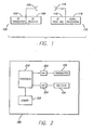
Fig. 1 is a conceptual block diagram of a RFID system including a base station and an RFID tag; -
Fig. 2 further illustrates the RFID base station depicted inFig. 1 ; -
Fig. 3 is a flow chart illustrating one embodiment of the present invention; and -
Fig. 4 is a flow chart illustrating another embodiment of the present invention. - The present invention provides a system and method for improving transmission rates in RFID base stations by implementing forced frequency "hops." In the detailed description that follows, like element numerals are used to describe like elements illustrated in one or more figures.
- An RFID system in accordance with the principles of the present invention is illustrated in the conceptual block diagram of
Fig. 1 . Abase station 100 includes (in part) anRF transmitter 102, anRF receiver 104, and anantenna 106 connected to thetransmitter 102 andreceiver 104. AnRFID tag 110 such as may be used in conjunction with thebase station 100 includes anRF front end 112, asignal processing section 116, and anantenna 114. TheRFID tag 110 may further include a memory (not shown) in which data may be stored, retrieved and/or written. - In reading the
RFID tag 110, thebase station 100 interrogates thetag 110 by generating an RF signal over a carrier frequency. The carrier frequency, and more particularly the amount of time spent transmitting over a particular carrier frequency, will be discussed in more detail below. The RF signal is coupled to theantenna 106 and transmitted to thetag 110. The RF signal emitted by theantenna 106 will, ostensibly, be received by thetag antenna 114 if thetag 110 is within the transmitting range of thebase station 100. If the field strength of the RF signal satisfies a predetermined read threshold requirement, theRFID tag 110 will respond to the reception of the signal by modulating the RF carrier to impart information about the tag onto the back-scattered RF field. The RF field is then propagated to thebase station 100, where the imparted information can be extracted. - A more detailed diagram of the
RFID base station 100 is shown inFig. 2 . Specifically, in a preferred embodiment, thebase station 100 includes amemory device 220 and aprocessor 210 connected to anRF transmitter 102 and anRF receiver 104 via a digital-to-analog (D/A)converter 202 and an analog-to-digital (A/D)converter 204, respectively. When interrogating the RFID tag, digital signal data (in accordance with information stored in thememory device 220 and information provided by a host application (not shown)) is provided by theprocessor 210, converted into analog signal data by the D/A converter 202, and transmitted to the RFID tag via the transmitter 102 (or more particularly via the antenna connected to the transmitter (seeFig. 1 )). Back-scattered data is then received by the receiver 104 (or more particularly the antenna connected to the receiver (seeFig. 1 )), converted into digital data by the A/D converter 204, and provided to the processor 210 (e.g., to be further processed, stored inmemory 220, provided to the host application (not shown), etc.). - It should be appreciated that the
memory device 220 depicted inFig. 2 includes, but is not limited to, RAM, cache memory, flash memory, EPROMs, EEPROMs, hard drives, removable drives and all other types of data storage devices generally known to those skilled in the art. It should further be appreciated that theprocessor 210 depicted inFig. 2 includes, but is not limited to, application specific integrated circuits (ASICs), processors, microprocessors, programmable devices and all other computing devices generally known to those skilled in the art. It should also be appreciated that the location, type, and/or number of components illustrated inFig. 2 are merely to exemplify the environment in which the present invention operates, and should not be considered limitations of the present invention. For example, a RFID base station including more than one memory device, having components in different locations (e.g., a D/A converter within the transmitter, a memory device external to the base station, etc.), or having additional (or fewer) components is within the scope of the present invention. - According to the present invention, the RFID base station is adapted to calculate whether enough time is available to perform the next transaction over the current carrier frequency or whether the base station should "hop" to a new carrier frequency before performing the transaction. This is because the Federal Communications Commission (FCC), for example, regulates the amount of time that can be spent on certain carrier frequencies. As described above, in Frequency Hopping Spread Spectrum (FHSS) devices, the FCC limits the time that can be spent (continuously) on a particular carrier frequency to four hundred milliseconds.
- Referring again to
Fig. 2 , the processor 210 (in conjunction with information stored inmemory 220 and/or information provided by the host application (not shown)) is adapted to determine whether enough time is available to perform the next transaction over the current carrier frequency or whether the base station should "hop" to a new carrier frequency before commencing the transaction. More particularly, in one embodiment of the present invention, the processor 210 (in conjunction with the stored and/or provided information) is adapted to (i) determine the amount of time available on a particular carrier frequency (e.g., pursuant to FCC regulations, ETSI regulations, etc.), (ii) determine the amount of time it would take to perform a particular transaction (e.g., transmit the next item of data, transmit the largest item of data (i.e., worst-case scenario), etc.), and (iii) force a "hop" to another carrier frequency if the transaction time is longer than the available time. - One method of increasing the transmission rate of an RFID base station is illustrated in
Fig. 3 . Specifically, starting atstep 300, the amount of time available on a particular carrier frequency is calculated atstep 310. In traditional RFID systems, this amount of time coincides with the next "hop" (i.e., "hop" after the allotted time expires). Atstep 320, the amount of time it would take to perform the longest possible transaction (i.e., the "worst-case" transaction) is determined. For example, if two possible transactions existed (i.e., data read and data write), a data read transaction takes fifty milliseconds, and a data write transaction takes one hundred milliseconds, the longer of the two transactions (i.e., data write) would be used. The information collected duringsteps step 350, ending the process atstep 360. Alternatively, if the answer is "No," then a "hop" is forced at step 340 (i.e., the base station "hops" to a new carrier frequency) and the next transaction is performed over the new carrier frequency atstep 350, ending the process atstep 360. - Another method of increasing the transmission rate of an RFID base station is illustrated in
Fig. 4 . Specifically, starting atstep 400, the amount of time available on a particular carrier frequency is calculated atstep 410. Atstep 420, the amount of time it would take to perform the next transaction (e.g., transmit the next item of information, etc.) is calculated. This information is then used atstep 430 to calculate whether the next transaction can be performed over the current carrier frequency (i.e., whether the transaction time is less than the available time). If the answer is "Yes," then the next transaction is performed atstep 450, ending the process atstep 460. Alternatively, if the answer is "No," then a "hop" is forced at step 440 (i.e., the base station "hops" to a new carrier frequency) and the next transaction is performed over the new frequency atstep 450, ending the process atstep 460. - Having thus described embodiments of a system and method for improving transmission rates in RFID base stations, it should be apparent to those skilled in the art that certain advantages of the system have been achieved. It should also be appreciated that various modifications, adaptations, and alternative embodiments thereof may be made within the scope of the present invention. The invention is defined by the following claims.
Claims (20)
- An RFID system, comprising:an RFID base station (100) adapted to communicate with at least one RFID transponder (110); said RFID base station (100) comprising:characterized in thata transmitter (102) adapted to transmit RF signals to said at least one RFID transponder (110);a receiver (104) adapted to receive RF signals backscattered from said at least one RFID transponder (110); anda processor (210) electrically connected to said transmitter (102) and said receiver (104),
the processor (210) is adapted to perform the following functions prior to starting a particular transaction:determine the amount of time available on a first carrier frequency;determine the amount of time it would take to perform the particular transaction; andchange to a second carrier frequency before said amount of time available on said first carrier frequency expires if said amount of time on said first carrier frequency is less than said amount of time it would take to perform said particular transaction,said processor (210) is further adapted to perform said particular transaction on said second carrier frequency. - The RFID system of Claim 1, wherein said particular transaction further comprises a next transaction, such that said processor (210) is adapted to determine the amount of time it would take to perform said next transaction.
- The RFID system of Claim 1, wherein said particular transaction further comprises a worst-case transaction, such that said processor (210) is adapted to determine the amount of time it would take to perform the longest possible transaction.
- The RFID system of Claim 1, wherein said particular transaction further comprises a worst-case transaction, such that said processor (210) is adapted to determine the amount of time it would take to perform the longest possible transaction with said at least one RFID transponder (110).
- The RFID system of Claim 1, wherein said particular transaction is a transmission of a particular RF signal, such that said processor (210) is adapted to determine the amount of time it would take to transmit said particular RF signal.
- The RFID system of Claim 1, wherein said particular transaction is both a transmission of a particular RF signal and an expected reception of a particular RF signal in response thereto, such that said processor (210) is adapted to determine the amount of time it would take to transmit said particular RF signal and the expected amount of time it would take to receive said particular RF signal in response thereto.
- The RFID system of Claim 1, further comprising said at least one RFID transponder (110).
- The RFID system of Claim 1, wherein said RFID base station (100) further comprises a memory device electrically connected to said processor (210), wherein said memory device is adapted to store at least partial program information as to when said processor (210) should hop to a different carrier frequency.
- The RFID system of Claim 1, further comprising a D/A converter (202), said D/A converter (202) electrically connecting said processor (210) to said transmitter (102).
- The RFID System of Claim 8, further comprising an A/D converter, said A/D converter electrically connecting said processor (210) to said receiver (104).
- The RFID system of Claim 1, further comprising a transceiver, said transceiver comprising said transmitter (102) and said receiver (104).
- A method for improving transmission rates in an RFID base station (100), comprising:performing a first transaction with at least one RFID transponder (110) over a first carrier frequency;characterized by
before starting another particular transaction,
determining the amount of time available on said first carrier frequency;
determining the amount of time it would take to perform said particular transaction; and
forcing said RFID base station (100) to hop to a second carrier frequency before said amount of time available on said first carrier frequency expires if said amount of time on said first carrier frequency is less than said amount of time it would take to perform said particular transaction, and
performing said particular transaction on said second carrier frequency. - The method of Claim 12, wherein said step of determining the amount of time it would take to perform said particular transaction further comprises determining the amount of time it would take to perform a second transaction.
- The method of Claim 12, wherein said step of determining the amount of time it would take to perform said particular transaction further comprises determining the amount of time it would take to perform a worst-case transaction, said worst-case transaction being the longest transaction that can be performed by said RFID base station (100).
- The method of Claim 12, wherein said step of determining the amount of time it would take to perform said particular transaction further comprises determining the amount of time it would take to perform a worst-case transaction, said worst-case transaction being the longest transaction that can be performed by said RFID base station (100) and with said at least one RFID transponder (110).
- The method of Claim 12, wherein said step of determining the amount of time it would take to perform said particular transaction further comprises determining the amount of time it would take to transmit a particular radio frequency (RF) signal.
- The method of Claim 12, wherein said step of determining the amount of time it would take to perform said particular transaction further comprises determining the amount of time it would take to transmit a particular radio frequency (RF) signal and an amount of time that it might take to receive a responsive RF signal from said at least one RFID transponder (110).
- The method of Claim 16, wherein said step of performing a first transaction with at least one RFID transponder (110) further comprises transmitting a first RF signal to said at least one RFID transponder (110), said first RF signal and said particular RF signal each comprising information selected from a list of information consisting of commands and data.
- The method of Claim 12, wherein said step of determining the amount of time available on said first carrier frequency further comprises comparing the amount of time that the RFID base station (100) has continuously been on said first carrier frequency to an amount of time permitted by the Federal Communications Commission.
- The method of Claim 12, wherein said step of determining the amount of time it would take to perform said particular transaction with said at least one RFID transponder (110) is performed prior to said step of determining the amount of time available on said first carrier frequency.
Applications Claiming Priority (3)
| Application Number | Priority Date | Filing Date | Title |
|---|---|---|---|
| US45941403P | 2003-03-31 | 2003-03-31 | |
| US10/814,411 US7103087B2 (en) | 2003-03-31 | 2004-03-30 | Frequency hopping spread spectrum scheme for RFID reader |
| PCT/US2004/010019 WO2004090783A2 (en) | 2003-03-31 | 2004-03-31 | Frequency hopping spread spectrum scheme for rfid reader |
Publications (3)
| Publication Number | Publication Date |
|---|---|
| EP1629412A2 EP1629412A2 (en) | 2006-03-01 |
| EP1629412A4 EP1629412A4 (en) | 2007-03-21 |
| EP1629412B1 true EP1629412B1 (en) | 2008-08-13 |
Family
ID=32995061
Family Applications (1)
| Application Number | Title | Priority Date | Filing Date |
|---|---|---|---|
| EP04758720A Expired - Lifetime EP1629412B1 (en) | 2003-03-31 | 2004-03-31 | Frequency hopping spread spectrum scheme for rfid reader |
Country Status (6)
| Country | Link |
|---|---|
| US (1) | US7103087B2 (en) |
| EP (1) | EP1629412B1 (en) |
| KR (1) | KR20060013496A (en) |
| AT (1) | ATE404935T1 (en) |
| DE (1) | DE602004015776D1 (en) |
| WO (1) | WO2004090783A2 (en) |
Families Citing this family (25)
| Publication number | Priority date | Publication date | Assignee | Title |
|---|---|---|---|---|
| US20050179521A1 (en) * | 2004-02-12 | 2005-08-18 | Intermec Ip Corp. | Frequency hopping method for RFID tag |
| JP4086833B2 (en) | 2004-10-27 | 2008-05-14 | 日本電波工業株式会社 | High frequency radio control method and high frequency radio system |
| US7551081B2 (en) | 2004-11-10 | 2009-06-23 | Rockwell Automation Technologies, Inc. | Systems and methods that integrate radio frequency identification (RFID) technology with agent-based control systems |
| US7339476B2 (en) | 2004-11-10 | 2008-03-04 | Rockwell Automation Technologies, Inc. | Systems and methods that integrate radio frequency identification (RFID) technology with industrial controllers |
| US7388491B2 (en) | 2005-07-20 | 2008-06-17 | Rockwell Automation Technologies, Inc. | Mobile RFID reader with integrated location awareness for material tracking and management |
| US7764191B2 (en) | 2005-07-26 | 2010-07-27 | Rockwell Automation Technologies, Inc. | RFID tag data affecting automation controller with internal database |
| US8260948B2 (en) | 2005-08-10 | 2012-09-04 | Rockwell Automation Technologies, Inc. | Enhanced controller utilizing RFID technology |
| US7510110B2 (en) | 2005-09-08 | 2009-03-31 | Rockwell Automation Technologies, Inc. | RFID architecture in an industrial controller environment |
| US7931197B2 (en) | 2005-09-20 | 2011-04-26 | Rockwell Automation Technologies, Inc. | RFID-based product manufacturing and lifecycle management |
| US7446662B1 (en) | 2005-09-26 | 2008-11-04 | Rockwell Automation Technologies, Inc. | Intelligent RFID tag for magnetic field mapping |
| US8025227B2 (en) * | 2005-09-30 | 2011-09-27 | Rockwell Automation Technologies, Inc. | Access to distributed databases via pointer stored in RFID tag |
| US7482926B2 (en) * | 2005-10-28 | 2009-01-27 | Intermec Ip Corp. | System and method of enhancing range in a radio frequency identification system |
| KR100791025B1 (en) | 2005-12-31 | 2008-01-03 | 주식회사 유컴테크놀러지 | Method for air-channel access in mobile rfid and method for partition into tag zones using the method thereof |
| US7592897B2 (en) | 2006-04-25 | 2009-09-22 | Impinj, Inc. | RFID readers system and methods for early hopping out of a frequency channel in the presence of RF interference |
| TWI431380B (en) * | 2006-05-12 | 2014-03-21 | Photon Dynamics Inc | Deposition repair apparatus and methods |
| US8098159B2 (en) * | 2006-06-09 | 2012-01-17 | Intelleflex Corporation | RF device comparing DAC output to incoming signal for selectively performing an action |
| US7920046B1 (en) * | 2006-07-21 | 2011-04-05 | Impinj, Inc. | RFID readers and systems initializing after antenna switch and methods |
| US8120494B1 (en) | 2006-07-21 | 2012-02-21 | Impinj, Inc. | RFID readers and systems with antenna switching upon detecting too few tags and methods |
| US7885763B2 (en) * | 2006-12-01 | 2011-02-08 | Hand Held Products, Inc. | Apparatus and methods for tracking movement of persons |
| US8728589B2 (en) * | 2007-09-14 | 2014-05-20 | Photon Dynamics, Inc. | Laser decal transfer of electronic materials |
| US20090257474A1 (en) * | 2008-04-15 | 2009-10-15 | Keystone Technology Solutions, Llc | Fast hop frequency hopping protocol |
| US20100188251A1 (en) * | 2009-01-23 | 2010-07-29 | Panuce Donald G | Apparatus and method for an ac wireless switch |
| US20100246399A1 (en) * | 2009-03-24 | 2010-09-30 | Qualcomm Incorporated | Multi-channel management and load balancing |
| US8977282B2 (en) * | 2009-03-24 | 2015-03-10 | Qualcomm Incorporated | Multi-channel management and load balancing |
| US10819422B2 (en) | 2018-12-30 | 2020-10-27 | Garman Engineering, LLC | Low power radio modem |
Family Cites Families (11)
| Publication number | Priority date | Publication date | Assignee | Title |
|---|---|---|---|---|
| US5471469A (en) * | 1994-02-08 | 1995-11-28 | Metricon, Inc. | Method of resolving media contention in radio communication links |
| US5533025A (en) * | 1994-09-26 | 1996-07-02 | International Business Machines Corporation | Robust frequency management and acquisition in a wireless local area network that uses frequency-hopping radios |
| WO1998059436A1 (en) * | 1997-06-24 | 1998-12-30 | Siemens Aktiengesellschaft | Method and device for radiotransmission |
| US6434183B1 (en) * | 1997-08-14 | 2002-08-13 | Siemens Aktiengesellschaft | Method and device for radio transmission of data by means of frequency hops |
| US6486769B1 (en) * | 1999-12-22 | 2002-11-26 | Intermec Ip Corp. | Method and system for automatic adjustment and diagnosis of radio frequency identification systems using programmable checktags |
| GB0100093D0 (en) * | 2001-01-03 | 2001-02-14 | Vtech Communications Ltd | Adaptive frequency hopping strategy |
| US7035275B2 (en) * | 2001-01-16 | 2006-04-25 | Texas Instruments Incorporated | Non-collaborative mechanisms for enhanced coexistence of wireless networks |
| US7009515B2 (en) * | 2001-04-11 | 2006-03-07 | Battelle Memorial Institute K1-53 | Frequency-hopping RFID system |
| US6862438B2 (en) * | 2002-03-25 | 2005-03-01 | Broadcom Corporation | Programmable gain amplifier (PGA) with AGC in receiver section |
| US7035313B2 (en) * | 2002-04-09 | 2006-04-25 | Fry Terry L | Narrow bandwidth, high resolution video surveillance system and frequency hopped, spread spectrum transmission method |
| US20050141562A1 (en) * | 2003-12-30 | 2005-06-30 | Nokia Corporation | Method for reducing radio interference in a frequency-hopping radio network |
-
2004
- 2004-03-30 US US10/814,411 patent/US7103087B2/en not_active Expired - Lifetime
- 2004-03-31 KR KR1020057018724A patent/KR20060013496A/en not_active Application Discontinuation
- 2004-03-31 WO PCT/US2004/010019 patent/WO2004090783A2/en active Application Filing
- 2004-03-31 EP EP04758720A patent/EP1629412B1/en not_active Expired - Lifetime
- 2004-03-31 AT AT04758720T patent/ATE404935T1/en not_active IP Right Cessation
- 2004-03-31 DE DE602004015776T patent/DE602004015776D1/en not_active Expired - Fee Related
Also Published As
| Publication number | Publication date |
|---|---|
| US20040189443A1 (en) | 2004-09-30 |
| KR20060013496A (en) | 2006-02-10 |
| US7103087B2 (en) | 2006-09-05 |
| DE602004015776D1 (en) | 2008-09-25 |
| WO2004090783A2 (en) | 2004-10-21 |
| WO2004090783A3 (en) | 2005-09-22 |
| EP1629412A4 (en) | 2007-03-21 |
| ATE404935T1 (en) | 2008-08-15 |
| EP1629412A2 (en) | 2006-03-01 |
Similar Documents
| Publication | Publication Date | Title |
|---|---|---|
| EP1629412B1 (en) | Frequency hopping spread spectrum scheme for rfid reader | |
| EP1832004B1 (en) | Ultra wideband radio frequency identification techniques | |
| EP2248066B1 (en) | Interrogation of rfid communication units | |
| US7026935B2 (en) | Method and apparatus to configure an RFID system to be adaptable to a plurality of environmental conditions | |
| KR100641380B1 (en) | Anti-collision method between readers of rfid system | |
| US7479874B2 (en) | Verification of singulated RFID tags by RFID readers | |
| US20070075838A1 (en) | Method and apparatus for avoiding radio frequency identification (RFID) tag response collisions | |
| US11874365B2 (en) | Passive radio frequency identification ranging | |
| EP2124167A1 (en) | Interrogating Device, RFID interrogator, and RFID interrogating method | |
| CN101517599A (en) | Apparatus and method for integrated reader and tag | |
| EP2267634A1 (en) | Method and apparatus for providing energy to passive tags in a radio-frequency identification system | |
| EP2701314B1 (en) | Detection of load-modulated NFC signals | |
| Yu et al. | Reducing reader collision for mobile RFID | |
| KR100722168B1 (en) | Rfid system for communicating readers among tags | |
| EP1832999A1 (en) | Tag communication device and tag communicating method | |
| EP2070002B1 (en) | Programmable chip design for radio frequency signal generation and method therefor | |
| EP2987113B1 (en) | Defining a radio frequency identification read area | |
| US20090257473A1 (en) | RFID Fast Hop Frequency Hopping | |
| US20090257474A1 (en) | Fast hop frequency hopping protocol | |
| KR20070036624A (en) | Appratus and method for receiving tag signal in mobile rfid reader | |
| US7447251B2 (en) | Frequency hopping spread spectrum scheme for RFID reader | |
| KR100858053B1 (en) | A Passive RFID Reader and Operation Control Method | |
| KR100842342B1 (en) | Method for avoiding collision using by synchronization between rfid readers at congested environment | |
| KR100863186B1 (en) | Method for slotted random anti-collision for rfid and rfid tag for this method | |
| WO2008059196A1 (en) | A method of controlling transmission time for an active radio frequency identification tag transponder transmission device in active radio frequency identification apparatus |
Legal Events
| Date | Code | Title | Description |
|---|---|---|---|
| PUAI | Public reference made under article 153(3) epc to a published international application that has entered the european phase |
Free format text: ORIGINAL CODE: 0009012 |
|
| 17P | Request for examination filed |
Effective date: 20051011 |
|
| AK | Designated contracting states |
Kind code of ref document: A2 Designated state(s): AT BE BG CH CY CZ DE DK EE ES FI FR GB GR HU IE IT LI LU MC NL PL PT RO SE SI SK TR |
|
| AX | Request for extension of the european patent |
Extension state: AL LT LV MK |
|
| DAX | Request for extension of the european patent (deleted) | ||
| RIC1 | Information provided on ipc code assigned before grant |
Ipc: H04B 1/713 20060101AFI20061016BHEP |
|
| A4 | Supplementary search report drawn up and despatched |
Effective date: 20070221 |
|
| RIC1 | Information provided on ipc code assigned before grant |
Ipc: H04B 1/713 20060101ALI20070215BHEP Ipc: G06K 7/00 20060101AFI20070215BHEP |
|
| 17Q | First examination report despatched |
Effective date: 20070514 |
|
| GRAP | Despatch of communication of intention to grant a patent |
Free format text: ORIGINAL CODE: EPIDOSNIGR1 |
|
| GRAS | Grant fee paid |
Free format text: ORIGINAL CODE: EPIDOSNIGR3 |
|
| GRAA | (expected) grant |
Free format text: ORIGINAL CODE: 0009210 |
|
| AK | Designated contracting states |
Kind code of ref document: B1 Designated state(s): AT BE BG CH CY CZ DE DK EE ES FI FR GB GR HU IE IT LI LU MC NL PL PT RO SE SI SK TR |
|
| REG | Reference to a national code |
Ref country code: GB Ref legal event code: FG4D |
|
| REG | Reference to a national code |
Ref country code: CH Ref legal event code: EP |
|
| REG | Reference to a national code |
Ref country code: IE Ref legal event code: FG4D |
|
| REF | Corresponds to: |
Ref document number: 602004015776 Country of ref document: DE Date of ref document: 20080925 Kind code of ref document: P |
|
| PG25 | Lapsed in a contracting state [announced via postgrant information from national office to epo] |
Ref country code: ES Free format text: LAPSE BECAUSE OF FAILURE TO SUBMIT A TRANSLATION OF THE DESCRIPTION OR TO PAY THE FEE WITHIN THE PRESCRIBED TIME-LIMIT Effective date: 20081124 Ref country code: NL Free format text: LAPSE BECAUSE OF FAILURE TO SUBMIT A TRANSLATION OF THE DESCRIPTION OR TO PAY THE FEE WITHIN THE PRESCRIBED TIME-LIMIT Effective date: 20080813 |
|
| PG25 | Lapsed in a contracting state [announced via postgrant information from national office to epo] |
Ref country code: FI Free format text: LAPSE BECAUSE OF FAILURE TO SUBMIT A TRANSLATION OF THE DESCRIPTION OR TO PAY THE FEE WITHIN THE PRESCRIBED TIME-LIMIT Effective date: 20080813 Ref country code: SI Free format text: LAPSE BECAUSE OF FAILURE TO SUBMIT A TRANSLATION OF THE DESCRIPTION OR TO PAY THE FEE WITHIN THE PRESCRIBED TIME-LIMIT Effective date: 20080813 Ref country code: AT Free format text: LAPSE BECAUSE OF FAILURE TO SUBMIT A TRANSLATION OF THE DESCRIPTION OR TO PAY THE FEE WITHIN THE PRESCRIBED TIME-LIMIT Effective date: 20080813 |
|
| PG25 | Lapsed in a contracting state [announced via postgrant information from national office to epo] |
Ref country code: BE Free format text: LAPSE BECAUSE OF FAILURE TO SUBMIT A TRANSLATION OF THE DESCRIPTION OR TO PAY THE FEE WITHIN THE PRESCRIBED TIME-LIMIT Effective date: 20080813 |
|
| PG25 | Lapsed in a contracting state [announced via postgrant information from national office to epo] |
Ref country code: BG Free format text: LAPSE BECAUSE OF FAILURE TO SUBMIT A TRANSLATION OF THE DESCRIPTION OR TO PAY THE FEE WITHIN THE PRESCRIBED TIME-LIMIT Effective date: 20081113 Ref country code: DK Free format text: LAPSE BECAUSE OF FAILURE TO SUBMIT A TRANSLATION OF THE DESCRIPTION OR TO PAY THE FEE WITHIN THE PRESCRIBED TIME-LIMIT Effective date: 20080813 |
|
| PG25 | Lapsed in a contracting state [announced via postgrant information from national office to epo] |
Ref country code: PT Free format text: LAPSE BECAUSE OF FAILURE TO SUBMIT A TRANSLATION OF THE DESCRIPTION OR TO PAY THE FEE WITHIN THE PRESCRIBED TIME-LIMIT Effective date: 20090113 Ref country code: CZ Free format text: LAPSE BECAUSE OF FAILURE TO SUBMIT A TRANSLATION OF THE DESCRIPTION OR TO PAY THE FEE WITHIN THE PRESCRIBED TIME-LIMIT Effective date: 20080813 Ref country code: SK Free format text: LAPSE BECAUSE OF FAILURE TO SUBMIT A TRANSLATION OF THE DESCRIPTION OR TO PAY THE FEE WITHIN THE PRESCRIBED TIME-LIMIT Effective date: 20080813 Ref country code: RO Free format text: LAPSE BECAUSE OF FAILURE TO SUBMIT A TRANSLATION OF THE DESCRIPTION OR TO PAY THE FEE WITHIN THE PRESCRIBED TIME-LIMIT Effective date: 20080813 |
|
| PLBE | No opposition filed within time limit |
Free format text: ORIGINAL CODE: 0009261 |
|
| STAA | Information on the status of an ep patent application or granted ep patent |
Free format text: STATUS: NO OPPOSITION FILED WITHIN TIME LIMIT |
|
| 26N | No opposition filed |
Effective date: 20090514 |
|
| PG25 | Lapsed in a contracting state [announced via postgrant information from national office to epo] |
Ref country code: EE Free format text: LAPSE BECAUSE OF FAILURE TO SUBMIT A TRANSLATION OF THE DESCRIPTION OR TO PAY THE FEE WITHIN THE PRESCRIBED TIME-LIMIT Effective date: 20080813 |
|
| PG25 | Lapsed in a contracting state [announced via postgrant information from national office to epo] |
Ref country code: IT Free format text: LAPSE BECAUSE OF FAILURE TO SUBMIT A TRANSLATION OF THE DESCRIPTION OR TO PAY THE FEE WITHIN THE PRESCRIBED TIME-LIMIT Effective date: 20080813 |
|
| PG25 | Lapsed in a contracting state [announced via postgrant information from national office to epo] |
Ref country code: MC Free format text: LAPSE BECAUSE OF NON-PAYMENT OF DUE FEES Effective date: 20090331 |
|
| REG | Reference to a national code |
Ref country code: CH Ref legal event code: PL |
|
| GBPC | Gb: european patent ceased through non-payment of renewal fee |
Effective date: 20090331 |
|
| REG | Reference to a national code |
Ref country code: FR Ref legal event code: ST Effective date: 20091130 |
|
| REG | Reference to a national code |
Ref country code: IE Ref legal event code: MM4A |
|
| PG25 | Lapsed in a contracting state [announced via postgrant information from national office to epo] |
Ref country code: LI Free format text: LAPSE BECAUSE OF NON-PAYMENT OF DUE FEES Effective date: 20090331 Ref country code: CH Free format text: LAPSE BECAUSE OF NON-PAYMENT OF DUE FEES Effective date: 20090331 Ref country code: DE Free format text: LAPSE BECAUSE OF NON-PAYMENT OF DUE FEES Effective date: 20091001 Ref country code: IE Free format text: LAPSE BECAUSE OF NON-PAYMENT OF DUE FEES Effective date: 20090331 Ref country code: SE Free format text: LAPSE BECAUSE OF FAILURE TO SUBMIT A TRANSLATION OF THE DESCRIPTION OR TO PAY THE FEE WITHIN THE PRESCRIBED TIME-LIMIT Effective date: 20081113 |
|
| PG25 | Lapsed in a contracting state [announced via postgrant information from national office to epo] |
Ref country code: FR Free format text: LAPSE BECAUSE OF NON-PAYMENT OF DUE FEES Effective date: 20091123 Ref country code: GB Free format text: LAPSE BECAUSE OF NON-PAYMENT OF DUE FEES Effective date: 20090331 |
|
| PG25 | Lapsed in a contracting state [announced via postgrant information from national office to epo] |
Ref country code: PL Free format text: LAPSE BECAUSE OF FAILURE TO SUBMIT A TRANSLATION OF THE DESCRIPTION OR TO PAY THE FEE WITHIN THE PRESCRIBED TIME-LIMIT Effective date: 20080813 |
|
| PG25 | Lapsed in a contracting state [announced via postgrant information from national office to epo] |
Ref country code: GR Free format text: LAPSE BECAUSE OF FAILURE TO SUBMIT A TRANSLATION OF THE DESCRIPTION OR TO PAY THE FEE WITHIN THE PRESCRIBED TIME-LIMIT Effective date: 20081114 |
|
| PG25 | Lapsed in a contracting state [announced via postgrant information from national office to epo] |
Ref country code: LU Free format text: LAPSE BECAUSE OF NON-PAYMENT OF DUE FEES Effective date: 20090331 |
|
| PG25 | Lapsed in a contracting state [announced via postgrant information from national office to epo] |
Ref country code: HU Free format text: LAPSE BECAUSE OF FAILURE TO SUBMIT A TRANSLATION OF THE DESCRIPTION OR TO PAY THE FEE WITHIN THE PRESCRIBED TIME-LIMIT Effective date: 20090214 |
|
| PG25 | Lapsed in a contracting state [announced via postgrant information from national office to epo] |
Ref country code: TR Free format text: LAPSE BECAUSE OF FAILURE TO SUBMIT A TRANSLATION OF THE DESCRIPTION OR TO PAY THE FEE WITHIN THE PRESCRIBED TIME-LIMIT Effective date: 20080813 |
|
| PG25 | Lapsed in a contracting state [announced via postgrant information from national office to epo] |
Ref country code: CY Free format text: LAPSE BECAUSE OF FAILURE TO SUBMIT A TRANSLATION OF THE DESCRIPTION OR TO PAY THE FEE WITHIN THE PRESCRIBED TIME-LIMIT Effective date: 20080813 |