EP1647708A1 - Pitch drive system for a wind turbine - Google Patents
Pitch drive system for a wind turbine Download PDFInfo
- Publication number
- EP1647708A1 EP1647708A1 EP04024520A EP04024520A EP1647708A1 EP 1647708 A1 EP1647708 A1 EP 1647708A1 EP 04024520 A EP04024520 A EP 04024520A EP 04024520 A EP04024520 A EP 04024520A EP 1647708 A1 EP1647708 A1 EP 1647708A1
- Authority
- EP
- European Patent Office
- Prior art keywords
- drive
- emergency
- regulation
- pitch
- wind turbine
- Prior art date
- Legal status (The legal status is an assumption and is not a legal conclusion. Google has not performed a legal analysis and makes no representation as to the accuracy of the status listed.)
- Withdrawn
Links
- 230000033228 biological regulation Effects 0.000 claims abstract description 51
- 230000001105 regulatory effect Effects 0.000 claims abstract description 3
- 238000003860 storage Methods 0.000 claims description 7
- 238000004146 energy storage Methods 0.000 claims description 5
- 210000003746 feather Anatomy 0.000 description 4
- 238000012986 modification Methods 0.000 description 2
- 230000004048 modification Effects 0.000 description 2
- 238000000926 separation method Methods 0.000 description 2
- 230000000712 assembly Effects 0.000 description 1
- 238000000429 assembly Methods 0.000 description 1
- 230000001276 controlling effect Effects 0.000 description 1
- 230000001419 dependent effect Effects 0.000 description 1
- 230000000694 effects Effects 0.000 description 1
- 238000012423 maintenance Methods 0.000 description 1
- 230000014759 maintenance of location Effects 0.000 description 1
- 238000004519 manufacturing process Methods 0.000 description 1
- 238000010248 power generation Methods 0.000 description 1
Images


Classifications
-
- F—MECHANICAL ENGINEERING; LIGHTING; HEATING; WEAPONS; BLASTING
- F03—MACHINES OR ENGINES FOR LIQUIDS; WIND, SPRING, OR WEIGHT MOTORS; PRODUCING MECHANICAL POWER OR A REACTIVE PROPULSIVE THRUST, NOT OTHERWISE PROVIDED FOR
- F03D—WIND MOTORS
- F03D7/00—Controlling wind motors
- F03D7/02—Controlling wind motors the wind motors having rotation axis substantially parallel to the air flow entering the rotor
- F03D7/022—Adjusting aerodynamic properties of the blades
- F03D7/0224—Adjusting blade pitch
-
- F—MECHANICAL ENGINEERING; LIGHTING; HEATING; WEAPONS; BLASTING
- F05—INDEXING SCHEMES RELATING TO ENGINES OR PUMPS IN VARIOUS SUBCLASSES OF CLASSES F01-F04
- F05B—INDEXING SCHEME RELATING TO WIND, SPRING, WEIGHT, INERTIA OR LIKE MOTORS, TO MACHINES OR ENGINES FOR LIQUIDS COVERED BY SUBCLASSES F03B, F03D AND F03G
- F05B2270/00—Control
- F05B2270/10—Purpose of the control system
- F05B2270/107—Purpose of the control system to cope with emergencies
-
- F—MECHANICAL ENGINEERING; LIGHTING; HEATING; WEAPONS; BLASTING
- F05—INDEXING SCHEMES RELATING TO ENGINES OR PUMPS IN VARIOUS SUBCLASSES OF CLASSES F01-F04
- F05B—INDEXING SCHEME RELATING TO WIND, SPRING, WEIGHT, INERTIA OR LIKE MOTORS, TO MACHINES OR ENGINES FOR LIQUIDS COVERED BY SUBCLASSES F03B, F03D AND F03G
- F05B2270/00—Control
- F05B2270/60—Control system actuates through
- F05B2270/602—Control system actuates through electrical actuators
-
- F—MECHANICAL ENGINEERING; LIGHTING; HEATING; WEAPONS; BLASTING
- F05—INDEXING SCHEMES RELATING TO ENGINES OR PUMPS IN VARIOUS SUBCLASSES OF CLASSES F01-F04
- F05B—INDEXING SCHEME RELATING TO WIND, SPRING, WEIGHT, INERTIA OR LIKE MOTORS, TO MACHINES OR ENGINES FOR LIQUIDS COVERED BY SUBCLASSES F03B, F03D AND F03G
- F05B2270/00—Control
- F05B2270/60—Control system actuates through
- F05B2270/604—Control system actuates through hydraulic actuators
-
- F—MECHANICAL ENGINEERING; LIGHTING; HEATING; WEAPONS; BLASTING
- F05—INDEXING SCHEMES RELATING TO ENGINES OR PUMPS IN VARIOUS SUBCLASSES OF CLASSES F01-F04
- F05B—INDEXING SCHEME RELATING TO WIND, SPRING, WEIGHT, INERTIA OR LIKE MOTORS, TO MACHINES OR ENGINES FOR LIQUIDS COVERED BY SUBCLASSES F03B, F03D AND F03G
- F05B2270/00—Control
- F05B2270/60—Control system actuates through
- F05B2270/606—Control system actuates through mechanical actuators
-
- Y—GENERAL TAGGING OF NEW TECHNOLOGICAL DEVELOPMENTS; GENERAL TAGGING OF CROSS-SECTIONAL TECHNOLOGIES SPANNING OVER SEVERAL SECTIONS OF THE IPC; TECHNICAL SUBJECTS COVERED BY FORMER USPC CROSS-REFERENCE ART COLLECTIONS [XRACs] AND DIGESTS
- Y02—TECHNOLOGIES OR APPLICATIONS FOR MITIGATION OR ADAPTATION AGAINST CLIMATE CHANGE
- Y02E—REDUCTION OF GREENHOUSE GAS [GHG] EMISSIONS, RELATED TO ENERGY GENERATION, TRANSMISSION OR DISTRIBUTION
- Y02E10/00—Energy generation through renewable energy sources
- Y02E10/70—Wind energy
- Y02E10/72—Wind turbines with rotation axis in wind direction
Definitions
- the present invention relates to a pitch drive system for a wind turbine, particularly to a pitch drive system which comprises a regulation drive for regulating the pitch of a rotor blade of said wind turbine during normal operation, and an emergency drive for pitching the rotor blade in case of emergency.
- the present invention further relates to wind turbines with pitch drive systems comprising both a regulation drive and an emergency drive.
- modem wind turbines have rotor blades with adjustable pitch angle.
- the rotor blades can be rotated about their longitudinal axis by means of a pitch drive disposed in the rotor hub.
- the pitch drive is actuated electrically or hydraulically.
- the power generation of the wind turbine can be controlled as well as an aerodynamical braking of the rotor can be accomplished.
- the rotor blades generate a braking torque when moved into feather position. Thereby, the rotor blades ensure that the rotor is not further accelerated and, thus, the rotor blades form an aerodynamical brake for the wind turbine.
- the aerodynamical brake effect of the rotor blades is also used for braking the rotor in case of emergency, e.g. when a failure of the drive system occurs or when the wind turbine is in an uncontrolled condition. Accordingly, it is very important that the emergency system works absolutely reliable even when the wind turbine is damaged or in an uncontrolled state, e.g. due to lightning. Especially, the pitch drive is required to function even in a power outage condition.
- a further problem associated with the above prior art pitch drive systems is that failure in the electrical drive system leads to a shutdown of the wind turbine so that a yield loss occurs.
- a pitch drive system which comprises more than one drive train for each rotor blade.
- each of the drive trains comprises an electric motor with battery backup for emergency. Accordingly, the pitch drive system of DE 101 16 011 is still fault-prone in cases where the electronics of the wind turbine is damaged, e.g., by lightning.
- control drive and regulation drive are used interchangeably.
- emergency drive and auxiliary drive are used interchangeably.
- a pitch drive system for a wind turbine which has a control drive for controlling the pitch of a rotor blade of said wind turbine during normal operating conditions and an auxiliary drive for pitching the rotor blade to accomplish an emergency shutdown.
- the control drive as well as the auxiliary drive each comprise a drive section which are disjoint from each other.
- the pitch drive system can be designed in a modular manner which does not only facilitate the assembly of the system but does also increase the operational safety and reliability. Particularly, the risk that the emergency drive cannot operate due to a gear box failure of the regulation drive is eliminated. This reliability aspect is especially important for off-shore applications where maintenance is costly, complicated and scheduled at large intervals.
- the emergency drive comprises at least one further drive train.
- a further redundancy of the emergency drive provided so that the operational safety and reliability of the pitch drive system are further improved.
- the separation of the emergency drive into two or more separate drive trains reduces the risk of a failure of the emergency drive because of enhanced redundancy.
- a further advantage of this embodiment is that a modular structure of the emergency drive can be established.
- emergency drive modules providing a predetermined torque can be manufactured independently from the design of the wind turbine pitch drive. When dimensioning the emergency drive, a sufficient number of these modules is assembled to provide the required total torque to feather the rotor blade.
- more emergency drive modules than necessary can be assembled to provide redundancy so that sufficient torque is applied even in a case where one or more emergency drive modules fail.
- a control drive for a pitch drive system which comprises a pinion wheel for meshing with a toothed wheel, a gear box coupled to the pinion wheel, and at least two motors coupled to said gear box.
- the regulation drive according to this aspect prevents a system shutdown when one of the motors fails since the other motor can still operate the regulation drive.
- the wind turbine can stay in operation and the yield is not reduced.
- the redundancy requirements for the regulation drive are not as high as for the emergency drive. Therefore, the small risk that a gear box failure occurs is acceptable for the regulation drive.
- the more important aspect with respect to the regulation drive is that the motors are coupled to the same gear box so that space is saved.
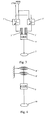
- Fig. 1 shows an embodiment of the present invention according to a first aspect of the present invention.
- the pitch drive system comprises a regulation drive 1 and an emergency drive 2.
- the regulation drive 1 and the emergency drive 2 comprise separate drive trains.
- the complexity of the individual drive train assemblies 1, 2 is lowered compared to drive trains where regulation drive and emergency drive share a drive train.
- the regulation drive 1 comprises an actuator 3, a gearbox 4 and a pinion wheel 5.
- Actuator 3 is coupled to gear box 4 and pinion wheel 5 engages with an internal toothing of internal gear 6.
- the actuator 3 is coupled to a power supply and a control unit (not shown) via servo amplifier 7.
- actuator 3 is an electric motor, e.g., an DC motor or a three-phase asynchronous motor.
- the actuator 3 may comprise a hydraulic element.
- the emergency drive 2 comprises an actuator 8, a gear box 9 and a pinion wheel 10.
- Actuator 8 is coupled to gear box 9 and pinion wheel 10 engages with the internal toothing of internal gear 6.
- actuator 8 is a mechanical energy storage, e.g. a spring storage.
- actuator 8 may comprise a hydraulic pressure storage.
- the pitch of a rotor blade coupled to gear 6 is controlled via regulation drive 1.
- a control signal is applied to servo amplifier 7 and motor 3 is supplied with power.
- the motor torque of motor 3 is applied to gear 6 via gear box 4 and pinion wheel 5.
- the rotor blade is rotated around its longitudinal axis.
- the mechanical energy stored in actuator 8 is released and torque is applied to gear 6 via gear box 9 and pinion wheel 10.
- the rotor blade is rotated around its longitudinal axis into feather position and the wind turbine is braked.
- the mechanical energy is stored in spring storages as they are described, e.g., in international patent application PCT/EP2004/008444 which is hereby incorporated by reference.
- a hydraulic element may be used to store mechanical energy in form of hydraulic pressure.
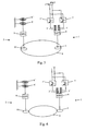
- the pitch drive system comprises a regulation drive 1 and an emergency drive 2 which are identical to those shown in Fig. 1.
- the pinion wheels 5 and 10 of regulation drive 1 and emergency drive 2 engage with an external toothing of gear 6.
- the regulation drive of the present embodiment comprises first and second actuators 3', 3" which are coupled to the same gear box 4.
- the regulation drive according to this embodiment prevents a system shutdown when only one of the actuators fails since the other actuator can still operate the regulation drive.
- the wind turbine can stay in operation and the yield is not reduced even though the pitch velocity may be derated.
- actuators 3', 3" are electric motors, e.g., DC motors or three-phase asynchronous motors.
- actuators 3', 3" may each comprise a hydraulic element.
- Each of the motors 3', 3" is coupled to a power supply and a control unit via a respective servo amplifier 7', 7".
- Fig. 4 shows an emergency drive according to another embodiment of the present invention.
- a first actuator 8' and a second actuator 8" are coupled to the same gear box 9.
- twice of the torque is provided in case of emergency.
- the redundancy of the emergency drive is increased so that a failure of the emergency drive becomes more unlikely.
- Fig. 5 shows a further embodiment of the present invention which has a similar structure than the embodiment shown in Fig. 1.
- the regulation drive 1 is formed according to the embodiment shown in Fig. 3, i.e. it comprises two motors 3', 3" coupled to the same gear box 4.
- the emergency drive 2 is formed according to the embodiment shown in Fig. 4, i.e. it comprises two mechanical energy storages 8', 8" coupled to the same gear box 9.
- the pinion wheels 5, 10 of regulation drive 1 and emergency drive 2 mesh with the internal toothing of internal gear 6.
- FIG. 6 An alternative embodiment similar to the one of Fig. 5 is shown in Fig. 6.
- the principal design of the regulation drive 1 and the emergency drive 2 is identical to the embodiment shown in Fig. 5.
- the pinion wheels 5, 10 mesh with an external toothing of gear 6.
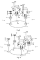
- Fig. 7 shows a further embodiment of the present invention.
- the regulation drive 1 is formed according to the embodiment shown in Fig. 3, i.e. it comprises two motors 3', 3" coupled to the same gear box 4.
- the emergency drive 2 comprises two separate drive trains, each of them having a mechanical energy storage 8, 108, a gear box 9, 109, and a pinion wheel 10, 110.
- the pinion wheels 5, 10, 110 of regulation drive 1 and emergency drive 2 mesh with the internal toothing of internal gear 6.
- FIG. 8 An alternative embodiment similar to the one of Fig. 7 is shown in Fig. 8.
- the principal design of the regulation drive 1 and the emergency drive 2 is identical to the embodiment shown in Fig. 7.
- the pinion wheels 5, 10, 110 mesh with an external toothing of gear 6.
- the embodiments of Figs. 7 and 8 show an even improved redundancy of the emergency drive 2. Particularly, also serious damage due to a failure of the gear boxes 9, 109 is considerably reduced since it is very unlikely that both gear boxes 9, 109 will fail at the same time. Furthermore, the arrangements according to Figs. 7 and 8 are advantageous in that prefabricated emergency drive modules with a predetermined operational torque can be used. Thus, the modules can be designed independent of the actual design of the pitch drive. When assembling the pitch drive, a sufficient number of the emergency drive modules can be used so that their total torque is sufficient for pitching the rotor blade into feather position. This allows for modular design and, thus, lowers the manufacturing costs of a pitch drive system while simultaneously increasing the operational reliability of the system.
- the regulation drive 1 comprises two separate drive trains, each including two actuators 3', 3 ", 103', 103 ", a gear box 4, 104, and a pinion wheel 5, 105.
- the same advantages of modular design as described above with respect to Figs. 7 and 8 are achieved for the regulation drive 1.
- both the regulation drive 1 and the emergency drive 2 comprise two disjoint drive trains, so that maximum modularity and redundancy is provided by this design.
- the regulation drive comprises two AC servo motors 3', 3 " coupled to a gear box 4 with three planetary stages.
- the gear box provides a ratio of 206.
- the output shaft of the gear box 4 is coupled to a pinion wheel 5 meshing with the internal toothing of an internal gear 6.
- the internal gear 6 is part of the rotor blade bearing.
- the ratio between pinion wheel 5 and gear 6 is 14.32.
- the emergency drive comprises two separate drive trains each comprising a spring storage 8, 108 with up to 8 coils, a gear box 9, 109 with one planetary stage having a ratio of 5.2, and a pinion wheel 10, 110 having also a ratio of 14.32 with respect to the internal toothing.
- the pitch drive system can be disposed inside or at least partially outside the rotor hub.
- more than two separate drive trains can be provided in the regulation drive as well as in the emergency drive.
- each of the emergency drive trains may comprise more than one or two mechanical energy storages.
- each combination of the above embodiments is within the scope of the present invention.
- the pinion wheels may engage an internal toothing or an external toothing in each of those combinations.
- a wind turbine having a pitch drive system according to any of the above described embodiments is provided according to another aspect of the present invention.
- wind turbine with a highly reliably, easy to maintain and easy to assemble pitch drive system is provided.
- Such a wind turbine is especially advantageous for off-shore applications.
Abstract
Description
- The present invention relates to a pitch drive system for a wind turbine, particularly to a pitch drive system which comprises a regulation drive for regulating the pitch of a rotor blade of said wind turbine during normal operation, and an emergency drive for pitching the rotor blade in case of emergency. The present invention further relates to wind turbines with pitch drive systems comprising both a regulation drive and an emergency drive.
- Typically, modem wind turbines have rotor blades with adjustable pitch angle. The rotor blades can be rotated about their longitudinal axis by means of a pitch drive disposed in the rotor hub. Typically, the pitch drive is actuated electrically or hydraulically. By adjusting the pitch angles of the rotor blades, the power generation of the wind turbine can be controlled as well as an aerodynamical braking of the rotor can be accomplished. Particularly, the rotor blades generate a braking torque when moved into feather position. Thereby, the rotor blades ensure that the rotor is not further accelerated and, thus, the rotor blades form an aerodynamical brake for the wind turbine.
- The aerodynamical brake effect of the rotor blades is also used for braking the rotor in case of emergency, e.g. when a failure of the drive system occurs or when the wind turbine is in an uncontrolled condition. Accordingly, it is very important that the emergency system works absolutely reliable even when the wind turbine is damaged or in an uncontrolled state, e.g. due to lightning. Especially, the pitch drive is required to function even in a power outage condition.
- A redundant mechanical fallback system has been proposed in DE 197 20 025. Therein, the pitch drive is actuated by energy stored in springs which are coupled to the rotor blade via the same drive train as the electrical regulation drive. Thus, the structure of the drive train becomes very complicated.
- As another solution to the problem of emergency backup, uninterruptible power supplies (UPS) for the pitch drive have been proposed, e.g. in chapter 8.4.6 of "Windturbines" by E. Hau, Springer-Verlag, 2000, pages 236 and 237. However, such an approach may fail when the electronics of the wind turbine is damaged, e.g., by lightning.
- A further problem associated with the above prior art pitch drive systems is that failure in the electrical drive system leads to a shutdown of the wind turbine so that a yield loss occurs.
- In DE 101 16 011, a pitch drive system is proposed which comprises more than one drive train for each rotor blade. However, each of the drive trains comprises an electric motor with battery backup for emergency. Accordingly, the pitch drive system of DE 101 16 011 is still fault-prone in cases where the electronics of the wind turbine is damaged, e.g., by lightning.
- It is therefore an object of the present invention to provide a pitch drive system that overcomes the above mentioned problems associated with the prior art at least partly. Furthermore, it is an object of the present invention to provide a wind turbine with an improved pitch drive system.
- The above objects are solved by a pitch drive system according to
claim 1, a regulation drive according to claim 11 and a wind turbine according to claim 15. Further aspects, advantages and features of the present invention are apparent from the dependent claims, the description and the accompanying drawings. - In the following, the terms control drive and regulation drive are used interchangeably. Also, the terms emergency drive and auxiliary drive are used interchangeably.
- According to a first aspect of the present embodiment, a pitch drive system for a wind turbine is provided which has a control drive for controlling the pitch of a rotor blade of said wind turbine during normal operating conditions and an auxiliary drive for pitching the rotor blade to accomplish an emergency shutdown. The control drive as well as the auxiliary drive each comprise a drive section which are disjoint from each other.
- The separation of the drive trains of the regulation drive and the emergency drive lowers the complexity of the individual drive train assembly. Furthermore, the pitch drive system can be designed in a modular manner which does not only facilitate the assembly of the system but does also increase the operational safety and reliability. Particularly, the risk that the emergency drive cannot operate due to a gear box failure of the regulation drive is eliminated. This reliability aspect is especially important for off-shore applications where maintenance is costly, complicated and scheduled at large intervals.
- According to another embodiment of the present invention, the emergency drive comprises at least one further drive train.
- Thus is a further redundancy of the emergency drive provided so that the operational safety and reliability of the pitch drive system are further improved. Particularly, the separation of the emergency drive into two or more separate drive trains reduces the risk of a failure of the emergency drive because of enhanced redundancy. A further advantage of this embodiment is that a modular structure of the emergency drive can be established. For example, emergency drive modules providing a predetermined torque can be manufactured independently from the design of the wind turbine pitch drive. When dimensioning the emergency drive, a sufficient number of these modules is assembled to provide the required total torque to feather the rotor blade. Furthermore, more emergency drive modules than necessary can be assembled to provide redundancy so that sufficient torque is applied even in a case where one or more emergency drive modules fail.
- According to another aspect of the present invention, a control drive for a pitch drive system is provided which comprises a pinion wheel for meshing with a toothed wheel, a gear box coupled to the pinion wheel, and at least two motors coupled to said gear box.
- The regulation drive according to this aspect prevents a system shutdown when one of the motors fails since the other motor can still operate the regulation drive. Thus, the wind turbine can stay in operation and the yield is not reduced. Furthermore, the redundancy requirements for the regulation drive are not as high as for the emergency drive. Therefore, the small risk that a gear box failure occurs is acceptable for the regulation drive. The more important aspect with respect to the regulation drive is that the motors are coupled to the same gear box so that space is saved.
- A full and enabling disclosure of the present invention, including the best mode thereof, to one of ordinary skill in the art, is set forth more particularly in the remainder of the specification, including reference to the accompanying figures wherein:
- Fig. 1
- shows a pitch drive system according to a first aspect of the present invention.
- Fig. 2
- shows a pitch drive system according to an embodiment of the present invention.
- Fig. 3
- shows a regulation drive according to a second aspect of the present invention.
- Fig. 4
- shows an emergency drive according to an embodiment of the present invention.
- Fig. 5
- shows a pitch drive system according to a further embodiment of the present invention.
- Fig. 6
- shows a pitch drive system according to still a further embodiment of the present invention.
- Fig. 7
- shows a pitch drive system according to still another embodiment of the present invention.
- Fig. 8
- shows a pitch drive system according to still another embodiment of the present invention.
- Fig. 9
- shows a pitch drive system according to a further embodiment of the present invention.
- Fig. 10
- shows a pitch drive system according to still a further embodiment of the present invention.
- Fig. 11
- shows a pitch drive system according to still another embodiment of the present invention.
- Reference will now be made in detail to the various embodiments of the invention, one or more examples of which are illustrated in the figures. Each example is provided by way of explanation of the invention, and is not meant as a limitation of the invention. For example, features illustrated or described as part of one embodiment can be used on or in conjunction with other embodiments to yield yet a further embodiment. It is intended that the present invention includes such modifications and variations.
- Fig. 1 shows an embodiment of the present invention according to a first aspect of the present invention. Therein, the pitch drive system comprises a
regulation drive 1 and anemergency drive 2. Theregulation drive 1 and theemergency drive 2 comprise separate drive trains. Thus, the complexity of the individualdrive train assemblies - The
regulation drive 1 comprises anactuator 3, agearbox 4 and apinion wheel 5.Actuator 3 is coupled togear box 4 andpinion wheel 5 engages with an internal toothing ofinternal gear 6. Theactuator 3 is coupled to a power supply and a control unit (not shown) viaservo amplifier 7. Typically,actuator 3 is an electric motor, e.g., an DC motor or a three-phase asynchronous motor. Also, theactuator 3 may comprise a hydraulic element. - The
emergency drive 2 comprises anactuator 8, agear box 9 and apinion wheel 10.Actuator 8 is coupled togear box 9 andpinion wheel 10 engages with the internal toothing ofinternal gear 6. Typically,actuator 8 is a mechanical energy storage, e.g. a spring storage. Also,actuator 8 may comprise a hydraulic pressure storage. - During normal operation, the pitch of a rotor blade coupled to
gear 6 is controlled viaregulation drive 1. To this end, a control signal is applied toservo amplifier 7 andmotor 3 is supplied with power. The motor torque ofmotor 3 is applied togear 6 viagear box 4 andpinion wheel 5. Thus, the rotor blade is rotated around its longitudinal axis. - When a case of emergency occurs and the electrical part of the pitch drive system fails, the mechanical energy stored in
actuator 8 is released and torque is applied togear 6 viagear box 9 andpinion wheel 10. Thus, the rotor blade is rotated around its longitudinal axis into feather position and the wind turbine is braked. Typically, the mechanical energy is stored in spring storages as they are described, e.g., in international patent application PCT/EP2004/008444 which is hereby incorporated by reference. Also, a hydraulic element may be used to store mechanical energy in form of hydraulic pressure. - Another embodiment of the present invention is described with reference to Fig. 2. Therein, the pitch drive system comprises a
regulation drive 1 and anemergency drive 2 which are identical to those shown in Fig. 1. However, thepinion wheels regulation drive 1 andemergency drive 2 engage with an external toothing ofgear 6. - Next, a second aspect of the present invention is described with reference to Fig. 3. Therein, a regulation drive is shown. In contrast to the regulation drive of Figs. 1 and 2, the regulation drive of the present embodiment comprises first and
second actuators same gear box 4. The regulation drive according to this embodiment prevents a system shutdown when only one of the actuators fails since the other actuator can still operate the regulation drive. Thus, the wind turbine can stay in operation and the yield is not reduced even though the pitch velocity may be derated. Typically,actuators actuators motors respective servo amplifier - Fig. 4 shows an emergency drive according to another embodiment of the present invention. Therein, a first actuator 8' and a
second actuator 8" are coupled to thesame gear box 9. Thus, twice of the torque is provided in case of emergency. Furthermore, the redundancy of the emergency drive is increased so that a failure of the emergency drive becomes more unlikely. - Fig. 5 shows a further embodiment of the present invention which has a similar structure than the embodiment shown in Fig. 1. However, in this embodiment the
regulation drive 1 is formed according to the embodiment shown in Fig. 3, i.e. it comprises twomotors same gear box 4. Similarly, theemergency drive 2 is formed according to the embodiment shown in Fig. 4, i.e. it comprises twomechanical energy storages 8', 8" coupled to thesame gear box 9. Thepinion wheels regulation drive 1 andemergency drive 2 mesh with the internal toothing ofinternal gear 6. - An alternative embodiment similar to the one of Fig. 5 is shown in Fig. 6. The principal design of the
regulation drive 1 and theemergency drive 2 is identical to the embodiment shown in Fig. 5. However, thepinion wheels gear 6. - Due to the increased redundancy of the embodiments shown in Fig. 5 and 6, the risk of a failure of either the
regulation drive 1 or theemergency drive 2 can be considerably reduced. - Fig. 7 shows a further embodiment of the present invention. Therein, the
regulation drive 1 is formed according to the embodiment shown in Fig. 3, i.e. it comprises twomotors same gear box 4. However, theemergency drive 2 comprises two separate drive trains, each of them having amechanical energy storage gear box pinion wheel pinion wheels regulation drive 1 andemergency drive 2 mesh with the internal toothing ofinternal gear 6. - An alternative embodiment similar to the one of Fig. 7 is shown in Fig. 8. The principal design of the
regulation drive 1 and theemergency drive 2 is identical to the embodiment shown in Fig. 7. However, thepinion wheels gear 6. - Compared to the embodiments shown in Figs. 5 and 6, the embodiments of Figs. 7 and 8 show an even improved redundancy of the
emergency drive 2. Particularly, also serious damage due to a failure of thegear boxes gear boxes - The same idea of modular design can be applied to the
regulation drive 1 as it is shown in Fig. 9. Therein, theregulation drive 1 comprises two separate drive trains, each including twoactuators gear box pinion wheel regulation drive 1. - Finally, a combination of the embodiments shown in Figs. 7, 8, and 9 is shown in Fig. 10. Therein, both the
regulation drive 1 and theemergency drive 2 comprise two disjoint drive trains, so that maximum modularity and redundancy is provided by this design. - A specific embodiment of the present invention corresponding to the embodiment of Fig. 7 is shown in Fig. 11. Therein, the regulation drive comprises two
AC servo motors gear box 4 with three planetary stages. The gear box provides a ratio of 206. The output shaft of thegear box 4 is coupled to apinion wheel 5 meshing with the internal toothing of aninternal gear 6. Theinternal gear 6 is part of the rotor blade bearing. The ratio betweenpinion wheel 5 andgear 6 is 14.32. The emergency drive comprises two separate drive trains each comprising aspring storage gear box pinion wheel - It should be understood that the pitch drive system according to any of the above described embodiments can be disposed inside or at least partially outside the rotor hub. Furthermore, it should be understood that also more than two separate drive trains can be provided in the regulation drive as well as in the emergency drive. Also, each of the emergency drive trains may comprise more than one or two mechanical energy storages. Moreover, each combination of the above embodiments is within the scope of the present invention. Especially, the pinion wheels may engage an internal toothing or an external toothing in each of those combinations.
- Furthermore, a wind turbine having a pitch drive system according to any of the above described embodiments is provided according to another aspect of the present invention. Thus, wind turbine with a highly reliably, easy to maintain and easy to assemble pitch drive system is provided. Such a wind turbine is especially advantageous for off-shore applications.
- Having thus described the invention in detail, it should be apparent for a person skilled in the art that various modifications can be made in the present invention without departing from the spirit and scope of the following claims.
Claims (15)
- A pitch drive system for a wind turbine, comprising
a regulation drive (1) for regulating the pitch of a rotor blade of said wind turbine during normal operation, said regulation drive comprising at least one drive train (3, 4, 5) , and
an emergency drive (2) for pitching the rotor blade in case of emergency, said emergency drive comprising at least one drive train (8, 9, 10),
wherein the at least one drive train (8, 9, 10) of the emergency drive (2) is separate from the at least one drive train (3, 4, 5) of the regulation drive (1). - The system according to claim 1, wherein the emergency drive (2) comprises at least one further drive train (108, 109, 110).
- The system according to claim 1 or 2, wherein
the drive trains of the regulation drive and of the emergency drive comprise each at least one actuator (3, 8), at least one gear box (4, 9), and a pinion wheel (5, 10). - The system according to claim 3, wherein the actuator (3) of the regulation drive (1) comprises at least one electric motor.
- The system according to claim 3 or 4, wherein the actuator (8) of the emergency drive (2) comprises at least one mechanical energy storage element.
- The system according to claim 5, wherein the mechanical storage element is a spring storage or a hydraulic pressure storage.
- The system according to any of claims 3 to 6, wherein the pinion wheels (5, 10) are meshing with the internal toothing of an internal gear (6).
- The system according to any of claims 3 to 6, wherein the pinion wheels (5, 10) are meshing with the external toothing of a gear (6).
- The system according to claim 7 or 8, wherein the pitch drive system is disposed inside a hub of the wind turbine.
- The system according to claim 7 or 8, wherein the pitch drive system is disposed at least partially outside a hub of the wind turbine.
- A regulation drive for a pitch drive system, comprising
a pinion wheel (5) for meshing with a toothed wheel (6),
a gear box (4) coupled to the pinion wheel (5), and
at least two motors (3', 3 ") coupled to said gear box (4). - The regulation drive according to claim 11, wherein the at least two motors (3', 3 ") are electric motors.
- A pitch drive system according to any of claims 1 to 10, further comprising at least one regulation drive according to claim 11 or 12.
- A pitch drive system according to claim 13, further comprising at least one further regulation drive according to claim 11 or 12.
- A wind turbine comprising a pitch drive system according to any of claims 1 to 10 or 14 and/or a regulation drive according to claim 11 or 12.
Priority Applications (3)
| Application Number | Priority Date | Filing Date | Title |
|---|---|---|---|
| EP04024520A EP1647708A1 (en) | 2004-10-14 | 2004-10-14 | Pitch drive system for a wind turbine |
| US11/250,748 US7513742B2 (en) | 2004-10-14 | 2005-10-14 | Pitch drive system for a wind turbine |
| CNB2005101199850A CN100549411C (en) | 2004-10-14 | 2005-10-14 | The pitch drive system that is used for wind turbine |
Applications Claiming Priority (1)
| Application Number | Priority Date | Filing Date | Title |
|---|---|---|---|
| EP04024520A EP1647708A1 (en) | 2004-10-14 | 2004-10-14 | Pitch drive system for a wind turbine |
Publications (1)
| Publication Number | Publication Date |
|---|---|
| EP1647708A1 true EP1647708A1 (en) | 2006-04-19 |
Family
ID=34926988
Family Applications (1)
| Application Number | Title | Priority Date | Filing Date |
|---|---|---|---|
| EP04024520A Withdrawn EP1647708A1 (en) | 2004-10-14 | 2004-10-14 | Pitch drive system for a wind turbine |
Country Status (3)
| Country | Link |
|---|---|
| US (1) | US7513742B2 (en) |
| EP (1) | EP1647708A1 (en) |
| CN (1) | CN100549411C (en) |
Cited By (14)
| Publication number | Priority date | Publication date | Assignee | Title |
|---|---|---|---|---|
| CN101078391A (en) * | 2006-05-22 | 2007-11-28 | 通用电气公司 | Method and system for wind turbine blade movement |
| US7513742B2 (en) | 2004-10-14 | 2009-04-07 | General Electric Company | Pitch drive system for a wind turbine |
| WO2011057664A1 (en) * | 2009-11-11 | 2011-05-19 | Amsc Windtec Gmbh | Device for adjustment of a rotor blade, wind energy converter, and method for adjusting a rotor blade |
| EP2381095A1 (en) * | 2010-04-26 | 2011-10-26 | Vestas Wind Systems A/S | Rotational positioning drive in a wind turbine |
| EP2481922A1 (en) * | 2011-01-30 | 2012-08-01 | Sinovel Wind Group Co., Ltd | Pitch control system and method for wind turbine |
| US8277184B2 (en) | 2010-04-22 | 2012-10-02 | General Electric Company | Tilt adjustment system |
| US8303256B2 (en) | 2007-12-14 | 2012-11-06 | Industrial Technology Research Institute | Blade pitch driving apparatus for wind driven generator |
| WO2013097851A1 (en) * | 2011-12-30 | 2013-07-04 | Vestas Wind Systems A/S | A pitch system for a wind turbine |
| EP2698533A1 (en) * | 2012-08-17 | 2014-02-19 | Moog Unna GmbH | Electric hydraulic pitch drive, wind or water turbine and method for operating an electric hydraulic pitch drive |
| EP2253841A3 (en) * | 2009-05-22 | 2014-03-05 | Hitachi, Ltd. | Horizontal axis wind turbine |
| EP2230401A3 (en) * | 2009-03-19 | 2014-04-16 | General Electric Company | Method and system to repair pitch control components of a wind turbine |
| EP2230400A3 (en) * | 2009-03-19 | 2014-04-23 | General Electric Company | Yaw assembly of a wind turbine and method of assembling the same |
| WO2014118373A1 (en) * | 2013-02-01 | 2014-08-07 | 2-B Energy Holding B.V. | Control device for a yaw system of a wind power plant |
| WO2015055217A1 (en) * | 2013-10-18 | 2015-04-23 | Mita-Teknik A/S | System for pitch control |
Families Citing this family (20)
| Publication number | Priority date | Publication date | Assignee | Title |
|---|---|---|---|---|
| ES2279725B1 (en) * | 2006-02-09 | 2008-07-16 | Hydra-Power, S.L. | DEVICE FOR THE CONTROL OF THE SHOVELS OF AN AEROGENERATOR. |
| DE102006015511A1 (en) * | 2006-03-31 | 2007-10-04 | Robert Bosch Gmbh | Wind turbine for transforming flow energy of wind into useable rotation energy, has asynchronous motor that is fed from battery-supplied direct current source by commutator that is driven by direct current motor in normal operation |
| US8608441B2 (en) | 2006-06-12 | 2013-12-17 | Energyield Llc | Rotatable blade apparatus with individually adjustable blades |
| DE202006012314U1 (en) * | 2006-08-10 | 2007-12-13 | Liebherr-Werk Biberach Gmbh | Wind turbine and Rotorblattverstellantrieb this |
| DK2212194T3 (en) * | 2007-11-01 | 2017-12-04 | Windurance Llc | SYSTEM AND PROCEDURE FOR MANAGING A TURBINE BLADE |
| US7956482B2 (en) * | 2008-01-18 | 2011-06-07 | General Electric Company | Speed controlled pitch system |
| US8092171B2 (en) * | 2009-09-30 | 2012-01-10 | General Electric Company | Systems and methods for assembling a pitch assembly for use in a wind turbine |
| US8303251B2 (en) * | 2009-10-29 | 2012-11-06 | General Electric Company | Systems and methods for assembling a pitch assembly for use in a wind turbine |
| KR101078437B1 (en) * | 2009-12-23 | 2011-10-31 | 삼성중공업 주식회사 | Wind power generator |
| US10137542B2 (en) | 2010-01-14 | 2018-11-27 | Senvion Gmbh | Wind turbine rotor blade components and machine for making same |
| CN102762850B (en) | 2010-01-14 | 2015-04-08 | 耐普迪考股份有限公司 | Wind turbine rotor blade components and methods of making same |
| KR101297887B1 (en) * | 2010-05-31 | 2013-08-19 | 미츠비시 쥬고교 가부시키가이샤 | Wind turbine generator, gear transmission mechanism, and method of controlling engagement of gears |
| KR20120073155A (en) * | 2010-08-30 | 2012-07-04 | 미츠비시 쥬고교 가부시키가이샤 | Wind power generator |
| CN102758726A (en) * | 2011-04-25 | 2012-10-31 | 华锐风电科技(集团)股份有限公司 | Variable pitch control system, variable pitch control method and wind generating set |
| DE102011079939A1 (en) * | 2011-07-27 | 2013-01-31 | Karl E. Brinkmann GmbH | Control device for controlling the angular adjustment of a rotor blade of a wind turbine and wind turbine |
| US8491262B2 (en) | 2011-10-27 | 2013-07-23 | General Electric Company | Method for shut down of a wind turbine having rotor blades with fail-safe air brakes |
| US20130280078A1 (en) * | 2012-04-23 | 2013-10-24 | Kollmorgen Corporation | Wind Turbine Blade Pitch Redundant Safety Arrangement |
| US9267491B2 (en) | 2013-07-02 | 2016-02-23 | General Electric Company | Wind turbine rotor blade having a spoiler |
| US10598159B2 (en) | 2016-05-06 | 2020-03-24 | General Electric Company | Wind turbine bearings |
| CN106194594A (en) * | 2016-07-11 | 2016-12-07 | 上海电力学院 | A kind of sustainable work and the low offshore wind farm speeder of maintenance cost |
Citations (9)
| Publication number | Priority date | Publication date | Assignee | Title |
|---|---|---|---|---|
| US4348155A (en) * | 1980-03-17 | 1982-09-07 | United Technologies Corporation | Wind turbine blade pitch control system |
| DE3722022C1 (en) * | 1987-07-03 | 1988-09-01 | Messerschmitt Boelkow Blohm | Actuator |
| DE19720025A1 (en) * | 1997-05-13 | 1997-10-09 | Fritz Fahrner | Drive for angular displacement of wind-power generator rotor blades |
| DE19634059C1 (en) * | 1996-08-23 | 1997-10-23 | Aerodyn Energiesysteme Gmbh | Rotor blade for wind power plant |
| DE29722109U1 (en) * | 1997-12-16 | 1998-03-26 | Aerodyn Eng Gmbh | Wind turbine |
| WO2000061942A1 (en) * | 1999-04-14 | 2000-10-19 | Neg Micon A/S | Device for adjusting the pitch of the blades of a wind turbine and a method for stopping the rotation of the main shaft |
| DE20017994U1 (en) * | 2000-10-19 | 2001-02-08 | Steven Joachim | Hybrid pitch drive for wind turbines |
| DE19948997A1 (en) * | 1999-10-11 | 2001-04-19 | Aerodyn Eng Gmbh | Single blade adjustment for wind turbines |
| WO2003091570A1 (en) * | 2002-04-26 | 2003-11-06 | General Electric Company | Device for adjusting a rotor blade of a wind energy turbine |
Family Cites Families (5)
| Publication number | Priority date | Publication date | Assignee | Title |
|---|---|---|---|---|
| US4462753A (en) * | 1982-06-22 | 1984-07-31 | United Technologies Corporation | Blade feathering system for wind turbines |
| DE10116011B4 (en) | 2000-11-14 | 2005-11-03 | Wobben, Aloys, Dipl.-Ing. | Wind turbine |
| US6939103B2 (en) * | 2000-11-14 | 2005-09-06 | Aloys Wobben | Wind power installation with multiple blade adjusting devices |
| DE10140793A1 (en) * | 2001-08-20 | 2003-03-06 | Gen Electric | Device for adjusting the rotor blade of a rotor of a wind turbine |
| EP1647708A1 (en) | 2004-10-14 | 2006-04-19 | General Electric Company | Pitch drive system for a wind turbine |
-
2004
- 2004-10-14 EP EP04024520A patent/EP1647708A1/en not_active Withdrawn
-
2005
- 2005-10-14 CN CNB2005101199850A patent/CN100549411C/en not_active Expired - Fee Related
- 2005-10-14 US US11/250,748 patent/US7513742B2/en not_active Expired - Fee Related
Patent Citations (9)
| Publication number | Priority date | Publication date | Assignee | Title |
|---|---|---|---|---|
| US4348155A (en) * | 1980-03-17 | 1982-09-07 | United Technologies Corporation | Wind turbine blade pitch control system |
| DE3722022C1 (en) * | 1987-07-03 | 1988-09-01 | Messerschmitt Boelkow Blohm | Actuator |
| DE19634059C1 (en) * | 1996-08-23 | 1997-10-23 | Aerodyn Energiesysteme Gmbh | Rotor blade for wind power plant |
| DE19720025A1 (en) * | 1997-05-13 | 1997-10-09 | Fritz Fahrner | Drive for angular displacement of wind-power generator rotor blades |
| DE29722109U1 (en) * | 1997-12-16 | 1998-03-26 | Aerodyn Eng Gmbh | Wind turbine |
| WO2000061942A1 (en) * | 1999-04-14 | 2000-10-19 | Neg Micon A/S | Device for adjusting the pitch of the blades of a wind turbine and a method for stopping the rotation of the main shaft |
| DE19948997A1 (en) * | 1999-10-11 | 2001-04-19 | Aerodyn Eng Gmbh | Single blade adjustment for wind turbines |
| DE20017994U1 (en) * | 2000-10-19 | 2001-02-08 | Steven Joachim | Hybrid pitch drive for wind turbines |
| WO2003091570A1 (en) * | 2002-04-26 | 2003-11-06 | General Electric Company | Device for adjusting a rotor blade of a wind energy turbine |
Cited By (19)
| Publication number | Priority date | Publication date | Assignee | Title |
|---|---|---|---|---|
| US7513742B2 (en) | 2004-10-14 | 2009-04-07 | General Electric Company | Pitch drive system for a wind turbine |
| CN101078391B (en) * | 2006-05-22 | 2015-02-11 | 通用电气公司 | Method and system for wind turbine blade movement |
| CN101078391A (en) * | 2006-05-22 | 2007-11-28 | 通用电气公司 | Method and system for wind turbine blade movement |
| EP1860321A3 (en) * | 2006-05-22 | 2012-11-21 | General Electric Company | Method and system for wind turbine blade movement |
| US8303256B2 (en) | 2007-12-14 | 2012-11-06 | Industrial Technology Research Institute | Blade pitch driving apparatus for wind driven generator |
| EP2230400A3 (en) * | 2009-03-19 | 2014-04-23 | General Electric Company | Yaw assembly of a wind turbine and method of assembling the same |
| EP2230401A3 (en) * | 2009-03-19 | 2014-04-16 | General Electric Company | Method and system to repair pitch control components of a wind turbine |
| EP2253841A3 (en) * | 2009-05-22 | 2014-03-05 | Hitachi, Ltd. | Horizontal axis wind turbine |
| CN102232144B (en) * | 2009-11-11 | 2013-12-11 | 美国超导奥地利有限公司 | Device for adjustment of a rotor blade, wind energy converter, and method for adjusting a rotor blade |
| US8172532B2 (en) | 2009-11-11 | 2012-05-08 | AMSC Austria GmbH | Device for adjustment of a rotor blade, wind energy converter, and method for adjusting a rotor blade |
| WO2011057664A1 (en) * | 2009-11-11 | 2011-05-19 | Amsc Windtec Gmbh | Device for adjustment of a rotor blade, wind energy converter, and method for adjusting a rotor blade |
| US8277184B2 (en) | 2010-04-22 | 2012-10-02 | General Electric Company | Tilt adjustment system |
| EP2381095A1 (en) * | 2010-04-26 | 2011-10-26 | Vestas Wind Systems A/S | Rotational positioning drive in a wind turbine |
| EP2481922A1 (en) * | 2011-01-30 | 2012-08-01 | Sinovel Wind Group Co., Ltd | Pitch control system and method for wind turbine |
| WO2013097851A1 (en) * | 2011-12-30 | 2013-07-04 | Vestas Wind Systems A/S | A pitch system for a wind turbine |
| US9803620B2 (en) | 2011-12-30 | 2017-10-31 | Vestas Wind Systems A/S | Pitch system for a wind turbine |
| EP2698533A1 (en) * | 2012-08-17 | 2014-02-19 | Moog Unna GmbH | Electric hydraulic pitch drive, wind or water turbine and method for operating an electric hydraulic pitch drive |
| WO2014118373A1 (en) * | 2013-02-01 | 2014-08-07 | 2-B Energy Holding B.V. | Control device for a yaw system of a wind power plant |
| WO2015055217A1 (en) * | 2013-10-18 | 2015-04-23 | Mita-Teknik A/S | System for pitch control |
Also Published As
| Publication number | Publication date |
|---|---|
| US7513742B2 (en) | 2009-04-07 |
| CN100549411C (en) | 2009-10-14 |
| US20060083615A1 (en) | 2006-04-20 |
| CN1782369A (en) | 2006-06-07 |
Similar Documents
| Publication | Publication Date | Title |
|---|---|---|
| US7513742B2 (en) | Pitch drive system for a wind turbine | |
| US8070446B2 (en) | Wind turbine blade pitch control system | |
| EP2472104B1 (en) | Method and system for braking in a wind turbine | |
| EP2282055B1 (en) | Communicating energy storages with different functions | |
| US7355294B2 (en) | Method and system for wind turbine blade movement | |
| EP1763126B1 (en) | Pitch control battery backup methods and system | |
| DK1707807T3 (en) | Methods and apparatus for energy conversion of pitch control | |
| US8154141B2 (en) | Wind power installation and method of modifying the blade pitch in a wind power installation | |
| DE60311896T2 (en) | REDUNDANT CONTROL SYSTEM FOR ADJUSTING THE POSITIONING ANGLE OF THE ROTOR BLADES OF A WIND POWER PLANT | |
| EP2670978B1 (en) | A wind turbine arrangement with a main wind turbine and at least one secondary wind turbine | |
| EP2551514A2 (en) | Redundant pitch control for wind turbine blade | |
| US9797375B2 (en) | Blade pitch system with a dual winding actuator | |
| US20220186710A1 (en) | Wind turbine | |
| EP3058219B1 (en) | System for pitch control | |
| JP4416444B2 (en) | Wind generator protection system | |
| EP3961026A1 (en) | A rotor blade for a wind turbine |
Legal Events
| Date | Code | Title | Description |
|---|---|---|---|
| PUAI | Public reference made under article 153(3) epc to a published international application that has entered the european phase |
Free format text: ORIGINAL CODE: 0009012 |
|
| 17P | Request for examination filed |
Effective date: 20050720 |
|
| AK | Designated contracting states |
Kind code of ref document: A1 Designated state(s): AT BE BG CH CY CZ DE DK EE ES FI FR GB GR HU IE IT LI LU MC NL PL PT RO SE SI SK TR |
|
| AX | Request for extension of the european patent |
Extension state: AL HR LT LV MK |
|
| AKX | Designation fees paid |
Designated state(s): DE DK ES |
|
| GRAP | Despatch of communication of intention to grant a patent |
Free format text: ORIGINAL CODE: EPIDOSNIGR1 |
|
| INTG | Intention to grant announced |
Effective date: 20150723 |
|
| STAA | Information on the status of an ep patent application or granted ep patent |
Free format text: STATUS: THE APPLICATION IS DEEMED TO BE WITHDRAWN |
|
| 18D | Application deemed to be withdrawn |
Effective date: 20151202 |