EP1650761B1 - Information recording device - Google Patents
Information recording device Download PDFInfo
- Publication number
- EP1650761B1 EP1650761B1 EP05739054A EP05739054A EP1650761B1 EP 1650761 B1 EP1650761 B1 EP 1650761B1 EP 05739054 A EP05739054 A EP 05739054A EP 05739054 A EP05739054 A EP 05739054A EP 1650761 B1 EP1650761 B1 EP 1650761B1
- Authority
- EP
- European Patent Office
- Prior art keywords
- information
- area
- defect
- recording
- substitute
- Prior art date
- Legal status (The legal status is an assumption and is not a legal conclusion. Google has not performed a legal analysis and makes no representation as to the accuracy of the status listed.)
- Active
Links
Images


Classifications
-
- G—PHYSICS
- G11—INFORMATION STORAGE
- G11B—INFORMATION STORAGE BASED ON RELATIVE MOVEMENT BETWEEN RECORD CARRIER AND TRANSDUCER
- G11B20/00—Signal processing not specific to the method of recording or reproducing; Circuits therefor
- G11B20/10—Digital recording or reproducing
- G11B20/12—Formatting, e.g. arrangement of data block or words on the record carriers
-
- G—PHYSICS
- G11—INFORMATION STORAGE
- G11B—INFORMATION STORAGE BASED ON RELATIVE MOVEMENT BETWEEN RECORD CARRIER AND TRANSDUCER
- G11B20/00—Signal processing not specific to the method of recording or reproducing; Circuits therefor
- G11B20/10—Digital recording or reproducing
- G11B20/18—Error detection or correction; Testing, e.g. of drop-outs
- G11B20/1883—Methods for assignment of alternate areas for defective areas
-
- G—PHYSICS
- G11—INFORMATION STORAGE
- G11B—INFORMATION STORAGE BASED ON RELATIVE MOVEMENT BETWEEN RECORD CARRIER AND TRANSDUCER
- G11B20/00—Signal processing not specific to the method of recording or reproducing; Circuits therefor
- G11B20/10—Digital recording or reproducing
-
- G—PHYSICS
- G11—INFORMATION STORAGE
- G11B—INFORMATION STORAGE BASED ON RELATIVE MOVEMENT BETWEEN RECORD CARRIER AND TRANSDUCER
- G11B20/00—Signal processing not specific to the method of recording or reproducing; Circuits therefor
- G11B20/10—Digital recording or reproducing
- G11B20/18—Error detection or correction; Testing, e.g. of drop-outs
-
- G—PHYSICS
- G11—INFORMATION STORAGE
- G11B—INFORMATION STORAGE BASED ON RELATIVE MOVEMENT BETWEEN RECORD CARRIER AND TRANSDUCER
- G11B7/00—Recording or reproducing by optical means, e.g. recording using a thermal beam of optical radiation by modifying optical properties or the physical structure, reproducing using an optical beam at lower power by sensing optical properties; Record carriers therefor
- G11B7/007—Arrangement of the information on the record carrier, e.g. form of tracks, actual track shape, e.g. wobbled, or cross-section, e.g. v-shaped; Sequential information structures, e.g. sectoring or header formats within a track
-
- G—PHYSICS
- G11—INFORMATION STORAGE
- G11B—INFORMATION STORAGE BASED ON RELATIVE MOVEMENT BETWEEN RECORD CARRIER AND TRANSDUCER
- G11B2220/00—Record carriers by type
- G11B2220/20—Disc-shaped record carriers
Definitions
- the present invention relates to an information recording device for recording and reproducing information on optical discs and other information recording media.
- BD Blu-ray discs
- US 2003/210627 discloses an initialization technique for an informatted recording medium which includes a defect management area with defect location and status information.
- Patent Document 1 An example of a conventional optical disc where such defect management is performed, as well as an apparatus for its recording and reproduction, are disclosed in Patent Document 1.
- DVD conventional optical disc
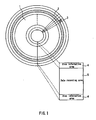
- a conventional optical disc 91 has a data recording area 95 and disc information areas 94. Parameters necessary for accessing the disc 91 are stored in the disc information areas 94.
- the disc information areas 94 are provided both on the innermost peripheral side and on the outermost peripheral side of the disc 91.
- the disc information area 94 on the innermost peripheral side is called the lead-in (lead-in) area.
- the disc information area 94 on the outermost peripheral side is called the lead-out (lead-out) area.
- PSN physical sector number
- a higher level control device (typically a host computer) issues an instruction for recording or reproduction to an optical disc device in sector units.
- the optical disc device reproduces the ECC block containing the sector from the disc and performs error correction, after which it sends back only the portion of the data that corresponds to the designated sector.
- the optical disc device reproduces the ECC block containing the sector from the disc and performs error correction, after which it substitutes recording data obtained from the higher-level control device for the portion of the data corresponding to the designated sector, re-calculates and re-assigns an error correction code to the ECC block, and records the ECC block containing the sector on the disc.
- This type of recording operation is called "read-modified write"
- the data recording area 95 contains a volume space 96 and a spare area 97.
- the volume space 96 which is an area intended for storage of user data, contains a logical volume space 96a and volume structures 96b showing the structure of the logical volume space 96a.
- LSNs logical sector numbers
- the spare area 97 contains at least one sector (substitute sector) that can be used in place of a defective sector when a defective sector is generated in the volume space 96.
- the disc information areas 94 each contain a control data area 94a and a defect management information area 94b.
- Defect management information 100 which is used for managing defective sectors, is stored within the defect management information area 94b.
- the defect management information 100 includes a disc definition structure 110, a primary defect list (hereinafter called PDL for short) 120, and a secondary defect list (hereinafter called SDL for short) 130.
- PDL primary defect list
- SDL secondary defect list
- the PDL 120 is used to manage defective sectors detected during inspection prior to shipment of the disc 91.
- the pre-shipment inspection of the disc 91 usually is performed by the manufacturer of the disc 91.
- the SDL 130 is used to manage defective sectors detected when a user uses the disc 91.
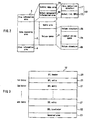
- FIG 12 shows the structure of the SDL 130.
- the SDL 130 contains a secondary defect list header (SDL header) 200 containing an identifier identifying it as an SDL, information (SDL entry number information) 210 showing the number of SDL entries 220 registered in the SDL, and one or more SDL entries 220 (in the example shown in Figure 12 , entry 1 through entry m). Note that a value of zero in the SDL entry number information 210 shows that there are no defective sectors registered in the SDL.
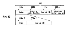
- FIG. 13 shows the structure of an SDL entry 220.
- An SDL entry 220 contains a status field 220a, a field 220b for storing information describing the location of defective sectors, and a field 220c used for storing information describing the location of substitute sectors substituted for defective sectors.
- the status field 220a is used to indicate whether substitute sectors have been substituted for defective sectors.
- the location of the defective sectors is represented, for instance, by the physical sector numbers of the defective sectors.
- the location of the substitute sectors is represented, for instance, by the physical sector numbers of the substitute sectors.
- the status field 220a contains, for instance, a 1-bit flag 220a-1 and a reserved area 220a-2. For example, a value of one in the flag 220a-1 indicates that no substitute sectors have been substituted for defective sectors. A value of zero in the flag 220a-1 indicates that a substitute sector has been substituted for a defective sector.
- defect management is performed in sector-units
- defect management also is known to be performed in block-units, with each block constituted by a plurality of sectors.
- information indicating the location of blocks (called “defective blocks") containing defective sectors (e.g., the physical sector numbers of the head sectors of the defective blocks) is registered in the SDL instead of information indicating the location of the defective sectors
- information that indicates the location of substitute blocks (for instance, the physical sector numbers of the head sectors of the substitute blocks) is registered instead of information indicating the location of the substitute sectors.
- the unit of defect management is an ECC block, i.e. the unit utilized for error correction.
- Patent Document 1 JP 2000-322836A ( Figures 1A ⁇ 1C).
- BDs a type of simplified defect inspection processing called quick certification (Quick Certincation) is possible with BDs.
- quick certification Quick Certincation
- all the entries in a defect list are inspected for defective clusters, leaving the entries intact when there are defects and invalidating the entries when there are no defects. Therefore, the more entries a defect list has, the longer the processing time becomes, requiring up to 15 minutes or so in the worst case scenario.
- the information recording device of the present invention is an information recording device for recording information on an information recording medium including a volume space for recording user data, a spare area containing a substitute area that can be used in place of a defective area contained in the volume space, and a defect management information area for recording defect management information used for managing the defective area, wherein the defect management information includes defect location information indicating the location of the defective area and defect status information indicating the status of the defective area, and an initialization processing module is provided that, during physical reformatting of the information recording medium, maintains at least the defect location information portion of the defect management information and, on the other hand, overwrites the defect status information using attributes indicating that the defective area has been physically reformatted.
- the information recording device of the present invention permits a reduction in unnecessary substitution processing after physical reformatting by maintaining at least the defect location information, without erasing it, during the physical reformatting of an information recording medium. Moreover, maintaining at least the defect location information allows for the physical reformatting to be carried out at a higher speed because conventional authentication processing is unnecessary.
- the defect management information further may include substitute location information indicating the location of the substitute area
- the initialization processing module may erase the substitute location information portion of the defect management information during the physical reformatting of the information recording medium. Because defects may be eliminated by cleaning etc. prior to and after physical reformatting, the number of unnecessary used substitute areas can be reduced by erasing substitute location information during physical reformatting.
- the defect management information further may include substitute location information indicating the location of the substitute area and the initialization processing module may be set up to maintain the substitute location information portion of the defect management information during the physical reformatting of the information recording medium.
- the inventive information recording device of the above-described configuration further includes a control module for performing at least one of recording processing and reproduction processing in an area indicated by defect location information corresponding to defect status information having the attributes and forming part of the defect management information based on the assumption that there are no significant user data.
- control module may be set up to perform recording of new user data in an area indicated by the defect location information corresponding to defect status information having the attributes and forming part of the defect management information without reproducing data from said area.
- the fact that the read processing of the read modified write operation becomes unnecessary makes it possible to avoid the problem whereby data recording is rendered impossible by the impossibility of data reproduction from the disc.
- the device may be set up such that, upon receipt of a reproduction instruction regarding areas indicated by defect location information corresponding to defect status information having the attributes and forming part of the defect management information, the control module, without reproducing data from said area, generates dummy data and uses it instead of reproducing data from said area. In this case, repetition of unnecessary reproduction attempts can be prevented by avoiding reproduction processing that is highly likely to result in errors due to defects.
- the inventive information recording device of the above-described configuration further includes a control module for performing at least one of recording processing and reproduction processing in an area indicated by defect location information corresponding to defect status information having the attributes and forming part of the defect management information based on the assumption that defects in said area may have been eliminated. Performing recording and reproduction processing on the assumption that defects may have been eliminated can reduce the number of unnecessary substitute registration operations if defects have been eliminated by cleaning etc. prior to or after physical reformatting.
- the control module invalidates the defect management information related to said area in case of success and allocates a substitute area to said area in case of failure.
- the inventive information recording device of the above-described configuration preferably erases attributes indicating that the defective area has been physically reformatted from the defect management information.
- the inventive information recording device of the above-described configuration further includes an inspection processing module for inspecting an area indicated by defect location information corresponding to defect management information having attributes indicating that physical reformatting has been performed while there are no operation instructions from a higher-level control device and invalidating the defect management information if defects in said area have been eliminated and allocating a substitute area to said area if defects in said area are confirmed.
- Disk 1 is a disc-shaped rewritable information recording medium.
- a BD is used as a specific example of the disc 1, but the disc 1 is not limited to BDs and may be a DVD-RAM, etc.
- Figure 1 shows the physical structure of the disc 1.
- a plurality of concentric or spiral tracks 2 are formed on the disc 1.
- Each one of the plurality of tracks 2 is divided into a plurality of sectors 3.
- the areas of the disc 1 include one or more disc information areas 4 and a data recording area 6.
- two disc information areas 4 are provided respectively on the innermost peripheral side and outermost peripheral side of the disc 1.
- the disc information area 4 on the innermost peripheral side also is called the lead-in dead-in) area.
- the disc information area 4 on the outermost peripheral side also is called the lead-out (lead-out) area.
- PSNs Physical sector numbers
- Figure 2 shows the logical structure of the areas of the disc 1.
- the data recording area 5 includes a volume space 6 and a spare area 7.
- the volume space 6 is an area intended for storing user data.
- logical sector numbers hereinafter called LSNs for short
- LSNs logical sector numbers
- the spare area 7 contains at least one sector that can-be used in place of a defective sector if defective sectors are present in the volume space 6.
- substitution processing on the disc 1 (BD) of the present embodiment is carried out in cluster-units, a cluster being a unit of error correction, the present invention is not limited to the above.
- the spare area 7 is located further toward the inner peripheral side of the disc 1 than the volume space 6. It is used to carry out high-speed substitution processing of clusters containing defective sectors (hereinafter called "defective clusters") when defective sectors are generated in areas storing file management information (unused space management information, root directory file entries, etc.).
- file management information unused space management information, root directory file entries, etc.
- the file management information is stored in the vicinity of sectors to which logical sector numbers of "0" are allocated. Therefore, arranging the spare area 7 further toward the inner peripheral side of the disc 1 than the volume space 6 permits a reduction in the seek distance between defective clusters and substitute clusters. As a result, the speed of substitution processing of the defective clusters is increased.
- the frequency of access to file management information is high, which is why file management information is required to have high data reliability. Therefore, high-speed substitution processing of defective clusters generated in areas storing file management information is extremely useful.
- the volume space 6 includes a logical volume space 6a and volume structures 6b, which show the structure of the logical volume space 6a.
- Unused space management information indicating whether the sectors in the logical volume space 6a are used or unused, one or more data extents where file contents are stored, and file entries, where one or more data extents corresponding to the files are registered, are stored in the logical volume space 6a. This information is used to manage files.
- the disc information areas 4 each contain a control data area 4a and a defect management information area 4b.
- Defect management information 10 used for managing clusters containing defective sectors is stored in the defect management information area 4b.
- the defect management information 10 contains a disc definition structure 11 and a defect list (hereinafter called DFL for short) 12.
- the DFL 12 is used to manage defective sectors detected during pre-shipment inspection of the disc 1 and defective sectors detected during use of the disc 1 by a user.
- the pre-shipment inspection of the disc 1 is usually performed by the manufacturer of the disc 1.
- FIG. 3 shows the structure of the DFL 12.
- the DFL 12 contains a defect list header (DFL header) 20, which indicates that this is a DFL, one or more DFL entries 21 (in the example shown in Figure 3 , entry 1 through entry m), a DFL terminator 22, which represents the end of the DFL entries, and a reserved area 23.
- DFL header defect list header
- DFL entries 21 in the example shown in Figure 3 , entry 1 through entry m
- DFL terminator 22 which represents the end of the DFL entries
- Figure 4 shows the structure of a DFL entry 21.
- a DFL entry 21 includes a first status field 21a, a first address field 21b, a second status field 21c, and a second address field 21d.
- the structure of the DFL entries is not limited to the one described above and may include other optional fields.
- the first status field 21a and second status field 21c show the attributes of said DFL entry 21, as will be described below.
- Information regarding the location of defective clusters or substitute clusters, depending on the attributes of the first status field 21a and second status field 21c, is stored in the first address field 21b and second address field 21d.
- the physical sector numbers of the head sectors of defective clusters are stored in the first address field 21b and the physical sector numbers of the head sectors of substitute clusters are stored in the second address field 21d.
- the DFL 12 in addition to the DFL entries related to clusters containing defective sectors where recording and reproduction is actually impossible, the DFL 12 also may contain DFL entries related to clusters that contained defective sectors in the past but in which defects have been eliminated by cleaning etc. during physical reformatting.
- the DFL entries 21 of the DFL 12 is not erased and is left intact during physical reformatting.
- a unique code (explained below in detail) representing the fact that said defective clusters have been physically reformatted is provided in the second status field 21c of said DFL entry 21.
- information on the location of defective clusters is stored in either one of the first address field 21b and second address field 21d, or in both fields.
- the first status field 21a may contain a 4-bit flag 21a-1 and a reserved area 21a-2.
- Figure 5A shows an example of the definition of the flag 21a-1.
- a value of 0000 in the flag 21a-1 indicates that substitute clusters have been allocated to defective clusters and the user data of the defective clusters has been recorded in the substitute clusters.
- a value of 1000 in the flag 21a-1 indicates that while substitute clusters have been allocated to the defective clusters, the user data of the defective clusters has not been recorded in the substitute clusters.
- a value of 0001 in the flag 21a-1 indicates that substitute clusters have not been allocated to defective clusters.
- a value of 0010 in the flag 21a-1 indicates that said DFL entry has been invalidated.
- the expression "has been invalidated" means that said DFL entry does not contain significant information on the location of defective clusters.
- the sector addresses designated in the second address field 21d of said DFL entry mean that clusters starting with said sectors can be utilized as future substitutes.
- a value of 0000 in the second status field 21c indicates that said field is not used, and when a value of 1000 means that clusters indicated in the first address field 21b or second address field 21d have been physically reformatted.
- This has two meanings, i.e. that the defects of clusters indicated in the first address field 21b or second address field 21d may have been eliminated by cleaning etc. during physical reformatting, and that there is no significant user data in the defective clusters and substitute clusters.
- the code 1000 of the second status field 21c is set in this field by the disc recording/reproduction drive during the physical reformatting of the disc 1.
- first status field 21a and second status field 21c shown in Figures 5A and 5B are mere examples, and the number of bits in the flags representing substitution status in the inventive information recording medium, as well as their definitions, are not limited to this example.
- Figure 6 is a block diagram showing the configuration of a disc recording and reproduction drive 1020 used in the present embodiment.
- the disc recording and reproduction drive 1020 is connected to a higher-level control device (not shown) via an I/O bus 780.
- the higher-level control device which is commonly called the host, is a device that manages recording data on the disc 1 using a file system.
- the higher-level control device and disc recording and reproduction drive 1020 can be implemented as mutually independent hardware, they of course can be implemented as a single apparatus.
- the disc recording and reproduction drive 1020 contains a microprocessor incorporating a memory used for calculation and a control program.
- the disc recording and reproduction drive 1020 which is constituted by signal processing circuitry and a mechanism controlled by the microprocessor, includes an instruction processing module 1021 for processing instructions received from the higher level control device, a recording control module 1030 for carrying out control during recording on the disc 1, a reproduction control module 1040 for carrying out control during reproduction from the disc 1, a substitute information storage memory 1050 for storing information on defective clusters and their substitute clusters, a data buffer 1060 for temporarily storing recording and reproduction data, and an initialization control module 1070 for carrying out control during the initialization of the disc 1.
- the instruction processing module 1021, recording control module 1030, reproduction control module 1040, and initialization control module 1070 are functional blocks implemented by the microprocessor running a predetermined software program.
- the instruction processing module 1021 includes a recording instruction processing module 1022 for processing recording instructions received from the higher-level control device, a reproduction instruction processing module 1024 for processing reproduction instructions received from the higher-level control device, and an initialization instruction processing module 1025 for processing initialization instructions received from the higher-level control device.
- the recording control module 1030 includes a data synthesizer module 1031 for converting recording data from sector units to cluster units, a cluster recording module 1032 for recording data on the disc 1 in cluster units, a substitute allocation module 1033 for allocating substitute clusters to defective clusters, a DFL updating module 1034 for recording the contents of the substitute information storage memory 1050 in the DFL on the disc 1, and a recordable cluster inspection module 1035 for determining the clusters in which recording is to be performed, etc.
- a data synthesizer module 1031 for converting recording data from sector units to cluster units
- a cluster recording module 1032 for recording data on the disc 1 in cluster units
- a substitute allocation module 1033 for allocating substitute clusters to defective clusters
- a DFL updating module 1034 for recording the contents of the substitute information storage memory 1050 in the DFL on the disc 1
- a recordable cluster inspection module 1035 for determining the clusters in which recording is to be performed, etc.
- the reproduction control module 1040 includes a zero-data filling module 1041 for overwriting a portion of the data buffer 1060 with zeros, a cluster reproduction module 1042 for reproducing data from the disc 1 in cluster units, a DFL reading module 1043 for storing the contents reproduced from the DFL on the disc 1 in the substitute information storage memory 1050, and a fraction correction module 1044.
- the initialization control module 1070 includes a defect management information reading module 1071 for reading defect management information 10 from the disc 1, an initialization processing module 1072 for performing the initialization processing of the defect management information 10 read from the disc 1, a defect management information updating module 1073 for writing the initialized defect management information 10 to the disc 1, and an inspection processing module 1074 for performing defect inspection (described below) of physically reformatted clusters while there are no operation instructions, such as recording instructions or reproduction instructions, from the higher-level control device.
- the processing starts when the initialization instruction processing module 1025 of the instruction processing module 1021 receives an execution instruction (initialization instruction) regarding physical reformatting from the higher-level control device.
- the initialization instruction processing module 1025 receives the instruction to execute physical reformatting, it passes the instruction on to the initialization control module 1070.
- the initialization control module 1070 first of all, reads the defect management information 10 from the defect management information area 4b of the disc 1 using the defect management information reading module 1071 and stores it in the substitute information storage memory 1050 (Step 701).
- the defect management information 10 already may be stored in the substitute information storage memory 1050, and in such a case, Step 701 may be omitted,
- the initialization processing module 1072 sets the value of the second status field 21c to 1000 in all the DFL entries 21 forming part of the defect management information 10 stored in the substitute information storage memory 1050 (Step 702).
- "1000" is a unique code indicating that the disc 1 has been physically reformatted.
- Step 703 While maintaining information representing the location of defective sectors in the DFL entries 21, the initialization processing module 1072 overwrites information representing the location of the substitute sectors in the DFL entries 21 with dummy data (Step 703). As a result, information on the location of defective sectors is maintained, while information on the location of substitute sectors is erased. However, Step 703 is not essential, and both information on the defective sectors and substitute sectors may be maintained intact.
- the defect management information updating module 1073 extracts the defect management information 10 initialized in Step 702 from the substitute information storage memory 1050 and writes it to the defect management information area 4b of the disc 1 (Step 704).
- the disc recording and reproduction drive 1020 of the present embodiment maintains at least the information on the location of defective clusters in the DFL 12. Therefore, regardless of whether defects are eliminated by cleaning etc. during physical reformatting, clusters registered in the DFL as defective clusters prior to performing the physical reformatting have information on their locations registered in the DFL as defective clusters or clusters likely to be defective even after the physical reformatting.
- the thus physically reformatted disc 1 offers the advantage of being capable of recording new data at a higher speed.
- an instruction is issued to write to clusters with DFL entries 21 in which the value of the second status field 21c is set to 1000, significant user data are not supposed to exist in the clusters as a result of physical reformatting, and therefore the disc recording and reproduction drive 1020 may limit itself to writing only the data that needs to be written without following the read-modified write procedure.
- the disc recording and reproduction drive 1020 may attempt to access the clusters of the disc 1 and reproduce them or may be set up to return dummy data instead of the reproduction data from the disc 1 without checking whether said clusters can be reproduced or not. Otherwise, if an attempt at reproducing the clusters is made and it is found that they can be reproduced at least partially, results obtained by performing correction within the correctable range can be used as reproduction data.
- reproduction of ordinary computer data recorded on the disc 1 (not real-time data) is used as an example in order to explain the reproduction method utilized by the disc recording and reproduction drive 1020.
- Figure 8 shows the steps of the reproduction method.
- the reference numeral 111 indicates processing executed by the higher-level control device
- the reference numeral 112 indicates processing executed by the disc recording and reproduction drive 1020
- the reference numeral 113 indicates the flow of instructions, data, and processing results based on the I/F protocol between the higher-level control device and the disc recording and reproduction drive 1020.
- reproduction processing by the disc recording and reproduction drive 1020 will be described in detail below, explanations here will be provided only in general terms.
- the disc recording and reproduction drive 1020 reads the defect management information on the disc 1 using the DFL reading module 1043 and stores it in the substitute information storage memory 1050 (step 1101).
- the higher-level control device analyzes the file structure and obtains the location of the areas where computer data is stored (Step 1102).
- the higher-level control device acquires information indicating the location of the areas obtained in Step 1102 and issues a "READ" command, i.e. an ordinary reproduction instruction, to the disc recording and reproduction drive 1020 (Step 1103).
- a "READ" command i.e. an ordinary reproduction instruction
- the reproduction instruction processing module 1024 of the disc recording and reproduction drive 1020 that receives the "READ" command reads the designated data from the disc 1 (Step 1104), transfers the designated data to the higher-level control device (Step 1105) and, when the transfer of all the required data is complete, returns an end status code (Step 1107).
- Playback data transferred via the I/F protocol is stored in the data buffer memory of the higher-level control device (Step 1106).
- data stored in the data buffer memory is used as computer data.
- Figure 9 is a flow chart showing the details of the reproduction processing procedure (Step 1104 in Figure 8 ) executed by the disc recording and reproduction drive 1020.
- the areas to be reproduced are designated by the higher-level control device in sector units.
- the fraction correction module 1044 obtains clusters containing the sectors to be reproduced (Step 1201). If the LSN of the head sectors in areas to be reproduced is designated as S, the number of sectors in the areas to be reproduced as N, and the number of sectors that constitute clusters as E, then the number of sectors (N_C) in the areas to be reproduced and LSN (S_C) of the head sectors in the areas to be reproduced, with clusters taken into account, is given by the following formulas.
- Step 1202 If the process of storing all the clusters intended for reproduction in the data buffer 1060 is not over (Step 1202), the program consults the DFL 12 (Step 1203). As a result, when the clusters intended for reproduction are not registered in the DFL 12 as defective clusters, processing advances to Step 1204 and the cluster reproduction module 1042 reproduces the clusters obtained in Step 1201 and stores them in the data buffer 1060 (Step 1204). On the other hand, when the clusters to be reproduced are registered in the DFL 12 as defective clusters, processing advances to Step 1205.
- Step 1205 the cluster reproduction module 1042 refers to the second status field 21c and first status field 21a of the DFL entries 21 of the clusters (defective clusters) to be reproduced and advances to either one of Steps 1206-1208 below depending on the values.
- Step 1206 the cluster reproduction module 1042 reproduces data from the substitute spare clusters and stores it in the data buffer 1060.
- Step 1207 the cluster reproduction module 1041 attempts reproduction of data from the replaced clusters, storing the data in the data buffer 1060 if it is successful and reporting an error in case of failure.
- clusters in which the value of the second status field 21c is 1000 are clusters initialized by physical reformatting.
- Step 1208 when the value of the second status field 21c is 1000, dummy data are generated in Step 1208.
- an attempt may be made to reproduce the defective clusters on the disc 1, storing the data that were reproduced in the data buffer 1060 when the reproduction is successful and using the data buffer 1060 to store dummy data produced by zero-filling etc. in case of failure or, in case of partial reproduction, using it to store data that can be obtained from the reproduction data by correction.
- Step 1202 When the process of storing all the clusters to be reproduced in the data buffer 1060 is over ("Yes" in Step 1202), the data stored in the data buffer 1060 is transferred to the higher-level control device via the I/O bus 780 and the process terminates.
- the higher-level control device issues an instruction to perform recording in said clusters- Therefore, substitution processing is carried out, wherein spare clusters are allocated thereto and data is recorded in the allocated spare clusters. As a result, spare clusters that can be reproduced are substituted for defective clusters in the logical volume space.
- the disc recording and reproduction drive 1020 returns zero-filled data as reproduction data without reporting reproduction errors. Otherwise, when defective blocks to which substitute spare clusters have not been allocated need to be reproduced, it may be set up to report a reproduction error without wasting time on unnecessary reproduction operations that are likely to fail.
- Figure 10 is a flow chart showing the sequence of recording processing executed by the disc recording and reproduction drive 1020.
- the disc recording and reproduction drive 1020 receives data to be recorded on the disc 1 from the higher-level control device and stores it in the data buffer 1060 (Step 1301).
- the areas where recording needs to be done are designated in sector units.
- the recordable cluster inspection module 1035 determines the clusters (clusters to be recorded) that include areas where recording is required (Step 1302).
- Step 1304 the device checks whether the cluster containing the head sector has been registered as a DFL entry with attributes indicative of physical reformatting (the second status field 21c is 1000) (Step 1304). If it has been registered, reproduction processing intended for the buffering processing of the cluster is not performed, and the data buffer 1060 is instead filled with dummy data (Step 1305). If it has not been registered, reproduction processing intended for buffering processing is carried out (Step 1306).
- Step 1307 the device checks whether the cluster containing the end sector has been registered as a DFL entry with attributes indicative of physical reformatting (Step 1308). If it has been registered, reproduction processing intended for the buffering processing of the cluster is not performed, and the data buffer 1060 is instead filled with dummy data (Step 1309). If it has not been registered, reproduction processing intended for buffering processing is carried out (Step 1310).
- data used for recording is synthesized by overwriting the location corresponding to said sector in the data buffer 1060 with data transferred from the host (Step 1311).
- Step 1312 If the clusters to be recorded have been registered as DFL entries possessing attributes indicative of physical reformatting ("Yes” in Step 1312), recording is carried out in the clusters shown as defective clusters in said DFL entries regardless of whether substitutes have been allocated (Step 1313).
- Step 13175 if the clusters to be recorded have not been registered as DFL entries possessing attributes indicative of physical reformatting ("No" in Step 1312), recording is carried out in substitute spare clusters (Step 1315) if substitutes have been allocated ("Yes” in Step 1314). In addition, if substitutes have not been allocated ("No” in Step 1314), after allocating new substitute spare clusters, recording is carried out in the substitute spare clusters (Step 1316).
- the codes in the first status field 21a of the DFL entries are set in accordance with the circumstances and the contents of the second status field 21c are changed from 1000 to 0000.
- the disc recording and reproduction drive 1020 of the present embodiment has a feature whereby it inspects areas shown as defective areas in DFL entries possessing attributes indicative of physical reformatting while no operation instructions are issued by the higher-level control device (or during idle time in the course of other processing). Namely, while there are no operation instructions, such as recording instructions or reproduction instructions, issued by the higher-level control device, the inspection processing module 1074 searches all the DFL entries 21 registered in the DFL 12 and examines clusters shown as defective clusters in the DFL entries 21 with "1000" in the second status field 21c in order to determine whether they are indeed defective. Then, if defects have been eliminated in said clusters, the inspection processing module 1074 invalidates said DFL entries 21 by setting the first status field 21a to 0010.
- the inspection processing module 1074 allocates substitute areas to said clusters and, at the same time, sets the first status field 21a to 0000 or 1000 and changes the contents of the second status field 21c from 1000 to 0000.
- the time period during which there are no operation instructions issued by the higher-level control device permits efficient inspection of defects on the physically reformatted disc.
- a value of 1000 in the second status field 21c implied that clusters shown in the field 21b had been physically reformatted, in other words, it represented two meanings, i.e. (1) that the defects of the clusters shown in the field 21b could have been eliminated by cleaning etc. during physical reformatting, and (2) that no significant user data were present in the defective clusters and in the substitute clusters.
- the above-mentioned items (1) and (2) may be assigned individual codes for each respective meaning so as to perform mutually different recording and reproduction processing depending on the respective code.
- the disc 1 was exemplified by a BD in the present embodiment
- the present invention is similarly applicable to information recording media, in which a single unit of error correction is constituted by a plurality of sectors, such as a DVD.
- a single unit of error correction is constituted by a plurality of sectors, such as a DVD.
- ECC blocks in case of a DVD locations described as “clusters" in the present embodiment can be called "ECC blocks".
- data transfer between the higher-level control device and the disc recording and reproduction drive, as well as data transfer between the disc recording and reproduction device and the disc can be carried out either sequentially or simultaneously in parallel.
- parameter transfer can be implemented using a shared memory, etc.
Description
- The present invention relates to an information recording device for recording and reproducing information on optical discs and other information recording media.
- In recent years, DVDs have gained widespread acceptance as optical discs permitting the recording of moving picture images in the form of digital information. In addition, Blu-ray discs (hereinafter called "BD" for short), which are known as the next-generation optical discs capable of recording at even higher densities than DVDs, already have reached the deployment stage.
-
US 2003/210627 discloses an initialization technique for an informatted recording medium which includes a defect management area with defect location and status information. - In case of DVDs, BDs and other optical discs, the minimum unit of logical access is called a sector. In the past, when a DVD-RAM or a BD had sectors where information could not be recorded or reproduced (called "defective sectors"), the reliability of recording data was ensured by performing the so-called defect management, whereby ECC blocks (in case of a DVD) or clusters (in case of a BD) in good condition were substituted for ECC blocks or clusters containing defective sectors. Defective sectors are generated not only during disc manufacture, but also as a result of scratches, contamination, and the like, adhering to the surface of discs when discs are in use.
- An example of a conventional optical disc where such defect management is performed, as well as an apparatus for its recording and reproduction, are disclosed in
Patent Document 1. Here, explanations will be provided regarding the conventional optical disc (DVD) disclosed inPatent Document 1. - As shown in
Figure 11 , a conventionaloptical disc 91 has adata recording area 95 anddisc information areas 94. Parameters necessary for accessing thedisc 91 are stored in thedisc information areas 94. In this example, thedisc information areas 94 are provided both on the innermost peripheral side and on the outermost peripheral side of thedisc 91. Thedisc information area 94 on the innermost peripheral side is called the lead-in (lead-in) area. Thedisc information area 94 on the outermost peripheral side is called the lead-out (lead-out) area. - The recording and reproduction of data is performed in the
data recording area 95. An absolute address called a physical sector number (hereinafter called PSN for short) is allocated in advance to each of the sectors of thedata recording area 95. - A higher level control device (typically a host computer) issues an instruction for recording or reproduction to an optical disc device in sector units. When an instruction is issued by the higher-level control device to perform reproduction of a certain sector, the optical disc device reproduces the ECC block containing the sector from the disc and performs error correction, after which it sends back only the portion of the data that corresponds to the designated sector. In addition, when an instruction is issued by the higher-level control device to perform recording in a certain sector, the optical disc device reproduces the ECC block containing the sector from the disc and performs error correction, after which it substitutes recording data obtained from the higher-level control device for the portion of the data corresponding to the designated sector, re-calculates and re-assigns an error correction code to the ECC block, and records the ECC block containing the sector on the disc. This type of recording operation is called "read-modified write"
- The
data recording area 95 contains avolume space 96 and aspare area 97. Thevolume space 96, which is an area intended for storage of user data, contains alogical volume space 96a andvolume structures 96b showing the structure of thelogical volume space 96a. To provide access to thevolume space 96, logical sector numbers (hereinafter called LSNs for short) are allocated to the sectors contained in thevolume space 96. Data recording and reproduction is performed by accessing sectors on thedisc 91 using the LSNs. - The
spare area 97 contains at least one sector (substitute sector) that can be used in place of a defective sector when a defective sector is generated in thevolume space 96. - The
disc information areas 94 each contain acontrol data area 94a and a defectmanagement information area 94b.Defect management information 100, which is used for managing defective sectors, is stored within the defectmanagement information area 94b. - The
defect management information 100 includes adisc definition structure 110, a primary defect list (hereinafter called PDL for short) 120, and a secondary defect list (hereinafter called SDL for short) 130. - The PDL 120 is used to manage defective sectors detected during inspection prior to shipment of the
disc 91. The pre-shipment inspection of thedisc 91 usually is performed by the manufacturer of thedisc 91. The SDL 130 is used to manage defective sectors detected when a user uses thedisc 91. -
Figure 12 shows the structure of theSDL 130. TheSDL 130 contains a secondary defect list header (SDL header) 200 containing an identifier identifying it as an SDL, information (SDL entry number information) 210 showing the number ofSDL entries 220 registered in the SDL, and one or more SDL entries 220 (in the example shown inFigure 12 ,entry 1 through entry m). Note that a value of zero in the SDLentry number information 210 shows that there are no defective sectors registered in the SDL. -
Figure 13 shows the structure of anSDL entry 220. AnSDL entry 220 contains astatus field 220a, afield 220b for storing information describing the location of defective sectors, and a field 220c used for storing information describing the location of substitute sectors substituted for defective sectors. - The
status field 220a is used to indicate whether substitute sectors have been substituted for defective sectors. The location of the defective sectors is represented, for instance, by the physical sector numbers of the defective sectors. The location of the substitute sectors is represented, for instance, by the physical sector numbers of the substitute sectors. - The
status field 220a contains, for instance, a 1-bit flag 220a-1 and areserved area 220a-2. For example, a value of one in theflag 220a-1 indicates that no substitute sectors have been substituted for defective sectors. A value of zero in theflag 220a-1 indicates that a substitute sector has been substituted for a defective sector. - Although the above-explanations assume that defect management is performed in sector-units, defect management also is known to be performed in block-units, with each block constituted by a plurality of sectors. In such a case, information indicating the location of blocks (called "defective blocks") containing defective sectors (e.g., the physical sector numbers of the head sectors of the defective blocks) is registered in the SDL instead of information indicating the location of the defective sectors, and information that indicates the location of substitute blocks (for instance, the physical sector numbers of the head sectors of the substitute blocks) is registered instead of information indicating the location of the substitute sectors. For instance, in the case of a DVD, the unit of defect management is an ECC block, i.e. the unit utilized for error correction.
- Incidentally, when the number of defective sectors increases, the frequency of substitute sector accesses becomes higher, thereby severely decreasing the speed of recording and reproduction and creating a particularly serious hindrance to the recording and reproduction of moving pictures. In addition, since substitute sectors are secured in the
data recording area 95, when numerous substitute areas are secured as a result of increased frequency of substitution, the recordable volume of user data is reduced as well. In such a case, physical reformatting (re-initialization) is recommended after cleaning the disc to remove dirt adhered to the surface of the disc. Subsequently created defects mostly are due to, for example, fingerprints on the disc surface, and most of the subsequently created defects are eliminated by cleaning. - Conventionally, when physical reformatting was performed, all the contents of the
status field 220a,field 220b and field 220c in theSDL entry 220 were invalidated - In addition, the conventional technology described in
Patent Document 1 relates mostly to DVDs, and in case of BDs, all the contents of the defect list are erased when physical reformatting is carried out.
Patent Document1:JP 2000-322836A - However, in the past, the erasure of the entire contents of the defect list resulted in the following problems.
- Namely, because all of the contents of the defect list were erased during physical reformatting, information indicating the location of defective sectors (or sectors where defects could be present) also was lost. Therefore, when there were defects that disc surface cleaning did not eliminate, recording of new data on the disc after formatting could result in user data being recorded despite the possible presence of defects, which required reproduction to be performed for read-modified write. However, reproduction was impossible because of the defects, and, as a result, recording was impossible as well.
- In addition, in the past, devices have been known that, after performing physical reformatting, optionally perform defect inspection processing (certification) by checking all the sectors on the disc for the presence of defects and registering information on the discovered defective sectors in a defect list.
- As an example of such conventional authentication processing, a technique is known in which authentication data is written over the entire volume space of the disc and the presence of defects on the disc is determined by confirming whether or not the written data can be reproduced correctly. However, the problem with this method is that, in the case of a DVD, for instance, authentication processing requires close to one hour from start to finish, which is extremely inconvenient for the user.
- In addition, a type of simplified defect inspection processing called quick certification (Quick Certincation) is possible with BDs. During such processing, all the entries in a defect list are inspected for defective clusters, leaving the entries intact when there are defects and invalidating the entries when there are no defects. Therefore, the more entries a defect list has, the longer the processing time becomes, requiring up to 15 minutes or so in the worst case scenario.
- Taking into account the above-described problems, it is an object of the present invention to provide an information recording device capable of high-speed physical reformatting while avoiding unnecessary substitution processing after physical reformatting.
- In order to attain the above-mentioned object, the information recording device of the present invention is an information recording device for recording information on an information recording medium including a volume space for recording user data, a spare area containing a substitute area that can be used in place of a defective area contained in the volume space, and a defect management information area for recording defect management information used for managing the defective area, wherein the defect management information includes defect location information indicating the location of the defective area and defect status information indicating the status of the defective area, and an initialization processing module is provided that, during physical reformatting of the information recording medium, maintains at least the defect location information portion of the defect management information and, on the other hand, overwrites the defect status information using attributes indicating that the defective area has been physically reformatted.
- The information recording device of the present invention permits a reduction in unnecessary substitution processing after physical reformatting by maintaining at least the defect location information, without erasing it, during the physical reformatting of an information recording medium. Moreover, maintaining at least the defect location information allows for the physical reformatting to be carried out at a higher speed because conventional authentication processing is unnecessary.
-
- [
FIG. 1] Figure 1 is an explanatory figure showing the structure of a recording area of an information recording medium according to an embodiment of the present invention. - [
FIG. 2] Figure 2 is an explanatory figure showing the logical structure of a recording area in an information recording medium according to an embodiment of the present invention. - [
FIG. 3] Figure 3 is a diagram showing the structure of theDFL 12 shown inFigure 2 . - [
FIG. 4] Figure 4 is a diagram showing the structure of aDFL entry 21 in theDFL 12. - [
FIG. 5A] Figure 5A is a diagram showing an example of the definition of afirst status field 21a in aDFL entry 21. - [
FIG. 5B] Figure 5B is a diagram showing an example of the definition of asecond status field 21c in aDFL entry 21. - [
FIG. 6] Figure 6 is a block diagram showing the configuration of a disc recording andreproduction drive 1020 according to an embodiment of the present invention. - [
FIG. 7] Figure 7 is a flow chart showing the procedure of physical reformatting processing executed by the disc recording andreproduction drive 1020. - [
FIG. 8] Figure 8 is a flow chart showing the procedure of reproduction processing executed by the disc recording andreproduction drive 1020. - [
FIG. 9] Figure 9 is a flow chart showing the details of the reproduction processing procedure executed by the disc recording andreproduction drive 1020. - [
FIG. 10] Figure 10 is a flow chart showing the procedure of recording processing executed by the disc recording andreproduction drive 1020. - [
FIG. 11] Figure 11 is an explanatory figure showing an example of the logical structure of a recording area in a conventional information recording medium. - [
FIG. 12] Figure 12 is a diagram showing an example of a defect list in a conventional information recording medium. - [
FIG. 13] Figure 13 is a diagram showing the structure of SDL entries in the conventional defect list ofFigure 12 . - In the inventive information recording device of the above-described configuration, the defect management information further may include substitute location information indicating the location of the substitute area, and the initialization processing module may erase the substitute location information portion of the defect management information during the physical reformatting of the information recording medium. Because defects may be eliminated by cleaning etc. prior to and after physical reformatting, the number of unnecessary used substitute areas can be reduced by erasing substitute location information during physical reformatting.
- In the inventive information recording device of the above-described configuration, the defect management information further may include substitute location information indicating the location of the substitute area and the initialization processing module may be set up to maintain the substitute location information portion of the defect management information during the physical reformatting of the information recording medium. As a result, substitute registration can be carried out at a high speed, because when recording is about to be performed in an area indicated by the defect location information and said area is defective, processing involving searching for and re-allocating an unused area among the substitute areas is unnecessary.
- It is preferable that the inventive information recording device of the above-described configuration further includes a control module for performing at least one of recording processing and reproduction processing in an area indicated by defect location information corresponding to defect status information having the attributes and forming part of the defect management information based on the assumption that there are no significant user data.
- For instance, the control module may be set up to perform recording of new user data in an area indicated by the defect location information corresponding to defect status information having the attributes and forming part of the defect management information without reproducing data from said area. In this case, the fact that the read processing of the read modified write operation becomes unnecessary makes it possible to avoid the problem whereby data recording is rendered impossible by the impossibility of data reproduction from the disc.
- Otherwise, the device may be set up such that, upon receipt of a reproduction instruction regarding areas indicated by defect location information corresponding to defect status information having the attributes and forming part of the defect management information, the control module, without reproducing data from said area, generates dummy data and uses it instead of reproducing data from said area. In this case, repetition of unnecessary reproduction attempts can be prevented by avoiding reproduction processing that is highly likely to result in errors due to defects.
- It is preferable that the inventive information recording device of the above-described configuration further includes a control module for performing at least one of recording processing and reproduction processing in an area indicated by defect location information corresponding to defect status information having the attributes and forming part of the defect management information based on the assumption that defects in said area may have been eliminated. Performing recording and reproduction processing on the assumption that defects may have been eliminated can reduce the number of unnecessary substitute registration operations if defects have been eliminated by cleaning etc. prior to or after physical reformatting.
- For instance, it is preferable that after performing trial recording of data in an area indicated by defect location information corresponding to defect status information having the attributes and forming part of the defect management information, the control module invalidates the defect management information related to said area in case of success and allocates a substitute area to said area in case of failure. This offers the advantage of being able to reduce the number of unnecessary substitute registration operations.
- In addition, when user data is recorded in a defective area indicated by the defect location information forming part of the defect management information or when a substitute area is substituted for the defective area in the course of substitution processing, the inventive information recording device of the above-described configuration preferably erases attributes indicating that the defective area has been physically reformatted from the defect management information.
- In addition, it is preferable that the inventive information recording device of the above-described configuration further includes an inspection processing module for inspecting an area indicated by defect location information corresponding to defect management information having attributes indicating that physical reformatting has been performed while there are no operation instructions from a higher-level control device and invalidating the defect management information if defects in said area have been eliminated and allocating a substitute area to said area if defects in said area are confirmed.
- A specific embodiment of the present invention is explained below by referring to drawings.
- In the present embodiment,
Disk 1 is a disc-shaped rewritable information recording medium. Here, a BD is used as a specific example of thedisc 1, but thedisc 1 is not limited to BDs and may be a DVD-RAM, etc. -
Figure 1 shows the physical structure of thedisc 1. A plurality of concentric orspiral tracks 2 are formed on thedisc 1. Each one of the plurality oftracks 2 is divided into a plurality of sectors 3. The areas of thedisc 1 include one or moredisc information areas 4 and a data recording area 6. In the example ofFigure 1 , twodisc information areas 4 are provided respectively on the innermost peripheral side and outermost peripheral side of thedisc 1. Thedisc information area 4 on the innermost peripheral side also is called the lead-in dead-in) area. Thedisc information area 4 on the outermost peripheral side also is called the lead-out (lead-out) area. - The recording and reproduction of data is carried out in the
data recording area 5. Absolute addresses called physical sector numbers (hereinafter called PSNs for short) are allocated to all the sectors of thedata recording area 5 in advance. -
Figure 2 shows the logical structure of the areas of thedisc 1. - The
data recording area 5 includes a volume space 6 and a spare area 7. The volume space 6 is an area intended for storing user data. To access the volume space 6, logical sector numbers (hereinafter called LSNs for short) are allocated to the sectors contained in the volume space 6. The recording and reproduction of data is carried out by accessing sectors on thedisc 1 using their LSNs. - The spare area 7 contains at least one sector that can-be used in place of a defective sector if defective sectors are present in the volume space 6. In addition, while the following explanations assume that substitution processing on the disc 1 (BD) of the present embodiment is carried out in cluster-units, a cluster being a unit of error correction, the present invention is not limited to the above.
- The spare area 7 is located further toward the inner peripheral side of the
disc 1 than the volume space 6. It is used to carry out high-speed substitution processing of clusters containing defective sectors (hereinafter called "defective clusters") when defective sectors are generated in areas storing file management information (unused space management information, root directory file entries, etc.). The file management information is stored in the vicinity of sectors to which logical sector numbers of "0" are allocated. Therefore, arranging the spare area 7 further toward the inner peripheral side of thedisc 1 than the volume space 6 permits a reduction in the seek distance between defective clusters and substitute clusters. As a result, the speed of substitution processing of the defective clusters is increased. The frequency of access to file management information is high, which is why file management information is required to have high data reliability. Therefore, high-speed substitution processing of defective clusters generated in areas storing file management information is extremely useful. - The volume space 6 includes a
logical volume space 6a and volume structures 6b, which show the structure of thelogical volume space 6a. Unused space management information indicating whether the sectors in thelogical volume space 6a are used or unused, one or more data extents where file contents are stored, and file entries, where one or more data extents corresponding to the files are registered, are stored in thelogical volume space 6a. This information is used to manage files. - The
disc information areas 4 each contain acontrol data area 4a and a defectmanagement information area 4b.Defect management information 10 used for managing clusters containing defective sectors is stored in the defectmanagement information area 4b. - The
defect management information 10 contains a disc definition structure 11 and a defect list (hereinafter called DFL for short) 12. - The
DFL 12 is used to manage defective sectors detected during pre-shipment inspection of thedisc 1 and defective sectors detected during use of thedisc 1 by a user. In addition, the pre-shipment inspection of thedisc 1 is usually performed by the manufacturer of thedisc 1. -
Figure 3 shows the structure of theDFL 12. - The
DFL 12 contains a defect list header (DFL header) 20, which indicates that this is a DFL, one or more DFL entries 21 (in the example shown inFigure 3 ,entry 1 through entry m), aDFL terminator 22, which represents the end of the DFL entries, and a reservedarea 23. -
Figure 4 shows the structure of aDFL entry 21. - A
DFL entry 21 includes afirst status field 21a, afirst address field 21b, asecond status field 21c, and asecond address field 21d. In addition, the structure of the DFL entries is not limited to the one described above and may include other optional fields. - The
first status field 21a andsecond status field 21c show the attributes of saidDFL entry 21, as will be described below. Information regarding the location of defective clusters or substitute clusters, depending on the attributes of thefirst status field 21a andsecond status field 21c, is stored in thefirst address field 21b andsecond address field 21d. For instance, in some cases, the physical sector numbers of the head sectors of defective clusters are stored in thefirst address field 21b and the physical sector numbers of the head sectors of substitute clusters are stored in thesecond address field 21d. - In the present embodiment, in addition to the DFL entries related to clusters containing defective sectors where recording and reproduction is actually impossible, the
DFL 12 also may contain DFL entries related to clusters that contained defective sectors in the past but in which defects have been eliminated by cleaning etc. during physical reformatting. In other words, while all of the information related to defective clusters used to be erased when physical reformatting was performed in the past, in the present embodiment, at least information on the location of defective clusters in all theDFL entries 21 of theDFL 12 is not erased and is left intact during physical reformatting. In addition, a unique code (explained below in detail) representing the fact that said defective clusters have been physically reformatted is provided in thesecond status field 21c of saidDFL entry 21. In addition, information on the location of defective clusters is stored in either one of thefirst address field 21b andsecond address field 21d, or in both fields. - The
first status field 21a may contain a 4-bit flag 21a-1 and areserved area 21a-2.Figure 5A shows an example of the definition of theflag 21a-1. For example, a value of 0000 in theflag 21a-1 indicates that substitute clusters have been allocated to defective clusters and the user data of the defective clusters has been recorded in the substitute clusters. In addition, a value of 1000 in theflag 21a-1 indicates that while substitute clusters have been allocated to the defective clusters, the user data of the defective clusters has not been recorded in the substitute clusters. In addition, a value of 0001 in theflag 21a-1 indicates that substitute clusters have not been allocated to defective clusters. Furthermore, a value of 0010 in theflag 21a-1 indicates that said DFL entry has been invalidated. The expression "has been invalidated" means that said DFL entry does not contain significant information on the location of defective clusters. However, the sector addresses designated in thesecond address field 21d of said DFL entry mean that clusters starting with said sectors can be utilized as future substitutes. - As shown in
Figure 5B , a value of 0000 in thesecond status field 21c indicates that said field is not used, and when a value of 1000 means that clusters indicated in thefirst address field 21b orsecond address field 21d have been physically reformatted. This has two meanings, i.e. that the defects of clusters indicated in thefirst address field 21b orsecond address field 21d may have been eliminated by cleaning etc. during physical reformatting, and that there is no significant user data in the defective clusters and substitute clusters. - While the above-described codes of the
first status field 21a, i.e. 0000, 0001, 1000, etc., are set depending on the substitution status during the recording and reproduction of thedisc 1, thecode 1000 of thesecond status field 21c, as will be described below, is set in this field by the disc recording/reproduction drive during the physical reformatting of thedisc 1. - In addition, the definitions of the
first status field 21a andsecond status field 21c shown inFigures 5A and 5B are mere examples, and the number of bits in the flags representing substitution status in the inventive information recording medium, as well as their definitions, are not limited to this example. - An embodiment of an information recording and reproduction device corresponding to the above-described
disc 1 is explained below by referring to drawings. -
Figure 6 is a block diagram showing the configuration of a disc recording andreproduction drive 1020 used in the present embodiment. The disc recording andreproduction drive 1020 is connected to a higher-level control device (not shown) via an I/O bus 780. The higher-level control device, which is commonly called the host, is a device that manages recording data on thedisc 1 using a file system. In addition, while the higher-level control device and disc recording andreproduction drive 1020 can be implemented as mutually independent hardware, they of course can be implemented as a single apparatus. - The disc recording and
reproduction drive 1020 contains a microprocessor incorporating a memory used for calculation and a control program. The disc recording andreproduction drive 1020, which is constituted by signal processing circuitry and a mechanism controlled by the microprocessor, includes aninstruction processing module 1021 for processing instructions received from the higher level control device, arecording control module 1030 for carrying out control during recording on thedisc 1, areproduction control module 1040 for carrying out control during reproduction from thedisc 1, a substituteinformation storage memory 1050 for storing information on defective clusters and their substitute clusters, adata buffer 1060 for temporarily storing recording and reproduction data, and aninitialization control module 1070 for carrying out control during the initialization of thedisc 1. Theinstruction processing module 1021,recording control module 1030,reproduction control module 1040, andinitialization control module 1070 are functional blocks implemented by the microprocessor running a predetermined software program. - The
instruction processing module 1021 includes a recordinginstruction processing module 1022 for processing recording instructions received from the higher-level control device, a reproductioninstruction processing module 1024 for processing reproduction instructions received from the higher-level control device, and an initializationinstruction processing module 1025 for processing initialization instructions received from the higher-level control device. - The
recording control module 1030 includes adata synthesizer module 1031 for converting recording data from sector units to cluster units, acluster recording module 1032 for recording data on thedisc 1 in cluster units, asubstitute allocation module 1033 for allocating substitute clusters to defective clusters, aDFL updating module 1034 for recording the contents of the substituteinformation storage memory 1050 in the DFL on thedisc 1, and a recordablecluster inspection module 1035 for determining the clusters in which recording is to be performed, etc. - The
reproduction control module 1040 includes a zero-data filling module 1041 for overwriting a portion of thedata buffer 1060 with zeros, acluster reproduction module 1042 for reproducing data from thedisc 1 in cluster units, aDFL reading module 1043 for storing the contents reproduced from the DFL on thedisc 1 in the substituteinformation storage memory 1050, and afraction correction module 1044. - The
initialization control module 1070 includes a defect managementinformation reading module 1071 for readingdefect management information 10 from thedisc 1, aninitialization processing module 1072 for performing the initialization processing of thedefect management information 10 read from thedisc 1, a defect managementinformation updating module 1073 for writing the initializeddefect management information 10 to thedisc 1, and aninspection processing module 1074 for performing defect inspection (described below) of physically reformatted clusters while there are no operation instructions, such as recording instructions or reproduction instructions, from the higher-level control device. - The operation of the disc recording and
reproduction drive 1020 shown inFigure 6 is described below. - First of all, the process of physical reformatting of the
disc 1 by the disc recording andreproduction drive 1020 will be explained by referring toFigure 7 . - The processing starts when the initialization
instruction processing module 1025 of theinstruction processing module 1021 receives an execution instruction (initialization instruction) regarding physical reformatting from the higher-level control device. When the initializationinstruction processing module 1025 receives the instruction to execute physical reformatting, it passes the instruction on to theinitialization control module 1070. Theinitialization control module 1070, first of all, reads thedefect management information 10 from the defectmanagement information area 4b of thedisc 1 using the defect managementinformation reading module 1071 and stores it in the substitute information storage memory 1050 (Step 701). In addition, thedefect management information 10 already may be stored in the substituteinformation storage memory 1050, and in such a case,Step 701 may be omitted, - Next, the
initialization processing module 1072 sets the value of thesecond status field 21c to 1000 in all theDFL entries 21 forming part of thedefect management information 10 stored in the substitute information storage memory 1050 (Step 702). In addition, as shown inFigure 5B , "1000" is a unique code indicating that thedisc 1 has been physically reformatted. - While maintaining information representing the location of defective sectors in the
DFL entries 21, theinitialization processing module 1072 overwrites information representing the location of the substitute sectors in theDFL entries 21 with dummy data (Step 703). As a result, information on the location of defective sectors is maintained, while information on the location of substitute sectors is erased. However,Step 703 is not essential, and both information on the defective sectors and substitute sectors may be maintained intact. - Next, the defect management
information updating module 1073 extracts thedefect management information 10 initialized inStep 702 from the substituteinformation storage memory 1050 and writes it to the defectmanagement information area 4b of the disc 1 (Step 704). - As a result of the above-described processing, during the physical reformatting of the
disc 1, the disc recording andreproduction drive 1020 of the present embodiment maintains at least the information on the location of defective clusters in theDFL 12. Therefore, regardless of whether defects are eliminated by cleaning etc. during physical reformatting, clusters registered in the DFL as defective clusters prior to performing the physical reformatting have information on their locations registered in the DFL as defective clusters or clusters likely to be defective even after the physical reformatting. - In comparison with conventional discs, the thus physically reformatted
disc 1 offers the advantage of being capable of recording new data at a higher speed. When an instruction is issued to write to clusters withDFL entries 21 in which the value of thesecond status field 21c is set to 1000, significant user data are not supposed to exist in the clusters as a result of physical reformatting, and therefore the disc recording andreproduction drive 1020 may limit itself to writing only the data that needs to be written without following the read-modified write procedure. - Furthermore, because it is possible that defects may have been eliminated by cleaning etc. during physical reformatting, when an instruction is issued to write to said clusters, a trial attempt may be made to write to said clusters. In this case, when the write attempt is successful, it is determined that defects in said clusters have been eliminated, and therefore the DFL entries for said clusters may be invalidated. The invalidation of the DFL entries is carried out by setting the value of the
first status field 21a of said DFL entries to 0010. In addition, if the write attempt fails, it is determined that defects in said clusters have not been eliminated, and therefore spare clusters may be allocated thereto as substitutes and write operations may be performed in the allocated spare clusters as performed in the past. - In addition, when an instruction is issued to read clusters with DFL entries in which the value of the
second status field 21c is set to 1000, the disc recording andreproduction drive 1020 may attempt to access the clusters of thedisc 1 and reproduce them or may be set up to return dummy data instead of the reproduction data from thedisc 1 without checking whether said clusters can be reproduced or not. Otherwise, if an attempt at reproducing the clusters is made and it is found that they can be reproduced at least partially, results obtained by performing correction within the correctable range can be used as reproduction data. - Here, reproduction of ordinary computer data recorded on the disc 1 (not real-time data) is used as an example in order to explain the reproduction method utilized by the disc recording and
reproduction drive 1020. -
Figure 8 shows the steps of the reproduction method. - In
Figure 8 , thereference numeral 111 indicates processing executed by the higher-level control device, thereference numeral 112 indicates processing executed by the disc recording andreproduction drive 1020, and thereference numeral 113 indicates the flow of instructions, data, and processing results based on the I/F protocol between the higher-level control device and the disc recording andreproduction drive 1020. In addition, since reproduction processing by the disc recording andreproduction drive 1020 will be described in detail below, explanations here will be provided only in general terms. - When the
disc 1 is mounted and when the defect management information is updated, the disc recording andreproduction drive 1020 reads the defect management information on thedisc 1 using theDFL reading module 1043 and stores it in the substitute information storage memory 1050 (step 1101). - The higher-level control device analyzes the file structure and obtains the location of the areas where computer data is stored (Step 1102).
- The higher-level control device acquires information indicating the location of the areas obtained in
Step 1102 and issues a "READ" command, i.e. an ordinary reproduction instruction, to the disc recording and reproduction drive 1020 (Step 1103). - The reproduction
instruction processing module 1024 of the disc recording andreproduction drive 1020 that receives the "READ" command reads the designated data from the disc 1 (Step 1104), transfers the designated data to the higher-level control device (Step 1105) and, when the transfer of all the required data is complete, returns an end status code (Step 1107). - Playback data transferred via the I/F protocol is stored in the data buffer memory of the higher-level control device (Step 1106). -
- When the higher-level control device receives the end status code via the I/F protocol, data stored in the data buffer memory is used as computer data.
-
Figure 9 is a flow chart showing the details of the reproduction processing procedure (Step 1104 inFigure 8 ) executed by the disc recording andreproduction drive 1020. - The areas to be reproduced are designated by the higher-level control device in sector units. The
fraction correction module 1044 obtains clusters containing the sectors to be reproduced (Step 1201). If the LSN of the head sectors in areas to be reproduced is designated as S, the number of sectors in the areas to be reproduced as N, and the number of sectors that constitute clusters as E, then the number of sectors (N_C) in the areas to be reproduced and LSN (S_C) of the head sectors in the areas to be reproduced, with clusters taken into account, is given by the following formulas. -


Here, [α] means the largest integer that does not exceed α. - If the process of storing all the clusters intended for reproduction in the
data buffer 1060 is not over (Step 1202), the program consults the DFL 12 (Step 1203). As a result, when the clusters intended for reproduction are not registered in theDFL 12 as defective clusters, processing advances to Step 1204 and thecluster reproduction module 1042 reproduces the clusters obtained inStep 1201 and stores them in the data buffer 1060 (Step 1204). On the other hand, when the clusters to be reproduced are registered in theDFL 12 as defective clusters, processing advances to Step 1205. - In
Step 1205, thecluster reproduction module 1042 refers to thesecond status field 21c andfirst status field 21a of theDFL entries 21 of the clusters (defective clusters) to be reproduced and advances to either one of Steps 1206-1208 below depending on the values. - When the
flag 21a-1 of thefirst status field 21a is 0000, the data of the defective clusters to be reproduced is recorded in spare clusters allocated thereto as substitutes. In this case, processing advances to Step 1206, where thecluster reproduction module 1042 reproduces data from the substitute spare clusters and stores it in thedata buffer 1060. - When the
flag 21a-1 is 1000 or 0001, substitute clusters are allocated to the defective clusters to be reproduced, or data is not recorded in the substitutes or allocation of substitute clusters is not performed. In this case, processing advances to Step 1207, where thecluster reproduction module 1041 attempts reproduction of data from the replaced clusters, storing the data in thedata buffer 1060 if it is successful and reporting an error in case of failure. - In addition, clusters in which the value of the
second status field 21c is 1000 are clusters initialized by physical reformatting. In this case, processing advances to Step 1208, where thecluster reproduction module 1042 generates clusters filled with dummy data (0) instead of reproducing clusters from thedisc 1. This is based on the premise that significant user data should not be present in said clusters due to the physical reformatting. - In addition, in the present embodiment, when the value of the
second status field 21c is 1000, dummy data are generated inStep 1208. However, instead ofStep 1208 of the present embodiment, an attempt may be made to reproduce the defective clusters on thedisc 1, storing the data that were reproduced in thedata buffer 1060 when the reproduction is successful and using thedata buffer 1060 to store dummy data produced by zero-filling etc. in case of failure or, in case of partial reproduction, using it to store data that can be obtained from the reproduction data by correction. - When the process of storing all the clusters to be reproduced in the
data buffer 1060 is over ("Yes" in Step 1202), the data stored in thedata buffer 1060 is transferred to the higher-level control device via the I/O bus 780 and the process terminates. - When a reproduction error is reported, the higher-level control device issues an instruction to perform recording in said clusters- Therefore, substitution processing is carried out, wherein spare clusters are allocated thereto and data is recorded in the allocated spare clusters. As a result, spare clusters that can be reproduced are substituted for defective clusters in the logical volume space.
- As described above, when reproduction of defective clusters is required and no spare clusters used for substitution have been allocated thereto, the disc recording and
reproduction drive 1020 returns zero-filled data as reproduction data without reporting reproduction errors. Otherwise, when defective blocks to which substitute spare clusters have not been allocated need to be reproduced, it may be set up to report a reproduction error without wasting time on unnecessary reproduction operations that are likely to fail. - The steps of the recording method used for recording ordinary computer data (not real-time data) are practically the same as the steps of the reproduction method shown in
Figure 8 , with the exception that a "WRITE" command is issued instead of the "READ" command ofFigure 8 and recording data is transferred in the opposite direction as compared with transfer of reproduction data. -
Figure 10 is a flow chart showing the sequence of recording processing executed by the disc recording andreproduction drive 1020. - The disc recording and
reproduction drive 1020 receives data to be recorded on thedisc 1 from the higher-level control device and stores it in the data buffer 1060 (Step 1301). - The areas where recording needs to be done are designated in sector units. The recordable
cluster inspection module 1035 determines the clusters (clusters to be recorded) that include areas where recording is required (Step 1302). - When there is a fraction in a head sector ("Yes" in Step 1304), the device checks whether the cluster containing the head sector has been registered as a DFL entry with attributes indicative of physical reformatting (the
second status field 21c is 1000) (Step 1304). If it has been registered, reproduction processing intended for the buffering processing of the cluster is not performed, and thedata buffer 1060 is instead filled with dummy data (Step 1305). If it has not been registered, reproduction processing intended for buffering processing is carried out (Step 1306). - In the same manner, when there is a fraction in an end sector ("Yes" in Step 1307), the device checks whether the cluster containing the end sector has been registered as a DFL entry with attributes indicative of physical reformatting (Step 1308). If it has been registered, reproduction processing intended for the buffering processing of the cluster is not performed, and the
data buffer 1060 is instead filled with dummy data (Step 1309). If it has not been registered, reproduction processing intended for buffering processing is carried out (Step 1310). - Subsequently, data used for recording is synthesized by overwriting the location corresponding to said sector in the
data buffer 1060 with data transferred from the host (Step 1311). - Then, if the clusters to be recorded have been registered as DFL entries possessing attributes indicative of physical reformatting ("Yes" in Step 1312), recording is carried out in the clusters shown as defective clusters in said DFL entries regardless of whether substitutes have been allocated (Step 1313).
- On the other hand, if the clusters to be recorded have not been registered as DFL entries possessing attributes indicative of physical reformatting ("No" in Step 1312), recording is carried out in substitute spare clusters (Step 1315) if substitutes have been allocated ("Yes" in Step 1314). In addition, if substitutes have not been allocated ("No" in Step 1314), after allocating new substitute spare clusters, recording is carried out in the substitute spare clusters (Step 1316).
- In addition, when user data is recorded in clusters shown as defective clusters in DFL entries possessing attributes indicative of physical reformatting (the
second status field 21c is 1000) or when substitutes are allocated to said clusters and user data is recorded in the substitutes, the codes in thefirst status field 21a of the DFL entries are set in accordance with the circumstances and the contents of thesecond status field 21c are changed from 1000 to 0000. - The disc recording and
reproduction drive 1020 of the present embodiment has a feature whereby it inspects areas shown as defective areas in DFL entries possessing attributes indicative of physical reformatting while no operation instructions are issued by the higher-level control device (or during idle time in the course of other processing). Namely, while there are no operation instructions, such as recording instructions or reproduction instructions, issued by the higher-level control device, theinspection processing module 1074 searches all theDFL entries 21 registered in theDFL 12 and examines clusters shown as defective clusters in theDFL entries 21 with "1000" in thesecond status field 21c in order to determine whether they are indeed defective. Then, if defects have been eliminated in said clusters, theinspection processing module 1074 invalidates saidDFL entries 21 by setting thefirst status field 21a to 0010. At such time, the value of thesecond status field 21c is changed from 1000 to 0000. On the other hand, if defects in said clusters are confirmed, theinspection processing module 1074 allocates substitute areas to said clusters and, at the same time, sets thefirst status field 21a to 0000 or 1000 and changes the contents of thesecond status field 21c from 1000 to 0000. As a result, the time period during which there are no operation instructions issued by the higher-level control device permits efficient inspection of defects on the physically reformatted disc. - In addition, the above-described embodiment represents just one embodiment of the present invention and does not limit the technical scope of the present invention.
- For instance, in the explanations above, a value of 1000 in the
second status field 21c implied that clusters shown in thefield 21b had been physically reformatted, in other words, it represented two meanings, i.e. (1) that the defects of the clusters shown in thefield 21b could have been eliminated by cleaning etc. during physical reformatting, and (2) that no significant user data were present in the defective clusters and in the substitute clusters. However, the above-mentioned items (1) and (2) may be assigned individual codes for each respective meaning so as to perform mutually different recording and reproduction processing depending on the respective code. - In addition, although the
disc 1 was exemplified by a BD in the present embodiment, the present invention is similarly applicable to information recording media, in which a single unit of error correction is constituted by a plurality of sectors, such as a DVD. For instance, it is self-evident to persons skilled in the art that in case of a DVD locations described as "clusters" in the present embodiment can be called "ECC blocks". - Furthermore, data transfer between the higher-level control device and the disc recording and reproduction drive, as well as data transfer between the disc recording and reproduction device and the disc, can be carried out either sequentially or simultaneously in parallel. In addition, it is evident that when the higher-level control device and the disc recording and reproduction drive are integrated in a single unit, parameter transfer can be implemented using a shared memory, etc.
Claims (13)
- An information recording device for recording information on an information recording medium (1) including
a volume space (6) for recording user data,
a spare area (7) containing a substitute area that can be used in place of a defective area contained in the volume space (6), and
a defect management information area (46) for recording defect management information used for managing the defective areas,
wherein the defect management information contains a DFL entry (21) having defect location information (21 b) indicating the location of the defective area, substitute location information (21d) indicating the location of the substitute area, and defect status information (21 a, 21 c) indicating the attributes of the DFL entry (21),
characterised in that:a first value (1000) for the defect status information (21 c) indicates that no significant user data are present in the defective area and the substitute area;a second value (0000) for the defect status information (21 c) indicates that the defect status information (21 c) is not used; andwherein an initialization processing module is provided that, during physical reformatting of the information recording medium (1), maintains at least the defect location information portion (21 b) in the DFL entry (21) of the defect management information and, on the other hand, overwrites the defect status information (21 c) with said first value (1000) indicating that said defective area has been physically reformatted. - The information recording device according to claim 1, wherein the initialisation processing module erases the substitution location information portion (21d) in the DFL entry (21) of the defect management information during physical reformatting of the information recording medium.
- The information recording device according to claim 1, wherein the initialization processing module maintains the substitute location information portion (21d) in the DFL entry (21) of the defect management information during physical reformatting of the information recording medium.
- The information recording device according to claim 1, further comprising a control module for performing at least one of recording processing and reproduction processing in an area indicated by defect location information corresponding to defect status information having the attributes and forming part of the defect management information based on the assumption that there are no significant user data.
- The information recording device according to claim 4, wherein the control module performs recording processing of new user data in an area indicated by defect location information corresponding to defect status information having the attributes and forming part of the defect management information without reproducing data from said area.
- The information recording device according to claim 4, wherein upon receipt of a reproduction instruction regarding areas indicated by defect location information corresponding to defect status information having the attributes and forming part of the defect management information, the control module, without reproducing data from said area, generates dummy data and uses the same instead of reproducing data from said area.
- The information recording device according to claim 1, further comprising a control module for performing at least one of recording processing and reproduction processing in an area indicated by defect location information corresponding to defect status information having the attributes and forming part of the defect management information, based on an assumption that defects in said area may have been eliminated.
- The information recording device according to claim 7, wherein the control module, after performing trial recording of data in an area indicated by defect location information corresponding to defect status information having the attributes and forming part of the defect management information, invalidates the defect management information related to said area in case of success and allocates a substitute area to said area in case of failure.
- The information recording device according to claim 1, wherein when user data are recorded in a defective area indicated by the defect location information forming part of the defect management information or when a substitute area is substituted for the defective area as a result of substitution processing, the first value (1000) indicating that the defective area has been physically reformatted is changed to the second value (0000) so as to erase the attributes from the defect management information.
- The information recording device according to claim 1, further comprising an inspection processing module for inspecting an area indicated by defect location information corresponding to defect management information having attributes indicating that physical reformatting has been performed while there are no operation instructions from a higher-level control device and invalidating said defect management information if defects in said area have been eliminated and allocating a substitute area to said area if defects in said area are confirmed.
- A method for the physical reformatting processing of an information recording medium (1) including
a volume space (6) for recording user data,
a spare area (7) containing a substitute area that can be used instead of a defective area contained in the volume space (6), and
a defect management information area (46) for recording defect management information used for managing the defective area,
wherein the defect management information includes a DFL entry (21) having defect location information (21b) indicating the location of the defective area, substitute location information (21 d) indicating the location of the substitute area, and defect status information (21a, 21c) indicating the attributes of the DFL entry (21),
characterised in that:a first value (1000) for the defect status information (21c) indicates that no significant user data are present in the defective area and the substitute area;a second value (0000) for the defect status information (21 c) indicates that the defect status information (21 c) is not used; andalong with maintaining at least the defect location information portion (21 b) in the DFL entry (21) of the defect management information, the defect status information (21c) is overwritten with said first value (1000) indicating that said defective area has been physically reformatted. - An information recording medium (1) comprising
a volume space (6) for recording user data,
a spare area (7) containing a substitute area that can be used in place of a defective area contained in the volume space (6), and
a defect management information area (46) for recording defect management information used for managing the defective area,
wherein the defect management information contains a DFL entry (21) having defect location information (21 b) indicating the location of the defective area, substitute location information (21d) indicating the location of the substitute area, and defect status information (21a, 21c) indicating the attributes of the DFL entry (21),
characterised in that:a first value (1000) for the defect status information (21 c) indicates that no significant user data are present in the defective area and the substitute area;a second value (0000) for the defect status information (21c) indicates that the defect status information (21c) is not used; andthe defect status information (21c) indicating the attributes of the DFL entry (21) after physical reformatting of the information recording medium has said first value (1000). - A process for recording defect management information used for managing a defective area onto an information recording medium, wherein the information recording medium (1) includes
a volume space (6) for recording user data,
a spare area (7) containing a substitute area that can be used in place of a defective area contained in the volume space (6), and
a defect management information area (46) for recording defect management information used for managing the defective area,
wherein the defect management information contains a DFL entry (21) having defect location information (21 b) indicating the location of the defective area, substitute location information (21d) indicating the location of the substitute area, and defect status information (21a, 21c) indicating the attributes of the DFL entry (21),
characterised in that:a first value (1000) for the defect status information (21c) indicates that no significant user data are present in the defective area and the substitute area;a second value (0000) for the defect status information (21 c) indicates that the defect status information (21 c) is not used; andthe defect status information (21c) indicating the attributes of the DFL entry (21) after physical reformatting of the information recording medium has said first value (1000).
Applications Claiming Priority (2)
| Application Number | Priority Date | Filing Date | Title |
|---|---|---|---|
| JP2004141424 | 2004-05-11 | ||
| PCT/JP2005/008533 WO2005109432A1 (en) | 2004-05-11 | 2005-05-10 | Information recording device |
Publications (3)
| Publication Number | Publication Date |
|---|---|
| EP1650761A1 EP1650761A1 (en) | 2006-04-26 |
| EP1650761A4 EP1650761A4 (en) | 2006-07-19 |
| EP1650761B1 true EP1650761B1 (en) | 2013-02-27 |
Family
ID=35320443
Family Applications (1)
| Application Number | Title | Priority Date | Filing Date |
|---|---|---|---|
| EP05739054A Active EP1650761B1 (en) | 2004-05-11 | 2005-05-10 | Information recording device |
Country Status (7)
| Country | Link |
|---|---|
| US (2) | US7961569B2 (en) |
| EP (1) | EP1650761B1 (en) |
| JP (2) | JP3858050B2 (en) |
| KR (1) | KR100724230B1 (en) |
| CN (1) | CN1820319B (en) |
| TW (1) | TWI400700B (en) |
| WO (1) | WO2005109432A1 (en) |
Families Citing this family (19)
| Publication number | Priority date | Publication date | Assignee | Title |
|---|---|---|---|---|
| KR20040028469A (en) | 2002-09-30 | 2004-04-03 | 엘지전자 주식회사 | Method for managing a defect area on optical disc write once |
| EP2085971B1 (en) | 2002-12-11 | 2014-06-04 | LG Electronics Inc. | Method of managing overwrite and method of recording management information on an optical disc write once |
| TWI314315B (en) | 2003-01-27 | 2009-09-01 | Lg Electronics Inc | Optical disc of write once type, method, and apparatus for managing defect information on the optical disc |
| RU2385509C2 (en) * | 2003-05-09 | 2010-03-27 | Эл Джи Электроникс Инк. | Non-rewritable optical disk and method and device for restoration of disk control information from non-rewritable optical disk |
| US7313065B2 (en) | 2003-08-05 | 2007-12-25 | Lg Electronics Inc. | Write-once optical disc, and method and apparatus for recording/reproducing management information on/from optical disc |
| KR100584600B1 (en) | 2004-01-31 | 2006-05-30 | 삼성전자주식회사 | Optical Recording medium, defect management apparatus/method and computer readable recording medium storing for a program for performing the method |
| KR100619023B1 (en) | 2004-05-25 | 2006-08-31 | 삼성전자주식회사 | Optical Recording medium, recording/reproducing method and recording/reproducing apparatus |
| KR100667780B1 (en) | 2004-11-22 | 2007-01-11 | 삼성전자주식회사 | Certification method, recording/reproducing apparatus and information recording medium |
| KR101227485B1 (en) * | 2005-11-25 | 2013-01-29 | 엘지전자 주식회사 | Recording mdium, Method and Apparatus for recording defect management information on the recording medium |
| US7818637B2 (en) * | 2006-07-19 | 2010-10-19 | Panasonic Corporation | Apparatus for formatting information storage medium |
| JP2008146765A (en) * | 2006-12-12 | 2008-06-26 | Funai Electric Co Ltd | Optical disk device |
| US7813067B1 (en) * | 2007-02-14 | 2010-10-12 | Marvell International Ltd. | Accumulator for non-return to zero (NRZ) linear feedback shift register (LFSR) in controller for disk drive |
| US20090092018A1 (en) * | 2007-10-05 | 2009-04-09 | Misuzu Mochizuki | Recording modulation circuit, recording modulation method and optical disk apparatus |
| JP4775416B2 (en) * | 2008-07-18 | 2011-09-21 | 日本ビクター株式会社 | Disc recording apparatus and alternative area setting method in rewritable optical disc recording medium |
| JP4875771B2 (en) * | 2009-05-08 | 2012-02-15 | パナソニック株式会社 | Information recording method, information recording apparatus, information reproducing method, and information reproducing apparatus |
| US8098550B2 (en) * | 2009-05-11 | 2012-01-17 | Panasonic Corporation | Information recording medium, information recording method, information recording apparatus, information reproducing method and information reproducing apparatus including writing information on rewritable information recording medium |
| JP5381454B2 (en) * | 2009-07-23 | 2014-01-08 | ソニー株式会社 | Video / audio recording apparatus and editing method |
| JP6589981B2 (en) * | 2015-05-25 | 2019-10-16 | ソニー株式会社 | Recording apparatus, recording method, and recording medium |
| US10725933B2 (en) * | 2016-12-30 | 2020-07-28 | Intel Corporation | Method and apparatus for redirecting memory access commands sent to unusable memory partitions |
Family Cites Families (22)
| Publication number | Priority date | Publication date | Assignee | Title |
|---|---|---|---|---|
| US5303219A (en) * | 1991-09-09 | 1994-04-12 | International Business Machines Corporation | Reclamation of dust contaminated sectors in optical disk apparatus |
| US5818654A (en) * | 1994-06-13 | 1998-10-06 | Seagate Technology, Inc. | Apparatus and process for managing defective headerless sectors |
| JP3351965B2 (en) | 1996-10-23 | 2002-12-03 | 松下電器産業株式会社 | Defect area management method and recording / reproducing device |
| US5872905A (en) | 1996-03-14 | 1999-02-16 | Matsushita Electric Industrial Co., Ltd. | Recording area management method, error recovery processing method, and storage apparatus |
| JP3029400B2 (en) * | 1996-03-25 | 2000-04-04 | 株式会社東芝 | Replacement processing method |
| JP2000021092A (en) | 1998-07-01 | 2000-01-21 | Matsushita Electric Ind Co Ltd | Defect control method for information storage medium, disk drive device, information storage medium and information processing system |
| KR100437756B1 (en) * | 1998-07-14 | 2004-09-08 | 엘지전자 주식회사 | Method for managing defect area of optical recording medium |
| US6189118B1 (en) * | 1998-10-22 | 2001-02-13 | Matsushita Electric Industrial Co., Ltd. | Information recording medium, and method and apparatus for managing defect thereof |
| KR100667729B1 (en) | 1998-11-10 | 2007-01-11 | 삼성전자주식회사 | Disc having spare area for defect management and management information thereof, allocationg method of spare area and defect management method |
| KR100459162B1 (en) | 1999-01-23 | 2004-12-03 | 엘지전자 주식회사 | Optical recording medium and method for formatting of the same |
| US6160778A (en) * | 1999-03-08 | 2000-12-12 | Matsushita Electric Industrial Co., Ltd. | Information recording medium, information recording method, information recording apparatus and information reproducing apparatus |
| JP4116740B2 (en) * | 1999-03-08 | 2008-07-09 | 松下電器産業株式会社 | Information recording medium, information recording method, information recording apparatus, and information reproducing apparatus |
| US6247152B1 (en) * | 1999-03-31 | 2001-06-12 | International Business Machines Corporation | Relocating unreliable disk sectors when encountering disk drive read errors with notification to user when data is bad |
| DK1141956T3 (en) * | 1999-09-23 | 2008-08-11 | Koninkl Philips Electronics Nv | Procedure for direct writing or reading files on a disc-like recording medium |
| US7072256B2 (en) | 2000-03-08 | 2006-07-04 | Matsushita Electric Industrial Co., Ltd. | Information recording medium, information recording method and information reproduction method |
| US6779137B2 (en) * | 2000-04-08 | 2004-08-17 | Samsung Electronics Co., Ltd. | Method of verifying defect management area information of disc and test apparatus for performing the same |
| JP2001312865A (en) | 2000-04-26 | 2001-11-09 | Hitachi Ltd | Optical disk device |
| EP1450534A4 (en) * | 2001-11-22 | 2010-11-10 | Panasonic Corp | Data transmission system, data transmission apparatus, data reception apparatus, and data transmission method |
| JP2003317206A (en) | 2002-04-23 | 2003-11-07 | Hitachi Ltd | Magnetic disk unit |
| US7233550B2 (en) * | 2002-09-30 | 2007-06-19 | Lg Electronics Inc. | Write-once optical disc, and method and apparatus for recording management information on write-once optical disc |
| KR100619023B1 (en) * | 2004-05-25 | 2006-08-31 | 삼성전자주식회사 | Optical Recording medium, recording/reproducing method and recording/reproducing apparatus |
| KR20080045002A (en) * | 2006-11-17 | 2008-05-22 | 삼성전자주식회사 | Recording media, reproducing device, reproducing method, recording device, and recording method |
-
2005
- 2005-05-10 WO PCT/JP2005/008533 patent/WO2005109432A1/en not_active Application Discontinuation
- 2005-05-10 TW TW094114991A patent/TWI400700B/en active
- 2005-05-10 EP EP05739054A patent/EP1650761B1/en active Active
- 2005-05-10 KR KR1020067000524A patent/KR100724230B1/en active IP Right Grant
- 2005-05-10 US US10/559,908 patent/US7961569B2/en active Active
- 2005-05-10 CN CN200580000644XA patent/CN1820319B/en active Active
- 2005-05-10 JP JP2006516898A patent/JP3858050B2/en not_active Expired - Fee Related
-
2009
- 2009-06-26 US US12/492,550 patent/US8068390B2/en not_active Expired - Fee Related
-
2010
- 2010-07-01 JP JP2010150861A patent/JP4604134B2/en not_active Expired - Fee Related
Also Published As
| Publication number | Publication date |
|---|---|
| CN1820319B (en) | 2012-06-20 |
| JP4604134B2 (en) | 2010-12-22 |
| JPWO2005109432A1 (en) | 2008-03-21 |
| JP2010244683A (en) | 2010-10-28 |
| US7961569B2 (en) | 2011-06-14 |
| US20090262617A1 (en) | 2009-10-22 |
| US20070094550A1 (en) | 2007-04-26 |
| EP1650761A4 (en) | 2006-07-19 |
| US8068390B2 (en) | 2011-11-29 |
| EP1650761A1 (en) | 2006-04-26 |
| WO2005109432A1 (en) | 2005-11-17 |
| KR20060033903A (en) | 2006-04-20 |
| KR100724230B1 (en) | 2007-05-31 |
| JP3858050B2 (en) | 2006-12-13 |
| TW200606894A (en) | 2006-02-16 |
| CN1820319A (en) | 2006-08-16 |
| TWI400700B (en) | 2013-07-01 |
Similar Documents
| Publication | Publication Date | Title |
|---|---|---|
| EP1650761B1 (en) | Information recording device | |
| JP3206657B2 (en) | Replacement processing method and information recording / reproducing device | |
| US7545710B2 (en) | Method of overwriting data in write-once information storage medium and data recording and/or reproducing apparatus for write-once information storage medium | |
| US7362675B2 (en) | Apparatus for recording data to and/or reproducing data from a write once disc | |
| US20060198260A1 (en) | Method and apparatus for managing disc defect using temporary DFL and temporary DDS including drive & disc information disc with temporary DFL and temporary DDS | |
| US7663990B2 (en) | Optical recording medium having access control area and method for recording or reproducing thereof | |
| US20080094962A1 (en) | Method of recording temporary defect list on write-once recording medium, method of reproducing the temporary defect list, recording and/or reproducing apparatus, and the write-once recording medium | |
| WO2004086379A1 (en) | Method of overwriting data in write-once medium and data recording and/or reproducing apparatus therefor | |
| US8286038B2 (en) | Method and apparatus for managing disc defects using updateable DMA, and disc thereof | |
| RU2286610C2 (en) | Optical data carrier, recording/reproduction device, recording/reproduction device | |
| US20050122870A1 (en) | Information recording medium, recording and/or reproducing method, and recording and/or reproducing apparatus | |
| JP4562703B2 (en) | Information recording medium and information recording apparatus | |
| US7451364B2 (en) | Method and apparatus for managing disc defects using updateable DMA, and disc thereof | |
| EP1148492A2 (en) | Method of verifying defect management area information of optical disc upon initialization and test apparatus for performing the same | |
| CN1700327B (en) | Optical recording /reproducing apparatus and method |
Legal Events
| Date | Code | Title | Description |
|---|---|---|---|
| PUAI | Public reference made under article 153(3) epc to a published international application that has entered the european phase |
Free format text: ORIGINAL CODE: 0009012 |
|
| 17P | Request for examination filed |
Effective date: 20051215 |
|
| AK | Designated contracting states |
Kind code of ref document: A1 Designated state(s): AT BE BG CH CY CZ DE DK EE ES FI FR GB GR HU IE IS IT LI LT LU MC NL PL PT RO SE SI SK TR |
|
| AX | Request for extension of the european patent |
Extension state: AL BA HR LV MK YU |
|
| A4 | Supplementary search report drawn up and despatched |
Effective date: 20060619 |
|
| RAP1 | Party data changed (applicant data changed or rights of an application transferred) |
Owner name: MATSUSHITA ELECTRIC INDUSTRIAL CO., LTD. |
|
| DAX | Request for extension of the european patent (deleted) | ||
| RBV | Designated contracting states (corrected) |
Designated state(s): DE FR GB |
|
| RAP1 | Party data changed (applicant data changed or rights of an application transferred) |
Owner name: PANASONIC CORPORATION |
|
| 17Q | First examination report despatched |
Effective date: 20091210 |
|
| GRAP | Despatch of communication of intention to grant a patent |
Free format text: ORIGINAL CODE: EPIDOSNIGR1 |
|
| GRAJ | Information related to disapproval of communication of intention to grant by the applicant or resumption of examination proceedings by the epo deleted |
Free format text: ORIGINAL CODE: EPIDOSDIGR1 |
|
| GRAP | Despatch of communication of intention to grant a patent |
Free format text: ORIGINAL CODE: EPIDOSNIGR1 |
|
| GRAS | Grant fee paid |
Free format text: ORIGINAL CODE: EPIDOSNIGR3 |
|
| GRAA | (expected) grant |
Free format text: ORIGINAL CODE: 0009210 |
|
| AK | Designated contracting states |
Kind code of ref document: B1 Designated state(s): DE FR GB |
|
| REG | Reference to a national code |
Ref country code: GB Ref legal event code: FG4D |
|
| REG | Reference to a national code |
Ref country code: DE Ref legal event code: R096 Ref document number: 602005038326 Country of ref document: DE Effective date: 20130425 |
|
| PLBE | No opposition filed within time limit |
Free format text: ORIGINAL CODE: 0009261 |
|
| STAA | Information on the status of an ep patent application or granted ep patent |
Free format text: STATUS: NO OPPOSITION FILED WITHIN TIME LIMIT |
|
| 26N | No opposition filed |
Effective date: 20131128 |
|
| REG | Reference to a national code |
Ref country code: DE Ref legal event code: R097 Ref document number: 602005038326 Country of ref document: DE Effective date: 20131128 |
|
| REG | Reference to a national code |
Ref country code: FR Ref legal event code: PLFP Year of fee payment: 12 |
|
| REG | Reference to a national code |
Ref country code: FR Ref legal event code: PLFP Year of fee payment: 13 |
|
| REG | Reference to a national code |
Ref country code: FR Ref legal event code: PLFP Year of fee payment: 14 |
|
| REG | Reference to a national code |
Ref country code: DE Ref legal event code: R082 Ref document number: 602005038326 Country of ref document: DE |
|
| PGFP | Annual fee paid to national office [announced via postgrant information from national office to epo] |
Ref country code: FR Payment date: 20230424 Year of fee payment: 19 Ref country code: DE Payment date: 20230420 Year of fee payment: 19 |
|
| PGFP | Annual fee paid to national office [announced via postgrant information from national office to epo] |
Ref country code: GB Payment date: 20230419 Year of fee payment: 19 |