EP1653509A2 - Semiconductor device and manufacturing method of the same - Google Patents
Semiconductor device and manufacturing method of the same Download PDFInfo
- Publication number
- EP1653509A2 EP1653509A2 EP05023409A EP05023409A EP1653509A2 EP 1653509 A2 EP1653509 A2 EP 1653509A2 EP 05023409 A EP05023409 A EP 05023409A EP 05023409 A EP05023409 A EP 05023409A EP 1653509 A2 EP1653509 A2 EP 1653509A2
- Authority
- EP
- European Patent Office
- Prior art keywords
- pad electrode
- via hole
- insulation film
- semiconductor substrate
- electrode
- Prior art date
- Legal status (The legal status is an assumption and is not a legal conclusion. Google has not performed a legal analysis and makes no representation as to the accuracy of the status listed.)
- Withdrawn
Links
Images


Classifications
-
- H—ELECTRICITY
- H01—ELECTRIC ELEMENTS
- H01L—SEMICONDUCTOR DEVICES NOT COVERED BY CLASS H10
- H01L23/00—Details of semiconductor or other solid state devices
- H01L23/28—Encapsulations, e.g. encapsulating layers, coatings, e.g. for protection
- H01L23/31—Encapsulations, e.g. encapsulating layers, coatings, e.g. for protection characterised by the arrangement or shape
- H01L23/3107—Encapsulations, e.g. encapsulating layers, coatings, e.g. for protection characterised by the arrangement or shape the device being completely enclosed
- H01L23/3114—Encapsulations, e.g. encapsulating layers, coatings, e.g. for protection characterised by the arrangement or shape the device being completely enclosed the device being a chip scale package, e.g. CSP
-
- H—ELECTRICITY
- H01—ELECTRIC ELEMENTS
- H01L—SEMICONDUCTOR DEVICES NOT COVERED BY CLASS H10
- H01L24/00—Arrangements for connecting or disconnecting semiconductor or solid-state bodies; Methods or apparatus related thereto
- H01L24/01—Means for bonding being attached to, or being formed on, the surface to be connected, e.g. chip-to-package, die-attach, "first-level" interconnects; Manufacturing methods related thereto
- H01L24/10—Bump connectors ; Manufacturing methods related thereto
-
- H—ELECTRICITY
- H01—ELECTRIC ELEMENTS
- H01L—SEMICONDUCTOR DEVICES NOT COVERED BY CLASS H10
- H01L23/00—Details of semiconductor or other solid state devices
- H01L23/12—Mountings, e.g. non-detachable insulating substrates
-
- H—ELECTRICITY
- H01—ELECTRIC ELEMENTS
- H01L—SEMICONDUCTOR DEVICES NOT COVERED BY CLASS H10
- H01L23/00—Details of semiconductor or other solid state devices
- H01L23/48—Arrangements for conducting electric current to or from the solid state body in operation, e.g. leads, terminal arrangements ; Selection of materials therefor
- H01L23/481—Internal lead connections, e.g. via connections, feedthrough structures
-
- H—ELECTRICITY
- H01—ELECTRIC ELEMENTS
- H01L—SEMICONDUCTOR DEVICES NOT COVERED BY CLASS H10
- H01L24/00—Arrangements for connecting or disconnecting semiconductor or solid-state bodies; Methods or apparatus related thereto
- H01L24/01—Means for bonding being attached to, or being formed on, the surface to be connected, e.g. chip-to-package, die-attach, "first-level" interconnects; Manufacturing methods related thereto
- H01L24/02—Bonding areas ; Manufacturing methods related thereto
- H01L24/04—Structure, shape, material or disposition of the bonding areas prior to the connecting process
- H01L24/05—Structure, shape, material or disposition of the bonding areas prior to the connecting process of an individual bonding area
-
- H—ELECTRICITY
- H01—ELECTRIC ELEMENTS
- H01L—SEMICONDUCTOR DEVICES NOT COVERED BY CLASS H10
- H01L2224/00—Indexing scheme for arrangements for connecting or disconnecting semiconductor or solid-state bodies and methods related thereto as covered by H01L24/00
- H01L2224/01—Means for bonding being attached to, or being formed on, the surface to be connected, e.g. chip-to-package, die-attach, "first-level" interconnects; Manufacturing methods related thereto
- H01L2224/02—Bonding areas; Manufacturing methods related thereto
- H01L2224/023—Redistribution layers [RDL] for bonding areas
- H01L2224/0231—Manufacturing methods of the redistribution layers
-
- H—ELECTRICITY
- H01—ELECTRIC ELEMENTS
- H01L—SEMICONDUCTOR DEVICES NOT COVERED BY CLASS H10
- H01L2224/00—Indexing scheme for arrangements for connecting or disconnecting semiconductor or solid-state bodies and methods related thereto as covered by H01L24/00
- H01L2224/01—Means for bonding being attached to, or being formed on, the surface to be connected, e.g. chip-to-package, die-attach, "first-level" interconnects; Manufacturing methods related thereto
- H01L2224/02—Bonding areas; Manufacturing methods related thereto
- H01L2224/023—Redistribution layers [RDL] for bonding areas
- H01L2224/0237—Disposition of the redistribution layers
- H01L2224/02372—Disposition of the redistribution layers connecting to a via connection in the semiconductor or solid-state body
-
- H—ELECTRICITY
- H01—ELECTRIC ELEMENTS
- H01L—SEMICONDUCTOR DEVICES NOT COVERED BY CLASS H10
- H01L2224/00—Indexing scheme for arrangements for connecting or disconnecting semiconductor or solid-state bodies and methods related thereto as covered by H01L24/00
- H01L2224/01—Means for bonding being attached to, or being formed on, the surface to be connected, e.g. chip-to-package, die-attach, "first-level" interconnects; Manufacturing methods related thereto
- H01L2224/02—Bonding areas; Manufacturing methods related thereto
- H01L2224/04—Structure, shape, material or disposition of the bonding areas prior to the connecting process
- H01L2224/05—Structure, shape, material or disposition of the bonding areas prior to the connecting process of an individual bonding area
- H01L2224/05001—Internal layers
- H01L2224/05005—Structure
- H01L2224/05008—Bonding area integrally formed with a redistribution layer on the semiconductor or solid-state body, e.g.
-
- H—ELECTRICITY
- H01—ELECTRIC ELEMENTS
- H01L—SEMICONDUCTOR DEVICES NOT COVERED BY CLASS H10
- H01L2224/00—Indexing scheme for arrangements for connecting or disconnecting semiconductor or solid-state bodies and methods related thereto as covered by H01L24/00
- H01L2224/01—Means for bonding being attached to, or being formed on, the surface to be connected, e.g. chip-to-package, die-attach, "first-level" interconnects; Manufacturing methods related thereto
- H01L2224/02—Bonding areas; Manufacturing methods related thereto
- H01L2224/04—Structure, shape, material or disposition of the bonding areas prior to the connecting process
- H01L2224/05—Structure, shape, material or disposition of the bonding areas prior to the connecting process of an individual bonding area
- H01L2224/05001—Internal layers
- H01L2224/0502—Disposition
- H01L2224/05024—Disposition the internal layer being disposed on a redistribution layer on the semiconductor or solid-state body
-
- H—ELECTRICITY
- H01—ELECTRIC ELEMENTS
- H01L—SEMICONDUCTOR DEVICES NOT COVERED BY CLASS H10
- H01L2224/00—Indexing scheme for arrangements for connecting or disconnecting semiconductor or solid-state bodies and methods related thereto as covered by H01L24/00
- H01L2224/01—Means for bonding being attached to, or being formed on, the surface to be connected, e.g. chip-to-package, die-attach, "first-level" interconnects; Manufacturing methods related thereto
- H01L2224/02—Bonding areas; Manufacturing methods related thereto
- H01L2224/04—Structure, shape, material or disposition of the bonding areas prior to the connecting process
- H01L2224/05—Structure, shape, material or disposition of the bonding areas prior to the connecting process of an individual bonding area
- H01L2224/05001—Internal layers
- H01L2224/05099—Material
- H01L2224/051—Material with a principal constituent of the material being a metal or a metalloid, e.g. boron [B], silicon [Si], germanium [Ge], arsenic [As], antimony [Sb], tellurium [Te] and polonium [Po], and alloys thereof
- H01L2224/05117—Material with a principal constituent of the material being a metal or a metalloid, e.g. boron [B], silicon [Si], germanium [Ge], arsenic [As], antimony [Sb], tellurium [Te] and polonium [Po], and alloys thereof the principal constituent melting at a temperature of greater than or equal to 400°C and less than 950°C
- H01L2224/05124—Aluminium [Al] as principal constituent
-
- H—ELECTRICITY
- H01—ELECTRIC ELEMENTS
- H01L—SEMICONDUCTOR DEVICES NOT COVERED BY CLASS H10
- H01L2224/00—Indexing scheme for arrangements for connecting or disconnecting semiconductor or solid-state bodies and methods related thereto as covered by H01L24/00
- H01L2224/01—Means for bonding being attached to, or being formed on, the surface to be connected, e.g. chip-to-package, die-attach, "first-level" interconnects; Manufacturing methods related thereto
- H01L2224/02—Bonding areas; Manufacturing methods related thereto
- H01L2224/04—Structure, shape, material or disposition of the bonding areas prior to the connecting process
- H01L2224/05—Structure, shape, material or disposition of the bonding areas prior to the connecting process of an individual bonding area
- H01L2224/05001—Internal layers
- H01L2224/05099—Material
- H01L2224/051—Material with a principal constituent of the material being a metal or a metalloid, e.g. boron [B], silicon [Si], germanium [Ge], arsenic [As], antimony [Sb], tellurium [Te] and polonium [Po], and alloys thereof
- H01L2224/05138—Material with a principal constituent of the material being a metal or a metalloid, e.g. boron [B], silicon [Si], germanium [Ge], arsenic [As], antimony [Sb], tellurium [Te] and polonium [Po], and alloys thereof the principal constituent melting at a temperature of greater than or equal to 950°C and less than 1550°C
- H01L2224/05147—Copper [Cu] as principal constituent
-
- H—ELECTRICITY
- H01—ELECTRIC ELEMENTS
- H01L—SEMICONDUCTOR DEVICES NOT COVERED BY CLASS H10
- H01L2224/00—Indexing scheme for arrangements for connecting or disconnecting semiconductor or solid-state bodies and methods related thereto as covered by H01L24/00
- H01L2224/01—Means for bonding being attached to, or being formed on, the surface to be connected, e.g. chip-to-package, die-attach, "first-level" interconnects; Manufacturing methods related thereto
- H01L2224/02—Bonding areas; Manufacturing methods related thereto
- H01L2224/04—Structure, shape, material or disposition of the bonding areas prior to the connecting process
- H01L2224/05—Structure, shape, material or disposition of the bonding areas prior to the connecting process of an individual bonding area
- H01L2224/05001—Internal layers
- H01L2224/05099—Material
- H01L2224/051—Material with a principal constituent of the material being a metal or a metalloid, e.g. boron [B], silicon [Si], germanium [Ge], arsenic [As], antimony [Sb], tellurium [Te] and polonium [Po], and alloys thereof
- H01L2224/05163—Material with a principal constituent of the material being a metal or a metalloid, e.g. boron [B], silicon [Si], germanium [Ge], arsenic [As], antimony [Sb], tellurium [Te] and polonium [Po], and alloys thereof the principal constituent melting at a temperature of greater than 1550°C
- H01L2224/05166—Titanium [Ti] as principal constituent
-
- H—ELECTRICITY
- H01—ELECTRIC ELEMENTS
- H01L—SEMICONDUCTOR DEVICES NOT COVERED BY CLASS H10
- H01L2224/00—Indexing scheme for arrangements for connecting or disconnecting semiconductor or solid-state bodies and methods related thereto as covered by H01L24/00
- H01L2224/01—Means for bonding being attached to, or being formed on, the surface to be connected, e.g. chip-to-package, die-attach, "first-level" interconnects; Manufacturing methods related thereto
- H01L2224/02—Bonding areas; Manufacturing methods related thereto
- H01L2224/04—Structure, shape, material or disposition of the bonding areas prior to the connecting process
- H01L2224/05—Structure, shape, material or disposition of the bonding areas prior to the connecting process of an individual bonding area
- H01L2224/05001—Internal layers
- H01L2224/05099—Material
- H01L2224/051—Material with a principal constituent of the material being a metal or a metalloid, e.g. boron [B], silicon [Si], germanium [Ge], arsenic [As], antimony [Sb], tellurium [Te] and polonium [Po], and alloys thereof
- H01L2224/05163—Material with a principal constituent of the material being a metal or a metalloid, e.g. boron [B], silicon [Si], germanium [Ge], arsenic [As], antimony [Sb], tellurium [Te] and polonium [Po], and alloys thereof the principal constituent melting at a temperature of greater than 1550°C
- H01L2224/05181—Tantalum [Ta] as principal constituent
-
- H—ELECTRICITY
- H01—ELECTRIC ELEMENTS
- H01L—SEMICONDUCTOR DEVICES NOT COVERED BY CLASS H10
- H01L2224/00—Indexing scheme for arrangements for connecting or disconnecting semiconductor or solid-state bodies and methods related thereto as covered by H01L24/00
- H01L2224/01—Means for bonding being attached to, or being formed on, the surface to be connected, e.g. chip-to-package, die-attach, "first-level" interconnects; Manufacturing methods related thereto
- H01L2224/02—Bonding areas; Manufacturing methods related thereto
- H01L2224/04—Structure, shape, material or disposition of the bonding areas prior to the connecting process
- H01L2224/05—Structure, shape, material or disposition of the bonding areas prior to the connecting process of an individual bonding area
- H01L2224/05001—Internal layers
- H01L2224/05099—Material
- H01L2224/051—Material with a principal constituent of the material being a metal or a metalloid, e.g. boron [B], silicon [Si], germanium [Ge], arsenic [As], antimony [Sb], tellurium [Te] and polonium [Po], and alloys thereof
- H01L2224/05163—Material with a principal constituent of the material being a metal or a metalloid, e.g. boron [B], silicon [Si], germanium [Ge], arsenic [As], antimony [Sb], tellurium [Te] and polonium [Po], and alloys thereof the principal constituent melting at a temperature of greater than 1550°C
- H01L2224/05184—Tungsten [W] as principal constituent
-
- H—ELECTRICITY
- H01—ELECTRIC ELEMENTS
- H01L—SEMICONDUCTOR DEVICES NOT COVERED BY CLASS H10
- H01L2224/00—Indexing scheme for arrangements for connecting or disconnecting semiconductor or solid-state bodies and methods related thereto as covered by H01L24/00
- H01L2224/01—Means for bonding being attached to, or being formed on, the surface to be connected, e.g. chip-to-package, die-attach, "first-level" interconnects; Manufacturing methods related thereto
- H01L2224/02—Bonding areas; Manufacturing methods related thereto
- H01L2224/04—Structure, shape, material or disposition of the bonding areas prior to the connecting process
- H01L2224/05—Structure, shape, material or disposition of the bonding areas prior to the connecting process of an individual bonding area
- H01L2224/05001—Internal layers
- H01L2224/05099—Material
- H01L2224/05186—Material with a principal constituent of the material being a non metallic, non metalloid inorganic material
-
- H—ELECTRICITY
- H01—ELECTRIC ELEMENTS
- H01L—SEMICONDUCTOR DEVICES NOT COVERED BY CLASS H10
- H01L2224/00—Indexing scheme for arrangements for connecting or disconnecting semiconductor or solid-state bodies and methods related thereto as covered by H01L24/00
- H01L2224/01—Means for bonding being attached to, or being formed on, the surface to be connected, e.g. chip-to-package, die-attach, "first-level" interconnects; Manufacturing methods related thereto
- H01L2224/02—Bonding areas; Manufacturing methods related thereto
- H01L2224/04—Structure, shape, material or disposition of the bonding areas prior to the connecting process
- H01L2224/05—Structure, shape, material or disposition of the bonding areas prior to the connecting process of an individual bonding area
- H01L2224/0554—External layer
- H01L2224/05541—Structure
- H01L2224/05548—Bonding area integrally formed with a redistribution layer on the semiconductor or solid-state body
-
- H—ELECTRICITY
- H01—ELECTRIC ELEMENTS
- H01L—SEMICONDUCTOR DEVICES NOT COVERED BY CLASS H10
- H01L2224/00—Indexing scheme for arrangements for connecting or disconnecting semiconductor or solid-state bodies and methods related thereto as covered by H01L24/00
- H01L2224/01—Means for bonding being attached to, or being formed on, the surface to be connected, e.g. chip-to-package, die-attach, "first-level" interconnects; Manufacturing methods related thereto
- H01L2224/02—Bonding areas; Manufacturing methods related thereto
- H01L2224/04—Structure, shape, material or disposition of the bonding areas prior to the connecting process
- H01L2224/05—Structure, shape, material or disposition of the bonding areas prior to the connecting process of an individual bonding area
- H01L2224/0554—External layer
- H01L2224/0556—Disposition
- H01L2224/05569—Disposition the external layer being disposed on a redistribution layer on the semiconductor or solid-state body
-
- H—ELECTRICITY
- H01—ELECTRIC ELEMENTS
- H01L—SEMICONDUCTOR DEVICES NOT COVERED BY CLASS H10
- H01L2224/00—Indexing scheme for arrangements for connecting or disconnecting semiconductor or solid-state bodies and methods related thereto as covered by H01L24/00
- H01L2224/01—Means for bonding being attached to, or being formed on, the surface to be connected, e.g. chip-to-package, die-attach, "first-level" interconnects; Manufacturing methods related thereto
- H01L2224/02—Bonding areas; Manufacturing methods related thereto
- H01L2224/04—Structure, shape, material or disposition of the bonding areas prior to the connecting process
- H01L2224/05—Structure, shape, material or disposition of the bonding areas prior to the connecting process of an individual bonding area
- H01L2224/0554—External layer
- H01L2224/05599—Material
- H01L2224/056—Material with a principal constituent of the material being a metal or a metalloid, e.g. boron [B], silicon [Si], germanium [Ge], arsenic [As], antimony [Sb], tellurium [Te] and polonium [Po], and alloys thereof
- H01L2224/05617—Material with a principal constituent of the material being a metal or a metalloid, e.g. boron [B], silicon [Si], germanium [Ge], arsenic [As], antimony [Sb], tellurium [Te] and polonium [Po], and alloys thereof the principal constituent melting at a temperature of greater than or equal to 400°C and less than 950°C
- H01L2224/05624—Aluminium [Al] as principal constituent
-
- H—ELECTRICITY
- H01—ELECTRIC ELEMENTS
- H01L—SEMICONDUCTOR DEVICES NOT COVERED BY CLASS H10
- H01L2224/00—Indexing scheme for arrangements for connecting or disconnecting semiconductor or solid-state bodies and methods related thereto as covered by H01L24/00
- H01L2224/01—Means for bonding being attached to, or being formed on, the surface to be connected, e.g. chip-to-package, die-attach, "first-level" interconnects; Manufacturing methods related thereto
- H01L2224/02—Bonding areas; Manufacturing methods related thereto
- H01L2224/04—Structure, shape, material or disposition of the bonding areas prior to the connecting process
- H01L2224/05—Structure, shape, material or disposition of the bonding areas prior to the connecting process of an individual bonding area
- H01L2224/0554—External layer
- H01L2224/05599—Material
- H01L2224/056—Material with a principal constituent of the material being a metal or a metalloid, e.g. boron [B], silicon [Si], germanium [Ge], arsenic [As], antimony [Sb], tellurium [Te] and polonium [Po], and alloys thereof
- H01L2224/05638—Material with a principal constituent of the material being a metal or a metalloid, e.g. boron [B], silicon [Si], germanium [Ge], arsenic [As], antimony [Sb], tellurium [Te] and polonium [Po], and alloys thereof the principal constituent melting at a temperature of greater than or equal to 950°C and less than 1550°C
- H01L2224/05647—Copper [Cu] as principal constituent
-
- H—ELECTRICITY
- H01—ELECTRIC ELEMENTS
- H01L—SEMICONDUCTOR DEVICES NOT COVERED BY CLASS H10
- H01L2224/00—Indexing scheme for arrangements for connecting or disconnecting semiconductor or solid-state bodies and methods related thereto as covered by H01L24/00
- H01L2224/01—Means for bonding being attached to, or being formed on, the surface to be connected, e.g. chip-to-package, die-attach, "first-level" interconnects; Manufacturing methods related thereto
- H01L2224/10—Bump connectors; Manufacturing methods related thereto
- H01L2224/12—Structure, shape, material or disposition of the bump connectors prior to the connecting process
- H01L2224/13—Structure, shape, material or disposition of the bump connectors prior to the connecting process of an individual bump connector
- H01L2224/13001—Core members of the bump connector
- H01L2224/1302—Disposition
- H01L2224/13022—Disposition the bump connector being at least partially embedded in the surface
-
- H—ELECTRICITY
- H01—ELECTRIC ELEMENTS
- H01L—SEMICONDUCTOR DEVICES NOT COVERED BY CLASS H10
- H01L2224/00—Indexing scheme for arrangements for connecting or disconnecting semiconductor or solid-state bodies and methods related thereto as covered by H01L24/00
- H01L2224/01—Means for bonding being attached to, or being formed on, the surface to be connected, e.g. chip-to-package, die-attach, "first-level" interconnects; Manufacturing methods related thereto
- H01L2224/10—Bump connectors; Manufacturing methods related thereto
- H01L2224/12—Structure, shape, material or disposition of the bump connectors prior to the connecting process
- H01L2224/13—Structure, shape, material or disposition of the bump connectors prior to the connecting process of an individual bump connector
- H01L2224/13001—Core members of the bump connector
- H01L2224/13099—Material
-
- H—ELECTRICITY
- H01—ELECTRIC ELEMENTS
- H01L—SEMICONDUCTOR DEVICES NOT COVERED BY CLASS H10
- H01L2224/00—Indexing scheme for arrangements for connecting or disconnecting semiconductor or solid-state bodies and methods related thereto as covered by H01L24/00
- H01L2224/01—Means for bonding being attached to, or being formed on, the surface to be connected, e.g. chip-to-package, die-attach, "first-level" interconnects; Manufacturing methods related thereto
- H01L2224/10—Bump connectors; Manufacturing methods related thereto
- H01L2224/15—Structure, shape, material or disposition of the bump connectors after the connecting process
- H01L2224/16—Structure, shape, material or disposition of the bump connectors after the connecting process of an individual bump connector
-
- H—ELECTRICITY
- H01—ELECTRIC ELEMENTS
- H01L—SEMICONDUCTOR DEVICES NOT COVERED BY CLASS H10
- H01L24/00—Arrangements for connecting or disconnecting semiconductor or solid-state bodies; Methods or apparatus related thereto
- H01L24/01—Means for bonding being attached to, or being formed on, the surface to be connected, e.g. chip-to-package, die-attach, "first-level" interconnects; Manufacturing methods related thereto
- H01L24/02—Bonding areas ; Manufacturing methods related thereto
- H01L24/03—Manufacturing methods
-
- H—ELECTRICITY
- H01—ELECTRIC ELEMENTS
- H01L—SEMICONDUCTOR DEVICES NOT COVERED BY CLASS H10
- H01L24/00—Arrangements for connecting or disconnecting semiconductor or solid-state bodies; Methods or apparatus related thereto
- H01L24/01—Means for bonding being attached to, or being formed on, the surface to be connected, e.g. chip-to-package, die-attach, "first-level" interconnects; Manufacturing methods related thereto
- H01L24/10—Bump connectors ; Manufacturing methods related thereto
- H01L24/12—Structure, shape, material or disposition of the bump connectors prior to the connecting process
- H01L24/13—Structure, shape, material or disposition of the bump connectors prior to the connecting process of an individual bump connector
-
- H—ELECTRICITY
- H01—ELECTRIC ELEMENTS
- H01L—SEMICONDUCTOR DEVICES NOT COVERED BY CLASS H10
- H01L2924/00—Indexing scheme for arrangements or methods for connecting or disconnecting semiconductor or solid-state bodies as covered by H01L24/00
- H01L2924/01—Chemical elements
- H01L2924/01005—Boron [B]
-
- H—ELECTRICITY
- H01—ELECTRIC ELEMENTS
- H01L—SEMICONDUCTOR DEVICES NOT COVERED BY CLASS H10
- H01L2924/00—Indexing scheme for arrangements or methods for connecting or disconnecting semiconductor or solid-state bodies as covered by H01L24/00
- H01L2924/01—Chemical elements
- H01L2924/01006—Carbon [C]
-
- H—ELECTRICITY
- H01—ELECTRIC ELEMENTS
- H01L—SEMICONDUCTOR DEVICES NOT COVERED BY CLASS H10
- H01L2924/00—Indexing scheme for arrangements or methods for connecting or disconnecting semiconductor or solid-state bodies as covered by H01L24/00
- H01L2924/01—Chemical elements
- H01L2924/01013—Aluminum [Al]
-
- H—ELECTRICITY
- H01—ELECTRIC ELEMENTS
- H01L—SEMICONDUCTOR DEVICES NOT COVERED BY CLASS H10
- H01L2924/00—Indexing scheme for arrangements or methods for connecting or disconnecting semiconductor or solid-state bodies as covered by H01L24/00
- H01L2924/01—Chemical elements
- H01L2924/01015—Phosphorus [P]
-
- H—ELECTRICITY
- H01—ELECTRIC ELEMENTS
- H01L—SEMICONDUCTOR DEVICES NOT COVERED BY CLASS H10
- H01L2924/00—Indexing scheme for arrangements or methods for connecting or disconnecting semiconductor or solid-state bodies as covered by H01L24/00
- H01L2924/01—Chemical elements
- H01L2924/01022—Titanium [Ti]
-
- H—ELECTRICITY
- H01—ELECTRIC ELEMENTS
- H01L—SEMICONDUCTOR DEVICES NOT COVERED BY CLASS H10
- H01L2924/00—Indexing scheme for arrangements or methods for connecting or disconnecting semiconductor or solid-state bodies as covered by H01L24/00
- H01L2924/01—Chemical elements
- H01L2924/01029—Copper [Cu]
-
- H—ELECTRICITY
- H01—ELECTRIC ELEMENTS
- H01L—SEMICONDUCTOR DEVICES NOT COVERED BY CLASS H10
- H01L2924/00—Indexing scheme for arrangements or methods for connecting or disconnecting semiconductor or solid-state bodies as covered by H01L24/00
- H01L2924/01—Chemical elements
- H01L2924/01033—Arsenic [As]
-
- H—ELECTRICITY
- H01—ELECTRIC ELEMENTS
- H01L—SEMICONDUCTOR DEVICES NOT COVERED BY CLASS H10
- H01L2924/00—Indexing scheme for arrangements or methods for connecting or disconnecting semiconductor or solid-state bodies as covered by H01L24/00
- H01L2924/01—Chemical elements
- H01L2924/01073—Tantalum [Ta]
-
- H—ELECTRICITY
- H01—ELECTRIC ELEMENTS
- H01L—SEMICONDUCTOR DEVICES NOT COVERED BY CLASS H10
- H01L2924/00—Indexing scheme for arrangements or methods for connecting or disconnecting semiconductor or solid-state bodies as covered by H01L24/00
- H01L2924/01—Chemical elements
- H01L2924/01074—Tungsten [W]
-
- H—ELECTRICITY
- H01—ELECTRIC ELEMENTS
- H01L—SEMICONDUCTOR DEVICES NOT COVERED BY CLASS H10
- H01L2924/00—Indexing scheme for arrangements or methods for connecting or disconnecting semiconductor or solid-state bodies as covered by H01L24/00
- H01L2924/01—Chemical elements
- H01L2924/01078—Platinum [Pt]
-
- H—ELECTRICITY
- H01—ELECTRIC ELEMENTS
- H01L—SEMICONDUCTOR DEVICES NOT COVERED BY CLASS H10
- H01L2924/00—Indexing scheme for arrangements or methods for connecting or disconnecting semiconductor or solid-state bodies as covered by H01L24/00
- H01L2924/01—Chemical elements
- H01L2924/01082—Lead [Pb]
-
- H—ELECTRICITY
- H01—ELECTRIC ELEMENTS
- H01L—SEMICONDUCTOR DEVICES NOT COVERED BY CLASS H10
- H01L2924/00—Indexing scheme for arrangements or methods for connecting or disconnecting semiconductor or solid-state bodies as covered by H01L24/00
- H01L2924/013—Alloys
- H01L2924/014—Solder alloys
-
- H—ELECTRICITY
- H01—ELECTRIC ELEMENTS
- H01L—SEMICONDUCTOR DEVICES NOT COVERED BY CLASS H10
- H01L2924/00—Indexing scheme for arrangements or methods for connecting or disconnecting semiconductor or solid-state bodies as covered by H01L24/00
- H01L2924/049—Nitrides composed of metals from groups of the periodic table
- H01L2924/0494—4th Group
- H01L2924/04941—TiN
-
- H—ELECTRICITY
- H01—ELECTRIC ELEMENTS
- H01L—SEMICONDUCTOR DEVICES NOT COVERED BY CLASS H10
- H01L2924/00—Indexing scheme for arrangements or methods for connecting or disconnecting semiconductor or solid-state bodies as covered by H01L24/00
- H01L2924/049—Nitrides composed of metals from groups of the periodic table
- H01L2924/0495—5th Group
- H01L2924/04953—TaN
-
- H—ELECTRICITY
- H01—ELECTRIC ELEMENTS
- H01L—SEMICONDUCTOR DEVICES NOT COVERED BY CLASS H10
- H01L2924/00—Indexing scheme for arrangements or methods for connecting or disconnecting semiconductor or solid-state bodies as covered by H01L24/00
- H01L2924/30—Technical effects
- H01L2924/35—Mechanical effects
- H01L2924/351—Thermal stress
-
- Y—GENERAL TAGGING OF NEW TECHNOLOGICAL DEVELOPMENTS; GENERAL TAGGING OF CROSS-SECTIONAL TECHNOLOGIES SPANNING OVER SEVERAL SECTIONS OF THE IPC; TECHNICAL SUBJECTS COVERED BY FORMER USPC CROSS-REFERENCE ART COLLECTIONS [XRACs] AND DIGESTS
- Y10—TECHNICAL SUBJECTS COVERED BY FORMER USPC
- Y10S—TECHNICAL SUBJECTS COVERED BY FORMER USPC CROSS-REFERENCE ART COLLECTIONS [XRACs] AND DIGESTS
- Y10S438/00—Semiconductor device manufacturing: process
- Y10S438/978—Semiconductor device manufacturing: process forming tapered edges on substrate or adjacent layers
Landscapes
- Engineering & Computer Science (AREA)
- Microelectronics & Electronic Packaging (AREA)
- Computer Hardware Design (AREA)
- Power Engineering (AREA)
- Physics & Mathematics (AREA)
- Condensed Matter Physics & Semiconductors (AREA)
- General Physics & Mathematics (AREA)
- Internal Circuitry In Semiconductor Integrated Circuit Devices (AREA)
Abstract
Description
- The invention relates to a semiconductor device and a manufacturing method thereof, particularly, a semiconductor device having a penetrating electrode and a manufacturing method thereof.
- CSP (Chip Size Package) has received attention in recent years as a three-dimensional mounting technology as well as a new packaging technology. The CSP means a small package having almost the same outside dimensions as those of a semiconductor die packaged in it.
- Conventionally, BGA (Ball Grid Array) type semiconductor devices having penetrating electrodes have been known as a kind of CSP. This BGA type semiconductor device has a penetrating electrode penetrating a semiconductor substrate and connected with a pad electrode. In this BGA type semiconductor device, a plurality of ball-shaped conductive terminals made of metal such as solder is arrayed in a grid pattern on a back surface of the device.
- When this semiconductor device is mounted on electronic equipment, the ball-shaped conductive terminals are connected to wiring patterns on a circuit board (e.g. printed board).
- Such a BGA type semiconductor device has advantages in providing a large number of conductive terminals and in reducing size over other CSP type semiconductor devices such as SOP (Small Outline Package) and QFP (Quad Flat Package), which have lead pins protruding from their sides.
- Next, a conventional manufacturing method of the BGA-type semiconductor device having the penetrating electrode will briefly described. First, on a front surface of a semiconductor substrate formed with a pad electrode with a first insulation film therebetween, a supporting body is attached with a resin layer therebetween. The attachment of this supporting body is performed according to needs, and not necessarily performed.
- Next, a via hole is formed from a back surface of the semiconductor substrate to the pad electrode by etching the semiconductor substrate. Furthermore, a second insulation film is formed on the back surface of the semiconductor substrate including in the via hole, exposing the pad electrode at a bottom of the via hole.
- Furthermore, a penetrating electrode is formed on the second insulation film in the via hole, being electrically connected with the pad electrode exposed at the bottom. At the same time as this, a wiring layer is formed on the second insulation film on the back surface of the semiconductor substrate, being connected with the penetrating electrode. Then, a protection layer is formed on the back surface of the semiconductor substrate including on the wiring layer. Furthermore, a part of the protection layer may be opened to expose a part of the wiring layer, and a conductive terminal may be formed on this wiring layer. Then, the semiconductor substrate is cut and separated into a plurality of semiconductor dies by dicing. The relevant technology is disclosed in the Japanese Patent Application Publication No. 2003-309221.
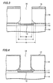
- Next, the above-described conventional semiconductor device manufacturing method will be partially described with reference to figures. Figs. 11 and 12 are cross-sectional views showing the conventional semiconductor device manufacturing method.
- In the conventional semiconductor device, as shown in Fig. 11, a
pad electrode 52 is formed on a front surface of asemiconductor substrate 50 with aninsulation film 51 therebetween in so-called front-end processes. Furthermore, in subsequent processes, a supportingbody 54 is attached on the front surface of thesemiconductor substrate 50 formed with thepad electrode 52 with aresin layer 53 therebetween. Thermal stresses (called residual stress or intrinsic stress) are likely to be generated in thepad electrode 52 when thepad electrode 52 is deposited. - However, as shown in Fig. 12, when the
semiconductor substrate 50 is etched using theresist layer 55 as a mask to form avia hole 56 penetrating thesemiconductor substrate 50, thepad electrode 52 at a bottom of thevia hole 56 is deformed, projecting into thevia hole 56, although it should be flat. - This deformation of the
pad electrode 52 is caused by that the stress accumulated in thepad electrode 52 when thepad electrode 52 is deposited in the front-end processes loses its balance by a thermal load in a thermal cycle test and so on, and thus the stress is concentrated in thepad electrode 52 at the bottom of thevia hole 56 so as to be released therefrom. Furthermore, the deformation also occurs after theinsulation film 51 is etched. - Furthermore, after a penetrating electrode (not shown) formed of, for example, copper (Cu) is formed, being connected with the
pad electrode 52 at the bottom of thevia hole 56, thepad electrode 52 is deformed projecting on the back surface side of thesemiconductor substrate 50 like being pulled by the penetrating electrode. This deformation is caused by a relation between residual stress accumulated in the penetrating electrode when the penetrating electrode is formed and the stress accumulated in thepad electrode 52. - Furthermore, the deformation of the
pad electrode 52 described above sometimes causes damage or disconnection in thepad electrode 52 by metal fatigue. Therefore, after the penetrating electrode (not shown) formed of, for example, copper (Cu) is formed in thevia hole 56 including on thedeformed pad electrode 52, there sometimes occurs connection failure between the penetrating electrode and the pad electrode exposed in thevia hole 56. That is, the deformation of thepad electrode 52 causes a problem of decreasing the reliability of the semiconductor device having the penetrating electrode. As a result, the reliability and yield of the semiconductor device having the penetrating electrode decreases. - It is an object of this invention to provide a semiconductor device and a manufacturing method that lessens this drawback.
- The solution according to the invention lies in the features of the independent claims and preferably in those of the dependent claims.
- The invention provides a semiconductor device that includes a semiconductor die having a first insulation film disposed on the front surface and a pad electrode disposed on part of the first insulation film. The semiconductor die has a via hole formed from the back surface of the semiconductor die toward the pad electrode, and the diameter of the via hole at the front surface is larger than the width of the pad electrode.
- The invention provides another semiconductor device that includes a semiconductor die having a first insulation film disposed on the front surface, and a pad electrode disposed on part of the first insulation film. The semiconductor die has a via hole formed from the back surface of the semiconductor die toward the pad electrode, and at least part of the rim portion of the via hole at the front surface extends beyond the area of the front surface covered by the pad electrode.
- The invention also provides a method of manufacturing a semiconductor device. The method includes providing a semiconductor substrate having a first insulation film disposed on the front surface thereof and a pad electrode disposed on the first insulation film, etching the semiconductor substrate from the back surface to form a via hole to expose the first insulation film located above the pad electrode, and etching the exposed first insulation film to expose at least part of the pad electrode. The etching of the semiconductor substrate is performed so that a diameter of the via hole at the front surface is larger than a width of the pad electrode.
- The invention provides another method of manufacturing a semiconductor device. The method includes providing a semiconductor substrate having an insulation film disposed on the front surface and a pad electrode disposed on the insulation film, etching the semiconductor substrate from the back surface to form a via hole to expose the insulation film located above the pad electrode, and etching the exposed insulation film to expose at least part of the pad electrode. The etching of the semiconductor substrate is performed so that at least part of a rim portion of the via hole at the front surface extends beyond an area of the front surface covered by the pad electrode.
- By virtue of this invention, any stress that is accumulated in the pad electrode (stress accumulated when the pad electrode is deposited) can be released from the bottom of the via hole more effectively than in the conventional art. This can minimize the deformation of the pad electrode exposed at the bottom of the via hole. Furthermore, the minimization of the deformation of the pad electrode exposed at the bottom of the via hole prevents connection failure occurring between the pad electrode and the penetrating electrode connected therewith, thereby enhancing reliability in the connection between the penetrating electrode and the pad electrode. As a result, the reliability and yield of the semiconductor device can be enhanced.
-
- Figs. 1 to 8 are cross-sectional views for explaining a semiconductor device manufacturing method of an embodiment of the invention.
- Fig. 9 is a cross-sectional view for explaining a semiconductor device and the manufacturing method thereof of the embodiment of the invention.
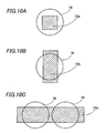
- Figs. 10A, 10B, and 10C are views showing a positional relation between a pad electrode and a via hole of the invention.
- Figs. 11 and 12 are cross-sectional views showing a conventional semiconductor device manufacturing method.
- A semiconductor device manufacturing method of an embodiment of the invention will be described with reference to figures. Figs. 1 to 9 are cross-sectional views showing the semiconductor device manufacturing method of the embodiment. Figs. 1 to 9 show a portion of a semiconductor substrate near a dicing line (not shown).
- First, as shown in Fig. 1, a
semiconductor substrate 10 formed with an electronic device (not shown) on its front surface is prepared. The electronic device (not shown) is a light receiving element such as a CCD (Charge Coupled Device) or an infrared ray sensor, or a light emissive element, for example. Alternatively, the electronic device (not shown) can be the other electronic device than the light receiving element or the light emissive element. Thesemiconductor substrate 10 is formed of a silicon substrate, for example, but can be a substrate formed of the other material. Thesemiconductor substrate 10 preferably has a thickness of about 130 µm. - Next, a
first insulation film 11 is formed as an interlayer insulation film on the front surface of thesemiconductor substrate 10 including the electronic device (not shown). Thefirst insulation film 11 is formed of, for example, a P-TEOS film or a BPSG film. Thefirst insulation film 11 preferably has a thickness of about 0.8 µm. - Furthermore, a
pad electrode 12 as an external connection electrode is formed on the front surface of thesemiconductor substrate 10, being connected with the electronic device (not shown). Thepad electrode 12 is formed on the front surface of thesemiconductor substrate 10 with thefirst insulation film 11 therebetween. Thepad electrode 12 is formed of, for example, aluminum (Al), and preferably has a thickness of about 1 µm. At this time, thepad electrode 12 is deposited flat, and a predetermined amount of stress corresponding to a deposition condition is accumulated in thepad electrode 12. - The electronic device (not shown), the
first insulation film 11, and thepad electrode 12 described above are formed in so-called front-end processes in a semiconductor device manufacturing process. - Next, according to needs, a supporting
body 14 is attached on the front surface of thesemiconductor substrate 10 with aresin layer 13 therebetween. In a case that the electronic device (not shown) is the light receiving element or the light emissive element, the supportingbody 14 is formed of a transparent or semitransparent material such as glass, for example. In a case that the electronic device (not shown) is not the light receiving element or the light emissive element, the supportingbody 14 is not necessarily formed of a transparent or semitransparent material. The supportingbody 14 can form a tape-like shape. Furthermore, this supportingbody 14 can be removed in a subsequent process. Alternatively, the supportingbody 14 can be left without removed, or the attachment of the supportingbody 14 can be omitted. - Next, as shown in Fig. 2, a first resist
layer 15 is selectively formed on a back surface of thesemiconductor substrate 10. That is, the first resistlayer 15 has an opening in a position corresponding to thepad electrode 12 on the back surface of thesemiconductor substrate 10. - Next, the
semiconductor substrate 10 is etched by, preferably, a dry etching method using this first resistlayer 15 as a mask. This etching is performed under a condition such that an opening diameter A of the viahole 16 at its bottom becomes larger than a width C of thepad electrode 12. Furthermore, this etching can be performed under a condition such that an opening diameter B of the viahole 16 at its top to middle of the depth is smaller than the opening diameter A of the viahole 16 at its bottom and the width C of thepad electrode 12. - As etching gas, gas containing SF6, O2, C4F8, or the like is used, for example. When SF6 and O2 is used as etching gas, it is preferable to perform the etching under the etching condition of about 1.5KW of power, 300/30sccm of gas flow, and 25Pa of pressure, for example.
- By this etching, the via hole penetrating the
semiconductor substrate 10 from the back surface to the front surface is formed above thepad electrode 12, having characteristics described below. That is, thefirst insulation film 11 is exposed at the bottom of the viahole 16. The etching of thesubstrate 10 is continued even after thefirst insulation film 11 is exposed at the bottom of the viahole 16, so that the sidewall of the viahole 16 is further etched and the opening of the viahole 16 at its bottom is widened as shown in FIG.2. As a result, the opening diameter A of the viahole 16 at its bottom is larger than the width C of thepad electrode 12. Referring to thepad electrode 12 adjacent to thefirst insulation film 11 at the bottom of the viahole 16, its whole surface (the surface on the side opposed to the via hole 16) is opposed to the opening of the viahole 16 with thefirst insulation film 11 therebetween. - As described above, an area of the opening of the via
hole 16 opposed to thepad electrode 12 is larger than an area of an opening of a viahole 56 opposed to apad electrode 52 of the conventional semiconductor device. Therefore, stress accumulated in thepad electrode 12 when thepad electrode 12 is deposited is released from the bottom of the viahole 16 more effectively than in the conventional art. This minimizes the deformation of thepad electrode 12 such as projecting into the viahole 16 as has been seen in the conventional art. Furthermore, since a rim of the opening is not positioned above thepad electrode 12, the deformation of thepad electrode 12 with this rim of the opening as a fulcrum can be prevented. This can minimize damage or disconnection caused by metal fatigue from occurring in thepad electrode 12. - Next, as shown in Fig. 3, a part of the
first insulation film 11 exposed at the bottom of the viahole 16 is selectively removed using the first resistlayer 15 as a mask. By this process, a part of thepad electrode 12 is exposed at the bottom of the viahole 16. Then, the first resistlayer 15 is removed. - Next, as shown in Fig. 4, a
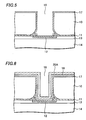
second insulation film 17 is formed on the back surface of thesemiconductor substrate 10 including in the viahole 16. Thesecond insulation film 17 is formed of, for example, a silicon oxide film (SiO2 film) or a silicon nitride film (SiN film), and formed by, for example, a plasma CVD method. Thesecond insulation film 17 preferably has a thickness of about 1 to 2 µm. - Next, as shown in Fig. 5, the
second insulation film 17 is etched from the back surface of thesemiconductor substrate 10 by, preferably, an anisotropic dry etching. Thesecond insulation film 17 formed at the bottom of the viahole 16 is thinner than that formed on the back surface of thesemiconductor substrate 10, corresponding to the depth of the viahole 16. Therefore, by the described etching, thesecond insulation film 17 is removed to expose a part of thepad electrode 12 at the bottom of the viahole 16, but thesecond insulation film 17 remains on the back surface ofsemiconductor substrate 10 and on the sidewall of the viahole 16. - Next, as shown in Fig. 6, a
barrier metal layer 18 is formed on thesecond insulation film 17 in the viahole 16 and on the back surface of thesemiconductor substrate 10. Thebarrier metal layer 18 is formed of a metal layer such as a titanium tungsten (TiW) layer, a titanium nitride (TiN) layer, or a tantalum nitride (TaN) layer, for example. - The
barrier metal layer 18 is formed by a sputtering method, a CVD method, an electroless plating method, or the other deposition methods, for example. - A seed layer (not shown) is formed on this
barrier metal layer 18. This seed layer is to be an electrode for forming awiring formation layer 20A by plating which will be described below, and formed of metal such as copper (Cu), for example. - In a case that the
second insulation film 17 on the sidewall of the viahole 16 is formed of a silicon nitride film (SiN film), thebarrier metal layer 18 can be omitted, since the silicon nitride film (SiN film) serves as a barrier against copper diffusion. - Next, the
wiring formation layer 20A is formed so as to cover thebarrier metal layer 18 and the seed layer formed on the back surface of thesemiconductor substrate 10. Thewiring formation layer 20A is a metal layer formed of copper (Cu) by an electrolytic plating method, for example. - Then, as shown in Fig. 7, a second resist
layer 19 is formed on thewiring formation layer 20A in a predetermined region. Then, thewiring formation layer 20A is patterned using the second resistlayer 19 as a mask to form a penetratingelectrode 20 and awiring layer 21 continued to and electrically connected with this penetratingelectrode 20. A plating thickness of the penetratingelectrode 20 is determined to a thickness such that the penetratingelectrode 20 does not fill the viahole 16 completely. Alternatively, the penetratingelectrode 20 can be formed to fill the viahole 16 completely. It is noted that the predetermined region to be formed with the second resistlayer 19 means a region to be formed with thewiring layer 21 having a predetermined pattern, which will be descried below, including a region formed with the viahole 16, on the back surface of thesemiconductor substrate 10. - The penetrating
electrode 20 is electrically connected with thepad electrode 12 exposed at the bottom of the viahole 16 with the seed layer and thebarrier metal layer 18 therebetween. Furthermore, thewiring layer 21 connected with the penetratingelectrode 20 is formed on the back surface of thesemiconductor substrate 10 with the seed layer and thebarrier metal layer 18 therebetween, having a predetermined pattern. Then, after the second resistlayer 19 is removed, thebarrier metal layer 18 is patterned and removed using thewiring layer 21 and the seed layer as a mask. - It is possible to form the above-described penetrating
electrode 20 andwiring layer 21 in different processes, respectively. The formation of the penetratingelectrode 20 and thewiring layer 21 can be performed not by the described electrolytic plating method using copper (Cu), but by other deposition methods using other metals. For example, the penetratingelectrode 20 and thewiring layer 21 can be formed of aluminum (Al) or aluminum alloy, by a sputtering method. In this case, after a barrier metal layer (not shown) is formed on the back surface of thesemiconductor substrate 10 excluding the viahole 16, a resist layer (not shown) is formed in a predetermined region on the barrier metal layer including the region formed with the viahole 16. Then, the penetrating electrode and the wiring layer formed of the above-mentioned metal are formed by a sputtering method using the resist layer as a mask. Alternatively, the penetratingelectrode 20 and thewiring layer 21 can be formed by a CVD method. - Then, as shown in Fig. 8, a
protection layer 22 formed of, for example, a resist material and so on is formed on the back surface of thesemiconductor substrate 10 including in the viahole 16, that is, over thesecond insulation film 17, the penetratingelectrode 20, and thewiring layer 21, covering these. An opening is provided in theprotection layer 22 in a position corresponding to thewiring layer 21. Then, a ball-shaped conductive terminal 23 formed of, for example, metal such as solder is formed on thewiring layer 21 exposed in the opening. - Next, as shown in Fig. 9, the
semiconductor substrate 10 is diced along a dicing line (not shown). Then, a plurality of semiconductor devices each formed of asemiconductor die 10A having the penetratingelectrode 20 is completed. - As described above, in the semiconductor device and the manufacturing method thereof of the embodiment, the semiconductor device having the opening diameter A of the via
hole 16 at its bottom larger than the width C of thepad electrode 12 can be manufactured. Therefore, stress accumulated in the pad electrode 12 (stress accumulated when the pad electrode is deposited) can be released from the bottom of the viahole 16 more effectively than in the conventional art. - This can minimize the deformation of the
pad electrode 12 exposed at the bottom of the viahole 16. Furthermore, the minimization of the deformation of thepad electrode 12 exposed at the bottom of the viahole 16 prevents connection failure occurring between thepad electrode 12 and the penetratingelectrode 20 connected therewith, thereby enhancing reliability in the connection between the penetratingelectrode 20 and thepad electrode 12. As a result, the reliability and yield of the semiconductor device having the penetratingelectrode 20 can be enhanced. - The above-described embodiment is not limited to the formation of the
conductive terminal 23. That is, theconductive terminal 23 is not necessarily formed as long as the penetratingelectrode 20 and thewiring layer 21 can be electrically connected with a circuit board (not shown). For example, when the semiconductor device is an LGA(Land Grid Array) type semiconductor device, it is not necessary to form theconductive terminal 23 on thewiring layer 21 in a region partially exposed from theprotection layer 22. - Furthermore, the described embodiment is not limited to the formation of the
wiring layer 21. That is, when the penetratingelectrode 20 is formed filling the viahole 16 completely, thewiring layer 21 is not necessarily formed. For example, the penetratingelectrode 20 can be directly connected with a circuit board (not shown) without thewiring layer 21 and theconductive terminal 23 therebetween. Alternatively, the penetratingelectrode 20 can have theconductive terminal 23 on the penetratingelectrode 20 exposed at the opening of the viahole 16, and connected with a circuit board (not shown) with theconductive terminal 23 therebetween and without thewiring layer 21 therebetween. - Figs. 10A, 10B, and 10C are plan views showing a positional relation between the
pad electrode 12 and the viahole 16 of the invention. Fig. 10A shows an example that the opening diameter of the viahole 16 is larger than the width of thepad electrode 12a, and Figs. 10B and 10C show examples that some portions of the opening rim of the viahole 16 are not positioned above thepad electrode 12, and the viahole 16 has both regions where its opening diameter is larger and smaller than the width of thepad electrode 12b. Fig. 10C shows an example that a plurality of viaholes 16 is formed for onepad electrode 12c. Since thepad electrode 12 starts projecting with the opening rim positioned above thepad electrode 12 as a fulcrum in the conventional semiconductor device, thepad electrode 12 largely stretches from this opening rim. In this embodiment, however, there does not exist the opening rim positioned abovepad electrode 12, which serves as the fulcrum of the projection, so that the projection can be prevented. - Furthermore, even in the case that only some portions of the opening rim of the via
hole 16 are not positioned above thepad electrodes whole pad electrode 12a is not open to the opening of the viahole 16, unlike in Fig. 10A, it is possible to prevent the projection of thepad electrode 12. In the invention, the projection can be reduced even in the case that only some portions of the opening rim are not positioned above thepad electrode 12, thereby enhancing the reliability of the semiconductor device.
Claims (10)
- A semiconductor device comprising:- a semiconductor die comprising a first insulation film (11) disposed on a front surface thereof; and- a pad electrode (12) disposed on part of the first insulation film (11),wherein the semiconductor die has a via hole (16) formed from a back surface of the semiconductor die toward the pad electrode (12), and a diameter (A) of the via hole (16) at the front surface is larger than a width (C) of the pad electrode (12).
- The semiconductor device of claim 1, wherein a diameter (B) of the via hole (16) at a middle portion thereof is smaller than the width (C) of the pad electrode (12) and smaller than the diameter (A) of the via hole (16) at the front surface.
- The semiconductor device of claim 1 or 2, further comprising a second insulation film (17) disposed on the back surface of the semiconductor die and on a sidewall of the via hole (16), a penetrating electrode (20) disposed on the second insulation film (17) in the via hole (16) and electrically connected with the pad electrode (12), a wiring layer (21) electrically connected with the penetrating electrode (20) and extending onto the second insulation film (17) on the back surface of the semiconductor die, and a protection layer (22) disposed on the back surface of the semiconductor die so as to cover at least part of the wiring layer (21).
- The semiconductor device of claim 3, further comprising a conductive terminal (23) disposed on the wiring layer (21) not covered by the protection layer (22).
- A semiconductor device comprising:- a semiconductor die comprising a first insulation film (11) disposed on a front surface thereof; and- a pad electrode (12) disposed on part of the first insulation film (11),wherein the semiconductor die has a via hole (16) formed from a back surface of the semiconductor die toward the pad electrode (12), and at least part of a rim portion of the via hole (16) at the front surface extends beyond an area of the front surface covered by the pad electrode (12).
- A method of manufacturing a semiconductor device, comprising:- providing a semiconductor substrate (10) comprising a first insulation film (11) disposed on a front surface thereof and a pad electrode (12) disposed on the first insulation film (11);- etching the semiconductor substrate (10) from a back surface thereof to form a via hole (16) to expose the first insulation film (11) located above the pad electrode (12); and- etching the exposed first insulation film (11) to expose at least part of the pad electrode (12),wherein the etching of the semiconductor substrate (10) is performed so that a diameter (A) of the via hole (16) at the front surface is larger than a width (C) of the pad electrode (12).
- The method of claim 6, further comprising forming a second insulation film (17) on the back surface of the semiconductor substrate (10) and in the via hole (16), exposing part of the pad electrode (12) by etching the second insulation film (17), forming a penetrating electrode (20) electrically connected with the pad electrode (12) in the via hole (16) and a wiring layer (21) electrically connected with the penetrating electrode (20) and extending onto the second insulation film (17) on the back surface of the semiconductor substrate (10), forming a protection layer (22) on the back surface of the semiconductor substrate (10) so as to cover at least part of the wiring layer (21), and cutting the semiconductor substrate (10) to produce a semiconductor die.
- The method of claim 7, further comprising forming a conductive terminal (23) on the wiring layer (21) not covered by the protection layer (22).
- The method according to any of claims 6 to 8, wherein the etching of the semiconductor substrate (10) is performed so that the diameter (A) of the via hole (16) at the front surface is made larger than a diameter (B) of the via hole (16) at a middle portion thereof by over-etching the semiconductor substrate (10).
- A method of manufacturing a semiconductor device, comprising:- providing a semiconductor substrate (10) comprising an insulation film (11) disposed on a front surface thereof and a pad electrode (12) disposed on the insulation film (11);- etching the semiconductor substrate (10) from a back surface thereof to form a via hole (16) to expose the insulation film (11) located above the pad electrode (12); and- etching the exposed insulation film (11) to expose at least part of the pad electrode (12),wherein the etching of the semiconductor substrate (10) is performed so that at least part of a rim portion of the via hole (16) at the front surface extends beyond an area of the front surface covered by the pad electrode (12).
Applications Claiming Priority (1)
| Application Number | Priority Date | Filing Date | Title |
|---|---|---|---|
| JP2004310726A JP4443379B2 (en) | 2004-10-26 | 2004-10-26 | Manufacturing method of semiconductor device |
Publications (2)
| Publication Number | Publication Date |
|---|---|
| EP1653509A2 true EP1653509A2 (en) | 2006-05-03 |
| EP1653509A3 EP1653509A3 (en) | 2009-06-03 |
Family
ID=35385569
Family Applications (1)
| Application Number | Title | Priority Date | Filing Date |
|---|---|---|---|
| EP05023409A Withdrawn EP1653509A3 (en) | 2004-10-26 | 2005-10-26 | Semiconductor device and manufacturing method of the same |
Country Status (6)
| Country | Link |
|---|---|
| US (2) | US7339273B2 (en) |
| EP (1) | EP1653509A3 (en) |
| JP (1) | JP4443379B2 (en) |
| KR (1) | KR100647760B1 (en) |
| CN (1) | CN100429770C (en) |
| TW (1) | TWI267132B (en) |
Cited By (3)
| Publication number | Priority date | Publication date | Assignee | Title |
|---|---|---|---|---|
| DE102009049102A1 (en) * | 2009-10-13 | 2011-04-21 | Austriamicrosystems Ag | Semiconductor device with via and method for producing a via in a semiconductor device |
| EP2357665A3 (en) * | 2010-01-20 | 2014-01-01 | Xintec Inc. | Chip package and method for fabricating the same |
| EP4109507A1 (en) * | 2021-06-24 | 2022-12-28 | Intel Corporation | Metal line profile shaping for advanced integrated circuit structure fabrication |
Families Citing this family (42)
| Publication number | Priority date | Publication date | Assignee | Title |
|---|---|---|---|---|
| JP4850392B2 (en) * | 2004-02-17 | 2012-01-11 | 三洋電機株式会社 | Manufacturing method of semiconductor device |
| JP4443379B2 (en) * | 2004-10-26 | 2010-03-31 | 三洋電機株式会社 | Manufacturing method of semiconductor device |
| TWI303864B (en) * | 2004-10-26 | 2008-12-01 | Sanyo Electric Co | Semiconductor device and method for making the same |
| JP4873517B2 (en) * | 2004-10-28 | 2012-02-08 | オンセミコンダクター・トレーディング・リミテッド | Semiconductor device and manufacturing method thereof |
| US7485967B2 (en) * | 2005-03-10 | 2009-02-03 | Sanyo Electric Co., Ltd. | Semiconductor device with via hole for electric connection |
| TWI269419B (en) * | 2005-06-09 | 2006-12-21 | Advanced Semiconductor Eng | Method for forming wafer-level heat spreader structure and packaging structure thereof |
| JP2007150083A (en) * | 2005-11-29 | 2007-06-14 | Elpida Memory Inc | Method of manufacturing semiconductor device |
| KR100884238B1 (en) * | 2006-05-22 | 2009-02-17 | 삼성전자주식회사 | Semiconductor Package Having Anchor Type Joining And Method Of Fabricating The Same |
| JP4773307B2 (en) * | 2006-09-15 | 2011-09-14 | Okiセミコンダクタ株式会社 | Manufacturing method of semiconductor device |
| JP4979320B2 (en) * | 2006-09-28 | 2012-07-18 | ルネサスエレクトロニクス株式会社 | Semiconductor wafer, manufacturing method thereof, and manufacturing method of semiconductor device |
| US8212331B1 (en) * | 2006-10-02 | 2012-07-03 | Newport Fab, Llc | Method for fabricating a backside through-wafer via in a processed wafer and related structure |
| JP5242070B2 (en) * | 2007-03-29 | 2013-07-24 | 株式会社フジクラ | Through wiring board |
| JP4585561B2 (en) * | 2007-09-04 | 2010-11-24 | 株式会社東芝 | Manufacturing method of semiconductor device |
| TWI331488B (en) * | 2007-10-09 | 2010-10-01 | Unimicron Technology Corp | Printed circuit board and fabrication method thereof |
| US7566637B2 (en) * | 2007-12-13 | 2009-07-28 | International Business Machines Corporation | Method of inhibition of metal diffusion arising from laser dicing |
| JP5259197B2 (en) * | 2008-01-09 | 2013-08-07 | ソニー株式会社 | Semiconductor device and manufacturing method thereof |
| DE102008033395B3 (en) | 2008-07-16 | 2010-02-04 | Austriamicrosystems Ag | Method for producing a semiconductor component and semiconductor component |
| JP5242282B2 (en) * | 2008-07-31 | 2013-07-24 | 株式会社東芝 | Semiconductor device and manufacturing method thereof |
| US7906404B2 (en) * | 2008-11-21 | 2011-03-15 | Teledyne Scientific & Imaging, Llc | Power distribution for CMOS circuits using in-substrate decoupling capacitors and back side metal layers |
| US8343806B2 (en) | 2009-03-05 | 2013-01-01 | Raytheon Company | Hermetic packaging of integrated circuit components |
| US20100258952A1 (en) * | 2009-04-08 | 2010-10-14 | Interconnect Portfolio Llc | Interconnection of IC Chips by Flex Circuit Superstructure |
| JP5532394B2 (en) | 2009-10-15 | 2014-06-25 | セイコーエプソン株式会社 | Semiconductor device, circuit board, and electronic equipment |
| CN102148202B (en) * | 2010-02-09 | 2016-06-08 | 精材科技股份有限公司 | Wafer encapsulation body and forming method thereof |
| JP5730654B2 (en) * | 2010-06-24 | 2015-06-10 | 新光電気工業株式会社 | Wiring board and manufacturing method thereof |
| US9190325B2 (en) * | 2010-09-30 | 2015-11-17 | Taiwan Semiconductor Manufacturing Company, Ltd. | TSV formation |
| US8901701B2 (en) * | 2011-02-10 | 2014-12-02 | Chia-Sheng Lin | Chip package and fabrication method thereof |
| TWI485818B (en) * | 2011-06-16 | 2015-05-21 | Xintec Inc | Chip package and method for forming the same |
| CN102891120B (en) * | 2011-07-22 | 2016-06-08 | 精材科技股份有限公司 | Wafer encapsulation body and forming method thereof |
| US8816505B2 (en) * | 2011-07-29 | 2014-08-26 | Tessera, Inc. | Low stress vias |
| JP5832852B2 (en) | 2011-10-21 | 2015-12-16 | 浜松ホトニクス株式会社 | Photodetector |
| JP5791461B2 (en) | 2011-10-21 | 2015-10-07 | 浜松ホトニクス株式会社 | Photodetector |
| RU2546856C2 (en) * | 2013-05-28 | 2015-04-10 | Закрытое акционерное общество "НИИМП-Т" | Production of semiconductor microwave devices |
| US10727122B2 (en) | 2014-12-08 | 2020-07-28 | International Business Machines Corporation | Self-aligned via interconnect structures |
| JP6269703B2 (en) | 2016-02-24 | 2018-01-31 | トヨタ自動車株式会社 | Hydraulic control device for power transmission device for vehicle |
| JP6282307B2 (en) * | 2016-06-01 | 2018-02-21 | 浜松ホトニクス株式会社 | Semiconductor photo detector |
| US9893083B1 (en) | 2016-10-13 | 2018-02-13 | Micron Technology, Inc. | Elevationally-extending strings of memory cells individually comprising a programmable charge storage transistor and methods of processing silicon nitride-comprising materials |
| US20180122749A1 (en) * | 2016-11-01 | 2018-05-03 | Advanced Semiconductor Engineering, Inc. | Semiconductor wafer, semiconductor package and method for manufacturing the same |
| EP3460835B1 (en) * | 2017-09-20 | 2020-04-01 | ams AG | Method for manufacturing a semiconductor device and semiconductor device |
| US11749790B2 (en) | 2017-12-20 | 2023-09-05 | Lumileds Llc | Segmented LED with embedded transistors |
| CN110739269B (en) * | 2019-10-25 | 2020-11-20 | 武汉新芯集成电路制造有限公司 | Semiconductor device and method of forming the same |
| US11482506B2 (en) * | 2020-03-31 | 2022-10-25 | Taiwan Semiconductor Manufacturing Company Limited | Edge-trimming methods for wafer bonding and dicing |
| CN113539945B (en) * | 2020-04-16 | 2023-09-29 | 长鑫存储技术有限公司 | Semiconductor structure and forming method thereof |
Citations (4)
| Publication number | Priority date | Publication date | Assignee | Title |
|---|---|---|---|---|
| US4097890A (en) | 1976-06-23 | 1978-06-27 | Hewlett-Packard Company | Low parasitic capacitance and resistance beamlead semiconductor component and method of manufacture |
| US5056216A (en) | 1990-01-26 | 1991-10-15 | Sri International | Method of forming a plurality of solder connections |
| US20020170173A1 (en) | 2001-05-21 | 2002-11-21 | Shinko Electric Industries Co., Ltd. | Method of production of circuit board, semiconductor device, and plating system |
| EP1564805A1 (en) | 2004-02-17 | 2005-08-17 | Sanyo Electric Co., Ltd. | Semiconductor device and manufacturing method thereof |
Family Cites Families (67)
| Publication number | Priority date | Publication date | Assignee | Title |
|---|---|---|---|---|
| FR2637151A1 (en) | 1988-09-29 | 1990-03-30 | Commissariat Energie Atomique | METHOD OF MAKING ELECTRICAL CONNECTIONS THROUGH A SUBSTRATE |
| US5229647A (en) * | 1991-03-27 | 1993-07-20 | Micron Technology, Inc. | High density data storage using stacked wafers |
| US5149674A (en) | 1991-06-17 | 1992-09-22 | Motorola, Inc. | Method for making a planar multi-layer metal bonding pad |
| US5336626A (en) * | 1992-03-18 | 1994-08-09 | Samsung Electronics Co., Ltd. | Method of manufacturing a MESFET with an epitaxial void |
| US5248903A (en) | 1992-09-18 | 1993-09-28 | Lsi Logic Corporation | Composite bond pads for semiconductor devices |
| US5432119A (en) * | 1994-01-31 | 1995-07-11 | Hughes Aircraft Company | High yield electron-beam gate fabrication method for sub-micron gate FETS |
| WO1996013062A1 (en) | 1994-10-19 | 1996-05-02 | Ceram Incorporated | Apparatus and method of manufacturing stacked wafer array |
| US6204074B1 (en) | 1995-01-09 | 2001-03-20 | International Business Machines Corporation | Chip design process for wire bond and flip-chip package |
| JPH08293523A (en) | 1995-02-21 | 1996-11-05 | Seiko Epson Corp | Semiconductor device and its manufacture |
| JPH09321175A (en) | 1996-05-30 | 1997-12-12 | Oki Electric Ind Co Ltd | Microwave circuit and chip |
| EP0851724B1 (en) | 1996-12-26 | 2003-10-22 | Matsushita Electric Industrial Co., Ltd. | Printed circuit board and electric components |
| US5910687A (en) | 1997-01-24 | 1999-06-08 | Chipscale, Inc. | Wafer fabrication of die-bottom contacts for electronic devices |
| EP0860876A3 (en) | 1997-02-21 | 1999-09-22 | DaimlerChrysler AG | Arrangement and method for manufacturing CSP-packages for electrical components |
| US5915167A (en) | 1997-04-04 | 1999-06-22 | Elm Technology Corporation | Three dimensional structure memory |
| JP3724110B2 (en) | 1997-04-24 | 2005-12-07 | 三菱電機株式会社 | Manufacturing method of semiconductor device |
| US5985749A (en) | 1997-06-25 | 1999-11-16 | Vlsi Technology, Inc. | Method of forming a via hole structure including CVD tungsten silicide barrier layer |
| IL123207A0 (en) | 1998-02-06 | 1998-09-24 | Shellcase Ltd | Integrated circuit device |
| JP2974022B1 (en) | 1998-10-01 | 1999-11-08 | ヤマハ株式会社 | Bonding pad structure of semiconductor device |
| JP3382549B2 (en) * | 1998-11-02 | 2003-03-04 | キヤノン株式会社 | Semiconductor device and active matrix substrate |
| TW442873B (en) | 1999-01-14 | 2001-06-23 | United Microelectronics Corp | Three-dimension stack-type chip structure and its manufacturing method |
| US6110816A (en) | 1999-03-05 | 2000-08-29 | Taiwan Semiconductor Manufacturing Company | Method for improving bondability for deep-submicron integrated circuit package |
| US6031293A (en) * | 1999-04-26 | 2000-02-29 | United Microelectronics Corporation | Package-free bonding pad structure |
| US6300670B1 (en) | 1999-07-26 | 2001-10-09 | Stmicroelectronics, Inc. | Backside bus vias |
| JP3468188B2 (en) * | 2000-01-24 | 2003-11-17 | ヤマハ株式会社 | Semiconductor device and its manufacturing method. |
| JP3629178B2 (en) * | 2000-02-21 | 2005-03-16 | Necエレクトロニクス株式会社 | Flip chip type semiconductor device and manufacturing method thereof |
| JP3778256B2 (en) * | 2000-02-28 | 2006-05-24 | セイコーエプソン株式会社 | Semiconductor device and manufacturing method thereof, circuit board, and electronic apparatus |
| JP3879816B2 (en) | 2000-06-02 | 2007-02-14 | セイコーエプソン株式会社 | SEMICONDUCTOR DEVICE AND ITS MANUFACTURING METHOD, LAMINATED SEMICONDUCTOR DEVICE, CIRCUIT BOARD AND ELECTRONIC DEVICE |
| JP4329235B2 (en) | 2000-06-27 | 2009-09-09 | セイコーエプソン株式会社 | Semiconductor device and manufacturing method thereof |
| US6562709B1 (en) * | 2000-08-22 | 2003-05-13 | Charles W. C. Lin | Semiconductor chip assembly with simultaneously electroplated contact terminal and connection joint |
| US6512292B1 (en) | 2000-09-12 | 2003-01-28 | International Business Machines Corporation | Semiconductor chip structures with embedded thermal conductors and a thermal sink disposed over opposing substrate surfaces |
| KR100366635B1 (en) | 2000-11-01 | 2003-01-09 | 삼성전자 주식회사 | Metal layer of semiconductor device and manufacturing method thereof |
| JP4771607B2 (en) * | 2001-03-30 | 2011-09-14 | 富士通セミコンダクター株式会社 | Semiconductor device and manufacturing method thereof |
| JP2003045877A (en) * | 2001-08-01 | 2003-02-14 | Sharp Corp | Semiconductor device and its manufacturing method |
| US6734568B2 (en) | 2001-08-29 | 2004-05-11 | Kabushiki Kaisha Toshiba | Semiconductor device and method of manufacturing the same |
| JP4703061B2 (en) * | 2001-08-30 | 2011-06-15 | 富士通株式会社 | Thin film circuit board manufacturing method and via forming board forming method |
| JP2003168818A (en) * | 2001-09-18 | 2003-06-13 | Anritsu Corp | Order mesa type avalanche photodiode and its fabricating method |
| JP3998984B2 (en) * | 2002-01-18 | 2007-10-31 | 富士通株式会社 | Circuit board and manufacturing method thereof |
| US6960837B2 (en) | 2002-02-26 | 2005-11-01 | International Business Machines Corporation | Method of connecting core I/O pins to backside chip I/O pads |
| EP2560199B1 (en) | 2002-04-05 | 2016-08-03 | STMicroelectronics S.r.l. | Process for manufacturing a through insulated interconnection in a body of semiconductor material |
| JP4212293B2 (en) | 2002-04-15 | 2009-01-21 | 三洋電機株式会社 | Manufacturing method of semiconductor device |
| TWI232560B (en) | 2002-04-23 | 2005-05-11 | Sanyo Electric Co | Semiconductor device and its manufacture |
| JP2003318178A (en) * | 2002-04-24 | 2003-11-07 | Seiko Epson Corp | Semiconductor device, its manufacturing method, circuit board, and electronic apparatus |
| TWI229435B (en) | 2002-06-18 | 2005-03-11 | Sanyo Electric Co | Manufacture of semiconductor device |
| US6716737B2 (en) | 2002-07-29 | 2004-04-06 | Hewlett-Packard Development Company, L.P. | Method of forming a through-substrate interconnect |
| US6902872B2 (en) | 2002-07-29 | 2005-06-07 | Hewlett-Packard Development Company, L.P. | Method of forming a through-substrate interconnect |
| JP2004103761A (en) * | 2002-09-09 | 2004-04-02 | Renesas Technology Corp | Semiconductor device manufacturing line |
| TWI227050B (en) | 2002-10-11 | 2005-01-21 | Sanyo Electric Co | Semiconductor device and method for manufacturing the same |
| TWI227550B (en) | 2002-10-30 | 2005-02-01 | Sanyo Electric Co | Semiconductor device manufacturing method |
| JP2004186422A (en) | 2002-12-03 | 2004-07-02 | Shinko Electric Ind Co Ltd | Electronic part mounting structure and manufacturing method thereof |
| JP4145301B2 (en) | 2003-01-15 | 2008-09-03 | 富士通株式会社 | Semiconductor device and three-dimensional mounting semiconductor device |
| JP4322508B2 (en) | 2003-01-15 | 2009-09-02 | 新光電気工業株式会社 | Manufacturing method of semiconductor device |
| TWI239629B (en) | 2003-03-17 | 2005-09-11 | Seiko Epson Corp | Method of manufacturing semiconductor device, semiconductor device, circuit substrate and electronic apparatus |
| JP3972846B2 (en) | 2003-03-25 | 2007-09-05 | セイコーエプソン株式会社 | Manufacturing method of semiconductor device |
| JP2004311948A (en) * | 2003-03-27 | 2004-11-04 | Seiko Epson Corp | Semiconductor device, electronic apparatus, and method for manufacturing semiconductor device |
| US7247939B2 (en) | 2003-04-01 | 2007-07-24 | Taiwan Semiconductor Manufacturing Co., Ltd. | Metal filled semiconductor features with improved structural stability |
| JP4130158B2 (en) | 2003-06-09 | 2008-08-06 | 三洋電機株式会社 | Semiconductor device manufacturing method, semiconductor device |
| US7453158B2 (en) | 2003-07-31 | 2008-11-18 | Nvidia Corporation | Pad over active circuit system and method with meshed support structure |
| JP4323303B2 (en) | 2003-12-17 | 2009-09-02 | 株式会社フジクラ | Substrate manufacturing method |
| JP4850392B2 (en) | 2004-02-17 | 2012-01-11 | 三洋電機株式会社 | Manufacturing method of semiconductor device |
| JP2005235860A (en) | 2004-02-17 | 2005-09-02 | Sanyo Electric Co Ltd | Semiconductor device and manufacturing method thereof |
| JP4803964B2 (en) | 2004-03-17 | 2011-10-26 | 三洋電機株式会社 | Electrode structure |
| JP4376715B2 (en) * | 2004-07-16 | 2009-12-02 | 三洋電機株式会社 | Manufacturing method of semiconductor device |
| JP4373866B2 (en) * | 2004-07-16 | 2009-11-25 | 三洋電機株式会社 | Manufacturing method of semiconductor device |
| TWI303864B (en) | 2004-10-26 | 2008-12-01 | Sanyo Electric Co | Semiconductor device and method for making the same |
| JP4443379B2 (en) * | 2004-10-26 | 2010-03-31 | 三洋電機株式会社 | Manufacturing method of semiconductor device |
| JP4873517B2 (en) | 2004-10-28 | 2012-02-08 | オンセミコンダクター・トレーディング・リミテッド | Semiconductor device and manufacturing method thereof |
| US7485967B2 (en) * | 2005-03-10 | 2009-02-03 | Sanyo Electric Co., Ltd. | Semiconductor device with via hole for electric connection |
-
2004
- 2004-10-26 JP JP2004310726A patent/JP4443379B2/en not_active Expired - Fee Related
-
2005
- 2005-10-14 TW TW094135828A patent/TWI267132B/en not_active IP Right Cessation
- 2005-10-25 CN CNB2005101180996A patent/CN100429770C/en not_active Expired - Fee Related
- 2005-10-25 US US11/257,390 patent/US7339273B2/en active Active
- 2005-10-25 KR KR1020050100580A patent/KR100647760B1/en active IP Right Grant
- 2005-10-26 EP EP05023409A patent/EP1653509A3/en not_active Withdrawn
-
2008
- 2008-01-03 US US11/969,065 patent/US7670955B2/en active Active
Patent Citations (4)
| Publication number | Priority date | Publication date | Assignee | Title |
|---|---|---|---|---|
| US4097890A (en) | 1976-06-23 | 1978-06-27 | Hewlett-Packard Company | Low parasitic capacitance and resistance beamlead semiconductor component and method of manufacture |
| US5056216A (en) | 1990-01-26 | 1991-10-15 | Sri International | Method of forming a plurality of solder connections |
| US20020170173A1 (en) | 2001-05-21 | 2002-11-21 | Shinko Electric Industries Co., Ltd. | Method of production of circuit board, semiconductor device, and plating system |
| EP1564805A1 (en) | 2004-02-17 | 2005-08-17 | Sanyo Electric Co., Ltd. | Semiconductor device and manufacturing method thereof |
Cited By (5)
| Publication number | Priority date | Publication date | Assignee | Title |
|---|---|---|---|---|
| DE102009049102A1 (en) * | 2009-10-13 | 2011-04-21 | Austriamicrosystems Ag | Semiconductor device with via and method for producing a via in a semiconductor device |
| DE102009049102B4 (en) * | 2009-10-13 | 2012-10-04 | Austriamicrosystems Ag | Semiconductor device with via and method for producing a via in a semiconductor device |
| US8531041B2 (en) | 2009-10-13 | 2013-09-10 | Ams Ag | Semiconductor component having a plated through-hole and method for the production thereof |
| EP2357665A3 (en) * | 2010-01-20 | 2014-01-01 | Xintec Inc. | Chip package and method for fabricating the same |
| EP4109507A1 (en) * | 2021-06-24 | 2022-12-28 | Intel Corporation | Metal line profile shaping for advanced integrated circuit structure fabrication |
Also Published As
| Publication number | Publication date |
|---|---|
| TW200616055A (en) | 2006-05-16 |
| EP1653509A3 (en) | 2009-06-03 |
| US20060108695A1 (en) | 2006-05-25 |
| CN1779961A (en) | 2006-05-31 |
| JP4443379B2 (en) | 2010-03-31 |
| US7339273B2 (en) | 2008-03-04 |
| US20080132038A1 (en) | 2008-06-05 |
| CN100429770C (en) | 2008-10-29 |
| JP2006128172A (en) | 2006-05-18 |
| US7670955B2 (en) | 2010-03-02 |
| TWI267132B (en) | 2006-11-21 |
| KR100647760B1 (en) | 2006-11-23 |
| KR20060049324A (en) | 2006-05-18 |
Similar Documents
| Publication | Publication Date | Title |
|---|---|---|
| US7339273B2 (en) | Semiconductor device with a via hole having a diameter at the surface larger than a width of a pad electrode | |
| US7582971B2 (en) | Semiconductor device and manufacturing method of the same | |
| US7485967B2 (en) | Semiconductor device with via hole for electric connection | |
| EP1564810B1 (en) | Semiconductor device and manufacturing method thereof | |
| EP1564807B1 (en) | Semiconductor device and manufacturing method of the same | |
| US7382037B2 (en) | Semiconductor device with a peeling prevention layer | |
| KR100682434B1 (en) | Semiconductor device and manufacturing method thereof | |
| KR100608184B1 (en) | Semiconductor device and method for manufacturing the same | |
| US8035215B2 (en) | Semiconductor device and manufacturing method of the same | |
| EP1482553A2 (en) | Semiconductor device and manufacturing method thereof | |
| US7557017B2 (en) | Method of manufacturing semiconductor device with two-step etching of layer | |
| JP4544902B2 (en) | Semiconductor device and manufacturing method thereof | |
| JP4282514B2 (en) | Manufacturing method of semiconductor device | |
| JP4845986B2 (en) | Semiconductor device | |
| JP5258735B2 (en) | Semiconductor device |
Legal Events
| Date | Code | Title | Description |
|---|---|---|---|
| PUAI | Public reference made under article 153(3) epc to a published international application that has entered the european phase |
Free format text: ORIGINAL CODE: 0009012 |
|
| AK | Designated contracting states |
Kind code of ref document: A2 Designated state(s): AT BE BG CH CY CZ DE DK EE ES FI FR GB GR HU IE IS IT LI LT LU LV MC NL PL PT RO SE SI SK TR |
|
| AX | Request for extension of the european patent |
Extension state: AL BA HR MK YU |
|
| PUAL | Search report despatched |
Free format text: ORIGINAL CODE: 0009013 |
|
| AK | Designated contracting states |
Kind code of ref document: A3 Designated state(s): AT BE BG CH CY CZ DE DK EE ES FI FR GB GR HU IE IS IT LI LT LU LV MC NL PL PT RO SE SI SK TR |
|
| AX | Request for extension of the european patent |
Extension state: AL BA HR MK YU |
|
| 17P | Request for examination filed |
Effective date: 20091202 |
|
| AKX | Designation fees paid |
Designated state(s): DE FI FR GB |
|
| 17Q | First examination report despatched |
Effective date: 20100114 |
|
| GRAP | Despatch of communication of intention to grant a patent |
Free format text: ORIGINAL CODE: EPIDOSNIGR1 |
|
| INTG | Intention to grant announced |
Effective date: 20140710 |
|
| RIN1 | Information on inventor provided before grant (corrected) |
Inventor name: KAMEYAMA, KOJIRO Inventor name: SUZUKI, AKIRA Inventor name: UMEMOTO, MITSUO |
|
| STAA | Information on the status of an ep patent application or granted ep patent |
Free format text: STATUS: THE APPLICATION IS DEEMED TO BE WITHDRAWN |
|
| 18D | Application deemed to be withdrawn |
Effective date: 20141121 |