EP1660787B1 - Electro-mechanical continuously variable transmission - Google Patents
Electro-mechanical continuously variable transmission Download PDFInfo
- Publication number
- EP1660787B1 EP1660787B1 EP04761682.6A EP04761682A EP1660787B1 EP 1660787 B1 EP1660787 B1 EP 1660787B1 EP 04761682 A EP04761682 A EP 04761682A EP 1660787 B1 EP1660787 B1 EP 1660787B1
- Authority
- EP
- European Patent Office
- Prior art keywords
- generator
- power
- transmission
- input
- output shaft
- Prior art date
- Legal status (The legal status is an assumption and is not a legal conclusion. Google has not performed a legal analysis and makes no representation as to the accuracy of the status listed.)
- Not-in-force
Links
- 230000005540 biological transmission Effects 0.000 title claims abstract description 56
- 238000004146 energy storage Methods 0.000 claims abstract description 11
- 230000002441 reversible effect Effects 0.000 claims description 41
- 230000001172 regenerating effect Effects 0.000 claims description 12
- 239000003990 capacitor Substances 0.000 description 24
- 238000010586 diagram Methods 0.000 description 8
- 150000001875 compounds Chemical class 0.000 description 5
- 239000000446 fuel Substances 0.000 description 5
- 230000008901 benefit Effects 0.000 description 4
- 230000008929 regeneration Effects 0.000 description 4
- 238000011069 regeneration method Methods 0.000 description 4
- 230000008859 change Effects 0.000 description 3
- 238000002485 combustion reaction Methods 0.000 description 3
- 230000001351 cycling effect Effects 0.000 description 3
- 230000000694 effects Effects 0.000 description 3
- 238000000034 method Methods 0.000 description 3
- 238000006243 chemical reaction Methods 0.000 description 2
- 238000005516 engineering process Methods 0.000 description 2
- 238000012986 modification Methods 0.000 description 2
- 230000004048 modification Effects 0.000 description 2
- 239000007858 starting material Substances 0.000 description 2
- 239000013589 supplement Substances 0.000 description 2
- 230000001133 acceleration Effects 0.000 description 1
- 230000008878 coupling Effects 0.000 description 1
- 238000010168 coupling process Methods 0.000 description 1
- 238000005859 coupling reaction Methods 0.000 description 1
- 230000009977 dual effect Effects 0.000 description 1
- 238000010297 mechanical methods and process Methods 0.000 description 1
- 230000008520 organization Effects 0.000 description 1
- JTJMJGYZQZDUJJ-UHFFFAOYSA-N phencyclidine Chemical compound C1CCCCN1C1(C=2C=CC=CC=2)CCCCC1 JTJMJGYZQZDUJJ-UHFFFAOYSA-N 0.000 description 1
- 230000002035 prolonged effect Effects 0.000 description 1
- 238000011084 recovery Methods 0.000 description 1
- 230000000979 retarding effect Effects 0.000 description 1
- 239000000126 substance Substances 0.000 description 1
Images


Classifications
-
- B—PERFORMING OPERATIONS; TRANSPORTING
- B60—VEHICLES IN GENERAL
- B60K—ARRANGEMENT OR MOUNTING OF PROPULSION UNITS OR OF TRANSMISSIONS IN VEHICLES; ARRANGEMENT OR MOUNTING OF PLURAL DIVERSE PRIME-MOVERS IN VEHICLES; AUXILIARY DRIVES FOR VEHICLES; INSTRUMENTATION OR DASHBOARDS FOR VEHICLES; ARRANGEMENTS IN CONNECTION WITH COOLING, AIR INTAKE, GAS EXHAUST OR FUEL SUPPLY OF PROPULSION UNITS IN VEHICLES
- B60K6/00—Arrangement or mounting of plural diverse prime-movers for mutual or common propulsion, e.g. hybrid propulsion systems comprising electric motors and internal combustion engines ; Control systems therefor, i.e. systems controlling two or more prime movers, or controlling one of these prime movers and any of the transmission, drive or drive units Informative references: mechanical gearings with secondary electric drive F16H3/72; arrangements for handling mechanical energy structurally associated with the dynamo-electric machine H02K7/00; machines comprising structurally interrelated motor and generator parts H02K51/00; dynamo-electric machines not otherwise provided for in H02K see H02K99/00
- B60K6/20—Arrangement or mounting of plural diverse prime-movers for mutual or common propulsion, e.g. hybrid propulsion systems comprising electric motors and internal combustion engines ; Control systems therefor, i.e. systems controlling two or more prime movers, or controlling one of these prime movers and any of the transmission, drive or drive units Informative references: mechanical gearings with secondary electric drive F16H3/72; arrangements for handling mechanical energy structurally associated with the dynamo-electric machine H02K7/00; machines comprising structurally interrelated motor and generator parts H02K51/00; dynamo-electric machines not otherwise provided for in H02K see H02K99/00 the prime-movers consisting of electric motors and internal combustion engines, e.g. HEVs
- B60K6/42—Arrangement or mounting of plural diverse prime-movers for mutual or common propulsion, e.g. hybrid propulsion systems comprising electric motors and internal combustion engines ; Control systems therefor, i.e. systems controlling two or more prime movers, or controlling one of these prime movers and any of the transmission, drive or drive units Informative references: mechanical gearings with secondary electric drive F16H3/72; arrangements for handling mechanical energy structurally associated with the dynamo-electric machine H02K7/00; machines comprising structurally interrelated motor and generator parts H02K51/00; dynamo-electric machines not otherwise provided for in H02K see H02K99/00 the prime-movers consisting of electric motors and internal combustion engines, e.g. HEVs characterised by the architecture of the hybrid electric vehicle
- B60K6/44—Series-parallel type
- B60K6/445—Differential gearing distribution type
-
- F—MECHANICAL ENGINEERING; LIGHTING; HEATING; WEAPONS; BLASTING
- F16—ENGINEERING ELEMENTS AND UNITS; GENERAL MEASURES FOR PRODUCING AND MAINTAINING EFFECTIVE FUNCTIONING OF MACHINES OR INSTALLATIONS; THERMAL INSULATION IN GENERAL
- F16H—GEARING
- F16H3/00—Toothed gearings for conveying rotary motion with variable gear ratio or for reversing rotary motion
- F16H3/44—Toothed gearings for conveying rotary motion with variable gear ratio or for reversing rotary motion using gears having orbital motion
- F16H3/72—Toothed gearings for conveying rotary motion with variable gear ratio or for reversing rotary motion using gears having orbital motion with a secondary drive, e.g. regulating motor, in order to vary speed continuously
-
- B—PERFORMING OPERATIONS; TRANSPORTING
- B60—VEHICLES IN GENERAL
- B60K—ARRANGEMENT OR MOUNTING OF PROPULSION UNITS OR OF TRANSMISSIONS IN VEHICLES; ARRANGEMENT OR MOUNTING OF PLURAL DIVERSE PRIME-MOVERS IN VEHICLES; AUXILIARY DRIVES FOR VEHICLES; INSTRUMENTATION OR DASHBOARDS FOR VEHICLES; ARRANGEMENTS IN CONNECTION WITH COOLING, AIR INTAKE, GAS EXHAUST OR FUEL SUPPLY OF PROPULSION UNITS IN VEHICLES
- B60K6/00—Arrangement or mounting of plural diverse prime-movers for mutual or common propulsion, e.g. hybrid propulsion systems comprising electric motors and internal combustion engines ; Control systems therefor, i.e. systems controlling two or more prime movers, or controlling one of these prime movers and any of the transmission, drive or drive units Informative references: mechanical gearings with secondary electric drive F16H3/72; arrangements for handling mechanical energy structurally associated with the dynamo-electric machine H02K7/00; machines comprising structurally interrelated motor and generator parts H02K51/00; dynamo-electric machines not otherwise provided for in H02K see H02K99/00
- B60K6/20—Arrangement or mounting of plural diverse prime-movers for mutual or common propulsion, e.g. hybrid propulsion systems comprising electric motors and internal combustion engines ; Control systems therefor, i.e. systems controlling two or more prime movers, or controlling one of these prime movers and any of the transmission, drive or drive units Informative references: mechanical gearings with secondary electric drive F16H3/72; arrangements for handling mechanical energy structurally associated with the dynamo-electric machine H02K7/00; machines comprising structurally interrelated motor and generator parts H02K51/00; dynamo-electric machines not otherwise provided for in H02K see H02K99/00 the prime-movers consisting of electric motors and internal combustion engines, e.g. HEVs
- B60K6/22—Arrangement or mounting of plural diverse prime-movers for mutual or common propulsion, e.g. hybrid propulsion systems comprising electric motors and internal combustion engines ; Control systems therefor, i.e. systems controlling two or more prime movers, or controlling one of these prime movers and any of the transmission, drive or drive units Informative references: mechanical gearings with secondary electric drive F16H3/72; arrangements for handling mechanical energy structurally associated with the dynamo-electric machine H02K7/00; machines comprising structurally interrelated motor and generator parts H02K51/00; dynamo-electric machines not otherwise provided for in H02K see H02K99/00 the prime-movers consisting of electric motors and internal combustion engines, e.g. HEVs characterised by apparatus, components or means specially adapted for HEVs
- B60K6/36—Arrangement or mounting of plural diverse prime-movers for mutual or common propulsion, e.g. hybrid propulsion systems comprising electric motors and internal combustion engines ; Control systems therefor, i.e. systems controlling two or more prime movers, or controlling one of these prime movers and any of the transmission, drive or drive units Informative references: mechanical gearings with secondary electric drive F16H3/72; arrangements for handling mechanical energy structurally associated with the dynamo-electric machine H02K7/00; machines comprising structurally interrelated motor and generator parts H02K51/00; dynamo-electric machines not otherwise provided for in H02K see H02K99/00 the prime-movers consisting of electric motors and internal combustion engines, e.g. HEVs characterised by apparatus, components or means specially adapted for HEVs characterised by the transmission gearings
- B60K6/365—Arrangement or mounting of plural diverse prime-movers for mutual or common propulsion, e.g. hybrid propulsion systems comprising electric motors and internal combustion engines ; Control systems therefor, i.e. systems controlling two or more prime movers, or controlling one of these prime movers and any of the transmission, drive or drive units Informative references: mechanical gearings with secondary electric drive F16H3/72; arrangements for handling mechanical energy structurally associated with the dynamo-electric machine H02K7/00; machines comprising structurally interrelated motor and generator parts H02K51/00; dynamo-electric machines not otherwise provided for in H02K see H02K99/00 the prime-movers consisting of electric motors and internal combustion engines, e.g. HEVs characterised by apparatus, components or means specially adapted for HEVs characterised by the transmission gearings with the gears having orbital motion
-
- B—PERFORMING OPERATIONS; TRANSPORTING
- B60—VEHICLES IN GENERAL
- B60K—ARRANGEMENT OR MOUNTING OF PROPULSION UNITS OR OF TRANSMISSIONS IN VEHICLES; ARRANGEMENT OR MOUNTING OF PLURAL DIVERSE PRIME-MOVERS IN VEHICLES; AUXILIARY DRIVES FOR VEHICLES; INSTRUMENTATION OR DASHBOARDS FOR VEHICLES; ARRANGEMENTS IN CONNECTION WITH COOLING, AIR INTAKE, GAS EXHAUST OR FUEL SUPPLY OF PROPULSION UNITS IN VEHICLES
- B60K6/00—Arrangement or mounting of plural diverse prime-movers for mutual or common propulsion, e.g. hybrid propulsion systems comprising electric motors and internal combustion engines ; Control systems therefor, i.e. systems controlling two or more prime movers, or controlling one of these prime movers and any of the transmission, drive or drive units Informative references: mechanical gearings with secondary electric drive F16H3/72; arrangements for handling mechanical energy structurally associated with the dynamo-electric machine H02K7/00; machines comprising structurally interrelated motor and generator parts H02K51/00; dynamo-electric machines not otherwise provided for in H02K see H02K99/00
- B60K6/20—Arrangement or mounting of plural diverse prime-movers for mutual or common propulsion, e.g. hybrid propulsion systems comprising electric motors and internal combustion engines ; Control systems therefor, i.e. systems controlling two or more prime movers, or controlling one of these prime movers and any of the transmission, drive or drive units Informative references: mechanical gearings with secondary electric drive F16H3/72; arrangements for handling mechanical energy structurally associated with the dynamo-electric machine H02K7/00; machines comprising structurally interrelated motor and generator parts H02K51/00; dynamo-electric machines not otherwise provided for in H02K see H02K99/00 the prime-movers consisting of electric motors and internal combustion engines, e.g. HEVs
- B60K6/22—Arrangement or mounting of plural diverse prime-movers for mutual or common propulsion, e.g. hybrid propulsion systems comprising electric motors and internal combustion engines ; Control systems therefor, i.e. systems controlling two or more prime movers, or controlling one of these prime movers and any of the transmission, drive or drive units Informative references: mechanical gearings with secondary electric drive F16H3/72; arrangements for handling mechanical energy structurally associated with the dynamo-electric machine H02K7/00; machines comprising structurally interrelated motor and generator parts H02K51/00; dynamo-electric machines not otherwise provided for in H02K see H02K99/00 the prime-movers consisting of electric motors and internal combustion engines, e.g. HEVs characterised by apparatus, components or means specially adapted for HEVs
- B60K6/38—Arrangement or mounting of plural diverse prime-movers for mutual or common propulsion, e.g. hybrid propulsion systems comprising electric motors and internal combustion engines ; Control systems therefor, i.e. systems controlling two or more prime movers, or controlling one of these prime movers and any of the transmission, drive or drive units Informative references: mechanical gearings with secondary electric drive F16H3/72; arrangements for handling mechanical energy structurally associated with the dynamo-electric machine H02K7/00; machines comprising structurally interrelated motor and generator parts H02K51/00; dynamo-electric machines not otherwise provided for in H02K see H02K99/00 the prime-movers consisting of electric motors and internal combustion engines, e.g. HEVs characterised by apparatus, components or means specially adapted for HEVs characterised by the driveline clutches
- B60K6/387—Actuated clutches, i.e. clutches engaged or disengaged by electric, hydraulic or mechanical actuating means
-
- B—PERFORMING OPERATIONS; TRANSPORTING
- B60—VEHICLES IN GENERAL
- B60K—ARRANGEMENT OR MOUNTING OF PROPULSION UNITS OR OF TRANSMISSIONS IN VEHICLES; ARRANGEMENT OR MOUNTING OF PLURAL DIVERSE PRIME-MOVERS IN VEHICLES; AUXILIARY DRIVES FOR VEHICLES; INSTRUMENTATION OR DASHBOARDS FOR VEHICLES; ARRANGEMENTS IN CONNECTION WITH COOLING, AIR INTAKE, GAS EXHAUST OR FUEL SUPPLY OF PROPULSION UNITS IN VEHICLES
- B60K6/00—Arrangement or mounting of plural diverse prime-movers for mutual or common propulsion, e.g. hybrid propulsion systems comprising electric motors and internal combustion engines ; Control systems therefor, i.e. systems controlling two or more prime movers, or controlling one of these prime movers and any of the transmission, drive or drive units Informative references: mechanical gearings with secondary electric drive F16H3/72; arrangements for handling mechanical energy structurally associated with the dynamo-electric machine H02K7/00; machines comprising structurally interrelated motor and generator parts H02K51/00; dynamo-electric machines not otherwise provided for in H02K see H02K99/00
- B60K6/20—Arrangement or mounting of plural diverse prime-movers for mutual or common propulsion, e.g. hybrid propulsion systems comprising electric motors and internal combustion engines ; Control systems therefor, i.e. systems controlling two or more prime movers, or controlling one of these prime movers and any of the transmission, drive or drive units Informative references: mechanical gearings with secondary electric drive F16H3/72; arrangements for handling mechanical energy structurally associated with the dynamo-electric machine H02K7/00; machines comprising structurally interrelated motor and generator parts H02K51/00; dynamo-electric machines not otherwise provided for in H02K see H02K99/00 the prime-movers consisting of electric motors and internal combustion engines, e.g. HEVs
- B60K6/50—Architecture of the driveline characterised by arrangement or kind of transmission units
-
- B—PERFORMING OPERATIONS; TRANSPORTING
- B60—VEHICLES IN GENERAL
- B60L—PROPULSION OF ELECTRICALLY-PROPELLED VEHICLES; SUPPLYING ELECTRIC POWER FOR AUXILIARY EQUIPMENT OF ELECTRICALLY-PROPELLED VEHICLES; ELECTRODYNAMIC BRAKE SYSTEMS FOR VEHICLES IN GENERAL; MAGNETIC SUSPENSION OR LEVITATION FOR VEHICLES; MONITORING OPERATING VARIABLES OF ELECTRICALLY-PROPELLED VEHICLES; ELECTRIC SAFETY DEVICES FOR ELECTRICALLY-PROPELLED VEHICLES
- B60L50/00—Electric propulsion with power supplied within the vehicle
- B60L50/10—Electric propulsion with power supplied within the vehicle using propulsion power supplied by engine-driven generators, e.g. generators driven by combustion engines
- B60L50/16—Electric propulsion with power supplied within the vehicle using propulsion power supplied by engine-driven generators, e.g. generators driven by combustion engines with provision for separate direct mechanical propulsion
-
- B—PERFORMING OPERATIONS; TRANSPORTING
- B60—VEHICLES IN GENERAL
- B60L—PROPULSION OF ELECTRICALLY-PROPELLED VEHICLES; SUPPLYING ELECTRIC POWER FOR AUXILIARY EQUIPMENT OF ELECTRICALLY-PROPELLED VEHICLES; ELECTRODYNAMIC BRAKE SYSTEMS FOR VEHICLES IN GENERAL; MAGNETIC SUSPENSION OR LEVITATION FOR VEHICLES; MONITORING OPERATING VARIABLES OF ELECTRICALLY-PROPELLED VEHICLES; ELECTRIC SAFETY DEVICES FOR ELECTRICALLY-PROPELLED VEHICLES
- B60L50/00—Electric propulsion with power supplied within the vehicle
- B60L50/50—Electric propulsion with power supplied within the vehicle using propulsion power supplied by batteries or fuel cells
- B60L50/60—Electric propulsion with power supplied within the vehicle using propulsion power supplied by batteries or fuel cells using power supplied by batteries
- B60L50/61—Electric propulsion with power supplied within the vehicle using propulsion power supplied by batteries or fuel cells using power supplied by batteries by batteries charged by engine-driven generators, e.g. series hybrid electric vehicles
-
- B—PERFORMING OPERATIONS; TRANSPORTING
- B60—VEHICLES IN GENERAL
- B60W—CONJOINT CONTROL OF VEHICLE SUB-UNITS OF DIFFERENT TYPE OR DIFFERENT FUNCTION; CONTROL SYSTEMS SPECIALLY ADAPTED FOR HYBRID VEHICLES; ROAD VEHICLE DRIVE CONTROL SYSTEMS FOR PURPOSES NOT RELATED TO THE CONTROL OF A PARTICULAR SUB-UNIT
- B60W10/00—Conjoint control of vehicle sub-units of different type or different function
- B60W10/02—Conjoint control of vehicle sub-units of different type or different function including control of driveline clutches
-
- B—PERFORMING OPERATIONS; TRANSPORTING
- B62—LAND VEHICLES FOR TRAVELLING OTHERWISE THAN ON RAILS
- B62D—MOTOR VEHICLES; TRAILERS
- B62D11/00—Steering non-deflectable wheels; Steering endless tracks or the like
- B62D11/001—Steering non-deflectable wheels; Steering endless tracks or the like control systems
- B62D11/003—Electric or electronic control systems
-
- B—PERFORMING OPERATIONS; TRANSPORTING
- B62—LAND VEHICLES FOR TRAVELLING OTHERWISE THAN ON RAILS
- B62D—MOTOR VEHICLES; TRAILERS
- B62D11/00—Steering non-deflectable wheels; Steering endless tracks or the like
- B62D11/02—Steering non-deflectable wheels; Steering endless tracks or the like by differentially driving ground-engaging elements on opposite vehicle sides
- B62D11/06—Steering non-deflectable wheels; Steering endless tracks or the like by differentially driving ground-engaging elements on opposite vehicle sides by means of a single main power source
- B62D11/10—Steering non-deflectable wheels; Steering endless tracks or the like by differentially driving ground-engaging elements on opposite vehicle sides by means of a single main power source using gearings with differential power outputs on opposite sides, e.g. twin-differential or epicyclic gears
- B62D11/14—Steering non-deflectable wheels; Steering endless tracks or the like by differentially driving ground-engaging elements on opposite vehicle sides by means of a single main power source using gearings with differential power outputs on opposite sides, e.g. twin-differential or epicyclic gears differential power outputs being effected by additional power supply to one side, e.g. power originating from secondary power source
- B62D11/16—Steering non-deflectable wheels; Steering endless tracks or the like by differentially driving ground-engaging elements on opposite vehicle sides by means of a single main power source using gearings with differential power outputs on opposite sides, e.g. twin-differential or epicyclic gears differential power outputs being effected by additional power supply to one side, e.g. power originating from secondary power source the additional power supply being supplied mechanically
-
- B—PERFORMING OPERATIONS; TRANSPORTING
- B60—VEHICLES IN GENERAL
- B60Y—INDEXING SCHEME RELATING TO ASPECTS CROSS-CUTTING VEHICLE TECHNOLOGY
- B60Y2200/00—Type of vehicle
- B60Y2200/20—Off-Road Vehicles
- B60Y2200/25—Track vehicles
-
- F—MECHANICAL ENGINEERING; LIGHTING; HEATING; WEAPONS; BLASTING
- F16—ENGINEERING ELEMENTS AND UNITS; GENERAL MEASURES FOR PRODUCING AND MAINTAINING EFFECTIVE FUNCTIONING OF MACHINES OR INSTALLATIONS; THERMAL INSULATION IN GENERAL
- F16H—GEARING
- F16H37/00—Combinations of mechanical gearings, not provided for in groups F16H1/00 - F16H35/00
- F16H37/02—Combinations of mechanical gearings, not provided for in groups F16H1/00 - F16H35/00 comprising essentially only toothed or friction gearings
- F16H37/06—Combinations of mechanical gearings, not provided for in groups F16H1/00 - F16H35/00 comprising essentially only toothed or friction gearings with a plurality of driving or driven shafts; with arrangements for dividing torque between two or more intermediate shafts
- F16H37/08—Combinations of mechanical gearings, not provided for in groups F16H1/00 - F16H35/00 comprising essentially only toothed or friction gearings with a plurality of driving or driven shafts; with arrangements for dividing torque between two or more intermediate shafts with differential gearing
- F16H37/0833—Combinations of mechanical gearings, not provided for in groups F16H1/00 - F16H35/00 comprising essentially only toothed or friction gearings with a plurality of driving or driven shafts; with arrangements for dividing torque between two or more intermediate shafts with differential gearing with arrangements for dividing torque between two or more intermediate shafts, i.e. with two or more internal power paths
- F16H37/084—Combinations of mechanical gearings, not provided for in groups F16H1/00 - F16H35/00 comprising essentially only toothed or friction gearings with a plurality of driving or driven shafts; with arrangements for dividing torque between two or more intermediate shafts with differential gearing with arrangements for dividing torque between two or more intermediate shafts, i.e. with two or more internal power paths at least one power path being a continuously variable transmission, i.e. CVT
- F16H2037/0866—Power split variators with distributing differentials, with the output of the CVT connected or connectable to the output shaft
-
- Y—GENERAL TAGGING OF NEW TECHNOLOGICAL DEVELOPMENTS; GENERAL TAGGING OF CROSS-SECTIONAL TECHNOLOGIES SPANNING OVER SEVERAL SECTIONS OF THE IPC; TECHNICAL SUBJECTS COVERED BY FORMER USPC CROSS-REFERENCE ART COLLECTIONS [XRACs] AND DIGESTS
- Y02—TECHNOLOGIES OR APPLICATIONS FOR MITIGATION OR ADAPTATION AGAINST CLIMATE CHANGE
- Y02T—CLIMATE CHANGE MITIGATION TECHNOLOGIES RELATED TO TRANSPORTATION
- Y02T10/00—Road transport of goods or passengers
- Y02T10/60—Other road transportation technologies with climate change mitigation effect
- Y02T10/62—Hybrid vehicles
-
- Y—GENERAL TAGGING OF NEW TECHNOLOGICAL DEVELOPMENTS; GENERAL TAGGING OF CROSS-SECTIONAL TECHNOLOGIES SPANNING OVER SEVERAL SECTIONS OF THE IPC; TECHNICAL SUBJECTS COVERED BY FORMER USPC CROSS-REFERENCE ART COLLECTIONS [XRACs] AND DIGESTS
- Y02—TECHNOLOGIES OR APPLICATIONS FOR MITIGATION OR ADAPTATION AGAINST CLIMATE CHANGE
- Y02T—CLIMATE CHANGE MITIGATION TECHNOLOGIES RELATED TO TRANSPORTATION
- Y02T10/00—Road transport of goods or passengers
- Y02T10/60—Other road transportation technologies with climate change mitigation effect
- Y02T10/70—Energy storage systems for electromobility, e.g. batteries
-
- Y—GENERAL TAGGING OF NEW TECHNOLOGICAL DEVELOPMENTS; GENERAL TAGGING OF CROSS-SECTIONAL TECHNOLOGIES SPANNING OVER SEVERAL SECTIONS OF THE IPC; TECHNICAL SUBJECTS COVERED BY FORMER USPC CROSS-REFERENCE ART COLLECTIONS [XRACs] AND DIGESTS
- Y02—TECHNOLOGIES OR APPLICATIONS FOR MITIGATION OR ADAPTATION AGAINST CLIMATE CHANGE
- Y02T—CLIMATE CHANGE MITIGATION TECHNOLOGIES RELATED TO TRANSPORTATION
- Y02T10/00—Road transport of goods or passengers
- Y02T10/60—Other road transportation technologies with climate change mitigation effect
- Y02T10/7072—Electromobility specific charging systems or methods for batteries, ultracapacitors, supercapacitors or double-layer capacitors
Definitions
- This invention relates to a drive system useful as a vehicle propulsion system or stationary equipment drive, combining mechanical and electric power systems.
- Electric drive systems have been commonly used for large vehicles or stationary equipment. However, as the output/input speed ratio increases, the electric motor & generator no longer operate at their optimum operating speeds. This reduces the overall efficiency of the drive at the upper half of the drive's operating range. This problem may be overcome by having multiple gear settings to keep the motors and generators operating at or near their optimum speeds, but the complexity of the resulting transmission negates the benefits of using an electric drive.
- An alternative to an electric drive system is a mechanically driven system.
- conventional mechanical drive systems are limited to discrete gear ratios, which do not allow for infinite speed ratios as found in electric drives.
- a great deal of power management between the engine and the transmission at all output speeds is necessary for transmission effectiveness.
- a purely mechanical drive is inadequate to ensure the efficient use of the engine's available power due to the discrete speed ratios, while a purely electric drive has inherently lower efficiency at higher operational speeds.
- U.S. Patent No. 6,592,484 issued to Tsai et al. represents the closest prior art and discloses a parallel hybrid transmission utilizing a compound planetary gear set, two multi-disk clutches and a pair of band clutches operating in a variety of modes.
- Tsai discloses only a single electric device operating as either a motor or generator mechanically coupled to both sun gears of the compound planetary gear set, hence, simultaneous electrical generation and electrical motoring functions cannot be provided.
- this design may function as a continuously variable transmission between the engine and final drive, it can only do so for a limited time based on battery storage capacity.
- U.S. Patent No. 5,704,440 issued to Urban et al. discloses a hybrid electric vehicle having a parallel electrical and mechanical system.
- the electrical system consists of a pair of electric motors mechanically connected to the input of a conventional transmission and a generator connected to one end of the engine output shaft thru a series of pulleys and clutches.
- the arrangement allows for pure engine, pure electric and electric supplemented engine modes as well as an electro-mechanical series continuously variable transmission mode.
- the Urban patent lacks a planetary gear set with at least three elements connected to the engine, generator and output and serving to distribute power between the latter 3 components which would allow for a more efficient electro-mechanical continuously variable transmission mode.
- U.S. Patent No. 948,436 issued to Thomas et al. discloses an electro-mechanical continuously variable transmission. Thomas uses a double planetary gear set and a clutch connected to the shaft of the first motor/generator to change from input split/output coupled mode to output split/input coupled mode. In low range, the first motor/generator operates as a generator and the second motor/generator operates as a motor; in high range, the two devices reverse roles. Full vehicle speed range is achieved through these 2 ranges. Since the roles of the components change depending on the speed range, they may not be optimized for performance and efficiency in any one particular range.
- a better configuration using an input-split / output-coupled layout with a downstream range splitter for low and high range allows the components to be optimized for maximum performance and efficiency.
- An additonal mode in which both motor/generators drive the vehicle with the engine shut off is not provided in the Thomas patent since an electrical energy storage device and a means for disconnecting the engine from the drive train are not disclosed. Also lacking from the design is a mode allowing engine restart with the vehicle moving.
- U.S. Patent No. 6,371,878 issued to Bowen discloses an electro mechanical continuously variable transmission with a pair of planetary gear sets connected to 2 motor/generators as well as a third motor generator driving an additional output (differential).
- the compound splitting of power results in one electrical and 2 mechanical paths from the engine to the output.
- 2 speed ranges are achieved by changing the direction of electrical power flow between first and second ranges requiring switching of motor/generator functions.
- the components may not be optimized for any one particular range.
- Bowen discloses a lockup brake for the first motor/generator allowing power to flow purely mechanically, however, the lockup brake is only functional when the first motor/generator is in generator mode i.e. in high range.
- Bowen does not disclose any features for cycling the engine on and off during vehicle operation.
- U.S. Patent No. 6,478,705 issued to Holmes discloses an electrically variable transmission having two planetary gearsets coupled to an engine and two motor/generators.
- Schmidt 5,558,595 and Bowden 6,371,8708 the roles of the motor/generators are reversed to provide low and high ranges and, therefore, suffer the similar limitations.
- Low range configures the planetary sets in an input-split/output coupled system while high range configures the system as a compound split system. Shifting between the two modes occurs at a zero speed point of one of the motor/generators and requires the motor/generator generate power at or near 0 RPM. Since a lockup brake is absent from this design, failure of the motor/generator could result if the vehicle is held at this speed.
- the invention comprises an electro-mechanical continuously variable transmission (EMCVT) that uses a planetary gear system to provide a combination of electric and mechanical power for a vehicle or for stationary equipment.
- EMCVT includes a clutch and brake system that allows power from an energy storage unit to be combined with the main power input (typically an engine) to provide a torque output greater than that available from the main power input alone.
- the EMCVT may also include a range splitter system to expand the operating parameters of the vehicle or stationary equipment.
- the EMCVT may further include a regenerative steering system to control power distribution between the two ends of the main output shaft.
- the EMCVT includes a lockup brake coupled to the electric branch input, operative to lock out the electric branch and force all power through the mechanical branch when the transmission output is operating at a pre-selected percentage of its maximum speed.
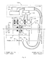
- the EMCVT can provide output in both forward and reverse direction, it may optionally include a reversing gear system coupled at either the main power input or the main output shaft.
- the reversing gear system allows the EMCVT to provide an output in the reverse direction while the components in the electrical and mechanical operate in the same fashion as the forward direction.
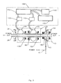
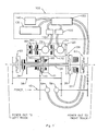
- the electro-mechanical continuously variable transmission (BMCVT) shown in Figure 1 is designed to split power from an input 40 between an electric drive branch 20, using an electric generator 22 and an electric motor 24, and a parallel mechanical drive branch 21, using shafts and/or gears, recombining the power from each branch into a single main output shaft 26.
- a simple planetary gear set 10 as shown in more detail in Figure 2 , consisting of sun gear 12, planet gear(s) 14, carrier 16, and ring gear 18 is used to split power from input 40, derived from an internal combustion engine or other primary power source (not shown), between the electrical drive branch 20 and the mechanical drive branch 21.
- the preferred embodiment is an SRC configuration i.e. sun gear 12 connected to the electrical branch 20, ring gear 18 connected to the mechanical branch 21 and the carrier 16 connected to the input 40 (see Figure 1 ).
- the electrical drive branch consists of a primary generator 22, a primary motor 24, and is connected to an energy storage system 100.
- the energy storage system consists of a battery bank 130, an optional capacitor bank 140, inverters 110 and 120 and a controller 150. Power flow is normally directed between the generator 22 and the motor 24 by a controller 150.
- the inverters 110 and 120 match the differing power characteristics (current, current type, voltage and frequency) of the generator 22, motor 24, battery bank 130 and capacitor bank 140.
- the battery bank 130 may be charged in one of 2 ways: by absorbing power from the input 40 or by absorbing energy from braking.
- the combiner gear set 28 couples the electrical branch 20 to the main output shaft 26.
- the combiner gear set 28 is shown as a pair of spur gears, however, a planetary gear set (as shown in Figures 3 and 4 ) may also be used for more advanced power control systems. Power from the electrical branch 20 is combined with power from the mechanical branch 21 at this point.
- the mechanical drive branch 21 is shown as a simple shaft directly connecting one of the elements of the planetary gear set 10 to the main output shaft 26, but may be a more extensive assembly of shafts and gears to accommodate the physical layout requirements of the transmission.
- the lockup brake 80 selectively connects/disconnects the electrical output element (sun gear 12 in the SRC configuration) of the planetary gear set 10 to ground, preventing that element of the planetary gear set 10 from transmitting any power.
- the generator input clutch 160 selectively connects/disconnects the electrical output element of the planetary gear set 10 to the primary generator 22. Engaging the input clutch 160 to connect the electrical output element (sun gear 12 in the SRC configuration) of planetary gear set 10 also allows the primary generator 22 to absorb power from the planetary gear set 10.
- the generator output clutch 170 selectively connects/disconnects the primary generator 22 to/from the combiner gear set 28. This allows the generator 22 to supplement power provided by the primary motor 24 to the combiner gear set 28.
- the mechanical drive clutch 90 selectively connects/disconnects the mechanical output (ring gear 18 in the SRC configuration) of the planetary gear set 10 to/from the mechanical branch.
- the split speed clutch 180 selectively locks/unlocks two elements of the planetary gear set 10 together preventing any differential speed between the elements. During certain operating modes, it is desirable to lock all three elements (sun 12, ring 18, carrier 16) of the planetary gear set 10 together.
- the split speed clutch 180 is located between the carrier 16 and sun gear 12.
- the clutch 180 may alternatively be located between the sun gear 12 and ring gear 18 or between the ring gear 18 and carrier 16.
- Energizing the split speed clutch 180 locks the carrier 16 and sun gear 12 together. Due to the nature of the planetary gear set 10, the ring gear 18 is forced to turn at the same speed as the other two elements. A reaction torque is now only required at two of the three elements and the planetary gear set 10 is now acting as a rigid coupling between three input/outputs. The ability to lock the planetary gear set 10 in this manner is required for "Burst" mode as well as the engine starting modes described below.
- Incorporating an energy storage system 100 in the electrical 20 branch can increase the performance and efficiency of the transmission in two ways: energy normally lost during braking by conventional mechanical methods may be recovered for later use; and energy stored in the system 100 may be applied to the transmission main output shaft 26 at the same time as peak engine power is applied resulting in a higher power output than is possible with the engine alone.
- the energy normally absorbed by conventional brakes may be directed back through the transmission to the engine (engine braking).
- the motor 24 functions as a generator and the generator 22 functions as a motor.
- Power that normally flows back to the generator 22 may be diverted to the battery bank 130 by the controller 150.
- the battery charge rate or overall capacity may be exceeded. Under these conditions, the excess power can be directed back to the engine or to a capacitor bank 140, which has a much higher charging rate than the battery bank 130.
- energy stored in the capacitor bank 140 may be used to charge the battery bank 130. The various braking procedures are discussed in more detail bellow.
- Power from the battery bank 130 may be used to supplement the power drawn from the engine at input 40 during periods of high demand. Consequently, the engine may be reduced to a more economical size to meet average operating conditions while relatively high performance peaks may still be obtained. This "boost" mode is discussed under forward operating modes below.
- the EMCVT core is shown in, but not limited to, three basic layouts.
- Figure 1 shows a parallel shaft arrangement with two outputs.
- the planetary gear set 10 is arranged coaxially around the main output shaft 26, and the primary generator 22 and primary motor 24 are arranged parallel shaft to the main output shaft 26.
- the input 40 uses a separate parallel shaft.
- the input 40 may alternatively use a shaft perpendicular to the main output shaft 26, driving the input to the planetary gear set 10 through a bevel gear set (not shown).
- the parallel shaft arrangement is suited but not limited to an application where transmission width is an issue but major components may be stacked vertically or front to back. An example would be the drive for a tracked vehicle with limited width between tracks.
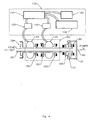
- Figure 3 shows a coaxial shaft arrangement with two outputs and parallel shaft input.
- the components of the electrical 20 and mechanical 21 branches are arranged coaxially around the main output shaft 26, except for energy storage system 100, which is located separately.
- Combiner gear set 28 is a planetary gear set.
- the input 40 uses a shaft parallel to the main output shaft 26.
- the input may alternatively use a shaft perpendicular to the main output shaft 26, driving the input to the planetary gear set 10 through a bevel gear set.
- the coaxial, dual output arrangement is suited but not limited to an application requiring a relatively compact transmission with little or no width limitation. An example would be a front wheel drive vehicle utilizing a transverse engine.
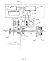
- Figure 4 shows a coaxial shaft arrangement with one output and a coaxial input shaft.
- the components are arranged are in Figure 3 , except that power input 40 is set at one end of main output shaft 26, leaving only one end for output.
- This arrangement creates a long, narrow inline power train suited to long narrow drive bays. An example of this would be a conventional front engine, rear wheel drive vehicle.
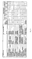
- the operating modes of the transmission are listed in the table in Figure 8 , along with engine, clutch and brake setting for each mode. These modes can be divided into four categories: Forward, Reverse, Braking and Engine Starting.
- the generator output clutch 170 In forward full electrical mode, the generator output clutch 170 is engaged.
- the primary generator 22 and primary motor 24 both function as motors and draw energy stored in the capacitor and battery banks 140, 130. No engine power is drawn from the input 40 and the primary power source (engine) may be allowed to idle or may be shut off completely. This mode is best used for short periods of high torque output such as during initial startup and high acceleration to a higher speed. Electrical mode also drains the capacitor bank 140 and battery bank 130.
- “Burst” mode the engine is in operation and mechanical drive clutch 90, generator output clutch 170 and split speed clutch 180 are all engaged.
- the primary generator 22 and primary motor 24 both function as motors and draw energy stored in the capacitor and battery banks 140, 130.
- Engine power is drawn from input 40 and is delivered directly to the main output shaft 26 through the planetary gear set 10 (with all elements locked by split speed clutch 180) and mechanical drive clutch 90.
- This mode is used to provide a maximum torque output for a short duration (burst) that exceeds that available from the main input 40 alone. Burst mode also drains the capacitor bank 140 and battery bank 130.
- the mechanical drive clutch 90 and generator input clutch 160 are engaged, and the engine is in operation.
- Power provided by the primary power source is drawn from the input 40 of the EMCVT and is split between the mechanical branch 21 and the electrical branch 20. Since the planetary gear set 10 divides input torque according to a fixed ratio, power is split according to the speed of the particular element connected to each branch. Initially, the mechanical branch 21 does not turn as it is directly connected to the main output shaft 26. The primary generator 22 is forced to turn near its upper speed limit. The primary generator 22 produces electrical power that is directed by the controller to the primary motor 24. The primary motor 24 then forces the main output shaft 26 to turn. Adjusting the current/frequency characteristics of the motor 24 and generator 22 varies the effective gear ratio of the electrical branch 20. At the lower half of the EMCVT speed band, power is transferred primarily electrically.
- the speed of the mechanical branch 21 As the output speed increases, so does the speed of the mechanical branch 21. Since input speed is being held constant, the speed of the primary generator 22 must decrease. To do this, the effective gear ratio of the electrical branch 20 is altered by adjusting the current/frequency characteristics to reduce the power supplied by the primary motor 24 to the combiner gear set 28. The net result is that more of the input power is being delivered mechanically and less electrically.
- the primary generator 22 barely turns, producing very low power levels in the electrical branch 20 with power from input 40 being delivered to the main output shaft 26 almost exclusively through the mechanical branch 21. Ideally, the primary generator 22 stops turning completely with only a holding torque generated against the corresponding planetary gear set 10 element. "Full Mechanical" mode, below, discusses how this unique stage of EMCVT operation can be achieved.
- a small amount of electrical power (approximately 10%) can be diverted from the primary motor 24 and used to charge the battery bank 130.
- the stored energy is then available at a later time for other modes of operation as described above.
- Parallel mode is the primary mode of operation for the majority of EMCVT applications and is designed for periods of medium power demands over varying output speed, i.e. conventional driving.
- Parallel mode allows the use of a smaller, more efficient primary power source (engine) to suit cruise power as well as reducing the size of the battery/capacitor bank compared to a conventional (non-parallel) hybrid internal combustion/electric drive.
- Mechanical Mode is an extension of the parallel mode. As stated above, in parallel mode, at the upper end of the EMCVT's speed range, the primary generator 22 barely turns and ideally should stop. Limitations of current motor/generator technology makes it impractical to hold the generator 22 at zero speed.
- a lockup brake 80 is introduced to provide the torque reaction necessary against the planetary gear set 10 by locking the electric output element (sun gear 12 in SRC configurations) to ground, typically the outer casing of the transmission. As a result, the generator 22 is locked out and the mechanical branch 21 is responsible for supplying all the power to the output shaft 26. Otherwise, operation is the same as Parallel mode.
- Mechanical mode is designed for use when the EMCVT is operating near or at maximum speed for a period of time.
- the generator output clutch 170 is engaged as described for forward Electrical mode above. The difference is that the generator 22 and motor 24 are run in reverse to effect reverse output. Electrical mode is used for short periods of reverse operation where high torque is required.
- the mechanical drive clutch 90 and generator input clutch 160 are engaged as described for Forward Parallel mode above.
- Power provided by the primary power source (not shown) is drawn from the input 40 of the EMCVT and is split between the mechanical branch 21 and the electrical branch 20.
- the primary motor 24 is used to reverse the main output shaft 26.
- the element of the planetary gear set 10 connected to the mechanical branch 21 (hence, the main output shaft 26) is forced to turn opposite to its normal (Forward mode) direction.
- the elements of the planetary gear set 10 connected to the input 40 and electrical branch 20 (primary generator 22) turn in the same direction as in Forward mode.
- the resultant negative power flow in the mechanical branch 21 must be compensated for by increasing the power flow in the electrical branch 20.
- the electrical branch 20 must pass a greater amount of power than in forward.
- the components of the electrical branch 20 must either be increased in capacity or reverse must be limited to slow to medium speeds. During this mode, charging of the battery/capacitor banks 130, 140 may take place.
- Parallel mode is the primary operating mode for the reverse direction and may be used for extended periods of reverse operation with medium power demands over varying slow to medium output speed or when little or no energy has been stored in the battery/capacitor banks 130, 140.
- a significant advantage of the EMCVT over conventional transmissions is the use of regenerative braking - the recovery and storage of braking energy for later use.
- Conventional braking (retarding) systems reduce speed by removing kinetic energy from the vehicle or machine and dissipating it as heat. These conventional systems may consist of a mechanical, hydraulic or electromagnetic braking system.
- the EMCVT removes kinetic energy and stores it as electrical/chemical energy in the battery/capacitor banks 130, 140.
- a conventional braking system incorporated into the overall design may be greatly reduced in size since additional braking force can be provided by the transmission. Note that a mechanical braking system is not shown in any of the configurations but may be added if desired.
- the generator input clutch 160 and generator output clutch 170 are engaged.
- the input 40 (engine) does not apply or absorb any power and, in fact, may be shut off.
- Both primary motor 24 and primary generator 22 function as generators charging the battery/capacitor banks 130/140. Large amounts of kinetic energy are absorbed from the transmission main output shaft 26 until the battery/capacitor banks 130/140 are fully charged; braking ability in this mode is limited by the amount of energy that can be absorbed by the banks 130, 140. At that point, either a conventional braking system or Full Engine braking (described below) must be used.
- Maximum regenerative braking is used during short periods of high braking loads such as a panic stop in a vehicle or an emergency shut-off of a stationary machine.
- Light regeneration mode is used during short periods of low to medium braking alternating with "Economy Mode" in Forward or Reverse.
- An example would be a vehicle traveling in "stop and go” traffic.
- Parallel mode is most suitable for, but not limited to, the situation in which braking energy to be absorbed/dissipated exceeds the storage capacity of the battery/capacitor banks 130, 140.
- An example of this would be controlling a heavy vehicle down an unusually steep grade.
- the lockup brake 80 In full engine braking mode, the lockup brake 80 is engaged in addition to mechanical drive clutch 90 and generator input clutch 160. Kinetic energy is absorbed from the transmission main output shaft 26 and dissipated by the engine alone in the same fashion as conventional engine braking. This mode may be applied when the battery/capacitor bank 130, 140 is full and maximum braking is required.
- the duty cycle of the transmission may require cycling through the different modes many times.
- the primary power source engine
- the primary power source should be shut off during modes where it is not required (full electrical and economy modes with regenerative braking). This is especially true if the primary power source happens to be an internal combustion engine. Of course, the primary power source will then need to be started or restarted to enter one of the other operating modes.
- a conventional engine starter motor could be used but it has two major drawbacks: the engine cannot be started near its operating speed and the starter motor does not have the duty cycle required for the high frequency of engine restarts.
- the primary generator 22 as a starting motor for the engine, no extra components are added and the engine can be cranked near its required operating speed, which reduces emissions and increases fuel economy.
- the generator input clutch 160 and split speed clutch 180 are engaged.
- the primary generator 22 functions as a motor, drawing stored energy from the battery/capacitor bank 130, 140. Since all other brakes and clutches are disengaged, the primary generator 22 is able to turn the engine through the planetary gear set 10, which has its elements locked together by the split speed clutch 180. Once the engine is operating, the split speed clutch 180 is disengaged and any of the Forward/Reverse modes engaged.
- the generator input clutch 160 and split speed clutch 180 are engaged.
- the primary generator 22 operates as a starting motor for the engine. Once the engine is operating, the transmission is switched to one of the forward/reverse modes listed in Figure 8 where the engine is on.
- the EMCVT can operate in either Forward or Reverse Parallel mode and use the energy stored in the battery/capacitor bank 130, 140 to maintain power to the main output shaft 26 as well as providing power to start the engine.
- An alternative (not shown) is to place the reverser 190 at the main output shaft 26.
- the result is that the transmission components turn in one direction only regardless of final output direction.
- the major drawback to an output reverser is the higher torque requirements placed on the reverser components compared to a reverser installed at the transmission input 40.
- the resultant increase in size and weight makes the input reverser a better choice. Since the transmission serves to increase the torque available at the transmission input, a reverser installed at the main output shaft 26 must be much stronger than one installed at the input 40. The resulting increase in weight and complexity would make an output reverser unsuitable for the majority of applications.
- a range splitter or doubler may be incorporated at the main output shaft 26 to increase the operating envelope of the transmission.
- Figure 5 shows a parallel shaft EMCVT with a two-speed range splitter based on a planetary gear set 30 and a low-speed 32 and high-speed 34 clutch.
- the two-speed range splitter suits most applications although a three (or more) speed range splitter could also be incorporated if necessary.
- the steering generator 54 is driven either directly by or thru idlers by the input 40 of the transmission.
- the zero shaft 58 is prevented from turning by the steering motor 56 and the outputs of the steering planetaries 60 turn at the same speed. If more power is required to turn one output faster than the other, the steering motor 56 turns the zero shaft 58 in one direction or the other changing the relative speeds of the steering planetary 60 outputs.
- the steering generator 54 may be omitted with power supplied to the steering motor 56 from the battery/capacitor banks 130/140, the primary generator 22, the primary motor 24 or a combination of these elements.
- EMCVT lies in the ability of the configured systems as shown in Figures 1 and 3 to enable a driven output on both ends of the transmission via a common main output shaft 26. This is particularly useful in vehicles or stationary equipment that require duplicated output shafts to two drives such as tracks and/or differentials. Furthermore, one or both of the outputs can be engaged or disengaged eliminating the need for a transfer case when configured for multiple output drives.
- the EMCVT speed can be controlled in any conventional manner, however an electronic control system is preferred to best optimize the power splitting in connection with the output speed when operating in either forward or reverse Parallel mode.
- the electronic control system can also include control means for the optional range splitter and regenerative steering system as well as the various clutches and brakes discussed above.
Abstract
Description
- This invention relates to a drive system useful as a vehicle propulsion system or stationary equipment drive, combining mechanical and electric power systems.
- Electric drive systems have been commonly used for large vehicles or stationary equipment. However, as the output/input speed ratio increases, the electric motor & generator no longer operate at their optimum operating speeds. This reduces the overall efficiency of the drive at the upper half of the drive's operating range. This problem may be overcome by having multiple gear settings to keep the motors and generators operating at or near their optimum speeds, but the complexity of the resulting transmission negates the benefits of using an electric drive.
- An alternative to an electric drive system is a mechanically driven system. However, conventional mechanical drive systems are limited to discrete gear ratios, which do not allow for infinite speed ratios as found in electric drives. A great deal of power management between the engine and the transmission at all output speeds is necessary for transmission effectiveness. A purely mechanical drive is inadequate to ensure the efficient use of the engine's available power due to the discrete speed ratios, while a purely electric drive has inherently lower efficiency at higher operational speeds.
- With the increasing costs of fuel and more stringent emissions requirements, there is a need for more efficient drive systems for large and small vehicles, as well as stationary equipment, to replace traditional electric and mechanical drive systems.
-
U.S. Patent No. 6,592,484 issued to Tsai et al. represents the closest prior art and discloses a parallel hybrid transmission utilizing a compound planetary gear set, two multi-disk clutches and a pair of band clutches operating in a variety of modes. Tsai discloses only a single electric device operating as either a motor or generator mechanically coupled to both sun gears of the compound planetary gear set, hence, simultaneous electrical generation and electrical motoring functions cannot be provided. Although this design may function as a continuously variable transmission between the engine and final drive, it can only do so for a limited time based on battery storage capacity. - Similarly,
U.S. Patent No. 6,428,438 issued to Bowen , Canadian Patent No.2,435,450 issued to Bowen andU.S. Patent No. 5,285,111 issued to Sherman all disclose hybrid systems with a single electrical device functioning either as a motor or a generator. As with the Tsai patent, operational modes are limited by the fact that simultaneous electrical generation and electrical motoring are not possible. -
U.S. Patent No. 5,704,440 issued to Urban et al. discloses a hybrid electric vehicle having a parallel electrical and mechanical system. The electrical system consists of a pair of electric motors mechanically connected to the input of a conventional transmission and a generator connected to one end of the engine output shaft thru a series of pulleys and clutches. The arrangement allows for pure engine, pure electric and electric supplemented engine modes as well as an electro-mechanical series continuously variable transmission mode. The Urban patent lacks a planetary gear set with at least three elements connected to the engine, generator and output and serving to distribute power between the latter 3 components which would allow for a more efficient electro-mechanical continuously variable transmission mode. -
U.S. Patent No. 948,436 issued to Thomas et al. discloses an electro-mechanical continuously variable transmission. Thomas uses a double planetary gear set and a clutch connected to the shaft of the first motor/generator to change from input split/output coupled mode to output split/input coupled mode. In low range, the first motor/generator operates as a generator and the second motor/generator operates as a motor; in high range, the two devices reverse roles. Full vehicle speed range is achieved through these 2 ranges. Since the roles of the components change depending on the speed range, they may not be optimized for performance and efficiency in any one particular range. A better configuration using an input-split / output-coupled layout with a downstream range splitter for low and high range allows the components to be optimized for maximum performance and efficiency. An additonal mode in which both motor/generators drive the vehicle with the engine shut off is not provided in the Thomas patent since an electrical energy storage device and a means for disconnecting the engine from the drive train are not disclosed. Also lacking from the design is a mode allowing engine restart with the vehicle moving. -
U.S. Patent No. 6,371,878 issued to Bowen discloses an electro mechanical continuously variable transmission with a pair of planetary gear sets connected to 2 motor/generators as well as a third motor generator driving an additional output (differential). The compound splitting of power results in one electrical and 2 mechanical paths from the engine to the output. 2 speed ranges are achieved by changing the direction of electrical power flow between first and second ranges requiring switching of motor/generator functions. As with Thomas, 948,436, the components may not be optimized for any one particular range. Bowen discloses a lockup brake for the first motor/generator allowing power to flow purely mechanically, however, the lockup brake is only functional when the first motor/generator is in generator mode i.e. in high range. Bowen does not disclose any features for cycling the engine on and off during vehicle operation. -
U.S. Patent No. 5,558,595 issued to Schmidt et al. discloses a compound-split electro-mechanical continuously variable transmission. As with Thomas 948,436 and Bowen 6,371,878, the roles of the two motor/generators reverse depending on which speed range is desired although the Schmidt patent uses a pair of clutches to change the function of the elements of the compound planetary. Again, this may require compromises in component selection to operated acceptably in low and high range. Schmidt does not disclose a lockup brake to provide a pure mechanical power path but relies on the ability of the first motor/generator to generate power at or near 0 RPM. Without a mechanical locking device, the motor/generator will fail if the vehicle is held at this speed. Finally, Schmidt does not disclose any method of cycling the engine on and off during vehicle operation. -
U.S. Patent No. 6,478,705 issued to Holmes discloses an electrically variable transmission having two planetary gearsets coupled to an engine and two motor/generators. As with Schmidt 5,558,595 and Bowden 6,371,878, the roles of the motor/generators are reversed to provide low and high ranges and, therefore, suffer the similar limitations. Low range configures the planetary sets in an input-split/output coupled system while high range configures the system as a compound split system. Shifting between the two modes occurs at a zero speed point of one of the motor/generators and requires the motor/generator generate power at or near 0 RPM. Since a lockup brake is absent from this design, failure of the motor/generator could result if the vehicle is held at this speed. - Neither Bowen, 6,371,878, Schmidt, 5,558,595, nor Holmes, 6,478,705, disclose a pure electric drive mode in which the engine is off and both motor/generators function as motors drawing power stored from the electrical storage unit for an extended period of time.
- It is an object of this invention to provide a more efficient drive system for large and small vehicles and stationary equipment by combining electric and mechanical power systems. It is a further object of this invention to provide a transmission system for optimizing use of combined drive systems.
- The invention comprises an electro-mechanical continuously variable transmission (EMCVT) that uses a planetary gear system to provide a combination of electric and mechanical power for a vehicle or for stationary equipment. The EMCVT includes a clutch and brake system that allows power from an energy storage unit to be combined with the main power input (typically an engine) to provide a torque output greater than that available from the main power input alone.
- According to the invention, therefore, there is provided a transmisson as defined in
claim 1. The EMCVT may also include a range splitter system to expand the operating parameters of the vehicle or stationary equipment. - The EMCVT may further include a regenerative steering system to control power distribution between the two ends of the main output shaft.
- The EMCVT includes a lockup brake coupled to the electric branch input, operative to lock out the electric branch and force all power through the mechanical branch when the transmission output is operating at a pre-selected percentage of its maximum speed.
- While the EMCVT can provide output in both forward and reverse direction, it may optionally include a reversing gear system coupled at either the main power input or the main output shaft. The reversing gear system allows the EMCVT to provide an output in the reverse direction while the components in the electrical and mechanical operate in the same fashion as the forward direction.
- The invention itself, both as to organization and method of operation, as well as additional objects and advantages thereof, will become readily apparent from the following detailed description when read in connection with the accompanying drawings:
-
Figure 1 shows a block diagram of an EMCVT with two outputs, a parallel shaft configuration, and an SRC planetary gear set; -
Figure 2 shows a simplified diagram of a three-planet planetary gear set; -
Figure 3 shows a block diagram of an EMCVT with two outputs, a coaxial shaft configuration and an SRC planetary gear set; -
Figure 4 shows a block diagram of an EMCVT with one output, a coaxial shaft configuration and an SRC planetary gear set; -
Figure 5 shows a block diagram of the EMCVT ofFigure 1 with a two-speed range doubler; -
Figure 6 shows a block diagram of the EMCVT ofFigure 1 with a regenerative steering system; -
Figure 7 shows a block diagram of the EMCVT ofFigure 1 with a two-speed range doubler and a regenerative steering system; -
Figure 8 shows a table listing the engine, brake and clutch configurations for various operating modes of the EMCVT; and -
Figure 9 shows a block diagram of the EMCVT ofFigure 1 with a geared reverser coupled to the power input. - The electro-mechanical continuously variable transmission (BMCVT) shown in
Figure 1 is designed to split power from aninput 40 between anelectric drive branch 20, using anelectric generator 22 and anelectric motor 24, and a parallelmechanical drive branch 21, using shafts and/or gears, recombining the power from each branch into a singlemain output shaft 26. - A simple planetary gear set 10, as shown in more detail in
Figure 2 , consisting ofsun gear 12, planet gear(s) 14, carrier 16, andring gear 18 is used to split power frominput 40, derived from an internal combustion engine or other primary power source (not shown), between theelectrical drive branch 20 and themechanical drive branch 21. - Although six planetary element combinations are possible, the preferred embodiment is an SRC configuration i.e.
sun gear 12 connected to theelectrical branch 20,ring gear 18 connected to themechanical branch 21 and the carrier 16 connected to the input 40 (seeFigure 1 ). - The electrical drive branch consists of a
primary generator 22, aprimary motor 24, and is connected to anenergy storage system 100. The energy storage system consists of abattery bank 130, anoptional capacitor bank 140,inverters controller 150. Power flow is normally directed between thegenerator 22 and themotor 24 by acontroller 150. Theinverters generator 22,motor 24,battery bank 130 andcapacitor bank 140. Thebattery bank 130 may be charged in one of 2 ways: by absorbing power from theinput 40 or by absorbing energy from braking. - The combiner gear set 28 couples the
electrical branch 20 to themain output shaft 26. The combiner gear set 28 is shown as a pair of spur gears, however, a planetary gear set (as shown inFigures 3 and4 ) may also be used for more advanced power control systems. Power from theelectrical branch 20 is combined with power from themechanical branch 21 at this point. - The
mechanical drive branch 21 is shown as a simple shaft directly connecting one of the elements of the planetary gear set 10 to themain output shaft 26, but may be a more extensive assembly of shafts and gears to accommodate the physical layout requirements of the transmission. - Several brakes and clutches shown in
Figure 1 may be used to control various aspects of the power distribution between the mechanical 21 and electrical 20 branches. Thelockup brake 80 selectively connects/disconnects the electrical output element (sun gear 12 in the SRC configuration) of the planetary gear set 10 to ground, preventing that element of the planetary gear set 10 from transmitting any power. - The
generator input clutch 160 selectively connects/disconnects the electrical output element of the planetary gear set 10 to theprimary generator 22. Engaging theinput clutch 160 to connect the electrical output element (sun gear 12 in the SRC configuration) of planetary gear set 10 also allows theprimary generator 22 to absorb power from the planetary gear set 10. - The
generator output clutch 170 selectively connects/disconnects theprimary generator 22 to/from the combiner gear set 28. This allows thegenerator 22 to supplement power provided by theprimary motor 24 to the combiner gear set 28. - The mechanical drive clutch 90 selectively connects/disconnects the mechanical output (
ring gear 18 in the SRC configuration) of the planetary gear set 10 to/from the mechanical branch. - The
split speed clutch 180 selectively locks/unlocks two elements of the planetary gear set 10 together preventing any differential speed between the elements. During certain operating modes, it is desirable to lock all three elements (sun 12,ring 18, carrier 16) of the planetary gear set 10 together. InFigure 1 , thesplit speed clutch 180 is located between the carrier 16 andsun gear 12. The clutch 180 may alternatively be located between thesun gear 12 andring gear 18 or between thering gear 18 and carrier 16. - Energizing the
split speed clutch 180 locks the carrier 16 andsun gear 12 together. Due to the nature of the planetary gear set 10, thering gear 18 is forced to turn at the same speed as the other two elements. A reaction torque is now only required at two of the three elements and the planetary gear set 10 is now acting as a rigid coupling between three input/outputs. The ability to lock the planetary gear set 10 in this manner is required for "Burst" mode as well as the engine starting modes described below. - Incorporating an
energy storage system 100 in the electrical 20 branch can increase the performance and efficiency of the transmission in two ways: energy normally lost during braking by conventional mechanical methods may be recovered for later use; and energy stored in thesystem 100 may be applied to the transmissionmain output shaft 26 at the same time as peak engine power is applied resulting in a higher power output than is possible with the engine alone. - During periods of low power demand at the
main output shaft 26, some of the power drawn from the engine atinput 40 may be directed to thebattery bank 130 by thecontroller 150 usinggenerator 22 to convert it into electrical power. Engine output power will have to be slightly increased to accommodate the extra power demand. The specific requirements for charging are covered in the discussion of the various operating modes. - During braking operations, the energy normally absorbed by conventional brakes may be directed back through the transmission to the engine (engine braking). The
motor 24 functions as a generator and thegenerator 22 functions as a motor. Power that normally flows back to thegenerator 22 may be diverted to thebattery bank 130 by thecontroller 150. Under heavy or prolonged braking conditions, the battery charge rate or overall capacity may be exceeded. Under these conditions, the excess power can be directed back to the engine or to acapacitor bank 140, which has a much higher charging rate than thebattery bank 130. When braking demands cease, energy stored in thecapacitor bank 140 may be used to charge thebattery bank 130. The various braking procedures are discussed in more detail bellow. - Power from the
battery bank 130 may be used to supplement the power drawn from the engine atinput 40 during periods of high demand. Consequently, the engine may be reduced to a more economical size to meet average operating conditions while relatively high performance peaks may still be obtained. This "boost" mode is discussed under forward operating modes below. - The EMCVT core is shown in, but not limited to, three basic layouts.
-
Figure 1 shows a parallel shaft arrangement with two outputs. The planetary gear set 10 is arranged coaxially around themain output shaft 26, and theprimary generator 22 andprimary motor 24 are arranged parallel shaft to themain output shaft 26. Theinput 40 uses a separate parallel shaft. Theinput 40 may alternatively use a shaft perpendicular to themain output shaft 26, driving the input to the planetary gear set 10 through a bevel gear set (not shown). The parallel shaft arrangement is suited but not limited to an application where transmission width is an issue but major components may be stacked vertically or front to back. An example would be the drive for a tracked vehicle with limited width between tracks. -
Figure 3 shows a coaxial shaft arrangement with two outputs and parallel shaft input. Here the components of the electrical 20 and mechanical 21 branches are arranged coaxially around themain output shaft 26, except forenergy storage system 100, which is located separately. Combiner gear set 28 is a planetary gear set. Theinput 40 uses a shaft parallel to themain output shaft 26. The input may alternatively use a shaft perpendicular to themain output shaft 26, driving the input to the planetary gear set 10 through a bevel gear set. The coaxial, dual output arrangement is suited but not limited to an application requiring a relatively compact transmission with little or no width limitation. An example would be a front wheel drive vehicle utilizing a transverse engine. -
Figure 4 shows a coaxial shaft arrangement with one output and a coaxial input shaft. The components are arranged are inFigure 3 , except thatpower input 40 is set at one end ofmain output shaft 26, leaving only one end for output. This arrangement creates a long, narrow inline power train suited to long narrow drive bays. An example of this would be a conventional front engine, rear wheel drive vehicle. - Referring to
Figure 1 andFigure 8 , several modes of operation are possible but five forward power modes, three reverse power modes and four braking modes are deemed useful. During a typical duty cycle, the transmission may be switched several times between the available modes to optimize efficiency and output power. - The operating modes of the transmission are listed in the table in
Figure 8 , along with engine, clutch and brake setting for each mode. These modes can be divided into four categories: Forward, Reverse, Braking and Engine Starting. - Five modes of operation are available for forward rotation of the output i.e. forward vehicle motion. Not all modes need be available for any given application of the EMCVT.
- In forward full electrical mode, the
generator output clutch 170 is engaged. Theprimary generator 22 andprimary motor 24 both function as motors and draw energy stored in the capacitor andbattery banks input 40 and the primary power source (engine) may be allowed to idle or may be shut off completely. This mode is best used for short periods of high torque output such as during initial startup and high acceleration to a higher speed. Electrical mode also drains thecapacitor bank 140 andbattery bank 130. - In "Burst" mode, the engine is in operation and mechanical drive clutch 90,
generator output clutch 170 and splitspeed clutch 180 are all engaged. Theprimary generator 22 andprimary motor 24 both function as motors and draw energy stored in the capacitor andbattery banks input 40 and is delivered directly to themain output shaft 26 through the planetary gear set 10 (with all elements locked by split speed clutch 180) andmechanical drive clutch 90. This mode is used to provide a maximum torque output for a short duration (burst) that exceeds that available from themain input 40 alone. Burst mode also drains thecapacitor bank 140 andbattery bank 130. - In Economy mode, none of the clutches are engaged. Only the
primary motor 24 is used to power themain output shaft 26. Energy is drawn from capacitor andbattery banks power motor 24. No engine power is drawn from theinput 40 and the primary power source (engine) may be allowed to idle or shut off completely for maximum fuel savings. The duration of operation for this mode is determined by the capacities of battery andcapacitor bank - In parallel mode, the mechanical drive clutch 90 and
generator input clutch 160 are engaged, and the engine is in operation. Power provided by the primary power source is drawn from theinput 40 of the EMCVT and is split between themechanical branch 21 and theelectrical branch 20. Since the planetary gear set 10 divides input torque according to a fixed ratio, power is split according to the speed of the particular element connected to each branch. Initially, themechanical branch 21 does not turn as it is directly connected to themain output shaft 26. Theprimary generator 22 is forced to turn near its upper speed limit. Theprimary generator 22 produces electrical power that is directed by the controller to theprimary motor 24. Theprimary motor 24 then forces themain output shaft 26 to turn. Adjusting the current/frequency characteristics of themotor 24 andgenerator 22 varies the effective gear ratio of theelectrical branch 20. At the lower half of the EMCVT speed band, power is transferred primarily electrically. - As the output speed increases, so does the speed of the
mechanical branch 21. Since input speed is being held constant, the speed of theprimary generator 22 must decrease. To do this, the effective gear ratio of theelectrical branch 20 is altered by adjusting the current/frequency characteristics to reduce the power supplied by theprimary motor 24 to the combiner gear set 28. The net result is that more of the input power is being delivered mechanically and less electrically. - Finally, near the upper end of the EMCVT's speed range, the
primary generator 22 barely turns, producing very low power levels in theelectrical branch 20 with power frominput 40 being delivered to themain output shaft 26 almost exclusively through themechanical branch 21. Ideally, theprimary generator 22 stops turning completely with only a holding torque generated against the corresponding planetary gear set 10 element. "Full Mechanical" mode, below, discusses how this unique stage of EMCVT operation can be achieved. - During intermediate stages of the RPM range, a small amount of electrical power (approximately 10%) can be diverted from the
primary motor 24 and used to charge thebattery bank 130. The stored energy is then available at a later time for other modes of operation as described above. - Parallel mode is the primary mode of operation for the majority of EMCVT applications and is designed for periods of medium power demands over varying output speed, i.e. conventional driving. Parallel mode allows the use of a smaller, more efficient primary power source (engine) to suit cruise power as well as reducing the size of the battery/capacitor bank compared to a conventional (non-parallel) hybrid internal combustion/electric drive.
- Mechanical Mode is an extension of the parallel mode. As stated above, in parallel mode, at the upper end of the EMCVT's speed range, the
primary generator 22 barely turns and ideally should stop. Limitations of current motor/generator technology makes it impractical to hold thegenerator 22 at zero speed. In order to run the EMCVT in full mechanical mode, alockup brake 80 is introduced to provide the torque reaction necessary against the planetary gear set 10 by locking the electric output element (sun gear 12 in SRC configurations) to ground, typically the outer casing of the transmission. As a result, thegenerator 22 is locked out and themechanical branch 21 is responsible for supplying all the power to theoutput shaft 26. Otherwise, operation is the same as Parallel mode. Mechanical mode is designed for use when the EMCVT is operating near or at maximum speed for a period of time. - Three modes of operation are available for reverse rotation of the output. Equivalents to the forward Burst mode and Mechanical mode are not available for reverse operation. Should the full range of forward modes be required for reverse operation, an optional geared reverse may be installed at the
input 40 of the transmission. See "Optional Components" after this section. - The
generator output clutch 170 is engaged as described for forward Electrical mode above. The difference is that thegenerator 22 andmotor 24 are run in reverse to effect reverse output. Electrical mode is used for short periods of reverse operation where high torque is required. - In Economy mode all clutches are disengaged as described for forward Economy mode above. The
primary motor 24 is run in reverse to effect reverse output. Economy mode can be used for short periods of reverse operation with low power demands. - In Parallel mode the mechanical drive clutch 90 and
generator input clutch 160 are engaged as described for Forward Parallel mode above. Power provided by the primary power source (not shown) is drawn from theinput 40 of the EMCVT and is split between themechanical branch 21 and theelectrical branch 20. In order to effect reverse output speed during Parallel mode, theprimary motor 24 is used to reverse themain output shaft 26. The element of the planetary gear set 10 connected to the mechanical branch 21 (hence, the main output shaft 26) is forced to turn opposite to its normal (Forward mode) direction. The elements of the planetary gear set 10 connected to theinput 40 and electrical branch 20 (primary generator 22) turn in the same direction as in Forward mode. Since the torque applied to each of elements of the planetary gear set 10 is in the same direction as in Forward mode, the resultant negative power flow in themechanical branch 21 must be compensated for by increasing the power flow in theelectrical branch 20. For the same output speed in reverse in Parallel mode, theelectrical branch 20 must pass a greater amount of power than in forward. The components of theelectrical branch 20 must either be increased in capacity or reverse must be limited to slow to medium speeds. During this mode, charging of the battery/capacitor banks - Parallel mode is the primary operating mode for the reverse direction and may be used for extended periods of reverse operation with medium power demands over varying slow to medium output speed or when little or no energy has been stored in the battery/
capacitor banks - A significant advantage of the EMCVT over conventional transmissions is the use of regenerative braking - the recovery and storage of braking energy for later use. Conventional braking (retarding) systems reduce speed by removing kinetic energy from the vehicle or machine and dissipating it as heat. These conventional systems may consist of a mechanical, hydraulic or electromagnetic braking system. The EMCVT removes kinetic energy and stores it as electrical/chemical energy in the battery/
capacitor banks - Four braking modes are available depending on the required braking force and state of charge of the battery/
capacitor banks - For maximum regenerative braking, the
generator input clutch 160 andgenerator output clutch 170 are engaged. The input 40 (engine) does not apply or absorb any power and, in fact, may be shut off. Bothprimary motor 24 andprimary generator 22 function as generators charging the battery/capacitor banks 130/140. Large amounts of kinetic energy are absorbed from the transmissionmain output shaft 26 until the battery/capacitor banks 130/140 are fully charged; braking ability in this mode is limited by the amount of energy that can be absorbed by thebanks - Maximum regenerative braking is used during short periods of high braking loads such as a panic stop in a vehicle or an emergency shut-off of a stationary machine.
- For light regenerative braking, none of the clutches are engaged. Energy is handled as described in Maximum Regeneration Mode above except that only the
primary motor 24 functions as a generator. As described above, the battery/capacitor bank - Light regeneration mode is used during short periods of low to medium braking alternating with "Economy Mode" in Forward or Reverse. An example would be a vehicle traveling in "stop and go" traffic.
- In parallel braking mode, the mechanical drive clutch 90 is engaged, resulting in a power split between the
engine input 40 and theelectrical branch 20. As a result, the kinetic energy absorbed from the transmissionmain output shaft 26, can also be split. Part of energy can be converted as described above and stored by the battery/capacitor banks 130/140 and the balance is absorbed/dissipated by the engine (as in conventional engine braking). - Parallel mode is most suitable for, but not limited to, the situation in which braking energy to be absorbed/dissipated exceeds the storage capacity of the battery/
capacitor banks - In full engine braking mode, the
lockup brake 80 is engaged in addition to mechanical drive clutch 90 andgenerator input clutch 160. Kinetic energy is absorbed from the transmissionmain output shaft 26 and dissipated by the engine alone in the same fashion as conventional engine braking. This mode may be applied when the battery/capacitor bank - As mentioned above, the duty cycle of the transmission may require cycling through the different modes many times. In order to realize maximum fuel economy the primary power source (engine) should be shut off during modes where it is not required (full electrical and economy modes with regenerative braking). This is especially true if the primary power source happens to be an internal combustion engine. Of course, the primary power source will then need to be started or restarted to enter one of the other operating modes.
- A conventional engine starter motor could be used but it has two major drawbacks: the engine cannot be started near its operating speed and the starter motor does not have the duty cycle required for the high frequency of engine restarts. By using the
primary generator 22 as a starting motor for the engine, no extra components are added and the engine can be cranked near its required operating speed, which reduces emissions and increases fuel economy. - With the
main output shaft 26 stopped, thegenerator input clutch 160 and splitspeed clutch 180 are engaged. Theprimary generator 22 functions as a motor, drawing stored energy from the battery/capacitor bank primary generator 22 is able to turn the engine through the planetary gear set 10, which has its elements locked together by thesplit speed clutch 180. Once the engine is operating, thesplit speed clutch 180 is disengaged and any of the Forward/Reverse modes engaged. - From a condition where the EMCVT is initially in one of the forward/reverse modes listed in table 1 where the engine is off and
main output shaft 26 is in motion, thegenerator input clutch 160 and splitspeed clutch 180 are engaged. Theprimary generator 22 operates as a starting motor for the engine. Once the engine is operating, the transmission is switched to one of the forward/reverse modes listed inFigure 8 where the engine is on. - Alternatively, the EMCVT can operate in either Forward or Reverse Parallel mode and use the energy stored in the battery/
capacitor bank main output shaft 26 as well as providing power to start the engine. - As stated in the section "Reverse Operation", the full range of forward modes is not normally available in reverse. This suits most conventional vehicles and industrial applications where the performance demand for reverse operation is very low or not required at all. However, some applications may require all forward modes of operation (including all braking modes) in reverse. A simple solution to this problem is to install a geared reverser at either the
input 40 or themain output shaft 26 of the EMCVT. - Placing a
reverser 190 at theinput 40 of the transmission as shown inFigure 9 simply reverses the direction of all the components downstream of theinput 40. Since all speed and torque directions have been reversed, there is no negative power flow through any branch. The transmission will operate using any of the forward modes but with reverse output rotation. - An alternative (not shown) is to place the
reverser 190 at themain output shaft 26. The result is that the transmission components turn in one direction only regardless of final output direction. The major drawback to an output reverser is the higher torque requirements placed on the reverser components compared to a reverser installed at thetransmission input 40. The resultant increase in size and weight makes the input reverser a better choice. Since the transmission serves to increase the torque available at the transmission input, a reverser installed at themain output shaft 26 must be much stronger than one installed at theinput 40. The resulting increase in weight and complexity would make an output reverser unsuitable for the majority of applications. - Due to the limitations of current generator/motor technology, a range splitter or doubler may be incorporated at the
main output shaft 26 to increase the operating envelope of the transmission.Figure 5 shows a parallel shaft EMCVT with a two-speed range splitter based on a planetary gear set 30 and a low-speed 32 and high-speed 34 clutch. The two-speed range splitter suits most applications although a three (or more) speed range splitter could also be incorporated if necessary. - When the EMCVT is used to drive a tracked vehicle with two outputs, precise steering may be accomplished with a regenerative steering system as shown in
Figure 6 . If one output is required to turn slower than the other output, power is transferred from the slower side to the faster side rather than being bled off as heat as in a conventional brake-to steer system. - The
steering generator 54 is driven either directly by or thru idlers by theinput 40 of the transmission. When the power split is equal between outputs, the zeroshaft 58 is prevented from turning by thesteering motor 56 and the outputs of thesteering planetaries 60 turn at the same speed. If more power is required to turn one output faster than the other, thesteering motor 56 turns the zeroshaft 58 in one direction or the other changing the relative speeds of the steering planetary 60 outputs. Alternatively, thesteering generator 54 may be omitted with power supplied to thesteering motor 56 from the battery/capacitor banks 130/140, theprimary generator 22, theprimary motor 24 or a combination of these elements. - Another considerable advantage of the EMCVT lies in the ability of the configured systems as shown in
Figures 1 and3 to enable a driven output on both ends of the transmission via a commonmain output shaft 26. This is particularly useful in vehicles or stationary equipment that require duplicated output shafts to two drives such as tracks and/or differentials. Furthermore, one or both of the outputs can be engaged or disengaged eliminating the need for a transfer case when configured for multiple output drives. - The EMCVT speed can be controlled in any conventional manner, however an electronic control system is preferred to best optimize the power splitting in connection with the output speed when operating in either forward or reverse Parallel mode. Furthermore, the electronic control system can also include control means for the optional range splitter and regenerative steering system as well as the various clutches and brakes discussed above.
- Accordingly, while this invention has been described with reference to illustrative embodiments, this description is not intended to be construed in a limiting sense. Various modifications of the illustrative embodiments, as well as other embodiments of the invention, will be apparent to persons skilled in the art upon reference to this description. It is therefore contemplated that the appended claims will cover any such modifications or embodiments as fall within the scope of the invention.
Claims (9)
- An electro-mechanical continuously variable transmission comprising:(a) an input (40) to receive power from an engine;(b) a main output shaft (26) ;(c) an electric generator (22) ;(d) a planetary gear seat (10) comprising a sun gear (12), a carrier gear (16), and a ring gear (18), wherein a first one of said sun gear (12), carrier (16) and ring gear (18) is coupled to said input (40), and wherein a second one of said sun gear (12), carrier (16) and ring gear (18) is coupled to said main output shaft (26), and wherein the third one of said sun gear (12), carrier (16) and ring gear (18) is coupled to said electric generator (22);(e) an electric motor (24) coupled to said main output shaft (26) by a gear set (28);(f) an energy storage system (100) comprising a battery bank (130), inverters (110), and a controller (150), wherein said energy storage system (100) is coupled to said electric generator (22) and to said electric motor (24), and wherein said energy storage system (100) is operative to accept power from and supply power to said electric generator (22) and said electric motor (24), and wherein power flow is directed between said electric generator (22), said electric motor (24) by said controller, and wherein said battery bank (130) may be charged by absorbing power from said input (40) or by absorbing energy from braking;(g) a split speed clutch (180) coupled to two elements of said planetary gear set (10) and operative to lock said two elements together;(h) a lockup brake (80) coupled to said electric generator (22) and operative to lock said electric generator (22) from rotating;(i) a generator output clutch (170) coupled between said electric generator (22) and said electric motor (24) and operative in a locked mode to lock said generator (22) to said motor (24) ;(j) a mechanical drive clutch (90) coupled between one element of said planetary gear set (10) and said main output shaft (26) and operative to lock together the one element of said planetary gear set (10) to said main output shaft (26) allowing said planetary gear set to split power between said electric generator (22), said input(40) and said main output shaft (26) and;(k) a generator input clutch (160) wherein said engine is in a forward parallel mode of operation when said generator input clutch (160) and said mechanical drive clutch (90) are engaged.
- The transmission of claim 1, further including a range splitter coupled to said main output shaft (26) to enable two or more separate operating ranges for said transmission, said range splitter comprising a second planetary gear set (30), a high-speed clutch (34), and a low-speed clutch (32).
- The transmission of claim 1, further including a regenerative steering system comprising: a steering planetary gear set (60) at each end of said main output shaft (26), a zero shaft (58) operational to rotate in one of two directions, wherein the direction of rotation of said zero shaft (58) controls the relative output speeds of said steering planetary gear sets (60), and a steering motor (56), wherein said steering motor (56) is operable to: i) rotate said zero shaft (58) in one of said two directions, ii) rotate said zero shaft (58) in the other of said two directions, and iii) prevent said zero shaft (58) from rotating.
- The transmission of claim 1, wherein said electric generator (22) and electric motor are arranged around a shaft parallel to said main output shaft (26).
- The transmission of claim 1, wherein said electric generator (22) and electric motor are arranged coaxially around said main output shaft (26).
- The transmission of claim 1, wherein said electric generator (22) and electric motor are arranged coaxially around said main output shaft (26) and said main power input is at one end of said main output shaft (26).
- The transmission of claim 1, further including a reverse gear system coupled to said input (40) operative to reverse the output direction of said transmission.
- The transmission of claim 1, further including a reverse gear system coupled to said main output shaft (26) operative to reverse the output direction of said transmission.
- The transmission of claim 1, wherein when said split speed clutch (180) is engaged with said generator input clutch (160), said electric generator (22) acts as a starting motor and sends power to said input (40).
Applications Claiming Priority (2)
| Application Number | Priority Date | Filing Date | Title |
|---|---|---|---|
| US10/641,137 US7008342B2 (en) | 2003-08-15 | 2003-08-15 | Electro-mechanical continuously variable transmission |
| PCT/CA2004/001518 WO2005017390A1 (en) | 2003-08-15 | 2004-08-16 | Electro-mechanical continuously variable transmission |
Publications (3)
| Publication Number | Publication Date |
|---|---|
| EP1660787A1 EP1660787A1 (en) | 2006-05-31 |
| EP1660787A4 EP1660787A4 (en) | 2010-01-06 |
| EP1660787B1 true EP1660787B1 (en) | 2013-08-14 |
Family
ID=34136264
Family Applications (1)
| Application Number | Title | Priority Date | Filing Date |
|---|---|---|---|
| EP04761682.6A Not-in-force EP1660787B1 (en) | 2003-08-15 | 2004-08-16 | Electro-mechanical continuously variable transmission |
Country Status (8)
| Country | Link |
|---|---|
| US (1) | US7008342B2 (en) |
| EP (1) | EP1660787B1 (en) |
| JP (1) | JP2007502234A (en) |
| KR (1) | KR101120795B1 (en) |
| CN (1) | CN100497997C (en) |
| AU (1) | AU2004265350B2 (en) |
| CA (1) | CA2535647C (en) |
| WO (1) | WO2005017390A1 (en) |
Families Citing this family (36)
| Publication number | Priority date | Publication date | Assignee | Title |
|---|---|---|---|---|
| DE102004028532A1 (en) * | 2004-06-11 | 2006-01-19 | Renk Ag | Device for reversing the steering movement of a steering wheel shaft |
| DE602005012847D1 (en) * | 2005-12-14 | 2009-04-02 | Fondazione Torino Wireless | Electromechanical differential module for a wheeled vehicle and wheeled vehicle with such a differential module |
| EP1998976B1 (en) * | 2006-03-15 | 2012-01-18 | TM4 Inc. | Hybrid transmission for hybrid vehicles |
| US8387738B1 (en) | 2006-08-09 | 2013-03-05 | Sauer-Danfoss Inc. | Electro-mechanical transmission for compact vehicles |
| US7867122B2 (en) * | 2006-09-26 | 2011-01-11 | Epi-Energy Ltd. | Power transmission system with continuously variable speed control |
| DE102007055883A1 (en) * | 2007-12-20 | 2009-06-25 | Forschungsgesellschaft für Zahnräder und Getriebe mbH | Transmission device with at least two output shafts |
| CN101580031A (en) * | 2009-06-29 | 2009-11-18 | 方连军 | Automatic dynamoelectric electric motor car |
| CN101845991A (en) * | 2010-03-25 | 2010-09-29 | 北京理工大学 | Device and method for increasing torque and expanding speed for reciprocating internal combustion engine |
| DE102010063568B4 (en) | 2010-12-20 | 2023-10-05 | Zf Friedrichshafen Ag | Device for driving implements of a commercial vehicle |
| US9039568B2 (en) * | 2012-05-04 | 2015-05-26 | Ford Global Technologies, Llc | Methods and systems for extending regenerative braking |
| US20140266070A1 (en) * | 2013-03-14 | 2014-09-18 | Zvi Kurtzman | Apparatus and Method for Enhancing Battery Life |
| US9939900B2 (en) | 2013-04-26 | 2018-04-10 | Immersion Corporation | System and method for a haptically-enabled deformable surface |
| US10655710B2 (en) | 2013-12-31 | 2020-05-19 | Deere & Company | Multi-mode infinitely variable transmission that provides seamless shifting |
| US10670124B2 (en) | 2013-12-31 | 2020-06-02 | Deere & Company | Multi-mode infinitely variable transmission |
| US10647193B2 (en) | 2014-04-09 | 2020-05-12 | Deere & Company | Multi-mode power trains |
| US10738868B2 (en) | 2014-04-09 | 2020-08-11 | Deere & Company | Multi-mode powertrains |
| US9535550B2 (en) | 2014-11-25 | 2017-01-03 | Immersion Corporation | Systems and methods for deformation-based haptic effects |
| US9783065B2 (en) | 2015-02-04 | 2017-10-10 | Borgwarner Inc. | Energy storage system and method of making and using the same |
| CN105863992B (en) * | 2016-06-15 | 2018-01-12 | 环山集团股份有限公司 | A kind of dual output speed changing type air compressor |
| US10619711B2 (en) | 2017-04-12 | 2020-04-14 | Deere & Company | Infinitely variable transmission with power reverser |
| US11052747B2 (en) | 2018-05-04 | 2021-07-06 | Deere & Company | Multi-mode powertrains |
| US11091018B2 (en) | 2018-05-11 | 2021-08-17 | Deere & Company | Powertrain with variable vertical drop distance |
| DE102018216006A1 (en) * | 2018-09-20 | 2020-03-26 | Robert Bosch Gmbh | Control structure for a mobile work machine, method and work machine |
| US10975959B2 (en) | 2019-04-01 | 2021-04-13 | Deere & Company | Transmission clutch braking control system |
| US11137052B2 (en) | 2019-08-29 | 2021-10-05 | Deere & Company | Transmission assembly with integrated CVP |
| US11351983B2 (en) * | 2019-10-31 | 2022-06-07 | Deere & Company | Power control system with transmission transient boost function |
| US11846085B2 (en) | 2020-02-17 | 2023-12-19 | Deere & Company | Energy management system for a hybrid vehicle with an electrically powered hydraulic system |
| US11325459B2 (en) | 2020-10-09 | 2022-05-10 | Deere & Company | Low profile transmission assembly with integrated CVP |
| US11613246B2 (en) | 2021-01-21 | 2023-03-28 | Deere & Company | Power control system with engine throttle shift function |
| US11628822B2 (en) | 2021-02-09 | 2023-04-18 | Deere & Company | Power control system with stall prevention clutch modulation function |
| US11299141B1 (en) | 2021-02-10 | 2022-04-12 | Deere & Company | System for multi-layer braking and retardation in a work vehicle |
| JP2022150180A (en) * | 2021-03-26 | 2022-10-07 | 株式会社Subaru | Vehicular control device |
| US11820361B2 (en) | 2021-11-30 | 2023-11-21 | Deere & Company | Transmission assembly with electrical machine unit for improved shift quality |
| US11585412B1 (en) | 2021-12-22 | 2023-02-21 | Deere & Company | Electronically-variable, dual-path power shift transmission for work vehicles |
| US11607948B1 (en) | 2021-12-22 | 2023-03-21 | Deere & Company | Electronically-variable power shift transmission for work vehicles |
| US11913528B1 (en) | 2022-10-28 | 2024-02-27 | Deere & Company | Multi-mode continuously variable transmission assembly with drop set arrangement |
Family Cites Families (42)
| Publication number | Priority date | Publication date | Assignee | Title |
|---|---|---|---|---|
| US1307230A (en) | 1919-06-17 | von zweigbergk | ||
| US948436A (en) | 1908-11-05 | 1910-02-08 | John Godfrey Parry Thomas | Power transmission. |
| GB399223A (en) | 1932-04-02 | 1933-10-02 | Morris Ltd Herbert | Apparatus for actuating or controlling electrically operated machines |
| US2050185A (en) | 1934-06-04 | 1936-08-04 | Ray S Kibler | Continuously variable transmission |
| CH280713A (en) | 1945-07-11 | 1952-01-31 | Desmoulins Emile Hyacinthe | Vehicle propulsion installation. |
| US2578837A (en) | 1949-04-19 | 1951-12-18 | William E Raney | Variable-speed drive |
| US3699351A (en) | 1971-08-02 | 1972-10-17 | Gen Motors Corp | Bi-modal vehicles with drive means for external or self-propulsion |
| FR2158000A1 (en) | 1971-10-30 | 1973-06-08 | Berkeley Stephens Hender | |
| JPS55127221A (en) | 1979-03-20 | 1980-10-01 | Daihatsu Motor Co Ltd | Driving system of vehicle |
| US4579019A (en) | 1980-04-04 | 1986-04-01 | Darcy Gabriele | Method and apparatus for power transmission from an engine |
| US4541010A (en) * | 1983-06-17 | 1985-09-10 | Polaroid Corporation | Electronic imaging camera |
| US4779486A (en) | 1987-06-29 | 1988-10-25 | Schumacher Larry L | Rate biased differential gear momentum compensated actuator |
| US5419406A (en) | 1991-10-24 | 1995-05-30 | Aisin Aw Co., Ltd. | Drive system for electric car |
| JP2857535B2 (en) | 1992-05-19 | 1999-02-17 | 株式会社エクォス・リサーチ | Hybrid vehicle |
| US5697466A (en) | 1992-11-12 | 1997-12-16 | Kabushikikaisha Equos Research | Hybrid vehicle |
| GB2275309B (en) | 1993-02-22 | 1997-10-29 | Yang Tai Her | Differential coupling and compounding system |
| US5285111A (en) | 1993-04-27 | 1994-02-08 | General Motors Corporation | Integrated hybrid transmission with inertia assisted launch |
| US5509491A (en) | 1994-04-18 | 1996-04-23 | General Motors Corporation | Dual-motor electric drive system for vehicles |
| JP3042342B2 (en) | 1994-12-28 | 2000-05-15 | 株式会社エクォス・リサーチ | Hybrid vehicle |
| JP2783983B2 (en) | 1995-02-03 | 1998-08-06 | 株式会社エクォス・リサーチ | Hybrid vehicle |
| US5558588A (en) * | 1995-02-16 | 1996-09-24 | General Motors Corporation | Two-mode, input-split, parallel, hybrid transmission |
| US5558595A (en) | 1995-02-17 | 1996-09-24 | General Motors Corporation | One-mode, input-split, parallel, hybrid transmission |
| US5823281A (en) | 1995-05-25 | 1998-10-20 | Kabushikikaisha Equos Reseach | Hybrid vehicle |
| US5704440A (en) | 1995-05-31 | 1998-01-06 | New York Institute Of Technology | Energy distribution method for hydrid electric vehicle |
| US5577973A (en) | 1995-07-20 | 1996-11-26 | General Motors Corporation | Two-mode, split power, electro-mechanical transmission |
| US5558589A (en) | 1995-07-20 | 1996-09-24 | General Motors Corporation | Two-mode, compound-split, electro-mechanical vehicular transmission |
| SE505214C2 (en) | 1995-09-04 | 1997-07-14 | Chandur Sadarangani | hybrid Drive |
| JP3003555B2 (en) | 1995-10-05 | 2000-01-31 | トヨタ自動車株式会社 | Hybrid drive |
| US5730676A (en) * | 1996-10-22 | 1998-03-24 | General Motors Corporation | Three-mode, input-split hybrid transmission |
| US5935035A (en) | 1998-06-24 | 1999-08-10 | General Motors Corporation | Electro-mechanical powertrain |
| US5931757A (en) | 1998-06-24 | 1999-08-03 | General Motors Corporation | Two-mode, compound-split electro-mechanical vehicular transmission |
| US6022287A (en) | 1998-08-19 | 2000-02-08 | General Motors Corporation | Modularly constructed vehicular transmission |
| US6209672B1 (en) | 1998-09-14 | 2001-04-03 | Paice Corporation | Hybrid vehicle |
| US6592484B1 (en) | 1999-08-09 | 2003-07-15 | Gregory A. Schultz | Transmission gearbox for parallel hybrid electric vehicles |
| FR2800331B1 (en) * | 1999-11-03 | 2001-12-28 | Renault | HYBRID DRIVE GROUP COMPRISING AT LEAST TWO EPICYCLOIDAL TRAINS |
| US6405818B1 (en) | 2000-04-11 | 2002-06-18 | Ford Global Technologies, Inc. | Hybrid electric vehicle with limited operation strategy |
| US6358173B1 (en) | 2000-06-12 | 2002-03-19 | General Motors Corporation | Two-mode, compound-split, electro-mechanical vehicular transmission having significantly reduced vibrations |
| US6428438B1 (en) | 2000-07-26 | 2002-08-06 | New Venture Gear, Inc. | Hybrid automated manual transmission |
| US6371878B1 (en) | 2000-08-22 | 2002-04-16 | New Venture Gear, Inc. | Electric continuously variable transmission |
| US6464608B2 (en) | 2001-02-08 | 2002-10-15 | New Venture Gear Inc. | Transfer case for hybrid vehicle |
| US6478705B1 (en) | 2001-07-19 | 2002-11-12 | General Motors Corporation | Hybrid electric powertrain including a two-mode electrically variable transmission |
| US6551208B1 (en) * | 2001-10-18 | 2003-04-22 | General Motors Corporation | Three-mode, compound-split, electrically-variable transmission |
-
2003
- 2003-08-15 US US10/641,137 patent/US7008342B2/en not_active Expired - Fee Related
-
2004
- 2004-08-16 CA CA2535647A patent/CA2535647C/en not_active Expired - Fee Related
- 2004-08-16 JP JP2006522865A patent/JP2007502234A/en active Pending
- 2004-08-16 EP EP04761682.6A patent/EP1660787B1/en not_active Not-in-force
- 2004-08-16 KR KR1020067003166A patent/KR101120795B1/en not_active IP Right Cessation
- 2004-08-16 WO PCT/CA2004/001518 patent/WO2005017390A1/en active Application Filing
- 2004-08-16 AU AU2004265350A patent/AU2004265350B2/en not_active Ceased
- 2004-08-16 CN CNB2004800260944A patent/CN100497997C/en not_active Expired - Fee Related
Also Published As
| Publication number | Publication date |
|---|---|
| US7008342B2 (en) | 2006-03-07 |
| JP2007502234A (en) | 2007-02-08 |
| EP1660787A1 (en) | 2006-05-31 |
| AU2004265350B2 (en) | 2010-04-29 |
| AU2004265350A1 (en) | 2005-02-24 |
| CA2535647C (en) | 2010-05-11 |
| CN100497997C (en) | 2009-06-10 |
| US20050035601A1 (en) | 2005-02-17 |
| CA2535647A1 (en) | 2005-02-24 |
| CN1849469A (en) | 2006-10-18 |
| EP1660787A4 (en) | 2010-01-06 |
| WO2005017390A1 (en) | 2005-02-24 |
| KR101120795B1 (en) | 2012-03-23 |
| KR20060070547A (en) | 2006-06-23 |
Similar Documents
| Publication | Publication Date | Title |
|---|---|---|
| EP1660787B1 (en) | Electro-mechanical continuously variable transmission | |
| US9845088B2 (en) | Torque overlay device for a hybrid drive system, and a method for operating such a hybrid drive system | |
| CN100419310C (en) | Powertrain including input disconnect and accessory drive system for an electrically variable transmission | |
| US7214154B2 (en) | Electrically variable transmission having six fixed speed ratios | |
| US7963874B2 (en) | Dual mode EVT with input split reverse mode | |
| CN102085795A (en) | Hybrid driving system of vehicle clutch and power coupling synchronizer combined gear shift | |
| KR20060052339A (en) | Split serial-parallel hybrid dual-power drive system | |
| CN108116218B (en) | Multi-gear series-parallel driving system based on planetary gear train | |
| US11724585B2 (en) | Two motor power-split hybrid system with selectable one-way clutch enabled lockable planetary gear sets for two-speed dual motor EV and engine plus dual motor drive modes | |
| US8226516B2 (en) | Electric torque converter with dual-driven main pump | |
| CN111114284B (en) | Power split hybrid power coupling system and vehicle | |
| EP3640068A1 (en) | Series-parallel hybrid power system and vehicle comprising same | |
| Yang et al. | Integrated electro-mechanical transmission systems in hybrid electric vehicles | |
| CN111452608A (en) | Hybrid power transmission and electric drive device based on compound planetary gear train | |
| CN103009994A (en) | Power coupling device and transmission system of hybrid power vehicle | |
| JP4400676B2 (en) | Hybrid vehicle drive system | |
| CN111319449A (en) | Hybrid power coupling system and vehicle | |
| JP2000016101A (en) | Hybrid vehicle | |
| CN111376699A (en) | Hybrid power coupling system and vehicle | |
| WO2020259518A1 (en) | Battery electric vehicle and electric drive power system therefor | |
| CN111319450B (en) | Hybrid power driving system and automobile | |
| CN113602075A (en) | Power system of vehicle and vehicle | |
| CN106151418B (en) | Electric continuously variable transmission and vehicle including the same | |
| CN111016617A (en) | Planet row hybrid power system and vehicle | |
| CN111376700B (en) | Hybrid power coupling system and vehicle |
Legal Events
| Date | Code | Title | Description |
|---|---|---|---|
| PUAI | Public reference made under article 153(3) epc to a published international application that has entered the european phase |
Free format text: ORIGINAL CODE: 0009012 |
|
| 17P | Request for examination filed |
Effective date: 20060311 |
|
| AK | Designated contracting states |
Kind code of ref document: A1 Designated state(s): AT BE BG CH CY CZ DE DK EE ES FI FR GB GR HU IE IT LI LU MC NL PL PT RO SE SI SK TR |
|
| DAX | Request for extension of the european patent (deleted) | ||
| A4 | Supplementary search report drawn up and despatched |
Effective date: 20091208 |
|
| 17Q | First examination report despatched |
Effective date: 20100903 |
|
| GRAP | Despatch of communication of intention to grant a patent |
Free format text: ORIGINAL CODE: EPIDOSNIGR1 |
|
| RIC1 | Information provided on ipc code assigned before grant |
Ipc: B60K 6/365 20071001ALI20130301BHEP Ipc: F16H 3/72 20060101AFI20130301BHEP Ipc: B60K 6/445 20071001ALI20130301BHEP Ipc: B60K 6/387 20071001ALI20130301BHEP |
|
| GRAS | Grant fee paid |
Free format text: ORIGINAL CODE: EPIDOSNIGR3 |
|
| GRAA | (expected) grant |
Free format text: ORIGINAL CODE: 0009210 |
|
| AK | Designated contracting states |
Kind code of ref document: B1 Designated state(s): AT BE BG CH CY CZ DE DK EE ES FI FR GB GR HU IE IT LI LU MC NL PL PT RO SE SI SK TR |
|
| REG | Reference to a national code |
Ref country code: GB Ref legal event code: FG4D |
|
| REG | Reference to a national code |
Ref country code: CH Ref legal event code: EP Ref country code: AT Ref legal event code: REF Ref document number: 627046 Country of ref document: AT Kind code of ref document: T Effective date: 20130815 |
|
| REG | Reference to a national code |
Ref country code: IE Ref legal event code: FG4D |
|
| REG | Reference to a national code |
Ref country code: DE Ref legal event code: R096 Ref document number: 602004043041 Country of ref document: DE Effective date: 20131010 |
|
| REG | Reference to a national code |
Ref country code: SE Ref legal event code: TRGR |
|
| REG | Reference to a national code |
Ref country code: NL Ref legal event code: VDEP Effective date: 20130814 Ref country code: AT Ref legal event code: MK05 Ref document number: 627046 Country of ref document: AT Kind code of ref document: T Effective date: 20130814 |
|
| PG25 | Lapsed in a contracting state [announced via postgrant information from national office to epo] |
Ref country code: AT Free format text: LAPSE BECAUSE OF FAILURE TO SUBMIT A TRANSLATION OF THE DESCRIPTION OR TO PAY THE FEE WITHIN THE PRESCRIBED TIME-LIMIT Effective date: 20130814 Ref country code: PT Free format text: LAPSE BECAUSE OF FAILURE TO SUBMIT A TRANSLATION OF THE DESCRIPTION OR TO PAY THE FEE WITHIN THE PRESCRIBED TIME-LIMIT Effective date: 20131216 Ref country code: CY Free format text: LAPSE BECAUSE OF FAILURE TO SUBMIT A TRANSLATION OF THE DESCRIPTION OR TO PAY THE FEE WITHIN THE PRESCRIBED TIME-LIMIT Effective date: 20130710 |
|
| PG25 | Lapsed in a contracting state [announced via postgrant information from national office to epo] |
Ref country code: BE Free format text: LAPSE BECAUSE OF FAILURE TO SUBMIT A TRANSLATION OF THE DESCRIPTION OR TO PAY THE FEE WITHIN THE PRESCRIBED TIME-LIMIT Effective date: 20130814 Ref country code: SI Free format text: LAPSE BECAUSE OF FAILURE TO SUBMIT A TRANSLATION OF THE DESCRIPTION OR TO PAY THE FEE WITHIN THE PRESCRIBED TIME-LIMIT Effective date: 20130814 Ref country code: FI Free format text: LAPSE BECAUSE OF FAILURE TO SUBMIT A TRANSLATION OF THE DESCRIPTION OR TO PAY THE FEE WITHIN THE PRESCRIBED TIME-LIMIT Effective date: 20130814 Ref country code: GR Free format text: LAPSE BECAUSE OF FAILURE TO SUBMIT A TRANSLATION OF THE DESCRIPTION OR TO PAY THE FEE WITHIN THE PRESCRIBED TIME-LIMIT Effective date: 20131115 Ref country code: PL Free format text: LAPSE BECAUSE OF FAILURE TO SUBMIT A TRANSLATION OF THE DESCRIPTION OR TO PAY THE FEE WITHIN THE PRESCRIBED TIME-LIMIT Effective date: 20130814 |
|
| PG25 | Lapsed in a contracting state [announced via postgrant information from national office to epo] |
Ref country code: CY Free format text: LAPSE BECAUSE OF FAILURE TO SUBMIT A TRANSLATION OF THE DESCRIPTION OR TO PAY THE FEE WITHIN THE PRESCRIBED TIME-LIMIT Effective date: 20130814 |
|
| REG | Reference to a national code |
Ref country code: CH Ref legal event code: PL |
|
| PG25 | Lapsed in a contracting state [announced via postgrant information from national office to epo] |
Ref country code: CZ Free format text: LAPSE BECAUSE OF FAILURE TO SUBMIT A TRANSLATION OF THE DESCRIPTION OR TO PAY THE FEE WITHIN THE PRESCRIBED TIME-LIMIT Effective date: 20130814 Ref country code: CH Free format text: LAPSE BECAUSE OF NON-PAYMENT OF DUE FEES Effective date: 20130831 Ref country code: LI Free format text: LAPSE BECAUSE OF NON-PAYMENT OF DUE FEES Effective date: 20130831 Ref country code: NL Free format text: LAPSE BECAUSE OF FAILURE TO SUBMIT A TRANSLATION OF THE DESCRIPTION OR TO PAY THE FEE WITHIN THE PRESCRIBED TIME-LIMIT Effective date: 20130814 Ref country code: RO Free format text: LAPSE BECAUSE OF FAILURE TO SUBMIT A TRANSLATION OF THE DESCRIPTION OR TO PAY THE FEE WITHIN THE PRESCRIBED TIME-LIMIT Effective date: 20130814 Ref country code: SK Free format text: LAPSE BECAUSE OF FAILURE TO SUBMIT A TRANSLATION OF THE DESCRIPTION OR TO PAY THE FEE WITHIN THE PRESCRIBED TIME-LIMIT Effective date: 20130814 Ref country code: DK Free format text: LAPSE BECAUSE OF FAILURE TO SUBMIT A TRANSLATION OF THE DESCRIPTION OR TO PAY THE FEE WITHIN THE PRESCRIBED TIME-LIMIT Effective date: 20130814 Ref country code: EE Free format text: LAPSE BECAUSE OF FAILURE TO SUBMIT A TRANSLATION OF THE DESCRIPTION OR TO PAY THE FEE WITHIN THE PRESCRIBED TIME-LIMIT Effective date: 20130814 |
|
| REG | Reference to a national code |
Ref country code: IE Ref legal event code: MM4A |
|
| PG25 | Lapsed in a contracting state [announced via postgrant information from national office to epo] |
Ref country code: ES Free format text: LAPSE BECAUSE OF FAILURE TO SUBMIT A TRANSLATION OF THE DESCRIPTION OR TO PAY THE FEE WITHIN THE PRESCRIBED TIME-LIMIT Effective date: 20130814 Ref country code: MC Free format text: LAPSE BECAUSE OF FAILURE TO SUBMIT A TRANSLATION OF THE DESCRIPTION OR TO PAY THE FEE WITHIN THE PRESCRIBED TIME-LIMIT Effective date: 20130814 |
|
| PLBE | No opposition filed within time limit |
Free format text: ORIGINAL CODE: 0009261 |
|
| STAA | Information on the status of an ep patent application or granted ep patent |
Free format text: STATUS: NO OPPOSITION FILED WITHIN TIME LIMIT |
|
| 26N | No opposition filed |
Effective date: 20140515 |
|
| PG25 | Lapsed in a contracting state [announced via postgrant information from national office to epo] |
Ref country code: IE Free format text: LAPSE BECAUSE OF NON-PAYMENT OF DUE FEES Effective date: 20130816 |
|
| REG | Reference to a national code |
Ref country code: DE Ref legal event code: R097 Ref document number: 602004043041 Country of ref document: DE Effective date: 20140515 |
|
| PG25 | Lapsed in a contracting state [announced via postgrant information from national office to epo] |
Ref country code: TR Free format text: LAPSE BECAUSE OF FAILURE TO SUBMIT A TRANSLATION OF THE DESCRIPTION OR TO PAY THE FEE WITHIN THE PRESCRIBED TIME-LIMIT Effective date: 20130814 |
|
| PG25 | Lapsed in a contracting state [announced via postgrant information from national office to epo] |
Ref country code: HU Free format text: LAPSE BECAUSE OF FAILURE TO SUBMIT A TRANSLATION OF THE DESCRIPTION OR TO PAY THE FEE WITHIN THE PRESCRIBED TIME-LIMIT; INVALID AB INITIO Effective date: 20040816 Ref country code: BG Free format text: LAPSE BECAUSE OF FAILURE TO SUBMIT A TRANSLATION OF THE DESCRIPTION OR TO PAY THE FEE WITHIN THE PRESCRIBED TIME-LIMIT Effective date: 20130814 Ref country code: LU Free format text: LAPSE BECAUSE OF NON-PAYMENT OF DUE FEES Effective date: 20130816 |
|
| REG | Reference to a national code |
Ref country code: FR Ref legal event code: ST Effective date: 20160429 Ref country code: FR Ref legal event code: PLFP Year of fee payment: 12 |
|
| REG | Reference to a national code |
Ref country code: FR Ref legal event code: RN Effective date: 20160616 |
|
| REG | Reference to a national code |
Ref country code: FR Ref legal event code: FC Effective date: 20160622 |
|
| REG | Reference to a national code |
Ref country code: FR Ref legal event code: PLFP Year of fee payment: 13 |
|
| PG25 | Lapsed in a contracting state [announced via postgrant information from national office to epo] |
Ref country code: FR Free format text: LAPSE BECAUSE OF NON-PAYMENT OF DUE FEES Effective date: 20150831 |
|
| PGFP | Annual fee paid to national office [announced via postgrant information from national office to epo] |
Ref country code: IT Payment date: 20160825 Year of fee payment: 13 Ref country code: GB Payment date: 20160818 Year of fee payment: 13 Ref country code: DE Payment date: 20160818 Year of fee payment: 13 |
|
| PGFP | Annual fee paid to national office [announced via postgrant information from national office to epo] |
Ref country code: FR Payment date: 20160818 Year of fee payment: 13 Ref country code: SE Payment date: 20160818 Year of fee payment: 13 |
|
| PGRI | Patent reinstated in contracting state [announced from national office to epo] |
Ref country code: FR Effective date: 20160622 |
|
| REG | Reference to a national code |
Ref country code: DE Ref legal event code: R119 Ref document number: 602004043041 Country of ref document: DE |
|
| GBPC | Gb: european patent ceased through non-payment of renewal fee |
Effective date: 20170816 |
|
| PG25 | Lapsed in a contracting state [announced via postgrant information from national office to epo] |
Ref country code: SE Free format text: LAPSE BECAUSE OF NON-PAYMENT OF DUE FEES Effective date: 20170817 |
|
| REG | Reference to a national code |
Ref country code: FR Ref legal event code: ST Effective date: 20180430 |
|
| PG25 | Lapsed in a contracting state [announced via postgrant information from national office to epo] |
Ref country code: DE Free format text: LAPSE BECAUSE OF NON-PAYMENT OF DUE FEES Effective date: 20180301 Ref country code: GB Free format text: LAPSE BECAUSE OF NON-PAYMENT OF DUE FEES Effective date: 20170816 |
|
| PG25 | Lapsed in a contracting state [announced via postgrant information from national office to epo] |
Ref country code: IT Free format text: LAPSE BECAUSE OF NON-PAYMENT OF DUE FEES Effective date: 20170816 Ref country code: FR Free format text: LAPSE BECAUSE OF NON-PAYMENT OF DUE FEES Effective date: 20170831 |