EP1663014B1 - Suture sever tube - Google Patents
Suture sever tube Download PDFInfo
- Publication number
- EP1663014B1 EP1663014B1 EP04754671A EP04754671A EP1663014B1 EP 1663014 B1 EP1663014 B1 EP 1663014B1 EP 04754671 A EP04754671 A EP 04754671A EP 04754671 A EP04754671 A EP 04754671A EP 1663014 B1 EP1663014 B1 EP 1663014B1
- Authority
- EP
- European Patent Office
- Prior art keywords
- tube
- suture
- lever arm
- lumen
- cutting
- Prior art date
- Legal status (The legal status is an assumption and is not a legal conclusion. Google has not performed a legal analysis and makes no representation as to the accuracy of the status listed.)
- Not-in-force
Links
Images


Classifications
-
- A—HUMAN NECESSITIES
- A61—MEDICAL OR VETERINARY SCIENCE; HYGIENE
- A61B—DIAGNOSIS; SURGERY; IDENTIFICATION
- A61B17/00—Surgical instruments, devices or methods, e.g. tourniquets
- A61B17/04—Surgical instruments, devices or methods, e.g. tourniquets for suturing wounds; Holders or packages for needles or suture materials
- A61B17/0467—Instruments for cutting sutures
-
- A—HUMAN NECESSITIES
- A61—MEDICAL OR VETERINARY SCIENCE; HYGIENE
- A61B—DIAGNOSIS; SURGERY; IDENTIFICATION
- A61B17/00—Surgical instruments, devices or methods, e.g. tourniquets
- A61B17/04—Surgical instruments, devices or methods, e.g. tourniquets for suturing wounds; Holders or packages for needles or suture materials
- A61B17/0469—Suturing instruments for use in minimally invasive surgery, e.g. endoscopic surgery
-
- A—HUMAN NECESSITIES
- A61—MEDICAL OR VETERINARY SCIENCE; HYGIENE
- A61B—DIAGNOSIS; SURGERY; IDENTIFICATION
- A61B17/00—Surgical instruments, devices or methods, e.g. tourniquets
- A61B17/32—Surgical cutting instruments
- A61B17/320016—Endoscopic cutting instruments, e.g. arthroscopes, resectoscopes
-
- A—HUMAN NECESSITIES
- A61—MEDICAL OR VETERINARY SCIENCE; HYGIENE
- A61B—DIAGNOSIS; SURGERY; IDENTIFICATION
- A61B17/00—Surgical instruments, devices or methods, e.g. tourniquets
- A61B17/00234—Surgical instruments, devices or methods, e.g. tourniquets for minimally invasive surgery
- A61B2017/00292—Surgical instruments, devices or methods, e.g. tourniquets for minimally invasive surgery mounted on or guided by flexible, e.g. catheter-like, means
-
- A—HUMAN NECESSITIES
- A61—MEDICAL OR VETERINARY SCIENCE; HYGIENE
- A61B—DIAGNOSIS; SURGERY; IDENTIFICATION
- A61B17/00—Surgical instruments, devices or methods, e.g. tourniquets
- A61B17/0057—Implements for plugging an opening in the wall of a hollow or tubular organ, e.g. for sealing a vessel puncture or closing a cardiac septal defect
- A61B2017/00575—Implements for plugging an opening in the wall of a hollow or tubular organ, e.g. for sealing a vessel puncture or closing a cardiac septal defect for closure at remote site, e.g. closing atrial septum defects
- A61B2017/00606—Implements H-shaped in cross-section, i.e. with occluders on both sides of the opening
-
- A—HUMAN NECESSITIES
- A61—MEDICAL OR VETERINARY SCIENCE; HYGIENE
- A61B—DIAGNOSIS; SURGERY; IDENTIFICATION
- A61B17/00—Surgical instruments, devices or methods, e.g. tourniquets
- A61B17/0057—Implements for plugging an opening in the wall of a hollow or tubular organ, e.g. for sealing a vessel puncture or closing a cardiac septal defect
- A61B2017/00575—Implements for plugging an opening in the wall of a hollow or tubular organ, e.g. for sealing a vessel puncture or closing a cardiac septal defect for closure at remote site, e.g. closing atrial septum defects
- A61B2017/00623—Introducing or retrieving devices therefor
-
- A—HUMAN NECESSITIES
- A61—MEDICAL OR VETERINARY SCIENCE; HYGIENE
- A61B—DIAGNOSIS; SURGERY; IDENTIFICATION
- A61B17/00—Surgical instruments, devices or methods, e.g. tourniquets
- A61B17/28—Surgical forceps
- A61B17/29—Forceps for use in minimally invasive surgery
- A61B2017/2901—Details of shaft
- A61B2017/2905—Details of shaft flexible
Definitions
- the invention relates to medical instruments for cutting sutures in general and more particularly to devices for cutting sutures remotely such as sutures secured to an intracardiac septal occluder implanted in a patient by a percutaneous route.
- Sutures as components of a percutaneous delivery system, can provide the system with a method to remotely control an implant, such as an intracardiac septal occluder, during implantation. Since it is not uncommon for a delivery system to be 1.2m (four feet) long or more in order to traverse a vessel, any suture that might extend through the delivery system would be at least as long. In a case where this suture needs to be released from the implant to which it is tethered following remote placement of the implant, it would be undesirable and possibly disruptive to the implant's integrity and position, to disengage the suture by unthreading an entire four feet of suture through the implant. A more desirable, and less disruptive approach, might be to remotely sever the suture, adjacent to the implant, to allow for efficient unthreading of a shorter section of the suture from the implant.
- an implant such as an intracardiac septal occluder
- DE-A-4314463 discloses a device for endoscopic suture cutting including a first tube (trocar) and a second tube to which a pivoting blade is mounted at the distal end.
- the invention generally relates to an apparatus for intracardiac cutting of a suture as in appended claim 1. More particularly, an apparatus for cutting sutures remotely such as sutures secured to an intracardiac septal occluder implanted in a patient by a percutaneous route.
- the invention relates to a suture cutting apparatus including a distal cutting end and a proximal control end.
- the distal cutting end further includes a first tube defining a lumen, and a second tube, located and slideably movable within the lumen of the first tube, the second tube defining a lumen and further including a cutting edge.
- the apparatus includes a lever arm having a proximal end and a distal end, and a second tube with a slot for receiving the lever arm.
- the lever arm contains a pivot positioned on the lever arm.
- the lever arm is pivotably attached to the distal cutting end of the second tube.
- the lever arm is flexibly attached to the distal cutting end of the second tube.
- the cross section of the lever arm is generally U-shaped.
- the cutting edge may be positioned on the distal end of the lever arm.
- the lever arm is parallel to the longitudinal axis of the second tube while the lever arm is located within the lumen of the first tube, and forms an angle relative to the longitudinal axis of the second tube while the lever arm is outside the lumen of the first tube. The angle is in the range of 0-90°.
- the cutting edge is angled towards the longitudinal axis of the second tube.
- the cutting edge is substantially perpendicular to the longitudinal axis of the second tube.
- the cutting edge may be replaceable.
- the apparatus includes a return guide.
- the return guide may be positioned on the lever arm and slideably movable within the first tube.
- the apparatus includes a catheter.
- Figure 1 is a schematic of the apparatus with a cutaway schematic of the first tube according to an illustrative embodiment of the invention.
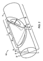
- Figure 2 is a perspective schematic of the second tube at the distal cutting end of the apparatus shown in Figure 1 including a slot and a lever arm according to an illustrative embodiment of the invention.
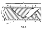
- Figure 3 is an illustrative schematic of the apparatus including a cutaway of the first tube at the distal cutting end to illustrate the lever arm with a cutting edge shown in Figure 1 according to one illustrative embodiment of the invention.
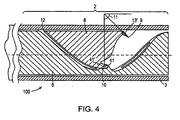
- Figure 4 is an illustrative schematic of the apparatus including a cutaway of the first tube at the distal cutting end to illustrate the lever arm with a cutting edge shown in Figure 1 according to another illustrative embodiment of the invention.
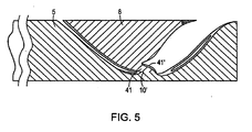
- Figure 5 is an illustrative schematic of the lever arm including a pivot according to another illustrative embodiment of the invention.
- Figure 6 is an illustrative cutaway schematic of the first tube at the distal cutting end of the apparatus shown in Figure 1 including a second tube advanced distally from the first lumen of the first tube according to an illustrative embodiment of the invention.
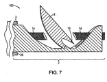
- Figure 7 is a cutaway schematic of the first tube at the distal cutting end of the apparatus shown in Figure 1 including the lever arm in a cutting position and a severed suture according to an illustrative embodiment of the invention.
- Figure 8 is a cutaway schematic of the first tube at the distal cutting end of the apparatus shown in Figure 1 including a return guide in an open position according to an illustrative embodiment of the invention.
- Figure 9 is a cutaway schematic of the first tube at the distal cutting end of the apparatus shown in Figure 1 including a return guide in a collapsed position according to an illustrative embodiment of the invention.
- Figure 10 is a perspective schematic of the apparatus of Figure 1 including a septal occluder with the distal cutting end of the apparatus positioned in the right atrium of the heart according to an illustrative embodiment of the invention.
- the present invention pertains to an apparatus for cutting a suture.
- the apparatus may be used to deliver implants, e.g., intracardiac occluders, for example, intracardiac septal occluders manufactured by NMT Medical Inc., Boston, MA.
- Intracardiac occluders are used to repair congenital or acquired defects in the heart or the major blood vessels, thereof, including interatrial septal shunts, such as a patent foramen ovale, interventricular septal shunts, patent ductus arteriosus and aortic-pulmonary window.
- FIG. 1 is an illustrative schematic of the apparatus 100 with a cutaway schematic of the first tube according to an illustrative embodiment of the invention.
- the invention relates to an apparatus for remotely severing a suture.
- the exemplary apparatus 100 for cutting a suture includes a proximal control end 1 and a distal cutting end 2.
- the proximal control end 1 is the end proximal to the operator and used to control the distal cutting end 2.
- the apparatus 100 also includes a first tube 3, a second tube 5, a lever arm 8, a cutting edge 13, and a pivot 10.
- the distal cutting end further includes a return guide (not shown) and/or a spring mechanism (not shown).
- the distal cutting end 2 of the apparatus 100 for remotely cutting a suture includes a portion of the first tube 3 including a first lumen 4.
- a second tube 5 is longitudinally disposed within the first lumen 4 of the first tube 3.
- the second tube 5 includes a longitudinally disposed lumen 6 extending from the proximal control end 1 of the apparatus 100 to the distal cutting end 2 of the apparatus 100.
- the second tube 5 is slidably moveable within the first lumen 4 of the first tube 3.
- the first tube 3 is generally elongated and has an external diameter sufficiently sized, e.g., a diameter 0.03inm and a length approximately 150cm, to allow the first tube 3 to be delivered percutaneously via a vessel to an anatomical site, for example, the atrial septum, in a patient.
- the first lumen 4 is hollow, typically cylindrically shaped, and has an internal diameter slightly larger than the external diameter of the second tube 5 to allow the second tube 5 to slide within the first lumen 4.
- the second tube 5 is elongated and has an internal diameter sized to allow the hollow and cylindrical second lumen 6 to pass a suture, for example, single 0 catgut, polyethylene or nylon suture.
- the second tube 5 also contains a slot 7 sized and shaped to receive the lever arm 8 pivotably attached to the second tube 5.
- the first tube 3 is longitudinally and slidably disposed within a catheter 18.
- the first tube 3 serves as the catheter 18.
- Materials for construction of the apparatus include but are not limited to polyethylene block copolymer (Pebax®), polytetrafluoroethylene (PTFE), metals such as stainless steel, a ceramic, or a composite material.
- Figure 2 is a perspective schematic of the second tube 5 at the distal cutting end 2 of the apparatus 100 including the slot 7 and the lever arm 8 according to an illustrative embodiment of the invention.
- the illustrative second tube 5 is a cylindrical tube including a central longitudinal axis 30.
- the second tube 5 includes two planes, plane 31 and plane 32, perpendicularly intersecting the central longitudinal axis 30 and perpendicular to each other.
- the slot 7 is a longitudinal defect in the wall 33 of the second tube 5.
- the slot 7 extends through the entire thickness of the wall 33 to the second lumen 6.
- the slot 7 is substantially symmetrical about the plane 31 which longitudinally bisects the slot 7.
- the length 35 of the slot 7 is in the range of about 0.5mm to 10mm, or 1mm to 3mm, preferably.
- the maximum width 36 of the slot 7 is generally equivalent to the external diameter of the second tube.
- the slot 7 is sized and shaped to receive the lever arm 8.
- the illustrative lever arm 8 is generally an inverted U shape in a traverse section, wedge-shaped when viewed from the side, and substantially symmetrical about plane 31.
- the lever arm 8 pivots about a pivot 10.
- the axis 34 of the pivot 10 is perpendicular to the axis 30 and parallel to the plane 32.
- the top 40 of the wedge-shaped illustrative lever arm 8 in a collapsed position is parallel to the longitudinal axis 30 of the second tube 5 and is flush with the outer wall 33 of the second tube 5.
- FIG 3 is an illustrative schematic of the apparatus 100 including a cutaway of the first tube 3 at the distal cutting end 2 to illustrate the lever arm 8 with a cutting edge 13 shown in Figure 1 according to one illustrative embodiment of the invention.
- the lever arm 8 pivots about the pivot 10.
- the top 40 of the wedge-shaped illustrative lever arm 8 is positioned parallel to the longitudinal axis 30 of the second tube 5 and is flush with the outer wall 33 of the second tube 5.
- the lever arm 8 includes the pivot 10, a lever arm proximal end 12, and a lever arm distal end 9.
- a cutting edge 13 is positioned on the top 40 of the lever arm 8 at the lever arm distal end 9 of the lever arm 8.
- the cutting edge 13 is a straight edge blade.
- the cutting edge 13 is tooth-like or pointed such that the cutting edge 13 may pierce and/or fracture a suture.
- Figure 4 is an illustrative schematic of the apparatus 100 including a cutaway of the first tube 3 at the distal cutting end 2 to illustrate the lever arm 8 with a cutting edge 13' shown in Figure 1 according to another illustrative embodiment of the invention.
- the illustrative cutting edge 13' biases downward in the direction of the pivot 10 at an angle 11 of about 0 to 90 degrees, preferably about 45 degrees from a line perpendicular to the longitudinal axis of the second tube 5.
- the lever arm 8 includes a pivot 10 according to one illustrative embodiment of the invention.
- the illustrative pivot 10 pivotably connects the lever arm 8 to the second tube 5.
- the pivot 10 with two ends 41, 41' is a transverse rod that passes through a solid portion of the second tube 5 connecting the pivot ends 41, 41' of the lever arm 8 to the second tube 5.
- the pivot 10 may be located anywhere along the longitudinal axis of the lever arm 8 between the lever arm proximal end 12 and the lever arm distal end 9, preferably located approximately halfway between the lever arm proximal end 12 and the lever arm distal end 9.
- Figure 5 is an illustrative schematic of the lever arm 8 including a pivot 10' according to another illustrative embodiment of the invention.
- the illustrative pivot 10' pivotably connects the lever arm 8 to the second tube 5.
- the pivot 10' is a flexible material connecting the pivot ends 41, 41' of the lever arm 8 to the second tube 5 allowing the lever arm 8 to pivot by flexing the flexible material of the pivot 10'.
- Figure 6 is an illustrative cutaway schematic of the first tube 3 at the distal cutting end 2 of the apparatus 100 including either a second tube 5 advanced distally from the first lumen 4 of the first tube 3 or alternatively the first tube 3 and first lumen 4 retracted proximally from the second tube 5 according to an illustrative embodiment of the invention.
- the illustrative slot 7 and the lever arm 8 are extended beyond the distal end 20 of the first tube 3.
- the slot 7 is sized and shaped to allow the cutting edge 13 to pivot as indicated by arrow 21 into the second lumen 6 of the second tube 5.
- a biasing mechanism urges the lever arm distal end 9 of the lever arm 8 to move from a collapsed position, shown in phantom, to an open position across the longitudinal axis 30 of the second lumen 6.
- the desired angle 11 of the lever arm 8 relative to a vertical axis perpendicular to the longitudinal axis 30 of the device 100 is in the range of about 0 degrees to about 90 degrees, preferably 45 degrees. As the lever arm 8 pivots on the pivot 10, the lever arm proximal end 12 lifts out of the second lumen 6.
- Figure 7 is a schematic of the first tube 3 at the distal cutting end 2 of the apparatus 100 including the lever arm 8 in a cutting position extended distally beyond the distal end 20 of the first tube 3, and a severed suture 14 cut by the cutting edge 13 of the lever arm 8 according to an illustrative embodiment of the invention.
- the illustrative cutting edge 13 cuts the suture 14 into two separate segments.
- Figure 8 is a cutaway schematic of the first tube 3 at the distal cutting end 2 of the apparatus 100 including a return guide 15 in an open position with the lever arm 8 in a cutting position extended distally beyond the distal end 20 of the first tube 3 according to an illustrative embodiment of the invention.
- the return guide 15 is a wire loop as illustrated in Figure 9 .
- the wire loop 15 includes two ends 50, 51 joined to the proximal end 12 of the lever arm 8 and an apex 52 that extends proximally from the two loop ends 50, 51.
- the wire loop 15 includes a bend 53.
- the proximal end 12 of the lever arm 8 returns to a collapsed position enclosed within the slot 7.
- Figure 9 is a schematic of the first tube 3 at the distal cutting end 2 of the apparatus 100 including a return guide 15 in the collapsed position according to an illustrative embodiment of the invention.
- the invention may be used in a method for introducing an implant, such as a septal defect occluder, to an anatomical site in a patient for example, for implanting a septal occluder to occlude a patent foramen ovale.
- an implant such as a septal defect occluder
- Figure 10 is an illustrative schematic of the apparatus 100 including a septal occluder 17.
- the distal cutting end 2 of the apparatus 100 is positioned in the right atrium 54 of the heart.
- the proximal control end 1 is used by an operator to guide the occluder 17 into position at the patent foramen ovale. Once the occluder 17 is positioned as desired, the operator manipulates the control end 1 to urge the second tube 5 distally, or, alternatively, the first tube 3 proximally until the slot 7 and lever arm 8 are extended beyond the distal end 20 of the first tube 3.
- the cutting edge 13 of the lever arm distal end 9 engages the suture 14.
- Proximal retraction of the suture 14 draws the suture 14 against the cutting edge 13 thereby severing the suture 14.
- engagement of the cutting edge 13' with the suture 14 fractures the suture 14 such that it may be segmented with minimal tension applied to the suture 14 by the operator.
- the short end of the suture 14 is unthreaded from the occluder 17 and drawn through the catheter 18 towards the proximal control end 1.
- the short length of the segmented suture 14 that extends from the distal cutting end 2 to the occluder 17 is drawn through the occluder 17.
Abstract
Description
- The invention relates to medical instruments for cutting sutures in general and more particularly to devices for cutting sutures remotely such as sutures secured to an intracardiac septal occluder implanted in a patient by a percutaneous route.
- Sutures, as components of a percutaneous delivery system, can provide the system with a method to remotely control an implant, such as an intracardiac septal occluder, during implantation. Since it is not uncommon for a delivery system to be 1.2m (four feet) long or more in order to traverse a vessel, any suture that might extend through the delivery system would be at least as long. In a case where this suture needs to be released from the implant to which it is tethered following remote placement of the implant, it would be undesirable and possibly disruptive to the implant's integrity and position, to disengage the suture by unthreading an entire four feet of suture through the implant. A more desirable, and less disruptive approach, might be to remotely sever the suture, adjacent to the implant, to allow for efficient unthreading of a shorter section of the suture from the implant.
-
DE-A-4314463 discloses a device for endoscopic suture cutting including a first tube (trocar) and a second tube to which a pivoting blade is mounted at the distal end. - The invention generally relates to an apparatus for intracardiac cutting of a suture as in appended claim 1. More particularly, an apparatus for cutting sutures remotely such as sutures secured to an intracardiac septal occluder implanted in a patient by a percutaneous route.
- The invention relates to a suture cutting apparatus including a distal cutting end and a proximal control end. The distal cutting end further includes a first tube defining a lumen, and a second tube, located and slideably movable within the lumen of the first tube, the second tube defining a lumen and further including a cutting edge.
- In a particular embodiment, the apparatus includes a lever arm having a proximal end and a distal end, and a second tube with a slot for receiving the lever arm. In a further embodiment of the apparatus, the lever arm contains a pivot positioned on the lever arm. In one embodiment, the lever arm is pivotably attached to the distal cutting end of the second tube. Alternatively, the lever arm is flexibly attached to the distal cutting end of the second tube. In one embodiment of the apparatus including a lever arm, the cross section of the lever arm is generally U-shaped.
- In a further embodiment of the apparatus including a lever arm, the cutting edge may be positioned on the distal end of the lever arm. In still another embodiment, the lever arm is parallel to the longitudinal axis of the second tube while the lever arm is located within the lumen of the first tube, and forms an angle relative to the longitudinal axis of the second tube while the lever arm is outside the lumen of the first tube. The angle is in the range of 0-90°. In one embodiment, while the lever arm is outside the lumen of the first tube, the cutting edge is angled towards the longitudinal axis of the second tube. Alternatively, the cutting edge is substantially perpendicular to the longitudinal axis of the second tube. In yet another embodiment of the apparatus, the cutting edge may be replaceable.
- In still another embodiment, the apparatus includes a return guide. The return guide may be positioned on the lever arm and slideably movable within the first tube.
- In a further embodiment, the apparatus includes a catheter.
- The aspects of the invention presented above and many of the accompanying advantages of the present invention will become better understood by referring to the included drawings, which show a system according to the invention and in which:
-
Figure 1 is a schematic of the apparatus with a cutaway schematic of the first tube according to an illustrative embodiment of the invention. -
Figure 2 is a perspective schematic of the second tube at the distal cutting end of the apparatus shown inFigure 1 including a slot and a lever arm according to an illustrative embodiment of the invention. -
Figure 3 is an illustrative schematic of the apparatus including a cutaway of the first tube at the distal cutting end to illustrate the lever arm with a cutting edge shown inFigure 1 according to one illustrative embodiment of the invention. -
Figure 4 is an illustrative schematic of the apparatus including a cutaway of the first tube at the distal cutting end to illustrate the lever arm with a cutting edge shown inFigure 1 according to another illustrative embodiment of the invention. -
Figure 5 is an illustrative schematic of the lever arm including a pivot according to another illustrative embodiment of the invention. -
Figure 6 is an illustrative cutaway schematic of the first tube at the distal cutting end of the apparatus shown inFigure 1 including a second tube advanced distally from the first lumen of the first tube according to an illustrative embodiment of the invention. -
Figure 7 is a cutaway schematic of the first tube at the distal cutting end of the apparatus shown inFigure 1 including the lever arm in a cutting position and a severed suture according to an illustrative embodiment of the invention. -
Figure 8 is a cutaway schematic of the first tube at the distal cutting end of the apparatus shown inFigure 1 including a return guide in an open position according to an illustrative embodiment of the invention. -
Figure 9 is a cutaway schematic of the first tube at the distal cutting end of the apparatus shown inFigure 1 including a return guide in a collapsed position according to an illustrative embodiment of the invention. -
Figure 10 is a perspective schematic of the apparatus ofFigure 1 including a septal occluder with the distal cutting end of the apparatus positioned in the right atrium of the heart according to an illustrative embodiment of the invention. - The present invention pertains to an apparatus for cutting a suture. The apparatus may be used to deliver implants, e.g., intracardiac occluders, for example, intracardiac septal occluders manufactured by NMT Medical Inc., Boston, MA. Intracardiac occluders are used to repair congenital or acquired defects in the heart or the major blood vessels, thereof, including interatrial septal shunts, such as a patent foramen ovale, interventricular septal shunts, patent ductus arteriosus and aortic-pulmonary window.
-
Figure 1 is an illustrative schematic of theapparatus 100 with a cutaway schematic of the first tube according to an illustrative embodiment of the invention. In one aspect, the invention relates to an apparatus for remotely severing a suture. Theexemplary apparatus 100 for cutting a suture includes a proximal control end 1 and adistal cutting end 2. The proximal control end 1 is the end proximal to the operator and used to control thedistal cutting end 2. Theapparatus 100 also includes afirst tube 3, asecond tube 5, alever arm 8, acutting edge 13, and apivot 10. In some embodiments, according to the invention, the distal cutting end further includes a return guide (not shown) and/or a spring mechanism (not shown). - The
distal cutting end 2 of theapparatus 100 for remotely cutting a suture includes a portion of thefirst tube 3 including afirst lumen 4. Asecond tube 5 is longitudinally disposed within thefirst lumen 4 of thefirst tube 3. Thesecond tube 5 includes a longitudinally disposedlumen 6 extending from the proximal control end 1 of theapparatus 100 to thedistal cutting end 2 of theapparatus 100. Thesecond tube 5 is slidably moveable within thefirst lumen 4 of thefirst tube 3. Thefirst tube 3 is generally elongated and has an external diameter sufficiently sized, e.g., a diameter 0.03inm and a length approximately 150cm, to allow thefirst tube 3 to be delivered percutaneously via a vessel to an anatomical site, for example, the atrial septum, in a patient. Thefirst lumen 4 is hollow, typically cylindrically shaped, and has an internal diameter slightly larger than the external diameter of thesecond tube 5 to allow thesecond tube 5 to slide within thefirst lumen 4. Thesecond tube 5 is elongated and has an internal diameter sized to allow the hollow and cylindricalsecond lumen 6 to pass a suture, for example, single 0 catgut, polyethylene or nylon suture. Thesecond tube 5 also contains aslot 7 sized and shaped to receive thelever arm 8 pivotably attached to thesecond tube 5. In one embodiment, thefirst tube 3 is longitudinally and slidably disposed within acatheter 18. In another embodiment, thefirst tube 3 serves as thecatheter 18. Materials for construction of the apparatus include but are not limited to polyethylene block copolymer (Pebax®), polytetrafluoroethylene (PTFE), metals such as stainless steel, a ceramic, or a composite material. -
Figure 2 is a perspective schematic of thesecond tube 5 at thedistal cutting end 2 of theapparatus 100 including theslot 7 and thelever arm 8 according to an illustrative embodiment of the invention. In one embodiment, the illustrativesecond tube 5 is a cylindrical tube including a centrallongitudinal axis 30. Thesecond tube 5 includes two planes,plane 31 andplane 32, perpendicularly intersecting the centrallongitudinal axis 30 and perpendicular to each other. In one embodiment, theslot 7 is a longitudinal defect in thewall 33 of thesecond tube 5. In one embodiment, theslot 7 extends through the entire thickness of thewall 33 to thesecond lumen 6. In one embodiment, theslot 7 is substantially symmetrical about theplane 31 which longitudinally bisects theslot 7. Thelength 35 of theslot 7 is in the range of about 0.5mm to 10mm, or 1mm to 3mm, preferably. Themaximum width 36 of theslot 7 is generally equivalent to the external diameter of the second tube. Theslot 7 is sized and shaped to receive thelever arm 8. - The
illustrative lever arm 8 is generally an inverted U shape in a traverse section, wedge-shaped when viewed from the side, and substantially symmetrical aboutplane 31. Thelever arm 8 pivots about apivot 10. Theaxis 34 of thepivot 10 is perpendicular to theaxis 30 and parallel to theplane 32. The top 40 of the wedge-shapedillustrative lever arm 8 in a collapsed position is parallel to thelongitudinal axis 30 of thesecond tube 5 and is flush with theouter wall 33 of thesecond tube 5. -
Figure 3 is an illustrative schematic of theapparatus 100 including a cutaway of thefirst tube 3 at thedistal cutting end 2 to illustrate thelever arm 8 with acutting edge 13 shown inFigure 1 according to one illustrative embodiment of the invention. Thelever arm 8 pivots about thepivot 10. The top 40 of the wedge-shapedillustrative lever arm 8 is positioned parallel to thelongitudinal axis 30 of thesecond tube 5 and is flush with theouter wall 33 of thesecond tube 5. Thelever arm 8 includes thepivot 10, a lever armproximal end 12, and a lever armdistal end 9. Acutting edge 13 is positioned on the top 40 of thelever arm 8 at the lever armdistal end 9 of thelever arm 8. In one embodiment, illustrated inFigure 3 , thecutting edge 13 is a straight edge blade. Alternatively, thecutting edge 13 is tooth-like or pointed such that thecutting edge 13 may pierce and/or fracture a suture. -
Figure 4 is an illustrative schematic of theapparatus 100 including a cutaway of thefirst tube 3 at thedistal cutting end 2 to illustrate thelever arm 8 with a cutting edge 13' shown inFigure 1 according to another illustrative embodiment of the invention. The illustrative cutting edge 13' biases downward in the direction of thepivot 10 at anangle 11 of about 0 to 90 degrees, preferably about 45 degrees from a line perpendicular to the longitudinal axis of thesecond tube 5. - With continued reference to
Figure 4 , thelever arm 8 includes apivot 10 according to one illustrative embodiment of the invention. Theillustrative pivot 10 pivotably connects thelever arm 8 to thesecond tube 5. In one embodiment, thepivot 10 with two ends 41, 41' is a transverse rod that passes through a solid portion of thesecond tube 5 connecting the pivot ends 41, 41' of thelever arm 8 to thesecond tube 5. Thepivot 10 may be located anywhere along the longitudinal axis of thelever arm 8 between the lever armproximal end 12 and the lever armdistal end 9, preferably located approximately halfway between the lever armproximal end 12 and the lever armdistal end 9. -
Figure 5 is an illustrative schematic of thelever arm 8 including a pivot 10' according to another illustrative embodiment of the invention. The illustrative pivot 10' pivotably connects thelever arm 8 to thesecond tube 5. In one embodiment, the pivot 10' is a flexible material connecting the pivot ends 41, 41' of thelever arm 8 to thesecond tube 5 allowing thelever arm 8 to pivot by flexing the flexible material of the pivot 10'. -
Figure 6 is an illustrative cutaway schematic of thefirst tube 3 at thedistal cutting end 2 of theapparatus 100 including either asecond tube 5 advanced distally from thefirst lumen 4 of thefirst tube 3 or alternatively thefirst tube 3 andfirst lumen 4 retracted proximally from thesecond tube 5 according to an illustrative embodiment of the invention. Theillustrative slot 7 and thelever arm 8 are extended beyond thedistal end 20 of thefirst tube 3. Theslot 7 is sized and shaped to allow thecutting edge 13 to pivot as indicated byarrow 21 into thesecond lumen 6 of thesecond tube 5. A biasing mechanism, such asspring 56, urges the lever armdistal end 9 of thelever arm 8 to move from a collapsed position, shown in phantom, to an open position across thelongitudinal axis 30 of thesecond lumen 6. The desiredangle 11 of thelever arm 8 relative to a vertical axis perpendicular to thelongitudinal axis 30 of thedevice 100 is in the range of about 0 degrees to about 90 degrees, preferably 45 degrees. As thelever arm 8 pivots on thepivot 10, the lever armproximal end 12 lifts out of thesecond lumen 6. -
Figure 7 is a schematic of thefirst tube 3 at thedistal cutting end 2 of theapparatus 100 including thelever arm 8 in a cutting position extended distally beyond thedistal end 20 of thefirst tube 3, and a severedsuture 14 cut by thecutting edge 13 of thelever arm 8 according to an illustrative embodiment of the invention. Theillustrative cutting edge 13 cuts thesuture 14 into two separate segments. -
Figure 8 is a cutaway schematic of thefirst tube 3 at thedistal cutting end 2 of theapparatus 100 including areturn guide 15 in an open position with thelever arm 8 in a cutting position extended distally beyond thedistal end 20 of thefirst tube 3 according to an illustrative embodiment of the invention. In one embodiment, thereturn guide 15 is a wire loop as illustrated inFigure 9 . Thewire loop 15 includes two ends 50, 51 joined to theproximal end 12 of thelever arm 8 and an apex 52 that extends proximally from the two loop ends 50, 51. Thewire loop 15 includes abend 53. As thesecond tube 5 is withdrawn into thefirst tube 3, or thefirst tube 3 is advanced distally over thesecond tube 5, the apex 52 of thewire loop 15 slides into thelumen 4 of thefirst tube 3. As thedistal end 20 of thefirst tube 3 provides the necessary force to compress thewire loop 15 thereby minimizing thebend 53 in thewire loop 15, theproximal end 12 of thelever arm 8 returns to a collapsed position enclosed within theslot 7. -
Figure 9 is a schematic of thefirst tube 3 at thedistal cutting end 2 of theapparatus 100 including areturn guide 15 in the collapsed position according to an illustrative embodiment of the invention. - The invention may be used in a method for introducing an implant, such as a septal defect occluder, to an anatomical site in a patient for example, for implanting a septal occluder to occlude a patent foramen ovale.
-
Figure 10 is an illustrative schematic of theapparatus 100 including aseptal occluder 17. Thedistal cutting end 2 of theapparatus 100 is positioned in theright atrium 54 of the heart. The proximal control end 1 is used by an operator to guide theoccluder 17 into position at the patent foramen ovale. Once theoccluder 17 is positioned as desired, the operator manipulates the control end 1 to urge thesecond tube 5 distally, or, alternatively, thefirst tube 3 proximally until theslot 7 andlever arm 8 are extended beyond thedistal end 20 of thefirst tube 3. Thecutting edge 13 of the lever armdistal end 9 engages thesuture 14. Proximal retraction of thesuture 14 draws thesuture 14 against the cuttingedge 13 thereby severing thesuture 14. Alternatively, if the cutting edge 13' illustrated inFigure 4 is used, engagement of the cutting edge 13' with thesuture 14 fractures thesuture 14 such that it may be segmented with minimal tension applied to thesuture 14 by the operator. - Once the
occluder 17 is in place as desired and thesuture 14 is severed, the short end of thesuture 14 is unthreaded from theoccluder 17 and drawn through thecatheter 18 towards the proximal control end 1. As such, rather than drawing the entire length of thesuture 14 that extends from the proximal control end 1 to theoccluder 17, only the short length of the segmentedsuture 14 that extends from thedistal cutting end 2 to theoccluder 17 is drawn through theoccluder 17. - Although the present invention has been described with reference to the preferred embodiments, workers skilled in the art will recognize that changes may be made in form and detail with departing from the scope of the invention, as defined by the following claims.
Claims (10)
- A device for intracardiac cutting of a suture comprising:a distal cutting end section (2) and a proximal control end (1);a first tube (3) extending from said proximal end to said distal end section (2) and defining a first lumen (4);a second tube (5) extending from said proximal end to said distal end section (2), located and slidingly movable within said first lumen (4), said second tube defining a second lumen (6) for slidingly receiving a suture (14); anda pivoting blade (8) located on the distal end section of the second tube and attached to the second tube at a pivot (10, 10'), said pivoting blade including at its distal end a cutting edge (13);the pivoting blade (8) being constrained to a first state when within the first tube (3), and being biased to a second state in the absence of such constraint, the second state being rotated through an angle about the pivot (10,10'), such that the cutting edge (13) encroaches on the second lumen (6) thereby cutting the suture (14) as the suture (14) is pulled through the second lumen (6).
- The apparatus of claim 1, wherein said second tube (5) contains a slot (7) for receiving said pivoting blade (8).
- The apparatus of claim 1, wherein:a) said pivoting blade (8) is pivotably attached to said distal cutting end section (2) of said second tube (5); orb) said pivoting blade (8) is flexibly attached to said distal cutting end section (2) of said second tube (5).
- The apparatus of claim 1, wherein a top of said pivoting blade (8) is parallel to a longitudinal axis of said second tube (5) when said pivoting blade (8) is located within the first lumen (4) of said first tube (3).
- The apparatus of claim 1, wherein:a) said angle about the pivot of said pivoting blade (8) is in the range of 0-90°; orb) said cutting edge (13) of said pivoting blade (8) is angled towards the longitudinal axis of said second tube (5); orc) said cutting edge (13) of said pivoting blade (8) is substantially perpendicular to the longitudinal axis of said second tube (5).
- The apparatus of claim 1, wherein a cross section of the pivoting blade (8) is generally U shaped.
- The apparatus of claim 1 further comprising a return guide (15).
- The apparatus of claim 1:a) further comprising a return guide (15) positioned on said pivoting blade (8); and in which case optionally wherein said return guide (15) is slidingly movable within said first tube (3); orb) said cutting edge (13) is replaceable; orc) further comprising a catheter and a suture (14) joined to an intracardiac septal occluder.
- The apparatus of claim 1, further comprising a suture (14) joined to an intracardiac septal occluder.
- The apparatus of claim 9, wherein said intracardiac septal occluder is suitable for a patent foramen ovale.
Applications Claiming Priority (2)
| Application Number | Priority Date | Filing Date | Title |
|---|---|---|---|
| US50194903P | 2003-09-11 | 2003-09-11 | |
| PCT/US2004/018119 WO2005034767A1 (en) | 2003-09-11 | 2004-06-08 | Suture sever tube |
Publications (2)
| Publication Number | Publication Date |
|---|---|
| EP1663014A1 EP1663014A1 (en) | 2006-06-07 |
| EP1663014B1 true EP1663014B1 (en) | 2008-08-13 |
Family
ID=34434835
Family Applications (1)
| Application Number | Title | Priority Date | Filing Date |
|---|---|---|---|
| EP04754671A Not-in-force EP1663014B1 (en) | 2003-09-11 | 2004-06-08 | Suture sever tube |
Country Status (7)
| Country | Link |
|---|---|
| US (1) | US7473260B2 (en) |
| EP (1) | EP1663014B1 (en) |
| JP (1) | JP2007504886A (en) |
| AT (1) | ATE404126T1 (en) |
| CA (1) | CA2538707A1 (en) |
| DE (1) | DE602004015807D1 (en) |
| WO (1) | WO2005034767A1 (en) |
Cited By (1)
| Publication number | Priority date | Publication date | Assignee | Title |
|---|---|---|---|---|
| CN107307895A (en) * | 2017-07-07 | 2017-11-03 | 陕西日日新生物科技有限公司 | A kind of instrument in patent foramen ovale edge formation wound face |
Families Citing this family (27)
| Publication number | Priority date | Publication date | Assignee | Title |
|---|---|---|---|---|
| US6488689B1 (en) | 1999-05-20 | 2002-12-03 | Aaron V. Kaplan | Methods and apparatus for transpericardial left atrial appendage closure |
| US7338514B2 (en) * | 2001-06-01 | 2008-03-04 | St. Jude Medical, Cardiology Division, Inc. | Closure devices, related delivery methods and tools, and related methods of use |
| US7976564B2 (en) | 2002-05-06 | 2011-07-12 | St. Jude Medical, Cardiology Division, Inc. | PFO closure devices and related methods of use |
| US8372112B2 (en) * | 2003-04-11 | 2013-02-12 | St. Jude Medical, Cardiology Division, Inc. | Closure devices, related delivery methods, and related methods of use |
| US20040267306A1 (en) * | 2003-04-11 | 2004-12-30 | Velocimed, L.L.C. | Closure devices, related delivery methods, and related methods of use |
| JP5074765B2 (en) * | 2003-10-09 | 2012-11-14 | センターハート・インコーポレイテッド | Apparatus and method for tissue ligation |
| CA2596249C (en) | 2005-01-27 | 2013-12-10 | Wilson-Cook Medical, Inc. | Endoscopic cutting device |
| WO2006110734A2 (en) | 2005-04-07 | 2006-10-19 | Sentreheart, Inc. | Apparatus and method for the ligation of tissue |
| EP1716810B1 (en) * | 2005-04-26 | 2008-10-15 | Niti-on Co., Ltd. | Endoscopic surgical instrument |
| US7837619B2 (en) * | 2005-08-19 | 2010-11-23 | Boston Scientific Scimed, Inc. | Transeptal apparatus, system, and method |
| US8062309B2 (en) * | 2005-08-19 | 2011-11-22 | Boston Scientific Scimed, Inc. | Defect occlusion apparatus, system, and method |
| US7766906B2 (en) * | 2005-08-19 | 2010-08-03 | Boston Scientific Scimed, Inc. | Occlusion apparatus |
| US7824397B2 (en) * | 2005-08-19 | 2010-11-02 | Boston Scientific Scimed, Inc. | Occlusion apparatus |
| US7998095B2 (en) * | 2005-08-19 | 2011-08-16 | Boston Scientific Scimed, Inc. | Occlusion device |
| EP2929842B1 (en) | 2007-03-30 | 2019-06-12 | Sentreheart, Inc. | Devices and sytems for closing the left atrial appendage |
| US8469983B2 (en) | 2007-09-20 | 2013-06-25 | Sentreheart, Inc. | Devices and methods for remote suture management |
| EP3488797B1 (en) * | 2009-04-01 | 2021-06-23 | Sentreheart, Inc. | Tissue ligation devices and controls therefor |
| WO2011129893A1 (en) | 2010-04-13 | 2011-10-20 | Sentreheart, Inc. | Methods and devices for treating atrial fibrillation |
| EP2415404B1 (en) * | 2010-08-06 | 2017-08-30 | Tornier, Inc. | Arthroscopic device for cutting a suture and arthroscopic surgical kit including such a device |
| EP2717791B1 (en) | 2011-06-08 | 2018-05-09 | Sentreheart, Inc. | Tissue ligation devices and tensioning devices therefor |
| US9980719B2 (en) * | 2013-03-12 | 2018-05-29 | St. Jude Medical Puerto Rico Llc | Non-invasive suture cutter and related methods for cutting a suture below the skin |
| EP2967534B1 (en) | 2013-03-12 | 2018-04-25 | Sentreheart, Inc. | Tissue ligation devices |
| US11284878B2 (en) * | 2013-08-22 | 2022-03-29 | Anchor Orthopedics Xt Inc. | Suture cutter |
| EP4226881A1 (en) | 2013-10-31 | 2023-08-16 | AtriCure, Inc. | Device for left atrial appendage closure |
| EP4285843A2 (en) | 2015-03-24 | 2023-12-06 | AtriCure, Inc. | Tissue ligation devices |
| EP3273866B1 (en) | 2015-03-24 | 2023-12-13 | AtriCure, Inc. | Devices for left atrial appendage closure |
| CN108882949B (en) | 2016-02-26 | 2021-11-09 | 森特里心脏股份有限公司 | Device and method for left atrial appendage closure |
Family Cites Families (112)
| Publication number | Priority date | Publication date | Assignee | Title |
|---|---|---|---|---|
| US651004A (en) * | 1899-12-23 | 1900-06-05 | Francis Tiffany Bowles | Water-tight bulkhead-door. |
| US3683892A (en) * | 1970-07-13 | 1972-08-15 | Battelle Development Corp | Device for the extraction of core samples |
| US3874388A (en) * | 1973-02-12 | 1975-04-01 | Ochsner Med Found Alton | Shunt defect closure system |
| US3990144A (en) | 1975-06-30 | 1976-11-09 | Boris Schwartz | Suture cutter and removal means |
| US4007743A (en) * | 1975-10-20 | 1977-02-15 | American Hospital Supply Corporation | Opening mechanism for umbrella-like intravascular shunt defect closure device |
| US4038988A (en) * | 1975-12-31 | 1977-08-02 | Pierre Perisse | Surgical apparatus |
| US4069825A (en) * | 1976-01-28 | 1978-01-24 | Taichiro Akiyama | Surgical thread and cutting apparatus for the same |
| US4271838A (en) * | 1978-04-05 | 1981-06-09 | Laschal Instruments Corp. | Suture cutter |
| US4246698A (en) * | 1979-07-20 | 1981-01-27 | Laschal Instruments Corp. | Suture remover |
| US4384406A (en) * | 1981-03-05 | 1983-05-24 | Cordis Corporation | Combination suture cutter and remover |
| US4452246A (en) * | 1981-09-21 | 1984-06-05 | Bader Robert F | Surgical instrument |
| CA1176130A (en) * | 1982-03-31 | 1984-10-16 | Mary K. Lee | Suture cutter and extractor |
| US4836204A (en) * | 1987-07-06 | 1989-06-06 | Landymore Roderick W | Method for effecting closure of a perforation in the septum of the heart |
| US4963147A (en) * | 1987-09-18 | 1990-10-16 | John M. Agee | Surgical instrument |
| US4799483A (en) * | 1988-02-11 | 1989-01-24 | Kraff Manus C | Suturing needle with tail mounted cutting blade and method for using same |
| US4986825A (en) * | 1988-10-11 | 1991-01-22 | Concept, Inc. | Surgical cutting instrument |
| FR2641692A1 (en) * | 1989-01-17 | 1990-07-20 | Nippon Zeon Co | Plug for closing an opening for a medical application, and device for the closure plug making use thereof |
| US5122152A (en) * | 1989-02-24 | 1992-06-16 | Mull John D | Suture removing device |
| US4932963A (en) * | 1989-03-02 | 1990-06-12 | United States Surgical Corporation | Combined surgical needle-suture device possessing an integrated suture cut-off feature |
| US4984941A (en) * | 1989-03-02 | 1991-01-15 | United States Surgical Corporation | Apparatus for forming a suture cut-off feature in a surgical needle possessing a suture-receiving socket |
| US5620461A (en) * | 1989-05-29 | 1997-04-15 | Muijs Van De Moer; Wouter M. | Sealing device |
| US5797907A (en) * | 1989-11-06 | 1998-08-25 | Mectra Labs, Inc. | Electrocautery cutter |
| US5893863A (en) * | 1989-12-05 | 1999-04-13 | Yoon; Inbae | Surgical instrument with jaws and movable internal hook member for use thereof |
| US5797939A (en) * | 1989-12-05 | 1998-08-25 | Yoon; Inbae | Endoscopic scissors with longitudinal operating channel |
| US5984939A (en) * | 1989-12-05 | 1999-11-16 | Yoon; Inbae | Multifunctional grasping instrument with cutting member and operating channel for use in endoscopic and non-endoscopic procedures |
| US5797958A (en) * | 1989-12-05 | 1998-08-25 | Yoon; Inbae | Endoscopic grasping instrument with scissors |
| WO1992008415A1 (en) * | 1990-11-09 | 1992-05-29 | Arthrotek, Inc. | Surgical cutting instrument |
| US5108420A (en) * | 1991-02-01 | 1992-04-28 | Temple University | Aperture occlusion device |
| US5286255A (en) * | 1991-07-29 | 1994-02-15 | Linvatec Corporation | Surgical forceps |
| DE69229539T2 (en) * | 1991-11-05 | 2000-02-17 | Childrens Medical Center | Occlusion device for repairing heart and vascular defects |
| EP0541063B1 (en) * | 1991-11-05 | 1998-09-02 | The Children's Medical Center Corporation | Improved occluder for repair of cardiac and vascular defects |
| EP0876793B1 (en) * | 1992-01-21 | 2007-12-26 | Regents Of The University Of Minnesota | Septal Defect Closure Device |
| US5417700A (en) * | 1992-03-30 | 1995-05-23 | Thomas D. Egan | Automatic suturing and ligating device |
| US5318589A (en) * | 1992-04-15 | 1994-06-07 | Microsurge, Inc. | Surgical instrument for endoscopic surgery |
| US5242459A (en) * | 1992-07-10 | 1993-09-07 | Laparomed Corporation | Device and method for applying a ligating loop |
| US5312341A (en) * | 1992-08-14 | 1994-05-17 | Wayne State University | Retaining apparatus and procedure for transseptal catheterization |
| US5292327A (en) * | 1992-10-08 | 1994-03-08 | Dodd Joseph T | Surgical knot pusher |
| DE9214580U1 (en) * | 1992-10-28 | 1994-03-03 | Scarfi Andrea | Surgical thread cutter, especially for minimally invasive therapy |
| US5284488A (en) * | 1992-12-23 | 1994-02-08 | Sideris Eleftherios B | Adjustable devices for the occlusion of cardiac defects |
| US5346500A (en) * | 1993-02-16 | 1994-09-13 | Sood Suchart | Suture cutting scissor apparatus |
| US5797960A (en) * | 1993-02-22 | 1998-08-25 | Stevens; John H. | Method and apparatus for thoracoscopic intracardiac procedures |
| US5301684A (en) * | 1993-04-27 | 1994-04-12 | International Electronic Technology Corp. | Biopsy needle |
| DE4314463A1 (en) * | 1993-05-03 | 1994-11-10 | Stefan Koscher | Needle holder |
| US5496331A (en) * | 1993-07-28 | 1996-03-05 | Terumo Kabushiki Kaisha | Knot-forming instrument and method of forming knots |
| JP3185906B2 (en) * | 1993-11-26 | 2001-07-11 | ニプロ株式会社 | Prosthesis for atrial septal defect |
| US5376096A (en) * | 1993-12-17 | 1994-12-27 | Vance Products Inc. | Medical instrument for driving a suture needle |
| EP0793457B2 (en) | 1994-04-06 | 2006-04-12 | WILLIAM COOK EUROPE ApS | A medical article for implantation into the vascular system of a patient |
| US5725552A (en) * | 1994-07-08 | 1998-03-10 | Aga Medical Corporation | Percutaneous catheter directed intravascular occlusion devices |
| US5433727A (en) * | 1994-08-16 | 1995-07-18 | Sideris; Eleftherios B. | Centering buttoned device for the occlusion of large defects for occluding |
| US6171329B1 (en) * | 1994-12-19 | 2001-01-09 | Gore Enterprise Holdings, Inc. | Self-expanding defect closure device and method of making and using |
| US5879366A (en) * | 1996-12-20 | 1999-03-09 | W.L. Gore & Associates, Inc. | Self-expanding defect closure device and method of making and using |
| US5702421A (en) | 1995-01-11 | 1997-12-30 | Schneidt; Bernhard | Closure device for closing a vascular opening, such as patent ductus arteriosus |
| US5634936A (en) * | 1995-02-06 | 1997-06-03 | Scimed Life Systems, Inc. | Device for closing a septal defect |
| US6322548B1 (en) | 1995-05-10 | 2001-11-27 | Eclipse Surgical Technologies | Delivery catheter system for heart chamber |
| DE69612507T2 (en) * | 1995-10-30 | 2001-08-09 | Childrens Medical Center | SELF-CENTERING, SHIELD-LIKE DEVICE FOR CLOSING A SEPTAL DEFECT |
| DE19604817C2 (en) * | 1996-02-09 | 2003-06-12 | Pfm Prod Fuer Die Med Ag | Device for closing defect openings in the human or animal body |
| US5733294A (en) * | 1996-02-28 | 1998-03-31 | B. Braun Medical, Inc. | Self expanding cardiovascular occlusion device, method of using and method of making the same |
| US5853422A (en) * | 1996-03-22 | 1998-12-29 | Scimed Life Systems, Inc. | Apparatus and method for closing a septal defect |
| AU3186897A (en) * | 1996-05-08 | 1997-11-26 | Salviac Limited | An occluder device |
| US5800516A (en) * | 1996-08-08 | 1998-09-01 | Cordis Corporation | Deployable and retrievable shape memory stent/tube and method |
| US6482224B1 (en) | 1996-08-22 | 2002-11-19 | The Trustees Of Columbia University In The City Of New York | Endovascular flexible stapling device |
| US5741297A (en) * | 1996-08-28 | 1998-04-21 | Simon; Morris | Daisy occluder and method for septal defect repair |
| US5810884A (en) * | 1996-09-09 | 1998-09-22 | Beth Israel Deaconess Medical Center | Apparatus and method for closing a vascular perforation after percutaneous puncture of a blood vessel in a living subject |
| US5860993A (en) * | 1996-09-25 | 1999-01-19 | Medworks Corp. | Suture cutter |
| US5861003A (en) * | 1996-10-23 | 1999-01-19 | The Cleveland Clinic Foundation | Apparatus and method for occluding a defect or aperture within body surface |
| US5759188A (en) * | 1996-11-27 | 1998-06-02 | Yoon; Inbae | Suturing instrument with rotatably mounted needle driver and catcher |
| JP3134288B2 (en) * | 1997-01-30 | 2001-02-13 | 株式会社ニッショー | Endocardial suture surgery tool |
| JP3134287B2 (en) * | 1997-01-30 | 2001-02-13 | 株式会社ニッショー | Catheter assembly for endocardial suture surgery |
| DE19710432C2 (en) * | 1997-03-13 | 2002-08-14 | Wolf Gmbh Richard | needle holder |
| US5908429A (en) * | 1997-05-01 | 1999-06-01 | Yoon; Inbae | Methods of anatomical tissue ligation |
| US6174322B1 (en) * | 1997-08-08 | 2001-01-16 | Cardia, Inc. | Occlusion device for the closure of a physical anomaly such as a vascular aperture or an aperture in a septum |
| US5976174A (en) | 1997-12-15 | 1999-11-02 | Ruiz; Carlos E. | Medical hole closure device and methods of use |
| US5944738A (en) * | 1998-02-06 | 1999-08-31 | Aga Medical Corporation | Percutaneous catheter directed constricting occlusion device |
| JPH11225951A (en) * | 1998-02-17 | 1999-08-24 | Olympus Optical Co Ltd | Treatment tool for endoscope |
| JP3799810B2 (en) * | 1998-03-30 | 2006-07-19 | ニプロ株式会社 | Transcatheter surgery closure plug and catheter assembly |
| US5993475A (en) | 1998-04-22 | 1999-11-30 | Bristol-Myers Squibb Co. | Tissue repair device |
| US6086606A (en) * | 1998-05-06 | 2000-07-11 | Knodel; Bryan D. | Manually-operable surgical tool suitable for laparoscopic operations, readily adaptable for different functions by quick change of tissue-contacting operational elements |
| US6113609A (en) * | 1998-05-26 | 2000-09-05 | Scimed Life Systems, Inc. | Implantable tissue fastener and system for treating gastroesophageal reflux disease |
| US5919200A (en) * | 1998-10-09 | 1999-07-06 | Hearten Medical, Inc. | Balloon catheter for abrading a patent foramen ovale and method of using the balloon catheter |
| US6077277A (en) * | 1999-04-05 | 2000-06-20 | Starion Instruments, Inc. | Suture welding device |
| JP2000300571A (en) * | 1999-04-19 | 2000-10-31 | Nissho Corp | Closure plug for transcatheter operation |
| US6206907B1 (en) * | 1999-05-07 | 2001-03-27 | Cardia, Inc. | Occlusion device with stranded wire support arms |
| US6379368B1 (en) * | 1999-05-13 | 2002-04-30 | Cardia, Inc. | Occlusion device with non-thrombogenic properties |
| US6494888B1 (en) | 1999-06-22 | 2002-12-17 | Ndo Surgical, Inc. | Tissue reconfiguration |
| US7892246B2 (en) * | 1999-07-28 | 2011-02-22 | Bioconnect Systems, Inc. | Devices and methods for interconnecting conduits and closing openings in tissue |
| US6051004A (en) | 1999-09-20 | 2000-04-18 | Gill; Darrell | Combination needle holder and suture cutter medical instrument |
| US6231561B1 (en) * | 1999-09-20 | 2001-05-15 | Appriva Medical, Inc. | Method and apparatus for closing a body lumen |
| US6387104B1 (en) * | 1999-11-12 | 2002-05-14 | Scimed Life Systems, Inc. | Method and apparatus for endoscopic repair of the lower esophageal sphincter |
| US7335426B2 (en) * | 1999-11-19 | 2008-02-26 | Advanced Bio Prosthetic Surfaces, Ltd. | High strength vacuum deposited nitinol alloy films and method of making same |
| US6790218B2 (en) * | 1999-12-23 | 2004-09-14 | Swaminathan Jayaraman | Occlusive coil manufacture and delivery |
| US6780197B2 (en) * | 2000-01-05 | 2004-08-24 | Integrated Vascular Systems, Inc. | Apparatus and methods for delivering a vascular closure device to a body lumen |
| JP3844661B2 (en) * | 2000-04-19 | 2006-11-15 | ラディ・メディカル・システムズ・アクチェボラーグ | Intra-arterial embolus |
| US6214029B1 (en) * | 2000-04-26 | 2001-04-10 | Microvena Corporation | Septal defect occluder |
| US6551344B2 (en) * | 2000-04-26 | 2003-04-22 | Ev3 Inc. | Septal defect occluder |
| US6334864B1 (en) * | 2000-05-17 | 2002-01-01 | Aga Medical Corp. | Alignment member for delivering a non-symmetric device with a predefined orientation |
| US6440152B1 (en) * | 2000-07-28 | 2002-08-27 | Microvena Corporation | Defect occluder release assembly and method |
| US6733509B2 (en) * | 2000-08-25 | 2004-05-11 | Sutura, Inc. | Suture cutter |
| NZ525519A (en) * | 2000-09-25 | 2005-01-28 | Cohesion Tech Inc | Resorbable anastomosis stents for insertion into an opening in a lumen of a vessel or tissue of a patient |
| WO2002034122A2 (en) * | 2000-10-20 | 2002-05-02 | Onux Medical, Inc. | Surgical suturing instrument and method of use |
| US6746404B2 (en) | 2000-12-18 | 2004-06-08 | Biosense, Inc. | Method for anchoring a medical device between tissue |
| US20020107531A1 (en) * | 2001-02-06 | 2002-08-08 | Schreck Stefan G. | Method and system for tissue repair using dual catheters |
| US6537300B2 (en) | 2001-05-30 | 2003-03-25 | Scimed Life Systems, Inc. | Implantable obstruction device for septal defects |
| US7338514B2 (en) | 2001-06-01 | 2008-03-04 | St. Jude Medical, Cardiology Division, Inc. | Closure devices, related delivery methods and tools, and related methods of use |
| US7288105B2 (en) * | 2001-08-01 | 2007-10-30 | Ev3 Endovascular, Inc. | Tissue opening occluder |
| US6702835B2 (en) * | 2001-09-07 | 2004-03-09 | Core Medical, Inc. | Needle apparatus for closing septal defects and methods for using such apparatus |
| US6776784B2 (en) * | 2001-09-06 | 2004-08-17 | Core Medical, Inc. | Clip apparatus for closing septal defects and methods of use |
| US6596013B2 (en) * | 2001-09-20 | 2003-07-22 | Scimed Life Systems, Inc. | Method and apparatus for treating septal defects |
| US7094246B2 (en) * | 2001-12-07 | 2006-08-22 | Abbott Laboratories | Suture trimmer |
| US6746457B2 (en) * | 2001-12-07 | 2004-06-08 | Abbott Laboratories | Snared suture trimmer |
| US8211123B2 (en) * | 2001-12-21 | 2012-07-03 | Abbott Laboratories | Suture trimmer |
| US7918867B2 (en) * | 2001-12-07 | 2011-04-05 | Abbott Laboratories | Suture trimmer |
| US20030139819A1 (en) * | 2002-01-18 | 2003-07-24 | Beer Nicholas De | Method and apparatus for closing septal defects |
-
2004
- 2004-06-08 WO PCT/US2004/018119 patent/WO2005034767A1/en active Application Filing
- 2004-06-08 AT AT04754671T patent/ATE404126T1/en not_active IP Right Cessation
- 2004-06-08 EP EP04754671A patent/EP1663014B1/en not_active Not-in-force
- 2004-06-08 DE DE602004015807T patent/DE602004015807D1/en not_active Expired - Fee Related
- 2004-06-08 CA CA002538707A patent/CA2538707A1/en not_active Abandoned
- 2004-06-08 US US10/862,939 patent/US7473260B2/en active Active
- 2004-06-08 JP JP2006526061A patent/JP2007504886A/en not_active Withdrawn
Cited By (2)
| Publication number | Priority date | Publication date | Assignee | Title |
|---|---|---|---|---|
| CN107307895A (en) * | 2017-07-07 | 2017-11-03 | 陕西日日新生物科技有限公司 | A kind of instrument in patent foramen ovale edge formation wound face |
| CN107307895B (en) * | 2017-07-07 | 2019-12-06 | 河北医科大学第一医院 | Tool for forming wound surface on edge of patent foramen ovale |
Also Published As
| Publication number | Publication date |
|---|---|
| EP1663014A1 (en) | 2006-06-07 |
| WO2005034767A1 (en) | 2005-04-21 |
| JP2007504886A (en) | 2007-03-08 |
| US7473260B2 (en) | 2009-01-06 |
| DE602004015807D1 (en) | 2008-09-25 |
| WO2005034767A9 (en) | 2005-05-19 |
| ATE404126T1 (en) | 2008-08-15 |
| CA2538707A1 (en) | 2005-04-21 |
| US20050059983A1 (en) | 2005-03-17 |
Similar Documents
| Publication | Publication Date | Title |
|---|---|---|
| EP1663014B1 (en) | Suture sever tube | |
| US8911457B2 (en) | Method of using knot pusher and suture cutter instrument | |
| CN112384175A (en) | Annuloplasty system and locking tool therefor | |
| US9999420B2 (en) | Shape memory filament for suture management | |
| US20080086172A1 (en) | Suture anchor | |
| US20090264930A1 (en) | Minimally invasive Systems and Methods for Insertion of a Connecting Member Adjacent the Spinal Column | |
| US20080086147A1 (en) | Shape memory filament for suture management | |
| JP2010500120A (en) | System and method for complete internal suture fixation for implant attachment and soft tissue repair | |
| JP2016522700A (en) | Method and apparatus for passing sutures | |
| EP2194893B1 (en) | Implant system | |
| WO2003049621A1 (en) | Surgical suture passer and trimmer | |
| JP2010522625A (en) | Suture device and method for closing a patent foramen ovale | |
| CN108261227B (en) | Puncture core subassembly and have its puncture ware | |
| EP1199988A2 (en) | Surgical knot pusher | |
| CN108652711B (en) | Puncture core assembly with sewing function and puncture device thereof | |
| US20220287727A1 (en) | Multi-Barrel Drill Guide | |
| US20210106423A1 (en) | Systems and methods for minimally invasive annuloplasty | |
| CN112263289B (en) | Clamping device and suturing device | |
| US20230210519A1 (en) | Jointed device for automatic suture and method for same | |
| CN117503209A (en) | tissue biopsy device | |
| WO2023227506A1 (en) | Endovascular stapling system for resection of the laa | |
| WO2021119026A1 (en) | Percutaneous minimally invasive posterior ventricular artificial chordae devices and systems and methods for repair of mitral regurgitation in a beating heart | |
| CN116269559A (en) | Medical lock-cutting integrated device |
Legal Events
| Date | Code | Title | Description |
|---|---|---|---|
| PUAI | Public reference made under article 153(3) epc to a published international application that has entered the european phase |
Free format text: ORIGINAL CODE: 0009012 |
|
| 17P | Request for examination filed |
Effective date: 20060321 |
|
| AK | Designated contracting states |
Kind code of ref document: A1 Designated state(s): AT BE BG CH CY CZ DE DK EE ES FI FR GB GR HU IE IT LI LU MC NL PL PT RO SE SI SK TR |
|
| 17Q | First examination report despatched |
Effective date: 20060713 |
|
| DAX | Request for extension of the european patent (deleted) | ||
| GRAP | Despatch of communication of intention to grant a patent |
Free format text: ORIGINAL CODE: EPIDOSNIGR1 |
|
| GRAS | Grant fee paid |
Free format text: ORIGINAL CODE: EPIDOSNIGR3 |
|
| GRAA | (expected) grant |
Free format text: ORIGINAL CODE: 0009210 |
|
| AK | Designated contracting states |
Kind code of ref document: B1 Designated state(s): AT BE BG CH CY CZ DE DK EE ES FI FR GB GR HU IE IT LI LU MC NL PL PT RO SE SI SK TR |
|
| REG | Reference to a national code |
Ref country code: GB Ref legal event code: FG4D |
|
| REG | Reference to a national code |
Ref country code: CH Ref legal event code: EP |
|
| REG | Reference to a national code |
Ref country code: IE Ref legal event code: FG4D |
|
| REF | Corresponds to: |
Ref document number: 602004015807 Country of ref document: DE Date of ref document: 20080925 Kind code of ref document: P |
|
| PG25 | Lapsed in a contracting state [announced via postgrant information from national office to epo] |
Ref country code: SI Free format text: LAPSE BECAUSE OF FAILURE TO SUBMIT A TRANSLATION OF THE DESCRIPTION OR TO PAY THE FEE WITHIN THE PRESCRIBED TIME-LIMIT Effective date: 20080813 Ref country code: FI Free format text: LAPSE BECAUSE OF FAILURE TO SUBMIT A TRANSLATION OF THE DESCRIPTION OR TO PAY THE FEE WITHIN THE PRESCRIBED TIME-LIMIT Effective date: 20080813 Ref country code: AT Free format text: LAPSE BECAUSE OF FAILURE TO SUBMIT A TRANSLATION OF THE DESCRIPTION OR TO PAY THE FEE WITHIN THE PRESCRIBED TIME-LIMIT Effective date: 20080813 |
|
| PG25 | Lapsed in a contracting state [announced via postgrant information from national office to epo] |
Ref country code: BG Free format text: LAPSE BECAUSE OF FAILURE TO SUBMIT A TRANSLATION OF THE DESCRIPTION OR TO PAY THE FEE WITHIN THE PRESCRIBED TIME-LIMIT Effective date: 20081113 Ref country code: DK Free format text: LAPSE BECAUSE OF FAILURE TO SUBMIT A TRANSLATION OF THE DESCRIPTION OR TO PAY THE FEE WITHIN THE PRESCRIBED TIME-LIMIT Effective date: 20080813 |
|
| PG25 | Lapsed in a contracting state [announced via postgrant information from national office to epo] |
Ref country code: SK Free format text: LAPSE BECAUSE OF FAILURE TO SUBMIT A TRANSLATION OF THE DESCRIPTION OR TO PAY THE FEE WITHIN THE PRESCRIBED TIME-LIMIT Effective date: 20080813 Ref country code: RO Free format text: LAPSE BECAUSE OF FAILURE TO SUBMIT A TRANSLATION OF THE DESCRIPTION OR TO PAY THE FEE WITHIN THE PRESCRIBED TIME-LIMIT Effective date: 20080813 Ref country code: PT Free format text: LAPSE BECAUSE OF FAILURE TO SUBMIT A TRANSLATION OF THE DESCRIPTION OR TO PAY THE FEE WITHIN THE PRESCRIBED TIME-LIMIT Effective date: 20090113 Ref country code: CZ Free format text: LAPSE BECAUSE OF FAILURE TO SUBMIT A TRANSLATION OF THE DESCRIPTION OR TO PAY THE FEE WITHIN THE PRESCRIBED TIME-LIMIT Effective date: 20080813 |
|
| PLBE | No opposition filed within time limit |
Free format text: ORIGINAL CODE: 0009261 |
|
| STAA | Information on the status of an ep patent application or granted ep patent |
Free format text: STATUS: NO OPPOSITION FILED WITHIN TIME LIMIT |
|
| 26N | No opposition filed |
Effective date: 20090514 |
|
| PG25 | Lapsed in a contracting state [announced via postgrant information from national office to epo] |
Ref country code: EE Free format text: LAPSE BECAUSE OF FAILURE TO SUBMIT A TRANSLATION OF THE DESCRIPTION OR TO PAY THE FEE WITHIN THE PRESCRIBED TIME-LIMIT Effective date: 20080813 |
|
| BERE | Be: lapsed |
Owner name: NMT MEDICAL, INC. Effective date: 20090630 |
|
| PG25 | Lapsed in a contracting state [announced via postgrant information from national office to epo] |
Ref country code: MC Free format text: LAPSE BECAUSE OF NON-PAYMENT OF DUE FEES Effective date: 20090630 Ref country code: SE Free format text: LAPSE BECAUSE OF FAILURE TO SUBMIT A TRANSLATION OF THE DESCRIPTION OR TO PAY THE FEE WITHIN THE PRESCRIBED TIME-LIMIT Effective date: 20081113 |
|
| REG | Reference to a national code |
Ref country code: CH Ref legal event code: PL |
|
| GBPC | Gb: european patent ceased through non-payment of renewal fee |
Effective date: 20090608 |
|
| NLV4 | Nl: lapsed or anulled due to non-payment of the annual fee |
Effective date: 20100101 |
|
| REG | Reference to a national code |
Ref country code: FR Ref legal event code: ST Effective date: 20100226 |
|
| PG25 | Lapsed in a contracting state [announced via postgrant information from national office to epo] |
Ref country code: LI Free format text: LAPSE BECAUSE OF NON-PAYMENT OF DUE FEES Effective date: 20090630 Ref country code: FR Free format text: LAPSE BECAUSE OF NON-PAYMENT OF DUE FEES Effective date: 20090630 Ref country code: CH Free format text: LAPSE BECAUSE OF NON-PAYMENT OF DUE FEES Effective date: 20090630 Ref country code: IE Free format text: LAPSE BECAUSE OF NON-PAYMENT OF DUE FEES Effective date: 20090608 |
|
| PG25 | Lapsed in a contracting state [announced via postgrant information from national office to epo] |
Ref country code: GB Free format text: LAPSE BECAUSE OF NON-PAYMENT OF DUE FEES Effective date: 20090608 Ref country code: PL Free format text: LAPSE BECAUSE OF FAILURE TO SUBMIT A TRANSLATION OF THE DESCRIPTION OR TO PAY THE FEE WITHIN THE PRESCRIBED TIME-LIMIT Effective date: 20080813 |
|
| PG25 | Lapsed in a contracting state [announced via postgrant information from national office to epo] |
Ref country code: BE Free format text: LAPSE BECAUSE OF NON-PAYMENT OF DUE FEES Effective date: 20090630 Ref country code: DE Free format text: LAPSE BECAUSE OF NON-PAYMENT OF DUE FEES Effective date: 20100101 |
|
| PG25 | Lapsed in a contracting state [announced via postgrant information from national office to epo] |
Ref country code: NL Free format text: LAPSE BECAUSE OF NON-PAYMENT OF DUE FEES Effective date: 20100101 |
|
| PG25 | Lapsed in a contracting state [announced via postgrant information from national office to epo] |
Ref country code: GR Free format text: LAPSE BECAUSE OF FAILURE TO SUBMIT A TRANSLATION OF THE DESCRIPTION OR TO PAY THE FEE WITHIN THE PRESCRIBED TIME-LIMIT Effective date: 20081114 |
|
| PG25 | Lapsed in a contracting state [announced via postgrant information from national office to epo] |
Ref country code: IT Free format text: LAPSE BECAUSE OF NON-PAYMENT OF DUE FEES Effective date: 20090608 |
|
| PG25 | Lapsed in a contracting state [announced via postgrant information from national office to epo] |
Ref country code: LU Free format text: LAPSE BECAUSE OF NON-PAYMENT OF DUE FEES Effective date: 20090608 |
|
| PG25 | Lapsed in a contracting state [announced via postgrant information from national office to epo] |
Ref country code: HU Free format text: LAPSE BECAUSE OF FAILURE TO SUBMIT A TRANSLATION OF THE DESCRIPTION OR TO PAY THE FEE WITHIN THE PRESCRIBED TIME-LIMIT Effective date: 20090214 |
|
| PG25 | Lapsed in a contracting state [announced via postgrant information from national office to epo] |
Ref country code: TR Free format text: LAPSE BECAUSE OF FAILURE TO SUBMIT A TRANSLATION OF THE DESCRIPTION OR TO PAY THE FEE WITHIN THE PRESCRIBED TIME-LIMIT Effective date: 20080813 |
|
| PG25 | Lapsed in a contracting state [announced via postgrant information from national office to epo] |
Ref country code: CY Free format text: LAPSE BECAUSE OF FAILURE TO SUBMIT A TRANSLATION OF THE DESCRIPTION OR TO PAY THE FEE WITHIN THE PRESCRIBED TIME-LIMIT Effective date: 20080813 |
|
| PG25 | Lapsed in a contracting state [announced via postgrant information from national office to epo] |
Ref country code: ES Free format text: THE PATENT HAS BEEN ANNULLED BY A DECISION OF A NATIONAL AUTHORITY Effective date: 20081124 |