EP1665261B1 - Write-once optical disc, and method and apparatus for recording management information on the write-once optical disc - Google Patents
Write-once optical disc, and method and apparatus for recording management information on the write-once optical disc Download PDFInfo
- Publication number
- EP1665261B1 EP1665261B1 EP04774471.9A EP04774471A EP1665261B1 EP 1665261 B1 EP1665261 B1 EP 1665261B1 EP 04774471 A EP04774471 A EP 04774471A EP 1665261 B1 EP1665261 B1 EP 1665261B1
- Authority
- EP
- European Patent Office
- Prior art keywords
- srr
- recording
- session
- recording medium
- closed
- Prior art date
- Legal status (The legal status is an assumption and is not a legal conclusion. Google has not performed a legal analysis and makes no representation as to the accuracy of the status listed.)
- Not-in-force
Links
Images


Classifications
-
- G—PHYSICS
- G11—INFORMATION STORAGE
- G11B—INFORMATION STORAGE BASED ON RELATIVE MOVEMENT BETWEEN RECORD CARRIER AND TRANSDUCER
- G11B7/00—Recording or reproducing by optical means, e.g. recording using a thermal beam of optical radiation by modifying optical properties or the physical structure, reproducing using an optical beam at lower power by sensing optical properties; Record carriers therefor
- G11B7/007—Arrangement of the information on the record carrier, e.g. form of tracks, actual track shape, e.g. wobbled, or cross-section, e.g. v-shaped; Sequential information structures, e.g. sectoring or header formats within a track
-
- G—PHYSICS
- G11—INFORMATION STORAGE
- G11B—INFORMATION STORAGE BASED ON RELATIVE MOVEMENT BETWEEN RECORD CARRIER AND TRANSDUCER
- G11B20/00—Signal processing not specific to the method of recording or reproducing; Circuits therefor
- G11B20/10—Digital recording or reproducing
- G11B20/18—Error detection or correction; Testing, e.g. of drop-outs
- G11B20/1883—Methods for assignment of alternate areas for defective areas
-
- G—PHYSICS
- G11—INFORMATION STORAGE
- G11B—INFORMATION STORAGE BASED ON RELATIVE MOVEMENT BETWEEN RECORD CARRIER AND TRANSDUCER
- G11B20/00—Signal processing not specific to the method of recording or reproducing; Circuits therefor
- G11B20/10—Digital recording or reproducing
-
- G—PHYSICS
- G11—INFORMATION STORAGE
- G11B—INFORMATION STORAGE BASED ON RELATIVE MOVEMENT BETWEEN RECORD CARRIER AND TRANSDUCER
- G11B20/00—Signal processing not specific to the method of recording or reproducing; Circuits therefor
- G11B20/10—Digital recording or reproducing
- G11B20/12—Formatting, e.g. arrangement of data block or words on the record carriers
-
- G—PHYSICS
- G11—INFORMATION STORAGE
- G11B—INFORMATION STORAGE BASED ON RELATIVE MOVEMENT BETWEEN RECORD CARRIER AND TRANSDUCER
- G11B20/00—Signal processing not specific to the method of recording or reproducing; Circuits therefor
- G11B20/10—Digital recording or reproducing
- G11B20/18—Error detection or correction; Testing, e.g. of drop-outs
- G11B2020/1873—Temporary defect structures for write-once discs, e.g. TDDS, TDMA or TDFL
-
- G—PHYSICS
- G11—INFORMATION STORAGE
- G11B—INFORMATION STORAGE BASED ON RELATIVE MOVEMENT BETWEEN RECORD CARRIER AND TRANSDUCER
- G11B2220/00—Record carriers by type
- G11B2220/20—Disc-shaped record carriers
Definitions
- the present invention relates to a write-once optical disc, a method for recording management information of the write-once optical disc and a method and apparatus for recording and playing back the write-once optical disc.
- optical discs on which high-capacity data can be recorded are widely being used.
- a new high-density optical recording medium for example, a Blu-ray disc, has been recently developed for recording and storing high-definition video data and high-quality audio data for a long term period.
- the Blu-ray disc is the next generation HD-DVD technology and the next generation optical recording solution, and has an excellent capability to store data more than the existing DVDs.
- a technical specification of international standard for HD-DVD has been established.
- various standards for a write-once Blu-ray disc (BD-WO) are being prepared following the standards for a rewritable Blu-ray disc (BD-RE).
- BD-WO write-once Blu-ray disc
- BD-WO a method for recording management information has been discussed. This method involves a recording method of an information indicating a recorded status of the disc, which is one of the characteristics of the write-once optical disc.
- the information indicating the recorded status of the disc allows a host or a user to easily find a recordable area on the write-once optical disc.
- this information is named variously.
- this information is named a track information; in the case of DVD series, this information is named an RZone or a fragment.
- WO-A-2005/006314 which is an elder European patent application, discloses a write-once optical disk, and a method and apparatus for recording management information on the write-once optical disc, the optical disc including at least one recording layer, and at least one SRR entry, each SRR entry corresponding to an SRR and including at least one status field for indicating a recording status of the corresponding SRR.
- WO-A-2005/004154 which is an elder European patent application, discloses a write-once recording medium comprising a management information area for recording management information for managing a recorded state, and a user data area for recording user data, wherein at least one session is configured to contain at least one of at least one recording area contained in the user data.
- the present invention is directed to an optical disc and a method and apparatus for recording disc management information as defined according to the claims, and particularly to a method and apparatus for efficiently managing the disc recording status information, which substantially obviate one or more problems due to limitations and disadvantages of the related art.
- An object of the present invention is to provide a write-once optical disc and a method and apparatus for defining types of sessions and sequential recording ranges (SRRs) for the disc.
- Another object of the present invention is to provide a method and apparatus for recording SRR information (SRRI) as a disc recording status information that can be applied to a write-once optical disc.
- SRRI SRR information
- BD-WO write-once Blu-ray disc
- SRR sequential recording range
- An SRR has a size of one or more clusters.
- SRR information SRRI
- SRRI is a name for information identifying a recording status of a disc. SRRI is applied to a sequential recording mode of the disc and pertains to one or more SRRs.
- Padding means filling an unrecorded area in an SRR with dummy data or zeros at a user's request or under control of a recording/playback apparatus ( FIG. 12 ).
- Session is composed of one or more consecutive SRRs and identifies SRRs for compatibility to the specification only for playbacks.
- FIG. 1 illustrates a structure of a write-once optical disc such as a BD-WO and a method for recording disc management information according to the present invention.
- the disc shown in FIG. 1 has a single recording layer as an example. But the present invention is not limited to such, and is applicable to a disc having dual or multiple recording layers.
- the disc includes a lead-in area, a data area, and a lead-out area, all at the recording layer.
- the lead-in and lead-out areas have a plurality of disc (or defect) management areas (DMA1 - DMA4) for storing the same defect management information repeatedly.
- DMA1 - DMA4 disc (or defect) management areas
- an inner spare area ISAO and/or an outer spare area OSAO for replacing defective areas is provided.
- a rewritable optical disc does not have or need a large DMA since its DMA can be written and erased repeatedly, even if the disc has the DMA of a limited size. This is not the case for a write-once optical disc such as a BD-WO. Since the write-once optical disc cannot be re-recorded on the area that was recorded once, the write-once optical disc needs and has a larger management area. To more effectively store management information, in the write-once optical disc the management information is temporarily stored in a temporary disc management area (TDMA). When the disc is ready to be finalized/closed, then the management information stored in a final/latest TDMA is transferred to a DMA for more permanent storage.
- TDMA temporary disc management area
- the disc includes two TDMAs: TDMA0 and TDMA1.
- the TDMA0 is allocated to the lead-in area and has a fixed, non-variable size.
- the TDMA1 is allocated to the outer spare area OSAO and has a size variable in accordance with the size of the spare area.
- TDFL + TDDS temporary defect list
- TDDS + TDDS temporary disc definition structure
- SRRI + TDDS SRRI + TDDS
- the SRRI is recorded when a sequential recording mode is used, whereas SBM (space bit map) is used when a random recording mode is used.
- (TDFL + TDDS) or (SRRI + TDDS) are recorded to the TDMA in the size of one cluster.
- a TDFL and a TDDS are recorded in one cluster of the TDMA0
- an SRRI and a TDDS are recorded in the next cluster of the TDMA0
- an SRRI and a TDDS are recorded in the next cluster of the TDMA0, and so on.
- the TDFL is the information that manages this process as the defect list.
- the TDFL is recorded with the size of 1 cluster to 4 clusters according to the size of the defect list.
- SRRI is Information informing of whether a specific area of the disc is recorded or unrecorded.
- the SRRI can be widely used when the disc is of a consecutive recording type. That is, the SRRI can be usefully applied to the case where the disc is recorded in a sequential or incremental recording mode.
- the TDDS information is generally recorded on the last sector among the 32 sectors within one cluster of the management area. Information for general management and defect management of the disc is recorded as part of the TDDS information, and the TDDS information is generally always recorded last when the management information is updated within the TDMA.
- the present invention relates to a method of generating and recording disc recording status information, which is applied to a new high density optical disc such as a BD-WO.
- SRRI is used as the disc recording status information
- various types of SRRs are defined as shown in FIGs. 2A through 3E .
- the detailed structure of SRRI will be described referring to FIGs. 5A through 6C .
- the present invention also defines and distinguishes different types of SRRs formed on the disc and uses them to record and playback the optical disc. A method of newly defining the types of the SRRs and creating information identifying the types of distinguished SRRs will be described in detail.
- FIGs. 2A to 2D illustrate different types of opened SRRs for the write-once optical disc (e.g., a BD-WO) according to the present invention.
- An opened SRR is an SRR in which data can be recorded. If the SRR is recordable, the SRR has "next writable address" (NWA). Accordingly, the opened SRR is the SRR having the NWA. The SRR that does not have the NWA and is not recordable is called a closed SRR.
- the closed SRR will be described referring to FIGs. 3A through 3E .
- FIG. 2A shows an invisible SRR that is one type of an opened SRR.
- the invisible SRR is generally always formed on an outermost section of a disc or an initial black disc and means an unrecorded area.
- only a start address of the invisible SRR is defined and an end address of the invisible SRR means an end of user data. Since data is not yet recorded, "last recorded area" (LRA) has a zero value and the NWA has the same value as the start address of the invisible SRR.
- LRA last recorded area
- FIG. 2B shows an incomplete SRR that is another type of an opened SRR.
- the incomplete SRR is an SRR that is partially recorded in the invisible SRR of FIG. 2A .
- the LRA of the incomplete SRR represents the last address at which normal user data is recorded and the NWA is the next writable address from the LRA of the incomplete SRR. That is, the NWA is the first physical sector number (PSN) of the next available unrecorded cluster in the related SRR.
- PSN physical sector number
- LRA means the area in which user data are actually recorded. If the user data are recorded on some sectors in one cluster consisting of thirty-two sectors, the PSN of a last sector on which the user data are recorded is the LRA as shown in FIG. 2B . However, since the basic recording-unit of the Blu-ray disc is a cluster, NWA representing an additionally recordable area will be the PSN of a header sector of the following cluster. Accordingly, if data is recorded on some sectors of the cluster and recording is finished (i.e., the sequential recording is terminated), the remaining unrecorded sectors are padded with dummy data according to the present invention. For instance, the remaining unrecorded sectors of the cluster are padded with zeros as shown. If all the user data are recorded on even the last sector of the cluster, it is obvious that the padding described is not necessary.
- FIG. 2C shows an empty SRR that is yet another type of an opened SRR.
- the empty SRR is formed generally not at an outermost section of the disc, but is formed generally at a middle section to record data in contrast to the invisible SRR and the incomplete SRR of FIGs. 2A and 2B .
- a host or user makes an SRR, but does not yet record data on the SRR. Since the empty SRR has a start address and an end address but is not yet recorded, the LRA of the empty SRR has a "zero" value and the NWA has the same value as the start address of the empty SRR.
- FIG. 2D shows a partially recorded SRR that is yet another type of an opened SRR.
- the partially recorded SRR is an SRR that is partially recorded in the empty SRR of FIG. 2C . Accordingly, the partially recorded SRR has a start address and an end address. Since data is partially recorded in the partially recorded SRR, the LRA of the partially recorded SRR represents the last address at which normal data is recorded and the NWA is the next writable address from the LRA.
- FIG. 2D In the opened SRR of FIG. 2D , if the SRR is partially recorded, the enlarged view of the small dotted portion in FIG. 2D shows the relation between the LRA and NWA in relation with padding. The detailed description on this feature is omitted since it is the same as the description of FIG. 2B .
- the opened SRRs of the present invention are classified into the unrecorded opened SRRs ( FIGs. 2A and 2C ) and the partially recorded opened SRRs ( FIGs. 2B and 2D ).
- the partially recorded opened SRRs can be classified into an opened SRR padded after the LRA, and an unpadded opened SRR.
- the total number of opened SRRs at any given time is limited to a predetermined number in the write-once optical disc due to a difficulty in management if the number of opened SRRs is large.
- the total number of the opened SRRs on the disc may be sixteen at most in the BD-WO of the present invention.
- the information on the location and the number of the opened SRRs can be referred to using a "list of opened SRRs" field and a "number of opened SRRs" field in a header of the SRRI.
- the "list of opened SRRs" field and the "number of opened SRRs" field in the SRRI header will be described later when the SRRI structure is discussed referring to FIGs. 5 through 6C .
- FIGs. 3A to 3E illustrate different types of closed SRRs for a write-once optical disc such as a BD-WO according to the present invention.
- a closed SRR is an SRR in which data (e.g., user data) cannot be recorded. If the SRR is not recordable, the SRR does not have a NWA.
- the closed SRR may be created because the SRR is fully recorded. Also, the closed SRR may be created because a user or host closes the SRR by a close command even though a recordable area remains in the SRR.
- FIG. 3A shows an empty SRR that is one type of a closed SRR.
- the empty SRR is an opened empty SRR ( FIG. 2C ) that is closed by a close command without any user-data recording thereto.
- FIG. 3A shows a closed empty SRR and
- FIG. 2C shows an opened empty SRR.
- FIG. 3B shows a partially recorded SRR that is another type of a closed SRR.
- the partially recorded SRR of FIG. 3B is the opened partially recorded SRR of FIG. 2D that is closed by a close command without any additional user-data recording thereto. Accordingly, FIG. 3B shows a closed partially recorded SRR and FIG. 2D shows an opened partially recorded SRR.
- FIG. 3C shows a complete SRR that is yet another type of a closed SRR.
- the complete SRR is an SRR in which user data are recorded fully in the SRR, or which is padded fully with dummy data.
- the complete SRR exists only among the closed SRRs.
- FIG. 3D shows a closed partially recorded SRR that is yet another type of a closed SRR.
- the partially recorded SRR of FIG. 3D is an SRR that is padded with dummy data in a recordable area after its LRA when closing the opened partially recorded SRR of FIG. 2D .
- all the recordable areas or only some recordable areas (for example, one or more clusters) of the SRR after its LRA or NWA may be padded with dummy data used as padding data.
- a specific character code such as ASCII characters may be recorded as the padding data, instead of recording the dummy data so as to represent that the SRR is closed.
- the specific character code to be used as the padding data can be characters such as "CLSD" representing that a corresponding SRR is closed.
- FIG. 3E shows an empty SRR that is another type of a closed SRR.
- the empty SRR of FIG. 3E is an SRR that is padded with specific dummy data in a recordable area after its LRA and then closed when closing the opened empty SRR of FIG. 2C .
- all the recordable areas or only some recordable areas (for example, one or more clusters) of the SRR after its LRA or NWA may be padded with dummy data used as padding data.
- a specific character code such as ASCII characters may be recorded as the padding data, instead of recording the dummy data so as to represent that the SRR is closed.
- the specific character code to be used as the padding data can be characters such as "CLSD" representing that a corresponding SRR is closed.
- the closed SRRs of FIGs. 3D and 3E are the same SRRs as the complete SRR described above referring to FIG. 3C .
- the closed SRRs are defined to distinguish the case of closing the unrecorded remaining area(s) of the SRR without padding ( FIGs. 3A and 3B ) from the case of padding and closing the unrecorded remaining area(s) of the SRR ( FIGs. 3D and 3E ) when the opened SRR is changed into the closed SRR by a close command.
- the Blu-ray disc is compatible to a disc only for playback in the same family though SRRs or if unrecorded areas are padded.
- a recording/playback apparatus e.g., as shown in FIG. 12
- a recording/playback part e.g., the component 10 in FIG. 12
- the recording/playback apparatus can automatically record specific data, so that the component 10 receives specific data from a controller 20 and can solve the time problem in the case of padding.
- FIGs. 4A and 4B illustrate examples of padding identification information when padding dummy data respectively to a closed SRR and an opened SRR of a write-once optical disc according to an embodiment of the present invention.
- the padding may be performed to an opened SRR when closing the opened SRR. But it can also be performed to an opened SRR in response to a command not necessarily to close the SRR (e.g., in the cases of FIGs. 2B and 2D ). That is, FIG. 4A is related to FIG. 2B or 2D , and FIG. 4B is related to FIG. 3D or 3E .
- FIG. 4A shows a case where the actual user data is recorded on only some areas of one cluster and the remaining areas of the cluster are padded with dummy data in the case of an opened SRR.
- FIG. 4A shows that padding identification information "Padding_flag" for distinguishing a sector in which actual user data is recorded from a sector padded with dummy data is set as control data in the corresponding cluster.
- Padding_flag There exist 32 Padding_flags each corresponding to one of the 32 sectors of the cluster.
- the Padding_flag for each of these sectors is set to a certain value, e.g., "0b,” so as to indicate that no padding is present to the corresponding sector.
- the Padding_flag for each of these sectors is set to a value such as "1b" so as to indicate that padding is present in the corresponding sectors.
- the LRA represents the location (first PSN) of sector 29. Accordingly, the optical recording/playback apparatus can decode a cluster including the LRA, read the Padding_flag corresponding to each of the sectors and then distinguish accurately a sector on which user data is recorded from a sector padded with dummy data in the cluster.
- FIG. 4B shows that a specific cluster of the recordable areas in an SRR is fully padded with dummy data in the case of closing the SRR.
- FIG. 4B shows that padding identification information "Padding_flag" for distinguishing an SRR closed without padding from an SRR closed after padding is set as control flag in the corresponding cluster.
- the optical recording/playback apparatus can decode a cluster having the padding identification information (Padding_flag) as described above, read the Padding_flag corresponding to each of the sectors and then accurately recognize that all sectors in the cluster are padded with dummy data.
- FIG. 4A relates to padding for terminating the sequential recording on the disc
- FIG. 4B relates to padding for closing an SRR.
- FIG. 4A shows that all the remaining sectors in the related cluster are padded with dummy data when the sequential recording is terminated.
- Each padding flag corresponds to each sector of the cluster, and is set to "1b" if the corresponding sector is padded.
- padding occurs one sector at a time.
- FIG. 4B one or more clusters (one cluster at a time) are padded when closing the SRR.
- 32 padding flags corresponding to 32 sectors of that cluster are all set to "1b" to indicate the padding of that cluster as shown in FIG. 4B .
- FIG. 4C illustrates an example of a session of the write-once optical disc according to an embodiment of the present invention.
- a "session” is an upper-level recording-unit compared to the lower-level recording-unit such as an SRR, and includes at least one SRR.
- a plurality of sessions can be recorded on the disc and such a disc is called a multi-session disc.
- a plurality of sessions of the present invention can be allocated from the inner track of the disc toward the outer track direction of the disc, and the session numbers are given sequentially to such sessions. Even if a plurality of sessions exist, there may be only one opened session on the disc at a given time. This opened session is the session whose session number is the highest among the existing sessions. In other words, the session formed on the outermost track at a given time is a recordable session and is called the opened session. When the recording is finished or a close command is received, then the currently opened session is closed into a closed session. All the SRRs in the closed session should be closed also into closed SRRs.
- a session #1 represents a closed session and a session #2 represents an opened session as an example.
- the session # 1 is composed of an SRR #1 and an SRR #2
- the session #2 is composed of an SRR #3, an SRR #4, an SRR #5, etc.
- the SRR can be closed after padding or without padding as described above. Identification on whether the padding is present is identified by "Padding_flag".
- Padding_flag When an incomplete SRR is closed, only a recoded area of the SRR is closed and an unrecorded area of the SRR is changed into an invisible SRR forming a new opened session.
- FIG. 4C illustrates a structure of SRRI and information included in the SRRI according to the present invention.
- FIG. 5 illustrates the overall structure of an SRRI.
- the SRRI pertains to one or more SRRs and is management information providing disc recording status.
- the SRRIs are recorded in TDMA(s) (e.g., the TDMAO) in the optical disc structure of FIGs. 1 and 5 .
- each SRRI 60 in a TDMA is composed of three parts: a header 50, a list of SRR entries 30 and an SRR list terminator 40.
- the header 50 identifies the SRRI.
- the list of SRR entries 30 represents the recording status of each of the corresponding SRRs.
- the SRR list terminator 40 represents an end or termination of the SRRI.
- the header 50 is located at a header in the SRRI and includes an "SRRI structure identifier" field 51, a "List of opened SRRs” field 52, a “Number of SRR entries” field 53 and a “Number of opened SRRs” field 54, so that the overall SRR entry contents can be checked before the SRR entry list is read.
- the "SRRI structure identifier" field 51 identifies the SRRI.
- the "List of opened SRRs" field 52 informs of the location (identification) of the opened SRRs associated with the corresponding SRRI and will be described later in more detail referring to FIG. 6C .
- the "Number of SRR entries” field 53 represents the total number of all SRRs associated with the SRRI 60.
- the "Number of opened SRRs” field 54 represents the total number of opened SRRs.
- the list of SRR entries (or the SRR entry list) 30 is recorded in the SRRI.
- the end of the SRRI is marked with the SRR list terminator 40.
- the SRR list terminator 40 is meaningful as information indicating an end location of the corresponding SRRI if the SRRI has a variable size.
- the SRRI is composed of the header 50, the SRR entry list 30 and the SRR list terminator 40. All such information is recorded in batch whenever it is updated.
- FIG. 6A illustrates an example of the SRR entry list 30 recorded in an SRRI according to the present invention.
- the SRR entry list 30 is composed of one or more SRR entries 35.
- Each of the SRR entries 35 carries information on one SRR (identified by the SRR number) on the disc, has a size of eight bytes (64 bits) and represents the recording status of the corresponding SRR.
- Each SRR entry 35 includes a status field 31 (Status 1) for storing the status of the corresponding SRR, a start address field 32 for storing a start address of the corresponding SRR, another status field 33 (Status 2) for storing the status of the corresponding SRR, and a last recorded address (LRA) field 34 for storing the LRA of the corresponding SRR (i.e., the end address of the user data stored in the SRR).
- the start address of the corresponding SRR in the start address field 32 is represented as a physical sector number (PSN).
- FIG. 6B illustrates an example of the SRR entry 35 recorded in the SRR entry list 30 according to the present invention.
- the Status 1 field 31 is used to store information identifying whether or not any padding is performed in the corresponding SRR.
- the Status 2 field 33 is used to store information identifying whether or not the corresponding SRR is the start of a session.
- the padding identification information "P_flag" recorded in the SRR entry is similar to the padding identification information "Padding_flag” described referring to FIGs. 4A and 4B . However, they have different objects. If a specific SRR is finally padded, the P_flag is recorded in the SRR entry to directly represent that the corresponding SRR is a padded SRR. Accordingly, the optical recording/playback apparatus ( FIG. 12 ) can easily check whether or not the corresponding SRR is padded by examining the P_flag recorded as management information in the SRR entry. After that, the optical recording/playback apparatus decodes the corresponding cluster (SRR) described above referring to FIGs. 4A and 4B and reads from the cluster the value of the Padding_flag corresponding to each sector of the SRR, so that the optical recording/ playback apparatus is able to determine how much of the SRR is padded after its LRA.
- SRR corresponding cluster
- the Status 2 field 33 which is allocated with 4 bits, carries information on whether or not the corresponding SRR is the session start SRR.
- One bit of the four-bit field 33 carries a session identification information "S_flag" identifying whether or not the corresponding SRR is a start SRR of a session.
- the other three bits of the field 33 are reserved for any change of regulation.
- the S_flag is the above-mentioned "session start bit".
- One reason for identifying a start of a session through the S_flag is to provide compatibility with existing disc structures such as DVDs that allocate additional area (for example, border-in/border-out) to distinguish sessions.
- additional area for example, border-in/border-out
- allocation of the additional area reduces the entire recording capacity of the disc.
- the present invention overcomes this limitation by providing the session identification information (S_flag) in the SRR entry 35. Accordingly, the session structure of the entire disc can be easily recognized using the session identification information S_flag in the SRR entry 35 without having to allocate additional areas to store such session distinguishing information.
- the P_flag and the S_flag are depicted as separate status information stored in separate status fields of an SRR entry, but they can be stored together in one status field of the SRR entry.
- the LRA field 34 of the SRR entry 35 is a field for recording an end address (LRA) of user data recorded in the corresponding SRR and stores an end address of the user data (excluding any padding data) recorded in the corresponding SRR
- FIG. 6C illustrates a detailed structure of the "List of opened SRRs" field 52 of the SRRI in FIG. 5 according to an embodiment of the present invention.
- the information stored in the field 52 is used to determine the location/identification of each opened SRR.
- one or more opened SRR numbers are recoded in the "List of opened SRRs" field 52 as location information of the opened SRRs.
- Two bytes are allocated to record an opened SRR number identifying a particular SRR.
- the recording/playback apparatus can determine the location of recordable areas (NWA) of the disc based on the opened SRR information of the present invention. In other words, the location of the opened SRR on the current disc should be known to record data.
- a method for updating the SRRI representing the disc recording status according to the present invention will be now described. Particularly, a method of opening and closing SRRs and sessions, padding an SRR with dummy data and recording SRRIs will be described referring to FIGS. 7A-11B .
- FIG. 7A shows Step 1 in which the entire area of the disc is recordable as an initial blank disc and a portion designated by a thick arrow indicates the NWA location.
- the start location of the disc is the NWA.
- SRR # 1 SRR # 1
- SRR # 1 SRR # 1
- the disc is a blank disc and the SRRI is not yet recorded on the disc.
- FIG. 7B shows Step 2 in which data (e.g., user data) are partially recorded on the blank disc of FIG. 7A , but the session #1 is not yet closed.
- data e.g., user data
- SRR #1 SRR
- the session #1 is maintained as the opened session.
- the user data is recorded in a portion of the incomplete SRR #1 and an unrecorded portion (e.g., sector(s)) of the SRR # 1 (cluster) is padded with dummy data.
- FIG. 7C illustrates a process of recording an SRRI in the management area of the disc when the disc is in the state of FIG. 7B .
- FIG. 7C illustrates a process of recording an SRRI in the management area of the disc when the disc is in the state of FIG. 7B .
- the (SRRI + TDDS) or (TDFL + TDDS) are recorded in each cluster of the TDMA such as the TDMA0 of the disc as discussed above, only the SRRI is shown in the TDMA0 of FIG. 7C , and the TDFL and/or TDDS is omitted for the sake of clarity.
- only the "List of opened SRRs" field 52 and the "List of SRR entries" field 30 among the different fields of the SRRI shown in FIG. 5 are shown.
- the disc recording status of FIG. 7C is the case where only one opened SRR (SRR #1) is present in all the disc area as in FIG. 7B .
- the SRRI #1 (60a) pertaining to the SRR #1 is generated and recorded in the TDMA0.
- the SRR number (SRR #1) of the opened SRR #1 is recorded in its "List of opened SRRs" field 52a.
- the "List of SRR entries" field 30a of the SRRI #1 (60a) only one SRR entry 35a pertaining to the SRR #1 is present.
- the SRR entry 35a (or SRR entries 35b-35p discussed later) has the SRR entry structure of FIGs. 6A and 6B discussed above.
- the P_flag is set to "1b" as the status information of the corresponding SRR #1. Since the SRR #1 is the start SRR of the opened session #1, the S_flag is set to "1b" as the status information of the corresponding SRR #1.
- FIG. 8A shows Step 3 in which a session close command is received and executed at Step 2 of FIG. 7B .
- the area on which user data is recorded is separated into an independent closed SRR and a new session is created at the area following the user data recorded area.
- the portion of the area that is recorded fully with the user data at Step 2 becomes the complete SRR # 1 (closed SRR) which in turn forms the closed session #1.
- the unrecorded area becomes an invisible SRR #2 (opened SRR) which in turn forms an opened session #2 at the same time.
- FIG. 8B illustrates a process of recording the disc recording status (SRRI) as it pertains to the disc state as of FIG. 8A . Since the SRRI is a second recorded SRRI, this SRRI is named SRRI #2 (60b). The SRRI #2 (60b) is recorded next to the SRRI #1 (60a) in the TDMA0. For recording the status of the disc of FIG.
- the SRR number of the opened SRR #2 is recorded in the "List of opened SRRs" field 52b of the SRRI #2, and information on the SRRs #1 and #2 is recorded in the "List of SRR entries" field 30b of the SRRI #2 respectively as SRR entries 35b and 35c.
- the SRR entry (e.g., 35b) shadowed in FIG. 8B (and in other figures) indicates that it is a closed SRR entry. Accordingly, since user data is not yet recorded in the newly created SRR #2, the P_flag of the SRR #2 entry (35c) is set to "0b". Since the SRR #2 is the start SRR of the opened session #2, the S_flag of the SRR #2 entry (35c) is set to "1b".
- FIG. 9A shows Step 4 in which two opened SRRs are additionally reserved in the opened session #2 to newly record data when the disc is in the state of
- FIG. 8A Accordingly, the newly created opened SRRs are opened empty SRRs #2 and #3 and have NWAs indicated by thick arrows. As a result, the opened session #2 is composed of the empty SRRs #2 and #3 and an invisible SRR #4.
- FIG. 9B illustrates a process of recording the disc recording status (SRRI) as it pertains to the disc state as of FIG. 9A .
- the SRRI is named SRRI #3 (60c).
- the SRRI #3 (60c) is recorded adjacent to the SRRI #2 (60b) in the TDMA0.
- SRRs #2, #3 and #4 the SRR numbers (SRRs #2, #3 and #4) of the opened SRRs are recorded in the "List of opened SRRs" field 52c of the SRRI #3.
- Information on all four SRRs (SRRs #1 - #4) is recorded in the "List of SRR entries" field 30c of the SRRI #3 respectively as SRR entries 35d-35g.
- the P_flags of the corresponding SRR entries 35e, 35f, 35g are set to "1b".
- the SRRs #3 and #4 are not the start SRR of the opened session #2, but the SRR #2 is the session start SRR, the S_flags of the SRR #2 entry 35e, the SRR #3 entry 35f and the SRR #4 entry 35g are set respectively to "1b", "0b" and "0b".
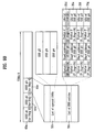
- FIG. 10B illustrates a process of recording the disc recording status (SRRI) as it pertains to the disc state as of FIG. 10A . Since the SRRI is a fourth recorded SRRI, the SRRI is named SRRI #4 (60d). The SRRI #4 (60d) is recorded next to the SRRI #3 (60c). For recording the status of the disc of
- the number of the SRR entries and the location of the opened SRRs are the same as those shown in FIG 9B , but since user data is recorded on a specific opened SRR, the LRA of the recorded opened SRR entry is changed and the value of the P_flag is also changed. In other words, information on the recorded SRRs #2 and #4 is updated. Since the SRR #2 is recorded with user data without padding, the P_flag of the SRR #2 entry 35i is maintained to be "0b”. Since the SRR #4 is recorded with user data and is padded, the P_flag of the SRR #4 entry 35k is changed to be "1b". In addition, since the status of the session #2 is not changed, the S_flags in the SRR entries 35h-35k are identical to those of the SRR entries in FIG. 9B .
- FIG. 11A shows Step 6 in which a session close command is received and executed when the disc is in the state of FIG. 10A .
- the session #2 that was an opened session is changed into a closed session #2 and all the SRRs of the session #2 are also closed into closed SRRs #2 - #4.
- the additionally recordable portion of the opened SRR is padded with dummy data and closed.
- the entire additionally recordable portion of the opened SRR may be padded with dummy data and closed. It is described above that this is an optional matter.
- specific data for example, "CLSD" as character code
- the SRRs #2, #3 and #4 that were previously opened SRRs are changed into a closed partially recorded SRR #2, a closed empty SRR #3 and a complete SRR #4, which in turn form the closed session #2.
- an additionally recordable area remains but is changed into a closed SRR by a close command.
- LRA recorded in the SRR entry means an end location where the user data are actually recorded. Dummy data portion does not affect the determination of the LRA location as described above.
- a remaining outermost SRR #5 is an invisible SRR #5, which in turn forms a new opened session #3.
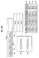
- the SRRI #5 (60e) is recorded next to the SRRI #5 (60d) in the TDMA0.
- the SRR number of the opened SRR (SRR #5) is recorded in the "List of opened SRRs" field 52e of the SRRI #5, and all the previous opened SRR numbers (for example, SRRs #2, #3 and #4 in FIG. 10B ) recorded in the SRRI #4 are removed from the current opened SRR list 52e. Removal of the SRRs from the "List of opened SRRs" field means that such SRRs are closed.
- Information on all five SRRs (SRRs #1 - #5) is recorded in the "List of SRR entries" field 30e of the SRRI #5 respectively as SRR entries 351-35p.
- the P_flags of the SRR #2 entry 35m and the SRR #3 entry 35n are changed to "1b" to indicate that at least a part of the corresponding SRR is padded with padding data. Since the LRA of an SRR entry is an end location where the user data is actually recorded, the LRAs of the SRRs #2 - #4 have the same value as the previous LRAs recorded in the SRRI #4 (60d). In addition, since user data is not yet recorded on the newly created invisible SRR #5, the P_flag of the SRR #5 entry 35p is set to be "0b". Since the SRR #5 is a start SRR of the new session #3, the S_flag of the SRR #5 entry 35p is set to be "1b".
- the SRRI is information representing the recording status of the current disc.
- the recording/playback apparatus checks the latest SRRI (in the above case, the SRRI #5) recorded finally in a management area and thereby knows exactly the current disc recording status including the location of a recordable area/SRR on the disc. Therefore, desired user data can be recorded in the recordable area of an opened session on the disc.
- FIG. 12 illustrates an optical disc recording/playback apparatus according to the present invention.
- This apparatus or other suitable apparatus or system can be used to implement the disc and/or SRRI structures and methods of the present invention discussed herein.
- the optical disc recording/playback apparatus includes a recording/playback unit 10 for recording and/or reproducing data to/from the optical disc and a controller 20 for controlling the recording/playback unit 10. All the elements of the recording/playback apparatus are operatively coupled.
- the controller 20 transmits a command for recording and/or reproducing to/from a special recording area such as an SRR/session on the disc, to the recording/playback unit 10.
- the recording/playback unit 10 records and/or reproduces data to/from the disc according to the commands of the controller 20.
- the recording/playback unit 10 includes an interface unit 12, a pick-up unit 11, a data processor 13, a servo unit 14, a memory 15 and a microcomputer 16.
- the interface unit 12 communicates with external devices such as the controller 20.
- the pick-up unit 11 records or reproduces data to/from the optical disc directly.
- the data processor 13 receives a reproduction signal from the pick-up unit 11, restores a preferred signal, modulates a signal proper to the optical disc, and transmits the signal.
- the servo unit 14 controls the pick-up unit 11 to read the signal from the optical disc or to record the signal to the optical disc.
- the memory 15 stores temporarily data and various information including management information as discussed herein.
- the microcomputer 16 controls the components of the recording/playback unit 10. Since the recording/playback apparatus shown in FIG. 12 can selectively perform a padding operation, a designer can more freely design the recording/ playback apparatus.
- the recording/ playback unit 10 can automatically store specific data during a padding operation.
- the method of recording and playing back data on an optical disc is classified into two kinds.
- the first one is the case of FIGs. 4A through 11B , which involves the method of completely recording data on an opened SRR, forcedly padding the remaining sector(s) in the cluster including the LRA, and recording information identifying whether or not padding has been performed to the remaining sector(s), or determining whether or not to pad the cluster and recording padding identification information according to the padding when closing an SRR.
- the second one is the method of closing all the SRRs in the session when the session is closed. No special buffer zone is provided between a session and the adjacent session.
- the start location (i.e., session start SRR) of the session is identified by the session identification information such as S_flag.
- the recording/ playback method of the optical disc will be described in detail.
- the optical disc such as a BD-WO
- the latest SRRI is read as the latest disc management information recorded in a TDMA.
- the SRRI header and the SRR entry(ies) recorded in the latest SRRI are read and temporarily stored in the memory 15 of the recording/playback unit 10.
- the stored SRRI represents the latest disc recording status.
- the opened SRR(s) can be identified through the SRRI header information. Through the SRR entry(ies), data can be recorded in the entire area of the disc or the existence and location of the non-recording status and opened session can be checked. Also, it can be identified whether or not the SRR has been padded with padding data. All such information can be used when the optical disc is recorded and played back.
- data e.g., user data
- data is recorded on a specific opened SRR.
- the unrecorded sector(s) in the cluster including the LRA is padded with dummy data (e.g., for stability and robust reasons) and the padding identification information Padding_flag is set to "1b".
- Padding_flag corresponding to each sector is set to "1b”. If the sector is not padded, then the corresponding Padding_flag is set to "0b”.
- the SRR status information P_flag is set to "1b" to indicate that the corresponding SRR has at least some part that is padded.
- the microcomputer 16 can select whether a recordable area (for example, one cluster) in the closed SRR is closed after padding or without padding.
- a designer can design so that the recording/playback unit 10 automatically pads the SRR with padding data and closes the SRR unconditionally without a padding command from the controller 20.
- the above function is called "automatic padding function" by the recording/playback unit 10.
- the automatic padding function is more advantageous to reduce padding operation time, compared to the case where the recording/ playback unit 10 receives dummy data by a padding command and pads the SRR thereafter.
- the Padding_flag is set to 1b according to each padded sector.
- the P_flag is set to 1b in the corresponding SRR entry. Different recording/playback apparatuses can use such information.
- the S_flag is set to 1b in the corresponding SRR entry to indicate the start location of the opened session.
- the types and definitions of the SRRs as defined by the present invention and a method of recording the SRRI according to the defined SRR types and definitions, are provided. Accordingly, various recording/ playback apparatuses having desired functions can be used to access the present disc.
- the method for recording management information of the write-once optical disc according to the present invention includes defining new SRR types and session types. If an open SRR is padded or if the SRR is closed by padding, padding identification information Padding_flag is set appropriately and recorded in the padded area. Other padding identification information P_flag and the session identification information S_flag are recorded in the SRR entry. Consequently, in the write-once optical disc having the new physical structure, the management information can be effectively recorded and managed.
Description
- The present invention relates to a write-once optical disc, a method for recording management information of the write-once optical disc and a method and apparatus for recording and playing back the write-once optical disc.
- As an optical recording medium, optical discs on which high-capacity data can be recorded are widely being used. Among them, a new high-density optical recording medium (HD-DVD), for example, a Blu-ray disc, has been recently developed for recording and storing high-definition video data and high-quality audio data for a long term period.
- The Blu-ray disc is the next generation HD-DVD technology and the next generation optical recording solution, and has an excellent capability to store data more than the existing DVDs. Recently, a technical specification of international standard for HD-DVD has been established. Related with this, various standards for a write-once Blu-ray disc (BD-WO) are being prepared following the standards for a rewritable Blu-ray disc (BD-RE). Among the standards for the write-once Blu-ray disc (BD-WO), a method for recording management information has been discussed. This method involves a recording method of an information indicating a recorded status of the disc, which is one of the characteristics of the write-once optical disc. The information indicating the recorded status of the disc allows a host or a user to easily find a recordable area on the write-once optical disc. In the existing write-once optical discs, this information is named variously. For example, in the case of CD series, this information is named a track information; in the case of DVD series, this information is named an RZone or a fragment.
-
WO-A-2005/006314 , which is an elder European patent application, discloses a write-once optical disk, and a method and apparatus for recording management information on the write-once optical disc, the optical disc including at least one recording layer, and at least one SRR entry, each SRR entry corresponding to an SRR and including at least one status field for indicating a recording status of the corresponding SRR. -
WO-A-2005/004154 , which is an elder European patent application, discloses a write-once recording medium comprising a management information area for recording management information for managing a recorded state, and a user data area for recording user data, wherein at least one session is configured to contain at least one of at least one recording area contained in the user data. - Accordingly, there is an increasing demand for a method of efficiently recording the management information corresponding to the recorded status of the high-density optical disc. And this method must be provided with the standardized information in order to secure mutual compatibility. In addition, there is a demand for a method of recording the management information on a disc, which can be applied to a write-once high-density optical disc performing defect management, as well as to the Blu-ray discs.
- Accordingly, the present invention is directed to an optical disc and a method and apparatus for recording disc management information as defined according to the claims, and particularly to a method and apparatus for efficiently managing the disc recording status information, which substantially obviate one or more problems due to limitations and disadvantages of the related art.
- An object of the present invention is to provide a write-once optical disc and a method and apparatus for defining types of sessions and sequential recording ranges (SRRs) for the disc.
- Another object of the present invention is to provide a method and apparatus for recording SRR information (SRRI) as a disc recording status information that can be applied to a write-once optical disc.
- Additional advantages, objects, and features of the invention will be set forth in part in the description which follows and in part will become apparent to those having ordinary skill in the art upon examination of the following or may be learned from practice of the invention. The objectives and other advantages of the invention may be realized and attained by the structure particularly pointed out in the written description and claims hereof as well as the appended drawings.
- It is to be understood that both the foregoing general description and the following detailed description of the present invention are exemplary and explanatory and are intended to provide further explanation of the invention as claimed.
- The accompanying drawings, which are included to provide a further understanding of the invention and are incorporated in and constitute a part of this application, illustrate embodiment(s) of the invention and together with the description serve to explain the principle of the invention. In the drawings:
-
FIG. 1 illustrates an overall structure of a write-once optical disc and a method for recording management information on the write-once optical disc according to the present invention; -
FIGs. 2A through 2D illustrate different types of opened SRRs of a write-once optical disc according to the present invention; -
FIGs. 3A through 3E illustrate different types of closed SRRs of a write-once optical disc according to the present invention; -
FIG. 4A illustrates an example of padding identification information when padding dummy data to a closed SRR of a write-once optical disc according to the present invention; -
FIG. 4B illustrates an example of padding identification information when padding dummy data to an opened SRR of a write-once optical disc according to the present invention; -
FIG. 4C illustrates an example of a session of a write-once optical disc according to the present invention; -
FIG. 5 illustrates an overall structure of a write-once optical disc and a method for recording SRRI as disc management information according to the present invention; -
FIG. 6A illustrates a structure of an SRR entry list recorded in an SRRI according to the present invention; -
FIG. 6B illustrates an example of an SRR entry recorded in the SRR entry list ofFIG. 6A according to the present invention; -
FIG. 6C illustrates an example of a structure of a list of opened SRRs field of an SRRI according to the present invention; -
FIGs. 7A through 11B illustrate a process of recording SRRI according to the disc recording status in a write-once optical disc according to the present invention; and -
FIG. 12 illustrates a recording/playback apparatus for a write-once optical disc according to an embodiment of the present invention. - Reference will now be made in detail to the preferred embodiments of the present invention, examples of which are illustrated in the accompanying drawings. Wherever possible, the same reference numbers will be used throughout the drawings to refer to the same or like parts.
- For the convenience of description, a write-once Blu-ray disc (BD-WO) is described for example. Most of the terminologies in this specification are widespread general words but there are some words selected and used by the inventor, the meaning of which will be described in detail in the corresponding description. The present invention should be understood not based on the simple meanings of the words but based on the specifically described meanings of the words, if such meanings have been discussed.
- In this specification, "SRR" (sequential recording range) means an area provided to record data on a disc and is a unit of recording for sequential recording (sequential recording-unit). An SRR has a size of one or more clusters. "SRR information" (SRRI) is a name for information identifying a recording status of a disc. SRRI is applied to a sequential recording mode of the disc and pertains to one or more SRRs. "Padding" means filling an unrecorded area in an SRR with dummy data or zeros at a user's request or under control of a recording/playback apparatus (
FIG. 12 ). "Session" is composed of one or more consecutive SRRs and identifies SRRs for compatibility to the specification only for playbacks. -
FIG. 1 illustrates a structure of a write-once optical disc such as a BD-WO and a method for recording disc management information according to the present invention. The disc shown inFIG. 1 has a single recording layer as an example. But the present invention is not limited to such, and is applicable to a disc having dual or multiple recording layers. - Referring to
FIG. 1 , the disc includes a lead-in area, a data area, and a lead-out area, all at the recording layer. The lead-in and lead-out areas have a plurality of disc (or defect) management areas (DMA1 - DMA4) for storing the same defect management information repeatedly. In the data area, an inner spare area ISAO and/or an outer spare area OSAO for replacing defective areas is provided. - It is known that a rewritable optical disc does not have or need a large DMA since its DMA can be written and erased repeatedly, even if the disc has the DMA of a limited size. This is not the case for a write-once optical disc such as a BD-WO. Since the write-once optical disc cannot be re-recorded on the area that was recorded once, the write-once optical disc needs and has a larger management area. To more effectively store management information, in the write-once optical disc the management information is temporarily stored in a temporary disc management area (TDMA). When the disc is ready to be finalized/closed, then the management information stored in a final/latest TDMA is transferred to a DMA for more permanent storage.
- As shown in
FIG. 1 , the disc includes two TDMAs: TDMA0 and TDMA1. The TDMA0 is allocated to the lead-in area and has a fixed, non-variable size. The TDMA1 is allocated to the outer spare area OSAO and has a size variable in accordance with the size of the spare area. The size P of the TDMA1 may be, for example, P = (N * 256) / 4 clusters where N is a positive integer, which is about one fourth of the size of the entire outer spare area OSAO. - In each of the TDMA0 and TDMA1, temporary defect list (TDFL) information and temporary disc definition structure (TDDS) information together (TDFL + TDDS) can be recorded in one recording-unit (e.g., one cluster in the case of a BD-WO), or SRRI and TDDS information together (SRRI + TDDS) can be recorded in one recording-unit as shown. The SRRI is recorded when a sequential recording mode is used, whereas SBM (space bit map) is used when a random recording mode is used.
- At each update time, (TDFL + TDDS) or (SRRI + TDDS) are recorded to the TDMA in the size of one cluster. In the example of
FIG. 1 , a TDFL and a TDDS are recorded in one cluster of the TDMA0, an SRRI and a TDDS are recorded in the next cluster of the TDMA0, an SRRI and a TDDS are recorded in the next cluster of the TDMA0, and so on. - If a defective area occurs within the data area, a process of replacing it with the spare area is carried out. The TDFL is the information that manages this process as the defect list. In the case of a single layer disc, the TDFL is recorded with the size of 1 cluster to 4 clusters according to the size of the defect list. SRRI is Information informing of whether a specific area of the disc is recorded or unrecorded. The SRRI can be widely used when the disc is of a consecutive recording type. That is, the SRRI can be usefully applied to the case where the disc is recorded in a sequential or incremental recording mode. In addition, the TDDS information is generally recorded on the last sector among the 32 sectors within one cluster of the management area. Information for general management and defect management of the disc is recorded as part of the TDDS information, and the TDDS information is generally always recorded last when the management information is updated within the TDMA.
- The present invention relates to a method of generating and recording disc recording status information, which is applied to a new high density optical disc such as a BD-WO. In the present invention, SRRI is used as the disc recording status information, and various types of SRRs are defined as shown in
FIGs. 2A through 3E . The detailed structure of SRRI will be described referring toFIGs. 5A through 6C . The present invention also defines and distinguishes different types of SRRs formed on the disc and uses them to record and playback the optical disc. A method of newly defining the types of the SRRs and creating information identifying the types of distinguished SRRs will be described in detail. -
FIGs. 2A to 2D illustrate different types of opened SRRs for the write-once optical disc (e.g., a BD-WO) according to the present invention. An opened SRR is an SRR in which data can be recorded. If the SRR is recordable, the SRR has "next writable address" (NWA). Accordingly, the opened SRR is the SRR having the NWA. The SRR that does not have the NWA and is not recordable is called a closed SRR. The closed SRR will be described referring toFIGs. 3A through 3E . - More specifically,
FIG. 2A shows an invisible SRR that is one type of an opened SRR. The invisible SRR is generally always formed on an outermost section of a disc or an initial black disc and means an unrecorded area. In other words, only a start address of the invisible SRR is defined and an end address of the invisible SRR means an end of user data. Since data is not yet recorded, "last recorded area" (LRA) has a zero value and the NWA has the same value as the start address of the invisible SRR. -
FIG. 2B shows an incomplete SRR that is another type of an opened SRR. The incomplete SRR is an SRR that is partially recorded in the invisible SRR ofFIG. 2A . In other words, only a start address of the incomplete SRR is defined and an end address of the incomplete SRR means an end of user data. However, since data is partially recorded in the incomplete SRR, the LRA of the incomplete SRR represents the last address at which normal user data is recorded and the NWA is the next writable address from the LRA of the incomplete SRR. That is, the NWA is the first physical sector number (PSN) of the next available unrecorded cluster in the related SRR. - In the opened SRR, if the SRR is partially recorded, the relation between the LRA and the NWA will be now described in detail in relation with padding shown in
FIG. 2B . The enlarged view of the small dotted box portion inFIG. 2B is provided at a lower portion of the drawing. - In other words, LRA means the area in which user data are actually recorded. If the user data are recorded on some sectors in one cluster consisting of thirty-two sectors, the PSN of a last sector on which the user data are recorded is the LRA as shown in
FIG. 2B . However, since the basic recording-unit of the Blu-ray disc is a cluster, NWA representing an additionally recordable area will be the PSN of a header sector of the following cluster. Accordingly, if data is recorded on some sectors of the cluster and recording is finished (i.e., the sequential recording is terminated), the remaining unrecorded sectors are padded with dummy data according to the present invention. For instance, the remaining unrecorded sectors of the cluster are padded with zeros as shown. If all the user data are recorded on even the last sector of the cluster, it is obvious that the padding described is not necessary. -
FIG. 2C shows an empty SRR that is yet another type of an opened SRR. The empty SRR is formed generally not at an outermost section of the disc, but is formed generally at a middle section to record data in contrast to the invisible SRR and the incomplete SRR ofFIGs. 2A and2B . In other words, it is the case where a host or user makes an SRR, but does not yet record data on the SRR. Since the empty SRR has a start address and an end address but is not yet recorded, the LRA of the empty SRR has a "zero" value and the NWA has the same value as the start address of the empty SRR. -
FIG. 2D shows a partially recorded SRR that is yet another type of an opened SRR. The partially recorded SRR is an SRR that is partially recorded in the empty SRR ofFIG. 2C . Accordingly, the partially recorded SRR has a start address and an end address. Since data is partially recorded in the partially recorded SRR, the LRA of the partially recorded SRR represents the last address at which normal data is recorded and the NWA is the next writable address from the LRA. - In the opened SRR of
FIG. 2D , if the SRR is partially recorded, the enlarged view of the small dotted portion inFIG. 2D shows the relation between the LRA and NWA in relation with padding. The detailed description on this feature is omitted since it is the same as the description ofFIG. 2B . - Accordingly, referring to
FIGs. 2A through 2D , the opened SRRs of the present invention are classified into the unrecorded opened SRRs (FIGs. 2A and2C ) and the partially recorded opened SRRs (FIGs. 2B and2D ). The partially recorded opened SRRs (FIGs. 2B and2D ) can be classified into an opened SRR padded after the LRA, and an unpadded opened SRR. - According to the present invention, the total number of opened SRRs at any given time is limited to a predetermined number in the write-once optical disc due to a difficulty in management if the number of opened SRRs is large. For example, the total number of the opened SRRs on the disc may be sixteen at most in the BD-WO of the present invention. The information on the location and the number of the opened SRRs can be referred to using a "list of opened SRRs" field and a "number of opened SRRs" field in a header of the SRRI. The "list of opened SRRs" field and the "number of opened SRRs" field in the SRRI header will be described later when the SRRI structure is discussed referring to
FIGs. 5 through 6C . -
FIGs. 3A to 3E illustrate different types of closed SRRs for a write-once optical disc such as a BD-WO according to the present invention. A closed SRR is an SRR in which data (e.g., user data) cannot be recorded. If the SRR is not recordable, the SRR does not have a NWA. The closed SRR may be created because the SRR is fully recorded. Also, the closed SRR may be created because a user or host closes the SRR by a close command even though a recordable area remains in the SRR. - Particularly,
FIG. 3A shows an empty SRR that is one type of a closed SRR. The empty SRR is an opened empty SRR (FIG. 2C ) that is closed by a close command without any user-data recording thereto. Accordingly,FIG. 3A shows a closed empty SRR andFIG. 2C shows an opened empty SRR. -
FIG. 3B shows a partially recorded SRR that is another type of a closed SRR. The partially recorded SRR ofFIG. 3B is the opened partially recorded SRR ofFIG. 2D that is closed by a close command without any additional user-data recording thereto. Accordingly,FIG. 3B shows a closed partially recorded SRR andFIG. 2D shows an opened partially recorded SRR. -
FIG. 3C shows a complete SRR that is yet another type of a closed SRR. The complete SRR is an SRR in which user data are recorded fully in the SRR, or which is padded fully with dummy data. The complete SRR exists only among the closed SRRs. -
FIG. 3D shows a closed partially recorded SRR that is yet another type of a closed SRR. The partially recorded SRR ofFIG. 3D is an SRR that is padded with dummy data in a recordable area after its LRA when closing the opened partially recorded SRR ofFIG. 2D . Herein, all the recordable areas or only some recordable areas (for example, one or more clusters) of the SRR after its LRA or NWA may be padded with dummy data used as padding data. In addition, when some areas are padded, a specific character code such as ASCII characters may be recorded as the padding data, instead of recording the dummy data so as to represent that the SRR is closed. In this case, the specific character code to be used as the padding data can be characters such as "CLSD" representing that a corresponding SRR is closed. -
FIG. 3E shows an empty SRR that is another type of a closed SRR. The empty SRR ofFIG. 3E is an SRR that is padded with specific dummy data in a recordable area after its LRA and then closed when closing the opened empty SRR ofFIG. 2C . Herein, all the recordable areas or only some recordable areas (for example, one or more clusters) of the SRR after its LRA or NWA may be padded with dummy data used as padding data. In addition, when some areas are padded, a specific character code such as ASCII characters may be recorded as the padding data, instead of recording the dummy data so as to represent that the SRR is closed. In this case, the specific character code to be used as the padding data can be characters such as "CLSD" representing that a corresponding SRR is closed. - If the closed SRRs of
FIGs. 3D and 3E are fully padded with dummy data up to the end address, the closed SRRs ofFIGs. 3D and 3E are the same SRRs as the complete SRR described above referring toFIG. 3C . In other words, in the present invention, in determining the type of the closed SRR, the closed SRRs are defined to distinguish the case of closing the unrecorded remaining area(s) of the SRR without padding (FIGs. 3A and 3B ) from the case of padding and closing the unrecorded remaining area(s) of the SRR (FIGs. 3D and 3E ) when the opened SRR is changed into the closed SRR by a close command. - Additionally, in the present invention, when closing an SRR, it is possible to close the SRR without padding or to close the SRR after padding with specific padding data. It is considered that the Blu-ray disc is compatible to a disc only for playback in the same family though SRRs or if unrecorded areas are padded. A recording/playback apparatus (e.g., as shown in
FIG. 12 ) can selectively pad the disc so that the freedom of the design of the recording/ playback apparatus is further ensured. When padding the disc, a recording/playback part (e.g., thecomponent 10 inFIG. 12 ) of the recording/playback apparatus can automatically record specific data, so that thecomponent 10 receives specific data from acontroller 20 and can solve the time problem in the case of padding. -
FIGs. 4A and 4B illustrate examples of padding identification information when padding dummy data respectively to a closed SRR and an opened SRR of a write-once optical disc according to an embodiment of the present invention. The padding may be performed to an opened SRR when closing the opened SRR. But it can also be performed to an opened SRR in response to a command not necessarily to close the SRR (e.g., in the cases ofFIGs. 2B and2D ). That is,FIG. 4A is related toFIG. 2B or2D , andFIG. 4B is related toFIG. 3D or 3E . - More specifically,
FIG. 4A shows a case where the actual user data is recorded on only some areas of one cluster and the remaining areas of the cluster are padded with dummy data in the case of an opened SRR.FIG. 4A shows that padding identification information "Padding_flag" for distinguishing a sector in which actual user data is recorded from a sector padded with dummy data is set as control data in the corresponding cluster. There exist 32 Padding_flags each corresponding to one of the 32 sectors of the cluster. - As shown in
FIG. 4A , in this example, since sector 0 -sector 29 are the areas in which user data are recorded, the Padding_flag for each of these sectors is set to a certain value, e.g., "0b," so as to indicate that no padding is present to the corresponding sector. On the other hand, sincesector 30 andsector 31 are the areas padded with padding data, the Padding_flag for each of these sectors is set to a value such as "1b" so as to indicate that padding is present in the corresponding sectors. - In this example, the LRA represents the location (first PSN) of
sector 29. Accordingly, the optical recording/playback apparatus can decode a cluster including the LRA, read the Padding_flag corresponding to each of the sectors and then distinguish accurately a sector on which user data is recorded from a sector padded with dummy data in the cluster. -
FIG. 4B shows that a specific cluster of the recordable areas in an SRR is fully padded with dummy data in the case of closing the SRR.FIG. 4B shows that padding identification information "Padding_flag" for distinguishing an SRR closed without padding from an SRR closed after padding is set as control flag in the corresponding cluster. - As shown in
FIG. 4B , in this example, since sector 0 -sector 31 are the areas padded fully with dummy data, the Padding_flag is set to a certain value such as "1b" for all the sectors. Consequently, the optical recording/playback apparatus can decode a cluster having the padding identification information (Padding_flag) as described above, read the Padding_flag corresponding to each of the sectors and then accurately recognize that all sectors in the cluster are padded with dummy data. - In other words,
FIG. 4A relates to padding for terminating the sequential recording on the disc whereasFIG. 4B relates to padding for closing an SRR.FIG. 4A shows that all the remaining sectors in the related cluster are padded with dummy data when the sequential recording is terminated. Each padding flag corresponds to each sector of the cluster, and is set to "1b" if the corresponding sector is padded. In the case ofFIG. 4A , padding occurs one sector at a time. On the other hand, in the case ofFIG. 4B , one or more clusters (one cluster at a time) are padded when closing the SRR. For one cluster padding, 32 padding flags corresponding to 32 sectors of that cluster are all set to "1b" to indicate the padding of that cluster as shown inFIG. 4B . -
FIG. 4C illustrates an example of a session of the write-once optical disc according to an embodiment of the present invention. A "session" is an upper-level recording-unit compared to the lower-level recording-unit such as an SRR, and includes at least one SRR. A plurality of sessions can be recorded on the disc and such a disc is called a multi-session disc. Referring toFIG. 4C , the concept of the session of the present invention will be now described. - First, a plurality of sessions of the present invention can be allocated from the inner track of the disc toward the outer track direction of the disc, and the session numbers are given sequentially to such sessions. Even if a plurality of sessions exist, there may be only one opened session on the disc at a given time. This opened session is the session whose session number is the highest among the existing sessions. In other words, the session formed on the outermost track at a given time is a recordable session and is called the opened session. When the recording is finished or a close command is received, then the currently opened session is closed into a closed session. All the SRRs in the closed session should be closed also into closed SRRs. Herein, if the session to be closed includes an invisible SRR, the corresponding invisible SRR is excluded from being closed and only the remaining SRR is closed. The excluded invisible SRR is then formed as a new open session. In
FIG. 4C , asession # 1 represents a closed session and asession # 2 represents an opened session as an example. Thesession # 1 is composed of anSRR # 1 and anSRR # 2, whereas thesession # 2 is composed of anSRR # 3, anSRR # 4, anSRR # 5, etc. - When the session is closed and also the SRR is closed, the SRR can be closed after padding or without padding as described above. Identification on whether the padding is present is identified by "Padding_flag". When an incomplete SRR is closed, only a recoded area of the SRR is closed and an unrecorded area of the SRR is changed into an invisible SRR forming a new opened session.
- There is no special buffer zone between a session and another adjacent session. Instead, a "session start bit" in the SRRI is provided to indicate whether or not the corresponding SRR is the start of the session. The session start bit will be described later in detail when the SRRI structure is described. Additionally, although a plurality of SRRs can exist in the opened session (the
session # 2 ofFIG. 4C , for example), all the SRRs of that session do not have to be opened SRRs and it is sufficient that at least one opened SRR exists in the opened session. InFIG. 4C , theSRRs # 3 and #5 in the openedsession # 2 are opened SRRs and theSRR # 4 is a closed SRR.FIGs. 5 through 6C illustrate a structure of SRRI and information included in the SRRI according to the present invention. - Particularly,
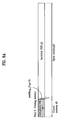
FIG. 5 illustrates the overall structure of an SRRI. The SRRI pertains to one or more SRRs and is management information providing disc recording status. The SRRIs are recorded in TDMA(s) (e.g., the TDMAO) in the optical disc structure ofFIGs. 1 and5 . As shown inFIG. 5 , each SRRI 60 in a TDMA is composed of three parts: aheader 50, a list ofSRR entries 30 and anSRR list terminator 40. Theheader 50 identifies the SRRI. The list ofSRR entries 30 represents the recording status of each of the corresponding SRRs. TheSRR list terminator 40 represents an end or termination of the SRRI. - The
header 50 is located at a header in the SRRI and includes an "SRRI structure identifier"field 51, a "List of opened SRRs"field 52, a "Number of SRR entries"field 53 and a "Number of opened SRRs"field 54, so that the overall SRR entry contents can be checked before the SRR entry list is read. Herein, the "SRRI structure identifier"field 51 identifies the SRRI. The "List of opened SRRs"field 52 informs of the location (identification) of the opened SRRs associated with the corresponding SRRI and will be described later in more detail referring toFIG. 6C . The "Number of SRR entries"field 53 represents the total number of all SRRs associated with theSRRI 60. The "Number of opened SRRs"field 54 represents the total number of opened SRRs. - After the
header 50, the list of SRR entries (or the SRR entry list) 30 is recorded in the SRRI. After the last SRR entry, the end of the SRRI is marked with theSRR list terminator 40. TheSRR list terminator 40 is meaningful as information indicating an end location of the corresponding SRRI if the SRRI has a variable size. - Accordingly, as disc management information, the SRRI is composed of the
header 50, theSRR entry list 30 and theSRR list terminator 40. All such information is recorded in batch whenever it is updated. -
FIG. 6A illustrates an example of theSRR entry list 30 recorded in an SRRI according to the present invention. As shown inFIG. 6A , theSRR entry list 30 is composed of one ormore SRR entries 35. Each of theSRR entries 35 carries information on one SRR (identified by the SRR number) on the disc, has a size of eight bytes (64 bits) and represents the recording status of the corresponding SRR. EachSRR entry 35 includes a status field 31 (Status 1) for storing the status of the corresponding SRR, astart address field 32 for storing a start address of the corresponding SRR, another status field 33 (Status 2) for storing the status of the corresponding SRR, and a last recorded address (LRA)field 34 for storing the LRA of the corresponding SRR (i.e., the end address of the user data stored in the SRR). Generally, the start address of the corresponding SRR in thestart address field 32 is represented as a physical sector number (PSN). - According to an embodiment, the first 4 most significant bits (b63-b60) among the 64 bits of the
SRR entry 35 are allocated to thefirst status field 31, the next 28 bits (b59-b32) of theSRR entry 35 are allocated to thestart address field 32, the next 4 bits (b31-b28) of theSRR entry 35 are allocated to thesecond status field 33, and the last 28 bits (b27-b0) of theSRR entry 35 are allocated to theLRA field 34. -
FIG. 6B illustrates an example of theSRR entry 35 recorded in theSRR entry list 30 according to the present invention. TheStatus 1field 31 is used to store information identifying whether or not any padding is performed in the corresponding SRR. TheStatus 2field 33 is used to store information identifying whether or not the corresponding SRR is the start of a session. - As shown in
FIG. 6B , out of the 4 heading bits allocated to theStatus 1field 31, one bit is used to store a padding identification information "P_flag" identifying whether or not the padding is present. The other three bits of the 4 heading bits are reserved for any change of regulation. - It should be noted that the padding identification information "P_flag" recorded in the SRR entry is similar to the padding identification information "Padding_flag" described referring to
FIGs. 4A and 4B . However, they have different objects. If a specific SRR is finally padded, the P_flag is recorded in the SRR entry to directly represent that the corresponding SRR is a padded SRR. Accordingly, the optical recording/playback apparatus (FIG. 12 ) can easily check whether or not the corresponding SRR is padded by examining the P_flag recorded as management information in the SRR entry. After that, the optical recording/playback apparatus decodes the corresponding cluster (SRR) described above referring toFIGs. 4A and 4B and reads from the cluster the value of the Padding_flag corresponding to each sector of the SRR, so that the optical recording/ playback apparatus is able to determine how much of the SRR is padded after its LRA. - In the example of
FIG. 6B , the first bit (31a) of theStatus 1field 31 carries the P-flag and the remaining 3 bits (31b) of thefield 31 are reserved. If P_flag = 1b, it means that the corresponding SRR is a padded SRR (i.e., the SRR has at least some portion that is padded with padding data). If P_flag = 0b, it means that the corresponding SRR is an unpadded SRR. - The
Status 2field 33, which is allocated with 4 bits, carries information on whether or not the corresponding SRR is the session start SRR. One bit of the four-bit field 33 carries a session identification information "S_flag" identifying whether or not the corresponding SRR is a start SRR of a session. The other three bits of thefield 33 are reserved for any change of regulation. In other words, the S_flag is the above-mentioned "session start bit". In the example, the first bit (33a) of the four-bit field 33 stores the S-flag and the remaining 3 bits (33b) are reserved. If S_flag = 1b, it means that the corresponding SRR is a start SRR of a session. If S_flag = 0b, it means that the corresponding SRR is not a start SRR of a session. - One reason for identifying a start of a session through the S_flag is to provide compatibility with existing disc structures such as DVDs that allocate additional area (for example, border-in/border-out) to distinguish sessions. However, allocation of the additional area reduces the entire recording capacity of the disc. As such, the present invention overcomes this limitation by providing the session identification information (S_flag) in the
SRR entry 35. Accordingly, the session structure of the entire disc can be easily recognized using the session identification information S_flag in theSRR entry 35 without having to allocate additional areas to store such session distinguishing information. - For the convenience of description of the present invention, the P_flag and the S_flag are depicted as separate status information stored in separate status fields of an SRR entry, but they can be stored together in one status field of the SRR entry.
- The
LRA field 34 of theSRR entry 35 is a field for recording an end address (LRA) of user data recorded in the corresponding SRR and stores an end address of the user data (excluding any padding data) recorded in the corresponding SRR -
FIG. 6C illustrates a detailed structure of the "List of opened SRRs"field 52 of the SRRI inFIG. 5 according to an embodiment of the present invention. The information stored in thefield 52 is used to determine the location/identification of each opened SRR. As shown inFIG. 6C , one or more opened SRR numbers are recoded in the "List of opened SRRs"field 52 as location information of the opened SRRs. Two bytes are allocated to record an opened SRR number identifying a particular SRR. - In the present invention, if there are at most sixteen opened SRRs on the disc, the location (identification) of the corresponding opened SRRs (and thus the opened SRR entries) is recorded through each opened SRR number. Accordingly, when loading an optical disc having the disc structure of the present invention, the recording/playback apparatus can determine the location of recordable areas (NWA) of the disc based on the opened SRR information of the present invention. In other words, the location of the opened SRR on the current disc should be known to record data. Since the information identifying whether a corresponding SRR is an opened SRR or a closed SRR is not provided specifically in the SRR entry, the identification/location of the opened SRR is recorded in the header of the SRRI and can be accessed easily, so that the optical recording/playback apparatus is able to easily read the SRR entry associated with the identified opened SRR.
- Accordingly, only the SRR having the SRR number recorded on the "List of opened SRRs"
field 52 is additionally recordable as an opened SRR. After that, if the SRR is changed into a closed SRR, the SRR number of the closed SRR is removed from the "List of opened SRRs"field 52 so that it is possible to easily distinguish the opened SRR from the closed SRR. - A method for updating the SRRI representing the disc recording status according to the present invention will be now described. Particularly, a method of opening and closing SRRs and sessions, padding an SRR with dummy data and recording SRRIs will be described referring to
FIGS. 7A-11B . -
FIGs. 7A through 11B illustrate sequentially a method of recording SRRI according to the disc recording status in the write-once optical disc of the present invention. More specifically,FIGs. 7A through 11B show sequentially how the different types of SRRs (shown inFIGs. 2A through 3E ) on the disc are created and how to record the SRRI using the sequential steps performed according a time flow. These methods are implemented on the write-once optical disc such as BD-WO having the SRR, the SRRI and the disc structure as discussed herein in connection withFIGs. 1-6C . -
FIG. 7A showsStep 1 in which the entire area of the disc is recordable as an initial blank disc and a portion designated by a thick arrow indicates the NWA location. The start location of the disc is the NWA. Herein, only one SRR (SRR # 1) exists on the disc. This is the invisible SRR shown inFIG. 2A . Accordingly, a session is in the initial state of the disc wherein only one openedsession # 1 exists. The disc is a blank disc and the SRRI is not yet recorded on the disc. -
FIG. 7B showsStep 2 in which data (e.g., user data) are partially recorded on the blank disc ofFIG. 7A , but thesession # 1 is not yet closed. Herein, only one SRR (SRR #1) exists on the disc, which is the incomplete SRR shown inFIG. 2B . Thesession # 1 is maintained as the opened session. As shown inFIG. 7B , the user data is recorded in a portion of theincomplete SRR # 1 and an unrecorded portion (e.g., sector(s)) of the SRR # 1 (cluster) is padded with dummy data. As described above, the padded sector of the SRR is indicated with "Padding_flag = 1b" which is recorded in a designated area of the cluster, e.g., within the padded sector of the cluster/SRR # 1. -
FIG. 7C illustrates a process of recording an SRRI in the management area of the disc when the disc is in the state ofFIG. 7B . For the convenience of explanation, only certain portions among all the different components of the disc structure and SRRI structure shown inFIGs. 1 and5 are shown. For instance, although the (SRRI + TDDS) or (TDFL + TDDS) are recorded in each cluster of the TDMA such as the TDMA0 of the disc as discussed above, only the SRRI is shown in the TDMA0 ofFIG. 7C , and the TDFL and/or TDDS is omitted for the sake of clarity. Further, only the "List of opened SRRs"field 52 and the "List of SRR entries"field 30 among the different fields of the SRRI shown inFIG. 5 are shown. - The disc recording status of
FIG. 7C is the case where only one opened SRR (SRR #1) is present in all the disc area as inFIG. 7B . As shown inFIG. 7C , when theincomplete SRR # 1 is formed without closing the session as inFIG. 7B , the SRRI #1 (60a) pertaining to theSRR # 1 is generated and recorded in the TDMA0. In the SRRI #1 (60a), the SRR number (SRR #1) of the openedSRR # 1 is recorded in its "List of opened SRRs"field 52a. In the "List of SRR entries"field 30a of the SRRI #1 (60a), only oneSRR entry 35a pertaining to theSRR # 1 is present. TheSRR entry 35a (orSRR entries 35b-35p discussed later) has the SRR entry structure ofFIGs. 6A and 6B discussed above. - In the
SRR entry 35a, since some portions of theSRR # 1 are padded finally, the P_flag is set to "1b" as the status information of thecorresponding SRR # 1. Since theSRR # 1 is the start SRR of the openedsession # 1, the S_flag is set to "1b" as the status information of thecorresponding SRR # 1. -
FIG. 8A showsStep 3 in which a session close command is received and executed atStep 2 ofFIG. 7B . In response to the session close command, the area on which user data is recorded is separated into an independent closed SRR and a new session is created at the area following the user data recorded area. For instance, as shown inFIG. 8A , the portion of the area that is recorded fully with the user data atStep 2 becomes the complete SRR # 1 (closed SRR) which in turn forms theclosed session # 1. In addition, the unrecorded area becomes an invisible SRR #2 (opened SRR) which in turn forms an openedsession # 2 at the same time. -
FIG. 8B illustrates a process of recording the disc recording status (SRRI) as it pertains to the disc state as ofFIG. 8A . Since the SRRI is a second recorded SRRI, this SRRI is named SRRI #2 (60b). The SRRI #2 (60b) is recorded next to the SRRI #1 (60a) in the TDMA0. For recording the status of the disc ofFIG. 8A , since the entire area of the disc has only one opened SRR (SRR #2) and only one closed SRR (SRR #1), the SRR number of the openedSRR # 2 is recorded in the "List of opened SRRs"field 52b of theSRRI # 2, and information on theSRRs # 1 and #2 is recorded in the "List of SRR entries"field 30b of theSRRI # 2 respectively asSRR entries - The SRR entry (e.g., 35b) shadowed in
FIG. 8B (and in other figures) indicates that it is a closed SRR entry. Accordingly, since user data is not yet recorded in the newly createdSRR # 2, the P_flag of theSRR # 2 entry (35c) is set to "0b". Since theSRR # 2 is the start SRR of the openedsession # 2, the S_flag of theSRR # 2 entry (35c) is set to "1b". -
FIG. 9A showsStep 4 in which two opened SRRs are additionally reserved in the openedsession # 2 to newly record data when the disc is in the state of -
FIG. 8A . Accordingly, the newly created opened SRRs are openedempty SRRs # 2 and #3 and have NWAs indicated by thick arrows. As a result, the openedsession # 2 is composed of theempty SRRs # 2 and #3 and aninvisible SRR # 4. -
FIG. 9B illustrates a process of recording the disc recording status (SRRI) as it pertains to the disc state as ofFIG. 9A . Since the SRRI is a third recorded SRRI, the SRRI is named SRRI #3 (60c). The SRRI #3 (60c) is recorded adjacent to the SRRI #2 (60b) in the TDMA0. For recording the status of the disc ofFIG. 9A , since the entire area of the disc has three opened SRRs (SRRs # 2, #3 and #4) and one closed SRR (SRR #1), the SRR numbers (SRRs # 2, #3 and #4) of the opened SRRs are recorded in the "List of opened SRRs"field 52c of theSRRI # 3. Information on all four SRRs (SRRs #1 - #4) is recorded in the "List of SRR entries"field 30c of theSRRI # 3 respectively asSRR entries 35d-35g. - Accordingly, since information on the newly created
SRR # 2, #3 and #4 is recorded in the SRRI #3 (60c) and user data is not yet recorded on theSRRs # 2, #3 and #4, the P_flags of thecorresponding SRR entries SRRs # 3 and #4 are not the start SRR of the openedsession # 2, but theSRR # 2 is the session start SRR, the S_flags of theSRR # 2entry 35e, theSRR # 3entry 35f and theSRR # 4entry 35g are set respectively to "1b", "0b" and "0b". -
FIG. 10A showsStep 5 in which user data is recorded in theempty SRR # 2 and in theinvisible SRR # 4 ofFIG. 9A . Accordingly, the firstempty SRR # 2 is changed into a partially recordedSRR # 2, and theinvisible SRR # 4 is changed into anincomplete SRR # 4, but the second openedempty SRR # 3 is not changed. TheSRR # 2 is recorded with user data without padding. TheSRR # 4 is recorded with user data and is also padded with padding data. In the padded sector of theSRR # 4, the Padding_flag is set to "1b". -
FIG. 10B illustrates a process of recording the disc recording status (SRRI) as it pertains to the disc state as ofFIG. 10A . Since the SRRI is a fourth recorded SRRI, the SRRI is named SRRI #4 (60d). The SRRI #4 (60d) is recorded next to the SRRI #3 (60c). For recording the status of the disc of -
FIG. 10A , since the entire area of the disc has three opened SRRs (SRRs #2 - #4) and one closed SRR (SRR #1), the SRR numbers of the opened SRRs (SRRs #2 - #4) are recorded in the "List of opened SRRs"field 52d of the SRRI #4 (60d). Information on all four SRRs (SRRs #1 - #4) is recorded in the "List of SRR entries"field 30d of the SRRI #4 (60d) respectively asSRR entries 35h-35k. - At this step, the number of the SRR entries and the location of the opened SRRs are the same as those shown in
FIG 9B , but since user data is recorded on a specific opened SRR, the LRA of the recorded opened SRR entry is changed and the value of the P_flag is also changed. In other words, information on the recordedSRRs # 2 and #4 is updated. Since theSRR # 2 is recorded with user data without padding, the P_flag of theSRR # 2entry 35i is maintained to be "0b". Since theSRR # 4 is recorded with user data and is padded, the P_flag of theSRR # 4entry 35k is changed to be "1b". In addition, since the status of thesession # 2 is not changed, the S_flags in theSRR entries 35h-35k are identical to those of the SRR entries inFIG. 9B . -
FIG. 11A showsStep 6 in which a session close command is received and executed when the disc is in the state ofFIG. 10A . As a result, as shown inFIG. 11A , thesession # 2 that was an opened session is changed into aclosed session # 2 and all the SRRs of thesession # 2 are also closed into closed SRRs #2 - #4. Especially, the additionally recordable portion of the opened SRR is padded with dummy data and closed. The entire additionally recordable portion of the opened SRR may be padded with dummy data and closed. It is described above that this is an optional matter. In addition, when the padding is performed, specific data (for example, "CLSD" as character code) may be recordable as the padding data as described above. - The
SRRs # 2, #3 and #4 that were previously opened SRRs are changed into a closed partially recordedSRR # 2, a closedempty SRR # 3 and acomplete SRR # 4, which in turn form theclosed session # 2. In theSRRs # 2 and #3, an additionally recordable area remains but is changed into a closed SRR by a close command. Herein, some portion is alternatively padded with dummy data. Accordingly, all the sectors in the cluster/SRR (e.g.FIG. 4B ) padded with dummy data are set with Padding_flag = 1b. However, even in this case, LRA recorded in the SRR entry means an end location where the user data are actually recorded. Dummy data portion does not affect the determination of the LRA location as described above. A remainingoutermost SRR # 5 is aninvisible SRR # 5, which in turn forms a new openedsession # 3. -
FIG. 11B illustrates a process of recording the disc recording status (SRRI) as it pertains to the disc state as ofFIG. 11A . Since the SRRI is a fifth recorded SRRI in the management area, the SRRI is named SRRI #5 (60e). - The SRRI #5 (60e) is recorded next to the SRRI #5 (60d) in the TDMA0. For recording the status of the disc of
FIG. 11A , since the entire area of the disc has one opened SRR (SRR #5) and four closed SRRs (SRRs #1 - #4), the SRR number of the opened SRR (SRR #5) is recorded in the "List of opened SRRs" field 52e of theSRRI # 5, and all the previous opened SRR numbers (for example,SRRs # 2, #3 and #4 inFIG. 10B ) recorded in theSRRI # 4 are removed from the current opened SRR list 52e. Removal of the SRRs from the "List of opened SRRs" field means that such SRRs are closed. Information on all five SRRs (SRRs #1 - #5) is recorded in the "List of SRR entries" field 30e of theSRRI # 5 respectively as SRR entries 351-35p. - Since the
SRRs # 2 and #3 are padded with dummy data in response to the close command, the P_flags of theSRR # 2 entry 35m and theSRR # 3entry 35n are changed to "1b" to indicate that at least a part of the corresponding SRR is padded with padding data. Since the LRA of an SRR entry is an end location where the user data is actually recorded, the LRAs of the SRRs #2 - #4 have the same value as the previous LRAs recorded in the SRRI #4 (60d). In addition, since user data is not yet recorded on the newly createdinvisible SRR # 5, the P_flag of theSRR # 5entry 35p is set to be "0b". Since theSRR # 5 is a start SRR of thenew session # 3, the S_flag of theSRR # 5entry 35p is set to be "1b". - As known from
FIGs. 7A through 11B , the SRRI is information representing the recording status of the current disc. When the disc is loaded in the recording/playback apparatus, the recording/playback apparatus checks the latest SRRI (in the above case, the SRRI #5) recorded finally in a management area and thereby knows exactly the current disc recording status including the location of a recordable area/SRR on the disc. Therefore, desired user data can be recorded in the recordable area of an opened session on the disc. -
FIG. 12 illustrates an optical disc recording/playback apparatus according to the present invention. This apparatus or other suitable apparatus or system can be used to implement the disc and/or SRRI structures and methods of the present invention discussed herein. - Referring to
FIG. 12 , the optical disc recording/playback apparatus includes a recording/playback unit 10 for recording and/or reproducing data to/from the optical disc and acontroller 20 for controlling the recording/playback unit 10. All the elements of the recording/playback apparatus are operatively coupled. Thecontroller 20 transmits a command for recording and/or reproducing to/from a special recording area such as an SRR/session on the disc, to the recording/playback unit 10. The recording/playback unit 10 records and/or reproduces data to/from the disc according to the commands of thecontroller 20. - The recording/
playback unit 10 includes aninterface unit 12, a pick-upunit 11, adata processor 13, aservo unit 14, amemory 15 and amicrocomputer 16. Theinterface unit 12 communicates with external devices such as thecontroller 20. The pick-upunit 11 records or reproduces data to/from the optical disc directly. Thedata processor 13 receives a reproduction signal from the pick-upunit 11, restores a preferred signal, modulates a signal proper to the optical disc, and transmits the signal. Theservo unit 14 controls the pick-upunit 11 to read the signal from the optical disc or to record the signal to the optical disc. Thememory 15 stores temporarily data and various information including management information as discussed herein. Themicrocomputer 16 controls the components of the recording/playback unit 10. Since the recording/playback apparatus shown inFIG. 12 can selectively perform a padding operation, a designer can more freely design the recording/ playback apparatus. The recording/playback unit 10 can automatically store specific data during a padding operation. - The method of recording and playing back data on an optical disc is classified into two kinds. The first one is the case of
FIGs. 4A through 11B , which involves the method of completely recording data on an opened SRR, forcedly padding the remaining sector(s) in the cluster including the LRA, and recording information identifying whether or not padding has been performed to the remaining sector(s), or determining whether or not to pad the cluster and recording padding identification information according to the padding when closing an SRR. - The second one is the method of closing all the SRRs in the session when the session is closed. No special buffer zone is provided between a session and the adjacent session. The start location (i.e., session start SRR) of the session is identified by the session identification information such as S_flag.
- The recording/ playback method of the optical disc according to an embodiment of the present invention will be described in detail. When the optical disc such as a BD-WO is loaded into the recording/playback apparatus such as the one shown in
FIG. 12 , the latest SRRI is read as the latest disc management information recorded in a TDMA. Furthermore, the SRRI header and the SRR entry(ies) recorded in the latest SRRI are read and temporarily stored in thememory 15 of the recording/playback unit 10. - The stored SRRI represents the latest disc recording status. The opened SRR(s) can be identified through the SRRI header information. Through the SRR entry(ies), data can be recorded in the entire area of the disc or the existence and location of the non-recording status and opened session can be checked. Also, it can be identified whether or not the SRR has been padded with padding data. All such information can be used when the optical disc is recorded and played back.
- Then, data (e.g., user data) is recorded on a specific opened SRR. When the data is completely recorded in the opened SRR, the unrecorded sector(s) in the cluster including the LRA is padded with dummy data (e.g., for stability and robust reasons) and the padding identification information Padding_flag is set to "1b". For each of the padded sectors, Padding_flag corresponding to each sector is set to "1b". If the sector is not padded, then the corresponding Padding_flag is set to "0b". Also, when the SRR entry in the SRRI is updated, the SRR status information P_flag is set to "1b" to indicate that the corresponding SRR has at least some part that is padded.
- Additionally, in the case that all the SRR in the session are closed by a session close command of the
controller 20 and in the case that only the corresponding SRR is closed by an SRR close command of thecontroller 20, themicrocomputer 16 can select whether a recordable area (for example, one cluster) in the closed SRR is closed after padding or without padding. In the above case, a designer can design so that the recording/playback unit 10 automatically pads the SRR with padding data and closes the SRR unconditionally without a padding command from thecontroller 20. The above function is called "automatic padding function" by the recording/playback unit 10. The automatic padding function is more advantageous to reduce padding operation time, compared to the case where the recording/playback unit 10 receives dummy data by a padding command and pads the SRR thereafter. - In addition, if the SRR status is changed by padding as described above, the Padding_flag is set to 1b according to each padded sector. Furthermore, the P_flag is set to 1b in the corresponding SRR entry. Different recording/playback apparatuses can use such information. Additionally, as for a start SRR of a new opened session, the S_flag is set to 1b in the corresponding SRR entry to indicate the start location of the opened session.
- Accordingly, the types and definitions of the SRRs as defined by the present invention and a method of recording the SRRI according to the defined SRR types and definitions, are provided. Accordingly, various recording/ playback apparatuses having desired functions can be used to access the present disc.
- The method for recording management information of the write-once optical disc according to the present invention includes defining new SRR types and session types. If an open SRR is padded or if the SRR is closed by padding, padding identification information Padding_flag is set appropriately and recorded in the padded area. Other padding identification information P_flag and the session identification information S_flag are recorded in the SRR entry. Consequently, in the write-once optical disc having the new physical structure, the management information can be effectively recorded and managed.
- It will be apparent to those skilled in the art that various modifications and variations can be made in the present invention. Thus, it is intended that the present invention covers the modifications and variations of this invention provided they come within the scope of the appended claims.
Claims (15)
- A method of recording management information on a recording medium including a session composed of at least one sequential recording range (SRR), the recording medium including a disc management area for storing management information of the recording medium when the recording medium is to be closed and including a temporary disc management area for storing management information of the recording medium until the recording medium is closed, the method comprising:closing the session by closing every open SRR in the session, wherein the step of closing the session includes padding a basic recording-unit in an open SRR being closed in the session, andthe method characterized by comprising:recording onto the basic recording-unit padding identification information set to indicate that the basic recording-unit is padded.
- The method of claim 1, wherein the padding identification information includes a plurality of padding flags each assigned to a sector of the basic recording-unit, and the method further comprises:setting each of the padding flags to a certain value depending on whether or not the assigned sector is padded.
- The method of claim 1 or 2, further comprising:removing, from a list of open SRRs recorded in the temporary disc management area, identification number of every open SRR in the session being closed, the list of open SRRs identifying any open SRR in the recording medium.
- The method of any one of claims 1 to 3, wherein the step of padding pads the basic recording-unit with zero data.
- A recording medium comprising:a session composed of at least one sequential recording range (SRR);a disc management area for storing management information of the recording medium when the recording medium is to be closed;a temporary disc management area for storing management information of the recording medium until the recording medium is closed;wherein once the session is closed, every open SRR in the session is closed and at least one SRR in the session has a padded basic recording-unit, andthe recording medium characterized by comprising:the padded basic recording-unit contains padding identification information set to indicate that the basic recording-unit is padded.
- The recording medium of claim 5, wherein the padding ideritification information includes a plurality of padding flags each assigned to a sector of the basic recording-unit, and each of the padding flags is set to a certain value depending on whether or not the assigned sector is padded.
- The recording medium of claim 5 or 6, wherein the temporary disc management area is adapted to store a list of open SRRs which identifies any open SRR in the recording medium,
wherein once the session is closed, the list of open SRRs does not contain identification number of every SRR in the session. - The recording medium of any one of claims 5 to 6, wherein the basic recording-unit is padded with zero data.
- An apparatus for recording management information on a recording medium including a session composed of at least one sequential recording range (SRR), the recording medium including a disc management area for storing management information of the recording medium when the recording medium is to be closed and including a temporary disc management area for storing management information of the recording medium until the recording medium is closed, the apparatus comprising:a pickup (11) configured to record data to the recording medium;a microcomputer (16), operatively coupled to the pickup (11), configured to close the session by closing every open SRR in the session, wherein the microcomputer (16) is configured to pad a basic recording-unit in an open SRR being closed in the session, andthe apparatus characterized in thatthe microcomputer (16) is configured to control the pickup (11) to record onto the basic recording-unit padding identification information set to indicate that the basic recording-unit is padded.
- The apparatus of claim 9, wherein the padding identification information includes a plurality of padding flags each assigned to a sector of the basic recording-unit, wherein the microcomputer (16) is configured to set each of the padding flags to a certain value depending on whether or not the assigned sector is padded.
- The apparatus of claim 9 or 10, wherein the microcomputer (16) is configured to remove, from a list of open SRRs recorded in the temporary disc management area, identification number of every open SRR in the session being closed, the list of open SRRs identifying any open SRR in the recording medium.
- The apparatus of any one of claims 9 to 10, wherein the microcomputer (16) is configured to pad the basic recording-unit with zero data.
- The apparatus of any one of claims 9 to 11, further comprising:a data processor (13) configured to modulate data being recorded to a recording signal;a servo (14) configure to control the pickup (11); anda memory (15) configured to temporarily store management information associated with the recording medium,wherein the microcomputer (16) operatively coupled to the data processor (13), the servo (14) and the memory (15) is configured to control the data processor (13), the servo (14) so that the pickup (11) records onto the basic recording-unit the padding identification information of the basic recording-unit.
- A method for reproducing management information on a recording medium including a session composed of at least one sequential recording range (SRR), the recording medium including a disc management area for storing management information of the recording medium when the recording medium is to be closed and including a temporary disc management area for storing management information of the recording medium until the recording medium is closed, the method comprising:reproducing data recorded in a basic recording-unit in an SRR in the session, wherein once the session is closed every SRR in the session is closed, andthe method characterized by comprising:determining whether or not a basic recording unit in the SRR is padded based on padding identification information recorded in the basic recording-unit.
- An apparatus of reproducing management information on a recording medium including a session composed of at least one sequential recording range (SRR), the recording medium including a disc management area for storing management information of the recording medium when the recording medium is to be closed and including a temporary disc management area for storing management information of the recording medium until the recording medium is closed, the apparatus comprising:a pickup (11) configured to read data from the recording medium;a microcomputer (16), operatively coupled to the pickup (11), configured to control the pickup (11) to read data recorded in a basic recording-unit in an SRR in the session, wherein once the session is closed every SRR in the session is closed, andthe apparatus characterized in that:the microcomputer (16) is configured to determine whether or not a basic recording unit in the SRR is padded based on padding identification information recorded in the basic recording-unit.
Applications Claiming Priority (3)
| Application Number | Priority Date | Filing Date | Title |
|---|---|---|---|
| KR1020030062674A KR20050025450A (en) | 2003-09-08 | 2003-09-08 | Method for recording management information on optical disc write once |
| KR1020040036073A KR20050111047A (en) | 2004-05-20 | 2004-05-20 | Method for recording management information on optical disc write once |
| PCT/KR2004/002210 WO2005024793A2 (en) | 2003-09-08 | 2004-09-02 | Write-once optical disc, and method and apparatus for recording management information thereon |
Publications (2)
| Publication Number | Publication Date |
|---|---|
| EP1665261A2 EP1665261A2 (en) | 2006-06-07 |
| EP1665261B1 true EP1665261B1 (en) | 2013-11-27 |
Family
ID=36102870
Family Applications (1)
| Application Number | Title | Priority Date | Filing Date |
|---|---|---|---|
| EP04774471.9A Not-in-force EP1665261B1 (en) | 2003-09-08 | 2004-09-02 | Write-once optical disc, and method and apparatus for recording management information on the write-once optical disc |
Country Status (11)
| Country | Link |
|---|---|
| US (2) | US7516273B2 (en) |
| EP (1) | EP1665261B1 (en) |
| JP (2) | JP2007505433A (en) |
| KR (1) | KR101108953B1 (en) |
| AU (1) | AU2004271479B2 (en) |
| BR (1) | BRPI0414214A (en) |
| CA (1) | CA2537895A1 (en) |
| MX (1) | MXPA06002622A (en) |
| MY (1) | MY168839A (en) |
| RU (1) | RU2353007C2 (en) |
| WO (1) | WO2005024793A2 (en) |
Families Citing this family (51)
| Publication number | Priority date | Publication date | Assignee | Title |
|---|---|---|---|---|
| TWI330831B (en) * | 2002-09-26 | 2010-09-21 | Lg Electronics Inc | Optical disc, method and apparatus for managing a defective area on an optical disc of write once type |
| KR20040027259A (en) * | 2002-09-26 | 2004-04-01 | 엘지전자 주식회사 | Method for managing a defect area on optical disc write once |
| US7233550B2 (en) | 2002-09-30 | 2007-06-19 | Lg Electronics Inc. | Write-once optical disc, and method and apparatus for recording management information on write-once optical disc |
| KR20040028469A (en) * | 2002-09-30 | 2004-04-03 | 엘지전자 주식회사 | Method for managing a defect area on optical disc write once |
| CA2508454C (en) | 2002-12-11 | 2013-01-08 | Lg Electronics Inc. | Method of managing overwrite and method of recording management information on an optical disc write once |
| US7372788B2 (en) * | 2003-01-14 | 2008-05-13 | Lg Electronics Inc. | Method for managing defective area on write-once optical recording medium, and optical recording medium using the same |
| US7672204B2 (en) * | 2003-01-27 | 2010-03-02 | Lg Electronics Inc. | Optical disc, method and apparatus for managing a defective area on an optical disc |
| TWI314315B (en) * | 2003-01-27 | 2009-09-01 | Lg Electronics Inc | Optical disc of write once type, method, and apparatus for managing defect information on the optical disc |
| US20040160799A1 (en) * | 2003-02-17 | 2004-08-19 | Park Yong Cheol | Write-once optical disc, and method and apparatus for allocating spare area on write-once optical disc |
| US7499383B2 (en) * | 2003-02-21 | 2009-03-03 | Lg Electronics Inc. | Write-once optical disc and method for managing spare area thereof |
| TWI335587B (en) * | 2003-02-21 | 2011-01-01 | Lg Electronics Inc | Write-once optical recording medium and defect management information management method thereof |
| US7477581B2 (en) * | 2003-02-25 | 2009-01-13 | Lg Electronics Inc. | Defect management method for optical recording medium and optical recording medium using the same |
| US7188271B2 (en) * | 2003-02-25 | 2007-03-06 | Lg Electronics Inc. | Write-once optical disc, and method and apparatus for recording management information on write-once optical disc |
| US7675828B2 (en) * | 2003-02-25 | 2010-03-09 | Lg Electronics Inc. | Recording medium having data structure for managing at least a data area of the recording medium and recording and reproducing methods and apparatuses |
| KR100991788B1 (en) * | 2003-03-04 | 2010-11-03 | 엘지전자 주식회사 | Method for recording on optical recording medium and apparatus using the same |
| US7289404B2 (en) | 2003-03-13 | 2007-10-30 | Lg Electronics Inc. | Write-once recording medium and defective area management method and apparatus for write-once recording medium |
| BRPI0410198A (en) * | 2003-05-09 | 2006-05-23 | Lg Electronics Inc | physical recording medium, method of managing disk management information, method of retrieving management information from physical recording medium, apparatus for managing disk management information on physical recording medium, and apparatus for retrieving management information from of the physical recording medium |
| KR20050119703A (en) * | 2003-05-09 | 2005-12-21 | 엘지전자 주식회사 | Recording medium having data structure for managing at least a data area of the recording medium and recording and reproducing methods and apparatuses |
| MXPA05012044A (en) * | 2003-05-09 | 2006-02-03 | Lg Electronics Inc | Write once optical disc, and method and apparatus for recovering disc management information from the write once optical disc. |
| TW200805292A (en) * | 2003-05-09 | 2008-01-16 | Lg Electronics Inc | Method of recording management information, apparatus for recording management data, method of reproducing data, apparatus for reproducing data, and recording medium |
| EP1647014B1 (en) * | 2003-07-04 | 2012-09-05 | LG Electronics Inc. | Method and apparatus for managing a overwrite recording on a write-once optical disc |
| KR101014703B1 (en) * | 2003-07-15 | 2011-02-21 | 엘지전자 주식회사 | Method and apparatus for managing a defective area on optical disc |
| KR20050009031A (en) * | 2003-07-15 | 2005-01-24 | 엘지전자 주식회사 | Method for recording management information on optical disc write once |
| EP1930899B1 (en) | 2003-08-05 | 2015-09-30 | LG Electronics, Inc. | Write-once optical disc, and method and apparatus for recording/reproducing management information |
| US7313065B2 (en) * | 2003-08-05 | 2007-12-25 | Lg Electronics Inc. | Write-once optical disc, and method and apparatus for recording/reproducing management information on/from optical disc |
| WO2005024793A2 (en) * | 2003-09-08 | 2005-03-17 | Lg Electronics Inc. | Write-once optical disc, and method and apparatus for recording management information thereon |
| MXPA06002621A (en) * | 2003-09-08 | 2006-06-05 | Lg Electronics Inc | Write-once optical disc, and method and apparatus for management information thereon. |
| BRPI0414213A (en) * | 2003-09-08 | 2006-10-31 | Lg Electronics Inc | method and apparatus of managing physical recording medium and physical recording medium |
| KR100964685B1 (en) * | 2003-10-20 | 2010-06-21 | 엘지전자 주식회사 | Method and apparatus for recording and reproducing data on/from optical disc write once |
| KR101113866B1 (en) | 2004-03-19 | 2012-03-02 | 엘지전자 주식회사 | Data structure for a recording medium and method and apparatus of recording data on the recording medium |
| KR101024916B1 (en) * | 2004-03-19 | 2011-03-31 | 엘지전자 주식회사 | Method for writing data in high density optical write once disc and Apparatus for the same |
| KR101049117B1 (en) * | 2004-06-08 | 2011-07-14 | 엘지전자 주식회사 | Method and apparatus for recording management information on optical write once disc |
| JP4511531B2 (en) * | 2004-06-15 | 2010-07-28 | パナソニック株式会社 | Drive device |
| KR101014727B1 (en) * | 2004-06-23 | 2011-02-16 | 엘지전자 주식회사 | Method and Apparatus for managing a overwrite in Optical write once disc |
| KR101041811B1 (en) * | 2004-08-02 | 2011-06-17 | 엘지전자 주식회사 | Method and Apparatus for write / reproducing in Optical storage |
| KR101012378B1 (en) * | 2004-08-16 | 2011-02-09 | 엘지전자 주식회사 | Method and Apparatus for recording / reproducing in Optical storage |
| WO2006031052A2 (en) * | 2004-09-14 | 2006-03-23 | Lg Electronics Inc. | Recording medium, and method and apparatus of recording and reproducing data on the same |
| KR101227485B1 (en) * | 2005-11-25 | 2013-01-29 | 엘지전자 주식회사 | Recording mdium, Method and Apparatus for recording defect management information on the recording medium |
| KR20070058292A (en) * | 2005-12-02 | 2007-06-08 | 엘지전자 주식회사 | Recording medium, method and apparatus for recording/reproducing information on/from the recording medium |
| US8031567B2 (en) * | 2006-04-06 | 2011-10-04 | Panasonic Corporation | Data recording method and data recording device for write-once type recording medium |
| KR20080045002A (en) * | 2006-11-17 | 2008-05-22 | 삼성전자주식회사 | Recording media, reproducing device, reproducing method, recording device, and recording method |
| JP4872815B2 (en) * | 2007-06-11 | 2012-02-08 | ソニー株式会社 | Recording apparatus and recording method |
| US8069387B2 (en) * | 2007-07-16 | 2011-11-29 | Broadcom Corporation | Turbo coding having combined turbo de-padding and rate matching de-padding |
| JP2009129484A (en) * | 2007-11-21 | 2009-06-11 | Hitachi Ltd | Information recording/reproducing apparatus |
| MX2012001017A (en) * | 2009-09-24 | 2012-02-28 | Panasonic Corp | Write-once information recording medium, information recording method, information recording device, information reproduction method, information reproduction device and method for manufacturing information recording medium. |
| US8244935B2 (en) * | 2010-06-25 | 2012-08-14 | Oracle International Corporation | Write aggregation using optional I/O requests |
| WO2016003195A1 (en) | 2014-07-01 | 2016-01-07 | 주식회사 윌러스표준기술연구소 | Wireless communication method and wireless communication terminal |
| US10275154B2 (en) | 2014-11-05 | 2019-04-30 | Oracle International Corporation | Building memory layouts in software programs |
| US10353793B2 (en) | 2014-11-05 | 2019-07-16 | Oracle International Corporation | Identifying improvements to memory usage of software programs |
| US9910591B2 (en) * | 2014-11-05 | 2018-03-06 | Oracle International Corporation | Visualizations of memory layouts in software programs |
| CN113655960B (en) * | 2021-08-16 | 2023-09-12 | 成都统信软件技术有限公司 | CD readability restoration method and computing device |
Citations (2)
| Publication number | Priority date | Publication date | Assignee | Title |
|---|---|---|---|---|
| WO2005004154A2 (en) * | 2003-07-08 | 2005-01-13 | Matsushita Electric Industrial Co., Ltd. | Write-once recording medium, recording method, recording apparatus, reproduction method, and reproduction apparatus |
| WO2005006314A1 (en) * | 2003-07-14 | 2005-01-20 | Lg Electronics Inc. | Write-once optical disc, method and apparatus for recording management information on write-once optical disc |
Family Cites Families (217)
| Publication number | Priority date | Publication date | Assignee | Title |
|---|---|---|---|---|
| JPS58194143A (en) | 1982-05-07 | 1983-11-12 | Hitachi Ltd | Recording and reproducing system of data |
| US5247494A (en) | 1984-06-08 | 1993-09-21 | Matsushita Electric Industrial Co. Ltd. | Method for recording and reproducing information on and from an optical disk having a read-only recorded zone and a writable and readable zone using a spot laser light |
| JP2635023B2 (en) | 1985-05-02 | 1997-07-30 | 株式会社日立製作所 | Label writing method for file data |
| FR2591015B1 (en) | 1985-11-29 | 1989-05-12 | Picard Michel | WRITING METHOD WITH UPDATING AND READING INFORMATION ON A NON-ERASABLE MEDIUM ORGANIZED IN AREAS |
| US5040110A (en) | 1987-10-30 | 1991-08-13 | Matsushita Electric Industrial Co., Ltd. | Write once read many optical disc storage system having directory for storing virtual address and corresponding up-to-date sector address |
| JPH01128266A (en) | 1987-11-13 | 1989-05-19 | Pioneer Electron Corp | Method for controlling drive device for writable disk |
| EP0325823A1 (en) | 1988-01-26 | 1989-08-02 | Laserdrive Ltd. | Data storage system |
| JPH0223417A (en) | 1988-07-13 | 1990-01-25 | Matsushita Electric Ind Co Ltd | Information recording system and information recording medium |
| US4963866A (en) | 1989-03-27 | 1990-10-16 | Digital Recorders, Inc. | Multi channel digital random access recorder-player |
| JPH087981B2 (en) | 1989-08-30 | 1996-01-29 | 日本ビクター株式会社 | Additional type write-once information recording medium and information management method thereof |
| JPH0428061A (en) | 1990-05-24 | 1992-01-30 | Matsushita Electric Ind Co Ltd | Information recording medium and information recording and reproducing device |
| JP2776006B2 (en) | 1990-07-06 | 1998-07-16 | 松下電器産業株式会社 | Information recording / reproducing device |
| US5043967A (en) | 1990-08-20 | 1991-08-27 | International Business Machines Corporation | Structured data storage method and medium |
| US5319626A (en) | 1990-08-27 | 1994-06-07 | Mitsubishi Electric Corporation | Method for rewriting defect management areas on optical disk according to ECMA standard |
| JP3315711B2 (en) | 1990-09-17 | 2002-08-19 | ヒューレット・パッカード・カンパニー | Write management system and method for magneto-optical disk data storage device |
| US5303198A (en) | 1990-09-28 | 1994-04-12 | Fuji Photo Film Co., Ltd. | Method of recording data in memory card having EEPROM and memory card system using the same |
| JPH04141867A (en) | 1990-10-03 | 1992-05-15 | Canon Inc | File managing method |
| JP2887949B2 (en) | 1991-06-27 | 1999-05-10 | 松下電器産業株式会社 | Information recording / reproducing device, information reproducing device, DMA recording method and DMA verification method |
| US5448728A (en) | 1991-08-08 | 1995-09-05 | Sharp Kabushiki Kaisha | Storage medium control system for controlling a write-once read-many storage medium |
| US5235585A (en) | 1991-09-11 | 1993-08-10 | International Business Machines | Reassigning defective sectors on a disk |
| US6347051B2 (en) | 1991-11-26 | 2002-02-12 | Hitachi, Ltd. | Storage device employing a flash memory |
| JP3039099B2 (en) | 1992-02-14 | 2000-05-08 | ソニー株式会社 | Optical disk recording apparatus and method |
| JPH05313980A (en) | 1992-05-07 | 1993-11-26 | Olympus Optical Co Ltd | Information recording method |
| CA2120352C (en) | 1992-07-31 | 2002-10-29 | Hideo Obata | Disk recording method and apparatus for identifying and skipping defective clusters |
| JP3130380B2 (en) | 1992-08-28 | 2001-01-31 | 株式会社ケンウッド | Optical disk recording and playback device |
| US5473753A (en) | 1992-10-30 | 1995-12-05 | Intel Corporation | Method of managing defects in flash disk memories |
| US5687397A (en) | 1993-02-26 | 1997-11-11 | Sony Corporation | System for expansion of data storage medium to store user data |
| JP3453843B2 (en) | 1993-06-08 | 2003-10-06 | ソニー株式会社 | Disk unit |
| JP3333613B2 (en) | 1993-12-07 | 2002-10-15 | 株式会社日立製作所 | Optical information recording medium, optical information recording / reproducing method, and optical information recording / reproducing apparatus |
| US5495466A (en) | 1994-01-10 | 1996-02-27 | Eastman Kodak Company | Write verification in an optical recording system by sensing mark formation while writing |
| JPH07220400A (en) * | 1994-01-28 | 1995-08-18 | Matsushita Electric Ind Co Ltd | Information control method of write-once storage device |
| JP3558306B2 (en) | 1994-07-26 | 2004-08-25 | パイオニア株式会社 | Multilayer recording disk and recording / reproducing system using the same |
| JP3232945B2 (en) | 1994-08-22 | 2001-11-26 | セイコーエプソン株式会社 | Preprocessing method and input / output device |
| US5740435A (en) | 1994-10-31 | 1998-04-14 | Sony Corporation | Data management apparatus and method for managing data of variable lengths recorded on a record medium |
| US5650881A (en) | 1994-11-02 | 1997-07-22 | Texas Instruments Incorporated | Support post architecture for micromechanical devices |
| JPH08147110A (en) | 1994-11-18 | 1996-06-07 | Sony Corp | Method and device for data recording medium management and data recording medium |
| JPH08153858A (en) | 1994-11-29 | 1996-06-11 | Nec Corp | Manufacture of semiconductor device |
| JP2915307B2 (en) | 1994-12-19 | 1999-07-05 | 株式会社日立製作所 | Information recording control method for optical disk |
| US5548572A (en) | 1995-03-31 | 1996-08-20 | International Business Machines Corporation | Spare and calibration sector management for optical WORM media |
| US5666531A (en) | 1995-04-07 | 1997-09-09 | Optima Technology Corp. | Recordable CDROM accessing system |
| US5715221A (en) | 1995-04-21 | 1998-02-03 | Matsushita Electric Industrial | Method for managing defects in an information recording medium, and a device and information recording medium using said method |
| US5555537A (en) | 1995-06-30 | 1996-09-10 | International Business Machines Corporation | Optical data storage system with multiple write-once phase-change recording layers |
| JPH0945004A (en) * | 1995-07-25 | 1997-02-14 | Ricoh Co Ltd | Cd-rom drive apparatus |
| KR0183160B1 (en) | 1995-09-30 | 1999-05-15 | 김광호 | Multi-session disc and a fast access method |
| CZ296443B6 (en) | 1995-11-10 | 2006-03-15 | Sony Corporation | Information processing method and apparatus for making the same |
| JP3822942B2 (en) * | 1996-02-23 | 2006-09-20 | 松下電器産業株式会社 | Write-once recording medium recording / reproducing apparatus |
| US5900010A (en) | 1996-03-05 | 1999-05-04 | Sony Corporation | Apparatus for recording magneto-optic disks |
| JPH09259576A (en) | 1996-03-25 | 1997-10-03 | Toshiba Corp | Information recording disk with a plurality of control regions |
| JPH09259537A (en) | 1996-03-25 | 1997-10-03 | Toshiba Corp | Information record disk having alternate area |
| JPH09282849A (en) * | 1996-04-08 | 1997-10-31 | Pioneer Electron Corp | Information-recording medium and recording apparatus and reproducing apparatus therefor |
| US5805536A (en) | 1996-11-07 | 1998-09-08 | Eastman Kodak Company | Method for bandwidth reduction in writeable optical data storage apparatus |
| EP0971345B1 (en) | 1996-12-19 | 2006-05-03 | Matsushita Electric Industrial Co., Ltd. | Optical disk and method for recording onto an optical disk |
| JPH10187356A (en) * | 1996-12-25 | 1998-07-14 | Toshiba Corp | File server device using optical disk autochanger and file managing method for the same device |
| JP3050375B2 (en) | 1997-03-12 | 2000-06-12 | インターナショナル・ビジネス・マシーンズ・コーポレイション | Disk drive device and disk drive error recovery method |
| JPH10283653A (en) | 1997-04-04 | 1998-10-23 | Victor Co Of Japan Ltd | Optical information recording and reproducing device and optical recording medium |
| JPH10289537A (en) | 1997-04-11 | 1998-10-27 | Sony Corp | Digital data recording method and digital data recording medium |
| KR100239118B1 (en) | 1997-05-21 | 2000-01-15 | 구자홍 | Optical disk having variable margin region rate and variably setting method of margin region rate on disk |
| JP3855390B2 (en) | 1997-09-16 | 2006-12-06 | ソニー株式会社 | Recording apparatus, recording method, and disk-shaped recording medium |
| WO1999030908A1 (en) | 1997-12-17 | 1999-06-24 | Asahi Kasei Kogyo Kabushiki Kaisha | Write once optical information recording medium |
| JP3707222B2 (en) | 1997-12-18 | 2005-10-19 | 三菱電機株式会社 | Optical disc, optical disc processing apparatus, and optical disc processing method |
| JP3204192B2 (en) * | 1998-01-07 | 2001-09-04 | 日本電気株式会社 | Data recording / reproducing apparatus and data recording / reproducing method |
| JPH11242850A (en) | 1998-02-25 | 1999-09-07 | Hitachi Ltd | Real time data recording system |
| KR100292093B1 (en) | 1998-03-02 | 2001-06-01 | 구자홍 | Method of generating defected area management data of recorded media and generation device and optical recorded media thereof |
| KR100354739B1 (en) | 1998-04-20 | 2003-02-19 | 삼성전자 주식회사 | Recording media storing defect menagement information for recording real time data and defect management method therefor |
| SG129225A1 (en) | 1998-04-20 | 2007-02-26 | Samsung Electronics Co Ltd | Optical data storage medium |
| JPH11338782A (en) | 1998-05-27 | 1999-12-10 | Oki Electric Ind Co Ltd | Storage device and its defective sector substituting method |
| US6765853B1 (en) | 1998-06-15 | 2004-07-20 | Samsung Electronics Co., Ltd. | Recording medium for storing write protection information and write protection method thereof |
| JP2000040305A (en) | 1998-07-21 | 2000-02-08 | Fujitsu Ltd | Recording medium and storage device |
| EP1465189B1 (en) | 1998-07-28 | 2012-09-12 | LG Electronics, Inc. | Method and apparatus of recording data in the optical recording medium |
| GB2356735B (en) | 1998-08-05 | 2002-01-02 | Mitsubishi Electric Corp | Method of managing defects in an optical disk, an optical disk device and an optical disk |
| US6414923B1 (en) | 1998-08-17 | 2002-07-02 | Lg Electronics Inc. | Recording/reproducing method of optical recording medium |
| US6788631B1 (en) | 1998-09-02 | 2004-09-07 | Lc Electronics Inc. | Optical recording medium having recording capacity information and method for indicating recording capacity |
| KR100459161B1 (en) | 1998-11-20 | 2005-01-15 | 엘지전자 주식회사 | optical recording medium and method for assigning spare area and for managing defect area of optical recording medium |
| KR100442236B1 (en) | 1998-09-07 | 2004-10-14 | 엘지전자 주식회사 | Method for searching available good spare block of optical recording medium |
| WO2000016320A1 (en) | 1998-09-10 | 2000-03-23 | Matsushita Electric Industrial Co., Ltd. | Optical information recording medium, method of manufacture thereof, and method of recording and reproduction |
| JP3243220B2 (en) | 1998-09-14 | 2002-01-07 | 株式会社東芝 | Replacement processing method |
| JP2000099401A (en) | 1998-09-22 | 2000-04-07 | Sony Corp | Recording medium, recording method and recorder |
| AU5758999A (en) * | 1998-09-25 | 2000-04-17 | Matsushita Electric Industrial Co., Ltd. | Information recording medium, information recording/reproducing method, and information recording/reproducing device |
| KR100421845B1 (en) | 1998-09-26 | 2004-04-17 | 엘지전자 주식회사 | optical recording medium and method for managing a defective area |
| KR100677066B1 (en) | 1998-10-10 | 2007-02-01 | 삼성전자주식회사 | Disc having spare area for defect management and method for allocating spare area |
| US6418100B1 (en) | 1998-10-20 | 2002-07-09 | Lg Electronics Inc. | Method for formatting, and managing defective area of, optical recording medium |
| JP2000195178A (en) | 1998-10-22 | 2000-07-14 | Matsushita Electric Ind Co Ltd | Information recording medium, and method and device for managing defects |
| MY128496A (en) | 1998-10-22 | 2007-02-28 | Matsushita Electric Ind Co Ltd | Information recording medium, and method and apparatus for managing defect thereof |
| US6408408B1 (en) | 1998-11-10 | 2002-06-18 | Samsung Electronics Co., Ltd. | Recording medium having spare area for defect management and information on defect management, and method of allocating spare area and method of managing defects |
| US6466532B1 (en) | 1998-11-10 | 2002-10-15 | Samsung Electronics Co., Ltd. | Recording medium having spare area for defect management and information on defect management, and method and apparatus of allocating spare area and managing defects |
| US6542450B1 (en) | 1998-11-11 | 2003-04-01 | Lg Electronics Inc. | Method for assigning spare area in optical recording medium |
| KR100451718B1 (en) | 1999-01-13 | 2004-10-08 | 엘지전자 주식회사 | Optical recording medium and method for managing defect area and method for controlling record/playback of it |
| DE60001993T2 (en) | 1999-01-27 | 2004-01-08 | Matsushita Electric Industrial Co., Ltd., Kadoma | Audiovisual data and computer data recording methods and reproducing methods, and recording device and reproducing device, information recording system and information reproducing system, and information recording media for applying these methods |
| MY118342A (en) | 1999-02-01 | 2004-10-30 | Matsushita Electric Ind Co Ltd | Information recording medium, information recording method and information recording/reproducing system |
| JP3206657B2 (en) | 1999-02-05 | 2001-09-10 | 日本電気株式会社 | Replacement processing method and information recording / reproducing device |
| MY122279A (en) | 1999-03-03 | 2006-04-29 | Sony Corp | Nonvolatile memory and nonvolatile memory reproducing apparatus |
| US6160778A (en) | 1999-03-08 | 2000-12-12 | Matsushita Electric Industrial Co., Ltd. | Information recording medium, information recording method, information recording apparatus and information reproducing apparatus |
| US6785219B1 (en) * | 1999-03-10 | 2004-08-31 | Matsushita Electric Industrial Co., Ltd. | Information recording medium, information recording/reproducing method, and information recording/reproducing device |
| US6615363B1 (en) | 1999-03-19 | 2003-09-02 | Hitachi Maxell, Ltd. | Optical disk and method of recording on the same |
| JP3856980B2 (en) | 1999-03-31 | 2006-12-13 | 株式会社東芝 | Information recording / reproducing device |
| WO2001048753A1 (en) | 1999-12-28 | 2001-07-05 | Mitsubishi Chemical Corporation | Rewritable phase change optical disk partly having rom region and data recording and erasing methods for optical disk |
| KR100544175B1 (en) | 1999-05-08 | 2006-01-23 | 삼성전자주식회사 | Recording medium storing linking type information and method for processing defective area |
| US6224960B1 (en) | 1999-05-18 | 2001-05-01 | Eastman Kodak Company | Phase-change recording medium for write once applications |
| JP2000348057A (en) | 1999-06-08 | 2000-12-15 | Sony Corp | Electronic book, recording medium stored with it, authoring method to its recording medium and information processor for processing recording medium stored with it |
| JP2001023317A (en) | 1999-07-02 | 2001-01-26 | Nec Corp | Optical disk recording and reproducing method, device therefor and medium storing optical disk recording and reproducing program |
| JP2001069440A (en) * | 1999-08-30 | 2001-03-16 | Sanyo Electric Co Ltd | Driver |
| JP4302304B2 (en) | 1999-09-10 | 2009-07-22 | パイオニア株式会社 | Information recording medium recording method and information recording apparatus |
| PL347801A1 (en) | 1999-09-23 | 2002-04-22 | Koninkl Philips Electronics Nv | Method of immediate writing or reading files on a disc like recording medium |
| JP2001110168A (en) | 1999-10-13 | 2001-04-20 | Ricoh Co Ltd | Information recording and reproducing device, information recording and reproducing method, and recording medium readable by computer in which information recording and reproducing program is recorded |
| US7340153B2 (en) | 2000-01-11 | 2008-03-04 | Hitachi, Ltd. | Apparatus and method for recording and reproducing information |
| KR100647368B1 (en) | 2000-01-26 | 2006-11-17 | 엘지전자 주식회사 | Method for formatting of the optical disc |
| US7072256B2 (en) | 2000-03-08 | 2006-07-04 | Matsushita Electric Industrial Co., Ltd. | Information recording medium, information recording method and information reproduction method |
| JP3915368B2 (en) | 2000-03-31 | 2007-05-16 | 株式会社日立製作所 | Information recording / reproducing apparatus and recording / reproducing method thereof |
| US6804797B2 (en) | 2000-04-08 | 2004-10-12 | Samsung Electronics, Co., Ltd. | Method of verifying defect management area information of disc and test apparatus for performing the same |
| US6714502B2 (en) | 2000-04-08 | 2004-03-30 | Samsung Electronics Co., Ltd | Method of verifying defect management area information of optical disc and apparatus for performing the same |
| US7236687B2 (en) | 2000-04-21 | 2007-06-26 | Sony Corporation | Information processing apparatus and method, program, and recording medium |
| JP3835977B2 (en) | 2000-04-25 | 2006-10-18 | 富士通株式会社 | Disc type recording medium format processing method, disc type recording medium, and information recording / reproducing apparatus using the same |
| JP3871851B2 (en) | 2000-05-11 | 2007-01-24 | 太陽誘電株式会社 | Write-once optical disc recording / reproducing apparatus and recording medium |
| AU2001275040A1 (en) | 2000-05-30 | 2001-12-11 | Dataplay, Inc. | Defect management system for write-once storage disk |
| KR100746262B1 (en) | 2000-06-06 | 2007-08-03 | 코닌클리케 필립스 일렉트로닉스 엔.브이. | Method of immediate writing or reading files on a disc like recording medium |
| JP2001351334A (en) | 2000-06-08 | 2001-12-21 | Sony Corp | Optical recording medium and data recorder-reproducer performing data recording-reproducing with respect to the recording medium |
| JP2001357623A (en) | 2000-06-16 | 2001-12-26 | Victor Co Of Japan Ltd | Information processor |
| JP2002015507A (en) | 2000-06-30 | 2002-01-18 | Sony Corp | Method for recording data and disk drive |
| JP2002042448A (en) | 2000-07-26 | 2002-02-08 | Pioneer Electronic Corp | Device and method for information editing and information recording medium on which editing control program is recorded in computer readable manner |
| US6697306B2 (en) | 2000-07-31 | 2004-02-24 | Sony Corporation | Data recording method, data outputting method, and data recording and/or reproducing method |
| JP2002056619A (en) | 2000-08-08 | 2002-02-22 | Sony Corp | Disk drive device and data storing method |
| JP3898430B2 (en) | 2000-09-18 | 2007-03-28 | 株式会社日立製作所 | Optical recording apparatus and optical disk used therefor |
| JP2002117649A (en) * | 2000-10-05 | 2002-04-19 | Sony Corp | Optical disk, information recording device, and information recording method |
| JP2002117652A (en) * | 2000-10-10 | 2002-04-19 | Kenwood Corp | Recording device and method for correcting management information |
| JP2002170342A (en) | 2000-12-05 | 2002-06-14 | Funai Electric Co Ltd | Method for recording write-once type optical disk |
| JP3945165B2 (en) | 2001-01-15 | 2007-07-18 | セイコーエプソン株式会社 | Text data processing device |
| US20020099950A1 (en) | 2001-01-22 | 2002-07-25 | Smith Kenneth K. | Method of maintaining integrity of an instruction or data set |
| JP4407063B2 (en) | 2001-02-19 | 2010-02-03 | パナソニック株式会社 | Defect management information playback device |
| US7023775B2 (en) | 2001-03-22 | 2006-04-04 | Matsushita Electric Industrial Co., Ltd. | Recording apparatus and method, and reproduction apparatus and method for recording data to or reproducing data from a write once type information recording medium, and write once type information recording medium |
| JP3971117B2 (en) | 2001-03-22 | 2007-09-05 | 株式会社東芝 | Information recording medium, information recording apparatus, information recording method, information reproducing apparatus, and information reproducing method |
| JP2002288937A (en) | 2001-03-22 | 2002-10-04 | Toshiba Corp | Information recording medium, information recorder, information recording method, information reproducing device and information reproducing method |
| JP2002352522A (en) * | 2001-03-22 | 2002-12-06 | Matsushita Electric Ind Co Ltd | Recording method, reproducing method, recording device, reproducing device and information recording medium |
| JP2002298360A (en) | 2001-03-30 | 2002-10-11 | Canon Inc | Method and device for recording information in information recording medium |
| US7092334B2 (en) | 2001-04-12 | 2006-08-15 | Hitachi-Lg Data Storage Korea, Inc. | Method of detecting a defect area of a disk |
| DK1395987T3 (en) * | 2001-04-24 | 2010-11-08 | Koninkl Philips Electronics Nv | Device and method for recording information |
| TWI235927B (en) * | 2001-04-25 | 2005-07-11 | Koninkl Philips Electronics Nv | Methods and devices for recording or reading files on/from a sequential medium and sequential medium |
| JP2002329321A (en) | 2001-04-27 | 2002-11-15 | Sony Corp | Recorder and player |
| US6766418B1 (en) | 2001-04-30 | 2004-07-20 | Emc Corporation | Methods and apparatus for accessing data using a cache |
| JP2002334527A (en) | 2001-05-11 | 2002-11-22 | Matsushita Electric Ind Co Ltd | Disk memory device, defect determination method for disk memory device, and recording medium |
| JP2002366051A (en) | 2001-06-08 | 2002-12-20 | Sanyo Electric Co Ltd | Integrated circuit chip and display device using the same |
| JP2003016737A (en) | 2001-07-02 | 2003-01-17 | Nec Microsystems Ltd | Optical disk unit, program and method for managing data |
| JP3925144B2 (en) | 2001-10-12 | 2007-06-06 | 株式会社日立製作所 | Recording method and recording medium |
| JP2003151216A (en) | 2001-11-12 | 2003-05-23 | Hitachi Ltd | Information recording method and information recorder |
| TWI245279B (en) | 2001-11-20 | 2005-12-11 | Lite On It Corp | Method for dynamically adjusting the writing speed of a CD drive |
| JP3886800B2 (en) | 2001-12-19 | 2007-02-28 | 株式会社リコー | Data management information acquisition method, information reproducing apparatus, data management information acquisition program, and recording medium |
| JP4100913B2 (en) | 2002-01-15 | 2008-06-11 | 株式会社リコー | Information reproduction apparatus, data management information acquisition method, data management information acquisition program, storage medium, and reproduction system |
| CN1615515A (en) | 2002-01-18 | 2005-05-11 | 皇家飞利浦电子股份有限公司 | Optical data storage medium and use of such medium |
| CN100392729C (en) | 2002-01-22 | 2008-06-04 | 松下电器产业株式会社 | Multi-layered information recording medium, recording apparatus, and recording method |
| US7123556B2 (en) | 2002-01-22 | 2006-10-17 | Matsushita Electric Industrial Co., Ltd. | Multi-layered information recording medium with spare defect management areas |
| JP2003228962A (en) | 2002-01-29 | 2003-08-15 | Sony Corp | Device, method, and program for write once read many information recording and reproduction, and computer- readable program storage medium where the program for worm (write once read many) recording and reproduction is recorded |
| JP4078198B2 (en) | 2002-01-31 | 2008-04-23 | 松下電器産業株式会社 | Information recording medium and defect management area position determination method |
| JP4202658B2 (en) | 2002-02-22 | 2008-12-24 | 富士通マイクロエレクトロニクス株式会社 | Data writing apparatus and DVD format data generation method |
| JP3987376B2 (en) | 2002-03-14 | 2007-10-10 | 株式会社リコー | Write-once optical recording medium |
| US6835974B2 (en) | 2002-03-14 | 2004-12-28 | Jeng-Jye Shau | Three dimensional integrated circuits using sub-micron thin-film diodes |
| CN101271716A (en) | 2002-03-20 | 2008-09-24 | 松下电器产业株式会社 | Information recording medium, recording apparatus, reproduction apparatus, recording method and reproduction method |
| KR20030082262A (en) | 2002-04-17 | 2003-10-22 | 삼성전자주식회사 | Apparatus and method for changing write speed of optical writing media during writing |
| US7027059B2 (en) | 2002-05-30 | 2006-04-11 | Intel Corporation | Dynamically constructed rasterizers |
| JP2004014088A (en) | 2002-06-11 | 2004-01-15 | Sony Corp | Disk recording medium, recording method and disk drive system |
| JP4279515B2 (en) | 2002-06-25 | 2009-06-17 | 株式会社日立グローバルストレージテクノロジーズ | Recording / playback device |
| TWI248067B (en) | 2002-07-04 | 2006-01-21 | Mediatek Inc | Method for managing spare blocks of optical disk |
| AU2003251171A1 (en) | 2002-08-03 | 2004-02-23 | Samsung Electronics Co., Ltd. | Information storage medium and method of recording and/or reproducing with respect to the medium |
| KR20040015425A (en) | 2002-08-12 | 2004-02-19 | 삼성전자주식회사 | High density recording medium for write-once adapting to a defect management, method of managing a defect and apparatus thereof |
| TWI294622B (en) | 2002-08-12 | 2008-03-11 | Samsung Electronics Co Ltd | Disc with tdds and tdfl, and method and apparatus for managing defect in the same |
| JP2004079087A (en) | 2002-08-20 | 2004-03-11 | Sony Corp | Recorder, recording method, recording medium and program |
| US6826140B2 (en) | 2002-08-26 | 2004-11-30 | Bae Systems Information And Electronic Systems Integration Inc | Multichannel digital recording system with multi-user detection |
| KR100891107B1 (en) | 2002-09-10 | 2009-03-30 | 삼성전자주식회사 | Method and apparatus for managing defect on disc |
| KR100888591B1 (en) | 2002-09-10 | 2009-03-16 | 삼성전자주식회사 | Method and apparatus for allotting adaptively spare area and disc thereof |
| JP2004118910A (en) | 2002-09-25 | 2004-04-15 | Sanyo Electric Co Ltd | Optical disk drive |
| TWI330831B (en) | 2002-09-26 | 2010-09-21 | Lg Electronics Inc | Optical disc, method and apparatus for managing a defective area on an optical disc of write once type |
| KR20040028469A (en) | 2002-09-30 | 2004-04-03 | 엘지전자 주식회사 | Method for managing a defect area on optical disc write once |
| US7233550B2 (en) | 2002-09-30 | 2007-06-19 | Lg Electronics Inc. | Write-once optical disc, and method and apparatus for recording management information on write-once optical disc |
| JP2004127471A (en) * | 2002-10-07 | 2004-04-22 | Pioneer Electronic Corp | Recording device and its control method, and reproducing device |
| KR100739673B1 (en) | 2002-10-10 | 2007-07-13 | 삼성전자주식회사 | Method for managing defect using temporary DFL and temporary DDS |
| KR100667749B1 (en) | 2002-10-18 | 2007-01-11 | 삼성전자주식회사 | Method and apparatus for managing defect using temporary DFL and temporary DDS, and disc thereof |
| JP4606693B2 (en) | 2002-11-22 | 2011-01-05 | ソニー株式会社 | Optical disc, recording device, playback device, recording method, playback method |
| CA2508454C (en) | 2002-12-11 | 2013-01-08 | Lg Electronics Inc. | Method of managing overwrite and method of recording management information on an optical disc write once |
| AU2003282448A1 (en) | 2002-12-11 | 2004-06-30 | Lg Electronics Inc. | Method and apparatus for managing overwrite on an optical disc write once |
| JP4117878B2 (en) | 2002-12-27 | 2008-07-16 | 株式会社リコー | Write-once optical recording medium and recording method thereof |
| US7372788B2 (en) | 2003-01-14 | 2008-05-13 | Lg Electronics Inc. | Method for managing defective area on write-once optical recording medium, and optical recording medium using the same |
| TWI314315B (en) | 2003-01-27 | 2009-09-01 | Lg Electronics Inc | Optical disc of write once type, method, and apparatus for managing defect information on the optical disc |
| US7672204B2 (en) | 2003-01-27 | 2010-03-02 | Lg Electronics Inc. | Optical disc, method and apparatus for managing a defective area on an optical disc |
| JP4110000B2 (en) | 2003-01-28 | 2008-07-02 | 株式会社ルネサステクノロジ | Storage device |
| US20040160799A1 (en) | 2003-02-17 | 2004-08-19 | Park Yong Cheol | Write-once optical disc, and method and apparatus for allocating spare area on write-once optical disc |
| KR101051000B1 (en) | 2003-02-19 | 2011-07-26 | 엘지전자 주식회사 | High Density Optical Discs and the Illegal Copy Determination Method |
| TWI335587B (en) | 2003-02-21 | 2011-01-01 | Lg Electronics Inc | Write-once optical recording medium and defect management information management method thereof |
| US7499383B2 (en) | 2003-02-21 | 2009-03-03 | Lg Electronics Inc. | Write-once optical disc and method for managing spare area thereof |
| US7188271B2 (en) | 2003-02-25 | 2007-03-06 | Lg Electronics Inc. | Write-once optical disc, and method and apparatus for recording management information on write-once optical disc |
| US7385889B2 (en) | 2003-03-03 | 2008-06-10 | Samsung Electronics Co., Ltd. | Method and apparatus for managing disc defect using temporary DFL and temporary DDS including drive and disc information disc with temporary DFL and temporary DDS |
| WO2004079631A2 (en) | 2003-03-03 | 2004-09-16 | Koninklijke Philips Electronics N.V. | Method and arrangement for searching for strings |
| KR100991788B1 (en) | 2003-03-04 | 2010-11-03 | 엘지전자 주식회사 | Method for recording on optical recording medium and apparatus using the same |
| BRPI0406181B1 (en) | 2003-03-08 | 2016-04-26 | Samsung Electronics Co Ltd | method of preserving a state of recording data from a recording medium, method of recording data to a recording medium, recording and / or reproducing apparatus, method of finalizing a recording medium, recording media having an area lead-in area, a data area, and a lead-out area, and computer readable media encoded with processing instructions |
| JP4026518B2 (en) * | 2003-03-12 | 2007-12-26 | ソニー株式会社 | Recording medium, recording apparatus, and recording method |
| JP4026519B2 (en) | 2003-03-12 | 2007-12-26 | ソニー株式会社 | Recording medium, recording apparatus, reproducing apparatus, recording method, reproducing method |
| JP4026517B2 (en) * | 2003-03-12 | 2007-12-26 | ソニー株式会社 | Recording medium, recording apparatus, and recording method |
| EP1602104B1 (en) | 2003-03-13 | 2019-08-07 | Samsung Electronics Co., Ltd. | Apparatus for recording data on a write once disc |
| US7313066B2 (en) | 2003-03-13 | 2007-12-25 | Samsung Electronics Co., Ltd. | Write once disc allowing management of data area, method of managing the data area, and method for reproducing data from write once disc |
| RU2005127337A (en) | 2003-03-13 | 2006-02-10 | Самсунг Электроникс Ко. Лтд. (Kr) | ONE-TIME RECORDED DISC, METHOD FOR DISTRIBUTING A DATA AREA FOR ONE-RECORDED DISC, DEVICE AND METHOD FOR PLAYING DATA FROM SUCH A DISC |
| US7289404B2 (en) | 2003-03-13 | 2007-10-30 | Lg Electronics Inc. | Write-once recording medium and defective area management method and apparatus for write-once recording medium |
| MXPA05006984A (en) | 2003-03-17 | 2005-12-14 | Pioneer Corp | Write once type recording medium, recording device and recording method for write once type recording medium, and reproduction device and reproduction method for write once type recording medium. |
| KR100739681B1 (en) | 2003-03-24 | 2007-07-13 | 삼성전자주식회사 | Method of overwriting in write-once information storage medium |
| US8184513B2 (en) | 2003-04-15 | 2012-05-22 | Samsung Electronics Co., Ltd. | Recording/reproducing method, recording/reproducing apparatus, optical recording medium, and computer readable recording medium having recorded thereon program for the recording/reproducing method |
| CN1774732A (en) | 2003-04-15 | 2006-05-17 | Ds音特普莱斯株式会社 | An instruction plate and signage using photo luminescent porcelain enamel |
| KR100739675B1 (en) | 2003-04-26 | 2007-07-13 | 삼성전자주식회사 | Method of managing defect in recording medium, recording medium drive device and the recording medium therefor |
| KR20050119703A (en) | 2003-05-09 | 2005-12-21 | 엘지전자 주식회사 | Recording medium having data structure for managing at least a data area of the recording medium and recording and reproducing methods and apparatuses |
| TW200805292A (en) | 2003-05-09 | 2008-01-16 | Lg Electronics Inc | Method of recording management information, apparatus for recording management data, method of reproducing data, apparatus for reproducing data, and recording medium |
| KR100860985B1 (en) | 2003-05-23 | 2008-09-30 | 삼성전자주식회사 | Method for recording/reproducing data on a disc using padding information |
| EP1647014B1 (en) | 2003-07-04 | 2012-09-05 | LG Electronics Inc. | Method and apparatus for managing a overwrite recording on a write-once optical disc |
| JP4157503B2 (en) * | 2003-07-08 | 2008-10-01 | 松下電器産業株式会社 | Write-once recording medium, recording method, recording apparatus, reproducing method, and reproducing apparatus |
| KR20050009031A (en) | 2003-07-15 | 2005-01-24 | 엘지전자 주식회사 | Method for recording management information on optical disc write once |
| US7313065B2 (en) * | 2003-08-05 | 2007-12-25 | Lg Electronics Inc. | Write-once optical disc, and method and apparatus for recording/reproducing management information on/from optical disc |
| JP4145749B2 (en) * | 2003-08-12 | 2008-09-03 | パイオニア株式会社 | Information recording medium, recording apparatus and recording method for information recording medium, reproducing apparatus and reproducing method for information recording medium, computer program for recording or reproduction control, and data structure including control signal |
| MXPA06001859A (en) * | 2003-08-21 | 2006-05-31 | Koninkl Philips Electronics Nv | Method for recording information on a multi layer record carrier, and record carrier for use by such method. |
| BRPI0414213A (en) | 2003-09-08 | 2006-10-31 | Lg Electronics Inc | method and apparatus of managing physical recording medium and physical recording medium |
| MXPA06002621A (en) | 2003-09-08 | 2006-06-05 | Lg Electronics Inc | Write-once optical disc, and method and apparatus for management information thereon. |
| WO2005024793A2 (en) | 2003-09-08 | 2005-03-17 | Lg Electronics Inc. | Write-once optical disc, and method and apparatus for recording management information thereon |
| JP4681868B2 (en) * | 2004-12-16 | 2011-05-11 | キヤノン株式会社 | Information processing apparatus and control method therefor, computer program, and storage medium |
| JP4483853B2 (en) * | 2006-11-02 | 2010-06-16 | ソニー株式会社 | Recording medium, recording apparatus, reproducing apparatus, recording method, reproducing method |
-
2004
- 2004-09-02 WO PCT/KR2004/002210 patent/WO2005024793A2/en active Application Filing
- 2004-09-02 EP EP04774471.9A patent/EP1665261B1/en not_active Not-in-force
- 2004-09-02 MX MXPA06002622A patent/MXPA06002622A/en active IP Right Grant
- 2004-09-02 CA CA002537895A patent/CA2537895A1/en not_active Abandoned
- 2004-09-02 BR BRPI0414214-4A patent/BRPI0414214A/en not_active IP Right Cessation
- 2004-09-02 KR KR1020067004753A patent/KR101108953B1/en not_active IP Right Cessation
- 2004-09-02 AU AU2004271479A patent/AU2004271479B2/en not_active Ceased
- 2004-09-02 RU RU2006111489/28A patent/RU2353007C2/en not_active IP Right Cessation
- 2004-09-02 JP JP2006526021A patent/JP2007505433A/en active Pending
- 2004-09-06 MY MYPI20043607A patent/MY168839A/en unknown
- 2004-09-07 US US10/934,495 patent/US7516273B2/en active Active
-
2009
- 2009-01-16 US US12/355,524 patent/US7783829B2/en active Active
- 2009-02-26 JP JP2009044791A patent/JP4805371B2/en active Active
Patent Citations (2)
| Publication number | Priority date | Publication date | Assignee | Title |
|---|---|---|---|---|
| WO2005004154A2 (en) * | 2003-07-08 | 2005-01-13 | Matsushita Electric Industrial Co., Ltd. | Write-once recording medium, recording method, recording apparatus, reproduction method, and reproduction apparatus |
| WO2005006314A1 (en) * | 2003-07-14 | 2005-01-20 | Lg Electronics Inc. | Write-once optical disc, method and apparatus for recording management information on write-once optical disc |
Also Published As
| Publication number | Publication date |
|---|---|
| AU2004271479A1 (en) | 2005-03-17 |
| JP2007505433A (en) | 2007-03-08 |
| US20090129221A1 (en) | 2009-05-21 |
| WO2005024793A3 (en) | 2005-07-14 |
| JP2009117032A (en) | 2009-05-28 |
| KR20060057629A (en) | 2006-05-26 |
| CA2537895A1 (en) | 2005-03-17 |
| EP1665261A2 (en) | 2006-06-07 |
| BRPI0414214A (en) | 2006-10-31 |
| RU2006111489A (en) | 2006-09-10 |
| MY168839A (en) | 2018-12-04 |
| WO2005024793A2 (en) | 2005-03-17 |
| AU2004271479B2 (en) | 2009-11-05 |
| US20050055500A1 (en) | 2005-03-10 |
| KR101108953B1 (en) | 2012-01-31 |
| JP4805371B2 (en) | 2011-11-02 |
| MXPA06002622A (en) | 2006-06-05 |
| US7516273B2 (en) | 2009-04-07 |
| US7783829B2 (en) | 2010-08-24 |
| RU2353007C2 (en) | 2009-04-20 |
Similar Documents
| Publication | Publication Date | Title |
|---|---|---|
| EP1665261B1 (en) | Write-once optical disc, and method and apparatus for recording management information on the write-once optical disc | |
| EP1665260B1 (en) | Write-once optical disc, and method and apparatus for recording management information on the write-once optical disc | |
| EP1665259B1 (en) | Write-once optical disc and method for recording management information thereon | |
| EP1644922B1 (en) | Write-once optical disc, and method and apparatus for recording management information thereon | |
| EP1644920B1 (en) | Write-once optical disc, method and apparatus for recording management information on write-once optical disc | |
| KR20050025450A (en) | Method for recording management information on optical disc write once |
Legal Events
| Date | Code | Title | Description |
|---|---|---|---|
| PUAI | Public reference made under article 153(3) epc to a published international application that has entered the european phase |
Free format text: ORIGINAL CODE: 0009012 |
|
| 17P | Request for examination filed |
Effective date: 20060315 |
|
| AK | Designated contracting states |
Kind code of ref document: A2 Designated state(s): AT BE BG CH CY CZ DE DK EE ES FI FR GB GR HU IE IT LI LU MC NL PL PT RO SE SI SK TR |
|
| DAX | Request for extension of the european patent (deleted) | ||
| 17Q | First examination report despatched |
Effective date: 20091111 |
|
| REG | Reference to a national code |
Ref country code: DE Ref legal event code: R079 Ref document number: 602004043901 Country of ref document: DE Free format text: PREVIOUS MAIN CLASS: G11B0020100000 Ipc: G11B0020180000 |
|
| GRAP | Despatch of communication of intention to grant a patent |
Free format text: ORIGINAL CODE: EPIDOSNIGR1 |
|
| RIC1 | Information provided on ipc code assigned before grant |
Ipc: G11B 20/18 20060101AFI20130301BHEP |
|
| INTG | Intention to grant announced |
Effective date: 20130405 |
|
| GRAS | Grant fee paid |
Free format text: ORIGINAL CODE: EPIDOSNIGR3 |
|
| GRAP | Despatch of communication of intention to grant a patent |
Free format text: ORIGINAL CODE: EPIDOSNIGR1 |
|
| GRAA | (expected) grant |
Free format text: ORIGINAL CODE: 0009210 |
|
| INTG | Intention to grant announced |
Effective date: 20131007 |
|
| RAP1 | Party data changed (applicant data changed or rights of an application transferred) |
Owner name: LG ELECTRONICS INC. |
|
| AK | Designated contracting states |
Kind code of ref document: B1 Designated state(s): AT BE BG CH CY CZ DE DK EE ES FI FR GB GR HU IE IT LI LU MC NL PL PT RO SE SI SK TR |
|
| REG | Reference to a national code |
Ref country code: GB Ref legal event code: FG4D |
|
| REG | Reference to a national code |
Ref country code: CH Ref legal event code: EP |
|
| REG | Reference to a national code |
Ref country code: AT Ref legal event code: REF Ref document number: 642998 Country of ref document: AT Kind code of ref document: T Effective date: 20131215 |
|
| REG | Reference to a national code |
Ref country code: IE Ref legal event code: FG4D |
|
| REG | Reference to a national code |
Ref country code: DE Ref legal event code: R096 Ref document number: 602004043901 Country of ref document: DE Effective date: 20140123 |
|
| REG | Reference to a national code |
Ref country code: NL Ref legal event code: T3 |
|
| REG | Reference to a national code |
Ref country code: AT Ref legal event code: MK05 Ref document number: 642998 Country of ref document: AT Kind code of ref document: T Effective date: 20131127 |
|
| PG25 | Lapsed in a contracting state [announced via postgrant information from national office to epo] |
Ref country code: SE Free format text: LAPSE BECAUSE OF FAILURE TO SUBMIT A TRANSLATION OF THE DESCRIPTION OR TO PAY THE FEE WITHIN THE PRESCRIBED TIME-LIMIT Effective date: 20131127 Ref country code: FI Free format text: LAPSE BECAUSE OF FAILURE TO SUBMIT A TRANSLATION OF THE DESCRIPTION OR TO PAY THE FEE WITHIN THE PRESCRIBED TIME-LIMIT Effective date: 20131127 |
|
| REG | Reference to a national code |
Ref country code: HU Ref legal event code: AG4A Ref document number: E019107 Country of ref document: HU |
|
| PG25 | Lapsed in a contracting state [announced via postgrant information from national office to epo] |
Ref country code: BE Free format text: LAPSE BECAUSE OF FAILURE TO SUBMIT A TRANSLATION OF THE DESCRIPTION OR TO PAY THE FEE WITHIN THE PRESCRIBED TIME-LIMIT Effective date: 20131127 Ref country code: AT Free format text: LAPSE BECAUSE OF FAILURE TO SUBMIT A TRANSLATION OF THE DESCRIPTION OR TO PAY THE FEE WITHIN THE PRESCRIBED TIME-LIMIT Effective date: 20131127 Ref country code: CY Free format text: LAPSE BECAUSE OF FAILURE TO SUBMIT A TRANSLATION OF THE DESCRIPTION OR TO PAY THE FEE WITHIN THE PRESCRIBED TIME-LIMIT Effective date: 20131127 Ref country code: ES Free format text: LAPSE BECAUSE OF FAILURE TO SUBMIT A TRANSLATION OF THE DESCRIPTION OR TO PAY THE FEE WITHIN THE PRESCRIBED TIME-LIMIT Effective date: 20131127 |
|
| PG25 | Lapsed in a contracting state [announced via postgrant information from national office to epo] |
Ref country code: PT Free format text: LAPSE BECAUSE OF FAILURE TO SUBMIT A TRANSLATION OF THE DESCRIPTION OR TO PAY THE FEE WITHIN THE PRESCRIBED TIME-LIMIT Effective date: 20140327 |
|
| PG25 | Lapsed in a contracting state [announced via postgrant information from national office to epo] |
Ref country code: EE Free format text: LAPSE BECAUSE OF FAILURE TO SUBMIT A TRANSLATION OF THE DESCRIPTION OR TO PAY THE FEE WITHIN THE PRESCRIBED TIME-LIMIT Effective date: 20131127 |
|
| REG | Reference to a national code |
Ref country code: DE Ref legal event code: R097 Ref document number: 602004043901 Country of ref document: DE |
|
| PG25 | Lapsed in a contracting state [announced via postgrant information from national office to epo] |
Ref country code: SK Free format text: LAPSE BECAUSE OF FAILURE TO SUBMIT A TRANSLATION OF THE DESCRIPTION OR TO PAY THE FEE WITHIN THE PRESCRIBED TIME-LIMIT Effective date: 20131127 Ref country code: PL Free format text: LAPSE BECAUSE OF FAILURE TO SUBMIT A TRANSLATION OF THE DESCRIPTION OR TO PAY THE FEE WITHIN THE PRESCRIBED TIME-LIMIT Effective date: 20131127 Ref country code: RO Free format text: LAPSE BECAUSE OF FAILURE TO SUBMIT A TRANSLATION OF THE DESCRIPTION OR TO PAY THE FEE WITHIN THE PRESCRIBED TIME-LIMIT Effective date: 20131127 Ref country code: CZ Free format text: LAPSE BECAUSE OF FAILURE TO SUBMIT A TRANSLATION OF THE DESCRIPTION OR TO PAY THE FEE WITHIN THE PRESCRIBED TIME-LIMIT Effective date: 20131127 |
|
| PG25 | Lapsed in a contracting state [announced via postgrant information from national office to epo] |
Ref country code: DK Free format text: LAPSE BECAUSE OF FAILURE TO SUBMIT A TRANSLATION OF THE DESCRIPTION OR TO PAY THE FEE WITHIN THE PRESCRIBED TIME-LIMIT Effective date: 20131127 |
|
| PLBE | No opposition filed within time limit |
Free format text: ORIGINAL CODE: 0009261 |
|
| STAA | Information on the status of an ep patent application or granted ep patent |
Free format text: STATUS: NO OPPOSITION FILED WITHIN TIME LIMIT |
|
| 26N | No opposition filed |
Effective date: 20140828 |
|
| REG | Reference to a national code |
Ref country code: DE Ref legal event code: R097 Ref document number: 602004043901 Country of ref document: DE Effective date: 20140828 |
|
| PG25 | Lapsed in a contracting state [announced via postgrant information from national office to epo] |
Ref country code: SI Free format text: LAPSE BECAUSE OF FAILURE TO SUBMIT A TRANSLATION OF THE DESCRIPTION OR TO PAY THE FEE WITHIN THE PRESCRIBED TIME-LIMIT Effective date: 20131127 |
|
| PG25 | Lapsed in a contracting state [announced via postgrant information from national office to epo] |
Ref country code: LU Free format text: LAPSE BECAUSE OF FAILURE TO SUBMIT A TRANSLATION OF THE DESCRIPTION OR TO PAY THE FEE WITHIN THE PRESCRIBED TIME-LIMIT Effective date: 20140902 Ref country code: MC Free format text: LAPSE BECAUSE OF FAILURE TO SUBMIT A TRANSLATION OF THE DESCRIPTION OR TO PAY THE FEE WITHIN THE PRESCRIBED TIME-LIMIT Effective date: 20131127 |
|
| REG | Reference to a national code |
Ref country code: CH Ref legal event code: PL |
|
| REG | Reference to a national code |
Ref country code: IE Ref legal event code: MM4A |
|
| REG | Reference to a national code |
Ref country code: FR Ref legal event code: PLFP Year of fee payment: 12 |
|
| PG25 | Lapsed in a contracting state [announced via postgrant information from national office to epo] |
Ref country code: LI Free format text: LAPSE BECAUSE OF NON-PAYMENT OF DUE FEES Effective date: 20140930 Ref country code: CH Free format text: LAPSE BECAUSE OF NON-PAYMENT OF DUE FEES Effective date: 20140930 |
|
| PG25 | Lapsed in a contracting state [announced via postgrant information from national office to epo] |
Ref country code: IT Free format text: LAPSE BECAUSE OF FAILURE TO SUBMIT A TRANSLATION OF THE DESCRIPTION OR TO PAY THE FEE WITHIN THE PRESCRIBED TIME-LIMIT Effective date: 20131127 Ref country code: IE Free format text: LAPSE BECAUSE OF NON-PAYMENT OF DUE FEES Effective date: 20140902 |
|
| PG25 | Lapsed in a contracting state [announced via postgrant information from national office to epo] |
Ref country code: BG Free format text: LAPSE BECAUSE OF FAILURE TO SUBMIT A TRANSLATION OF THE DESCRIPTION OR TO PAY THE FEE WITHIN THE PRESCRIBED TIME-LIMIT Effective date: 20131127 |
|
| PG25 | Lapsed in a contracting state [announced via postgrant information from national office to epo] |
Ref country code: GR Free format text: LAPSE BECAUSE OF FAILURE TO SUBMIT A TRANSLATION OF THE DESCRIPTION OR TO PAY THE FEE WITHIN THE PRESCRIBED TIME-LIMIT Effective date: 20140228 |
|
| PG25 | Lapsed in a contracting state [announced via postgrant information from national office to epo] |
Ref country code: TR Free format text: LAPSE BECAUSE OF FAILURE TO SUBMIT A TRANSLATION OF THE DESCRIPTION OR TO PAY THE FEE WITHIN THE PRESCRIBED TIME-LIMIT Effective date: 20131127 |
|
| REG | Reference to a national code |
Ref country code: FR Ref legal event code: PLFP Year of fee payment: 13 |
|
| PGFP | Annual fee paid to national office [announced via postgrant information from national office to epo] |
Ref country code: NL Payment date: 20160802 Year of fee payment: 13 |
|
| PGFP | Annual fee paid to national office [announced via postgrant information from national office to epo] |
Ref country code: DE Payment date: 20160802 Year of fee payment: 13 Ref country code: GB Payment date: 20160802 Year of fee payment: 13 |
|
| PGFP | Annual fee paid to national office [announced via postgrant information from national office to epo] |
Ref country code: HU Payment date: 20160805 Year of fee payment: 13 Ref country code: FR Payment date: 20160805 Year of fee payment: 13 |
|
| REG | Reference to a national code |
Ref country code: DE Ref legal event code: R119 Ref document number: 602004043901 Country of ref document: DE |
|
| REG | Reference to a national code |
Ref country code: NL Ref legal event code: MM Effective date: 20171001 |
|
| GBPC | Gb: european patent ceased through non-payment of renewal fee |
Effective date: 20170902 |
|
| PG25 | Lapsed in a contracting state [announced via postgrant information from national office to epo] |
Ref country code: NL Free format text: LAPSE BECAUSE OF NON-PAYMENT OF DUE FEES Effective date: 20171001 |
|
| REG | Reference to a national code |
Ref country code: FR Ref legal event code: ST Effective date: 20180531 |
|
| PG25 | Lapsed in a contracting state [announced via postgrant information from national office to epo] |
Ref country code: DE Free format text: LAPSE BECAUSE OF NON-PAYMENT OF DUE FEES Effective date: 20180404 Ref country code: GB Free format text: LAPSE BECAUSE OF NON-PAYMENT OF DUE FEES Effective date: 20170902 |
|
| PG25 | Lapsed in a contracting state [announced via postgrant information from national office to epo] |
Ref country code: FR Free format text: LAPSE BECAUSE OF NON-PAYMENT OF DUE FEES Effective date: 20171002 Ref country code: HU Free format text: LAPSE BECAUSE OF NON-PAYMENT OF DUE FEES Effective date: 20170903 |