EP1666308A2 - Universally adjustable device console. - Google Patents
Universally adjustable device console. Download PDFInfo
- Publication number
- EP1666308A2 EP1666308A2 EP05007356A EP05007356A EP1666308A2 EP 1666308 A2 EP1666308 A2 EP 1666308A2 EP 05007356 A EP05007356 A EP 05007356A EP 05007356 A EP05007356 A EP 05007356A EP 1666308 A2 EP1666308 A2 EP 1666308A2
- Authority
- EP
- European Patent Office
- Prior art keywords
- telescopic
- intermediate member
- column
- hinge mechanism
- retaining
- Prior art date
- Legal status (The legal status is an assumption and is not a legal conclusion. Google has not performed a legal analysis and makes no representation as to the accuracy of the status listed.)
- Granted
Links
Images


Classifications
-
- B—PERFORMING OPERATIONS; TRANSPORTING
- B60—VEHICLES IN GENERAL
- B60R—VEHICLES, VEHICLE FITTINGS, OR VEHICLE PARTS, NOT OTHERWISE PROVIDED FOR
- B60R11/00—Arrangements for holding or mounting articles, not otherwise provided for
- B60R11/02—Arrangements for holding or mounting articles, not otherwise provided for for radio sets, television sets, telephones, or the like; Arrangement of controls thereof
-
- B—PERFORMING OPERATIONS; TRANSPORTING
- B60—VEHICLES IN GENERAL
- B60R—VEHICLES, VEHICLE FITTINGS, OR VEHICLE PARTS, NOT OTHERWISE PROVIDED FOR
- B60R11/00—Arrangements for holding or mounting articles, not otherwise provided for
- B60R2011/0042—Arrangements for holding or mounting articles, not otherwise provided for characterised by mounting means
- B60R2011/008—Adjustable or movable supports
- B60R2011/0084—Adjustable or movable supports with adjustment by linear movement in their operational position
-
- B—PERFORMING OPERATIONS; TRANSPORTING
- B60—VEHICLES IN GENERAL
- B60R—VEHICLES, VEHICLE FITTINGS, OR VEHICLE PARTS, NOT OTHERWISE PROVIDED FOR
- B60R11/00—Arrangements for holding or mounting articles, not otherwise provided for
- B60R2011/0042—Arrangements for holding or mounting articles, not otherwise provided for characterised by mounting means
- B60R2011/008—Adjustable or movable supports
- B60R2011/0085—Adjustable or movable supports with adjustment by rotation in their operational position
- B60R2011/0089—Adjustable or movable supports with adjustment by rotation in their operational position around three axes, i.e. universally mounted
Definitions
- the invention relates to a device holding console with adjustable support plate for variable or adjustable mounting of small devices such as small computers, as they are commonly known under the name "PDA” (Personal Digital Assistant), mobile navigation devices, radiotelephones and the like.
- PDA Personal Digital Assistant
- mobile navigation devices radiotelephones and the like.
- Such device holding console is used in particular in motor vehicles application to keep devices of the type mentioned on the windshield, on the dashboard, on a center console or the like in a convenient for the use of the device orientation, depending on the spatial relationship of the user and mounting location of the retaining bracket after Need to be adjustable.
- a device holding console which has a column which is provided at one end with a foot and at the other end via a lockable swivel bearing a pivotable mounting plate, which with snap fasteners for latchable connection with a male Device or device holder is provided.
- the foot is formed as a squeegee, and the column forms a shaft, the interior of which receives the actuating mechanism for the squeegee, from which only one actuating lever laterally protrudes from the shaft.
- Object of the present invention is to improve this very advantageous and convenient device holding console in terms of a universal adjustability of the holding plate.
- the holding bracket is formed so that the holding plate is not only about two mutually orthogonal axes and thus universally pivotable, but based on a selected pivot position, even at their distance from the foot is changeable.
- the retaining bracket according to the invention also has a modular system of two or more different interchangeable pontics of different lengths for connecting the two orthogonal pivot axes and positively acting locking elements for rotational locking in the selected pivot position, so that on the one hand a maximum diversity of available settings of the retaining plate and thus optimal adaptability of the device support bracket is given to the given spatial conditions, as well as the greatest possible security against unwanted change in the selected setting of the device to be held even with violent shocks is ensured as they ride over a bumpy vehicle Roads are not uncommon.
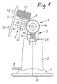
- 1 to 6 consists of a foot 1, a fixed column 2, a telescopic member 3, a first lockable hinge mechanism 4, a second lockable hinge mechanism 5 with orthogonal to the axis of the first hinge mechanism 4 arranged Axis, an intermediate member 6, which connects the two hinge mechanisms 4 and 5 together and a holding plate 7 for releasably receiving a device or device holder.
- the holding plate 7 is thus connected to the column 2 via an adjusting mechanism which comprises the two hinge mechanisms 4 and 5, the intermediate member 6 and the telescopic member 3 and thereby an adjustment by selectively pivoting about the two axes of the hinge mechanisms 4 and 5 and via the telescopic member 3 with regard to the distance from the foot 1 allows.
- the components of the retaining bracket are essentially all preferably made of plastic.
- the foot 1 is designed as a squeegee.
- the downwardly slightly over the housing of the foot 1 projecting suction membrane 11 can be seen.
- This suction diaphragm 11 is associated with an actuating mechanism which is arranged in the interior of the shaft-like column 2 and is known per se from the above-mentioned utility model DE 203 13 215 U1, but of course can also be modified from it.
- the actuating mechanism by means of which the squeegee, namely the suction diaphragm 11, is switchable between an effective and inoperative position, only the forward of an opening of the column 2 projecting actuating lever 8 is visible in the drawings.
- Whose lower position shown in the drawings corresponds to the effective position of the suction diaphragm 11, in which the central region is pulled upwards, so as to create a suction force generating vacuum space under the foot 1.
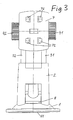
- the telescopic member 3 is guided. It consists in the illustrated embodiment of two parallel telescopic rails 31, 32 (see FIGS. 3, 4 and 5), which are each guided in the column 4 and the outside are provided with a rack profile 33, with one arranged in the upper region of the column 2 and thus integrally formed locking tab 21 cooperates resiliently.
- the arrangement is such that the telescopic member 3 can be moved relative to the column 2 when applying a corresponding force, in which case the holding force of the locking tab 21 is overcome and this ratchets accordingly over the rack profile 33.
- the locking tabs 21 arranged on both sides of the column 2 lock the telescopic member 3 by latching into the respective rack profile 33.
- the first hinge mechanism 4 comprises two screws 41 and 42 with knurled heads, which are inserted through holes in the free ends of the two telescopic rails 31, 32 and screwed into the ferrule 61 of the intermediate member 6. By tightening the screws 41, 42, the end sleeve 61 is clamped together with the respective telescopic rail 31, 32, so that thereby a clamping locking of the hinge mechanism 4 takes place.
- the second hinge mechanism 5 is by a forked end piece 62 of the intermediate member 2 in the embodiment three prongs, further by an inter-engaging bifurcated fitting 71 of the holding plate 7 with two prongs, and an aligned transverse bores of the prongs of the end piece 62 and the connecting piece 71 extending Screw 51 formed with knurled head, which screwed into a thread in the transverse bore of the knurled head of the screw 51 prongs of the end piece 62, which is formed in the region of the transverse bore to something thickened.
- the thread is formed in a metal nut which is inserted into the relevant telescopic rail.
- the holding plate 7 is provided on its upper side with an arrangement of 4 projecting, in cross-section each L-shaped retaining claws 72.
- a device holder for acceptance of a device of the type mentioned or possibly such a device can be fixed directly to the support plate 7.
- the retaining claws 72 engage in corresponding complementary slots at the bottom of the device holder or the device, where they are preferably received detent. So they form with the slots on the device holder or on the device a quick locking mechanism to attach the device holder or the device with a handle or to be able to remove.
- Fig. 6 shows the device holding console in the same side view as Fig. 2. Only the disposition of the retaining bracket is slightly changed.
- the intermediate piece 6 between the two rotary joint mechanisms 4 and 5 is in the retaining bracket in Fig. 6, namely considerably longer than in the retaining bracket in Fig. 2, and the adjusted pivot position of the intermediate piece 6 is slightly different from Fig. 2 and corresponds to that in FIG. 1.
- the intermediate piece 6 is easily exchangeable in the device holding console according to the invention. It only need the two screws 41, 42 of the hinge mechanism 4 and the screw 51 of the hinge mechanism 5 to be solved and pulled out to pull the connector 71 of the support plate 7 from the forked end piece 62 of the intermediate member 6 and the intermediate member 6 with its ferrule 61 from his Position between the ends of the telescopic rails 31, 32 to take out.
- the insertion of the intermediate member 6 is correspondingly simple.
- the device holding console is equipped with a plurality of, namely two or even 3 different pontics 6 different length, so that the user is a modular system with the possibility of selecting the appropriate distance between the two hinge mechanisms 4, 5 is available.
- the intermediate member 6 may be formed as a telescopic arm, but speak the simpler design and better stability for the solution according to the embodiment.
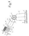
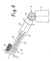
- FIGS. 7 and 8 show an alternative embodiment of the device holding console shown in FIGS. 1 to 6, the difference with respect to the arrangement according to FIGS. 1 to 6 being that the pivotable intermediate member 6 designed as a pivoting arm is designed as a telescopic member and consists of a telescopic element 63 connected to the hinge mechanism 4 and a telescopic element 64 connected to the hinge mechanism 5.
- a ratchet mechanism is preferably provided between those two telescoping members 63, 64 corresponding to those formed in the embodiment of FIGS. 1-6 from the rack 33 on each of the telescoping rails 31, 32 is and thus cooperating resilient locking tabs 21 formed on the column 2. Accordingly, in the embodiment according to FIGS.
- the hinge mechanism 4 is fixedly connected to the column 2.
- a combination of the two embodiments is possible, namely with a telescopic rail connection between the first hinge mechanism 4 and the column 2, as in the embodiments according to FIGS. 1 to 6, and in addition a telescopic formation of the intermediate member 6 according to The embodiment according to FIGS. 7 and 8.
- This makes it possible, especially if the console with the suction mechanism is attached to the disc in steep-sloping, far forward extending windshield, optimal positioning of the holding plate 7.
- a telescopic intermediate member 9 is connected to the column 2 via a double pivot mechanism 4, 5, 6.
- the double-pivot mechanism is formed as in the embodiment of Figures 1 to 5 and comprises a directly connected to the column 2 pivot mechanism 4, which is connected via a short intermediate member 6 with another hinge mechanism 5 with the hinge mechanism 4 orthogonal hinge axis.
- Both hinge mechanisms 4, 5 in turn have clamping screws 41 and 51 with knurled heads for clamping the hinge mechanism in the selected setting position.
- the telescopic intermediate member 9 consists of a telescopic element 91 connected to the hinge mechanism 5 and a telescoping element 92 telescoping and retractably cooperating therewith.
- the side view of FIG. 9 shows the fully inserted position of the telescoping elements 91, 92 shown in section, the plan view according to FIG. 10 shows the extended position.
- a ball socket 93 is arranged, in which a spherical counter element 73 of the holding plate 7 engages, which in turn is equipped with an arrangement of retaining claws 72.
- a likewise spherical clamping element 94 with a screw 95 biases this with a mobility enabling large recess provided spherical member 73 of the holding plate against the ball socket 93, wherein the screw 95 cooperates with a nut which sits in a knurled or profiled clamping wheel 96 which is inserted into a recess of the front part of the telescopic member 92, as the figures 9 and 10 show.
Abstract
Description
Die Erfindung betrifft eine Gerätehaltekonsole mit verstellbarer Halteplatte zur variablen bzw. einstellbaren Halterung von Kleingeräten wie Kleincomputern, wie sie üblicherweise unter der Bezeichnung "PDA" (Personal Digital Assistant) bekannt sind, mobile Navigationsgeräte, Funktelefone und dergleichen.The invention relates to a device holding console with adjustable support plate for variable or adjustable mounting of small devices such as small computers, as they are commonly known under the name "PDA" (Personal Digital Assistant), mobile navigation devices, radiotelephones and the like.
Eine derartige Gerätehaltekonsole findet insbesondere in Kraftfahrzeugen Anwendung, um Geräte der genannten Art an der Windschutzscheibe, am Armaturenbrett, an einer Mittelkonsole oder dergleichen in einer für die Benutzung des Geräts bequemen Orientierung zu halten, die je nach räumlicher Relation von Benutzer und Anbringungsort der Haltekonsole nach Bedarf einstellbar sein soll.Such device holding console is used in particular in motor vehicles application to keep devices of the type mentioned on the windshield, on the dashboard, on a center console or the like in a convenient for the use of the device orientation, depending on the spatial relationship of the user and mounting location of the retaining bracket after Need to be adjustable.
Aus der Gebrauchsmusterschrift DE 203 13 215 U1 ist bereits eine Gerätehaltekonsole bekannt, die eine Säule aufweist, die am einen Ende mit einem Fuß versehen ist und am anderen Ende über ein arretierbares Drehgelenk eine schwenkbare Halteplatte trägt, die mit Schnellbefestigungsorganen zum rastbaren Verbinden mit einem aufzunehmenden Gerät oder Gerätehalter versehen ist. Der Fuß ist als Saugfuß ausgebildet, und die Säule bildet einen Schacht, dessen Inneres den Betätigungsmechanismus für den Saugfuß aufnimmt, von welchem lediglich ein Betätigungshebel seitlich aus dem Schacht herausragt.From the utility model DE 203 13 215 U1 a device holding console is already known, which has a column which is provided at one end with a foot and at the other end via a lockable swivel bearing a pivotable mounting plate, which with snap fasteners for latchable connection with a male Device or device holder is provided. The foot is formed as a squeegee, and the column forms a shaft, the interior of which receives the actuating mechanism for the squeegee, from which only one actuating lever laterally protrudes from the shaft.
Aufgabe der vorliegenden Erfindung ist es, diese sehr vorteilhafte und zweckmäßige Gerätehaltekonsole im Hinblick auf eine universelle Verstellbarkeit der Halteplatte zu verbessern.Object of the present invention is to improve this very advantageous and convenient device holding console in terms of a universal adjustability of the holding plate.
Diese Aufgabe wird gemäß der Erfindung durch die im Anspruch 1 angegebene Anordnung gelöst. Vorteilhafte Ausgestaltungen und Weiterbildungen der Erfindung sind Gegenstand der Unteransprüche.This object is achieved according to the invention by the arrangement specified in
Erfindungsgemäß ist die Haltekonsole so ausgebildet, dass die Halteplatte nicht nur um zwei zueinander orthogonale Achsen und somit universell schwenkbar ist, sondern, bezogen auf eine jeweils gewählte Schwenkstellung, auch noch in ihrem Abstand vom Fuß veränderbar ist.According to the holding bracket is formed so that the holding plate is not only about two mutually orthogonal axes and thus universally pivotable, but based on a selected pivot position, even at their distance from the foot is changeable.
In einer Weiterbildung der Erfindung weist die erfindungsgemäße Haltekonsole auch noch ein baukastenartiges System von zwei oder mehr verschiedenen austauschbaren Zwischengliedern unterschiedlicher Länge zur Verbindung der beiden orthogonalen Schwenkachsen sowie formschlüssig wirkende Arretierungselemente zur drehmäßigen Arretierung in der gewählten Schwenkstellung auf, so dass zum einen eine größtmögliche Vielfalt der verfügbaren Einstellungen der Halteplatte und damit eine optimale Anpassbarkeit der Gerätehaltekonsole an die jeweils gegebenen räumlichen Verhältnisse gegeben ist, als auch eine größtmögliche Sicherheit gegen ungewollte Veränderung der gewählten Einstellung des zu haltenden Geräts auch bei heftigen Erschütterungen gewährleistet ist, wie sie beim Fahren eines Fahrzeuge über holprige Straßen nicht selten vorkommen.In a further development of the invention, the retaining bracket according to the invention also has a modular system of two or more different interchangeable pontics of different lengths for connecting the two orthogonal pivot axes and positively acting locking elements for rotational locking in the selected pivot position, so that on the one hand a maximum diversity of available settings of the retaining plate and thus optimal adaptability of the device support bracket is given to the given spatial conditions, as well as the greatest possible security against unwanted change in the selected setting of the device to be held even with violent shocks is ensured as they ride over a bumpy vehicle Roads are not uncommon.
Ein Ausführungsbeispiel der Erfindung wird nachstehend unter Bezugnahme auf die anliegenden Zeichnungen mehr im einzelnen beschrieben. In den Zeichnungen zeigt:
- Fig. 1
- eine Seitenansicht einer Gerätehaltekonsole nach der Erfindung,
- Fig. 2
- eine Seitenansicht der Gerätehaltekonsole ähnlich Fig. 1, jedoch in einer veränderten Einstellung der Halteplatte,
- Fig. 3
- eine Frontansicht der Gerätehaltekonsole in der Position nach Fig. 2,
- Fig. 4
- eine Rückansicht der Gerätehaltekonsole in der Position nach Fig. 2,
- Fig. 5
- eine Draufsicht auf die Gerätehaltekonsole in der Position nach Fig. 2,
- Fig. 6
- eine Seitenansicht der Gerätehaltekonsole mit ausgetauschtem, nämlich längerem Zwischenglied zwischen den Schwenkachsen,
- Fig. 7
- eine Seitenansicht einer abgewandelten Ausführungsform einer Gerätekonsole, wobei der Schwenkarm teleskopartig ausgebildet ist, mit eingefahrenem Teleskop-Schwenkarm,
- Fig. 8
- die Ausführungsform nach Fig. 7 mit ausgezogenem Teleskopschwenkarm,
- Fig. 9
- in teilgeschnittener Seitenansicht eine noch weitere Ausführungsform der Gerätehaltekonsole, und
- Fig. 10
- eine Draufsicht der Anordnung nach Fig. 9.
- Fig. 1
- a side view of a device holding console according to the invention,
- Fig. 2
- 2 a side view of the device holding console similar to FIG. 1, but in a modified setting of the holding plate,
- Fig. 3
- a front view of the device holding console in the position of Fig. 2,
- Fig. 4
- a rear view of the device holding console in position according to FIG. 2,
- Fig. 5
- a top view of the device holding console in the position of Fig. 2,
- Fig. 6
- a side view of the device holding console with exchanged, namely longer intermediate member between the pivot axes,
- Fig. 7
- a side view of a modified embodiment of a device console, wherein the pivot arm is telescopic, with retracted telescopic arm,
- Fig. 8
- 7 with extended telescopic pivoting arm,
- Fig. 9
- in a partially sectioned side view, a still further embodiment of the device holding console, and
- Fig. 10
- a plan view of the arrangement of FIG. 9th
Die in den Zeichnungen nach den Fig. 1 bis 6 dargestellte Gerätehaltekonsole besteht aus einem Fuß 1, einer darauf fest angeordneten Säule 2, einem Teleskopglied 3, einem ersten arretierbaren Drehgelenkmechanismus 4, einem zweiten arretierbaren Drehgelenkmechanismus 5 mit zur Achse des ersten Drehgelenkmechanismus 4 orthogonal angeordneter Achse, einem Zwischenglied 6, das die beiden Drehgelenkmechanismen 4 und 5 miteinander verbindet und einer Halteplatte 7 zur lösbaren Aufnahme eines Geräts oder Gerätehalters. Die Halteplatte 7 ist mit der Säule 2 also über einen Verstellmechanismus verbunden, der die beiden Drehgelenkmechanismen 4 und 5, das Zwischenglied 6 und das Teleskopglied 3 umfaßt und dadurch eine Verstellung durch wahlweises Schwenken um die beiden Achsen der Drehgelenkmechanismen 4 und 5 sowie über das Teleskopglied 3 hinsichtlich der Distanz vom Fuß 1 ermöglicht. Die Bauteile der Haltekonsole bestehen im wesentlichen alle vorzugsweise aus Kunststoff.1 to 6 consists of a
Der Fuß 1 ist als Saugfuß ausgebildet. In den Zeichnungen ist die nach unten leicht über das Gehäuse des Fußes 1 überstehende Saugmembran 11 erkennbar. Dieser Saugmembran 11 ist ein Betätigungsmechanismus zugeordnet, der im Inneren der schachtartig ausgebildeten Säule 2 angeordnet und an sich aus der eingangs erwähnten Gebrauchsmusterschrift DE 203 13 215 U1 bekannt ist, aber natürlich auch davon abgewandelt ausgeführt sein kann. Von dem Betätigungsmechanismus, mittels dessen der Saugfuß, nämlich die Saugmembran 11, zwischen einer wirksamen und unwirksamen Position umschaltbar ist, ist in den Zeichnungen nur der nach vorne aus einer Öffnung der Säule 2 herausragende Betätigungshebel 8 sichtbar. Dessen in den Zeichnungen dargestellte untere Stellung entspricht der wirksamen Stellung der Saugmembran 11, in welcher deren Zentralbereich nach oben gezogen ist, um so einen eine Saugkraft erzeugenden Unterdruckraum unter dem Fuß 1 zu schaffen.The
In der Säule 2 ist das Teleskopglied 3 geführt. Es besteht beim dargestellten Ausführungsbeispiel aus zwei parallelen Teleskopschienen 31, 32 (siehe Fig. 3, 4 und 5), die jeweils in der Säule 4 geführt sind und außenseitig mit einem Zahnstangenprofil 33 versehen sind, mit dem eine im oberen Bereich der Säule 2 angeordnete und damit einstückig ausgebildete Rastlasche 21 federnd zusammenwirkt. Die Anordnung ist so getroffen, dass das Teleskopglied 3 sich bei Anwenden einer entsprechenden Kraft relativ zur Säule 2 verschieben lässt, wobei dann die Haltekraft der Rastlasche 21 überwunden wird und diese entsprechend über das Zahnstangenprofil 33 ratscht. In der jeweils gewählten Auszugsposition arretieren die auf beiden Seiten der Säule 2 angeordneten Rastlaschen 21 das Teleskopglied 3 durch Einrasten in das jeweilige Zahnstangenprofil 33.In the
Der erste Drehgelenkmechanismus 4 umfaßt zwei Schrauben 41 und 42 mit gerändelten Köpfen, die durch Bohrungen der freien Enden der beiden Teleskopschienen 31, 32 hindurchgesteckt und in die Endhülse 61 des Zwischenglieds 6 eingeschraubt sind. Durch Festdrehen der Schrauben 41, 42 wird die Endhülse 61 mit der jeweiligen Teleskopschiene 31, 32 zusammengespannt, so dass dadurch eine klemmende Arretierung des Drehgelenkmechanismus 4 erfolgt.The
Vorzugsweise ist (das ist in den Zeichnungen nicht sichtbar) an den axialen Stirnseiten der Endhülse 61 und den diesen zugewandten Innenseiten der Teleskopschienen 31, 32 jeweils radiale Zahnprofile gebildet, die eine formschlüssige Arretierung des Drehgelenkmechanismus beim Festdrehen der Schrauben 41, 42 gewährleisten.Preferably (this is not visible in the drawings) at the axial end faces of the
Der zweite Drehgelenkmechanismus 5 ist durch ein gegabeltes Endstück 62 des Zwischenglieds 2 mit beim Ausführungsbeispiel drei Zinken, weiter durch ein zwischen diese greifendes gegabeltes Anschlussstück 71 der Halteplatte 7 mit zwei Zinken, und eine durch fluchtende Querbohrungen der Zinken des Endstücks 62 und des Anschlussstücks 71 verlaufende Schraube 51 mit gerändeltem Kopf gebildet, die in ein Gewinde in der Querbohrung des vom Rändelkopf der Schraube 51 entfernten Zinken des Endstücks 62 eingeschraubt, der im Bereich der Querbohrung dazu etwas verdickt ausgebildet ist. Zweckmäßigerweise ist das Gewinde in einer Metallmutter gebildet, die in die betreffende Teleskopschiene eingesetzt ist.The
Beim Festdrehen der Schraube 51 werden die ineinandergreifenden Zinken des Endstücks 62 und des Anschlussstücks 71 zusammengespannt, so dass sich eine reibschlüssige Arretierung des Drehgelenkmechanismus 5 in der jeweils gewählten Schwenkposition der Halteplatte 7 ergibt. Es versteht sich, dass auch bei diesem Drehgelenkmechanismus eine zusätzliche Formschlussarretierung herstellen lässt wie beim Drehgelenkmechanismus 4, jedoch wird dies im Hinblick auf den sehr kurzen Hebelarm zwischen der Achse des Drehgelenkmechanismus 5 und der Halteplatte 7 im allgemeinen nicht notwendig sein.When tightening the
Die Halteplatte 7 ist an ihrer Oberseite mit einer Anordnung von 4 vorstehenden, im Querschnitt jeweils L-förmigen Haltekrallen 72 versehen. Damit kann ein Gerätehalter zur Auf nahme eines Geräts der eingangs genannten Art oder ggf. ein solches Gerät auch unmittelbar an der Halteplatte 7 fixiert werden. Die Haltekrallen 72 greifen dabei in entsprechende komplementäre Schlitze am Boden des Gerätehalters oder des Geräts ein, wo sie vorzugsweise rastend aufgenommen werden. Sie bilden also mit den Schlitzen am Gerätehalter bzw. am Gerät einen Schnellverriegelungsmechanismus, um den Gerätehalter bzw. das Gerät mit einem Handgriff anbringen oder abnehmen zu können.The holding
Fig. 6 zeigt die Gerätehaltekonsole in der gleichen Seitenansicht wie Fig. 2. Nur die Disposition der Haltekonsole ist etwas verändert. Das Zwischenstück 6 zwischen den beiden Drehgelenkmechanismen 4 und 5 ist bei der Haltekonsole in Fig. 6 nämlich erheblich länger als bei der Haltekonsole in Fig. 2, und die eingestellte Schwenkstellung des Zwischenstücks 6 ist gegenüber Fig. 2 etwas verändert und entspricht derjenigen in Fig. 1.Fig. 6 shows the device holding console in the same side view as Fig. 2. Only the disposition of the retaining bracket is slightly changed. The
Das Zwischenstück 6 ist nämlich bei der Gerätehaltekonsole nach der Erfindung leicht austauschbar ausgebildet. Es brauchen nur die beiden Schrauben 41, 42 des Drehgelenkmechanismus 4 sowie die Schraube 51 des Drehgelenkmechanismus 5 gelöst und herausgezogen zu werden, um das Anschlussstück 71 der Halteplatte 7 vom gegabelten Endstück 62 des Zwischenglieds 6 abziehen und das Zwischenglied 6 mit seiner Endhülse 61 aus seiner Position zwischen den Enden der Teleskopschienen 31, 32 herausnehmen zu können. Das Einsetzen des Zwischenglieds 6 erfolgt entsprechend einfach. Vorzugsweise ist die Gerätehaltekonsole mit mehreren, nämlich zwei oder sogar 3 verschiedenen Zwischengliedern 6 unterschiedlicher Länge ausgestattet, so dass dem Benutzer ein baukastenartiges System mit der Möglichkeit der Auswahl der jeweils geeigneten Distanz zwischen den beiden Drehgelenkmechanismen 4, 5 zur Verfügung steht. Es versteht sich, dass alternativ dazu auch das Zwischenglied 6 als Teleskoparm ausgebildet sein kann, jedoch sprechen die einfachere Gestaltung und die bessere Stabilität für die Lösung nach dem Ausführungsbeispiel.Namely, the
Die Fig. 7 und 8 zeigen eine alternative Ausführungsform der in den Fig. 1 bis 6 gezeigten Gerätehaltekonsole, wobei der Unterschied gegenüber der Anordnung nach den Fig. 1 bis 6 darin besteht, dass das als Schwenkarm ausgebildete schwenkbare Zwischenglied 6 als Teleskopglied ausgebildet ist und aus einem mit dem Drehgelenkmechanismus 4 verbundenen Teleskopelement 63 und einem mit dem Drehgelenkmechanismus 5 verbundenen Teleskopelement 64 besteht. Obwohl dies in den schematisch dargestellten Zeichnungen nicht eigens gezeigt ist, ist zwischen diesen beiden Teleskopelementen 63, 64 vorzugsweise ein Ratschenmechanismus entsprechend denjenigen vorgesehen, der bei der Ausführungsform nach den Fig. 1 bis 6 aus der Zahnstange 33 an jeder der Teleskopschienen 31, 32 gebildet ist und damit zusammenwirkenden federnden Rastlaschen 21 an der Säule 2 gebildet ist. Dementsprechend ist bei der Ausführungsform nach den Fig. 7 und 8 ebenfalls vorzugsweise an gegenüberliegenden Seiten des Teleskopelements 64 jeweils eine Zahnstange 65 gebildet, die mit einer federnden Rastlasche 66 des Teleskopelements 64 zusammenwirkt. Damit wird eine größtmögliche Stabilität und Schwingungsfreiheit des so längenveränderlich ausgebildeten Zwischenglieds 6 erreicht.FIGS. 7 and 8 show an alternative embodiment of the device holding console shown in FIGS. 1 to 6, the difference with respect to the arrangement according to FIGS. 1 to 6 being that the pivotable
Bei der Ausführungsform nach den Fig. 7 und 8 ist der Drehgelenkmechanismus 4 fest mit der Säule 2 verbunden. Es versteht sich aber, dass auch eine Kombination der beiden Ausführungsformen möglich ist, nämlich mit einer Teleskopschienenverbindung zwischen dem ersten Drehgelenkmechanismus 4 und der Säule 2, wie bei den Ausführungsformen nach den Fig. 1 bis 6, und zusätzlich einer teleskopartigen Ausbildung des Zwischenglieds 6 nach der Ausführungsform gemäß den Fig. 7 und 8. Damit lässt sich, insbesondere wenn in Fahrzeugen der Oberklasse mit stark geneigter, sich weit nach vorne erstreckender Windschutzscheibe die Konsole mit dem Saugmechanismus an der Scheibe angebracht wird, eine optimale Positionierbarkeit der Halteplatte 7.In the embodiment according to FIGS. 7 and 8, the
Die Ausführungsform nach den Figuren 9 und 10 bietet nochmals besonders universelle und stabile Einstellmöglichkeiten. Bei dieser Ausführungsform ist ein Teleskop-Zwischenglied 9 über einen Doppeldrehgelenkmechanismus 4, 5, 6 mit der Säule 2 verbunden. Der Doppeldrehgelenkmechanismus ist wie bei der Ausführungsform nach den Figuren 1 bis 5 ausgebildet und umfasst einen direkt mit der Säule 2 verbundenen Drehgelenkmechanismus 4, der über ein kurzes Zwischenglied 6 mit einem weiteren Drehgelenkmechanismus 5 mit zum Drehgelenkmechanismus 4 orthogonaler Gelenkachse verbunden ist. Beide Drehgelenkmechanismen 4, 5 weisen wiederum Klemmschrauben 41 bzw. 51 mit gerändelten Köpfen zum Festspannen des Gelenkmechanismus in der jeweils gewählten Einstellposition auf. Das Teleskop-Zwischenglied 9 besteht aus einem mit dem Gelenkmechanismus 5 verbundenen Teleskopelement 91 und einem damit rastbar zusammenwirkenden auszieh- und einschiebbaren Teleskopelement 92. Die Seitenansicht nach Figur 9 zeigt die vollständig eingeschobene Position der geschnitten dargestellten Teleskopelemente 91, 92, die Draufsicht nach Fig. 10 zeigt die ausgezogene Position.The embodiment according to FIGS. 9 and 10 once again offers particularly universal and stable adjustment possibilities. In this embodiment, a telescopic intermediate member 9 is connected to the
Am vorderen Ende des ausziehbaren Teleskopelements 92 ist eine Kugelpfanne 93 angeordnet, in welche ein kugeliges Gegenelement 73 der Halteplatte 7 eingreift, die wiederum mit einer Anordnung von Haltekrallen 72 ausgestattet ist. Ein ebenfalls kugeliges Spannelement 94 mit einer Schraube 95 spannt das mit einer die Beweglichkeit ermöglichenden großen Aussparung versehene kugelige Element 73 der Halteplatte gegen die Kugelpfanne 93, wobei die Schraube 95 mit einer Mutter zusammenwirkt, die in einem gerändelten oder profiliertem Klemmrad 96 sitzt, das in eine Aussparung des vorderen Teils des Teleskopelements 92 eingesetzt ist, wie die Figuren 9 und 10 zeigen.At the front end of the extendable
Es versteht sich, daß über die in den Zeichnungen dargestellten und vorstehend beschriebenen Ausführungsbeispiele hinaus noch weitere Ausführungsvarianten möglich sind, insbesondere hinsichtlich der jeweiligen Gelenkausbildungen. Allerdings erscheinen gegenwärtig die dargestellten und beschriebenen Ausführungsformen als im Hinblick auf eine größtmögliche Stabilität und Flexibilität der Einstellung besonders vorteilhaft.It is understood that in addition to the embodiments shown in the drawings and described above, further variants are possible, in particular with regard to the respective joint formations. However, at present, the illustrated and described embodiments appear to be particularly advantageous in terms of maximum stability and flexibility of adjustment.
Claims (14)
dadurch gekennzeichnet, dass der Gelenkmechanismus (4, 5) mit einem Teleskopglied (3) verbunden ist, das in der Säule (2) geführt und wahlweise bis um eine konstruktionsbedingte Maximaldistanz aus der Säule (2) ausziehbar sowie in der jeweils gewählten Auszugsposition arretierbar (21, 33) ist,
und/oder die Halteplatte (7) über ein aus zwei ineinander schiebbaren und bis um eine konstruktionsbedingte Maximaldistanz relativ zueinander ausziehbaren Teleskopelementen (63, 64; 91, 92) gebildetes und in der jeweils gewählten Auszugsposition arretierbares (65, 66) Zwischenglied (6; 9) mit dem Gelenkmechanismus (4; 5) verbunden ist.Device holding console with a foot (1), a pillar (2) and a holding plate (7) connected therewith via a lockable joint mechanism (4, 5) for mounting an appliance holder or device,
characterized in that the hinge mechanism (4, 5) is connected to a telescopic member (3) which is guided in the column (2) and optionally extendable up to a design-related maximum distance from the column (2) and lockable in the selected selected position ( 21, 33),
and / or the retaining plate (7) via a two telescoping and up to a design-related maximum distance relative telescopically telescoping telescopic elements (63, 64, 91, 92) formed and in the selected selected position lockable (65, 66) intermediate member (6; 9) is connected to the hinge mechanism (4; 5).
Applications Claiming Priority (2)
| Application Number | Priority Date | Filing Date | Title |
|---|---|---|---|
| DE202004018511 | 2004-11-29 | ||
| DE200520000768 DE202005000768U1 (en) | 2004-11-29 | 2005-01-18 | Device with universally adjustable retaining plate |
Publications (3)
| Publication Number | Publication Date |
|---|---|
| EP1666308A2 true EP1666308A2 (en) | 2006-06-07 |
| EP1666308A3 EP1666308A3 (en) | 2006-09-13 |
| EP1666308B1 EP1666308B1 (en) | 2008-03-12 |
Family
ID=35478480
Family Applications (1)
| Application Number | Title | Priority Date | Filing Date |
|---|---|---|---|
| EP05007356A Not-in-force EP1666308B1 (en) | 2004-11-29 | 2005-04-05 | Universally adjustable device console. |
Country Status (3)
| Country | Link |
|---|---|
| EP (1) | EP1666308B1 (en) |
| AT (1) | ATE388856T1 (en) |
| DE (1) | DE502005003184D1 (en) |
Cited By (4)
| Publication number | Priority date | Publication date | Assignee | Title |
|---|---|---|---|---|
| EP1881257A1 (en) | 2006-07-21 | 2008-01-23 | Bury Sp.z.o.o | Supporting arm with a suction cup and a holder for attaching various equipment within the mechanical vehicles |
| WO2009066282A1 (en) * | 2007-11-19 | 2009-05-28 | I. Way Mobile Ltd. | Designed console for providing a variety of cellular services to a driver of a motor vehicle and his environment |
| CN102297329A (en) * | 2010-06-24 | 2011-12-28 | 昆达电脑科技(昆山)有限公司 | Support mechanism |
| CN110254362A (en) * | 2019-06-18 | 2019-09-20 | 浙江吉利控股集团有限公司 | Large-size screen monitors assembly is controlled in a kind of adjustable automobiles |
Citations (1)
| Publication number | Priority date | Publication date | Assignee | Title |
|---|---|---|---|---|
| DE20313215U1 (en) | 2003-08-25 | 2003-10-16 | Richter Herbert | holder |
Family Cites Families (9)
| Publication number | Priority date | Publication date | Assignee | Title |
|---|---|---|---|---|
| JPS63300698A (en) * | 1987-05-29 | 1988-12-07 | Fujitsu Ltd | Structure of freely attachable metallic fixture |
| US5779205A (en) * | 1996-12-23 | 1998-07-14 | Ching; Allen | Extensible windshield portable phone holder |
| US6220556B1 (en) * | 1999-05-28 | 2001-04-24 | Thomas M. Sohrt | Universally adjustable mounting system for switches, or the like |
| US6213438B1 (en) * | 1999-12-16 | 2001-04-10 | Ostby Leroy M. | Computer support for vehicle use having multiple position adjustments |
| DE20010071U1 (en) * | 2000-06-05 | 2000-08-17 | Huang Lin Wei | Device for holding a mobile phone |
| US6390424B1 (en) * | 2000-07-13 | 2002-05-21 | Margo Kidushim | Accessory support device and method |
| DE10132039C2 (en) * | 2001-07-03 | 2003-06-18 | Bernd Gierth | Holder for a laptop in the car |
| DE10311112A1 (en) * | 2003-03-12 | 2004-09-23 | Herbert Richter Metallwaren-Apparatebau Gmbh & Co | vacuum cups |
| DE202004005825U1 (en) * | 2004-04-08 | 2004-06-24 | Audioton Kabelwerk Gmbh Zweigniederlassung Scheinfeld | Holder for a mobile radio device such as a mobile telephone or a personal digital assistant for hands free operation in a car or the like and including a locating antenna |
-
2005
- 2005-04-05 DE DE502005003184T patent/DE502005003184D1/en active Active
- 2005-04-05 AT AT05007356T patent/ATE388856T1/en active
- 2005-04-05 EP EP05007356A patent/EP1666308B1/en not_active Not-in-force
Patent Citations (1)
| Publication number | Priority date | Publication date | Assignee | Title |
|---|---|---|---|---|
| DE20313215U1 (en) | 2003-08-25 | 2003-10-16 | Richter Herbert | holder |
Cited By (6)
| Publication number | Priority date | Publication date | Assignee | Title |
|---|---|---|---|---|
| EP1881257A1 (en) | 2006-07-21 | 2008-01-23 | Bury Sp.z.o.o | Supporting arm with a suction cup and a holder for attaching various equipment within the mechanical vehicles |
| WO2009066282A1 (en) * | 2007-11-19 | 2009-05-28 | I. Way Mobile Ltd. | Designed console for providing a variety of cellular services to a driver of a motor vehicle and his environment |
| CN101868961A (en) * | 2007-11-19 | 2010-10-20 | 艾维移动有限公司 | Designed console for providing a variety of cellular services to a driver of a motor vehicle and his environment |
| JP2011505286A (en) * | 2007-11-19 | 2011-02-24 | アイ. ウェイ モバイル リミテッド | A console designed to provide various cellular services to car drivers and their environment |
| CN102297329A (en) * | 2010-06-24 | 2011-12-28 | 昆达电脑科技(昆山)有限公司 | Support mechanism |
| CN110254362A (en) * | 2019-06-18 | 2019-09-20 | 浙江吉利控股集团有限公司 | Large-size screen monitors assembly is controlled in a kind of adjustable automobiles |
Also Published As
| Publication number | Publication date |
|---|---|
| EP1666308B1 (en) | 2008-03-12 |
| ATE388856T1 (en) | 2008-03-15 |
| DE502005003184D1 (en) | 2008-04-24 |
| EP1666308A3 (en) | 2006-09-13 |
Similar Documents
| Publication | Publication Date | Title |
|---|---|---|
| EP2769647B1 (en) | Child's high chair | |
| DE60128109T2 (en) | DEVICE FOR FIXING TELESCOPIC COMPONENT ELEMENTS | |
| DE4323575C2 (en) | Safety pedal for a bicycle or the like | |
| EP0526775A1 (en) | Holding device for shower head | |
| EP1829749A1 (en) | Device holder with flexible replaceable support arm | |
| EP1688659A2 (en) | Universal joint device between an apparatus holder and a supporting arm or a console | |
| DE10147588A1 (en) | Fastening block for holding objects on a profile rail | |
| WO2013152365A1 (en) | Adjusting device for adjusting a position of a drawer | |
| WO2008006577A1 (en) | Coupling device for attaching an accessory or a luggage holding unit in the front region of a bicycle | |
| EP2272437B1 (en) | Surgical spreading instrument | |
| EP1131140A1 (en) | Stick such as a ski-stick, walking stick or same | |
| EP1666308B1 (en) | Universally adjustable device console. | |
| WO2006125653A1 (en) | Connection between two tool parts | |
| DE102006037583A1 (en) | Steering column with easy-entry and memory function | |
| EP2135803A1 (en) | Mudguard for a bicycle | |
| DE10206780B4 (en) | Fastening device for a child seat | |
| DE202007008827U1 (en) | Door handle system comprises door mounting plate has bearing sleeve, into which cylindrical bearing section on handle fits, bearing and sleeve having recesses, into which ends of return spring fit | |
| EP1297765A1 (en) | A device for the tool-less mounting and dismounting of a furniture drawer front panel | |
| EP1264587B1 (en) | Walking aid | |
| DE69906650T2 (en) | Control device of an adjustable part of a motor vehicle headlight | |
| EP0841033A2 (en) | Telescopic vacuum cleaner suction hose | |
| EP0704580B1 (en) | Shower fitting with adjustable clamping element | |
| DE10047633A1 (en) | Clamp for sun- or vision-screen support has angled holder with two arms, threaded spindle, clamping element with container part and threaded sections on arm | |
| DE806761C (en) | Control levers on vehicles, cranes, etc. Like., In particular on motor vehicles | |
| DE8010197U1 (en) | HANDLE FOR GARDEN EQUIPMENT |
Legal Events
| Date | Code | Title | Description |
|---|---|---|---|
| PUAI | Public reference made under article 153(3) epc to a published international application that has entered the european phase |
Free format text: ORIGINAL CODE: 0009012 |
|
| AK | Designated contracting states |
Kind code of ref document: A2 Designated state(s): AT BE BG CH CY CZ DE DK EE ES FI FR GB GR HU IE IS IT LI LT LU MC NL PL PT RO SE SI SK TR |
|
| AX | Request for extension of the european patent |
Extension state: AL BA HR LV MK YU |
|
| PUAL | Search report despatched |
Free format text: ORIGINAL CODE: 0009013 |
|
| AK | Designated contracting states |
Kind code of ref document: A3 Designated state(s): AT BE BG CH CY CZ DE DK EE ES FI FR GB GR HU IE IS IT LI LT LU MC NL PL PT RO SE SI SK TR |
|
| AX | Request for extension of the european patent |
Extension state: AL BA HR LV MK YU |
|
| 17P | Request for examination filed |
Effective date: 20070309 |
|
| AKX | Designation fees paid |
Designated state(s): AT BE BG CH CY CZ DE DK EE ES FI FR GB GR HU IE IS IT LI LT LU MC NL PL PT RO SE SI SK TR |
|
| GRAP | Despatch of communication of intention to grant a patent |
Free format text: ORIGINAL CODE: EPIDOSNIGR1 |
|
| GRAS | Grant fee paid |
Free format text: ORIGINAL CODE: EPIDOSNIGR3 |
|
| GRAA | (expected) grant |
Free format text: ORIGINAL CODE: 0009210 |
|
| AK | Designated contracting states |
Kind code of ref document: B1 Designated state(s): AT BE BG CH CY CZ DE DK EE ES FI FR GB GR HU IE IS IT LI LT LU MC NL PL PT RO SE SI SK TR |
|
| REG | Reference to a national code |
Ref country code: GB Ref legal event code: FG4D Free format text: NOT ENGLISH |
|
| REG | Reference to a national code |
Ref country code: CH Ref legal event code: EP |
|
| GBT | Gb: translation of ep patent filed (gb section 77(6)(a)/1977) |
Effective date: 20080312 |
|
| REG | Reference to a national code |
Ref country code: IE Ref legal event code: FG4D Free format text: LANGUAGE OF EP DOCUMENT: GERMAN |
|
| REF | Corresponds to: |
Ref document number: 502005003184 Country of ref document: DE Date of ref document: 20080424 Kind code of ref document: P |
|
| PG25 | Lapsed in a contracting state [announced via postgrant information from national office to epo] |
Ref country code: FI Free format text: LAPSE BECAUSE OF FAILURE TO SUBMIT A TRANSLATION OF THE DESCRIPTION OR TO PAY THE FEE WITHIN THE PRESCRIBED TIME-LIMIT Effective date: 20080312 Ref country code: LT Free format text: LAPSE BECAUSE OF FAILURE TO SUBMIT A TRANSLATION OF THE DESCRIPTION OR TO PAY THE FEE WITHIN THE PRESCRIBED TIME-LIMIT Effective date: 20080312 |
|
| PG25 | Lapsed in a contracting state [announced via postgrant information from national office to epo] |
Ref country code: PL Free format text: LAPSE BECAUSE OF FAILURE TO SUBMIT A TRANSLATION OF THE DESCRIPTION OR TO PAY THE FEE WITHIN THE PRESCRIBED TIME-LIMIT Effective date: 20080312 Ref country code: SI Free format text: LAPSE BECAUSE OF FAILURE TO SUBMIT A TRANSLATION OF THE DESCRIPTION OR TO PAY THE FEE WITHIN THE PRESCRIBED TIME-LIMIT Effective date: 20080312 |
|
| REG | Reference to a national code |
Ref country code: IE Ref legal event code: FD4D |
|
| PG25 | Lapsed in a contracting state [announced via postgrant information from national office to epo] |
Ref country code: SK Free format text: LAPSE BECAUSE OF FAILURE TO SUBMIT A TRANSLATION OF THE DESCRIPTION OR TO PAY THE FEE WITHIN THE PRESCRIBED TIME-LIMIT Effective date: 20080312 Ref country code: CZ Free format text: LAPSE BECAUSE OF FAILURE TO SUBMIT A TRANSLATION OF THE DESCRIPTION OR TO PAY THE FEE WITHIN THE PRESCRIBED TIME-LIMIT Effective date: 20080312 Ref country code: ES Free format text: LAPSE BECAUSE OF FAILURE TO SUBMIT A TRANSLATION OF THE DESCRIPTION OR TO PAY THE FEE WITHIN THE PRESCRIBED TIME-LIMIT Effective date: 20080623 Ref country code: PT Free format text: LAPSE BECAUSE OF FAILURE TO SUBMIT A TRANSLATION OF THE DESCRIPTION OR TO PAY THE FEE WITHIN THE PRESCRIBED TIME-LIMIT Effective date: 20080818 Ref country code: SE Free format text: LAPSE BECAUSE OF FAILURE TO SUBMIT A TRANSLATION OF THE DESCRIPTION OR TO PAY THE FEE WITHIN THE PRESCRIBED TIME-LIMIT Effective date: 20080612 |
|
| ET | Fr: translation filed | ||
| PG25 | Lapsed in a contracting state [announced via postgrant information from national office to epo] |
Ref country code: MC Free format text: LAPSE BECAUSE OF NON-PAYMENT OF DUE FEES Effective date: 20080430 Ref country code: RO Free format text: LAPSE BECAUSE OF FAILURE TO SUBMIT A TRANSLATION OF THE DESCRIPTION OR TO PAY THE FEE WITHIN THE PRESCRIBED TIME-LIMIT Effective date: 20080312 |
|
| PG25 | Lapsed in a contracting state [announced via postgrant information from national office to epo] |
Ref country code: IS Free format text: LAPSE BECAUSE OF FAILURE TO SUBMIT A TRANSLATION OF THE DESCRIPTION OR TO PAY THE FEE WITHIN THE PRESCRIBED TIME-LIMIT Effective date: 20080712 |
|
| PLBE | No opposition filed within time limit |
Free format text: ORIGINAL CODE: 0009261 |
|
| STAA | Information on the status of an ep patent application or granted ep patent |
Free format text: STATUS: NO OPPOSITION FILED WITHIN TIME LIMIT |
|
| PG25 | Lapsed in a contracting state [announced via postgrant information from national office to epo] |
Ref country code: DK Free format text: LAPSE BECAUSE OF FAILURE TO SUBMIT A TRANSLATION OF THE DESCRIPTION OR TO PAY THE FEE WITHIN THE PRESCRIBED TIME-LIMIT Effective date: 20080312 Ref country code: EE Free format text: LAPSE BECAUSE OF FAILURE TO SUBMIT A TRANSLATION OF THE DESCRIPTION OR TO PAY THE FEE WITHIN THE PRESCRIBED TIME-LIMIT Effective date: 20080312 Ref country code: IE Free format text: LAPSE BECAUSE OF FAILURE TO SUBMIT A TRANSLATION OF THE DESCRIPTION OR TO PAY THE FEE WITHIN THE PRESCRIBED TIME-LIMIT Effective date: 20080312 |
|
| 26N | No opposition filed |
Effective date: 20081215 |
|
| PG25 | Lapsed in a contracting state [announced via postgrant information from national office to epo] |
Ref country code: BG Free format text: LAPSE BECAUSE OF FAILURE TO SUBMIT A TRANSLATION OF THE DESCRIPTION OR TO PAY THE FEE WITHIN THE PRESCRIBED TIME-LIMIT Effective date: 20080612 |
|
| PG25 | Lapsed in a contracting state [announced via postgrant information from national office to epo] |
Ref country code: IT Free format text: LAPSE BECAUSE OF FAILURE TO SUBMIT A TRANSLATION OF THE DESCRIPTION OR TO PAY THE FEE WITHIN THE PRESCRIBED TIME-LIMIT Effective date: 20080312 |
|
| PG25 | Lapsed in a contracting state [announced via postgrant information from national office to epo] |
Ref country code: CY Free format text: LAPSE BECAUSE OF FAILURE TO SUBMIT A TRANSLATION OF THE DESCRIPTION OR TO PAY THE FEE WITHIN THE PRESCRIBED TIME-LIMIT Effective date: 20080312 |
|
| PG25 | Lapsed in a contracting state [announced via postgrant information from national office to epo] |
Ref country code: HU Free format text: LAPSE BECAUSE OF FAILURE TO SUBMIT A TRANSLATION OF THE DESCRIPTION OR TO PAY THE FEE WITHIN THE PRESCRIBED TIME-LIMIT Effective date: 20080913 Ref country code: LU Free format text: LAPSE BECAUSE OF NON-PAYMENT OF DUE FEES Effective date: 20080405 |
|
| PG25 | Lapsed in a contracting state [announced via postgrant information from national office to epo] |
Ref country code: TR Free format text: LAPSE BECAUSE OF FAILURE TO SUBMIT A TRANSLATION OF THE DESCRIPTION OR TO PAY THE FEE WITHIN THE PRESCRIBED TIME-LIMIT Effective date: 20080312 |
|
| PG25 | Lapsed in a contracting state [announced via postgrant information from national office to epo] |
Ref country code: GR Free format text: LAPSE BECAUSE OF FAILURE TO SUBMIT A TRANSLATION OF THE DESCRIPTION OR TO PAY THE FEE WITHIN THE PRESCRIBED TIME-LIMIT Effective date: 20080613 |
|
| PGFP | Annual fee paid to national office [announced via postgrant information from national office to epo] |
Ref country code: CH Payment date: 20110421 Year of fee payment: 7 |
|
| PGFP | Annual fee paid to national office [announced via postgrant information from national office to epo] |
Ref country code: BE Payment date: 20110419 Year of fee payment: 7 |
|
| PGFP | Annual fee paid to national office [announced via postgrant information from national office to epo] |
Ref country code: NL Payment date: 20120425 Year of fee payment: 8 |
|
| PGFP | Annual fee paid to national office [announced via postgrant information from national office to epo] |
Ref country code: GB Payment date: 20120423 Year of fee payment: 8 Ref country code: FR Payment date: 20120511 Year of fee payment: 8 |
|
| BERE | Be: lapsed |
Owner name: RICHTER, HARALD Effective date: 20120430 |
|
| REG | Reference to a national code |
Ref country code: CH Ref legal event code: PL |
|
| PG25 | Lapsed in a contracting state [announced via postgrant information from national office to epo] |
Ref country code: CH Free format text: LAPSE BECAUSE OF NON-PAYMENT OF DUE FEES Effective date: 20120430 Ref country code: BE Free format text: LAPSE BECAUSE OF NON-PAYMENT OF DUE FEES Effective date: 20120430 Ref country code: LI Free format text: LAPSE BECAUSE OF NON-PAYMENT OF DUE FEES Effective date: 20120430 |
|
| PGFP | Annual fee paid to national office [announced via postgrant information from national office to epo] |
Ref country code: AT Payment date: 20120420 Year of fee payment: 8 |
|
| REG | Reference to a national code |
Ref country code: NL Ref legal event code: V1 Effective date: 20131101 |
|
| REG | Reference to a national code |
Ref country code: AT Ref legal event code: MM01 Ref document number: 388856 Country of ref document: AT Kind code of ref document: T Effective date: 20130430 |
|
| GBPC | Gb: european patent ceased through non-payment of renewal fee |
Effective date: 20130405 |
|
| PG25 | Lapsed in a contracting state [announced via postgrant information from national office to epo] |
Ref country code: AT Free format text: LAPSE BECAUSE OF NON-PAYMENT OF DUE FEES Effective date: 20130430 Ref country code: GB Free format text: LAPSE BECAUSE OF NON-PAYMENT OF DUE FEES Effective date: 20130405 |
|
| REG | Reference to a national code |
Ref country code: FR Ref legal event code: ST Effective date: 20131231 |
|
| PG25 | Lapsed in a contracting state [announced via postgrant information from national office to epo] |
Ref country code: NL Free format text: LAPSE BECAUSE OF NON-PAYMENT OF DUE FEES Effective date: 20131101 Ref country code: FR Free format text: LAPSE BECAUSE OF NON-PAYMENT OF DUE FEES Effective date: 20130430 |
|
| PGFP | Annual fee paid to national office [announced via postgrant information from national office to epo] |
Ref country code: DE Payment date: 20150615 Year of fee payment: 11 |
|
| REG | Reference to a national code |
Ref country code: DE Ref legal event code: R119 Ref document number: 502005003184 Country of ref document: DE |
|
| PG25 | Lapsed in a contracting state [announced via postgrant information from national office to epo] |
Ref country code: DE Free format text: LAPSE BECAUSE OF NON-PAYMENT OF DUE FEES Effective date: 20161101 |