EP1684387A1 - Earth terminal fitting and electric connector having the same - Google Patents
Earth terminal fitting and electric connector having the same Download PDFInfo
- Publication number
- EP1684387A1 EP1684387A1 EP06100683A EP06100683A EP1684387A1 EP 1684387 A1 EP1684387 A1 EP 1684387A1 EP 06100683 A EP06100683 A EP 06100683A EP 06100683 A EP06100683 A EP 06100683A EP 1684387 A1 EP1684387 A1 EP 1684387A1
- Authority
- EP
- European Patent Office
- Prior art keywords
- receptacle
- connector
- shell
- electric connector
- press
- Prior art date
- Legal status (The legal status is an assumption and is not a legal conclusion. Google has not performed a legal analysis and makes no representation as to the accuracy of the status listed.)
- Withdrawn
Links
Images


Classifications
-
- H—ELECTRICITY
- H01—ELECTRIC ELEMENTS
- H01R—ELECTRICALLY-CONDUCTIVE CONNECTIONS; STRUCTURAL ASSOCIATIONS OF A PLURALITY OF MUTUALLY-INSULATED ELECTRICAL CONNECTING ELEMENTS; COUPLING DEVICES; CURRENT COLLECTORS
- H01R12/00—Structural associations of a plurality of mutually-insulated electrical connecting elements, specially adapted for printed circuits, e.g. printed circuit boards [PCB], flat or ribbon cables, or like generally planar structures, e.g. terminal strips, terminal blocks; Coupling devices specially adapted for printed circuits, flat or ribbon cables, or like generally planar structures; Terminals specially adapted for contact with, or insertion into, printed circuits, flat or ribbon cables, or like generally planar structures
- H01R12/70—Coupling devices
- H01R12/71—Coupling devices for rigid printing circuits or like structures
- H01R12/712—Coupling devices for rigid printing circuits or like structures co-operating with the surface of the printed circuit or with a coupling device exclusively provided on the surface of the printed circuit
- H01R12/716—Coupling device provided on the PCB
-
- H—ELECTRICITY
- H01—ELECTRIC ELEMENTS
- H01R—ELECTRICALLY-CONDUCTIVE CONNECTIONS; STRUCTURAL ASSOCIATIONS OF A PLURALITY OF MUTUALLY-INSULATED ELECTRICAL CONNECTING ELEMENTS; COUPLING DEVICES; CURRENT COLLECTORS
- H01R13/00—Details of coupling devices of the kinds covered by groups H01R12/70 or H01R24/00 - H01R33/00
- H01R13/40—Securing contact members in or to a base or case; Insulating of contact members
- H01R13/405—Securing in non-demountable manner, e.g. moulding, riveting
- H01R13/41—Securing in non-demountable manner, e.g. moulding, riveting by frictional grip in grommet, panel or base
-
- H—ELECTRICITY
- H01—ELECTRIC ELEMENTS
- H01R—ELECTRICALLY-CONDUCTIVE CONNECTIONS; STRUCTURAL ASSOCIATIONS OF A PLURALITY OF MUTUALLY-INSULATED ELECTRICAL CONNECTING ELEMENTS; COUPLING DEVICES; CURRENT COLLECTORS
- H01R13/00—Details of coupling devices of the kinds covered by groups H01R12/70 or H01R24/00 - H01R33/00
- H01R13/648—Protective earth or shield arrangements on coupling devices, e.g. anti-static shielding
- H01R13/658—High frequency shielding arrangements, e.g. against EMI [Electro-Magnetic Interference] or EMP [Electro-Magnetic Pulse]
- H01R13/6581—Shield structure
- H01R13/6582—Shield structure with resilient means for engaging mating connector
- H01R13/6583—Shield structure with resilient means for engaging mating connector with separate conductive resilient members between mating shield members
-
- H—ELECTRICITY
- H01—ELECTRIC ELEMENTS
- H01R—ELECTRICALLY-CONDUCTIVE CONNECTIONS; STRUCTURAL ASSOCIATIONS OF A PLURALITY OF MUTUALLY-INSULATED ELECTRICAL CONNECTING ELEMENTS; COUPLING DEVICES; CURRENT COLLECTORS
- H01R13/00—Details of coupling devices of the kinds covered by groups H01R12/70 or H01R24/00 - H01R33/00
- H01R13/648—Protective earth or shield arrangements on coupling devices, e.g. anti-static shielding
- H01R13/658—High frequency shielding arrangements, e.g. against EMI [Electro-Magnetic Interference] or EMP [Electro-Magnetic Pulse]
- H01R13/6591—Specific features or arrangements of connection of shield to conductive members
- H01R13/6594—Specific features or arrangements of connection of shield to conductive members the shield being mounted on a PCB and connected to conductive members
-
- H—ELECTRICITY
- H01—ELECTRIC ELEMENTS
- H01R—ELECTRICALLY-CONDUCTIVE CONNECTIONS; STRUCTURAL ASSOCIATIONS OF A PLURALITY OF MUTUALLY-INSULATED ELECTRICAL CONNECTING ELEMENTS; COUPLING DEVICES; CURRENT COLLECTORS
- H01R13/00—Details of coupling devices of the kinds covered by groups H01R12/70 or H01R24/00 - H01R33/00
- H01R13/648—Protective earth or shield arrangements on coupling devices, e.g. anti-static shielding
- H01R13/658—High frequency shielding arrangements, e.g. against EMI [Electro-Magnetic Interference] or EMP [Electro-Magnetic Pulse]
- H01R13/6591—Specific features or arrangements of connection of shield to conductive members
- H01R13/6597—Specific features or arrangements of connection of shield to conductive members the conductive member being a contact of the connector
-
- H—ELECTRICITY
- H01—ELECTRIC ELEMENTS
- H01R—ELECTRICALLY-CONDUCTIVE CONNECTIONS; STRUCTURAL ASSOCIATIONS OF A PLURALITY OF MUTUALLY-INSULATED ELECTRICAL CONNECTING ELEMENTS; COUPLING DEVICES; CURRENT COLLECTORS
- H01R13/00—Details of coupling devices of the kinds covered by groups H01R12/70 or H01R24/00 - H01R33/00
- H01R13/02—Contact members
- H01R13/20—Pins, blades, or sockets shaped, or provided with separate member, to retain co-operating parts together
-
- H—ELECTRICITY
- H01—ELECTRIC ELEMENTS
- H01R—ELECTRICALLY-CONDUCTIVE CONNECTIONS; STRUCTURAL ASSOCIATIONS OF A PLURALITY OF MUTUALLY-INSULATED ELECTRICAL CONNECTING ELEMENTS; COUPLING DEVICES; CURRENT COLLECTORS
- H01R13/00—Details of coupling devices of the kinds covered by groups H01R12/70 or H01R24/00 - H01R33/00
- H01R13/02—Contact members
- H01R13/22—Contacts for co-operating by abutting
- H01R13/24—Contacts for co-operating by abutting resilient; resiliently-mounted
Definitions
- the present invention relates to an electric connector used to electrically connect a plurality of substrates and the like.
- an electric device such as cellular phone has a plurality of substrates therein. It is necessary to electrically connect the substrates each other so as to transmit and receive a variety of signals between the substrates.
- a board-to-board type of connector assembly consisting of a plug connector and a receptacle connector fitted to each other, for example.
- the plug connector and the receptacle connector are fitted to each other, so that the substrates are electrically connected.
- a connector having a metal shield attached thereto as the connector used for the electrical device such as cellular phone.
- a Japanese Patent Unexamined Publication No. Hei 10-335000 discloses a connector assembly consisting of a plug connector having a ground shell and a receptacle connector having a terminal including a second contact piece.
- the second contact piece is engaged to an outer wall of the ground shell. Accordingly, in case that the terminal is grounded, it is possible to obtain a shield effect by the ground shell because the ground shell is grounded via the second contact piece.
- the plug connector has the ground shell and the receptacle connector has the terminal including the second contact piece for grounding the ground shell. Accordingly, whenever the plug connector and the receptacle connector are inserted/disconnected, the ground shell is contacted, thereby applying a force to the second contact piece. Therefore, the terminal including the second contact piece is liable to be damaged.
- an insulating housing is arranged to the outside of the second contact piece of the receptacle connector. Accordingly, it is impossible to see the second contact piece with eyes from the exterior of the receptacle connector. As a result, it is difficult to identify a plurality of receptacle connectors having the second contact pieces assembled at positions different from each other.
- the plug connector and the receptacle connector are fitted to each other, so that the second contact piece and the ground shell are contacted to each other in the receptacle connector. Accordingly, even when the second contact piece and the ground shell are under non-contact state, it is difficult to repair the non-contact state from the exterior.
- An object of the invention is to provide a high reliable earth terminal fitting and an electric connector having the same.
- Another object of the invention is to provide an electric connector capable of being easily identified.
- an earth terminal fitting assembled to an electric connector having a frame type shell for an electric connector and a housing insert-molded so that the electric connector shell is embedded therein, and having an end serving as a terminal to be connected to an attachment surface of a substrate on which the electric connector is mounted and the other end serving as a terminal to be connected to the other connector, the terminal fitting comprising a press-fit part pressed into the housing with the terminal fitting being assembled to the electric connector; a lead part connected to the press-fit part and having a leading end serving as a terminal to be connected to an attachment surface of a substrate on which the electric connector is mounted; and a shell contacting part contacted to the electric connector shell with the terminal fitting being assembled to the electric connector.
- the invention it is possible to ground the electric connector shell assembled to the electric connector by means of the earth terminal fitting assembled to the same electric connector and contacting the shell. As a result, even when the electric connector is inserted/disconnected into/from the other connector, the contacted state between the earth terminal fitting and the shell is maintained. Accordingly, it is possible to prevent the earth terminal fitting from being damaged as the electric connector is inserted/disconnected into/from the other connector. Therefore, a reliability of the earth terminal fitting is improved. In addition, since it is possible to stably secure an earth route irrespective of the insertion/disconnection of the connectors, a reliability of the electric connector having the earth terminal fitting is also improved.
- the earth terminal fitting may further comprise an elastic piece part connected to a side opposite to the press-fit part and the lead part, having a leading end serving as the terminal to be connected to the other connector and maintaining the other connector when the other connector is fitted. All the press-fit part, the elastic piece part and the shell contacting part may be protrusions protruding in a same direction.
- an electric connector comprising a frame type shell for an electric connector, a housing insert-molded so that the electric connector shell is embedded therein and at least one of the above mentioned earth terminal fittings.
- an electric connector comprising the electric connector shell and the earth terminal fitting having the shell contacting part contacted to the shell wherein the electric connector shell is earthed.
- the contacted state between the earth terminal fitting and the shell is maintained. Accordingly, it is possible to prevent the earth terminal fitting from being damaged as the electric connector is inserted/disconnected into/from the other connector. Therefore, a reliability of the earth terminal fitting is improved.
- the electric connector shell may have a protrusion protruding in a direction intersecting the attachment surface of the substrate on which the electric connector is mounted.
- the electric connector in case that the electric connector is mounted on the attachment surface of the substrate, it is possible to fix the electric connector to the attachment surface by means of a soldering and the like. Accordingly, a release strength of the electric connector from the substrate is improved and it is suppressed the release of the electric connector from the substrate when the other connector fitted into the electric connector is disconnected. In addition, since it is possible to increase the earthed part of the shell by grounding the shell via the protrusion, the shell can be reliably earthed.
- an electric connector comprising a frame type shell for an electric connector; a housing insert-molded so that the shell is embedded therein; an earth terminal fitting having a first press-fit part pressed into the housing, a first lead part connected to the first press-fit part and having a leading end serving as a terminal to be connected to an attachment surface of a substrate on which the electric connector is mounted, and a shell contacting part contacted to the electric connector shell and capable of being visible from an exterior of the electric connector; and a signal terminal fitting having a second press-fit part pressed into the housing and a second lead part connected to the second press-fit part and having a leading end serving as a terminal to be connected to the attachment surface of the substrate on which the electric connector is mounted, the signal terminal fitting having no shell contacting part.
- the shell contacting part of the earth terminal fitting can be seen from the exterior of the electric connector with eyes, it is possible to easily check a position of the earth terminal fittin inserted into the electric connector. Accordingly, even when there are a plurality of electric connectors having the earth terminal fittings assembled at positions different from each other, it is possible to easily identify the electric connectors. In addition, an earthed part of the electric connector becomes clear in manufacturing process, keeping process and a process of a set maker. Further, in case that there is a problem at the shell contacting point (for example, the shell contacting part is not contacted to the shell), it is possible to easily perform a repair operation such as fixing operation with a soldering from the exterior of the electric connector.
- the earth terminal fitting and the signal terminal fitting of the electric connector can be easily identified by a machine vision, for example, an inspection process of the electric connector is simplified.
- shapes of the earth terminal fitting and the signal terminal fitting are almost same except whether or not there is the shell contacting part, it is possible to assemble the earth terminal fitting and the signal terminal fitting at any positions when assembling them to the electric connector.
- the earth terminal fitting may further comprise a first elastic piece part connected to a side opposite to the first press-fit part and the first lead part, having a leading end serving as the terminal to be connected to the other connector and maintaining the other connector when the other connector is fitted, and all the first press-fit part, the first elastic piece part and the shell contacting part may be protrusions protruding in a same direction.
- the electric connector shell may have a protrusion protruding in a direction intersecting the attachment surface of the substrate on which the electric connector is mounted.
- the electric connector in case that the electric connector is mounted on the attachment surface of the substrate, it is possible to fix the electric connector to the attachment surface by means of a soldering and the like. Accordingly, a release strength of the electric connector from the substrate is improved and it is suppressed the release of the electric connector from the substrate when the other connector fitted into the electric connector is disconnected. In addition, since it is possible to increase the earthed part of the shell by grounding the shell via the protrusion, the shell can be reliably earthed.
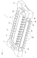
- Fig. 1 is a perspective view of a receptacle connector according to an embodiment of the invention.
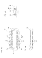
- Fig. 2 is a view showing a structure of the receptacle connector shown in Fig. 1 wherein Fig. 2A is a plan view, Fig. 2B is a front view and Figs. 2C an 2D are sectional views taken along lines X-X and Y-Y in Fig. 2A, respectively.
- a receptacle connector 1 shown in Fig. 1 comprises a housing 10, a receptacle shell 20, receptacle contacts 30 and receptacle earth contacts 40.
- the receptacle connector 1 is a thin small-sized connector having a height of about 1 mm. According to the invention, since it is possible to structure a very thin shell, it is more useful when the invention is applied to such thin small-sized connector.
- the housing 10 is a member made of an insulating resin and having an approximately rectangular parallelepiped shape. As shown in Figs. 1 and 2A, a center of the housing is formed with an approximately rectangular fitting opening 11 into which a plug connector 2 (refer to Fig. 4) is fitted. Accordingly, an end surface (upper surface in Fig. 1) of the housing 10 becomes a ring shape. In addition, a protrusion member 12 protruding upwardly in the fitting opening 11 and having an approximately rectangular parallelepiped shape is formed at a bottom surface of the fitting opening 11. Since a horizontal cross section of the protrusion member 12 is smaller than that of the bottom surface of the fitting opening 11, a ring-shaped fitting recess 13 is formed between the protrusion member 12 and the outer circumference of the housing 10.
- through-holes 14 extending in a horizontal direction and for attaching the receptacle contact 30 and the receptacle earth contact 40 to the housing 10 are formed at attachment positions (refer to Figs. 2A and 2B) of the receptacle contact 30 and the receptacle earth contact 40, respectively.
- Press-fit recesses 16 communicating with the through-holes 15 and extending in a vertical direction are formed at a widthwise center of the long outer circumference 10a.
- a plurality of apertures 17 are formed on upper surfaces of the outer circumferences 10a of the housing 10, respectively.
- the apertures 17 are located to correspond to the attachment positions of the contacts and communicate with the press-fit recesses 16. Accordingly, in Fig. 1, it can be seen top portions of the press-fit part 31 of the receptacle contact 30 and the press-fit part 41 of the receptacle earth contact 40 in the apertures 17 (refer to Figs. 2C and 2D).
- a plurality of recessed portions 18 extending in a vertical direction are formed at positions of the outer circumference of the protrusion member 12 corresponding to the attachment positions of the contacts.
- Leading ends of elastic piece parts 32, 42 (refer to Figs. 2C and 2D) of the receptacle contact 30 and the receptacle earth contact 40 attached to the housing 10 are positioned at the recessed portions 18.
- the receptacle shell 20 made of a conductive material is an integrally molded member having a nearly box shape obtained through punching and bending processes (refer to Fig. 3B).
- the housing 10 is insert-molded such that the receptacle shell 20 is embedded therein. Accordingly, the housing 10 and the receptacle shell 20 are integrally formed.
- the detailed structure of the receptacle shell 20 will be more specifically described later.
- the receptacle contact 30 is a signal terminal fitting made of a conductive material of copper alloy such as brass. As shown in Fig. 2C, the receptacle contact 30 comprises a press-fit part 31 pressed into the housing 10, an elastic piece part 32 having a leading end serving as a terminal to be connected to the plug connector 2 and maintaining the plug connector 2 when the plug connector 2 is fitted, and a lead part 34 having a leading end serving as a terminal to be connected to an attachment surface of a substrate on which the receptacle connector 1 is mounted.
- the press-fit part 31 is a protruding part having an approximately rod shape and pressed into the press-fit recess 16 formed in the outer circumference 10a of the housing. Accordingly, a horizontal cross section of the press-fit part 31 is almost same as that of the press-fit recess 16.
- the press-fir part 31 has a length allowing the leading end thereof not to be protruded from the upper surface of the outer circumference 10a of the housing 10 when the receptacle contact 30 is attached to the housing 10.
- the elastic piece part 32 is a protruding part extending from a root of the press-fit part 31 and having an approximately C-shape.
- the leading end of the elastic piece part is nearly parallel to the press-fit part 31 and has a spring property in a direction toward the press-fit part 31. Accordingly, in case that a force, which acts in a direction away from the press-fit part 31, is applied to the leading end of the elastic piece part 32 from the exterior, the leading end is biased to a direction coming close to the press-fit part 31.
- the plug connector 2 when the plug connector 2 is fitted into the receptacle connector 1, the plug connector 2 contacts the elastic piece part 32, so that the elastic piece part 32 becomes more distant from the press-fit part 31 and maintains the plug connector 2 (refer to Fig. 5).
- the lead part 34 is a part having an approximately rod shape and extending from the root of the press-fit part 31 to a direction opposite to the extending direction of the elastic piece part 32 and almost perpendicular to the press-fit part 31. As a result, the lead part 34 and a portion of the elastic piece part 32 near to the press-fit part 31 are positioned on an approximately straight line.
- the lead part 34 is fixed to the attachment surface of the substrate on which the receptacle connector 1 is mounted, by means of a soldering and the like. Like this, the press-fit part 31, the elastic piece part 32 and the lead part 34 of the receptacle contact 30 are arranged on a nearly same plane.
- the receptacle earth contact 40 is an earth terminal fitting made of a conductive material of copper alloy such as brass. As shown in Fig. 2D, the receptacle earth contact 40 comprises a press-fit part 41 pressed into the housing 10, an elastic piece part 42 having a leading end serving as a terminal to be connected to the plug connector 2 and maintaining the plug connector 2 when the plug connector 2 is fitted, a shell contacting part 43 contacting an outer circumferential surface of the receptacle shell 20 and a lead part 44 having a leading end serving as a terminal to be connected to an attachment surface of a substrate on which the receptacle connector 1 is mounted.
- the shell contacting part 43 is a protruding part having an approximately rod shape and protruding from the lead part 44 in nearly parallel to the press-fit part 41.
- the receptacle earth contact 40 is attached to the housing 10, it is arranged in order of the shell contacting part 43, the press-fit part 41 and the elastic piece part 42 from the outer circumferential surface of the receptacle connector 1 (housing 10) toward the interior, as shown in Fig. 2D.
- the press-fit part 41, the elastic piece part 42, the shell contacting part 43 and the lead part 44 are positioned on a nearly same plane and the press-fit part 41 and the leading end of the elastic piece part 42 and the shell contacting part 43 are protruded in a same direction and almost parallel to each other.
- both the receptacle contact 30 and the receptacle earth contact 40 are plate-shaped members.
- the elastic piece parts 32, 42 are inserted into the through-holes 15 of the housing 10 from the leading ends thereof and the press-fit parts 31, 41 are inserted into the press-fit recesses 16.
- each of the elastic piece parts 32, 42 is positioned in the fitting recess 13 between the outer circumference 10a of the housing 10 and the protrusion member 12 and the lead parts 34, 44 are protruded to the exterior of the housing 10.
- the shell contacting part 43 of the receptacle earth contact 40 contacts the outer circumferential surface of the receptacle shell 20 at the outside of the receptacle connector 1 and thus can be seen from the exterior of the receptacle connector 1.
- the receptacle connector 1 comprises twenty rows of receptacle contacts 30 and four rows of receptacle earth contacts 40. In the mean time, the arrangement and number of the receptacle contacts 30 and the receptacle earth contacts 40 attached to the receptacle connector 1 can be modified.
- the shell contacting part 43 of the receptacle earth contact 40 can be seen from top and side of the exterior of the receptacle connector 1 with eyes, it is possible to easily check the positions of the receptacle earth contacts 40 from the outward shape of the receptacle connector 1. Accordingly, the receptacle contact 30 and the receptacle earth contact 40 of the receptacle connector 1 can be easily identified by a machine vision, for example (i.e., visibility is improved). As a result, in case of an inspection process of the receptacle connector 1, the inspection process has following advantages.
- the process is carried out by an automated process such as machine vision, rather than the eyes. At this time, it is possible to easily specify the position of the receptacle earth contact 40 from the top and the side of the connector.
- FIG. 3 is a view showing a structure of the receptacle shell wherein Fig. 3A is a perspective view of a frame before a press bending process and Fig. 3B is a perspective view of the receptacle shell after the press bending process.
- the frame and the receptacle shell are connected to a pair of carriage support members before and after the press bending process.
- a frame 27 having a shape as shown in Fig. 3A is first prepared through a punching process.
- the frame 27 is a rectangular plate type member and formed with an opening 27a at a center thereof.
- the frame 27 comprises first to fourth shield forming parts 21a to 24a, a first connecting part 25 and a second connecting part 26.
- Both the first and second shield forming parts 21a, 22a are shaped into a rectangular form having a same dimension and arranged to be parallel to each other.
- both the third and fourth shield forming parts 23a, 24a are shaped into a rectangular form having a same dimension and arranged to be parallel to each other.
- lengths of the first and second shield forming parts 21a, 22a are smaller than those of the third and fourth shield forming parts 23a, 24a.
- first connecting part 25 is continuously extended to the widthwise exterior of the first shield forming part 21a. Both lengthwise ends of the first connecting part 25 are connected to one end of the third and fourth shield forming parts 23a, 24a, respectively.
- second connecting part 26 is continuously extended to the widthwise exterior of the second shield forming part 22a. Both ends of the first connecting part 25 are connected to the other end of the third and fourth shield forming parts 23a, 24a, respectively.
- the outer circumference of the frame 27 is formed with the third shield forming part 23a, the fourth shield forming part 24a, the first connecting part 25 and the second connecting part 26.
- the first shield forming part 21a is extended from a widthwise inner end of the first connecting part 25 toward the second connecting part 26 in the opening 27a of the frame 27 and the second shield forming part 22a is extended from a widthwise inner end of the second connecting part 26 toward the first connecting part 25 in the opening 27a of the frame 27.
- the first and second connecting parts 25, 26 are positioned at the outsides of the first and second shield forming parts 21a, 22a and between the third and fourth shield forming parts 23a, 24a.
- a boundary 28a of the first connecting part 25 and the first shield forming part 21a, boundaries 28b, 28c of the first connecting part 25 and the third shield forming part 23a and the fourth shield forming part 24a, a boundary 28d of the second connecting part 26 and the second shield forming part 22a, and boundaries 28c, 28f of the second connecting part 26 and the third shield forming part 23a and the fourth shield forming part 24a are shown with dashed lines.
- the dashed lines are bending lines (referred to as same reference numerals as the boundaries 28a to 28f) in the press bending process.
- the third shield forming part 23a is positioned opposite to the first and second connecting parts 25, 26 with regard to the bending lines 28b, 28e and the fourth shield forming part 24a is positioned opposite to the first and second connecting parts 25, 26 with regard to the bending lines 28c, 28f.
- reinforcing taps 23b, 24b protruding into the opening 27a are formed at places adjacent to both ends of the third and fourth shield forming parts 23a, 24a, respectively.
- the reinforcing taps 23b, 24b are directed towards the respective ends of the first and second shield forming parts 21a, 22a and gaps are formed between leading ends thereof and the respective ends of the first and second shield forming parts 21a, 22a.
- the receptacle shell 20 is prepared, as shown in Fig. 3B.
- the receptacle shell 20 is a nearly box-shaped member surrounded by four shield surfaces.
- the receptacle shell 20 includes a first shield surface 21, a second shield surface 22 opposing to the first shield surface 21, a third shield surface 23 intersecting a plane comprising the first shield surface 21 and a plane comprising the second shield surface 22, a fourth shield surface 24 intersecting the plane comprising the first shield surface 21 and the plane comprising the second shield surface 22 and opposing to the third shield surface 23, the first connecting part 25 connecting the first, third and fourth shield surfaces 21, 23, 24 and the second connecting part connecting the second, third and fourth shield surfaces 22, 23, 24.
- the first to fourth shield forming parts 21a to 24a of the frame 27 before the press bending process are bent with regard to the first and second connecting parts 25, 26 during the press bending process, thereby forming the first to fourth shield surfaces 21 to 24.
- the first to fourth shield surfaces 21 to 24 are approximately perpendicular to the first and second connecting parts 25, 26 and top surfaces thereof (the widthwise inner ends of the first and second shield forming parts 21a, 22a and the widthwise outer ends of the third and fourth shield forming parts 23a, 24a in the frame 27) are located on the nearly same plane.
- the first and second shield forming parts 21a, 22a are positioned between the first and second connecting parts 25, 26. Accordingly, the first and second shield forming parts 21a, 22a are upwardly bent along the bending lines 28a, 28d in the widthwise insides of the first and second connecting parts 25, 26, thereby forming the first and second shield surfaces 21, 22. As a result, the first and second shield surfaces 21, 22 are positioned between the first and second connecting parts 25, 26.
- the third shield forming part 23a is positioned opposite to the first and second connecting parts 26, 26 with regard to the bending lines 28b, 28e and the fourth shield forming part 24a is positioned opposite to the first and second connecting parts 26, 26 with regard to the bending lines 28c, 28f.
- the third shield forming part 23a is upwardly bent along the bending lines 28b, 28e of the both lengthwise ends of the first and second connecting parts 25, 26, thereby forming the third shield surface 23.
- the fourth shiel forming part 24a is upwardly bent along the bending lines 28c, 28f of the both lengthwise ends of the first and second connecting parts 25, 26, thereby forming the fourth shield surface 24.
- both ends of the third shield surface 23 are externally positioned between the first and second shield surfaces 21, 22.
- the third shield surface 23 intersects perpendicularly to both the plane including the first shield surface 21 and the plane including the second shield surface 22.
- both ends of the fourth shield surface 24 are externally positioned between the first and second shield surfaces 21, 22.
- the fourth shield surface 24 intersects perpendicularly to both the plane including the first shield surface 21 and the plane including the second shield surface 22.
- the third and fourth shield surfaces 23, 24 are not nearly collapsed toward the interior even though a force is applied to the third and fourth shields surfaces 23, 24 from the exterior to the interior. Accordingly, it is more preferred that the both ends of the first shield surface 21 and the third and fourth shield surfaces 23, 24 are contacted to each other and both ends of the second shield surface 22 and the third and fourth shield surfaces 23, 24 are contacted to each other under state that the receptacle shell 20 is manufactured.
- the reinforcing taps 23b, 24b formed to the third and fourth shield forming parts 23a, 24a are positioned at lower ends of the receptacle shell 20 under state that the receptacle shell 20 is manufactured.
- the reinforcing taps 23b, 24b are protruded into a direction that the receptacle connector 1 having the receptacle shell 20 and the housing 10 insert-molded to embed the shell therein intersects the attachment surface of the substrate on which the connector is mounted.
- the reinforcing taps 23b, 24b is fixed to the attachment surface by means of a soldering when the receptacle connector 1 is mounted on the attachment surface of the substrate. Accordingly, in this case, a release strength of the receptacle connector 1 from the attachment surface of the substrate is improved, compared to the case that the receptacle connector 1 is fixed to the attachment surface of the substrate through the solderings of the lead part 34 of the receptacle contact 30 and the lead part 44 of the receptacle earth contact 40 only.
- the reinforcing taps 23b, 24b is used for the fixing to the attachment surface of the substrate and connected and thus earthed to an earth part (ground pattern) on the substrate. Accordingly, the receptacle shell 20 is earthed via the reinforcing taps 23b, 24b as well as the shell contacting part 43 of the receptacle earth contact 40.
- the plug connector 2 fitted to the receptacle connector 1 comprises a housing 50 and a plug connector 60, as shown in Fig. 4.
- Fig. 4 is a view showing a structure of a plug connector to be fitted to the receptacle connector shown in FIG. 1 wherein Fig. 4A is a plan view, Fig. 4B is a front view and Fig. 4C is a sectional view taken along line X-X in FIG. 4A.
- the housing 50 is a rectangular parallelepiped member made of an insulating resin and formed with a fitting opening 51 at a center thereof into which the protrusion member 12 of the receptacle connector 1 is inserted when it is fitted to the receptacle connector 1. Accordingly, an end surface of the housing 50 (for example, an upper surface in Fig. 4C) becomes a ring shape.
- An outward shape of the housing 50 is nearly same as that of the fitting recess 13 formed between the outer circumference of the housing 10 and the protrusion member 12 of the receptacle connector 1.
- a dimension of the fitting opening 51 is nearly same as the horizontal cross section of the protrusion member 12. Accordingly, the ring-shaped outer circumference of the housing 50 of the plug connector 2 can be fitted into the fitting recess 13 of the receptacle connector 1.
- press-fit recesses 55 for attaching the plug contact 60 to the housing 50 are respectively formed at attachment positions of the plug contact 60, as shown in Fig. 4C.
- the plug contact 60 comprises a press-fit part 61 pressed into the housing 50, a contacting part 62 contacting the elastic piece parts 32, 42 and serving as a terminal to be connected to the receptacle connector 1 when the plug connector is fitted to the receptacle connector 1, and a lead part 64 having a leading end serving as a terminal to be connected to an attachment surface of a substrate on which the plug connector 2 is mounted.
- the plug contact 60 has an approximately L-shape.
- a part bent perpendicularly to the lead part 64 having a nearly rod shape becomes the contacting part 62 and a part bent from the leading end of the contacting part 62 toward the lead par 64 into an U-shape becomes the press-fit part 61.
- the press-fit part 61, the contacting part 62 and the lead part 64 of the plug contact 60 are arranged on an almost same plane.
- the plug connector 2 12 rows of the plug contacts 50 are attached to each of the long outer circumferences 50a of the housing 50. Accordingly, the plug connector 2 comprises 24 rows of the plug contacts 60.
- the plug contacts 60 having same shapes of the signal terminal fitting to be connected to the receptacle contact 30 and the earth terminal fitting to be connected to the receptacle earth contact 40 are used for the plug connector 2.
- FIG. 5 shows a fitted state of a receptacle connector and a plug connector, wherein Fig. 5A shows the fitted state in an attachment position of the receptacle contact and Fig. 5B shows the fitted state in an attachment position of the receptacle earth contact.
- the lead part 34 of the receptacle contact 30 of the receptacle connector 1 is electrically connected to the lead part 64 of the plug contact 60 of the plug connector 2.
- the lead part 44 of the receptacle earth contact 40 of the receptacle connector 1 is electrically connected to the lead part 64 of the plug contact 60 of the plug connector 2. Since the shell contacting part 43 of the receptacle earth contact 40 is contacted to the receptacle shell 20, the receptacle shell 20 is also earthed in case that the lead part 44 and the lead part 64 of the plug contact 60 connected to the receptacle earth contact 40 are grounded.
- Fig. 6 is a view showing each process when a receptacle connector is manufactured.
- the frame having the first shield forming parts 21a to 24a, the first connecting part 25 and the second connecting part 26 are prepared through a punching process.
- the frame 27 is arranged between a pair of carriage support members 80 opposite to each other and connected to the support members 80 via a pair of connecting parts 80a extending from both ends of the frame 27 to the outside.
- apertures 80b are formed in the carriage support members 80 into which protrusions (not shown) of a carrying apparatus are closely fitted.
- the pair of carriage support members 80 support the one frame 27 only.
- the pair of carriage support members 80 support a plurality of frames 27 arranged at an interval in an extending direction of the members (vertical direction in Fig. 6).
- the housing 10 is insert-molded so that the receptacle 20 is embedded therein.
- the receptacle contacts 30 and the receptacle earth contacts 40 are attached to the housing 10.
- the receptacle connector 1 with being connected to the carriage support members 80 is prepared through the processes, the receptacle connector is cut along the boundaries of the first and second connecting parts 25, 26 of the receptacle shell 20 and the connecting parts 80a in a cutting process, as shown in Fig. 6E, so that the receptacle connector 1 is removed from the pair of carriage support members 80.
- the receptacle connector 1 of this embodiment comprises the receptacle shell 20 and the receptacle earth contact 40 having the shell contacting part 43 contacted to the receptacle shell 20 and the receptacle shell 20 is earthed. Owing to this, even when the receptacle connector 1 is inserted/disconnected into/from the plug connector 2, it is maintained the contacted state between the receptacle earth contact 40 and the receptacle shell 20. Accordingly, it is suppressed a damage of the receptacle earth contact 40 when the receptacle connector 1 is inserted/disconnected into/from the plug connector 2. As a result, a reliability of the receptacle earth contact 40 is improved. In addition, since it is possible to stably secure an earth route irrespective of the insertion/disconnection of the connector, a reliability of the receptacle connector 1 is improved.
- the shell contacting point 43 is not contacted to the receptacle shell 20
- the receptacle contact 30 and the receptacle earth contact 40 of the receptacle connector 1 can be easily identified by a machine vision, for example, an inspection process of the receptacle connector 1 is simplified.
- shapes of the receptacle contact 30 and the receptacle earth contact 40 are almost same except whether or not there is the shell contacting part 43, it is possible to assemble the receptacle contact 30 and the receptacle earth contact 40 at any positions when assembling them to the receptacle connector 1.
- the press-fit part 41, the leading end of the elastic piece part 42 and the shell contacting part 43 of the receptacle earth contact 40 are the protrusions protruding in a same direction. Accordingly, it is possible to electrically connect the plug connector 2 and the substrate on which the receptacle connector 1 is mounted and to easily manufacture the receptacle earth contact 40 contacting the receptacle shell 20.
- the protruding parts 23b, 24b are formed at the third and fourth shield surfaces 23, 24 of the receptacle shell 20, in case that the receptacle connector 1 is mounted on the attachment surface of the substrate, it is possible to fix the receptacle connector 1 to the attachment surface by means of for example, a soldering, using the protruding parts 23b, 24b. Accordingly, when the plug connector 2 fitted to the receptacle connector 1 is disconnected, it is suppressed the release of the receptacle connector 1 from the substrate. In addition, since it is possible to increase the earthed part of the receptacle shell 20 by grounding the receptacle shell 20 via the protruding parts 23b, 24b, the receptacle shell 20 can be reliably earthed.
- the protruding parts 23b, 24b are formed at the third and fourth shield surfaces 23, 24 of the receptacle shell 20 in the above embodiment, the protruding parts 23b, 24b may be omitted.
- the same effects as the above embodiment can be obtained if any one of the first to fourth shield surfaces 21 to 24 is provided with the protruding parts.
- the press-fit part 41, the leading end of the elastic piece part 42 and the shell contacting part 43 of the receptacle earth contact 40 are the protrusions protruding in a same direction in the above embodiment, the shape of the receptacle earth contact 40 may be changed.
Abstract
Description
- The present invention relates to an electric connector used to electrically connect a plurality of substrates and the like.
- In general, an electric device such as cellular phone has a plurality of substrates therein. It is necessary to electrically connect the substrates each other so as to transmit and receive a variety of signals between the substrates. When electrically connecting the substrates, it is often used a board-to-board type of connector assembly consisting of a plug connector and a receptacle connector fitted to each other, for example. In other words, in this case, when a substrate having a plug connector attached thereto and a substrate having a receptacle connector attached thereto are connected, the plug connector and the receptacle connector are fitted to each other, so that the substrates are electrically connected.
- In case that noise is introduced into the connector from an exterior, it may cause a malfunction thereof. In addition, in case that the noise is radiated from the connector to the exterior, it may cause a malfunction of a peripheral device. Accordingly, it is preferred to use a connector having a metal shield attached thereto as the connector used for the electrical device such as cellular phone.
- It has been developed a variety of connectors having a metal shell attached thereto. A Japanese Patent Unexamined Publication No. Hei 10-335000 discloses a connector assembly consisting of a plug connector having a ground shell and a receptacle connector having a terminal including a second contact piece. When the plug connector and the receptacle connector are fitted to each other, the second contact piece is engaged to an outer wall of the ground shell. Accordingly, in case that the terminal is grounded, it is possible to obtain a shield effect by the ground shell because the ground shell is grounded via the second contact piece.
- However, according to the connector assembly disclosed in the Japanese patent, the plug connector has the ground shell and the receptacle connector has the terminal including the second contact piece for grounding the ground shell. Accordingly, whenever the plug connector and the receptacle connector are inserted/disconnected, the ground shell is contacted, thereby applying a force to the second contact piece. Therefore, the terminal including the second contact piece is liable to be damaged.
- In addition, an insulating housing is arranged to the outside of the second contact piece of the receptacle connector. Accordingly, it is impossible to see the second contact piece with eyes from the exterior of the receptacle connector. As a result, it is difficult to identify a plurality of receptacle connectors having the second contact pieces assembled at positions different from each other.
- Further, the plug connector and the receptacle connector are fitted to each other, so that the second contact piece and the ground shell are contacted to each other in the receptacle connector. Accordingly, even when the second contact piece and the ground shell are under non-contact state, it is difficult to repair the non-contact state from the exterior.
- An object of the invention is to provide a high reliable earth terminal fitting and an electric connector having the same.
- Another object of the invention is to provide an electric connector capable of being easily identified.
- According to an aspect of the invention, there is provided an earth terminal fitting assembled to an electric connector having a frame type shell for an electric connector and a housing insert-molded so that the electric connector shell is embedded therein, and having an end serving as a terminal to be connected to an attachment surface of a substrate on which the electric connector is mounted and the other end serving as a terminal to be connected to the other connector, the terminal fitting comprising a press-fit part pressed into the housing with the terminal fitting being assembled to the electric connector; a lead part connected to the press-fit part and having a leading end serving as a terminal to be connected to an attachment surface of a substrate on which the electric connector is mounted; and a shell contacting part contacted to the electric connector shell with the terminal fitting being assembled to the electric connector.
- According to the invention, it is possible to ground the electric connector shell assembled to the electric connector by means of the earth terminal fitting assembled to the same electric connector and contacting the shell. As a result, even when the electric connector is inserted/disconnected into/from the other connector, the contacted state between the earth terminal fitting and the shell is maintained. Accordingly, it is possible to prevent the earth terminal fitting from being damaged as the electric connector is inserted/disconnected into/from the other connector. Therefore, a reliability of the earth terminal fitting is improved. In addition, since it is possible to stably secure an earth route irrespective of the insertion/disconnection of the connectors, a reliability of the electric connector having the earth terminal fitting is also improved.
- According to an embodiment of the invention, the earth terminal fitting may further comprise an elastic piece part connected to a side opposite to the press-fit part and the lead part, having a leading end serving as the terminal to be connected to the other connector and maintaining the other connector when the other connector is fitted. All the press-fit part, the elastic piece part and the shell contacting part may be protrusions protruding in a same direction.
- According to the invention, it is possible to electrically connect the other connector and the substrate having the electric connector mounted thereon and to easily manufacture the earth terminal fitting contacting the shell.
- According to another aspect of the invention, there is provided an electric connector comprising a frame type shell for an electric connector, a housing insert-molded so that the electric connector shell is embedded therein and at least one of the above mentioned earth terminal fittings.
- According to the invention, it is possible to obtain an electric connector comprising the electric connector shell and the earth terminal fitting having the shell contacting part contacted to the shell wherein the electric connector shell is earthed. As a result, even when the electric connector is inserted/disconnected into/from the other connector, the contacted state between the earth terminal fitting and the shell is maintained. Accordingly, it is possible to prevent the earth terminal fitting from being damaged as the electric connector is inserted/disconnected into/from the other connector. Therefore, a reliability of the earth terminal fitting is improved. In addition, it is possible to stably secure an earth route irrespective of the insertion/disconnection of the connectors.
- According to an embodiment of the invention, the electric connector shell may have a protrusion protruding in a direction intersecting the attachment surface of the substrate on which the electric connector is mounted.
- According to the above invention, in case that the electric connector is mounted on the attachment surface of the substrate, it is possible to fix the electric connector to the attachment surface by means of a soldering and the like. Accordingly, a release strength of the electric connector from the substrate is improved and it is suppressed the release of the electric connector from the substrate when the other connector fitted into the electric connector is disconnected. In addition, since it is possible to increase the earthed part of the shell by grounding the shell via the protrusion, the shell can be reliably earthed.
- According to the invention, there is provided an electric connector comprising a frame type shell for an electric connector; a housing insert-molded so that the shell is embedded therein; an earth terminal fitting having a first press-fit part pressed into the housing, a first lead part connected to the first press-fit part and having a leading end serving as a terminal to be connected to an attachment surface of a substrate on which the electric connector is mounted, and a shell contacting part contacted to the electric connector shell and capable of being visible from an exterior of the electric connector; and a signal terminal fitting having a second press-fit part pressed into the housing and a second lead part connected to the second press-fit part and having a leading end serving as a terminal to be connected to the attachment surface of the substrate on which the electric connector is mounted, the signal terminal fitting having no shell contacting part.
- According to the invention, since the shell contacting part of the earth terminal fitting can be seen from the exterior of the electric connector with eyes, it is possible to easily check a position of the earth terminal fittin inserted into the electric connector. Accordingly, even when there are a plurality of electric connectors having the earth terminal fittings assembled at positions different from each other, it is possible to easily identify the electric connectors. In addition, an earthed part of the electric connector becomes clear in manufacturing process, keeping process and a process of a set maker. Further, in case that there is a problem at the shell contacting point (for example, the shell contacting part is not contacted to the shell), it is possible to easily perform a repair operation such as fixing operation with a soldering from the exterior of the electric connector. Additionally, since the earth terminal fitting and the signal terminal fitting of the electric connector can be easily identified by a machine vision, for example, an inspection process of the electric connector is simplified. In addition, since shapes of the earth terminal fitting and the signal terminal fitting are almost same except whether or not there is the shell contacting part, it is possible to assemble the earth terminal fitting and the signal terminal fitting at any positions when assembling them to the electric connector.
- According to an embodiment of the invention, the earth terminal fitting may further comprise a first elastic piece part connected to a side opposite to the first press-fit part and the first lead part, having a leading end serving as the terminal to be connected to the other connector and maintaining the other connector when the other connector is fitted, and all the first press-fit part, the first elastic piece part and the shell contacting part may be protrusions protruding in a same direction.
- According to the invention, it is possible to electrically connect the other connector and the substrate having the electric connector mounted thereon and to easily manufacture the earth terminal fitting contacting the shell.
- According to an embodiment of the invention, the electric connector shell may have a protrusion protruding in a direction intersecting the attachment surface of the substrate on which the electric connector is mounted.
- According to the invention, in case that the electric connector is mounted on the attachment surface of the substrate, it is possible to fix the electric connector to the attachment surface by means of a soldering and the like. Accordingly, a release strength of the electric connector from the substrate is improved and it is suppressed the release of the electric connector from the substrate when the other connector fitted into the electric connector is disconnected. In addition, since it is possible to increase the earthed part of the shell by grounding the shell via the protrusion, the shell can be reliably earthed.
- Other and further objects, features and advantages of the invention will appear more fully from the following description taken in connection with the accompanying drawings, in which:
- FIG. 1 is a perspective view of a receptacle connector according to an embodiment of the invention;
- FIG. 2 is a view showing a structure of the receptacle connector shown in FIG. 1 wherein FIG. 2A is a plan view, FIG. 2B is a front view and FIGS. 2C and 2D are sectional views taken along lines X-X and Y-Y in FIG. 2A, respectively;
- FIG. 3 is a view showing a structure of a receptacle shell wherein FIG. 3A is a perspective view of a frame before a press bending process and FIG. 3B is a perspective view of the receptacle shell after the press bending process;
- FIG. 4 is a view showing a structure of a plug connector to be fitted to the receptacle connector shown in FIG. 1 wherein FIG. 4A is a plan view, FIG. 4B is a front view and FIG. 4C is a sectional view taken along line X-X in FIG. 4A;
- FIG. 5 is a view showing a fitted state of a receptacle connector and a plug connector; and
- FIG. 6 is a view showing each process when a receptacle connector is manufactured.
- Hereinafter, preferred embodiment of the present invention will be described.
- Fig. 1 is a perspective view of a receptacle connector according to an embodiment of the invention. Fig. 2 is a view showing a structure of the receptacle connector shown in Fig. 1 wherein Fig. 2A is a plan view, Fig. 2B is a front view and Figs. 2C an 2D are sectional views taken along lines X-X and Y-Y in Fig. 2A, respectively.
- A
receptacle connector 1 shown in Fig. 1 comprises ahousing 10, areceptacle shell 20,receptacle contacts 30 andreceptacle earth contacts 40. Thereceptacle connector 1 is a thin small-sized connector having a height of about 1 mm. According to the invention, since it is possible to structure a very thin shell, it is more useful when the invention is applied to such thin small-sized connector. - The
housing 10 is a member made of an insulating resin and having an approximately rectangular parallelepiped shape. As shown in Figs. 1 and 2A, a center of the housing is formed with an approximately rectangularfitting opening 11 into which a plug connector 2 (refer to Fig. 4) is fitted. Accordingly, an end surface (upper surface in Fig. 1) of thehousing 10 becomes a ring shape. In addition, aprotrusion member 12 protruding upwardly in thefitting opening 11 and having an approximately rectangular parallelepiped shape is formed at a bottom surface of thefitting opening 11. Since a horizontal cross section of theprotrusion member 12 is smaller than that of the bottom surface of thefitting opening 11, a ring-shapedfitting recess 13 is formed between theprotrusion member 12 and the outer circumference of thehousing 10. - In addition, as shown in Figs. 2C and 2D, in lower ends of a pair of long
outer circumferences 10a of thehousing 10, through-holes 14 extending in a horizontal direction and for attaching thereceptacle contact 30 and thereceptacle earth contact 40 to thehousing 10 are formed at attachment positions (refer to Figs. 2A and 2B) of thereceptacle contact 30 and thereceptacle earth contact 40, respectively. Press-fit recesses 16 communicating with the through-holes 15 and extending in a vertical direction are formed at a widthwise center of the longouter circumference 10a. - Additionally, a plurality of
apertures 17 arranged at an equal interval, are formed on upper surfaces of theouter circumferences 10a of thehousing 10, respectively. Theapertures 17 are located to correspond to the attachment positions of the contacts and communicate with the press-fit recesses 16. Accordingly, in Fig. 1, it can be seen top portions of the press-fit part 31 of thereceptacle contact 30 and the press-fit part 41 of thereceptacle earth contact 40 in the apertures 17 (refer to Figs. 2C and 2D). - A plurality of recessed
portions 18 extending in a vertical direction are formed at positions of the outer circumference of theprotrusion member 12 corresponding to the attachment positions of the contacts. Leading ends ofelastic piece parts 32, 42 (refer to Figs. 2C and 2D) of thereceptacle contact 30 and thereceptacle earth contact 40 attached to thehousing 10 are positioned at the recessedportions 18. - The
receptacle shell 20 made of a conductive material is an integrally molded member having a nearly box shape obtained through punching and bending processes (refer to Fig. 3B). In the mean time, when molding thehousing 10, thehousing 10 is insert-molded such that thereceptacle shell 20 is embedded therein. Accordingly, thehousing 10 and thereceptacle shell 20 are integrally formed. The detailed structure of thereceptacle shell 20 will be more specifically described later. - The
receptacle contact 30 is a signal terminal fitting made of a conductive material of copper alloy such as brass. As shown in Fig. 2C, thereceptacle contact 30 comprises a press-fit part 31 pressed into thehousing 10, anelastic piece part 32 having a leading end serving as a terminal to be connected to theplug connector 2 and maintaining theplug connector 2 when theplug connector 2 is fitted, and alead part 34 having a leading end serving as a terminal to be connected to an attachment surface of a substrate on which thereceptacle connector 1 is mounted. - The press-
fit part 31 is a protruding part having an approximately rod shape and pressed into the press-fit recess 16 formed in theouter circumference 10a of the housing. Accordingly, a horizontal cross section of the press-fit part 31 is almost same as that of the press-fit recess 16. In addition, the press-fir part 31 has a length allowing the leading end thereof not to be protruded from the upper surface of theouter circumference 10a of thehousing 10 when thereceptacle contact 30 is attached to thehousing 10. - The
elastic piece part 32 is a protruding part extending from a root of the press-fit part 31 and having an approximately C-shape. The leading end of the elastic piece part is nearly parallel to the press-fit part 31 and has a spring property in a direction toward the press-fit part 31. Accordingly, in case that a force, which acts in a direction away from the press-fit part 31, is applied to the leading end of theelastic piece part 32 from the exterior, the leading end is biased to a direction coming close to the press-fit part 31. In other words, when theplug connector 2 is fitted into thereceptacle connector 1, theplug connector 2 contacts theelastic piece part 32, so that theelastic piece part 32 becomes more distant from the press-fit part 31 and maintains the plug connector 2 (refer to Fig. 5). - The
lead part 34 is a part having an approximately rod shape and extending from the root of the press-fit part 31 to a direction opposite to the extending direction of theelastic piece part 32 and almost perpendicular to the press-fit part 31. As a result, thelead part 34 and a portion of theelastic piece part 32 near to the press-fit part 31 are positioned on an approximately straight line. In addition, thelead part 34 is fixed to the attachment surface of the substrate on which thereceptacle connector 1 is mounted, by means of a soldering and the like. Like this, the press-fit part 31, theelastic piece part 32 and thelead part 34 of thereceptacle contact 30 are arranged on a nearly same plane. - The
receptacle earth contact 40 is an earth terminal fitting made of a conductive material of copper alloy such as brass. As shown in Fig. 2D, thereceptacle earth contact 40 comprises a press-fit part 41 pressed into thehousing 10, anelastic piece part 42 having a leading end serving as a terminal to be connected to theplug connector 2 and maintaining theplug connector 2 when theplug connector 2 is fitted, ashell contacting part 43 contacting an outer circumferential surface of thereceptacle shell 20 and alead part 44 having a leading end serving as a terminal to be connected to an attachment surface of a substrate on which thereceptacle connector 1 is mounted. - Shapes of the press-
fit part 41, theelastic piece part 42 and thelead part 44 of thereceptacle earth contact 40 are almost same as those of the press-fit part 31, theelastic piece part 32 and thelead part 34 of thereceptacle contact 30. Therefore, detailed descriptions thereof are omitted. In addition, theshell contacting part 43 is a protruding part having an approximately rod shape and protruding from thelead part 44 in nearly parallel to the press-fit part 41. Accordingly, in case that thereceptacle earth contact 40 is attached to thehousing 10, it is arranged in order of theshell contacting part 43, the press-fit part 41 and theelastic piece part 42 from the outer circumferential surface of the receptacle connector 1 (housing 10) toward the interior, as shown in Fig. 2D. In the mean time, the press-fit part 41, theelastic piece part 42, theshell contacting part 43 and thelead part 44 are positioned on a nearly same plane and the press-fit part 41 and the leading end of theelastic piece part 42 and theshell contacting part 43 are protruded in a same direction and almost parallel to each other. - In addition, both the
receptacle contact 30 and thereceptacle earth contact 40 are plate-shaped members. When they are attached to thehousing 10, theelastic piece parts holes 15 of thehousing 10 from the leading ends thereof and the press-fit parts elastic piece parts fitting recess 13 between theouter circumference 10a of thehousing 10 and theprotrusion member 12 and thelead parts housing 10. In addition, as shown in Figs. 1 and 2D, theshell contacting part 43 of thereceptacle earth contact 40 contacts the outer circumferential surface of thereceptacle shell 20 at the outside of thereceptacle connector 1 and thus can be seen from the exterior of thereceptacle connector 1. - Like this, with the
receptacle connector 1, ten rows ofreceptacle contacts 30 are attached to each of the longouter circumferences 10a of thehousing 10 and two rows ofreceptacle earth contacts 40 are attached while interposing the receptacle contacts between them. Accordingly, thereceptacle connector 1 comprises twenty rows ofreceptacle contacts 30 and four rows ofreceptacle earth contacts 40. In the mean time, the arrangement and number of thereceptacle contacts 30 and thereceptacle earth contacts 40 attached to thereceptacle connector 1 can be modified. Accordingly, it is possible to arbitrarily change a position of thereceptacle earth contact 40 for grounding thereceptacle shell 20 by changing the attachment positions of thereceptacle contacts 30 and thereceptacle earth contacts 40 to thereceptacle connector 1. - Since the
shell contacting part 43 of thereceptacle earth contact 40 can be seen from top and side of the exterior of thereceptacle connector 1 with eyes, it is possible to easily check the positions of thereceptacle earth contacts 40 from the outward shape of thereceptacle connector 1. Accordingly, thereceptacle contact 30 and thereceptacle earth contact 40 of thereceptacle connector 1 can be easily identified by a machine vision, for example (i.e., visibility is improved). As a result, in case of an inspection process of thereceptacle connector 1, the inspection process has following advantages. - In an inspection process for checking that the
receptacle contact 30 and thereceptacle earth contact 40 are not improperly attached to thereceptacle connector 1, the process is carried out by an automated process such as machine vision, rather than the eyes. At this time, it is possible to easily specify the position of thereceptacle earth contact 40 from the top and the side of the connector. - Hereinafter, detailed structures of the receptacle shell are described with reference to Fig. 3. Fig. 3 is a view showing a structure of the receptacle shell wherein Fig. 3A is a perspective view of a frame before a press bending process and Fig. 3B is a perspective view of the receptacle shell after the press bending process. In fact, the frame and the receptacle shell are connected to a pair of carriage support members before and after the press bending process.
- In case of manufacturing the
receptacle shell 20, aframe 27 having a shape as shown in Fig. 3A is first prepared through a punching process. Theframe 27 is a rectangular plate type member and formed with anopening 27a at a center thereof. Theframe 27 comprises first to fourthshield forming parts 21a to 24a, a first connectingpart 25 and a second connectingpart 26. - Both the first and second
shield forming parts shield forming parts shield forming parts shield forming parts - In addition, the first connecting
part 25 is continuously extended to the widthwise exterior of the firstshield forming part 21a. Both lengthwise ends of the first connectingpart 25 are connected to one end of the third and fourthshield forming parts part 26 is continuously extended to the widthwise exterior of the secondshield forming part 22a. Both ends of the first connectingpart 25 are connected to the other end of the third and fourthshield forming parts - Accordingly, the outer circumference of the
frame 27 is formed with the thirdshield forming part 23a, the fourthshield forming part 24a, the first connectingpart 25 and the second connectingpart 26. The firstshield forming part 21a is extended from a widthwise inner end of the first connectingpart 25 toward the second connectingpart 26 in theopening 27a of theframe 27 and the secondshield forming part 22a is extended from a widthwise inner end of the second connectingpart 26 toward the first connectingpart 25 in theopening 27a of theframe 27. In other words, the first and second connectingparts shield forming parts shield forming parts - In Fig. 3A, a
boundary 28a of the first connectingpart 25 and the firstshield forming part 21a,boundaries part 25 and the thirdshield forming part 23a and the fourthshield forming part 24a, aboundary 28d of the second connectingpart 26 and the secondshield forming part 22a, andboundaries part 26 and the thirdshield forming part 23a and the fourthshield forming part 24a are shown with dashed lines. The dashed lines are bending lines (referred to as same reference numerals as theboundaries 28a to 28f) in the press bending process. - The third
shield forming part 23a is positioned opposite to the first and second connectingparts bending lines shield forming part 24a is positioned opposite to the first and second connectingparts bending lines - In addition, two reinforcing
taps opening 27a are formed at places adjacent to both ends of the third and fourthshield forming parts shield forming parts shield forming parts - In the press bending process, when the
frame 27 is bent into a same direction along thebending lines 28a to 28f (upward direction in Fig. 3), thereceptacle shell 20 is prepared, as shown in Fig. 3B. Thereceptacle shell 20 is a nearly box-shaped member surrounded by four shield surfaces. - The
receptacle shell 20 includes afirst shield surface 21, asecond shield surface 22 opposing to thefirst shield surface 21, athird shield surface 23 intersecting a plane comprising thefirst shield surface 21 and a plane comprising thesecond shield surface 22, afourth shield surface 24 intersecting the plane comprising thefirst shield surface 21 and the plane comprising thesecond shield surface 22 and opposing to thethird shield surface 23, the first connectingpart 25 connecting the first, third and fourth shield surfaces 21, 23, 24 and the second connecting part connecting the second, third and fourth shield surfaces 22, 23, 24. The first to fourthshield forming parts 21a to 24a of theframe 27 before the press bending process are bent with regard to the first and second connectingparts - The first to fourth shield surfaces 21 to 24 are approximately perpendicular to the first and second connecting
parts shield forming parts shield forming parts - As described above, with the
frame 27, the first and secondshield forming parts parts shield forming parts bending lines parts parts - In the mean time, with the
frame 27, the thirdshield forming part 23a is positioned opposite to the first and second connectingparts bending lines shield forming part 24a is positioned opposite to the first and second connectingparts bending lines shield forming part 23a is upwardly bent along the bendinglines parts third shield surface 23. Likewise, the fourthshiel forming part 24a is upwardly bent along thebending lines parts fourth shield surface 24. - As a result, both ends of the
third shield surface 23 are externally positioned between the first and second shield surfaces 21, 22. In other words, thethird shield surface 23 intersects perpendicularly to both the plane including thefirst shield surface 21 and the plane including thesecond shield surface 22. Likewise, both ends of thefourth shield surface 24 are externally positioned between the first and second shield surfaces 21, 22. In other words, thefourth shield surface 24 intersects perpendicularly to both the plane including thefirst shield surface 21 and the plane including thesecond shield surface 22. - In addition, somewhat gaps are formed between the both ends of the
first shield surface 21 and the third and fourth shield surfaces 23, 24 and between the both ends of thesecond shield surface 22 and the third and fourth shield surfaces 23, 24. Accordingly, in case that a force is applied to the third and fourth shields surfaces 23, 24 from the exterior to the interior, even though the third and fourth shields surfaces 23, 24 are collapsed to the interior, since they contact the both ends of the first and second shield surfaces 21, 21, the third and fourth shields surfaces 23, 24 can be collapsed toward the interior only to the extent of the gaps. - In the mean time, under state that the
receptacle shell 20 is manufactured, in case that there are no gaps between the both ends of thefirst shield surface 21 and the third and fourth shield surfaces 23, 24 and between the both ends of thesecond shield surface 22 and the third and fourth shield surfaces 23, 24, the third and fourth shield surfaces 23, 24 are not nearly collapsed toward the interior even though a force is applied to the third and fourth shields surfaces 23, 24 from the exterior to the interior. Accordingly, it is more preferred that the both ends of thefirst shield surface 21 and the third and fourth shield surfaces 23, 24 are contacted to each other and both ends of thesecond shield surface 22 and the third and fourth shield surfaces 23, 24 are contacted to each other under state that thereceptacle shell 20 is manufactured. - In addition, the reinforcing
taps shield forming parts receptacle shell 20 under state that thereceptacle shell 20 is manufactured. In other words, the reinforcingtaps receptacle connector 1 having thereceptacle shell 20 and thehousing 10 insert-molded to embed the shell therein intersects the attachment surface of the substrate on which the connector is mounted. - The reinforcing taps 23b, 24b is fixed to the attachment surface by means of a soldering when the
receptacle connector 1 is mounted on the attachment surface of the substrate. Accordingly, in this case, a release strength of thereceptacle connector 1 from the attachment surface of the substrate is improved, compared to the case that thereceptacle connector 1 is fixed to the attachment surface of the substrate through the solderings of thelead part 34 of thereceptacle contact 30 and thelead part 44 of thereceptacle earth contact 40 only. - In addition, according to this embodiment, the reinforcing
taps receptacle shell 20 is earthed via the reinforcingtaps shell contacting part 43 of thereceptacle earth contact 40. - In the mean time, the
plug connector 2 fitted to thereceptacle connector 1 comprises ahousing 50 and aplug connector 60, as shown in Fig. 4. Meanwhile, Fig. 4 is a view showing a structure of a plug connector to be fitted to the receptacle connector shown in FIG. 1 wherein Fig. 4A is a plan view, Fig. 4B is a front view and Fig. 4C is a sectional view taken along line X-X in FIG. 4A. - The
housing 50 is a rectangular parallelepiped member made of an insulating resin and formed with afitting opening 51 at a center thereof into which theprotrusion member 12 of thereceptacle connector 1 is inserted when it is fitted to thereceptacle connector 1. Accordingly, an end surface of the housing 50 (for example, an upper surface in Fig. 4C) becomes a ring shape. An outward shape of thehousing 50 is nearly same as that of thefitting recess 13 formed between the outer circumference of thehousing 10 and theprotrusion member 12 of thereceptacle connector 1. In addition, a dimension of thefitting opening 51 is nearly same as the horizontal cross section of theprotrusion member 12. Accordingly, the ring-shaped outer circumference of thehousing 50 of theplug connector 2 can be fitted into thefitting recess 13 of thereceptacle connector 1. - In ends of a pair of
outer circumferences 50a of the housing 50 (in Fig. 4A, ends in front of sheet), press-fit recesses 55 for attaching theplug contact 60 to thehousing 50 are respectively formed at attachment positions of theplug contact 60, as shown in Fig. 4C. - As shown in Fig. 4C, the
plug contact 60 comprises a press-fit part 61 pressed into thehousing 50, a contactingpart 62 contacting theelastic piece parts receptacle connector 1 when the plug connector is fitted to thereceptacle connector 1, and alead part 64 having a leading end serving as a terminal to be connected to an attachment surface of a substrate on which theplug connector 2 is mounted. - The
plug contact 60 has an approximately L-shape. In other words, a part bent perpendicularly to thelead part 64 having a nearly rod shape becomes the contactingpart 62 and a part bent from the leading end of the contactingpart 62 toward thelead par 64 into an U-shape becomes the press-fit part 61. Like this, the press-fit part 61, the contactingpart 62 and thelead part 64 of theplug contact 60 are arranged on an almost same plane. - In the
plug connector plug contacts 50 are attached to each of the longouter circumferences 50a of thehousing 50. Accordingly, theplug connector 2 comprises 24 rows of theplug contacts 60. - In this embodiment, while the shapes of the
receptacle contact 30 serving as the signal terminal fitting and thereceptacle earth contact 40 serving as the earth terminal fitting are different from each other in thereceptacle connector 1, theplug contacts 60 having same shapes of the signal terminal fitting to be connected to thereceptacle contact 30 and the earth terminal fitting to be connected to thereceptacle earth contact 40 are used for theplug connector 2. - Then, it will be described a fitted state of the
receptacle connector 1 and theplug connector 2 included in a board-to-board type of connector assembly with reference to Fig. 5. Fig. 5 shows a fitted state of a receptacle connector and a plug connector, wherein Fig. 5A shows the fitted state in an attachment position of the receptacle contact and Fig. 5B shows the fitted state in an attachment position of the receptacle earth contact. - When the ring-shaped outer circumference of the
housing 50 of theplug connector 2 is inserted into thefitting recess 13 of thehousing 10 of thereceptacle connector 1, theelastic piece parts receptacle contact 30 and thereceptacle earth contact 40 of thereceptacle connector 1 are fitted while contacting the contactingpart 62 of theplug connector 60 of theplug connector 2. When theplug connector 2 is properly fitted into thereceptacle connector 1, most of theplug connector 2 is received in thereceptacle shell 20 of thereceptacle connector 1. - Accordingly, as shown in Fig. 5A, the
lead part 34 of thereceptacle contact 30 of thereceptacle connector 1 is electrically connected to thelead part 64 of theplug contact 60 of theplug connector 2. In the mean time, as shown in Fig. 5B, thelead part 44 of thereceptacle earth contact 40 of thereceptacle connector 1 is electrically connected to thelead part 64 of theplug contact 60 of theplug connector 2. Since theshell contacting part 43 of thereceptacle earth contact 40 is contacted to thereceptacle shell 20, thereceptacle shell 20 is also earthed in case that thelead part 44 and thelead part 64 of theplug contact 60 connected to thereceptacle earth contact 40 are grounded. - Then, a method of manufacturing the
receptacle connector 1 will be described with reference to Fig. 6. Fig. 6 is a view showing each process when a receptacle connector is manufactured. - First, as shown in Fig. 6A, the frame having the first
shield forming parts 21a to 24a, the first connectingpart 25 and the second connectingpart 26 are prepared through a punching process. Theframe 27 is arranged between a pair ofcarriage support members 80 opposite to each other and connected to thesupport members 80 via a pair of connectingparts 80a extending from both ends of theframe 27 to the outside. In addition,apertures 80b are formed in thecarriage support members 80 into which protrusions (not shown) of a carrying apparatus are closely fitted. - In the mean time, it is shown in Fig. 6 that the pair of
carriage support members 80 support the oneframe 27 only. However, in fact, the pair ofcarriage support members 80 support a plurality offrames 27 arranged at an interval in an extending direction of the members (vertical direction in Fig. 6). - In a press bending process, as shown in Fig. 6B, the first to fourth
shield forming parts 21a to 24a are bent with regard to the first and second connectingparts receptacle shell 20 is prepared. At this time, although both sides of thereceptacle shell 20 are connected to thecarriage support members 80 via the connectingparts 80a, a position relationship between the first and second connectingparts carriage support members 80, even when thereceptacle shell 20 supported to thecarriage support members 80 is carried in a mold for aninsertion molding 80 from the press bending process to an insert molding process using the pair of carriage support members, it is possible to precisely locate thereceptacle shell 20 at a proper position in the mold. - After that, in the insert molding process, as shown in Fig. 6C, the
housing 10 is insert-molded so that thereceptacle 20 is embedded therein. Then, in a stitching process, as shown in Fig. 6D, thereceptacle contacts 30 and thereceptacle earth contacts 40 are attached to thehousing 10. When thereceptacle connector 1 with being connected to thecarriage support members 80 is prepared through the processes, the receptacle connector is cut along the boundaries of the first and second connectingparts receptacle shell 20 and the connectingparts 80a in a cutting process, as shown in Fig. 6E, so that thereceptacle connector 1 is removed from the pair ofcarriage support members 80. - As described above, the
receptacle connector 1 of this embodiment comprises thereceptacle shell 20 and thereceptacle earth contact 40 having theshell contacting part 43 contacted to thereceptacle shell 20 and thereceptacle shell 20 is earthed. Owing to this, even when thereceptacle connector 1 is inserted/disconnected into/from theplug connector 2, it is maintained the contacted state between thereceptacle earth contact 40 and thereceptacle shell 20. Accordingly, it is suppressed a damage of thereceptacle earth contact 40 when thereceptacle connector 1 is inserted/disconnected into/from theplug connector 2. As a result, a reliability of thereceptacle earth contact 40 is improved. In addition, since it is possible to stably secure an earth route irrespective of the insertion/disconnection of the connector, a reliability of thereceptacle connector 1 is improved. - In addition, since it is possible to see the
shell contacting part 43 of thereceptacle earth contact 40 from the exterior of thereceptacle connector 1, it is possible to easily check the position of thereceptacle earth contact 40 inserted into thereceptacle connector 1. Accordingly, even when there are a plurality of receptacle connectors having thereceptacle earth contacts 40 assembled at positions different from each other, it is possible to easily identify the receptacle connectors. Additionally, an earthed part of the receptacle connector becomes clear in a manufacturing process, a keeping process and a process of a set maker. Further, in case that there is a problem that theshell contacting point 43 is not contacted to thereceptacle shell 20, it is possible to easily perform a repair operation such as fixing operation with a soldering. Additionally, since thereceptacle contact 30 and thereceptacle earth contact 40 of thereceptacle connector 1 can be easily identified by a machine vision, for example, an inspection process of thereceptacle connector 1 is simplified. In addition, since shapes of thereceptacle contact 30 and thereceptacle earth contact 40 are almost same except whether or not there is theshell contacting part 43, it is possible to assemble thereceptacle contact 30 and thereceptacle earth contact 40 at any positions when assembling them to thereceptacle connector 1. - In addition, the press-
fit part 41, the leading end of theelastic piece part 42 and theshell contacting part 43 of thereceptacle earth contact 40 are the protrusions protruding in a same direction. Accordingly, it is possible to electrically connect theplug connector 2 and the substrate on which thereceptacle connector 1 is mounted and to easily manufacture thereceptacle earth contact 40 contacting thereceptacle shell 20. - Additionally, since the protruding
parts receptacle shell 20, in case that thereceptacle connector 1 is mounted on the attachment surface of the substrate, it is possible to fix thereceptacle connector 1 to the attachment surface by means of for example, a soldering, using the protrudingparts plug connector 2 fitted to thereceptacle connector 1 is disconnected, it is suppressed the release of thereceptacle connector 1 from the substrate. In addition, since it is possible to increase the earthed part of thereceptacle shell 20 by grounding thereceptacle shell 20 via the protrudingparts receptacle shell 20 can be reliably earthed. - While this invention has been described in conjunction with the specific embodiments outlined above, it is evident that many alternatives, modifications and variations will be apparent to those skilled in the art, without departing from the spirit and scope of the invention as defined by the appended claims. For example, although the protruding
parts receptacle shell 20 in the above embodiment, the protrudingparts - In addition, although the press-
fit part 41, the leading end of theelastic piece part 42 and theshell contacting part 43 of thereceptacle earth contact 40 are the protrusions protruding in a same direction in the above embodiment, the shape of thereceptacle earth contact 40 may be changed. - Additionally, although it has been described the
receptacle connector 1 having thereceptacle shell 20 and thereceptacle earth contact 40 for grounding the receptacle shell in the above embodiment, the same effects as the above embodiment can be obtained even with the plug connector having the shell and the earth contact for grounding the shell.
Claims (7)
- An earth terminal fitting (40) assembled to an electric connector (1) having a frame type shell (20) for an electric connector and a housing (10) insert-molded so that the shell (20) is embedded therein, and having an end serving as a terminal to be connected to an attachment surface of a substrate on which the electric connector (1) is mounted and an other end serving as a terminal to be connected to an other connector (2), the terminal fitting comprising:a press-fit part (41) pressed into the housing (10) with the terminal fitting (40) being assembled to the electric connector (1);a lead part (44) connected to the press-fit part (41) and having a leading end serving as a terminal to be connected to an attachment surface of a substrate on which the electric connector (1) is mounted; anda shell contacting part (43) contacted to the electric connector shell (20) with the terminal fitting (40) being assembled to the electric connector (1).
- The earth terminal fitting according to claim 1, further comprising an elastic piece part (42) connected to a side opposite to the press-fit (41) part and the lead part (44), having a leading end serving as the terminal (40) to be connected to the other connector (2) and maintaining the other connector when the other connector is fitted, wherein all the press-fit part (41), the elastic piece part (42) and the shell contacting part (43) are protrusions protruding in a same direction.
- An electric connector (1) comprising:a frame type shell (20) for an electric connector,a housing (10) insert-molded so that the electric connector shell (20) is embedded therein, andthe earth terminal fitting (40) according to claim 1 or 2.
- The electric connector (1) according to claim 3, wherein the electric connector shell (20) has a protrusion (23b, 24b) protruding in a direction intersecting the attachment surface of the substrate on which the electric connector (1) is mounted.
- An electric connector (1) comprising:a frame type shell (20) for an electric connector;a housing (10) insert-molded so that the electric connector shell is embedded therein;an earth terminal fitting (40) having a first press-fit part (41) pressed into the housing, a first lead part (44) connected to the first press-fit part (41) and having a leading end serving as a terminal to be connected to an attachment surface of a substrate on which the electric connector is mounted, and a shell contacting part (43) contacted to the electric connector shell (20) and capable of being visible from an exterior of the electric connector; anda signal terminal fitting (30) having a second press-fit part (31) pressed into the housing (10) and a second lead part (34) connected to the second press-fit part (31) and having a leading end serving as a terminal to be connected to the attachment surface of the substrate on which the electric connector (1) is mounted, the signal terminal fitting (30) having no shell contacting part.
- The electric connector according to claim 5, wherein the earth terminal fitting (40) further comprises a first elastic piece part (42) connected to a side opposite to the first press-fit part (41) and the first lead part (44), having a leading end serving as the terminal to be connected to the other connector and maintaining the other connector (2) when the other connector is fitted, and wherein all the first press-fit part, the first elastic piece part and the shell contacting part are protrusions protruding in a same direction.
- The electric connector according to claim 5 or 6, wherein the electric connector shell (20) has a protrusion (23b, 24b) protruding in a direction intersecting the attachment surface of the substrate on which the electric connector is mounted.
Applications Claiming Priority (1)
| Application Number | Priority Date | Filing Date | Title |
|---|---|---|---|
| JP2005014429A JP4758104B2 (en) | 2005-01-21 | 2005-01-21 | Connector assembly |
Publications (1)
| Publication Number | Publication Date |
|---|---|
| EP1684387A1 true EP1684387A1 (en) | 2006-07-26 |
Family
ID=36096408
Family Applications (1)
| Application Number | Title | Priority Date | Filing Date |
|---|---|---|---|
| EP06100683A Withdrawn EP1684387A1 (en) | 2005-01-21 | 2006-01-20 | Earth terminal fitting and electric connector having the same |
Country Status (3)
| Country | Link |
|---|---|
| EP (1) | EP1684387A1 (en) |
| JP (1) | JP4758104B2 (en) |
| CN (1) | CN1808786A (en) |
Cited By (5)
| Publication number | Priority date | Publication date | Assignee | Title |
|---|---|---|---|---|
| EP1965466A3 (en) * | 2007-03-01 | 2009-10-21 | Japan Aviation Electronics Industry, Limited | Connector |
| CN104241972A (en) * | 2013-06-14 | 2014-12-24 | 广濑电机株式会社 | Electrical connector for circuit board and electrical connector installation body |
| EP3557697A1 (en) * | 2018-04-17 | 2019-10-23 | Iriso Electronics Co., Ltd. | Connector |
| EP3051634B1 (en) * | 2013-09-27 | 2020-01-15 | KYOCERA Corporation | Connector |
| EP3059810B1 (en) * | 2015-02-17 | 2022-04-06 | Samsung Electronics Co., Ltd. | An electronic device and a method for operating the same |
Families Citing this family (7)
| Publication number | Priority date | Publication date | Assignee | Title |
|---|---|---|---|---|
| JP4301414B2 (en) | 2006-12-06 | 2009-07-22 | ヒロセ電機株式会社 | Circuit board electrical connector |
| JP4809816B2 (en) * | 2007-08-31 | 2011-11-09 | パナソニック電工株式会社 | connector |
| JP5432531B2 (en) * | 2009-01-20 | 2014-03-05 | タイコエレクトロニクスジャパン合同会社 | Electrical connector |
| CN103682738B (en) * | 2012-09-04 | 2017-12-01 | 泰科电子(上海)有限公司 | A kind of connector and board to board connector pair |
| TWI600236B (en) * | 2014-05-07 | 2017-09-21 | 鴻騰精密科技股份有限公司 | Electrical connector and method for making the same |
| JP6256426B2 (en) * | 2015-07-29 | 2018-01-10 | 第一精工株式会社 | Electrical connector for board connection |
| JP6493611B1 (en) * | 2018-08-03 | 2019-04-03 | Smk株式会社 | Electrical connector |
Citations (3)
| Publication number | Priority date | Publication date | Assignee | Title |
|---|---|---|---|---|
| US6250935B1 (en) * | 1998-05-06 | 2001-06-26 | Kel Corporation | Electrical connector |
| US6390832B1 (en) * | 2000-12-21 | 2002-05-21 | Hon Hai Precision Ind. Co., Ltd. | Grounded and stiffened electrical card connector |
| US6464515B1 (en) | 2001-11-28 | 2002-10-15 | Hon Hai Precision Ind. Co., Ltd. | High-speed board-to-board electrical connector |
Family Cites Families (3)
| Publication number | Priority date | Publication date | Assignee | Title |
|---|---|---|---|---|
| JP3155182B2 (en) * | 1995-10-06 | 2001-04-09 | アルプス電気株式会社 | Surface mount type coaxial connector and method of manufacturing the surface mount type coaxial connector |
| JPH10335000A (en) * | 1997-05-30 | 1998-12-18 | Molex Inc | Electrical connector assembly |
| JP3681957B2 (en) * | 2000-06-09 | 2005-08-10 | 日本圧着端子製造株式会社 | IC socket |
-
2005
- 2005-01-21 JP JP2005014429A patent/JP4758104B2/en not_active Expired - Fee Related
-
2006
- 2006-01-19 CN CN 200610001912 patent/CN1808786A/en active Pending
- 2006-01-20 EP EP06100683A patent/EP1684387A1/en not_active Withdrawn
Patent Citations (3)
| Publication number | Priority date | Publication date | Assignee | Title |
|---|---|---|---|---|
| US6250935B1 (en) * | 1998-05-06 | 2001-06-26 | Kel Corporation | Electrical connector |
| US6390832B1 (en) * | 2000-12-21 | 2002-05-21 | Hon Hai Precision Ind. Co., Ltd. | Grounded and stiffened electrical card connector |
| US6464515B1 (en) | 2001-11-28 | 2002-10-15 | Hon Hai Precision Ind. Co., Ltd. | High-speed board-to-board electrical connector |
Cited By (6)
| Publication number | Priority date | Publication date | Assignee | Title |
|---|---|---|---|---|
| EP1965466A3 (en) * | 2007-03-01 | 2009-10-21 | Japan Aviation Electronics Industry, Limited | Connector |
| CN104241972A (en) * | 2013-06-14 | 2014-12-24 | 广濑电机株式会社 | Electrical connector for circuit board and electrical connector installation body |
| EP3051634B1 (en) * | 2013-09-27 | 2020-01-15 | KYOCERA Corporation | Connector |
| EP3059810B1 (en) * | 2015-02-17 | 2022-04-06 | Samsung Electronics Co., Ltd. | An electronic device and a method for operating the same |
| EP3557697A1 (en) * | 2018-04-17 | 2019-10-23 | Iriso Electronics Co., Ltd. | Connector |
| US10734741B2 (en) | 2018-04-17 | 2020-08-04 | Iriso Electronics Co., Ltd. | Connector |
Also Published As
| Publication number | Publication date |
|---|---|
| CN1808786A (en) | 2006-07-26 |
| JP2006202645A (en) | 2006-08-03 |
| JP4758104B2 (en) | 2011-08-24 |
Similar Documents
| Publication | Publication Date | Title |
|---|---|---|
| EP1684387A1 (en) | Earth terminal fitting and electric connector having the same | |
| CN107534234B (en) | Multi-pole connector | |
| KR101680191B1 (en) | Connector | |
| TWI624114B (en) | Substrate-connecting electric connector | |
| US8308492B2 (en) | Board-to-board connector | |
| US7651372B2 (en) | Electric connector with shields on mating housings | |
| KR101655208B1 (en) | Electric connector for circuit board and electric connector mounting body | |
| TWI399888B (en) | Connector | |
| US20080139057A1 (en) | Electrical connector | |
| US7736154B2 (en) | Board to board connector | |
| KR101802731B1 (en) | Coaxial connector with switch | |
| US9343835B2 (en) | Terminal and connector having the same | |
| KR20000034964A (en) | Coaxial connector with switch | |
| KR20060050339A (en) | Connector | |
| TW201322568A (en) | Connector and performance board, motherboard and semiconductor test device thereof | |
| CN110890657B (en) | Electric connector assembly and electric connector used for same | |
| JP2006202644A (en) | Shell for electrical connector, electrical connector, and method of manufacturing same | |
| US20150093941A1 (en) | Terminal and connector having the same | |
| US10290979B2 (en) | Electrical connector assembly | |
| CN116613567A (en) | Connector with a plurality of connectors | |
| KR20050065332A (en) | Electrical connector assembly | |
| KR100567587B1 (en) | Electrical connector having a holddown for ground connection | |
| CN109980447B (en) | Electrical connector for circuit board | |
| CN109546390B (en) | Electrical connector | |
| CN111435770B (en) | Connector connecting structure and connector connecting body |
Legal Events
| Date | Code | Title | Description |
|---|---|---|---|
| PUAI | Public reference made under article 153(3) epc to a published international application that has entered the european phase |
Free format text: ORIGINAL CODE: 0009012 |
|
| AK | Designated contracting states |
Kind code of ref document: A1 Designated state(s): AT BE BG CH CY CZ DE DK EE ES FI FR GB GR HU IE IS IT LI LT LU LV MC NL PL PT RO SE SI SK TR |
|
| AX | Request for extension of the european patent |
Extension state: AL BA HR MK YU |
|
| 17P | Request for examination filed |
Effective date: 20061222 |
|
| 17Q | First examination report despatched |
Effective date: 20070205 |
|
| AKX | Designation fees paid |
Designated state(s): AT BE BG CH CY CZ DE DK EE ES FI FR GB GR HU IE IS IT LI LT LU LV MC NL PL PT RO SE SI SK TR |
|
| GRAP | Despatch of communication of intention to grant a patent |
Free format text: ORIGINAL CODE: EPIDOSNIGR1 |
|
| RIC1 | Information provided on ipc code assigned before grant |
Ipc: H01R 13/6597 20110101ALI20140911BHEP Ipc: H01R 13/6583 20110101ALI20140911BHEP Ipc: H01R 12/71 20110101AFI20140911BHEP Ipc: H01R 13/20 20060101ALN20140911BHEP Ipc: H01R 13/41 20060101ALI20140911BHEP Ipc: H01R 13/6594 20110101ALI20140911BHEP Ipc: H01R 13/24 20060101ALN20140911BHEP |
|
| INTG | Intention to grant announced |
Effective date: 20140929 |
|
| GRAJ | Information related to disapproval of communication of intention to grant by the applicant or resumption of examination proceedings by the epo deleted |
Free format text: ORIGINAL CODE: EPIDOSDIGR1 |
|
| GRAP | Despatch of communication of intention to grant a patent |
Free format text: ORIGINAL CODE: EPIDOSNIGR1 |
|
| GRAS | Grant fee paid |
Free format text: ORIGINAL CODE: EPIDOSNIGR3 |
|
| INTG | Intention to grant announced |
Effective date: 20140929 |
|
| STAA | Information on the status of an ep patent application or granted ep patent |
Free format text: STATUS: THE APPLICATION IS DEEMED TO BE WITHDRAWN |
|
| 18D | Application deemed to be withdrawn |
Effective date: 20150210 |