EP1688949A2 - Information recording medium cartridge - Google Patents
Information recording medium cartridge Download PDFInfo
- Publication number
- EP1688949A2 EP1688949A2 EP06009340A EP06009340A EP1688949A2 EP 1688949 A2 EP1688949 A2 EP 1688949A2 EP 06009340 A EP06009340 A EP 06009340A EP 06009340 A EP06009340 A EP 06009340A EP 1688949 A2 EP1688949 A2 EP 1688949A2
- Authority
- EP
- European Patent Office
- Prior art keywords
- disk
- opening
- information recording
- cartridge
- recording medium
- Prior art date
- Legal status (The legal status is an assumption and is not a legal conclusion. Google has not performed a legal analysis and makes no representation as to the accuracy of the status listed.)
- Granted
Links
- 230000007246 mechanism Effects 0.000 claims description 42
- 230000003287 optical effect Effects 0.000 abstract description 21
- 239000000428 dust Substances 0.000 abstract description 13
- 239000000463 material Substances 0.000 description 13
- 229920003002 synthetic resin Polymers 0.000 description 11
- 239000000057 synthetic resin Substances 0.000 description 11
- 230000002093 peripheral effect Effects 0.000 description 7
- 229910000838 Al alloy Inorganic materials 0.000 description 4
- 230000000694 effects Effects 0.000 description 3
- 238000003780 insertion Methods 0.000 description 3
- 230000037431 insertion Effects 0.000 description 3
- XEEYBQQBJWHFJM-UHFFFAOYSA-N Iron Chemical compound [Fe] XEEYBQQBJWHFJM-UHFFFAOYSA-N 0.000 description 2
- 239000004743 Polypropylene Substances 0.000 description 2
- 238000005452 bending Methods 0.000 description 2
- 230000009977 dual effect Effects 0.000 description 2
- 239000011521 glass Substances 0.000 description 2
- 229920000515 polycarbonate Polymers 0.000 description 2
- 239000004417 polycarbonate Substances 0.000 description 2
- 229920005989 resin Polymers 0.000 description 2
- 239000011347 resin Substances 0.000 description 2
- 239000010935 stainless steel Substances 0.000 description 2
- 229910001220 stainless steel Inorganic materials 0.000 description 2
- 238000004804 winding Methods 0.000 description 2
- 229920000122 acrylonitrile butadiene styrene Polymers 0.000 description 1
- 230000007797 corrosion Effects 0.000 description 1
- 238000005260 corrosion Methods 0.000 description 1
- 230000005489 elastic deformation Effects 0.000 description 1
- 229910052742 iron Inorganic materials 0.000 description 1
- 238000012986 modification Methods 0.000 description 1
- 230000004048 modification Effects 0.000 description 1
- 230000032696 parturition Effects 0.000 description 1
- 229920000098 polyolefin Polymers 0.000 description 1
- -1 polypropylene Polymers 0.000 description 1
- 229920001155 polypropylene Polymers 0.000 description 1
- 230000000452 restraining effect Effects 0.000 description 1
Images


Classifications
-
- G—PHYSICS
- G11—INFORMATION STORAGE
- G11B—INFORMATION STORAGE BASED ON RELATIVE MOVEMENT BETWEEN RECORD CARRIER AND TRANSDUCER
- G11B23/00—Record carriers not specific to the method of recording or reproducing; Accessories, e.g. containers, specially adapted for co-operation with the recording or reproducing apparatus ; Intermediate mediums; Apparatus or processes specially adapted for their manufacture
- G11B23/02—Containers; Storing means both adapted to cooperate with the recording or reproducing means
- G11B23/03—Containers for flat record carriers
- G11B23/0301—Details
- G11B23/0313—Container cases
- G11B23/0316—Constructional details, e.g. shape
-
- G—PHYSICS
- G11—INFORMATION STORAGE
- G11B—INFORMATION STORAGE BASED ON RELATIVE MOVEMENT BETWEEN RECORD CARRIER AND TRANSDUCER
- G11B23/00—Record carriers not specific to the method of recording or reproducing; Accessories, e.g. containers, specially adapted for co-operation with the recording or reproducing apparatus ; Intermediate mediums; Apparatus or processes specially adapted for their manufacture
- G11B23/02—Containers; Storing means both adapted to cooperate with the recording or reproducing means
- G11B23/03—Containers for flat record carriers
- G11B23/0301—Details
- G11B23/0308—Shutters
Definitions
- the present invention relates to a recording medium (memorising medium) cartridge such as a disk-shaped information recording medium cartridge in which an information recording medium such as an optical disk, a magneto-optical disk and the like is accommodated in a state of rotating freely and particularly to a recording medium cartridge capable of effectively restraining minute dust from entering in a cartridge housing while it is in a state of being reserved.
- a recording medium memory medium
- This information recording cartridge in whose housing an information recording medium capable of recording and/or reproducing information such as audio, video, computer data and the like is accommodated in a state of rotating freely, for example, a cartridge having an arrangement as shown in FIG. 1 has been known.
- This information recording cartridge is a disk cartridge 1 containing therein a write-once type magnetic disk D where a user can record and write in information such as computer data and the like later on and has an outward appearance shape as shown in FIG. 1.
- this disk cartridge 1 comprises a cartridge housing 2 which is made up of a pair of upper and lower shells 2a and 2b, and an magneto-optical disk 4 accommodated in a state of rotating freely in a disk accommodating room 3 of this cartridge housing 2 and the like.
- a cartridge housing 2 which is made up of a pair of upper and lower shells 2a and 2b, and an magneto-optical disk 4 accommodated in a state of rotating freely in a disk accommodating room 3 of this cartridge housing 2 and the like.
- On both surfaces of the upper and lower of the cartridge housing 2 are provided upper and lower opening windows 5 extending to one side from a central portion and this opening window 5 is made capable of being opened and closed by an opening and closing door 6 which is made capable of sliding along its one side.
- a hub portion 7 having a centre hole 7a which is chucked to a turntable provided on a main body side of an information apparatus and this hub 7 is made to oppose a central portion of the opening window 5.
- the opening and closing door 6 is formed like a U letter shape to be fit in one side of the cartridge housing 2 and the opening window 5 is opened and closed by sliding the opening and closing door 6 along its one side, there has been a problem that a big gap forms between the cartridge housing 2 and the opening and closing door 6, thereby making it impossible to prevent the minute dust from intruding.
- the opening and closing door 6 is located at a portion where it is easily touched by a user's hand, there is a fear that the user opens the opening window 5 by erroneously sliding the opening and closing door 6. Further, because the opening and closing door 6 moves linearly along one side of the cartridge housing 2, there is a problem that a surface area of the cartridge housing 2 can not be made smaller.
- a disk cartridge as is stated in a public bulletin of Japanese laid-open patent publication No. 7-6493.
- This disk cartridge comprises an upper case whose remaining half is circular-shaped and a remaining half is square-shaped, a lower case having the same shape as that of the upper case, two notch portions provided in a position which opens by 90 degrees in the circular shaped portions of the upper and lower cases when viewed from a disk centre, a window provided at a centre of the two notch portions of the lower case, a swinging shutter which covers the notch portions and the window and is fit in the circular portions of the upper and lower cases and a driven roller provided in a position symmetrical to the notch portions relative to the disk centre in the upper and lower cases.
- this disk cartridge is arranged such that the swinging shutter moves curvedly in the circular portion of the upper and lower cases, because the swinging shutter is formed in the same U letter shape as the above-mentioned opening and closing door 6 and this swinging shutter is so structured to fit in the circular portions of the upper and lower cases, a large gap similarly forms between the upper and lower cases and the swinging shutter, thereby giving birth to the problem that minute dust can not be prevented from intruding.
- the present invention is implemented in view of these problems with the conventional disk cartridge.
- a disk-shaped information recording medium cartridge which comprises:
- the opening and closing door is swung along the plane of the plane portion on which the opening window of the cartridge housing is provided, whereby it is possible to reduce the gap formed between the cartridge housing and the opening and closing door as small as possible and to effectively restrain intrusion of the minute dust into the cartridge housing when it is in a state of being reserved.
- a centre hole is provided in a central portion of said disk-shaped information recording medium
- a nut member capable of supporting said disk-shaped information recording medium is provided by being fit in the centre hole to swing freely, said nut member is integrated with said opening and closing door in a swinging direction and is movably connected in a direction perpendicular to said swinging direction, and further, a screw shaft portion provided in the central portion of one shell out of said pair of shells is engaged with the nut member and a winding direction of said screw shaft portion is set such that the nut member and one shell move in a direction to distance themselves from each other when the opening and closing door moves in a direction away from said opening window.
- Embodiments of the present invention can solve the above-mentioned problems by putting in place an arrangement that an opening window is provided on at least one plane portion of the cartridge housing as well as by swinging the opening and closing door along the plane of this plane portion to carry out a measure against the dust for reducing as small as possible the gap which forms between the cartridge housing and the opening and closing door.
- FIG. 2 through FIG. 11 show a first embodiment of the present invention in which FIG. 2 is a perspective view of a disk cartridge such as a disk-shaped information recording medium cartridge when looked from a lower surface side, FIG. 3 is an exploded perspective view of the disk cartridge, FIG. 4 is a plan view of the disk cartridge when an opening and closing door is closed at a time of a lower shell plate being removed, FIG. 5 is a plan view of the disk cartridge when the opening and closing door is closed at a time of an upper shell being further removed, FIG. 6 is a plan view of the disk cartridge when the opening and closing door is opened at a time of the lower shell plate being removed, FIG.
- FIG. 7 is a plan view of the disk cartridge when the opening and closing door is opened at a time of the upper shell being further removed
- FIG. 8 is an enlarged sectional view taken on line A-A of (in) FIG. 4
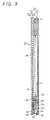
- FIG. 9 is an enlarged sectional view taken on line B-B of FIG. 4
- FIG. 10 is an enlarged sectional view taken on line C-C of FIG. 6
- FIG. 11 is a perspective view showing a second lock mechanism in an enlarged scale.
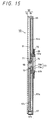
- FIG. 12 through FIG. 15 show a second embodiment of the present invention in which FIG. 12 is a plan side sectional view of the disk cartridge when the opening and closing door is closed at a time of one shell being removed, FIG. 13 is an enlarged sectional view taken on line D-D of FIG. 12, FIG. 14 is a plan side sectional view of the disk cartridge when the opening and closing door is opened at a time of one shell being removed and FIG. 15 is an enlarged sectional view taken on line E-E of FIG. 14.
- a disk cartridge 10 pertaining to the first embodiment showing one concrete example of a disk-shaped information medium cartridge is one which uses a both recording and reproducing optical disk 11 as one concrete example of an information medium.
- this disk cartridge 10 comprises a cartridge housing 12 which is formed by superposing a pair of an upper shell 13 and an lower shell 14, the optical disk 11 accommodated in a state of rotating freely in a disk accommodating room 15 formed in the cartridge housing 12, an opening and closing door 17 capable of opening and closing an opening window 16 formed in the lower shell 14 and the like.
- the upper shell 13 is nearly half circular shaped in its front half and nearly square shaped in its back half, and is made up of a plate-state body and in its inside is provided the disk accommodating room 15 made up of a circular cave-in portion.
- the front-half of the upper shell 13 is made up of, as shown in FIG. 4 through FIG. 7, a middle centre arc portion 13a provided on one side of a nearly middle portion in a width direction which orthogonally intersects a front to back direction and a rear center arc portion 13b provided on the other side of the nearly middle portion in the same width direction.
- a concave portion 18 which extends from the middle centre arc portion 13a to the rear center arc portion 13b, and a step portion 18a is set at a tip end portion of the concave portion 18 on a rear center arc portion 13b side.
- a spring support pin 19 is provided on a middle centre arc portion 13a side of the concave portion 18 and a pin support hole 18b is provided outside this spring support pin 19.
- guide channels 20 and 21 which play roles of positioning, preventing an erroneous insertion and the like upon being loaded on a disk recording and reproducing apparatus are provided extending in a front to rear direction on both side surface portions in the widewise direction of the upper shell 13.
- connection concave portion 22 is connected to a cave-in portion 23 provided in one corner portion of a rear portion in the rear half of the upper shell 13.
- This cave-in portion 23 is partitioned into an outer concave portion 23a and an inside concave portion 23b by a partition-shaped stripe body and a protruding shaft 25 is projectingly provided in the inside concave portion 23b.
- a plurality of screws 13c are provided for screwing the lower shell 14 which is superposed thereon. Further, a pair of positioning holes 26 for positioning this disk cartridge 10 in a predetermined position of a disk recording and reproducing apparatus are provided in both corner portions of the rear portion of the rear half of the upper shell 13.
- the optical disk 11 to be accommodated in the disk accommodating room 15 of the upper shell 13 consists of a thin disc shaped member with a center hole 11a provided in the central portion, and on one surface of its plane portion, provided is an information surface 11b capable of information, which an optical head of an optical pick-up apparatus built in the disk recording and reproducing apparatus opposes.
- a turn table of a disk rotation driving apparatus built in the disk recording and reproducing apparatus is fit in the center hole 11a, and the optical disk 11 is chucked by the turn table is driven into rotation in one body.
- synthetic resin such as polycarbonate (PC), polyolefin and the like are suitable, but it is possible to use not only other synthetic resin but also various kinds of other materials such as glass material, aluminum alloy and the like other than the synthetic resin, which are used as an information medium.
- the lower shell 14 is made up of an upper shell plate 14a and a lower shell plate 14b.
- the upper and lower shell plates 14a and 14b are of nearly the same shape as the upper shell 13 as shown in FIG. 3, and each of front halves thereof is nearly half circular shaped and each of rear halves thereof is made up of a plate body as a plane portion forming nearly a square shape.
- middle center arc portions 27a and 27b are provided on one sides of nearly middle portions in front halves of the respective shells 14a and 14b and, rear centre arc portions 28a and 28b are similarly provided on the other side.
- a stopper portion 29 protruding by a predetermined amount to the rear center arc portion from an edge portion of the middle center arc portion 27b is provided at a nearly middle portion in the front half of the lower shell plate 14b.
- This stopper portion 29 stops a lock pin of the opening and closing door 17 and limits its rotation amount.
- opening windows 16a and 16b which correspond to each other in an up to down direction when they are superposed are provided in the upper and lower shells 14a and 14b, respectively.
- These opening windows 16a and 16b are each made up of an oblong aperture state opening portion with a predetermined width, which extends linearly in a front to back direction with one end set in a nearly middle portion and the other end set in the neighbourhood of a nearly middle portion in the front half.
- a door accommodating concave portion 30 in which the opening and closing door 17 is accommodated in a state of rotating freely is provided on one surface of the upper shell plate 14 in relation to the upper opening window 16a.
- This door accommodating concave portion 30 is so arranged as to correspond to a form in which the opening and closing window 17 stingingly shifts its position by a predetermined angle in order to open as well as close the opening windows 16a and 16b.
- This opening and closing door 17 comprises a rectangular shaped shutter piece 17a capable of completely closing the opening doors 16a and 16b, an arm piece 17b contiguous to one side of the shutter piece 17a in a longitudinal direction and a lock nail 17c provided contiguous to a tip end portion of this opening and closing door 17b.
- a lock pin 31 projecting to its one surface side and this lock pin 31 is made to slidably come into contact with the above-mentioned rear centre arc portions 13b, 28a and 28b.
- an arc shaped escape portion 17d is provided for preventing the shutter piece 17a from overlapping with the opening windows 16a and 16b when the opening windows 16a and 16b are in a state of being opened.
- the arm piece 17b of the opening and closing door 17 is provided by being extended in a direction which forms a diagonal line to the corner portion whereat the lock pin 31 of the shutter piece 17a is fixed. Then, as shown in FIG. 11, at a tip end portion of the arm piece 17, its one part is bent down forward to form a spring receiving tab 17e, and at a position a little returning toward the shutter piece 17a side from the spring receiving tab 17e of the arm piece 17b, a swinging hole 17f, which is a center of a swinging operation of the opening and closing door 17, is provided.
- the projecting shaft 25 of the upper shell 13 is fit in this swinging hole 17f capable of swinging freely.
- the lock nail 17c of the opening and closing door 17 is made up of a U letter shaped member having nail tabs in a front to back direction, and a position of the lock nail 17c in terms of height is adjusted by providing a step portion 17g between the tip portion of the arm piece 17b and the lock nail 17c.
- the door accommodating concave portion 30 in which the opening and closing door 17 having such the form is accommodated comprises a shutter moving portion 30a forming nearly a fan shape corresponding to a moving configuration of the shutter piece 17a and an arm moving portion 30b allowing the moving of the arm piece 17b.
- a concave portion side edge 32a positioned on one side of the shutter moving portion 30a of this door accommodating concave portion 30 extends straight in a front to back direction with a predetermined distance from one side edge of the opening window 16a. Then, as shown in FIG. 4 and FIG. 5, when one side edge of the opening and closing door 17 is in contact with the concave portion side edge 32a, the opening widows 16a and 16b are completely closed by the shutter piece 17a.
- a concave portion side edge 32b positioned on the other side of the shutter moving portion 30a of the door accommodating concave portion 30 is so set as to slantly extend in a forward direction from a position which is swung by a predetermined angle from the other side edge of the opening window 16a.
- a first opening aperture 33 to expose a part of the cave-in portion 23 and a second opening aperture 34 which is set at an outside of a widewise direction of this first opening aperture 34 are provided.
- the second aperture 34 is to expose a part of an elastic member, which will be explained later and is so formed as to correspond to the connection concave portion 22 of the upper shell 14a.
- a block portion 35 projecting toward the upper shell 13 side is provided on a front side of the second opening aperture 34 of the upper shell 14a. This block portion 35 is fit in a part of the outer concave portion 23a of the upper shell B and as a result, it is possible to carry out an approximate positioning of the upper shell plate 14a relative to the upper shell 13.
- a plurality of positioning fit-in holes 36 and respective fit-in holes 36 are set respectively at positions corresponding to screw holes 13c of the upper shell 13.
- a plurality of fit-in convex portions 37 which are to be fit in these fit-in holes 36, are provided by the same number on the inner surface of the lower shell plate 14b.
- a pair of positioning holes 38 for positioning the disk cartridge 10 at a predetermined position in the disk recording and reproducing apparatus are provided. Then, in the neighborhood of one positioning hole 38, a projection 39 fit in the central portion of the projecting shaft 25 which has penetrated the first opening hole 33 is provided.
- a lock arm 40 capable of swinging freely.
- This lock arm 40 comprises: a rod shaped arm main body 40a, a lock nail 40b provided at one end in a longitudinal direction of this arm main body 40a and a swinging pin 40c which is provided on an opposite side of the lock nail 40b of the arm main body 40a and at the same time, its both ends project sideward. Then, one end of the swinging pin 40c is fit in the pin supporting hole 18b of the upper shell 13 capable of swinging freely and the other end thereof is fit in the pin supporting hole 18b provided in the upper shell plate 14a capable of swinging freely, whereby the lock arm 40 is pivotally supported in the cartridge housing 12 capable of swinging freely.
- a torsion spring 41 showing one concrete example of the elastic body is urged toward the inner surface of the lock arm 40.
- a coil portion of this torsion spring 41 is loosely fit in the spring supporting pin 19 and the other end thereof is urged toward a bottom surface of the terraced portion 18.
- the lock nail 40b of the lock arm 40 is always urged toward the terraced portion 18 by a spring force of the torsion spring 41.
- a first lock mechanism for locking the opening and closing door 17 is made up of this lock arm 40 and the torsion spring 41.
- a plate spring body 43 showing one example of the elastic member.
- This plate spring body 43 comprises; a thin and long spring main body 43a, an elastic piece 43b which is formed by bending a little one longitudinal end portion of the spring main body 43a toward a surface direction, and a lock tab 44 and an input tab 45 which are formed so as to stand upright in the same direction by bending in a widewise direction both end edges on a side opposite to the elastic tab 43b of the spring main body 43 a.
- the lock tab 44 of this spring main body 43 is provided with a notch 44a reaching a bottom portion of the spring main body 43 and an engagingly stopping tab 44b is set at an outside of the lock tab 44 by the notch 44a.
- An elastic tab 43b side of the lock tab 44 is made an inclining surface and along the inclining surface, the lock nail 17c of the opening and closing door 17 moves to a surface direction of the optical disk 11, thereby making it possible to take a locked state shown in FIG. 4, FIG. 11 and the like as well as an unlocked state shown in FIG. 6 and the like.
- the input tab 45 of the plate spring body 43 is formed like a L letter shape in cross-section and on its upper surface is provided with an inclining plane 45a gradually descending forward toward the elastic tab 43b side.
- This input tab 45 is supposed to become an input portion for mounting and demounting of the lock nail 17c by the lock tab 44 by elastically deforming the plate spring body 43, and an operating pin 48 provided in the disk recording and reproducing apparatus slides on the inclining plane 45a.
- an engagingly stopping tab 44b side of the spring main body 43a is pushed downward with a result that the lock tab 44 escapes downward, thereby releasing locking of the lock nail 17c.
- a second lock mechanism for locking the opening and closing door 17 is made up of this plate spring body 43.
- This torsion spring 46 is made to be seated on an inner surface of the inner concave portion 23b and the other end is engagingly stopped by the spring receiving tab 17e of the opening and closing door 17.
- ABS resin acrylonitrilebutadienstylene resin
- HIPS high impact proof polystylene
- PP polypropylene
- materials for the opening and closing door 17 and the plate spring body 43 for example, a stainless steel plate and the like are suitable, but other metal-made plate materials can naturally be applied and further, synthetic resin such as HIPS or the like is also used.
- disk cartridge Before the disk cartridge 10 having the above-mentioned arrangement is installed in the disk recording and reproducing apparatus, disk cartridge is placed in a state as shown in FIG. 4 and FIG. 5. That is, the opening and closing door 17 is in a state of completely closing the opening windows 16a and 16b with the spring force of the torsion spring 46, and the opening and closing door 17 is in a state of being immovably locked by the first and the second lock mechanisms.
- a locked state of a first lock releasing mechanism is released by a first lock releasing mechanism.
- This first lock releasing mechanism is, for example, arranged by having an arm member to outwardly swing the lock arm 40, and by swinging the lock arm 40 from the state shown in FIG. 4 and FIG. 5 in an anti-clockwise direction by its arm member against the spring force of the torsion spring 41, the lock nail 40b of the lock arm 40 moves away from the lock pin 31 of the opening and closing door 17, thereby releasing the rocked state by the first locking mechanism.
- the second lock releasing mechanism releases the locked sate by the second lock mechanism.
- This second lock releasing mechanism is, for example, supposed to have an arrangement in which to have the above-mentioned operating pin 48 and is brought into operation with this operation pin 48 entering into the guide channel 20 provided on one side of the disk cartridge 10.
- this operating pin 48 enters into the guide channel 20 and rides on the inclining plane 45a of the input tab 45, because, until then, both ends of the plate spring body 43 are in a state of having been lifted up by being supported at three points by the action of an electric tape 43b of the plate spring body 43, the lock tab 44 side of the plate spring body 43 is elastically deformed downward by an insertion force of the operating pin 48 in FIG. 11. As a result, the lock tab 44 slips out downward from between the lock nails 17c, thereby releasing the locked state by the first locking mechanism.
- This door opening mechanism is, for example, arranged by comprising a pressuring-down member capable of moving the opening and closing door 17 by pressuring down the lock pin 31 against the spring force of the torsion spring 46. Then, by pressuring down the lock pin 31 by the pressuring-down member of this door opening mechanism and by swinging the opening and closing door 17 from a state as shown in FIG. 4 and FIG. 5 to a state as shown in FIG.6 and FIG. 7, the opening windows 16a and 16b are completely opened.
- the above- mentioned first and second lock releasing mechanisms and the door opening mechanism act together in a converse direction, thereby automatically swinging the opening and closing door 17 in the inverse direction, and the opening windows 16a and 16b are closed with this opening and closing door 17. That is, for example, when the pressing force of the lock pin 31 is released by the pressuring-down member of the door opening mechanism and is put in a free state, the opening and closing door 17 swings to shift its position from the state as shown in FIG. 6 and FIG. 7 to the state as shown in FIG. 4 and FIG. 5 by the spring force of the torsion spring 41 which acts on the arm tab 17b, and a former state in which the opening windows 16a and 16b are closed is restored.
- the opening and closing door 17 is so structured to be swung along a plane of the plane portion by placing the opening and closing door 17 between the upper and lower shell plates 14a and 14b of the lower shell 14 in which the opening windows 16a and 16b of the cartridge housing 12 are provided, it became possible to reduce as much as possible the gap formed between the cartridge housing 12 and the opening and closing door 17. Therefore, it became possible to effectively restrain minute dust from entering into the cartridge housing through the gap between the cartridge housing 12 and the opening and closing door 17. Further, it is possible to beforehand prevent an accident in which a user erroneously opens the opening and closing door 17 as the opening and closing door 17 is accommodated in the lower shell 14. And further, because there are provided dual lock mechanisms in the opening and closing door 17, it is possible to surely prevent an accident in which a user erroneously opens the opening and closing door 17.
- a disk cartridge 50 according to a second embodiment of the present invention is, as shown in FIG. 12 through FIG. 15, one in which an opening and closing door 57 is exposed outside a cartridge housing 52.
- This disk cartridge 50 comprises: a cartridge housing 52 which is arranged by superposing a pair of an upper shell 53 and a lower shell 54, an optical disk 51 which is accommodated capable of rotating freely in a disk accommodating room 55 formed in this cartridge housing 52, the opening and closing door 57 capable of opening and closing an opening window 56 formed in the lower shell 54 and the like.
- the upper shell 53 is made up of a plate shape body comparatively thin in thickness with a front half being of a semi-circular shape and a rear half being of a square shape, and a screw shaft portion 58 projecting downward is provided nearly in the middle portion of its inside face.
- the lower shell 54 is made up of a plate shape body as a plane portion having an appropriate thickness with a front half similarly being of a semi-circular shape and a rear half being of a square shape, and a disk accommodating room 55 consisting of a circular shaped concave portion is provided on its inside face.
- guide channels 60 and 61 which play a role of positioning when it is loaded on the disk recording and reproducing apparatus and of preventing erroneous insertion and the like, are provided on both side portions in a widewise direction of the lower shell 54 extending in a front to back direction.
- a circular channel 59 concentric with this disk accommodating room 55 is provided outside the disk accommodating room 55 of the lower shell 54.
- This circular channel 59 is so set as to start in the neighbourhood of one guide channel 60 and to cover nearly 3/4 of a circumference of the disk accommodating room 55 and an arm accommodating concave portion 63 in which an engagingly stopping arm 62 showing one concrete example of an engagingly stopping member is accommodated capable of swinging freely is contiguously connected to its starting edge portion.
- a supporting pin 63a is projectingly provided in this arm accommodating concave portion 63 and a base end of the engagingly stopping arm 62 is supported by this supporting pin 63a capable of swinging freely.
- the engagingly stopping arm 62 comprises: an engagingly stopping nail 62a provided at its tip end and an input projection 62b which is set between this engagingly stopping nail 62a and a hole for the supporting hole 63a.
- the engagingly stopping nail 62a and the input projection 62b of the engagingly stopping arm 62 are projected in the same direction and are always urged toward the guide channel 60 side by a torsion spring 64 showing a concrete example of an elastic body. That is, a coil portion of the torsion spring 64 is loosely fit around the supporting pin 63a with one end being engagingly stopped by a spring receiving tab 63b in the arm accommodating concave portion 63 and the other end being seated on the engagingly stopping arm 62.
- This engagingly stopping arm 62 is set such that the engagingly stopping nail 62a and the input projection 62b face a continuously connection opening 65 which continuously connects the guide channel 60 with the arm accommodating concave portion 63. Then, there is a setting such that the input projection 62b projects into the guide channel 60 by a spring force of the torsion spring 64 while the engagingly stopping nail 62a is accommodated in the arm accommodating concave portion 63.
- a ribbon shaped lock band 66 is accommodated capable of sliding freely in the circle channel 59 so that one end of the engagingly stopping arm 62 faces the engagingly stopping nail 62a.
- an engagingly stopping hole by which the engagingly stopping nail 62a is engagingly stopped capable of being mounted and demounted is opened, and in a nearly middle portion of a front half of the lower shell 54 which is an on-the-way portion in a longitudinal direction, the opening and closing door 57 is integrally fixed.
- a third locking mechanism for locking the opening and closing door 57 at a time of the opening window 56 being in a closed state is made up of this lock band 66, the torsion spring 64 and the engagingly stopping arm 62.
- an operating concave portion 67 for carrying out swinging operation of the opening and closing door 57.
- This operating concave portion 67 is extended long in a lateral direction from a nearly middle portion of the front half of the lower half 54 to a portion reaching the other guide channel 61, and a notch portion 67a where the opening and closing door 57 passes capable of sliding freely is provided in a projected stripe opposing this, which is set between the disk accommodating room 55 and the circle channel 59.
- a hub hole 68 is opened in a central portion of the disk accommodating room 55 in the middle or the substantial centre of the lower shell 54 and the opening window 56 which extends forward succeeding this hub hole 68 and nearly reaches the middle portion of the front half is provided.
- This opening window 56 and the hub hole 68 are made to be freely opened and closed by the opening and closing door 57 mounted on the lower shell 54.
- This opening and closing door 57 is cross-sectionally U letter shaped and comprises a shutter piece 57a for opening and closing the opening window 56 and the hub hole 68, an peripheral tab 57b succeeding a peripheral edge of the shutter 57a and a base piece 57c which is so provided as to succeed the peripheral tab 57b and oppose the shutter piece 57a.
- a inserting hole 57d At the base end of the shutter piece 57a of the opening and closing 57 is provided a inserting hole 57d, and a part of the peripheral tab 57b is swelled so that a finger and the like can easily catch it.
- the base piece 57c of the opening and closing door 57 is disposed along an inner surface of the upper shell 53, and an operating pin 70 which projects to a shutter piece side is integrally provided in an inner peripheral end thereof.
- the optical disk 51 accommodated in the disk accommodating room 55 of the cartridge 52 comprises a disk portion 51a having a nut hole 71 at its centre portion and a tube shaft portion 51b provided at the centre portion on one surface of the optical disk portion 51a.
- the tube shaft portion 51b penetrates through the hub hole 68 of the lower shell 54 and the inserting hole 57d of the opening and closing door 57 to project to a lower surface side.
- the shutter piece 57a is prevented from coming off by a ring shaped stopping ring 72 fixed at a tip end portion of the tube shaft portion 51b.
- a nut member 73 is loosely fit in the nut hole 71 and a screw shaft portion 58 of the upper shell 53 is engaged with a screw portion provided on an inner peripheral surface thereof.
- This nut member 73 comprises a head portion 73a for preventing itself from coming off the nut hole 71 and a slit 73b provided on an outer peripheral surface extending in parallel with the centre of the screw hole.
- the operating pin 70 of the opening and closing door 57 is slidably inserted into the slit 73b of the nut member 73.
- a chucking plate 74 consisting of an iron plate and the like for being installed on a turntable is fit in an inside of the tube shaft portion 51b covering the head portion 73a side of the nut member 73.
- polycarbonate (PC) and the like are suitable, but it is possible to use not only other synthetic resin but also various kinds of other materials such as glass material, aluminum alloy and the like other than the synthetic resin.
- synthetic resin such as ABC resin, HIPS and the like are similarly suitable, but it is possible to use other synthetic resin but also other materials such as aluminum alloy and the like.
- the materials of the opening and closing door 57 for example, stainless steel with excellent resistance to corrosion is suitable, but it goes without saying that not only aluminum alloy and the like but also synthetic resin can be used.
- the disk cartridge 50 having such the arrangement, as shown in FIG. 12 and FIG. 13, when the opening window 56 is closed by the opening and closing door 57, the nut member 73 is pulled in an upward direction and the optical disk 51 is in a state of having been lifted. Therefore, the shutter piece 57a of the opening and closing door 57 is lifted by the tube shaft portion 51b of the optical disk 51 and the shutter piece 57a becomes a state of being placed in pressured contact with a lower surface of the lower shell 54. As a result, the gap between the shutter piece 57a and the lower shell 54 is made as smaller as possible, thereby making it possible to effectively restrain the minute dust from entering. Further, because the opening and closing door 57 is locked by the third locking mechanism, it is possible to beforehand prevent an accident in which a user erroneously opens the opening and closing door 57.
- the engagingly stopping arm 62 When the operation pin enters into one guide channel 60 and pushes down with pressure the input projection 62b of the engagingly stopping arm 62 by installing the disk cartridge 50 in the disk recording and reproducing apparatus while the opening and closing door 57 is in a state of being closed, the engagingly stopping arm 62 is pushed back toward the inside against the spring force of the torsion spring 64. As a result, the engagingly stopping nail 62a of the engagingly stopping arm 62 retreats inside and gets out of the engagingly stopping hole of the lock band 66, thereby releasing the lock by the third locking mechanism.
- the optical disk 51 is chucked by raising a turntable on the disk recording and reproducing apparatus side or the like.
- the optical disk 51 is integrated with the turn table in terms of a rotating direction, thereby making it possible to write (recording) and read out (reproducing) an information signal in and from the optical disk 51.
- the present invention is not limited to the above-mentioned embodiments.
- the present invention can be applied to magnetic disks such as an magneto-optical disk, a floppy disk and the like and other various kinds of information media.
- the example in which the present invention is applied to the dual purpose recording and reproducing disk recording and reproducing apparatus as an information recording medium has been given, but needless to say, the present invention can be applied to a disk memory apparatus capable of only either of recording and reproducing.
- the cartridge housing can be structured such that access can be simultaneously made from top and bottom of the cartridge housing by boring opening windows on plane portions of both surfaces.
- the use of the torsion spring as an elastic body has been explained, but needles to say, it is possible to use not only plate spring and other spring materials but also rubber state elastic bodies such as rubber or synthetic resin akin to this and the like. In this manner, the present invention can be subjected to various changes within a range of departing its gist.
- the opening and closing door is swung along a plane of the plane portion of the cartridge housing, it is possible to reduce the gap between the opening and closing door and the cartridge housing as small as possible, and hence, it is possible to effectively restrain the minute dust from entering into the cartridge housing through the gap between the cartridge housing and the opening and closing door. Further, because the opening and closing door is locked by the locking mechanism when the opening windows are closed, such an effect can be obtained that an occurrence of an accident in which a user erroneously opens the opening and closing door can be beforehand prevented.
Abstract
Description
- The present invention relates to a recording medium (memorising medium) cartridge such as a disk-shaped information recording medium cartridge in which an information recording medium such as an optical disk, a magneto-optical disk and the like is accommodated in a state of rotating freely and particularly to a recording medium cartridge capable of effectively restraining minute dust from entering in a cartridge housing while it is in a state of being reserved.
- In the past, generally, as an information recording cartridge in whose housing an information recording medium capable of recording and/or reproducing information such as audio, video, computer data and the like is accommodated in a
state of rotating freely, for example, a cartridge having an arrangement as shown in FIG. 1 has been known. This information recording cartridge is a disk cartridge 1 containing therein a write-once type magnetic disk D where a user can record and
write in information such as computer data and the like later on and has an outward appearance shape as shown in FIG. 1. - That is, this disk cartridge 1 comprises a cartridge housing 2 which is made up of a pair of upper and
lower shells 2a and 2b, and an magneto-optical disk 4 accommodated in a state of rotating freely in a disk accommodatingroom 3 of this cartridge housing 2 and the like. On both surfaces of the upper and lower
of the cartridge housing 2 are provided upper andlower opening windows 5 extending to one side from a central portion and thisopening window 5 is made capable of being opened and closed by an opening and closingdoor 6 which is made capable of sliding along its one side. Then, at a central portion of the magneto-optical disk 4 is provided a hub portion 7 having acentre hole 7a which is chucked to a turntable provided on a main body side of an information apparatus and this hub 7 is made to oppose a central portion of theopening window 5. - However, as the conventional disk cartridge having such an arrangement is structured such that the opening and closing
door 6 is formed like a U letter shape to be fit in one side of the cartridge housing 2 and theopening window 5 is opened and
closed by sliding the opening and closingdoor 6 along its one side, there has been a problem that a big gap forms between the cartridge housing 2 and the opening and closingdoor 6, thereby making it impossible to prevent the minute dust from intruding. - In this case, when the dust, which has intruded in the cartridge housing 2, attaches itself to a surface of an information surface of the magneto-
optical disk 4, read-out or write-in beam is shielded and the information surface is damaged by the dust, thereby making it impossible to carry out a read/write of information normally. Particularly, in a case of an information device with a large capacity, the effect of even minute dust cannot be negligible and hence, there is a demand for a disk cartridge capable of preventing the intrusion of even the minute dust. - Further, in the above-mentioned conventional disk cartridge 1, because the opening and closing
door 6 is located at a portion where it is easily touched by a user's hand, there is a fear that the user opens theopening window 5 by erroneously
sliding the opening and closingdoor 6. Further, because the opening and closingdoor 6 moves linearly along one side of the cartridge housing 2, there is a problem that a surface area of the cartridge housing 2 can not be made smaller. - Also, as another example of the conventional medium cartridge, for example, there is a disk cartridge as is stated in a public bulletin of Japanese laid-open patent publication No. 7-6493. This disk cartridge comprises an upper case whose remaining half is circular-shaped and a remaining half is square-shaped, a lower case having the same shape as that of the upper case, two notch portions provided in a position which opens by 90 degrees in the circular shaped portions of the upper and lower cases when viewed from a disk centre, a window provided at a centre of the two notch portions of the lower case, a swinging shutter which covers the notch portions and the window and is fit in the circular portions of the upper and lower cases and a driven roller provided in a position symmetrical to the notch portions relative to the disk centre in the upper and lower cases.
- Although this disk cartridge is arranged such that the swinging shutter moves curvedly in the circular portion of the upper and lower cases, because the swinging shutter is formed in
the same U letter shape as the above-mentioned opening and closingdoor 6 and this swinging shutter is so structured to fit in the circular portions of the upper and lower cases, a large gap similarly forms between the upper and lower cases and the swinging shutter, thereby giving birth to the problem that minute dust can not be prevented from intruding. - The present invention is implemented in view of these problems with the conventional disk cartridge.
- According to an aspect of the present invention, there is proposed a disk-shaped information recording medium cartridge which comprises:
- a cartridge housing in which a disk-shaped information recording medium accommodating room is formed by superposing a pair of shells;
- a disk-shaped information recording medium accommodated capable of rotating freely in the disk-shaped information recording medium accommodating room;
- an opening window formed in one shell of the pair of shells, and which exposes an information recording surface of the disk-shaped information recording medium; and
- an opening and closing door which is installed in one shell of the pair of shells to be capable of swinging freely and opens and closes the opening window by its swinging with a plane of one shell of the pair of shells as a guide, wherein the plane of the one shell is substantially parallel to the information recording surface of the disk-shaped information recording medium rotatably accommodated in the disk-shaped information recording medium accommodating room.
- Since the present invention is arranged in the above-mentioned manner, the opening and closing door is swung along the plane of the plane portion on which the opening window of the cartridge housing is provided, whereby it is possible to reduce the gap formed between the cartridge housing and the opening and closing door as small as possible and to effectively restrain intrusion of the minute dust into the cartridge housing when it is in a state of being reserved.
- Preferably a centre hole is provided in a central portion of said disk-shaped information recording medium, a nut member capable of supporting said disk-shaped information recording medium is provided by being fit in the centre hole to swing freely, said nut member is integrated with said opening and closing door in a swinging direction and is movably connected in a direction perpendicular to said swinging direction, and further, a screw shaft portion provided in the central portion
of one shell out of said pair of shells is engaged with the nut member and a winding direction of said screw shaft portion is set such that the nut member and one shell move in a direction to distance themselves from each other when the opening and
closing door moves in a direction away from said opening window. - Embodiments of the present invention can solve the above-mentioned problems by putting in place an arrangement that an opening window is provided on at least one plane portion of the cartridge housing as well as by swinging the opening and closing door along the plane of this plane portion to carry out a measure against the dust for reducing as small as possible the gap which forms between the cartridge
housing and the opening and closing door. - Embodiments of the present invention will now be described by way of non-limitative example with reference to the attached drawings in which:
- FIG. 1 is a perspective view showing a conventional disk cartridge;
- FIG. 2 is a perspective view of a disk cartridge showing an example of a first embodiment of a disk-shaped information recording medium cartridge of the present invention with an opening window being in an opened state and seen from a lower surface side thereof;
- FIG. 3 is an exploded perspective view of the disk cartridge shown in FIG. 2 in a state seen from the lower surface side thereof;
- FIG. 4 is a plan view of the disk cartridge shown in FIG. 2 in a state in which a lower shell plate is removed and the opening window is closed;
- FIG. 5 is a plan view of the disk cartridge shown in FIG. 2 in a state in which an upper shell plate is further removed and the opening window is closed;
- FIG. 6 is a plan view of the disk cartridge shown in FIG. 2 in a state in which the lower shell plate is removed and the opening window is opened;
- FIG. 7 is a plan view of the disk cartridge shown in FIG. 2 in a state in which the upper shell plate is further removed and the opening window is opened;
- FIG. 8 is an enlarged cross-sectional view of the disk cartridge shown in FIG. 2 taken on line A-A in FIG. 4;
- FIG. 9 is an enlarged cross-sectional view of the disk cartridge shown in FIG. 2 taken on line B-B in FIG. 4;
- FIG. 10 is an enlarged cross-sectional view of the disk cartridge shown in FIG. 2 taken on line C-C in FIG. 6;
- FIG. 11 is a perspective view showing a second locking mechanism of the disk cartridge shown in FIG. 2 in an enlarged scale;
- FIG. 12 is a plan view of the disk cartridge showing a second embodiment of the disk-shaped information recording medium cartridge of the present invention in a state in which the lower shell plate thereof is sectioned and the opening window is closed;
- FIG. 13 is an enlarged cross-sectional view of the disk cartridge shown in FIG. 12 taken on line D-D;
- FIG. 14 is a plan view of the disk cartridge shown in FIG. 12 in a state in which the lower shell plate is sectioned and the opening window is opened; and
- FIG. 15 is an enlarged cross-sectional view of the disk cartridge shown in FIG. 12 taken on line D-D in FIG. 14.
- FIG. 2 through FIG. 11 show a first embodiment of the present invention
in which FIG. 2 is a perspective view of a disk cartridge such as a disk-shaped information recording medium cartridge when looked from a lower surface side, FIG. 3 is an exploded perspective view of the disk cartridge, FIG. 4 is a plan view of
the disk cartridge when an opening and closing door is closed at a time of a lower shell plate being removed, FIG. 5 is a plan view of the disk cartridge when the opening and closing door is closed at a time of an upper shell being further removed, FIG. 6 is a plan view of the disk cartridge when the opening and closing door is opened at a time of the lower shell plate being removed, FIG. 7 is a plan view of the disk cartridge when the opening and closing door is opened at a time of the upper shell being further removed, FIG. 8 is an enlarged sectional view taken on line A-A of (in) FIG. 4, FIG. 9 is an enlarged sectional view taken on line B-B of FIG. 4, FIG. 10 is an enlarged sectional view taken on line C-C of FIG. 6 and FIG. 11
is a perspective view showing a second lock mechanism in an enlarged scale. - Also, FIG. 12 through FIG. 15 show a second embodiment of the present invention in which FIG. 12 is a plan side sectional view of the disk cartridge when the opening and closing door is closed at a time of one shell being removed, FIG. 13 is an enlarged sectional view taken on line D-D of FIG. 12, FIG. 14 is
a plan side sectional view of the disk cartridge when the opening and closing door is opened at a time of one shell being removed and FIG. 15 is an enlarged sectional view taken on line E-E of FIG. 14. - A
disk cartridge 10 pertaining to the first embodiment showing one concrete example of a disk-shaped information medium cartridge is one which uses a both recording and reproducingoptical disk 11 as one concrete example of an information medium. With a lower surface side being upward as shown in FIG. 2 and FIG. 3, thisdisk cartridge 10 comprises acartridge housing 12 which is formed by superposing a pair of anupper shell 13 and anlower shell 14, theoptical disk 11 accommodated in a state of rotating freely in adisk accommodating room 15 formed in thecartridge housing 12, an opening and closingdoor 17 capable of opening and closing anopening window 16 formed in thelower shell 14 and the like. - The
upper shell 13 is nearly half circular shaped in its front half and nearly square shaped in its back half, and is made up of a plate-state body and in its inside is provided thedisk accommodating room 15 made up of a circular cave-in
portion. The front-half of theupper shell 13 is made up of, as shown in FIG. 4 through FIG. 7, a middlecentre arc portion 13a provided on one side of a nearly middle portion in a width direction which orthogonally intersects a front to back direction and a rearcenter arc portion 13b provided on the other side of the nearly middle portion in the same width direction. There is an arrangement such that an arc centre of the front-half middlecenter arc portion 13a of theupper shell 13 is set at a nearly central porion of thedisk accommodating room 15 and an arc center of the rearcenter arc portion 13b is set in the neighborhood of a back corner portion of a back half, and a lock pin, which will be mentioned later, of the opening and closingdoor 17 is guided by the rearcenter arc portion 13b. - Further, in the front-half center portion of the
upper shell 13 is provided aconcave portion 18 which extends from the middlecentre arc portion 13a to the rearcenter arc portion 13b, and a step portion 18a is set at a tip end portion of the
concave portion 18 on a rearcenter arc portion 13b side. Then, aspring support pin 19 is provided on a middlecentre arc portion 13a side of theconcave portion 18 and apin support hole 18b is provided outside thisspring support pin 19. Further,guide channels upper shell 13. - These
guide channels center arc portion 13a and the rearcentre arc portion 13b and the other ends extended in the neighborhood of a rear portion of the rear half. Then, in the
neighborhood of the rear portion of theguide channel 20 is provided a connectionconcave portion 22. This connectionconcave portion 22 is connected to a cave-inportion 23 provided in one corner portion of a rear portion in the rear half of theupper shell 13. This cave-inportion 23 is partitioned into an outerconcave portion 23a
and an insideconcave portion 23b by a partition-shaped stripe body and a protrudingshaft 25 is projectingly provided in the insideconcave portion 23b. Then, in the circumference of thedisk accommodating room 15, a plurality ofscrews 13c are provided for screwing thelower shell 14 which is superposed thereon. Further, a pair of positioning holes 26 for positioning thisdisk cartridge 10 in a predetermined position of a disk recording and reproducing apparatus are provided in both corner portions of the rear portion of the rear half of theupper shell 13. - The
optical disk 11 to be accommodated in thedisk accommodating room 15 of theupper shell 13 consists of a thin disc shaped member with acenter hole 11a provided in the central portion, and on one surface of its plane portion,
provided is aninformation surface 11b capable of information, which an optical head of an optical pick-up apparatus built in the disk recording and reproducing
apparatus opposes. A turn table of a disk rotation driving apparatus built in the disk recording and reproducing apparatus is fit in thecenter hole 11a, and theoptical disk 11 is chucked by the turn table is driven into rotation in one body. - As for materials for this
optical disk 11, for example, synthetic resin such as polycarbonate (PC), polyolefin and the like are suitable, but it is possible to use not only other synthetic resin but also various kinds of other materials such
as glass material, aluminum alloy and the like other than the synthetic resin, which are used as an information medium. - Also, the
lower shell 14 is made up of anupper shell plate 14a and alower shell plate 14b. The upper andlower shell plates upper shell 13 as shown in FIG. 3, and each of front halves thereof is
nearly half circular shaped and each of rear halves thereof is made up of a plate body as a plane portion forming nearly a square shape. Then, middlecenter arc portions respective shells centre arc portions stopper portion 29 protruding by a predetermined amount to the rear center arc portion from an edge portion of the
middlecenter arc portion 27b is provided at a nearly middle portion in the front half of thelower shell plate 14b. Thisstopper portion 29 stops a lock pin of the opening and closingdoor 17 and limits its rotation amount. - Further, opening
windows lower shells windows concave portion 30 in which the opening and closingdoor 17 is accommodated in a state of rotating freely is provided on one surface of theupper shell plate 14 in relation to theupper opening window 16a. This door accommodatingconcave portion 30 is so arranged as to correspond to a form in which the opening and closingwindow 17 stingingly shifts its position by a predetermined angle in order to open as well as close theopening windows - Prior to explaining a form of this door accommodating
concave portion 30, first of all, the opening and closingdoor 17 will be explained. This opening and closingdoor 17, as shown in FIG. 3, comprises a rectangular shapedshutter piece 17a capable of completely closing the openingdoors arm piece 17b contiguous to one side of theshutter piece 17a in a longitudinal direction and alock nail 17c provided contiguous to a tip end portion of this opening and closingdoor 17b. In an outside edge portion of theshutter piece 17a is provided alock pin 31 projecting to its one surface side and thislock pin 31 is made to slidably come into contact with the above-mentioned rearcentre arc portions
inner side of thisshutter piece 17a, an arc shapedescape portion 17d is provided for preventing theshutter piece 17a from overlapping with theopening windows opening windows - Further, the
arm piece 17b of the opening and closingdoor 17 is provided by being extended in a direction which forms a diagonal line to the corner portion whereat thelock pin 31 of theshutter piece 17a is fixed. Then, as shown in FIG. 11, at a tip end portion of thearm piece 17, its one part is bent down forward to form a spring receiving
tab 17e, and at a position a little returning toward theshutter piece 17a side from thespring receiving tab 17e of thearm piece 17b, a swinginghole 17f, which is a center of a swinging operation of the opening and closingdoor 17, is provided. The projectingshaft 25 of theupper shell 13 is fit in this swinginghole 17f capable of swinging freely. Also, thelock nail 17c of the opening and closingdoor 17 is made up of a U letter shaped member having nail tabs in a front to back direction, and a position of thelock nail 17c in terms of height is adjusted by providing a step portion 17g between the tip portion of thearm piece 17b and thelock nail 17c. - The door accommodating
concave portion 30 in which the opening and closingdoor 17 having such the form is accommodated comprises ashutter moving portion 30a forming nearly a fan shape corresponding to a moving configuration of theshutter piece 17a and anarm moving portion 30b allowing the moving of the arm
piece 17b. A concaveportion side edge 32a positioned on one side of theshutter moving portion 30a of this door accommodatingconcave portion 30 extends straight in a front to back direction with a predetermined distance from one side edge of theopening window 16a. Then, as shown in FIG. 4 and FIG. 5, when one side edge of the opening and closingdoor 17 is in contact with the concaveportion side edge 32a, the openingwidows shutter piece 17a. - Also, a concave
portion side edge 32b positioned on the other side of theshutter moving portion 30a of the door accommodatingconcave portion 30 is so set as to slantly extend in a forward direction from a position which is swung by a
predetermined angle from the other side edge of theopening window 16a. As a result, as shown in FIG. 6 and FIG. 7, when the other side edge of the opening and closingdoor 17 is in contact with the concaveportion side edge 32b, theshutter piece 17a having theescape portion 17d can completely open theopening window - Further, in a corner portion opposing in a diagonal direction the rear portion
center arc portion 28a of thearm moving portion 30b of the door accommodatingconcave portion 30, afirst opening aperture 33 to expose a part of the cave-inportion 23 and asecond opening aperture 34 which is set at an outside of a widewise direction of thisfirst opening aperture 34 are provided. Thesecond aperture 34 is to expose a part of an elastic member, which will be explained later and is so formed as
to correspond to the connectionconcave portion 22 of theupper shell 14a. Then, on a front side of thesecond opening aperture 34 of theupper shell 14a, ablock portion 35 projecting toward theupper shell 13 side is provided. Thisblock portion 35 is fit in a part of the outerconcave portion 23a of the upper shell B and as a result, it is possible to carry out an approximate positioning of theupper shell plate 14a relative to theupper shell 13. - On an outside of the door accommodating concave portion of this
upper shell 14 are provided a plurality of positioning fit-inholes 36 and respective fit-inholes 36 are set respectively at positions corresponding to screwholes 13c of theupper shell 13. Then, a plurality of fit-inconvex portions 37, which are to be fit in these fit-inholes 36, are provided by the same number on the inner surface of thelower shell plate 14b. By only fitting the fit-inconvex portions 36 in the fit-inholes 37 and superposing the upper andlower shells plates shell plates screw portion 13c after inserting a shaft portion of set screws through these, it becomes possible to make up thecartridge housing 12 by integrally assembling the upper andlower shells - Further, in the neighborhood of both the corner portions in the rear half of the
upper shell plate 14a, a pair of positioning holes 38 for positioning thedisk cartridge 10 at a predetermined position in the disk recording and reproducing apparatus are provided. Then, in the neighborhood of onepositioning hole 38, aprojection 39 fit in
the central portion of the projectingshaft 25 which has penetrated thefirst opening hole 33 is provided. - Also, in the
concave portion 18 of theupper shell 13 is installed alock arm 40 capable of swinging freely. Thislock arm 40 comprises: a rod shaped armmain body 40a, alock nail 40b provided at one end in a longitudinal direction of this armmain body 40a and a swingingpin 40c which is provided on an opposite side of thelock nail 40b of the armmain body 40a and at the same time, its both ends project sideward. Then, one end of the swingingpin 40c is fit in thepin supporting hole 18b of theupper shell 13 capable of swinging freely and the other end thereof is fit in thepin supporting hole 18b provided in theupper shell plate 14a capable of swinging freely, whereby thelock arm 40 is pivotally supported in thecartridge housing 12 capable of swinging freely. - One end of a
torsion spring 41 showing one concrete example of the elastic body is urged toward the inner surface of thelock arm 40. A coil portion of thistorsion spring 41 is loosely fit in thespring supporting pin 19 and the other end thereof is urged toward a bottom surface of theterraced portion 18. Thelock nail 40b of thelock arm 40 is always urged toward theterraced portion 18 by a spring force of thetorsion spring 41. A first lock mechanism for locking the opening and closingdoor 17 is made up of thislock arm 40 and thetorsion spring 41. - Also, in the outer
concave portion 23a of theupper shell 13 is accommodated aplate spring body 43 showing one example of the elastic member. Thisplate spring body 43, as enlargedly shown in FIG. 11, comprises; a thin and long springmain body 43a, anelastic piece 43b which is formed by bending a little one longitudinal end portion of the springmain body 43a toward a surface direction, and alock tab 44 and aninput tab 45 which are formed so as to stand upright in the same direction by bending in a widewise direction both end edges on a side opposite to theelastic tab 43b of the springmain body 43 a. - The
lock tab 44 of this springmain body 43 is provided with anotch 44a reaching a bottom portion of the springmain body 43 and an engagingly stoppingtab 44b is set at an outside of thelock tab 44 by thenotch 44a. Anelastic tab 43b side of thelock tab 44 is made an inclining surface and along the inclining surface, thelock nail 17c of the opening and closingdoor 17 moves to a surface direction of theoptical disk 11, thereby making it possible to take a locked state shown in FIG. 4, FIG. 11 and the like as well as an unlocked state shown in FIG. 6 and the like. - Also, the
input tab 45 of theplate spring body 43 is formed like a L letter shape in cross-section and on its upper surface is provided with an incliningplane 45a gradually descending forward toward theelastic tab 43b side. This input
tab 45 is supposed to become an input portion for mounting and demounting of thelock nail 17c by thelock tab 44 by elastically deforming theplate spring body 43, and anoperating pin 48 provided in the disk recording and reproducing apparatus slides on the incliningplane 45a. By this, an engagingly stoppingtab 44b side of the
springmain body 43a is pushed downward with a result that thelock tab 44 escapes downward, thereby releasing locking of thelock nail 17c. A second lock mechanism for locking the opening and closingdoor 17 is made up of thisplate spring body 43. - The opening and closing
door 17, which is doubly locked by the first and second lock mechanisms in this manner, is always urged toward a direction to close theopening windows torsion spring 46 showing one example of an elastic body loosely fit in the projectingshaft 25 which is loosely inserted through its swinginghole 17f. One end of thistorsion spring 46 is made to be seated on an inner surface of the innerconcave portion 23b and the other end is engagingly stopped by thespring receiving tab 17e of the opening and closingdoor 17. Therefore, when an external force acting on the opening and closingdoor 17 is only a spring force by thetorsion spring 46, thelock nail 17c climbs over thelock tab 44 to enter into thenotch 44a by the spring force and its one nail portion becomes a state of being in contact with an inner edge of theengagingly stopping portion 44b. - Meanwhile, as for materials for the
upper shell 3 and the upwardlower shell plate 14a and the downwardlower shell plate 14b, for example, ABS resin (acrylonitrilebutadienstylene resin) is suitable, but other synthetic resin such as HIPS (high impact proof polystylene), PP (polypropylene) and the like can be used. Further, as materials for the opening and closingdoor 17 and theplate spring body 43, for example, a stainless steel plate and the like are suitable, but other metal-made plate materials can naturally be applied and further, synthetic resin such as HIPS or the like is also used. - Before the
disk cartridge 10 having the above-mentioned arrangement is installed in the disk recording and reproducing apparatus, disk cartridge is placed in a state as shown in FIG. 4 and FIG. 5. That is, the opening and closingdoor 17 is in a state of completely closing theopening windows torsion spring 46, and the opening and closingdoor 17 is in a state of being immovably locked by the first and the second lock mechanisms. - By inserting the
disk cartridge 10 in such a state in the disk recording and reproducing apparatus, locked states of the first and second locking mechanisms are released by the first and second locking mechanisms provided in the disk recording and reproducing apparatus and thereafter, theopening windows door 17 by a door opening mechanism. - First of all, when the
disk cartridge 10 is inserted in the disk recording and reproducing apparatus, a locked state of a first lock releasing mechanism is released by a first lock releasing mechanism. This first lock releasing mechanism is, for
example, arranged by having an arm member to outwardly swing thelock arm 40, and by swinging thelock arm 40 from the state shown in FIG. 4 and FIG. 5 in an anti-clockwise direction by its arm member against the spring force of thetorsion spring 41, thelock nail 40b of thelock arm 40 moves away from thelock pin 31 of the opening and closingdoor 17, thereby releasing the rocked state by the first locking mechanism. - Concurrently with or before and after this, the second lock releasing mechanism releases the locked sate by the second lock mechanism. This second lock releasing mechanism is, for example, supposed to have an arrangement in which to have the above-mentioned
operating pin 48 and is brought into operation with thisoperation pin 48 entering into theguide channel 20 provided on one side of thedisk cartridge 10. When thisoperating pin 48 enters into theguide channel 20 and rides on the incliningplane 45a of theinput tab 45, because, until then, both ends of theplate spring body 43 are in a state of having been lifted up by being supported at three points by the action of anelectric tape 43b of theplate spring body 43, thelock tab 44 side of theplate spring body 43 is elastically deformed downward by an insertion force of theoperating pin 48 in FIG. 11. As a result, thelock tab 44 slips out downward from between the lock nails 17c, thereby releasing the locked state by the first locking mechanism. - As a result, two locked states of the opening and closing
door 17 are released, but because the opening and closingdoor 17 is urged in a direction to close theopening windows torsion spring 46, the opening and closingdoor 17 can not be moved in this situation. Then, next, the opening and closingdoor 17 is swung by a door opening mechanism. This door opening mechanism is, for example, arranged by comprising a pressuring-down member capable of moving the opening and closingdoor 17 by pressuring down thelock pin 31 against the spring force of thetorsion spring 46. Then, by pressuring down thelock pin 31 by the
pressuring-down member of this door opening mechanism and by swinging the opening and closingdoor 17 from a state as shown in FIG. 4 and FIG. 5 to a state as shown in FIG.6 and FIG. 7, theopening windows - Contrary to this, when the
disk cartridge 10 is taken out from the disk recording and reproducing apparatus, the above- mentioned first and second lock releasing mechanisms and the door opening mechanism act together in a converse direction, thereby automatically swinging the opening and closingdoor 17 in the inverse direction, and theopening windows door 17. That is, for example, when the pressing force of thelock pin 31 is released by the pressuring-down member of the door opening mechanism and is put in a free state, the opening and closingdoor 17 swings to shift its position from the state as shown in FIG. 6 and FIG. 7 to the state as shown in FIG. 4 and FIG. 5 by the spring force of thetorsion spring 41 which acts on thearm tab 17b, and a former state in which theopening windows - When the
operating pin 48 of the second lock releasing mechanism retreats in a link motion with this, because theplate spring body 43 has an elastic deformation released and reverts to a former state, itslock tab 44 enters into the lock nails 17c of the opening and closingdoor 17. As a result, a first stair locked state of the opening
and closingdoor 17 by the first lock releasing mechanism is secured. In the same way as this, thelock arm 40 is returned to a former state by the spring force of thetorsion spring 41 as regulation of thelock arm 40 by the arm member of the first lock releasing mechanism is released. As a result, thelock nail 40b of thelock arm 40 is engaged with thelock pin 31, which makes it possible to secure a second step locked state of the opening and closingdoor 17 by the first locking mechanism. - In this manner, according to the
disk cartridge 10 concerning the first embodiment, because the opening and closingdoor 17 is so structured to be swung along a plane of the plane portion by placing the opening and closingdoor 17 between the upper andlower shell plates lower shell 14 in which theopening windows cartridge housing 12 are provided, it became possible to reduce as much as possible the gap formed between thecartridge housing 12 and the opening and closingdoor 17. Therefore, it became possible to effectively restrain minute dust from entering into the cartridge housing through the gap between thecartridge housing 12 and the opening and closingdoor 17. Further, it is possible to beforehand prevent an accident in which a user erroneously opens the opening and closingdoor 17 as the opening and closingdoor 17 is accommodated in thelower shell 14. And further, because there are provided dual lock mechanisms in the opening and closingdoor 17, it is possible to surely prevent an accident in which a user erroneously opens the opening and closingdoor 17. - A
disk cartridge 50 according to a second embodiment of the present invention is, as shown in FIG. 12 through FIG. 15, one in which an opening and closingdoor 57 is exposed outside acartridge housing 52. Thisdisk cartridge 50 comprises: acartridge housing 52 which is arranged by superposing a pair of
anupper shell 53 and alower shell 54, anoptical disk 51 which is accommodated capable of rotating freely in adisk accommodating room 55 formed in thiscartridge housing 52, the opening and closingdoor 57 capable of opening and closing anopening window 56 formed in thelower shell 54 and the like. - The
upper shell 53 is made up of a plate shape body comparatively thin in thickness with a front half being of a semi-circular shape and a rear half being of a square shape, and ascrew shaft portion 58 projecting downward is provided nearly
in the middle portion of its inside face. Also, thelower shell 54 is made up of a plate shape body as a plane portion having an appropriate thickness with a front half similarly being of a semi-circular shape and a rear half being of a square shape, and adisk accommodating room 55 consisting of a circular shaped concave portion is provided on its inside face. Then, guidechannels lower shell 54 extending in a front to back direction. - Further, a
circular channel 59 concentric with thisdisk accommodating room 55 is provided outside thedisk accommodating room 55 of thelower shell 54. Thiscircular channel 59 is so set as to start in the neighbourhood of oneguide channel 60 and to cover nearly 3/4 of a circumference of thedisk accommodating room 55 and an arm accommodatingconcave portion 63 in which an engagingly stoppingarm 62 showing one concrete example of an engagingly stopping member is accommodated capable of swinging freely is contiguously connected to its starting edge portion. A supportingpin 63a is projectingly provided in this arm accommodatingconcave portion 63 and a base end of theengagingly stopping arm 62 is supported by this supportingpin 63a capable of swinging freely. - The engagingly stopping
arm 62 comprises: an engagingly stoppingnail 62a provided at its tip end and aninput projection 62b which is set between this engagingly stoppingnail 62a and a hole for the supportinghole 63a. The engagingly stoppingnail 62a and theinput projection 62b of theengagingly stopping arm 62 are projected in the same direction and are always urged toward theguide channel 60 side by atorsion spring 64 showing a concrete example of an elastic body. That is, a coil portion of thetorsion spring 64 is loosely fit around the supportingpin 63a with one end being engagingly stopped by aspring receiving tab 63b in the arm accommodatingconcave portion 63 and the other end being seated on theengagingly stopping arm 62. This engagingly stoppingarm 62 is set such that the engagingly stoppingnail 62a and theinput projection 62b face a continuously connection opening 65 which continuously connects theguide channel 60 with the arm accommodatingconcave portion 63. Then, there is a setting such that theinput projection 62b projects into theguide channel 60 by a spring force of thetorsion spring 64 while the engagingly stoppingnail 62a is accommodated in the arm accommodatingconcave portion 63. - A ribbon shaped
lock band 66 is accommodated capable of sliding freely in thecircle channel 59 so that one end of theengagingly stopping arm 62 faces the engagingly stoppingnail 62a. At one end in a longitudinal direction of thislock band 66, an engagingly stopping hole by which the engagingly stoppingnail 62a is engagingly stopped capable of being mounted and demounted is opened, and in a nearly middle portion of a front half of thelower shell 54 which is an on-the-way portion in a longitudinal direction, the opening and closingdoor 57 is integrally fixed. A third locking mechanism for locking the opening and closingdoor 57 at a time of the openingwindow 56 being in a closed state is made up of thislock band 66, thetorsion spring 64 and the engagingly stoppingarm 62. - Also, in the front half of
lower shell 54 opposing the fixed portion of thelock band 66 and the opening and closingdoor 57 is provided an operatingconcave portion 67 for carrying out swinging operation of the opening and closingdoor 57. This operatingconcave portion 67 is extended long in a lateral direction from a nearly middle portion of the front half of thelower half 54 to a portion reaching theother guide channel 61, and anotch portion 67a where the opening and closingdoor 57 passes capable of sliding freely is provided in a projected stripe opposing this, which is set between thedisk accommodating room 55 and thecircle channel 59. - Further, a
hub hole 68 is opened in a central portion of thedisk accommodating room 55 in the middle or the substantial centre of thelower shell 54 and theopening window 56 which extends forward succeeding thishub hole 68 and nearly reaches the middle portion of the front half is provided. This opening
window 56 and thehub hole 68 are made to be freely opened and closed by the opening and closingdoor 57 mounted on thelower shell 54. - This opening and closing
door 57 is cross-sectionally U letter shaped and comprises ashutter piece 57a for opening and closing theopening window 56 and thehub hole 68, anperipheral tab 57b succeeding a peripheral edge of theshutter 57a and abase piece 57c which is so provided as to succeed theperipheral tab 57b and oppose theshutter piece 57a. At the base end of theshutter piece 57a of the opening and closing 57 is provided a insertinghole 57d, and a part of theperipheral tab 57b is swelled so that a finger and the like can easily catch it. Thebase piece 57c of the opening and closingdoor 57 is disposed along an inner surface of theupper shell 53, and anoperating pin 70 which projects to a shutter piece side is integrally provided in an inner peripheral end thereof. - Also, the
optical disk 51 accommodated in thedisk accommodating room 55 of thecartridge 52 comprises adisk portion 51a having anut hole 71 at its centre portion and atube shaft portion 51b provided at the centre portion on one
surface of theoptical disk portion 51a. Thetube shaft portion 51b penetrates through thehub hole 68 of thelower shell 54 and the insertinghole 57d of the opening and closingdoor 57 to project to a lower surface side. Then, theshutter piece 57a is prevented from coming off by a ring shaped stoppingring 72 fixed at a tip end portion of thetube shaft portion 51b. Further, anut member 73 is loosely fit in thenut hole 71 and ascrew shaft portion 58 of theupper shell 53 is engaged with a screw portion provided on an inner peripheral surface thereof. - This
nut member 73 comprises ahead portion 73a for preventing itself from coming off thenut hole 71 and aslit 73b provided on an outer peripheral surface extending in parallel with the centre of the screw hole. The operatingpin 70 of the opening and closingdoor 57 is slidably inserted into theslit 73b of thenut member 73. Then, a chuckingplate 74 consisting of an iron plate and the like for being installed on a turntable is fit in an inside of thetube shaft portion 51b covering thehead portion 73a side of thenut member 73. - As for the materials of this
optical disk 51, as similar to the case in the above-mentioned first embodiment, polycarbonate (PC) and the like are suitable, but it is possible to use not only other synthetic resin but also various kinds of other materials such as glass material, aluminum alloy and the like other than the synthetic resin. Also, as for the materials of the upper andlower shells
and the like. Further, as for the materials of the opening and closingdoor 57, for example, stainless steel with excellent resistance to corrosion is suitable, but it goes without saying that not only aluminum alloy and the like but also synthetic resin can be used. - According to the
disk cartridge 50 having such the arrangement, as shown in FIG. 12 and FIG. 13, when the openingwindow 56 is closed by the opening and closingdoor 57, thenut member 73 is pulled in an upward direction and theoptical disk 51 is in a state of having been lifted. Therefore, theshutter piece 57a of the opening and closingdoor 57 is lifted by thetube shaft portion 51b of theoptical disk 51 and theshutter piece 57a becomes a state of being placed in pressured contact with a lower surface of the lower
shell 54. As a result, the gap between theshutter piece 57a and thelower shell 54 is made as smaller as possible, thereby making it possible to effectively restrain the minute dust from entering. Further, because the opening and closingdoor 57 is locked by the third locking mechanism, it is possible to beforehand prevent an accident in which a user erroneously opens the opening and closingdoor 57. - When the operation pin enters into one
guide channel 60 and pushes down with pressure theinput projection 62b of theengagingly stopping arm 62 by installing thedisk cartridge 50 in the disk recording and reproducing apparatus while the opening and closingdoor 57 is in a state of being closed, the engagingly stoppingarm 62 is pushed back toward the inside against the spring force of thetorsion spring 64. As a result, the engagingly stoppingnail 62a of theengagingly stopping arm 62 retreats inside and gets out of the engagingly stopping hole of thelock band 66, thereby releasing the lock by the third locking mechanism. - Then, when the opening and closing
door 57 is swung into an opened state as shown in FIG. 14 from a closed state shown in FIG. 12 by operating the door opening mechanism, the openingwindow 56 is completely opened. Then, the operatingpin 70 provided in thebase piece 57c integrally swings according to
the swing of the opening and closingdoor 57, thereby swinging thenut member 73 by the same angle. Compared with this, because thescrew shaft portion 58 with which thenut member 73 is engaged is integrated with theupper shell 53, when thenut member 73 swings, thenut member 73 itself is guided by the operatingpin 70 and relatively moves in a downward direction. As a result, with a descending action of thenut member 73, theoptical disk 51 supported by itshead portion 73a descends under its own weight by a descending amount of thenut member 73 and changes into a state as shown in FIG. 15. - In this state, the
optical disk 51 is chucked by raising a turntable on the disk recording and reproducing apparatus side or the like. As a result, theoptical disk 51 is integrated with the turn table in terms of a rotating direction, thereby making it possible to write (recording) and read out (reproducing) an information signal in and from theoptical disk 51. - Contrary to this, when the
disk cartridge 50 is taken out of the disk recording and reproducing apparatus, an opposite operation of the above-mentioned operation is carried out. Then, the opening and closingdoor 57 is swung in an opposite direction and thedisk cartridge 50 changes from a state as shown in FIG. 14 and FIG. 15 to a state as shown in FIG. 12 and FIG. 13. - The same effect by the
disk cartridge 10 concerning the first embodiment is obtained by thedisk cartridge 50 according to the second embodiment. - Explanations have been made up to this point, but the present invention is not limited to the above-mentioned embodiments. For example, in the above-mentioned embodiments, an example of using the optical disk as an information medium has been explained, but the present invention can be applied to magnetic disks such as an magneto-optical disk, a floppy disk and the like and other various kinds of information media. Further, in the above-mentioned embodiments, the example in which the present invention is applied to the dual purpose recording and reproducing disk recording and reproducing apparatus as an information recording medium has been given, but needless to say, the present invention can be applied to a disk memory apparatus capable of only either of recording and reproducing.
- Also, in the above-mentioned embodiments, explanations have been made about the examples in which the
opening windows cartridge housings
and bottom of the cartridge housing by boring opening windows on plane portions of both surfaces. Further, the use of the torsion spring as an elastic body has been explained, but needles to say, it is possible to use not only plate spring and other spring materials but also rubber state elastic bodies such as rubber or synthetic resin akin to this and the like. In this manner, the present invention can be subjected to various changes within a range of departing its gist. - As have been explained in the above, according to the present invention, because there is provided the arrangement in which the opening and closing door is swung along a plane of the plane portion of the cartridge housing, it is possible to reduce the gap between the opening and closing door and the cartridge
housing as small as possible, and hence, it is possible to effectively restrain the minute dust from entering into the cartridge housing through the gap between the cartridge housing and the opening and closing door. Further, because the opening
and closing door is locked by the locking mechanism when the opening windows are closed, such an effect can be obtained that an occurrence of an accident in which a user erroneously opens the opening and closing door can be beforehand prevented. - Having described preferred embodiments of the present invention with reference to the accompanying drawings, it is to be understood that the present invention is not limited to the above-mentioned embodiments and that various changes and modifications can be effected therein by one skilled in the art without departing from the spirit or scope of the present invention as defined in the appended claims.
- The claims of the parent application are reproduced below. These are not the claims of the present divisional application which appear in the separate section headed "Claims".
- 1. A disk-shaped information recording medium cartridge comprising:
- a cartridge housing in which a disk-shaped information recording medium accommodating cavity is formed by superposing a pair of shells;
- a disk-shaped information recording medium accommodated capable of rotating in said disk-shaped information recording medium accommodating cavity;
- an opening window formed in one shell of said pair of shells, said opening window exposing an information recording surface of said disk-shaped information recording medium; and
- a door which is installed in one of said pair of shells to be capable of to open and close said opening window with a plane of one said pair of shells acting as a guide, which plane of said one shell is substantially parallel to said information recording surface.
- 2. A disk-shaped information recording medium cartridge as claimed in claim 1, wherein one of said pair of shells is made up of a pair of respectively superposed shell plates, opening windows are respectively provided in said pair of shell plates opposite each other and said is interposed between both the shell plates.
- 3. A disk-shaped information recording medium cartridge as claimed in claim 1 or 2, wherein a centre hole is provided in a central portion of said disk-shaped information recording medium, a nut member capable of supporting said disk-shaped information recording medium is provided by being fit in the centre hole to swing, said nut member is integrated with said door in a swinging direction and is movably connected in a direction perpendicular to said swinging direction, and a screw shaft portion provided in the central portion of one of said pair of shells is engaged with the nut member and a winding direction of said screw shaft portion is set such that the nut member and one shell move in a direction to distance themselves from each other when the door moves in a direction to open said opening window.
- 4. A disk-shaped information recording medium cartridge as claimed in
claim 1, 2 or 3, wherein a lock mechanism is provided in said cartridge housing for locking said door at a position where said opening window is closed. - 5. A disk-shaped information recording medium cartridge as claimed in
claim 4, wherein said lock mechanism comprises at least either of a first lock mechanism to engagingly stop a lock pin provided at one end of said opening and closing door and a second lock mechanism to engagingly stop a lock nail provided at the other end of said door. - 6. A disk-shaped information recording medium cartridge as claimed in
claim 5, wherein said first lock mechanism comprises said lock pin provided to be exposed outside said cartridge housing, a lock arm attached to said cartridge housing capable of swinging freely and an elastic body which urges said lock arm toward a lock pin side. - 7. A disk-shaped information recording medium cartridge as claimed in
claim - 8. A disk-shaped information recording medium cartridge as claimed in any one of
claims 4 to 7, wherein said lock mechanism comprises a third lock mechanism having an elastic member provided with an engaging stopping member with an engagingly stopping nail for engagingly stopping a lock band provided at one edge of said door and an elastic body which urges the engagingly stopping member toward a lock band side.
Claims (6)
- A disk-shaped information recording medium cartridge (10) comprising:a cartridge housing (12) in which a disk-shaped information recording medium accommodating cavity (15) is formed by superposing a pair of shells (13, 14);a disk-shaped information recording medium (11) accommodated capable of rotating in said disk-shaped information recording medium accommodating cavity (15);an opening window (16) formed in one shell (14) of said pair of shells, said opening window (16) exposing an information recording surface (116) of said disk-shaped information recording medium (11);a door (17) which is installed in one of said pair of shells (14) and being capable of opening and closing said opening window (16) with a plane of one of said pair of shells (14) acting as a guide, which plane of said one shell (14) is substantially parallel to said information recording surface (116); anda shaft (25) defining a centre of rotation of said door (17), said shaft (25) being provided in a rear portion of said cartridge (10).
- A disk-shaped information recording medium cartridge as claimed in claim 1, wherein said cartridge (10) has a front half shaped as a half-circle-shape and a rear half shaped as a square shape.
- A disk-shaped information recording medium cartridge as claimed in claim 2, wherein said opening window (16) is formed in said front half.
- A disk-shaped information recording medium cartridge as claimed in any one of the preceding claims, further comprising:a locking mechanism (43) provided in said cartridge housing (12) for locking said door (17) at a position where said opening window (16) is closed.
- A disk-shaped information recording medium cartridge as claimed in any one of the preceding claims, wherein said shaft (25) is formed apart from a rotating center of said disk-shaped information recording medium (11).
- A disk-shaped information recording medium cartridge as claimed in any one of the preceding claims, wherein said disk shaped information recording medium (11) is arranged to rotate around a centre hole (11a) provided in a cental portion of said cartridge housing (12).
Applications Claiming Priority (2)
| Application Number | Priority Date | Filing Date | Title |
|---|---|---|---|
| JP02097498A JP4006809B2 (en) | 1998-02-02 | 1998-02-02 | Information storage medium cartridge |
| EP99300732A EP0933772B1 (en) | 1998-02-02 | 1999-02-01 | Information recording medium cartridge |
Related Parent Applications (1)
| Application Number | Title | Priority Date | Filing Date |
|---|---|---|---|
| EP99300732A Division EP0933772B1 (en) | 1998-02-02 | 1999-02-01 | Information recording medium cartridge |
Publications (3)
| Publication Number | Publication Date |
|---|---|
| EP1688949A2 true EP1688949A2 (en) | 2006-08-09 |
| EP1688949A3 EP1688949A3 (en) | 2007-01-03 |
| EP1688949B1 EP1688949B1 (en) | 2008-05-07 |
Family
ID=12042148
Family Applications (2)
| Application Number | Title | Priority Date | Filing Date |
|---|---|---|---|
| EP99300732A Expired - Lifetime EP0933772B1 (en) | 1998-02-02 | 1999-02-01 | Information recording medium cartridge |
| EP06009340A Expired - Lifetime EP1688949B1 (en) | 1998-02-02 | 1999-02-01 | Information recording medium cartridge |
Family Applications Before (1)
| Application Number | Title | Priority Date | Filing Date |
|---|---|---|---|
| EP99300732A Expired - Lifetime EP0933772B1 (en) | 1998-02-02 | 1999-02-01 | Information recording medium cartridge |
Country Status (5)
| Country | Link |
|---|---|
| US (2) | US6205116B1 (en) |
| EP (2) | EP0933772B1 (en) |
| JP (1) | JP4006809B2 (en) |
| KR (2) | KR100542636B1 (en) |
| DE (2) | DE69933073T2 (en) |
Families Citing this family (27)
| Publication number | Priority date | Publication date | Assignee | Title |
|---|---|---|---|---|
| US6356527B1 (en) * | 1998-07-13 | 2002-03-12 | Sony Corporation | Shutter assembly for a disc cartridge |
| JP2000067547A (en) * | 1998-08-24 | 2000-03-03 | Sony Corp | Disk cartridge |
| EP1049092B1 (en) * | 1999-04-28 | 2007-03-07 | Sharp Kabushiki Kaisha | Disk cartridge |
| JP2001067832A (en) * | 1999-09-01 | 2001-03-16 | Sony Corp | Disk cartridge |
| JP2001067833A (en) | 1999-09-01 | 2001-03-16 | Sony Corp | Disk cartridge |
| JP2001076457A (en) * | 1999-09-06 | 2001-03-23 | Sony Corp | Disk cartridge |
| WO2001037281A1 (en) * | 1999-11-12 | 2001-05-25 | Sony Corporation | Disk cartridge device and disk cartridge |
| JP2001250360A (en) * | 2000-03-01 | 2001-09-14 | Sony Corp | Disk cartridge |
| TW522385B (en) * | 2000-05-17 | 2003-03-01 | Sony Corp | Disk cartridge |
| JP2002279751A (en) * | 2001-03-16 | 2002-09-27 | Fuji Photo Film Co Ltd | Disk cartridge |
| JP2003051171A (en) * | 2001-05-21 | 2003-02-21 | Fuji Photo Film Co Ltd | Disk cartridge |
| WO2003003370A1 (en) | 2001-06-29 | 2003-01-09 | Sony Corporation | Disk cartridge, forming member for disk cartridge, and method of manufacturing inner shell |
| US6910219B2 (en) * | 2001-07-06 | 2005-06-21 | Matsushita Electric Industrial Co., Ltd. | Disc cartridge |
| CN1279540C (en) * | 2001-09-03 | 2006-10-11 | 索尼公司 | Disk cartridge, disk recording medium device, and disk recording and/or reproducing apparatus |
| JP3991642B2 (en) * | 2001-09-27 | 2007-10-17 | ソニー株式会社 | Disc cartridge, disc recording medium device, and disc recording / reproducing device |
| JP3809786B2 (en) * | 2001-10-01 | 2006-08-16 | ソニー株式会社 | cartridge |
| JP3919084B2 (en) * | 2001-11-21 | 2007-05-23 | 富士フイルム株式会社 | Magnetic disk cartridge |
| JP2004272972A (en) * | 2003-03-06 | 2004-09-30 | Fuji Photo Film Co Ltd | Magnetic disk cartridge |
| JP2004273035A (en) * | 2003-03-10 | 2004-09-30 | Fuji Photo Film Co Ltd | Disk cartridge |
| JP2004362731A (en) * | 2003-05-12 | 2004-12-24 | Sony Computer Entertainment Inc | Disk cartridge and device to which disk cartridge is loaded |
| WO2005010884A1 (en) * | 2003-07-28 | 2005-02-03 | Sony Corporation | Shutter member for disk cartridge, disk cartridge, and disk recording and/or reproducing device |
| DE602004031531D1 (en) * | 2003-07-28 | 2011-04-07 | Sony Corp | DISC TRAY |
| KR100987445B1 (en) | 2003-09-16 | 2010-10-13 | 엘지전자 주식회사 | disc detachable disc cartridge |
| US7123445B2 (en) * | 2003-12-01 | 2006-10-17 | Imation Corp. | Data storage cartridge with hard drive and door |
| JP4363246B2 (en) * | 2004-05-07 | 2009-11-11 | ソニー株式会社 | Disc cartridge |
| JP4075851B2 (en) | 2004-05-10 | 2008-04-16 | ソニー株式会社 | Disc recording and / or playback device |
| EP2073209B1 (en) * | 2006-10-12 | 2012-12-12 | Panasonic Corporation | Disk cartridge |
Citations (14)
| Publication number | Priority date | Publication date | Assignee | Title |
|---|---|---|---|---|
| US3416150A (en) * | 1965-08-02 | 1968-12-10 | Data Disc Inc | Magnetic recording disc cartridge |
| US3529301A (en) * | 1967-05-31 | 1970-09-15 | Nippon Electric Co | Magnetic disc memory housing device |
| GB1525849A (en) * | 1977-06-29 | 1978-09-20 | Ibm | Record disc cartridge |
| GB2081956A (en) * | 1980-07-31 | 1982-02-24 | Philips Nv | Disk unit with information disk |
| EP0077566A1 (en) * | 1981-10-21 | 1983-04-27 | Hitachi, Ltd. | Disc cassette (disc cartridge) |
| US4644434A (en) * | 1982-09-06 | 1987-02-17 | Fuji Photo Film Co., Ltd. | Shutter member for a magnetic disk cartridge |
| US4652961A (en) * | 1984-09-27 | 1987-03-24 | Dysan Corporation | Micro-floppy diskette with inner containment system |
| WO1987003134A1 (en) * | 1985-11-19 | 1987-05-21 | Eastman Kodak Company | Record disk assembly |
| US4695911A (en) * | 1985-05-03 | 1987-09-22 | Ron Loosen | Floppy diskette protection device |
| US4724962A (en) * | 1984-09-20 | 1988-02-16 | Olympus Optical Company Limited | Disk jacket |
| GB2228818A (en) * | 1989-02-28 | 1990-09-05 | Lam Philip Y T | A Disc cassette assembly |
| US5278717A (en) * | 1990-10-02 | 1994-01-11 | Tdk Corporation | Disk cartridge |
| JPH076493A (en) * | 1993-06-21 | 1995-01-10 | Matsushita Electric Ind Co Ltd | Optical disk device and disk cartridge |
| US5481420A (en) * | 1992-11-09 | 1996-01-02 | Cardona; Joseph C. | Data storage device with removable cartridge having shutter unlocking and disk unrestraining arrangements |
Family Cites Families (9)
| Publication number | Priority date | Publication date | Assignee | Title |
|---|---|---|---|---|
| US4497009A (en) * | 1983-01-11 | 1985-01-29 | Fuji Photo Film Co., Ltd. | Magnetic disk cartridge |
| JPS60231964A (en) * | 1984-04-28 | 1985-11-18 | Canon Inc | Recording or reproducing device |
| JPS6361484A (en) * | 1986-09-01 | 1988-03-17 | Toshiba Corp | Cartridge for information memory medium |
| US4943880A (en) * | 1988-11-14 | 1990-07-24 | Minnesota Mining And Manufacturing Company | Disk locking mechanism for disk cartridge |
| JP2961982B2 (en) * | 1990-08-24 | 1999-10-12 | ソニー株式会社 | Disk cartridge |
| AU662745B2 (en) * | 1991-07-31 | 1995-09-14 | Sony Corporation | Disc cartridge |
| US5440436A (en) * | 1992-11-13 | 1995-08-08 | Syquest Technology, Inc. | Removable cartridge disk drive with a 1.8 inch form factor |
| US5537389A (en) * | 1992-11-30 | 1996-07-16 | Hitachi Maxwell, Ltd. | Disk cartridge having a single closing energizer for closing two independently opened shutters |
| US5923641A (en) * | 1995-07-07 | 1999-07-13 | Hitachi Maxell, Ltd. | Disk cartridge |
-
1998
- 1998-02-02 JP JP02097498A patent/JP4006809B2/en not_active Expired - Fee Related
-
1999
- 1999-01-29 KR KR1019990002914A patent/KR100542636B1/en not_active IP Right Cessation
- 1999-01-29 US US09/239,768 patent/US6205116B1/en not_active Expired - Fee Related
- 1999-02-01 EP EP99300732A patent/EP0933772B1/en not_active Expired - Lifetime
- 1999-02-01 DE DE69933073T patent/DE69933073T2/en not_active Expired - Fee Related
- 1999-02-01 EP EP06009340A patent/EP1688949B1/en not_active Expired - Lifetime
- 1999-02-01 DE DE69938682T patent/DE69938682D1/en not_active Expired - Fee Related
-
2000
- 2000-04-26 US US09/558,517 patent/US6298034B1/en not_active Expired - Fee Related
-
2003
- 2003-12-30 KR KR1020030100409A patent/KR100574782B1/en not_active IP Right Cessation
Patent Citations (14)
| Publication number | Priority date | Publication date | Assignee | Title |
|---|---|---|---|---|
| US3416150A (en) * | 1965-08-02 | 1968-12-10 | Data Disc Inc | Magnetic recording disc cartridge |
| US3529301A (en) * | 1967-05-31 | 1970-09-15 | Nippon Electric Co | Magnetic disc memory housing device |
| GB1525849A (en) * | 1977-06-29 | 1978-09-20 | Ibm | Record disc cartridge |
| GB2081956A (en) * | 1980-07-31 | 1982-02-24 | Philips Nv | Disk unit with information disk |
| EP0077566A1 (en) * | 1981-10-21 | 1983-04-27 | Hitachi, Ltd. | Disc cassette (disc cartridge) |
| US4644434A (en) * | 1982-09-06 | 1987-02-17 | Fuji Photo Film Co., Ltd. | Shutter member for a magnetic disk cartridge |
| US4724962A (en) * | 1984-09-20 | 1988-02-16 | Olympus Optical Company Limited | Disk jacket |
| US4652961A (en) * | 1984-09-27 | 1987-03-24 | Dysan Corporation | Micro-floppy diskette with inner containment system |
| US4695911A (en) * | 1985-05-03 | 1987-09-22 | Ron Loosen | Floppy diskette protection device |
| WO1987003134A1 (en) * | 1985-11-19 | 1987-05-21 | Eastman Kodak Company | Record disk assembly |
| GB2228818A (en) * | 1989-02-28 | 1990-09-05 | Lam Philip Y T | A Disc cassette assembly |
| US5278717A (en) * | 1990-10-02 | 1994-01-11 | Tdk Corporation | Disk cartridge |
| US5481420A (en) * | 1992-11-09 | 1996-01-02 | Cardona; Joseph C. | Data storage device with removable cartridge having shutter unlocking and disk unrestraining arrangements |
| JPH076493A (en) * | 1993-06-21 | 1995-01-10 | Matsushita Electric Ind Co Ltd | Optical disk device and disk cartridge |
Non-Patent Citations (1)
| Title |
|---|
| PATENT ABSTRACTS OF JAPAN vol. 095, no. 004, 31 May 1995 (1995-05-31) -& JP 07 006493 A (MATSUSHITA ELECTRIC IND CO LTD), 10 January 1995 (1995-01-10) * |
Also Published As
| Publication number | Publication date |
|---|---|
| KR19990072329A (en) | 1999-09-27 |
| KR20040012657A (en) | 2004-02-11 |
| EP0933772B1 (en) | 2006-09-06 |
| EP1688949B1 (en) | 2008-05-07 |
| DE69933073T2 (en) | 2007-04-26 |
| EP1688949A3 (en) | 2007-01-03 |
| KR100542636B1 (en) | 2006-01-12 |
| JPH11219575A (en) | 1999-08-10 |
| DE69933073D1 (en) | 2006-10-19 |
| DE69938682D1 (en) | 2008-06-19 |
| EP0933772A2 (en) | 1999-08-04 |
| JP4006809B2 (en) | 2007-11-14 |
| KR100574782B1 (en) | 2006-04-27 |
| EP0933772A3 (en) | 1999-09-15 |
| US6298034B1 (en) | 2001-10-02 |
| US6205116B1 (en) | 2001-03-20 |
Similar Documents
| Publication | Publication Date | Title |
|---|---|---|
| EP1688949A2 (en) | Information recording medium cartridge | |
| US5272693A (en) | Disc cartridge having a shutter | |
| JPH0640413B2 (en) | Disc opening / closing mechanism of disk cartridge | |
| JP2001283556A (en) | Disk cartridge | |
| US6147837A (en) | Data cartridge having arcuate shutter spring | |
| US5995346A (en) | Cartridge having a passive shutter opening mechanism | |
| US6144527A (en) | Method for accessing a medium within a shutter shell that encapsulates the medium | |
| EP0982729B1 (en) | Disc cartridge | |
| US6021031A (en) | Overhanging liner for a disk-cartridge shutter | |
| US5969915A (en) | Disk cartridge with medium distortion neutralizing projection | |
| JP3991560B2 (en) | Disc cartridge | |
| US5999382A (en) | Apparatus for restraining lateral movement of disk medium within a cartridge shell | |
| JP3296375B2 (en) | Disk cartridge device | |
| JPH0734552Y2 (en) | Disc cartridge | |
| JP2503556Y2 (en) | Drive device for disk-shaped recording medium | |
| JPH0519874Y2 (en) | ||
| JP3097695B2 (en) | Disk cartridge | |
| JP3377643B2 (en) | Recording and playback device | |
| JPH03224182A (en) | Disk cartridge | |
| CA2486876C (en) | Disc cartridge | |
| JPH0525109Y2 (en) | ||
| JP4172134B2 (en) | Disc cartridge | |
| EP1031154A1 (en) | Liner for shutter shell | |
| JPH08212749A (en) | Cartridge for disk | |
| JPH10283751A (en) | Magnetic disk cartridge |
Legal Events
| Date | Code | Title | Description |
|---|---|---|---|
| PUAI | Public reference made under article 153(3) epc to a published international application that has entered the european phase |
Free format text: ORIGINAL CODE: 0009012 |
|
| AC | Divisional application: reference to earlier application |
Ref document number: 0933772 Country of ref document: EP Kind code of ref document: P |
|
| AK | Designated contracting states |
Kind code of ref document: A2 Designated state(s): DE FR GB NL |
|
| AX | Request for extension of the european patent |
Extension state: AL LT LV MK RO SI |
|
| PUAL | Search report despatched |
Free format text: ORIGINAL CODE: 0009013 |
|
| AK | Designated contracting states |
Kind code of ref document: A3 Designated state(s): DE FR GB NL |
|
| AX | Request for extension of the european patent |
Extension state: AL LT LV MK RO SI |
|
| 17P | Request for examination filed |
Effective date: 20070605 |
|
| 17Q | First examination report despatched |
Effective date: 20070801 |
|
| AKX | Designation fees paid |
Designated state(s): DE FR GB NL |
|
| GRAP | Despatch of communication of intention to grant a patent |
Free format text: ORIGINAL CODE: EPIDOSNIGR1 |
|
| GRAS | Grant fee paid |
Free format text: ORIGINAL CODE: EPIDOSNIGR3 |
|
| GRAA | (expected) grant |
Free format text: ORIGINAL CODE: 0009210 |
|
| AC | Divisional application: reference to earlier application |
Ref document number: 0933772 Country of ref document: EP Kind code of ref document: P |
|
| AK | Designated contracting states |
Kind code of ref document: B1 Designated state(s): DE FR GB NL |
|
| REG | Reference to a national code |
Ref country code: GB Ref legal event code: FG4D |
|
| REF | Corresponds to: |
Ref document number: 69938682 Country of ref document: DE Date of ref document: 20080619 Kind code of ref document: P |
|
| PLBE | No opposition filed within time limit |
Free format text: ORIGINAL CODE: 0009261 |
|
| STAA | Information on the status of an ep patent application or granted ep patent |
Free format text: STATUS: NO OPPOSITION FILED WITHIN TIME LIMIT |
|
| 26N | No opposition filed |
Effective date: 20090210 |
|
| PGFP | Annual fee paid to national office [announced via postgrant information from national office to epo] |
Ref country code: NL Payment date: 20090203 Year of fee payment: 11 Ref country code: DE Payment date: 20090129 Year of fee payment: 11 |
|
| PGFP | Annual fee paid to national office [announced via postgrant information from national office to epo] |
Ref country code: GB Payment date: 20090128 Year of fee payment: 11 |
|
| PGFP | Annual fee paid to national office [announced via postgrant information from national office to epo] |
Ref country code: FR Payment date: 20090213 Year of fee payment: 11 |
|
| REG | Reference to a national code |
Ref country code: NL Ref legal event code: V1 Effective date: 20100901 |
|
| GBPC | Gb: european patent ceased through non-payment of renewal fee |
Effective date: 20100201 |
|
| REG | Reference to a national code |
Ref country code: FR Ref legal event code: ST Effective date: 20101029 |
|
| PG25 | Lapsed in a contracting state [announced via postgrant information from national office to epo] |
Ref country code: NL Free format text: LAPSE BECAUSE OF NON-PAYMENT OF DUE FEES Effective date: 20100901 Ref country code: FR Free format text: LAPSE BECAUSE OF NON-PAYMENT OF DUE FEES Effective date: 20100301 |
|
| PG25 | Lapsed in a contracting state [announced via postgrant information from national office to epo] |
Ref country code: DE Free format text: LAPSE BECAUSE OF NON-PAYMENT OF DUE FEES Effective date: 20100901 |
|
| PG25 | Lapsed in a contracting state [announced via postgrant information from national office to epo] |
Ref country code: GB Free format text: LAPSE BECAUSE OF NON-PAYMENT OF DUE FEES Effective date: 20100201 |