EP1690359B1 - Apparatus and method for performing fast fibre channel write operations over relatively high latency networks - Google Patents
Apparatus and method for performing fast fibre channel write operations over relatively high latency networks Download PDFInfo
- Publication number
- EP1690359B1 EP1690359B1 EP04817921.2A EP04817921A EP1690359B1 EP 1690359 B1 EP1690359 B1 EP 1690359B1 EP 04817921 A EP04817921 A EP 04817921A EP 1690359 B1 EP1690359 B1 EP 1690359B1
- Authority
- EP
- European Patent Office
- Prior art keywords
- switch
- target
- write command
- command frame
- host
- Prior art date
- Legal status (The legal status is an assumption and is not a legal conclusion. Google has not performed a legal analysis and makes no representation as to the accuracy of the status listed.)
- Active
Links
- 238000000034 method Methods 0.000 title claims description 10
- 239000000835 fiber Substances 0.000 title description 24
- 230000000977 initiatory effect Effects 0.000 claims description 38
- 239000000872 buffer Substances 0.000 claims description 29
- 238000004891 communication Methods 0.000 claims description 11
- 230000004044 response Effects 0.000 claims description 8
- 230000003139 buffering effect Effects 0.000 claims description 2
- 230000007246 mechanism Effects 0.000 claims description 2
- 229920000638 styrene acrylonitrile Polymers 0.000 description 39
- 238000010586 diagram Methods 0.000 description 10
- 239000004744 fabric Substances 0.000 description 5
- 239000003999 initiator Substances 0.000 description 4
- 230000002123 temporal effect Effects 0.000 description 3
- RGNPBRKPHBKNKX-UHFFFAOYSA-N hexaflumuron Chemical compound C1=C(Cl)C(OC(F)(F)C(F)F)=C(Cl)C=C1NC(=O)NC(=O)C1=C(F)C=CC=C1F RGNPBRKPHBKNKX-UHFFFAOYSA-N 0.000 description 2
- 101000931108 Mus musculus DNA (cytosine-5)-methyltransferase 1 Proteins 0.000 description 1
- XUIMIQQOPSSXEZ-UHFFFAOYSA-N Silicon Chemical compound [Si] XUIMIQQOPSSXEZ-UHFFFAOYSA-N 0.000 description 1
- OHDRQQURAXLVGJ-HLVWOLMTSA-N azane;(2e)-3-ethyl-2-[(e)-(3-ethyl-6-sulfo-1,3-benzothiazol-2-ylidene)hydrazinylidene]-1,3-benzothiazole-6-sulfonic acid Chemical compound [NH4+].[NH4+].S/1C2=CC(S([O-])(=O)=O)=CC=C2N(CC)C\1=N/N=C1/SC2=CC(S([O-])(=O)=O)=CC=C2N1CC OHDRQQURAXLVGJ-HLVWOLMTSA-N 0.000 description 1
- 230000008859 change Effects 0.000 description 1
- 238000005516 engineering process Methods 0.000 description 1
- 238000009432 framing Methods 0.000 description 1
- 230000008520 organization Effects 0.000 description 1
- 238000011084 recovery Methods 0.000 description 1
- 230000011664 signaling Effects 0.000 description 1
- 229910052710 silicon Inorganic materials 0.000 description 1
- 239000010703 silicon Substances 0.000 description 1
- 230000032258 transport Effects 0.000 description 1
Images

Classifications
-
- G—PHYSICS
- G06—COMPUTING; CALCULATING OR COUNTING
- G06F—ELECTRIC DIGITAL DATA PROCESSING
- G06F3/00—Input arrangements for transferring data to be processed into a form capable of being handled by the computer; Output arrangements for transferring data from processing unit to output unit, e.g. interface arrangements
- G06F3/06—Digital input from, or digital output to, record carriers, e.g. RAID, emulated record carriers or networked record carriers
- G06F3/0601—Interfaces specially adapted for storage systems
- G06F3/0628—Interfaces specially adapted for storage systems making use of a particular technique
- G06F3/0655—Vertical data movement, i.e. input-output transfer; data movement between one or more hosts and one or more storage devices
- G06F3/0659—Command handling arrangements, e.g. command buffers, queues, command scheduling
-
- G—PHYSICS
- G06—COMPUTING; CALCULATING OR COUNTING
- G06F—ELECTRIC DIGITAL DATA PROCESSING
- G06F3/00—Input arrangements for transferring data to be processed into a form capable of being handled by the computer; Output arrangements for transferring data from processing unit to output unit, e.g. interface arrangements
- G06F3/06—Digital input from, or digital output to, record carriers, e.g. RAID, emulated record carriers or networked record carriers
- G06F3/0601—Interfaces specially adapted for storage systems
- G06F3/0602—Interfaces specially adapted for storage systems specifically adapted to achieve a particular effect
- G06F3/061—Improving I/O performance
- G06F3/0613—Improving I/O performance in relation to throughput
-
- G—PHYSICS
- G06—COMPUTING; CALCULATING OR COUNTING
- G06F—ELECTRIC DIGITAL DATA PROCESSING
- G06F3/00—Input arrangements for transferring data to be processed into a form capable of being handled by the computer; Output arrangements for transferring data from processing unit to output unit, e.g. interface arrangements
- G06F3/06—Digital input from, or digital output to, record carriers, e.g. RAID, emulated record carriers or networked record carriers
- G06F3/0601—Interfaces specially adapted for storage systems
- G06F3/0628—Interfaces specially adapted for storage systems making use of a particular technique
- G06F3/0629—Configuration or reconfiguration of storage systems
- G06F3/0635—Configuration or reconfiguration of storage systems by changing the path, e.g. traffic rerouting, path reconfiguration
-
- G—PHYSICS
- G06—COMPUTING; CALCULATING OR COUNTING
- G06F—ELECTRIC DIGITAL DATA PROCESSING
- G06F3/00—Input arrangements for transferring data to be processed into a form capable of being handled by the computer; Output arrangements for transferring data from processing unit to output unit, e.g. interface arrangements
- G06F3/06—Digital input from, or digital output to, record carriers, e.g. RAID, emulated record carriers or networked record carriers
- G06F3/0601—Interfaces specially adapted for storage systems
- G06F3/0668—Interfaces specially adapted for storage systems adopting a particular infrastructure
- G06F3/067—Distributed or networked storage systems, e.g. storage area networks [SAN], network attached storage [NAS]
-
- H—ELECTRICITY
- H04—ELECTRIC COMMUNICATION TECHNIQUE
- H04L—TRANSMISSION OF DIGITAL INFORMATION, e.g. TELEGRAPHIC COMMUNICATION
- H04L67/00—Network arrangements or protocols for supporting network services or applications
- H04L67/01—Protocols
- H04L67/10—Protocols in which an application is distributed across nodes in the network
- H04L67/1097—Protocols in which an application is distributed across nodes in the network for distributed storage of data in networks, e.g. transport arrangements for network file system [NFS], storage area networks [SAN] or network attached storage [NAS]
Definitions
- the present invention relates generally to network communications, and more particularly, to an apparatus and method for performing fast Fibre Channel write operations over relatively high latency networks.
- a SAN typically includes a number of storage devices, a plurality of Hosts, and a number of Switches arranged in a Switching Fabric that connects the storage devices and the Hosts.
- Fibre Channel protocol for communication within the Fabric.
- Fibre Channel Framing and Signaling Standard Rev 1.90, International Committee for Information Technology Standards (INCITS), April 9, 2003
- IP Internet Protocol
- the access time between a Host and a storage device is typically very fast.
- the speed of a Fibre Channel link is such that the performance or access time across multiple switches in close to the ideal, i.e., the Host and the target device are attached to the same switch.
- the speed of the individual Switches is so fast that the latency time is typically very small.
- packets of data can be transferred across the switches of the SAN without delay as the latency between the ISLs is very small.
- the access time of a write operation between a Host in one SAN and a storage device in a remote SAN will suffer or deteriorate.
- the latency may result from the speed of the link, the distance between the Host and target, congestion on the inter-SAN link, etc.
- IP is used to connect two Fibre Channel SANs
- the latency across the IP portion of the network is typically slow relative to an access within the SANs.
- the Host With a SCSI write command, the Host will issue a write (Wr) command defining a certain amount of data to be written. The command travels across the network, from switch to switch, until it reaches the target.
- the target responds with a Xfer ready command which defines the amount of data which the target may accept.
- the Host receives the Xfer ready command, it transfers the data to be written in units up to the maximum transfer unit (MTU) of the network.
- MTU maximum transfer unit
- the MTU is approximately 2K bytes per transfer.
- the target When in this case all four data transfers are received, the target generates a status success command. If for some reason the Host does not receive the status command after a predetermined period of time, it is assumed that a problem with the write operation occurred. The Host may subsequently issue another write command.
- the time required to complete a SCSI write operation can be significant over a high latency inter-SAN network.
- a significant amount of time may lapse between the time the initial Wr command is issued and the Xfer ready is received by the Host due to the slow performance of the high latency inter-SAN network.
- the Host is idle and must wait until before issuing the data transfer commands to transfer the data to the Host.
- the target is also idle until it receives the data from the initiating Host. In other words, the initiating Host is idle until it receives the Xfer ready and the target is idle after issuing the Xfer ready until it receives the data.
- US 2003/185154 discloses a flow control mechanism implemented in a switch device to manage buffer and system level resources using a scheduler to control the amount of data requested from a local SAN fabric. Switches monitor each individual SCSI task, and are configured to apply flow control measures to each active session when buffering resources become scarce.
- US 2003/172149 discloses implementing storage virtualization on a network device of a storage area network. An apparatus and method improving the performance of a SCSI write over a relatively high latency network is therefore needed.
- the apparatus includes a first Switch close to the initiator in a first SAN and a second Switch close to the target in a second SAN.
- the two Switches are border switches connecting their respective SANs to a relatively high latency network between the two SANs.
- the initiator can be either directly connected or indirectly connected to the first Switch in the first SAN.
- the target can also be either directly or indirectly connected to the second Switch in the second SAN.
- the method includes the first Switch sending Transfer Ready (Xfr_rdy) frame (s) based on buffer availability to the initiating Host in response to a SCSI Write command from the Host directed to the target.
- the first and second Switches then coordinate with one another by sending Transfer Ready commands to each other independent of the target's knowledge.
- the second switch buffers the data received from the Host until the target indicates it is ready to receive the data. Since the Switches send frames to the initiating Host independent of the target, the Switches manipulate the OX_ID and RX_ID fields in the Fibre Channel header of the various commands associated with the SCSI Write.
- the OX_ID and RX_ID fields are manipulated so as to trap the commands and so that the Switches can keep track of the various commands associated with the SCSI write.
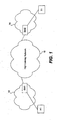
- FIG. 1 a diagram of a high latency inter-SAN network 10 connecting a Host H1 in a first SAN 12 and a target storage device T1 in a second SAN 14 is shown.
- the Host H1 is coupled to the high latency network 10 through a first switch SW1 in SAN 12.
- the target storage device T1 is coupled to the network 10 through a second switch SW2.
- the switches SW1 and SW2 are considered "border" switches since they are positioned at the interface of the network 10 and the SANs 12 and 14 respectively.
- the Host H1 and target T1 may be either directly connected to switches SW1 and SW2 or connected indirectly through any number of intermediate switches respectively.
- the network 10 may use the Internet Protocol (IP) for example over an inter-SAN link such as Gigabit Ethernet, SONET, ATM, wave division multiplexing, etc. to connect the SANs 12 and 14.
- IP Internet Protocol
- the network 10 may have a high latency relative to the SANs 12 and 14 for a variety of reasons, such as the speed of the link, congestion on the link, or distance.
- the present invention is related to a SCSI write operation that improves or reduces the time required to perform a write operation between the initiating Host H1 and target storage device such T1 over a high latency network such as the inter-SAN network 10.
- the Intelligent Ports (I-ports) of the two switches SW1 and SW2 act as an intermediary between the Host H1 and the storage device T1.
- the transfer size of a data transfer during a write operation is negotiated before any write operations are performed. Initially, the Host H1 defines (i.e., specifies the amount of data it wishes to write) the transfer size for a write command.
- the switch SW1 indicates the amount of data it is ready to receive based on (i) the data size specified in the Write command and (ii) the amount of buffer space it has.
- the I-port on SW1 responds with a Transfer Ready (Xfer) which indicates the maximum size of a data transfer.
- the I-port on the switch SW2 similarly receives the Xfer ready which defines the maximum size of the data transfer.
- the ports involved are Intelligent Ports (I-Ports) to which the initiator and target are attached.
- the I-port is typically a FC port also sometimes referred to as an Fx_Port.
- the target and the initiating Host are not directly connected to the Switches in question.
- the I-port can be either an IP-port or an I-port.
- the fast write operation is performed after the initial negotiation by the following sequence: (i) when the Host H1 generates a SCSI write command defining the target T1, the I-port of Switch SW1 traps the command; (ii) the switch SW1 forwards the command to the target; (iii) the switch SW1 also issues a Transfer Ready command to the Host H1 on behalf of or as a proxy for the target T1; (iv) the Host H1 sends data of the amount indicated by the Transfer Ready amount to the target T1 in response to the received Transfer Ready command.
- the data may sequenced or broken up into frames based on the maximum transfer unit (MTU) of the network; (v) the I-port of the switch SW1 receives the data frames and forwards it to the target T1; (vi) the previous two steps are repeated until all the data is transferred to the target; and (vii) after all the data is transferred, the switch SW1 waits for either a success or error status command from the target T1. Upon receipt, the switch SW1 forwards the status command back to the Host H1. If the target returns an error command, no attempt is made by the I-port to correct the error.
- the above sequence can be performed by switching the order of steps (ii) and (iii) as defined above.
- the I-port of the second switch SW2 operates essentially the same as switch SW1 except that it buffers the received data frames until receiving a Transfer Ready command from the target T1. Specifically, the I-port of switch SW2: (i) forwards the SCSI write command received from switch SW1 to the target; (ii) issues a Transfer Ready command to the switch SW1 as a proxy for the target T1; (iii) buffers the data frames received from the switch SW1; (iv) transfers the data frames to the target T1 when a Transfer Ready command is received from the target T1; and (v) after all the data is transferred, the switch SW2 waits for either a success or error status command from the target T1. Upon receipt, the switch SW2 forwards the status command back to switch SW1. If the target returns an error command, no attempt is made by the I-port of switch SW2 to correct the error.
- FCIDs Fibre Channel Identifiers
- a transaction between an FC host and a target is referred to as an exchange.
- OX_ID Originator Exchange Identifier
- RX_ID Receiver Exchange Identifier
- the Host relies on the OX_ID to maintain its local state and the target relies on the RX_ID to maintain its local state. In both cases, the OX_ID and RX_ID are typically 16 bits wide.
- the OX_ID and RX_ID are typically used by the initiating host and target of a transaction respectively to keep track of the ongoing transactions between the two entities.
- the switches in a SAN do not keep track of such transactions.
- the switches SW1 and SW2 are acting as intermediaries between the initiating Host and the target T1.
- the switches SW1 and SW2 therefore also use the OX_ID and RX_ID values to track exchanges between the Host H1 and the target T1.
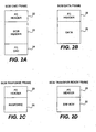
- the SCSI command frame includes a FC header field 20, a SCSI header field 22, and a FC-CRC field 24.
- the SCSI Data frame includes a FC header field 20 and a data field 26.
- the SCSI Response frame includes a FC header field 20 and a response frame 28.
- the SCSI Transfer Ready frame includes a FC header field 20 and a transfer ready (Xfr-rdy) field 30.
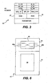
- FIG. 3 a diagram of a Fibre Channel header field 20 is shown.
- the frame includes an OX_ID field 32 and an RX_ID field 34 along with a number of other fields (which are labeled in the figure but not described herein for the sake of brevity).
- the OX_ID field 32 and the RX_ID field 34 are each 16 bits wide and are used for identifying the originating Host and target device. Since each of the above-identified SCSI frames includes a header field 20 with an OX_ID field 32 and an RX_ID field 34, the switches in a Fibre Channel network can track of a given SCSI exchange between the identified originating Host and target device.
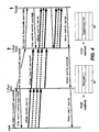
- FIG. 4 a temporal diagram is shown illustrating a SCSI write operation between the Host H1 in SAN 12 and target T1 over a inter-SAN network 10 according to the present invention.
- the direction of the arrows shows the flow of frames during the write operation.
- the vertical column from top to bottom, indicates the passage of time.
- Switches SW1 and SW2 "trap" Extended Link Service or ELS frames (state management frames) that contain the original OX_ID and RX_ID in the payload since the switches change the original values of OX_ID and RX_ID.
- ELS frames are used by the initiator H1 and target T1 to query and manage state transactions, such as ABTS and REC ELS frames.
- the RX_ID, command frame Wr and the Transfer Ready frame Xry are used by the switches SW1 and SW2 to communicate with one another regarding buffer availability and allocation for a transaction.
- the switches also use the Transfer Ready frame to grant buffer space for the transaction.
- the issued Transfer Ready command indicates to the switch SW1 that 5MB have been allocated for the write transaction.
- the switch SW1 consequently sends up to 5MB to switch SW2.
- the RX_ID value for the second command is set to 10MB, indicating that the accumulative or total allocated buffer space for the transaction is 10MBs.
- the second Transfer Ready indicates that the remaining 5MB of buffer space is now available.
- switch SW2 it is possible for switch SW2 to grant more buffer space than requested by SW1. Based on the previous example, SW2 could grant 15 MB instead of 10 MB. The remaining unutilized buffers are used for subsequent Write commands from the Host H1. For example, consider a second Write command for say 1 MB from the Host H1. With this embodiment, SW1 would send a Xfr_Rdy for 1 MB to the Host H1 and send the command to the target via SW2 as stated in paragraph 0021. When the Host H1 sends data, SW1, instead of waiting for Xrdy_Rdy to come from SW2 before sending data, now immediately starts transferring the data to SW2.
- SW2 had previously granted additional buffers to SW1 via the last Xrdy_Rdy command.
- the basic idea is that the data can be transferred from SW1 to SW2 for subsequent (after the first) write commands without waiting for a specific Xrdy_Rdy from SW2 pertaining to the subsequent write.
- a number of alternatives may take place in situations where the switch SW1 has no available buffer space.
- the Host H1 receives a busy status signal and the Host must re-try the write transaction;
- the command is placed in a pending command list.
- the switch SW1 responds to the write but only after the processing the preceding transactions on the list.
- the switch SW1 can simply forward the Write command to the target.
- the switches SW1 and SW2 are configured to set the Burst Length and Relative Offset fields in the Transfer Ready frame both to zero (0). This enables the other switches to differentiate if the Transfer Ready command was generated by the target switch or the target itself.
- the initiating switch and Host realizes that the target switch issued the Transfer Ready when both fields are set to zero (0) since the target itself would never set both to zero for a given transaction. If only one or neither of the fields are set to zero, then the initiating switch SW1 and Host realizes the Transfer Ready was generated by the target.
- the switch 40 includes a data plane 42 and a control plane 44.
- the switch includes switching logic 46 connected between two sets of ports (including the I-ports) 48a and 48b.
- the switching logic 46 is configured to route or internally switch traffic received on one port 48a to another port 48b and vice versa.
- the control plane 44 includes a processor 50 for implementing all the switching Fibre Channel functionality and protocols such as those specified in the aforementioned INCITS documents, incorporated by reference herein, the Fibre Channel adapted versions of OSPFv3, IS-IS and/or BGP4+ routing protocols, or any other protocols useful for either intra-Switch or inter-switch communication.
- the processor 50 may be implemented in a state machine, a micro-controller, hardware, firmware, programmable logic, or a combination thereof.
- the I-ports of the switch 40 negotiate with the initiating host the amount of data that can be transferred by a Write command (Wr) without waiting for a Transfer Ready command command from the target. This negotiation can takes place, for example, when the initiating Host issues a PLOGI or a PRLI to the target storage device. After the negotiation, the I-ports of the initiating and target switches SW1 and SW2 set up hardware filters to trap the any SCSI Write Commands between the specified Virtual SANs (VSANs) and initiating Host FC_ID and target device FC_ID.
- VSANs Virtual SANs
- the trap is based on a tuple defined by VSAN, Host FC_ID, target FC_ID, OX_ID and RX_ID of the frame. Whenever a command defining the specified tuple is received, the command is trapped by the switch.
- the term "trap" has used herein means the frame is not forwarded its destination, but rather is provided to the processor 50 of the switch for further processing.
- the switch SW1 forwards it to the processor 50.
- the processor 50 is responsible for forwarding the original frame on to the original destination and generating a Transfer Ready command to the initiating Host H1.
- the Transfer Ready command defines a data size determined by the existing buffer space at the switch SW1.
- the processor also defines the locally generated RX_ID which is used for all subsequent communication between the switch SW1 and the initiating Host H1.
- the data frame is received from the Host H1 at the I-port of the switch SW1, the frame is trapped.
- the processor 50 instructs the switch SW1 to transmit the data frames up to the negotiated size without waiting to receive a Transfer Ready command. Any remaining claims are buffered.
- any data frames associated with this exchange are trapped and buffered.
- the switch SW2 transfers the buffered data.
- Transfer Ready frames involving this exchange received by either switch SW1 and SW2 are also trapped and forwarded to the processor 50.
- the target switch SW2 uses the Transfer Ready frame to start the transfer of data to the target.
- the initiating switch SW1 uses the TransferReady command to transmit more data frames toward the target. In either case, the I-ports of both switches SW1 and SW2 modify the RX_ID's.
- the Fibre Channel cyclical redundancy check or CRC included in the Fibre Channel header 20 is recomputed to protect rewrite operations.
- the CRC protects FC payload and FC header from corruption while traversing various parts of a Fiber Channel SAN.
- the RX_ID and OX_ID fields are modified, the FC headers need to be protected and the CRC recomputed to protect the rewrites from any corruption.
Description
- The present invention relates generally to network communications, and more particularly, to an apparatus and method for performing fast Fibre Channel write operations over relatively high latency networks.
- With the increasing popularity of Internet commerce and network centric computing, businesses and other organizations are becoming more and more reliant on information. To handle all of this data, storage area networks or SANs have become very popular. A SAN typically includes a number of storage devices, a plurality of Hosts, and a number of Switches arranged in a Switching Fabric that connects the storage devices and the Hosts.
- Most SANs rely on the Fibre Channel protocol for communication within the Fabric. For a detailed explanation of the Fibre Channel protocol and Fibre Channel Switching Fabrics and Services, see the Fibre Channel Framing and Signaling Standard, Rev 1.90, International Committee for Information Technology Standards (INCITS), April 9, 2003, and the Fibre Channel Switch Fabric - 2, Rev. 5.4, INCITS, June 26, 2001, and the Fibre Channel Generic Services - 3, Rev. 7.01, INCITS, November 28, 2000.
- The infrastructure of many networks often includes multiple types of link level transports. For example, the communication network of an international corporation may have local SANs in their New York, Silicon Valley and Tokyo offices respectively. However, since maintaining a SAN across long distances is expensive, the organization may rely on the Internet Protocol (IP) over another inter-SAN link such as Gigabit Ethernet, SONET, ATM, wave division multiplexing, etc. to connect the SANs.
- Within a typical SAN with Fibre Channel Inter-Switch Link (ISLs), the access time between a Host and a storage device (i.e., a target) is typically very fast. The speed of a Fibre Channel link is such that the performance or access time across multiple switches in close to the ideal, i.e., the Host and the target device are attached to the same switch. In other words, even if multiple Switches need to be spanned to complete the access, the speed of the individual Switches is so fast that the latency time is typically very small. In a write operation for example, packets of data can be transferred across the switches of the SAN without delay as the latency between the ISLs is very small.
- In situations with a high latency inter-SAN link, however, the access time of a write operation between a Host in one SAN and a storage device in a remote SAN will suffer or deteriorate. The latency may result from the speed of the link, the distance between the Host and target, congestion on the inter-SAN link, etc. For example, when IP is used to connect two Fibre Channel SANs, the latency across the IP portion of the network is typically slow relative to an access within the SANs.
- With a SCSI write command, the Host will issue a write (Wr) command defining a certain amount of data to be written. The command travels across the network, from switch to switch, until it reaches the target. In reply, the target responds with a Xfer ready command which defines the amount of data which the target may accept. When the Host receives the Xfer ready command, it transfers the data to be written in units up to the maximum transfer unit (MTU) of the network. In most Fibre Channel SANS, the MTU is approximately 2K bytes per transfer. Thus if the amount of data to be written is 8K bytes, then a total of four transfers are required. When in this case all four data transfers are received, the target generates a status success command. If for some reason the Host does not receive the status command after a predetermined period of time, it is assumed that a problem with the write operation occurred. The Host may subsequently issue another write command.
- The time required to complete a SCSI write operation can be significant over a high latency inter-SAN network. A significant amount of time may lapse between the time the initial Wr command is issued and the Xfer ready is received by the Host due to the slow performance of the high latency inter-SAN network. During this time, the Host is idle and must wait until before issuing the data transfer commands to transfer the data to the Host. The target is also idle until it receives the data from the initiating Host. In other words, the initiating Host is idle until it receives the Xfer ready and the target is idle after issuing the Xfer ready until it receives the data.
-
US 2003/185154 discloses a flow control mechanism implemented in a switch device to manage buffer and system level resources using a scheduler to control the amount of data requested from a local SAN fabric. Switches monitor each individual SCSI task, and are configured to apply flow control measures to each active session when buffering resources become scarce.US 2003/172149 discloses implementing storage virtualization on a network device of a storage area network. An apparatus and method improving the performance of a SCSI write over a relatively high latency network is therefore needed. - To achieve the foregoing and other objectives and in accordance with the purpose of the present invention, an apparatus and method to improve the performance of a SCSI write over a high latency network is provided. The apparatus includes a first Switch close to the initiator in a first SAN and a second Switch close to the target in a second SAN. In various embodiments, the two Switches are border switches connecting their respective SANs to a relatively high latency network between the two SANs. In addition, the initiator can be either directly connected or indirectly connected to the first Switch in the first SAN. The target can also be either directly or indirectly connected to the second Switch in the second SAN. During operation, the method includes the first Switch sending Transfer Ready (Xfr_rdy) frame (s) based on buffer availability to the initiating Host in response to a SCSI Write command from the Host directed to the target. The first and second Switches then coordinate with one another by sending Transfer Ready commands to each other independent of the target's knowledge. The second switch buffers the data received from the Host until the target indicates it is ready to receive the data. Since the Switches send frames to the initiating Host independent of the target, the Switches manipulate the OX_ID and RX_ID fields in the Fibre Channel header of the various commands associated with the SCSI Write. The OX_ID and RX_ID fields are manipulated so as to trap the commands and so that the Switches can keep track of the various commands associated with the SCSI write.
- The features of the present invention may best be understood by reference to the following description of the presently preferred embodiments together with the accompanying drawings.
-
Figure 1 is a diagram of a high latency network connecting a Host in a first SAN and a storage device in a second SAN. -
Figures 2A-2D are SCSI Command, Data, Response and Transfer Ready frames respectively. -
Figure 3 is a diagram of a Fibre Channel header. -
Figure 4 is a temporal diagram illustrating a SCSI fast write operation over a high latency network according to one embodiment of the present invention. -
Figure 5 is a temporal diagram illustrating a SCSI fast write operation over a high latency network according to another embodiment of the present invention. -
Figure 6 is a block diagram of a switch according to the present invention. - Like reference numbers refer to like elements in the figures.
- Referring to
Figure 1 , a diagram of a high latency inter-SANnetwork 10 connecting a Host H1 in afirst SAN 12 and a target storage device T1 in a second SAN 14 is shown. The Host H1 is coupled to thehigh latency network 10 through a first switch SW1 in SAN 12. The target storage device T1 is coupled to thenetwork 10 through a second switch SW2. The switches SW1 and SW2 are considered "border" switches since they are positioned at the interface of thenetwork 10 and theSANs 12 and 14 respectively. According to various embodiments, the Host H1 and target T1 may be either directly connected to switches SW1 and SW2 or connected indirectly through any number of intermediate switches respectively. Thenetwork 10 may use the Internet Protocol (IP) for example over an inter-SAN link such as Gigabit Ethernet, SONET, ATM, wave division multiplexing, etc. to connect theSANs 12 and 14. Again, thenetwork 10 may have a high latency relative to theSANs 12 and 14 for a variety of reasons, such as the speed of the link, congestion on the link, or distance. - The present invention is related to a SCSI write operation that improves or reduces the time required to perform a write operation between the initiating Host H1 and target storage device such T1 over a high latency network such as the
inter-SAN network 10. The Intelligent Ports (I-ports) of the two switches SW1 and SW2 act as an intermediary between the Host H1 and the storage device T1. The transfer size of a data transfer during a write operation is negotiated before any write operations are performed. Initially, the Host H1 defines (i.e., specifies the amount of data it wishes to write) the transfer size for a write command. The switch SW1 indicates the amount of data it is ready to receive based on (i) the data size specified in the Write command and (ii) the amount of buffer space it has. The I-port on SW1 responds with a Transfer Ready (Xfer) which indicates the maximum size of a data transfer. The I-port on the switch SW2 similarly receives the Xfer ready which defines the maximum size of the data transfer. In the aforementioned embodiment, the ports involved are Intelligent Ports (I-Ports) to which the initiator and target are attached. In such a case, the I-port is typically a FC port also sometimes referred to as an Fx_Port. In an alternative embodiment, the target and the initiating Host are not directly connected to the Switches in question. In such a case, the I-port can be either an IP-port or an I-port. - In general, the fast write operation is performed after the initial negotiation by the following sequence: (i) when the Host H1 generates a SCSI write command defining the target T1, the I-port of Switch SW1 traps the command; (ii) the switch SW1 forwards the command to the target; (iii) the switch SW1 also issues a Transfer Ready command to the Host H1 on behalf of or as a proxy for the target T1; (iv) the Host H1 sends data of the amount indicated by the Transfer Ready amount to the target T1 in response to the received Transfer Ready command. The data may sequenced or broken up into frames based on the maximum transfer unit (MTU) of the network; (v) the I-port of the switch SW1 receives the data frames and forwards it to the target T1; (vi) the previous two steps are repeated until all the data is transferred to the target; and (vii) after all the data is transferred, the switch SW1 waits for either a success or error status command from the target T1. Upon receipt, the switch SW1 forwards the status command back to the Host H1. If the target returns an error command, no attempt is made by the I-port to correct the error. In should be noted that in an alternative embodiment, the above sequence can be performed by switching the order of steps (ii) and (iii) as defined above.
- The I-port of the second switch SW2 operates essentially the same as switch SW1 except that it buffers the received data frames until receiving a Transfer Ready command from the target T1. Specifically, the I-port of switch SW2: (i) forwards the SCSI write command received from switch SW1 to the target; (ii) issues a Transfer Ready command to the switch SW1 as a proxy for the target T1; (iii) buffers the data frames received from the switch SW1; (iv) transfers the data frames to the target T1 when a Transfer Ready command is received from the target T1; and (v) after all the data is transferred, the switch SW2 waits for either a success or error status command from the target T1. Upon receipt, the switch SW2 forwards the status command back to switch SW1. If the target returns an error command, no attempt is made by the I-port of switch SW2 to correct the error.
- To identify an FC device, Fibre Channel Identifiers (FCIDs) are used. A transaction between an FC host and a target is referred to as an exchange. In a typical Fibre Channel network, there are many Hosts and targets. Each Host may initiate many read and/or write operations. For the hosts and targets within a network to keep track of the various transactions between each other, two fields are available in the Fibre Channel header for all SCSI Command, Data, Response, and Transfer Ready frames. The first field is called the Originator Exchange Identifier or OX_ID. The second field is called the Receiver Exchange Identifier or RX_ID. The Host relies on the OX_ID to maintain its local state and the target relies on the RX_ID to maintain its local state. In both cases, the OX_ID and RX_ID are typically 16 bits wide.
- The OX_ID and RX_ID are typically used by the initiating host and target of a transaction respectively to keep track of the ongoing transactions between the two entities. In general, the switches in a SAN do not keep track of such transactions. With the present invention, however, the switches SW1 and SW2 are acting as intermediaries between the initiating Host and the target T1. The switches SW1 and SW2 therefore also use the OX_ID and RX_ID values to track exchanges between the Host H1 and the target T1.
- Referring to
Figures 2A-2D , SCSI Command, Data, Response and Transfer Ready frames are shown respectively. As illustrated inFigure 2A , the SCSI command frame includes aFC header field 20, aSCSI header field 22, and a FC-CRC field 24. As illustrated inFigure 2B , the SCSI Data frame includes aFC header field 20 and adata field 26. As illustrated inFigure 2C , the SCSI Response frame includes aFC header field 20 and aresponse frame 28. As illustrated inFigure 2C , the SCSI Transfer Ready frame includes aFC header field 20 and a transfer ready (Xfr-rdy)field 30. - Referring to
Figure 3 , a diagram of a FibreChannel header field 20 is shown. The frame includes anOX_ID field 32 and anRX_ID field 34 along with a number of other fields (which are labeled in the figure but not described herein for the sake of brevity). As previously noted, theOX_ID field 32 and theRX_ID field 34 are each 16 bits wide and are used for identifying the originating Host and target device. Since each of the above-identified SCSI frames includes aheader field 20 with anOX_ID field 32 and anRX_ID field 34, the switches in a Fibre Channel network can track of a given SCSI exchange between the identified originating Host and target device. - Referring to
Figure 4 , a temporal diagram is shown illustrating a SCSI write operation between the Host H1 inSAN 12 and target T1 over ainter-SAN network 10 according to the present invention. In the diagram, the direction of the arrows shows the flow of frames during the write operation. The vertical column, from top to bottom, indicates the passage of time. When a SCSI write operation is performed between the Host H1 and the target T1, the following sequence of events occur: - a. Host H1 initiates the fast write operation by issuing a SCSI write command (Wr: OX_ID = 1 RX_ID = Oxffff, Size = 10MB). The command defines the originating exchange identifier as 1 (OX_ID = 1). The receiving exchange identifier RX_ID, however, is "uninitialized" and is set to a default value of "Oxffff". The write command also specifies the amount of data to be written, which in this example, is 10 megabytes (MB).
- b. Upon receipt, the switch SW1 initializes the receiving exchange identifier RX_ID. In this example, the RX_ID is initialized to 10. The switch SW1 then determines if it has sufficient storage space to buffer the data. Assuming that it does, the switch SW1 sends a Transfer Ready command (Xrdy: OX_ID = 1, RX_ID = 10, Size = 10 MG) to the Host H1. All subsequent commands or frames between the Host and switch SW1, and vice versa, associated with this SCSI write operation define the OX_ID = 1 and the RX_ID =10. If the switch SW1 does not have sufficient buffer space, then a SCSI busy status is returned to the host H1, mimicking the behavior of a target when the target does not have resources for a new exchange.
- c. The initiating switch SW1 uses the OX_ID to keep track of the transaction. Consequently, the switch SW1 changes the OX_ID provided by the initiating Host H1. In this example, the switch SW1 changes the OX_ID value to 10. The switch SW1 then forwards the write command to the target T1 with the RX_ID value remaining uninitialized (Wr: OX_ID = 10, RX_ID = Oxffff, Size = 10MB). All communication between the first switch SW1 and the target involving this write operation thereafter includes an OX_ID = 10 and RX_ID = Oxffff. The initiating switch SW1 uses the OX_ID value as a handle or pointer into a session table 36 maintained at switch SW1. The table includes an entry that includes information regarding the session that is accessed by the RX_ID handle.
- d. When the second switch SW2 receives the write command, it initializes an exchange identifier entry in the sessions table 38 and it immediately forwards the command to the target T1 provided the switch SW2 has sufficient buffer space. If it does not have sufficient space, then a SCSI busy status is sent back to the initiating host H1.
- e. If the target T1 is ready to receive the data, it sends a Transfer Ready command back to the switch SW2. According to one embodiment, the target designates an RX_ID value for the write transaction. In this case, the target designates an RX_ID value of 50. The Transfer Ready command received by the switch SW2 therefore appears as (Xrdy: OX_ID = 10) RX_ID = 50, size = 10MB). All subsequent communications between the switch SW2 and the target T1 involving this transaction include OX_ID value of 10 and an RX_ID value of 50. The switch SW2 also maintains a sessions ID table 38. Upon receipt of the Transfer Ready command, the switch SW2 inserts a RX_ID = 50 value into the table. The switch SW2 uses the modified OX_ID = 10 value as a handle or pointer into a sessions ID table 38. The target switch SW2 uses the OX_ID value as a handle or pointer for this session between in session table 38. The table includes an entry that includes the information regarding the session such as the target RX_ID.
- f. If the second switch SW2 receives the data frames (Wdata: OX_ID = 10, RX_ID = Oxffff) from the first switch SW1 before the Transfer Ready command from the target T1, then the second switch SW2 buffers the data. When the Transfer Ready command is received, the data frame(s) are then forwarded to the target T1. On the other hand, if the data frames arrive after the Transfer Ready command, the data frames are immediately forwarded to the target T1.
- g. When all the data has been transferred, the target T1 generates a Status command (Status: OX_ID=10, RX_ID=50). The second switch SW2 modifies the RX_ID = Oxffff and forwards the status command to the switch SW1. The switch SW1 in turn changes the RX_ID = 10 and sends the status command to the Host H1 to complete the fast write operation. It should be noted that in the event the target T1 provides a transfer size less than the requested size, the I-port on the switch SW2 waits for successive Transfer Ready commands until the requested size is met1.
- It also should be noted that the Switches SW1 and SW2 "trap" Extended Link Service or ELS frames (state management frames) that contain the original OX_ID and RX_ID in the payload since the switches change the original values of OX_ID and RX_ID. ELS frames are used by the initiator H1 and target T1 to query and manage state transactions, such as ABTS and REC ELS frames.
- Referring to
Figure 5 , an alternative embodiment of the present invention is shown. With this embodiment, the RX_ID, command frame Wr and the Transfer Ready frame Xry are used by the switches SW1 and SW2 to communicate with one another regarding buffer availability and allocation for a transaction. InFigure 5 for example, the switch SW1 uses the RX_ID = 10 value in the Wr command (Wr: OXID = 10, RXID = 10 MB, size = 10 MB) to (i) specify the amount of buffer space needed for the write transaction; and (ii) use the command frame to request the needed buffer space. The switches also use the Transfer Ready frame to grant buffer space for the transaction. In this example, the switch SW2 generates a first Transfer Ready command with 5MB encoded in the RX_ID value (Xrdy: OX_ID = 1, RX 5 MB). The issued Transfer Ready command indicates to the switch SW1 that 5MB have been allocated for the write transaction. The switch SW1 consequently sends up to 5MB to switch SW2. When a second 5MB of buffer space becomes available, a second Transfer Ready command is issued (Xrdy: OX_ID = 1, RX_ID = 10, Size = 10 MB). Note, the RX_ID value for the second command is set to 10MB, indicating that the accumulative or total allocated buffer space for the transaction is 10MBs. The second Transfer Ready indicates that the remaining 5MB of buffer space is now available. - In an alternative embodiment, it is possible for switch SW2 to grant more buffer space than requested by SW1. Based on the previous example, SW2 could grant 15 MB instead of 10 MB. The remaining unutilized buffers are used for subsequent Write commands from the Host H1. For example, consider a second Write command for
say 1 MB from the Host H1. With this embodiment, SW1 would send a Xfr_Rdy for 1 MB to the Host H1 and send the command to the target via SW2 as stated in paragraph 0021. When the Host H1 sends data, SW1, instead of waiting for Xrdy_Rdy to come from SW2 before sending data, now immediately starts transferring the data to SW2. It can do this because SW2 had previously granted additional buffers to SW1 via the last Xrdy_Rdy command. The basic idea is that the data can be transferred from SW1 to SW2 for subsequent (after the first) write commands without waiting for a specific Xrdy_Rdy from SW2 pertaining to the subsequent write. - In various embodiments of the invention, a number of alternatives may take place in situations where the switch SW1 has no available buffer space. In one embodiment, the Host H1 receives a busy status signal and the Host must re-try the write transaction; In a second embodiment, the command is placed in a pending command list. Eventually, the switch SW1 responds to the write but only after the processing the preceding transactions on the list. In yet another embodiment, the switch SW1 can simply forward the Write command to the target.
- In yet another embodiment, the switches SW1 and SW2 are configured to set the Burst Length and Relative Offset fields in the Transfer Ready frame both to zero (0). This enables the other switches to differentiate if the Transfer Ready command was generated by the target switch or the target itself. The initiating switch and Host realizes that the target switch issued the Transfer Ready when both fields are set to zero (0) since the target itself would never set both to zero for a given transaction. If only one or neither of the fields are set to zero, then the initiating switch SW1 and Host realizes the Transfer Ready was generated by the target.
- In data networks, data frames are lost on occasion. In various embodiments of the present invention, an one of a number of different buffer credit recovery schemes may be used.
- Referring to
Figure 6 , a block diagram of a switch SW according to the present invention is shown. Theswitch 40 includes adata plane 42 and acontrol plane 44. In thedata plane 42, the switch includes switchinglogic 46 connected between two sets of ports (including the I-ports) 48a and 48b. The switchinglogic 46 is configured to route or internally switch traffic received on oneport 48a to anotherport 48b and vice versa. Thecontrol plane 44 includes aprocessor 50 for implementing all the switching Fibre Channel functionality and protocols such as those specified in the aforementioned INCITS documents, incorporated by reference herein, the Fibre Channel adapted versions of OSPFv3, IS-IS and/or BGP4+ routing protocols, or any other protocols useful for either intra-Switch or inter-switch communication. In various embodiments of the invention, theprocessor 50 may be implemented in a state machine, a micro-controller, hardware, firmware, programmable logic, or a combination thereof. As previously noted, the I-ports of theswitch 40 negotiate with the initiating host the amount of data that can be transferred by a Write command (Wr) without waiting for a Transfer Ready command command from the target. This negotiation can takes place, for example, when the initiating Host issues a PLOGI or a PRLI to the target storage device. After the negotiation, the I-ports of the initiating and target switches SW1 and SW2 set up hardware filters to trap the any SCSI Write Commands between the specified Virtual SANs (VSANs) and initiating Host FC_ID and target device FC_ID. The trap is based on a tuple defined by VSAN, Host FC_ID, target FC_ID, OX_ID and RX_ID of the frame. Whenever a command defining the specified tuple is received, the command is trapped by the switch. The term "trap" has used herein means the frame is not forwarded its destination, but rather is provided to theprocessor 50 of the switch for further processing. - When a Write command is received at the initiating switch SW1 that specifies a tuple to be trapped, the switch SW1 forwards it to the
processor 50. In reply, theprocessor 50 is responsible for forwarding the original frame on to the original destination and generating a Transfer Ready command to the initiating Host H1. The Transfer Ready command defines a data size determined by the existing buffer space at the switch SW1. The processor also defines the locally generated RX_ID which is used for all subsequent communication between the switch SW1 and the initiating Host H1. When the data frame is received from the Host H1 at the I-port of the switch SW1, the frame is trapped. Theprocessor 50 in turn instructs the switch SW1 to transmit the data frames up to the negotiated size without waiting to receive a Transfer Ready command. Any remaining claims are buffered. Similarly, at the I-port of the switch SW2, any data frames associated with this exchange are trapped and buffered. When a Transfer Ready is received from the target T1, the switch SW2 transfers the buffered data. - Transfer Ready frames involving this exchange received by either switch SW1 and SW2 are also trapped and forwarded to the
processor 50. The target switch SW2 uses the Transfer Ready frame to start the transfer of data to the target. The initiating switch SW1 on the other hand, uses the TransferReady command to transmit more data frames toward the target. In either case, the I-ports of both switches SW1 and SW2 modify the RX_ID's. - According to one embodiment, the Fibre Channel cyclical redundancy check or CRC included in the
Fibre Channel header 20 is recomputed to protect rewrite operations. The CRC protects FC payload and FC header from corruption while traversing various parts of a Fiber Channel SAN. With the present invention, the RX_ID and OX_ID fields are modified, the FC headers need to be protected and the CRC recomputed to protect the rewrites from any corruption.
Claims (22)
- An apparatus, comprising: a Switch, the Switch including:a port configured to receive a write command frame having a header (20) comprising an originator exchange identifier, OX_ID (32), a receiver exchange identifier, RX_ID (34), a Host_ID identifier identifying an initiating Host (H1) and a target_ID identifier identifying a target (T1);a trapping mechanism configured to trap the write command frame if the write command frame includes a predetermined Host_ID and a predetermined target_ID; anda processor configured to process the trapped write command by modifying the OX_ID (32) of the write command frame header to include a new value of the OX_ID (32) before sending the write command frame to the target (T1);wherein the processor is further configured to generate a transfer ready command frame by initializing an RX_ID (34) of the transfer command frame by assigning a value to the RX_ID (34) and to send the transfer ready command frame to the initiating Host (H1) before receiving a transfer ready command frame from the target (T1).
- The apparatus of claim 1, wherein the Switch is an initiating Switch coupled to the Host in a first SAN.
- The apparatus of claim 2, wherein the processor of the initiating Switch is further configured to modify the write command frame before forwarding the write command frame to the target.
- The apparatus of claim 2, wherein the initiating Switch uses the initialized RX_ID value as a handle for accessing information pertaining to the write command session in a sessions ID table.
- The apparatus of claim 2, wherein the processor of the initiating Switch is further configured to issue a Transfer Ready command to the Host.
- The apparatus of claim 4, wherein the initiating Switch is further configured to use the initialized RX_ID value as the RX_ID for all communication related to the write command frame between the initiating Switch and the Host.
- The apparatus of claim 4, wherein the initiating Switch is further configured to use the new OX_ID value as the OX_ID in all communications between the initiating Switch and the target.
- The apparatus of claim 2, wherein the initiating Switch is further configured to transfer additional data frames to the target when the initiating Switch receives a Transfer Ready command associated with the write command frame from the target.
- The apparatus of claim 1, wherein the Switch is a target Switch coupled to the target.
- The apparatus of claim 9, wherein the target Switch forwards the write command to the target.
- The apparatus of claim 10, wherein the target Switch forwards data frames associated with the write command frame to the target after receiving a Transfer Ready command from the target.
- The apparatus of claim 11, wherein the target Switch is further configured to buffer the data frames prior to receipt of the Transfer Ready command.
- The apparatus of claim 11, wherein the target Switch is further configured to maintain a sessions ID table and to use the OX_ID of the write command frame as an index to the session corresponding to the write command.
- The apparatus of claim 9, wherein the target Switch is further configured to modify the RX_ID value for all communication related to the write command frame between the target Switch and the Host.
- The apparatus of claim 14, wherein the target Switch is further configured to modify the OX_ID value in communications between the target Switch and the target.
- The apparatus of claim 1 wherein the Switch is further configured to use the RX_ID value of trapped write command frames to specify the amount of buffer space needed for the write command frame and use the write command frame to request the needed buffer space.
- The apparatus of claim 16, wherein the Switch is further configured to use the RX_ID value of trapped write command frames to specify the amount of buffer space larger than needed for the write command frame and use the additional buffer space for subsequent write command frames so that the Switch need not wait for a Transfer Ready command to transfer data related to the subsequent write command frame.
- The apparatus of claim 1, wherein the Switch is further configured to, in the event the Switch does not have sufficient buffer space for the write command frame, to either:(i) generate a busy status signal to the initiating Host;(ii) place the write command frame on a pending wait list; or(iii) forward the write command frame to the target.
- A system comprising:a first SAN including a first Switch comprising the apparatus of claim 1;a second SAN including a second Switch; andan inter-SAN network connecting the first SAN and the second SAN.
- A method comprising:receiving a write command frame at a Switch, the write command frame having a header (20)comprising an originator exchange identifier, OX_ID (32), a receiver exchange identifier, RX_ID (34), a Host_ID identifier identifying an initiating Host (H1)and a target_ID identifier identifying a target (T1);trapping a write command frame if the write command frame includes a predetermined Host_ID and a predetermined target_ID at the Switch;configuring the Switch to process the trapped write command by modifying the OX_ID (32) of the write command frame header to include a new value of the OX_ID (32) before forwarding the write command frame to the target (T1);configuring the Switch to initialize the RX_ID (34) of the write command frame by assigning a value to the RX_ID (34); andconfiguring the Switch to generate a Transfer Ready command frame including the initialized RX_ID value to the initiating Host as a proxy for the target (T1) before receiving a transfer ready command frame from the target (T1).
- The method of claim 20, further comprising configuring the Switch to forward data frames associated with the write command frame received in response to the Transfer Ready command to the target.
- The method of claim 21, further comprising:receiving the write command frame forwarded to the target by the Switch at a second Switch;configuring the second Switch to forward the write command frame to the target; andeither:buffering the data frames forwarded to the target by the Switch until a Transfer Ready command is received from the target; orforwarding the data frames from the Switch to the target if the Transfer Ready command has already been received from the initiating Host.
Applications Claiming Priority (2)
| Application Number | Priority Date | Filing Date | Title |
|---|---|---|---|
| US10/726,269 US7934023B2 (en) | 2003-12-01 | 2003-12-01 | Apparatus and method for performing fast fibre channel write operations over relatively high latency networks |
| PCT/US2004/039904 WO2005055497A2 (en) | 2003-12-01 | 2004-11-29 | Apparatus and method for performing fast fibre channel write operations over relatively high latency networks |
Publications (3)
| Publication Number | Publication Date |
|---|---|
| EP1690359A2 EP1690359A2 (en) | 2006-08-16 |
| EP1690359A4 EP1690359A4 (en) | 2013-12-04 |
| EP1690359B1 true EP1690359B1 (en) | 2015-09-02 |
Family
ID=34620484
Family Applications (1)
| Application Number | Title | Priority Date | Filing Date |
|---|---|---|---|
| EP04817921.2A Active EP1690359B1 (en) | 2003-12-01 | 2004-11-29 | Apparatus and method for performing fast fibre channel write operations over relatively high latency networks |
Country Status (6)
| Country | Link |
|---|---|
| US (1) | US7934023B2 (en) |
| EP (1) | EP1690359B1 (en) |
| CN (1) | CN1918925B (en) |
| AU (1) | AU2004311001B2 (en) |
| CA (1) | CA2546783C (en) |
| WO (1) | WO2005055497A2 (en) |
Families Citing this family (56)
| Publication number | Priority date | Publication date | Assignee | Title |
|---|---|---|---|---|
| US7548975B2 (en) * | 2002-01-09 | 2009-06-16 | Cisco Technology, Inc. | Methods and apparatus for implementing virtualization of storage within a storage area network through a virtual enclosure |
| US8805918B1 (en) | 2002-09-11 | 2014-08-12 | Cisco Technology, Inc. | Methods and apparatus for implementing exchange management for virtualization of storage within a storage area network |
| US7397768B1 (en) | 2002-09-11 | 2008-07-08 | Qlogic, Corporation | Zone management in a multi-module fibre channel switch |
| US7388843B2 (en) * | 2003-07-16 | 2008-06-17 | Qlogic, Corporation | Method and apparatus for testing loop pathway integrity in a fibre channel arbitrated loop |
| US7355966B2 (en) * | 2003-07-16 | 2008-04-08 | Qlogic, Corporation | Method and system for minimizing disruption in common-access networks |
| US7463646B2 (en) * | 2003-07-16 | 2008-12-09 | Qlogic Corporation | Method and system for fibre channel arbitrated loop acceleration |
| US7792115B2 (en) | 2003-07-21 | 2010-09-07 | Qlogic, Corporation | Method and system for routing and filtering network data packets in fibre channel systems |
| US7894348B2 (en) | 2003-07-21 | 2011-02-22 | Qlogic, Corporation | Method and system for congestion control in a fibre channel switch |
| US7684401B2 (en) | 2003-07-21 | 2010-03-23 | Qlogic, Corporation | Method and system for using extended fabric features with fibre channel switch elements |
| US7646767B2 (en) | 2003-07-21 | 2010-01-12 | Qlogic, Corporation | Method and system for programmable data dependant network routing |
| US7934023B2 (en) | 2003-12-01 | 2011-04-26 | Cisco Technology, Inc. | Apparatus and method for performing fast fibre channel write operations over relatively high latency networks |
| US7930377B2 (en) | 2004-04-23 | 2011-04-19 | Qlogic, Corporation | Method and system for using boot servers in networks |
| US7340167B2 (en) * | 2004-04-23 | 2008-03-04 | Qlogic, Corporation | Fibre channel transparent switch for mixed switch fabrics |
| US7404020B2 (en) * | 2004-07-20 | 2008-07-22 | Qlogic, Corporation | Integrated fibre channel fabric controller |
| US8295299B2 (en) | 2004-10-01 | 2012-10-23 | Qlogic, Corporation | High speed fibre channel switch element |
| US20060126520A1 (en) * | 2004-12-15 | 2006-06-15 | Cisco Technology, Inc. | Tape acceleration |
| US7672323B2 (en) * | 2005-01-14 | 2010-03-02 | Cisco Technology, Inc. | Dynamic and intelligent buffer management for SAN extension |
| US7870317B2 (en) * | 2005-04-29 | 2011-01-11 | Network Appliance, Inc. | Storage processor for handling disparate requests to transmit in a storage appliance |
| US8069270B1 (en) | 2005-09-06 | 2011-11-29 | Cisco Technology, Inc. | Accelerated tape backup restoration |
| US8266431B2 (en) * | 2005-10-31 | 2012-09-11 | Cisco Technology, Inc. | Method and apparatus for performing encryption of data at rest at a port of a network device |
| GB2433395A (en) * | 2005-12-15 | 2007-06-20 | Bridgeworks Ltd | Cache module in a bridge device operating in auto-response mode |
| US8176217B2 (en) * | 2005-12-20 | 2012-05-08 | Lsi Corporation | System and method for implementing a storage protocol with initiator controlled data transfer |
| US8971325B1 (en) * | 2006-06-30 | 2015-03-03 | Marvell International Ltd. | Policy system and method for a switching device |
| US8055726B1 (en) * | 2006-10-31 | 2011-11-08 | Qlogic, Corporation | Method and system for writing network data |
| US8464074B1 (en) | 2008-05-30 | 2013-06-11 | Cisco Technology, Inc. | Storage media encryption with write acceleration |
| CN101917231B (en) * | 2010-08-27 | 2013-10-09 | 华为技术有限公司 | Data caching method of fibre channel switch |
| US20120054850A1 (en) * | 2010-08-31 | 2012-03-01 | Cisco Technology, Inc. | Proxying for Clusters of Fiber Channel Servers to Reduce Configuration Requirements for Fiber Channel Storage Arrays |
| US9185018B2 (en) * | 2010-10-22 | 2015-11-10 | Brocade Communications Systems, Inc. | Path diagnosis in communication networks |
| WO2013049338A1 (en) * | 2011-09-28 | 2013-04-04 | Marvell World Trade Ltd. | Systems and methods for creating bidirectional communication channels using block devices |
| US9164947B1 (en) * | 2012-12-07 | 2015-10-20 | Qlogic, Corporation | Method and system for inserting cookies in I/O commands |
| US9195626B2 (en) * | 2013-01-29 | 2015-11-24 | Emulex Corporation | Reducing write I/O latency using asynchronous Fibre Channel exchange |
| US10209906B2 (en) | 2013-10-31 | 2019-02-19 | Hewlett Packard Enterprises Development LP | Target port processing of a data transfer |
| WO2015126429A1 (en) | 2014-02-24 | 2015-08-27 | Hewlett-Packard Development Company, L.P. | Repurposable buffers for target port processing of a data transfer |
| US9853873B2 (en) | 2015-01-10 | 2017-12-26 | Cisco Technology, Inc. | Diagnosis and throughput measurement of fibre channel ports in a storage area network environment |
| US9900250B2 (en) | 2015-03-26 | 2018-02-20 | Cisco Technology, Inc. | Scalable handling of BGP route information in VXLAN with EVPN control plane |
| US10222986B2 (en) | 2015-05-15 | 2019-03-05 | Cisco Technology, Inc. | Tenant-level sharding of disks with tenant-specific storage modules to enable policies per tenant in a distributed storage system |
| US9864716B2 (en) | 2015-05-20 | 2018-01-09 | International Business Machines Corporation | Receiving buffer credits by a plurality of channels of one or more host computational devices for transmitting data to a control unit |
| US10061734B2 (en) | 2015-05-20 | 2018-08-28 | International Business Machines Corporation | Adjustment of buffer credits and other parameters in a startup phase of communications between a plurality of channels and a control unit |
| US9892065B2 (en) | 2015-05-20 | 2018-02-13 | International Business Machines Corporation | Adjustments of buffer credits for optimizing the number of retry operations and transfer ready operations |
| US11588783B2 (en) | 2015-06-10 | 2023-02-21 | Cisco Technology, Inc. | Techniques for implementing IPV6-based distributed storage space |
| US10778765B2 (en) | 2015-07-15 | 2020-09-15 | Cisco Technology, Inc. | Bid/ask protocol in scale-out NVMe storage |
| US9892075B2 (en) | 2015-12-10 | 2018-02-13 | Cisco Technology, Inc. | Policy driven storage in a microserver computing environment |
| US10140172B2 (en) | 2016-05-18 | 2018-11-27 | Cisco Technology, Inc. | Network-aware storage repairs |
| US20170351639A1 (en) | 2016-06-06 | 2017-12-07 | Cisco Technology, Inc. | Remote memory access using memory mapped addressing among multiple compute nodes |
| US10664169B2 (en) | 2016-06-24 | 2020-05-26 | Cisco Technology, Inc. | Performance of object storage system by reconfiguring storage devices based on latency that includes identifying a number of fragments that has a particular storage device as its primary storage device and another number of fragments that has said particular storage device as its replica storage device |
| US11563695B2 (en) | 2016-08-29 | 2023-01-24 | Cisco Technology, Inc. | Queue protection using a shared global memory reserve |
| US10545914B2 (en) | 2017-01-17 | 2020-01-28 | Cisco Technology, Inc. | Distributed object storage |
| US10243823B1 (en) | 2017-02-24 | 2019-03-26 | Cisco Technology, Inc. | Techniques for using frame deep loopback capabilities for extended link diagnostics in fibre channel storage area networks |
| US10713203B2 (en) | 2017-02-28 | 2020-07-14 | Cisco Technology, Inc. | Dynamic partition of PCIe disk arrays based on software configuration / policy distribution |
| US10254991B2 (en) | 2017-03-06 | 2019-04-09 | Cisco Technology, Inc. | Storage area network based extended I/O metrics computation for deep insight into application performance |
| US10303534B2 (en) | 2017-07-20 | 2019-05-28 | Cisco Technology, Inc. | System and method for self-healing of application centric infrastructure fabric memory |
| US10404596B2 (en) | 2017-10-03 | 2019-09-03 | Cisco Technology, Inc. | Dynamic route profile storage in a hardware trie routing table |
| US10942666B2 (en) | 2017-10-13 | 2021-03-09 | Cisco Technology, Inc. | Using network device replication in distributed storage clusters |
| US10310760B1 (en) | 2018-05-21 | 2019-06-04 | Pure Storage, Inc. | Layering communication fabric protocols |
| US11954220B2 (en) | 2018-05-21 | 2024-04-09 | Pure Storage, Inc. | Data protection for container storage |
| CN113934672B (en) * | 2021-12-14 | 2022-03-01 | 北京国科天迅科技有限公司 | Network equipment management method, system, device, computer equipment and storage medium |
Family Cites Families (75)
| Publication number | Priority date | Publication date | Assignee | Title |
|---|---|---|---|---|
| JPS648433A (en) | 1987-07-01 | 1989-01-12 | Hitachi Ltd | Multiplexing system for storage device |
| JPH02144718A (en) | 1988-11-28 | 1990-06-04 | Fujitsu Ltd | Control system for dual port interface |
| JP3019619B2 (en) | 1992-08-27 | 2000-03-13 | 日本電気株式会社 | Magnetic disk drive and method of controlling magnetic disk drive |
| JP3561002B2 (en) | 1994-05-18 | 2004-09-02 | 富士通株式会社 | Disk unit |
| US5617421A (en) | 1994-06-17 | 1997-04-01 | Cisco Systems, Inc. | Extended domain computer network using standard links |
| US5809285A (en) | 1995-12-21 | 1998-09-15 | Compaq Computer Corporation | Computer system having a virtual drive array controller |
| US6035105A (en) | 1996-01-02 | 2000-03-07 | Cisco Technology, Inc. | Multiple VLAN architecture system |
| JP3776496B2 (en) | 1996-01-17 | 2006-05-17 | 株式会社日立製作所 | Data storage system |
| US5740171A (en) | 1996-03-28 | 1998-04-14 | Cisco Systems, Inc. | Address translation mechanism for a high-performance network switch |
| US5764636A (en) | 1996-03-28 | 1998-06-09 | Cisco Technology, Inc. | Color blocking logic mechanism for a high-performance network switch |
| US5742604A (en) | 1996-03-28 | 1998-04-21 | Cisco Systems, Inc. | Interswitch link mechanism for connecting high-performance network switches |
| US6101497A (en) | 1996-05-31 | 2000-08-08 | Emc Corporation | Method and apparatus for independent and simultaneous access to a common data set |
| JP2000515657A (en) | 1996-08-02 | 2000-11-21 | トランソフト コーポレイション | Method and apparatus for enabling distributed control of shared resources |
| US6202135B1 (en) | 1996-12-23 | 2001-03-13 | Emc Corporation | System and method for reconstructing data associated with protected storage volume stored in multiple modules of back-up mass data storage facility |
| US6209059B1 (en) | 1997-09-25 | 2001-03-27 | Emc Corporation | Method and apparatus for the on-line reconfiguration of the logical volumes of a data storage system |
| US7076568B2 (en) | 1997-10-14 | 2006-07-11 | Alacritech, Inc. | Data communication apparatus for computer intelligent network interface card which transfers data between a network and a storage device according designated uniform datagram protocol socket |
| US6279057B1 (en) | 1997-11-17 | 2001-08-21 | Seagate Technology, Inc. | Communications system having dedicated frame buffers located in a channel node connected to two ports of the channel node for receiving frames |
| US6188694B1 (en) | 1997-12-23 | 2001-02-13 | Cisco Technology, Inc. | Shared spanning tree protocol |
| US6208649B1 (en) | 1998-03-11 | 2001-03-27 | Cisco Technology, Inc. | Derived VLAN mapping technique |
| US6295575B1 (en) | 1998-06-29 | 2001-09-25 | Emc Corporation | Configuring vectors of logical storage units for data storage partitioning and sharing |
| US6260120B1 (en) | 1998-06-29 | 2001-07-10 | Emc Corporation | Storage mapping and partitioning among multiple host processors in the presence of login state changes and host controller replacement |
| US6269381B1 (en) | 1998-06-30 | 2001-07-31 | Emc Corporation | Method and apparatus for backing up data before updating the data and for restoring from the backups |
| US6269431B1 (en) | 1998-08-13 | 2001-07-31 | Emc Corporation | Virtual storage and block level direct access of secondary storage for recovery of backup data |
| US6148414A (en) | 1998-09-24 | 2000-11-14 | Seek Systems, Inc. | Methods and systems for implementing shared disk array management functions |
| US6266705B1 (en) | 1998-09-29 | 2001-07-24 | Cisco Systems, Inc. | Look up mechanism and associated hash table for a network switch |
| US6226771B1 (en) | 1998-12-14 | 2001-05-01 | Cisco Technology, Inc. | Method and apparatus for generating error detection data for encapsulated frames |
| US6542961B1 (en) * | 1998-12-22 | 2003-04-01 | Hitachi, Ltd. | Disk storage system including a switch |
| JP2000242434A (en) | 1998-12-22 | 2000-09-08 | Hitachi Ltd | Storage device system |
| US6400730B1 (en) * | 1999-03-10 | 2002-06-04 | Nishan Systems, Inc. | Method and apparatus for transferring data between IP network devices and SCSI and fibre channel devices over an IP network |
| JP2000029636A (en) | 1999-03-12 | 2000-01-28 | Fujitsu Ltd | I/o subsystem, data storage and memory initialization method in i/o subsystem |
| JP2003531416A (en) * | 1999-11-12 | 2003-10-21 | クロスローズ・システムズ・インコーポレイテッド | Method and system for mapping SCSI device addresses between storage area networks |
| US6877044B2 (en) | 2000-02-10 | 2005-04-05 | Vicom Systems, Inc. | Distributed storage management platform architecture |
| US20020103889A1 (en) | 2000-02-11 | 2002-08-01 | Thomas Markson | Virtual storage layer approach for dynamically associating computer storage with processing hosts |
| US20020120741A1 (en) | 2000-03-03 | 2002-08-29 | Webb Theodore S. | Systems and methods for using distributed interconnects in information management enviroments |
| US6898670B2 (en) | 2000-04-18 | 2005-05-24 | Storeage Networking Technologies | Storage virtualization in a storage area network |
| US6772231B2 (en) | 2000-06-02 | 2004-08-03 | Hewlett-Packard Development Company, L.P. | Structure and process for distributing SCSI LUN semantics across parallel distributed components |
| US6779094B2 (en) | 2000-06-19 | 2004-08-17 | Storage Technology Corporation | Apparatus and method for instant copy of data by writing new data to an additional physical storage area |
| US6952734B1 (en) | 2000-08-21 | 2005-10-04 | Hewlett-Packard Development Company, L.P. | Method for recovery of paths between storage area network nodes with probationary period and desperation repair |
| US6847647B1 (en) | 2000-09-26 | 2005-01-25 | Hewlett-Packard Development Company, L.P. | Method and apparatus for distributing traffic over multiple switched fiber channel routes |
| US6978300B1 (en) * | 2000-10-19 | 2005-12-20 | International Business Machines Corporation | Method and apparatus to perform fabric management |
| US7165096B2 (en) | 2000-12-22 | 2007-01-16 | Data Plow, Inc. | Storage area network file system |
| WO2002065275A1 (en) | 2001-01-11 | 2002-08-22 | Yottayotta, Inc. | Storage virtualization system and methods |
| US6748502B2 (en) | 2001-01-12 | 2004-06-08 | Hitachi, Ltd. | Virtual volume storage |
| US6880062B1 (en) * | 2001-02-13 | 2005-04-12 | Candera, Inc. | Data mover mechanism to achieve SAN RAID at wire speed |
| US6625675B2 (en) | 2001-03-23 | 2003-09-23 | International Business Machines Corporation | Processor for determining physical lane skew order |
| US6876656B2 (en) | 2001-06-15 | 2005-04-05 | Broadcom Corporation | Switch assisted frame aliasing for storage virtualization |
| US20030026267A1 (en) | 2001-07-31 | 2003-02-06 | Oberman Stuart F. | Virtual channels in a network switch |
| US7200144B2 (en) | 2001-10-18 | 2007-04-03 | Qlogic, Corp. | Router and methods using network addresses for virtualization |
| JP2003162439A (en) | 2001-11-22 | 2003-06-06 | Hitachi Ltd | Storage system and control method therefor |
| US6959373B2 (en) | 2001-12-10 | 2005-10-25 | Incipient, Inc. | Dynamic and variable length extents |
| US6986015B2 (en) * | 2001-12-10 | 2006-01-10 | Incipient, Inc. | Fast path caching |
| US7433948B2 (en) | 2002-01-23 | 2008-10-07 | Cisco Technology, Inc. | Methods and apparatus for implementing virtualization of storage within a storage area network |
| US7548975B2 (en) | 2002-01-09 | 2009-06-16 | Cisco Technology, Inc. | Methods and apparatus for implementing virtualization of storage within a storage area network through a virtual enclosure |
| US7155494B2 (en) | 2002-01-09 | 2006-12-26 | Sancastle Technologies Ltd. | Mapping between virtual local area networks and fibre channel zones |
| US6983303B2 (en) | 2002-01-31 | 2006-01-03 | Hewlett-Packard Development Company, Lp. | Storage aggregator for enhancing virtualization in data storage networks |
| JP3993773B2 (en) | 2002-02-20 | 2007-10-17 | 株式会社日立製作所 | Storage subsystem, storage control device, and data copy method |
| US6907419B1 (en) | 2002-02-27 | 2005-06-14 | Storage Technology Corporation | Method, system, and product for maintaining within a virtualization system a historical performance database for physical devices |
| US8051197B2 (en) * | 2002-03-29 | 2011-11-01 | Brocade Communications Systems, Inc. | Network congestion management systems and methods |
| US6683883B1 (en) * | 2002-04-09 | 2004-01-27 | Sancastle Technologies Ltd. | ISCSI-FCP gateway |
| JP2003316522A (en) * | 2002-04-26 | 2003-11-07 | Hitachi Ltd | Computer system and method for controlling the same system |
| US7353305B2 (en) * | 2002-06-28 | 2008-04-01 | Brocade Communications Systems, Inc. | Apparatus and method for data virtualization in a storage processing device |
| US7237045B2 (en) * | 2002-06-28 | 2007-06-26 | Brocade Communications Systems, Inc. | Apparatus and method for storage processing through scalable port processors |
| US20040028043A1 (en) * | 2002-07-31 | 2004-02-12 | Brocade Communications Systems, Inc. | Method and apparatus for virtualizing storage devices inside a storage area network fabric |
| US7120728B2 (en) * | 2002-07-31 | 2006-10-10 | Brocade Communications Systems, Inc. | Hardware-based translating virtualization switch |
| US7269168B2 (en) * | 2002-07-31 | 2007-09-11 | Brocade Communications Systems, Inc. | Host bus adaptor-based virtualization switch |
| US7467406B2 (en) * | 2002-08-23 | 2008-12-16 | Nxp B.V. | Embedded data set processing |
| US7352706B2 (en) * | 2002-09-16 | 2008-04-01 | Finisar Corporation | Network analysis scalable analysis tool for multiple protocols |
| US7277431B2 (en) * | 2002-10-31 | 2007-10-02 | Brocade Communications Systems, Inc. | Method and apparatus for encryption or compression devices inside a storage area network fabric |
| US7533256B2 (en) * | 2002-10-31 | 2009-05-12 | Brocade Communications Systems, Inc. | Method and apparatus for encryption of data on storage units using devices inside a storage area network fabric |
| US7460528B1 (en) * | 2003-04-15 | 2008-12-02 | Brocade Communications Systems, Inc. | Processing data packets at a storage service module of a switch |
| US20050050211A1 (en) * | 2003-08-29 | 2005-03-03 | Kaul Bharat B. | Method and apparatus to manage network addresses |
| US20050076113A1 (en) * | 2003-09-12 | 2005-04-07 | Finisar Corporation | Network analysis sample management process |
| US20050091426A1 (en) * | 2003-10-23 | 2005-04-28 | Horn Robert L. | Optimized port selection for command completion in a multi-ported storage controller system |
| US7934023B2 (en) | 2003-12-01 | 2011-04-26 | Cisco Technology, Inc. | Apparatus and method for performing fast fibre channel write operations over relatively high latency networks |
| US20050192967A1 (en) | 2004-03-01 | 2005-09-01 | Cisco Technology, Inc. | Apparatus and method for performing fast fibre channel write operations over relatively high latency networks |
-
2003
- 2003-12-01 US US10/726,269 patent/US7934023B2/en active Active
-
2004
- 2004-11-29 EP EP04817921.2A patent/EP1690359B1/en active Active
- 2004-11-29 CN CN200480033685.4A patent/CN1918925B/en active Active
- 2004-11-29 WO PCT/US2004/039904 patent/WO2005055497A2/en not_active Application Discontinuation
- 2004-11-29 AU AU2004311001A patent/AU2004311001B2/en not_active Ceased
- 2004-11-29 CA CA2546783A patent/CA2546783C/en not_active Expired - Fee Related
Also Published As
| Publication number | Publication date |
|---|---|
| AU2004311001B2 (en) | 2009-11-05 |
| CN1918925B (en) | 2012-06-20 |
| WO2005055497A3 (en) | 2006-09-14 |
| EP1690359A2 (en) | 2006-08-16 |
| EP1690359A4 (en) | 2013-12-04 |
| CA2546783A1 (en) | 2005-06-16 |
| CA2546783C (en) | 2014-05-06 |
| US20050117522A1 (en) | 2005-06-02 |
| US7934023B2 (en) | 2011-04-26 |
| CN1918925A (en) | 2007-02-21 |
| WO2005055497A2 (en) | 2005-06-16 |
| AU2004311001A1 (en) | 2005-06-16 |
Similar Documents
| Publication | Publication Date | Title |
|---|---|---|
| EP1690359B1 (en) | Apparatus and method for performing fast fibre channel write operations over relatively high latency networks | |
| US7529781B2 (en) | Online initial mirror synchronization and mirror synchronization verification in storage area networks | |
| US7617365B2 (en) | Systems and methods to avoid deadlock and guarantee mirror consistency during online mirror synchronization and verification | |
| US7177912B1 (en) | SCSI transport protocol via TCP/IP using existing network hardware and software | |
| US9361042B2 (en) | Accelerating internet small computer system interface (iSCSI) proxy input/output (I/O) | |
| US8171170B2 (en) | Storage switch task processing synchronization | |
| US7194550B1 (en) | Providing a single hop communication path between a storage device and a network switch | |
| US7484058B2 (en) | Reactive deadlock management in storage area networks | |
| US20050192967A1 (en) | Apparatus and method for performing fast fibre channel write operations over relatively high latency networks | |
| US7555586B2 (en) | Apparatus and method for packet based storage virtualization | |
| EP1759317B1 (en) | Method and system for supporting read operations for iscsi and iscsi chimney | |
| WO2006026708A2 (en) | Multi-chassis, multi-path storage solutions in storage area networks | |
| US7924859B2 (en) | Method and system for efficiently using buffer space | |
| US20050262309A1 (en) | Proactive transfer ready resource management in storage area networks | |
| US7890655B2 (en) | Storage area network port based data transfer acceleration | |
| WO2005104727A2 (en) | Proactive transfer ready resource management in storage area networks |
Legal Events
| Date | Code | Title | Description |
|---|---|---|---|
| PUAI | Public reference made under article 153(3) epc to a published international application that has entered the european phase |
Free format text: ORIGINAL CODE: 0009012 |
|
| 17P | Request for examination filed |
Effective date: 20060531 |
|
| AK | Designated contracting states |
Kind code of ref document: A2 Designated state(s): AT BE BG CH CY CZ DE DK EE ES FI FR GB GR HU IE IS IT LI LU MC NL PL PT RO SE SI SK TR |
|
| AX | Request for extension of the european patent |
Extension state: AL HR LT LV MK YU |
|
| PUAK | Availability of information related to the publication of the international search report |
Free format text: ORIGINAL CODE: 0009015 |
|
| RIC1 | Information provided on ipc code assigned before grant |
Ipc: H04Q 7/26 20060101AFI20060922BHEP |
|
| RIN1 | Information on inventor provided before grant (corrected) |
Inventor name: CHANDRASEKARAN, VARAGUR, V. Inventor name: GAI, SILVANO Inventor name: DUTT, DINESH, G. Inventor name: BASAVAIAH, MURALI Inventor name: IYENGAR, MAGESH Inventor name: EDSALL, THOMAS Inventor name: AMBATI, SATISH |
|
| DAX | Request for extension of the european patent (deleted) | ||
| REG | Reference to a national code |
Ref country code: DE Ref legal event code: R079 Ref document number: 602004047828 Country of ref document: DE Free format text: PREVIOUS MAIN CLASS: H04L0001000000 Ipc: H04L0029060000 |
|
| A4 | Supplementary search report drawn up and despatched |
Effective date: 20131031 |
|
| RIC1 | Information provided on ipc code assigned before grant |
Ipc: H04L 29/06 20060101AFI20131025BHEP |
|
| 17Q | First examination report despatched |
Effective date: 20140217 |
|
| GRAP | Despatch of communication of intention to grant a patent |
Free format text: ORIGINAL CODE: EPIDOSNIGR1 |
|
| INTG | Intention to grant announced |
Effective date: 20150318 |
|
| GRAS | Grant fee paid |
Free format text: ORIGINAL CODE: EPIDOSNIGR3 |
|
| GRAA | (expected) grant |
Free format text: ORIGINAL CODE: 0009210 |
|
| AK | Designated contracting states |
Kind code of ref document: B1 Designated state(s): AT BE BG CH CY CZ DE DK EE ES FI FR GB GR HU IE IS IT LI LU MC NL PL PT RO SE SI SK TR |
|
| REG | Reference to a national code |
Ref country code: GB Ref legal event code: FG4D |
|
| REG | Reference to a national code |
Ref country code: AT Ref legal event code: REF Ref document number: 747217 Country of ref document: AT Kind code of ref document: T Effective date: 20150915 Ref country code: CH Ref legal event code: EP |
|
| REG | Reference to a national code |
Ref country code: IE Ref legal event code: FG4D |
|
| REG | Reference to a national code |
Ref country code: DE Ref legal event code: R096 Ref document number: 602004047828 Country of ref document: DE |
|
| REG | Reference to a national code |
Ref country code: AT Ref legal event code: MK05 Ref document number: 747217 Country of ref document: AT Kind code of ref document: T Effective date: 20150902 |
|
| PG25 | Lapsed in a contracting state [announced via postgrant information from national office to epo] |
Ref country code: GR Free format text: LAPSE BECAUSE OF FAILURE TO SUBMIT A TRANSLATION OF THE DESCRIPTION OR TO PAY THE FEE WITHIN THE PRESCRIBED TIME-LIMIT Effective date: 20151203 Ref country code: FI Free format text: LAPSE BECAUSE OF FAILURE TO SUBMIT A TRANSLATION OF THE DESCRIPTION OR TO PAY THE FEE WITHIN THE PRESCRIBED TIME-LIMIT Effective date: 20150902 |
|
| REG | Reference to a national code |
Ref country code: NL Ref legal event code: MP Effective date: 20150902 |
|
| REG | Reference to a national code |
Ref country code: FR Ref legal event code: PLFP Year of fee payment: 12 |
|
| PG25 | Lapsed in a contracting state [announced via postgrant information from national office to epo] |
Ref country code: AT Free format text: LAPSE BECAUSE OF FAILURE TO SUBMIT A TRANSLATION OF THE DESCRIPTION OR TO PAY THE FEE WITHIN THE PRESCRIBED TIME-LIMIT Effective date: 20150902 Ref country code: PL Free format text: LAPSE BECAUSE OF FAILURE TO SUBMIT A TRANSLATION OF THE DESCRIPTION OR TO PAY THE FEE WITHIN THE PRESCRIBED TIME-LIMIT Effective date: 20150902 Ref country code: ES Free format text: LAPSE BECAUSE OF FAILURE TO SUBMIT A TRANSLATION OF THE DESCRIPTION OR TO PAY THE FEE WITHIN THE PRESCRIBED TIME-LIMIT Effective date: 20150902 Ref country code: SE Free format text: LAPSE BECAUSE OF FAILURE TO SUBMIT A TRANSLATION OF THE DESCRIPTION OR TO PAY THE FEE WITHIN THE PRESCRIBED TIME-LIMIT Effective date: 20150902 |
|
| PG25 | Lapsed in a contracting state [announced via postgrant information from national office to epo] |
Ref country code: SK Free format text: LAPSE BECAUSE OF FAILURE TO SUBMIT A TRANSLATION OF THE DESCRIPTION OR TO PAY THE FEE WITHIN THE PRESCRIBED TIME-LIMIT Effective date: 20150902 Ref country code: EE Free format text: LAPSE BECAUSE OF FAILURE TO SUBMIT A TRANSLATION OF THE DESCRIPTION OR TO PAY THE FEE WITHIN THE PRESCRIBED TIME-LIMIT Effective date: 20150902 Ref country code: NL Free format text: LAPSE BECAUSE OF FAILURE TO SUBMIT A TRANSLATION OF THE DESCRIPTION OR TO PAY THE FEE WITHIN THE PRESCRIBED TIME-LIMIT Effective date: 20150902 Ref country code: CZ Free format text: LAPSE BECAUSE OF FAILURE TO SUBMIT A TRANSLATION OF THE DESCRIPTION OR TO PAY THE FEE WITHIN THE PRESCRIBED TIME-LIMIT Effective date: 20150902 Ref country code: IT Free format text: LAPSE BECAUSE OF FAILURE TO SUBMIT A TRANSLATION OF THE DESCRIPTION OR TO PAY THE FEE WITHIN THE PRESCRIBED TIME-LIMIT Effective date: 20150902 Ref country code: IS Free format text: LAPSE BECAUSE OF FAILURE TO SUBMIT A TRANSLATION OF THE DESCRIPTION OR TO PAY THE FEE WITHIN THE PRESCRIBED TIME-LIMIT Effective date: 20160102 |
|
| PG25 | Lapsed in a contracting state [announced via postgrant information from national office to epo] |
Ref country code: PT Free format text: LAPSE BECAUSE OF FAILURE TO SUBMIT A TRANSLATION OF THE DESCRIPTION OR TO PAY THE FEE WITHIN THE PRESCRIBED TIME-LIMIT Effective date: 20160104 Ref country code: RO Free format text: LAPSE BECAUSE OF FAILURE TO SUBMIT A TRANSLATION OF THE DESCRIPTION OR TO PAY THE FEE WITHIN THE PRESCRIBED TIME-LIMIT Effective date: 20150902 |
|
| REG | Reference to a national code |
Ref country code: DE Ref legal event code: R097 Ref document number: 602004047828 Country of ref document: DE |
|
| PG25 | Lapsed in a contracting state [announced via postgrant information from national office to epo] |
Ref country code: MC Free format text: LAPSE BECAUSE OF FAILURE TO SUBMIT A TRANSLATION OF THE DESCRIPTION OR TO PAY THE FEE WITHIN THE PRESCRIBED TIME-LIMIT Effective date: 20150902 Ref country code: LU Free format text: LAPSE BECAUSE OF FAILURE TO SUBMIT A TRANSLATION OF THE DESCRIPTION OR TO PAY THE FEE WITHIN THE PRESCRIBED TIME-LIMIT Effective date: 20151129 |
|
| REG | Reference to a national code |
Ref country code: CH Ref legal event code: PL |
|
| PLBE | No opposition filed within time limit |
Free format text: ORIGINAL CODE: 0009261 |
|
| STAA | Information on the status of an ep patent application or granted ep patent |
Free format text: STATUS: NO OPPOSITION FILED WITHIN TIME LIMIT |
|
| PG25 | Lapsed in a contracting state [announced via postgrant information from national office to epo] |
Ref country code: LI Free format text: LAPSE BECAUSE OF NON-PAYMENT OF DUE FEES Effective date: 20151130 Ref country code: CH Free format text: LAPSE BECAUSE OF NON-PAYMENT OF DUE FEES Effective date: 20151130 |
|
| 26N | No opposition filed |
Effective date: 20160603 |
|
| REG | Reference to a national code |
Ref country code: IE Ref legal event code: MM4A |
|
| PG25 | Lapsed in a contracting state [announced via postgrant information from national office to epo] |
Ref country code: DK Free format text: LAPSE BECAUSE OF FAILURE TO SUBMIT A TRANSLATION OF THE DESCRIPTION OR TO PAY THE FEE WITHIN THE PRESCRIBED TIME-LIMIT Effective date: 20150902 Ref country code: SI Free format text: LAPSE BECAUSE OF FAILURE TO SUBMIT A TRANSLATION OF THE DESCRIPTION OR TO PAY THE FEE WITHIN THE PRESCRIBED TIME-LIMIT Effective date: 20150902 |
|
| PG25 | Lapsed in a contracting state [announced via postgrant information from national office to epo] |
Ref country code: IE Free format text: LAPSE BECAUSE OF NON-PAYMENT OF DUE FEES Effective date: 20151129 |
|
| REG | Reference to a national code |
Ref country code: FR Ref legal event code: PLFP Year of fee payment: 13 |
|
| PG25 | Lapsed in a contracting state [announced via postgrant information from national office to epo] |
Ref country code: BE Free format text: LAPSE BECAUSE OF FAILURE TO SUBMIT A TRANSLATION OF THE DESCRIPTION OR TO PAY THE FEE WITHIN THE PRESCRIBED TIME-LIMIT Effective date: 20150902 |
|
| PG25 | Lapsed in a contracting state [announced via postgrant information from national office to epo] |
Ref country code: HU Free format text: LAPSE BECAUSE OF FAILURE TO SUBMIT A TRANSLATION OF THE DESCRIPTION OR TO PAY THE FEE WITHIN THE PRESCRIBED TIME-LIMIT; INVALID AB INITIO Effective date: 20041129 Ref country code: BG Free format text: LAPSE BECAUSE OF FAILURE TO SUBMIT A TRANSLATION OF THE DESCRIPTION OR TO PAY THE FEE WITHIN THE PRESCRIBED TIME-LIMIT Effective date: 20150902 |
|
| PG25 | Lapsed in a contracting state [announced via postgrant information from national office to epo] |
Ref country code: CY Free format text: LAPSE BECAUSE OF FAILURE TO SUBMIT A TRANSLATION OF THE DESCRIPTION OR TO PAY THE FEE WITHIN THE PRESCRIBED TIME-LIMIT Effective date: 20150902 |
|
| PG25 | Lapsed in a contracting state [announced via postgrant information from national office to epo] |
Ref country code: TR Free format text: LAPSE BECAUSE OF FAILURE TO SUBMIT A TRANSLATION OF THE DESCRIPTION OR TO PAY THE FEE WITHIN THE PRESCRIBED TIME-LIMIT Effective date: 20150902 |
|
| REG | Reference to a national code |
Ref country code: FR Ref legal event code: PLFP Year of fee payment: 14 |
|
| REG | Reference to a national code |
Ref country code: DE Ref legal event code: R079 Ref document number: 602004047828 Country of ref document: DE Free format text: PREVIOUS MAIN CLASS: H04L0029060000 Ipc: H04L0065000000 |
|
| P01 | Opt-out of the competence of the unified patent court (upc) registered |
Effective date: 20230525 |
|
| PGFP | Annual fee paid to national office [announced via postgrant information from national office to epo] |
Ref country code: GB Payment date: 20231129 Year of fee payment: 20 |
|
| PGFP | Annual fee paid to national office [announced via postgrant information from national office to epo] |
Ref country code: FR Payment date: 20231129 Year of fee payment: 20 Ref country code: DE Payment date: 20231122 Year of fee payment: 20 |