EP1701058A2 - Torsional vibration damper - Google Patents
Torsional vibration damper Download PDFInfo
- Publication number
- EP1701058A2 EP1701058A2 EP06011994A EP06011994A EP1701058A2 EP 1701058 A2 EP1701058 A2 EP 1701058A2 EP 06011994 A EP06011994 A EP 06011994A EP 06011994 A EP06011994 A EP 06011994A EP 1701058 A2 EP1701058 A2 EP 1701058A2
- Authority
- EP
- European Patent Office
- Prior art keywords
- drive
- transmission element
- side transmission
- vibration damper
- output
- Prior art date
- Legal status (The legal status is an assumption and is not a legal conclusion. Google has not performed a legal analysis and makes no representation as to the accuracy of the status listed.)
- Granted
Links
Images

Classifications
-
- F—MECHANICAL ENGINEERING; LIGHTING; HEATING; WEAPONS; BLASTING
- F16—ENGINEERING ELEMENTS AND UNITS; GENERAL MEASURES FOR PRODUCING AND MAINTAINING EFFECTIVE FUNCTIONING OF MACHINES OR INSTALLATIONS; THERMAL INSULATION IN GENERAL
- F16F—SPRINGS; SHOCK-ABSORBERS; MEANS FOR DAMPING VIBRATION
- F16F15/00—Suppression of vibrations in systems; Means or arrangements for avoiding or reducing out-of-balance forces, e.g. due to motion
- F16F15/10—Suppression of vibrations in rotating systems by making use of members moving with the system
- F16F15/12—Suppression of vibrations in rotating systems by making use of members moving with the system using elastic members or friction-damping members, e.g. between a rotating shaft and a gyratory mass mounted thereon
- F16F15/131—Suppression of vibrations in rotating systems by making use of members moving with the system using elastic members or friction-damping members, e.g. between a rotating shaft and a gyratory mass mounted thereon the rotating system comprising two or more gyratory masses
- F16F15/13164—Suppression of vibrations in rotating systems by making use of members moving with the system using elastic members or friction-damping members, e.g. between a rotating shaft and a gyratory mass mounted thereon the rotating system comprising two or more gyratory masses characterised by the supporting arrangement of the damper unit
-
- F—MECHANICAL ENGINEERING; LIGHTING; HEATING; WEAPONS; BLASTING
- F16—ENGINEERING ELEMENTS AND UNITS; GENERAL MEASURES FOR PRODUCING AND MAINTAINING EFFECTIVE FUNCTIONING OF MACHINES OR INSTALLATIONS; THERMAL INSULATION IN GENERAL
- F16D—COUPLINGS FOR TRANSMITTING ROTATION; CLUTCHES; BRAKES
- F16D13/00—Friction clutches
- F16D13/58—Details
- F16D13/70—Pressure members, e.g. pressure plates, for clutch-plates or lamellae; Guiding arrangements for pressure members
- F16D2013/703—Pressure members, e.g. pressure plates, for clutch-plates or lamellae; Guiding arrangements for pressure members the pressure plate on the flywheel side is combined with a damper
Definitions
- the invention relates to a torsional vibration damper according to the preamble of claim 1.
- a torsional vibration damper with a drive-side transmission element which is non-rotatably attached via a primary flange to a drive, such as the crankshaft of an internal combustion engine.
- This drive-side transmission element has a hub disc, which has a damping device, which has a circumferential spring, in relatively dreblelenkbarer operative connection with a driven-side transmission element, which is formed by a flywheel and attached cover plates, and in the radially inner region has an element foot, on which a bearing is received axially secured against movement.
- this storage is in turn arranged on an output, such as a transmission input shaft
- the centering of the driven side takes place Transmission element through the transmission input shaft, while the centering of the drive-side transmission element is made by the crankshaft.
- the two transmission elements are substantially movable about a same axis of rotation, since the transmission input shaft is centered by means of a commonly referred to as "pilot bearing" storage in the crankshaft.
- the primary flange of the drive-side transmission element is fastened by means of fastening elements on the crankshaft, and then brought together with the damping device and possibly with a friction clutch output-side transmission element in connection with the drive-side transmission element by the transmission and thus the transmission input shaft moved toward the drive is until the hub disc of the damping device can be connected to the primary flange.
- the connection is made, however, there is no access to the primary flange associated fasteners. This is particularly disadvantageous if, after completion of the assembly, a fracture should be noticeable on at least one of the fastening elements, and to remedy the damage, once again the transmission would have to be removed axially from the drive.
- the invention has the object of providing a torsional vibration damper in such a way that it also after completion of an assembly access to a Area granted in which a connection to the drive or a drive at least the movement associated component is made.
- the output-side transmission element with a recess for the passage of fastening elements or for their mounting, whereby these fastening elements are preferably formed by rivets which comprise the primary flange of the drive-side transmission element with a drive plate connect.
- the drive plate is formed in an advantageous embodiment substantially pot-shaped with a considerable axial extension portion, whereby an axial passage space for at least one torque-transmitting element, such as a drive shaft, is created.
- the drive plate in turn, may be preferably connected by means of a releasable attachment to an axially flexible plate, which in turn is attached to the drive, such as the crankshaft.
- a hub disc is hereby preferably provided on one-piece circumferential spring sets, cover plates, however, in conjunction with multi-part circumferential spring sets, the multi-part is preferably expressed by radially staggered parts of the circumferential spring set and a hub disc, which is effective between the individual circumferential spring sets, wherein the hub disc in each case relative to the drive-side transmission element as well as relative to the output-side transmission element is in each case relatively rotatable.
- the above-mentioned circumferential spring set of the damping device is accommodated in a chamber of the drive-side transmission element, which is formed in the axial direction between the primary flange and a same associated sealing plate and at least partially filled with viscous medium.
- seals are provided, each of which is accommodated with one attachment end on each one of the transmission elements and is guided in each case with a sealing end in the extension region of the respective other transmission element.
- both seals act without contact in order to avoid adversely affecting the high decoupling quality present in the torsional vibration damper according to the invention.
- a first seal counteracts the exit of viscous medium from the chamber radially inward, while a second seal prevents the exit of the viscous medium in the direction of the output-side transmission element.
- the drive-side transmission element is centered relative to the drive due to its attachment to the crankshaft
- the output-side transmission element is centered relative to the output due to its bearing on the transmission input shaft
- the two transmission elements are nevertheless capable of movement substantially about a common axis of rotation, especially if the crankshaft centering receives the drive-side end of the transmission input shaft by means of a so-called "pilot bearing".
- a crankshaft 3 of an internal combustion engine which has in a central receptacle 5 via a pilot bearing 7 for centering a transmission input shaft 9, based on the system shown, as an output 11 is effective.
- the crankshaft 3 has a crankshaft flange 13, on which releasable fastening means 19, an axially elastic plate 15 is fixed, which extends radially outward and there forms a connection with a drive plate 25.
- Threaded sleeves 17 fastened, in which releasable fastening means 20 are inserted after penetration of openings in the drive plate 25.
- the Drive plate 25 in turn carries a sprocket 27 which is provided for engagement with a starter pinion, not shown.
- the drive plate 25 extends in particular in the radially inner region with a clear axial component, whereby an axial passage space 28 for at least one torque-transmitting element 160, such as a drive shaft, is provided.
- the drive plate 25 again transitions into a region with a substantially radial extent, which is provided by means of fastening elements 29 for fixed connection of the drive plate 25 to a primary flange 31 of a drive-side transmission element 35.
- the fastening elements 29 are preferably designed as rivets or screws, but are also conceivable wear or caulking as a fastener 29.
- Both the radially inner end of the drive plate 25 and the radially inner end of the primary flange 31 each capable of a substantially axially extending Support legs 44 of a guide hollow pin 40 which, substantially perpendicular to the axial leg 44, via a substantially radially extending leg 42 for attachment to the crankshaft flange 13 by means of the aforementioned releasable fastening means 19 is used.
- the guide hollow pin 40 serves for a centering of the drive plate 25 and the primary flange 31 with respect to an axis of rotation 112, which is substantially the same for the crankshaft 3 and the transmission input shaft 9.
- the already mentioned radially inner end of the primary flange 31 is provided with a folded edge 37 which extends substantially in the direction of the output 11 extends and with its axially free end by means of a provided in the axial direction of the first gap 81 is separated from a arranged on the transmission input shaft 9 storage 56, while the free end of the folded edge 37 is separated by means of a radial second gap 82 of an axial projection 52 on a elements foot 48 , Wherein this element foot 48 is provided on its bearing 56 facing the radial inside with a radial profiling 54 to accommodate the storage 56 in the axial direction can.
- the bearing 56 is received on its radially inner side by pressing against the transmission input shaft 9 against the same motion secured.
- this is formed as shown in FIG. 1 as a rolling bearing 57, with a radially outer bearing ring 58 which is held axially with its radial outer side in the radial profiling 54 of the element foot 48, while the bearing ring 58 on its radially inside over Rolling elements 61 is operatively connected to a radially inner bearing ring 60 which is pressed onto the transmission input shaft 9.
- the transmission input shaft 9 is preferably surrounded by a sleeve 64, the output side facing with a 56 storage End 72 to secure the radially inner bearing ring 60 against movement to the drive 1 point, and thus this bearing ring 60 axially between itself and a shoulder 70 of the transmission input shaft 9 holds, wherein this shoulder 70 arises due to a cross-sectional transition to the transmission input shaft 9.
- the already mentioned sleeve 64 is supported with its side facing away from the bearing 56, thus therefore the drive side end 73 from a radial projection 74 of the transmission input shaft 9, said radial projection 74 is formed by a recessed into a recess 76 of the transmission input shaft 9 radial clamping ring 78.
- the mentioned shoulder 70 serves as the first fixing element 66 for the bearing 56, the bearing 56 facing output side end 72 of the sleeve 64 as a second fixing member 68. Both fixing 66, 68 support the axial fixing the bearing 56 with respect to the transmission input shaft 9, which is already present by the aforementioned pressing.
- the elements foot 48 which finds an auxiliary centering 46 in the folded edge 37 of the primary flange 31, serves according to FIG. 1 as a radial inner boundary of the flywheel 50, which has recesses 84 directly radially outside the element foot 48, which are substantially aligned with the fastening elements 29 and Passage and / or for mounting these fasteners 29 are used. Again radially outside of these recesses 84 is followed by a riveting 146, through which cover plates 142, 143 rotatably received on the flywheel 50.
- the cover plates 142, 143 serve as a drive-side drive element 144 of a damping device 130, which according to FIG. 1 has a two-part circumferential spring set 129.
- a first part 126 of the circumferential spring set 129 is arranged in the radially outer region of a chamber 124, which is axially between the primary flange 31 and a sealing plate 122 is provided, wherein the latter sealing plate 122 is fixed to an axial extension 120 of the primary flange 31, preferably by means of a weld.
- the axial extension 120 in this case extends essentially in the axial direction on the outer circumference of the radial flange 31.
- This Axialansatz 120 serves with its radial inner side as a guide surface for sliding shoes 134, which in turn serve to receive the first part 126 of the circumferential spring set 129.
- each drive-side drive elements 132 are provided on primary flange 31 and sealing plate 122, which drive the first part 126 of the circumferential spring set 129, which are then supported with its opposite Federsatzenden to first drive means 138 of a hub disc 136.
- This hub disc 136 has second drive means 140 through which second parts 128 of the circumferential spring set 129 beaufschlabar, these second parts 128 are supported with their opposite Federsatzenden to the cover plates 142, 143 and thus on the output-side drive element 144.
- the drive-side cover plate 143 is by means of a positive connection 148 in a rotationally fixed connection with a drive pulley 149 which has an internal toothing 151 and is operatively connected to at least one planet gear 156 via these internal toothing, which is mounted on a bearing projection 154 of the primary flange 31.
- the primary flange 31 thus has the function of a planet carrier 158 of a planetary gear 152, while the drive pulley 149 acts as a ring gear 150.
- the chamber 124 is at least partially filled with viscous medium, which is why a first seal 162 is provided radially inward and a second seal 164 in the axial direction.
- the first seal 162 is secured with a fastening end 166 by the fastening elements 29 on the primary flange 31 and thus on the drive-side transmission element 35 and engages with a sealing end 170 which overlaps with an axial projection 174 of the flywheel 50 projecting toward the primary flange 31, into the extension region of the driven-side transmission element 116.
- the second seal 164 is secured by the riveting 146 with a mounting end 168 on the flywheel 50 and thus on the output side transmission element 116 and engages radially outward, where the seal 164 with its sealing end 172 radially overlaps with the inside of the sealing plate 122, and therefore in engages the extension region of the drive-side transmission element 35.
- both seals 162, 164 are non-contacting at their respective sealing ends 166, 168 relative to the associated regions of the respective transmission element 35, 116, so that no friction and thus a reduction in the decoupling quality of the damping device 130 have to be feared.
- the pressure plate 90 has a bearing pin 92 in the housing 92 held diaphragm spring 96 through which a pressure plate 98 is axially acted upon. Axial between this pressure plate 98 and one at the Flywheel 50 to the output side provided bearing surface 100 friction linings 104 of a clutch disc 102 are provided, wherein the friction linings 104 are received on both sides of a pad spring 106 of the clutch disc 102.
- the clutch disc 102 has a clutch hub 108, which is non-rotatably but axially displaceable via a toothing 110 on a toothed portion 112 of the transmission input shaft 9.
- the diaphragm spring 96 of the friction clutch 88 cooperates with a dashed lines indicated releaser 114, which in its marked position A diaphragm spring tongues 97 the dashed lines drawn first position P1 granted, in which the friction linings 104 of the clutch disc 102 frictionally between the contact surface 100 of the flywheel 50 and the pressure plate 98 is clamped, and is capable of transmitting a torque applied to the flywheel 50 via the clutch disc 102 to the transmission input shaft 9.
- the release member 114 is displaced to the left in its drawn position B and thereby acts on the diaphragm spring tongues 97 in the likewise drawn dashed second position P2, in which the friction linings 104 between contact surface 100 and pressure plate 98th are relieved, so that the transmission of a moment between flywheel 50 and transmission input shaft 9 is at least reduced, the friction clutch 88 is therefore at least in teilausgeschreibtem state.
- the output-side transmission element 116 engages with its element foot 48 on the auxiliary centering 46 effective Umkantung 37 of the primary flange 31 and thus of the drive-side transmission element 35, so that only in the order of the already mentioned column 81, 82 between the axial projection 52 of the element foot 48 and the auxiliary centering 46, a radial and an aligned axial displacement of the two transmission elements 35, 116 is possible.
- the friction clutch 88 may, but need not be attached to the flywheel 50 of the driven-side transmission element 50 at this time ,
- the bearing 56 is pressed together with the driven-side transmission element 116 on the transmission input shaft 9 and preferably in a position in which the bearing 56 comes to the shoulder 70 of the transmission input shaft 9 axially to the plant.
- the first fixing element 66 is already effective.
- the sleeve 64 is pushed over the transmission input shaft 9 and positioned by introducing the radial clamping ring 78 in the recess 76 of the transmission input shaft 9. That is also the reason second fixing member 68 for the storage 56 before.
- the axially elastic plate 15 can already filter out some of these wobbling movements before passing to the drive-side transmission element 35, while the aforementioned transmission element 35, the remainder of these tumbling movements practically not on the output side transmission element 116 can transmit.
- Equally advantageous is a transition between the on and the disengaged state, in which axial forces of the diaphragm spring 96 are transmitted via the pressure plate 98 and the clutch disc 102 to the flywheel 50 of the output-side transmission element 116.
- this transmission element 116 is capable of supporting axially on the bearing 56, which in turn is stationary on the transmission input shaft 9 and therefore on the output side, this force flow never becomes the output side of the torsional vibration damper being able to leave. Accordingly, the engagement or disengagement process will not trigger any change in the situation in the damping device 130.
- Fig. 2 corresponds to the circled representation in Fig. 1, however, the bearing 56 is now formed by a sliding bearing 62.
- the sliding bearing 62 will be axially fixed to the element foot 48 of the flywheel 50 of the output side transmission element 116, while, however, the radial inner side of the sliding bearing 62 to ensure a relative rotational movement of the output side transmission element 116 relative to the transmission input shaft 9 slidably on the transmission input shaft must be arranged.
- the axial movement assurance of the sliding bearing 62 on the transmission input shaft 9 is thus effected solely via the fixing elements 66, 68, ie through the shoulder 70 on the transmission input shaft 9 and through the output end 72 of the sleeve 64.
- the auxiliary centering 64 relative to the axial projection 52 on the element foot 48th
- the slide bearing 62 may be provided on its radially inner side with a sliding-improving coating 63.
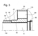
- a sliding-improving coating 80 can also be provided directly on the element foot 48 if, as can be seen from the simplified representation of FIG. 3, this is on the radial inner side of the element foot 48 of the output side Transmission element 116 is provided.
- the output side transmission element 116 sits - dispensing with a bearing 56 - directly on the transmission input shaft 9, and is just like the sliding bearing of FIG. 2 alone axially secured by the fixing elements 66, 68.
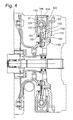
- Fig. 4 differs from Fig. 1 by the formation of the circumferential spring set 129 of the damping device 130, wherein the circumferential spring set is here only in one piece.
- drive elements 132 on the drive side 132 are provided on the primary flange 31 and sealing plate for acting on the circumferential spring set 129, which is supported on the output side drive element 144 provided on the hub disc 136 at the other end.
- the hub disc 136 is here directly on the flywheel 50 and thus rotatably received with the output-side transmission element 116.
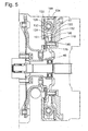
- Fig. 5 differs from the embodiment of FIG. 4 by the measure to form the element foot 48 on the hub disc 136, so that the flywheel 50 of the output-side transmission element 116 emits its centering function to the hub disc 136. Instead, the flywheel 50 is centered on a support projection 176 of the hub disc 136 and connected by the riveting 146 fixed to the hub disc 136.
Abstract
Description
Die Erfindung betrifft einen Torsionsschwingungsdämpfer gemäß dem Oberbegriff des Anspruches 1.The invention relates to a torsional vibration damper according to the preamble of
Durch die
Bei der Montage des Torsionsschwingungsdämpfers der
Der Erfindung liegt die Aufgabe zugrunde, einen Torsionsschwingungsdämpfer derart auszubilden, dass dieser auch nach Abschluss einer Montage Zugang zu einem Bereich gewährt, in welchem eine Verbindung mit dem Antrieb oder einem dem Antrieb zumindest bewegungsmäßig zugeordneten Bauteil hergestellt ist.The invention has the object of providing a torsional vibration damper in such a way that it also after completion of an assembly access to a Area granted in which a connection to the drive or a drive at least the movement associated component is made.
Diese Aufgabe wird erfindungsgemäß durch das im Kennzeichen des Anspruches 1 angegebene Merkmal gelöst.This object is achieved by the feature specified in the characterizing part of
Bei einem über einen Elementenfuß verfügenden Bauteil des abtriebsseitigen Übertragungselementes ist erfindungsgemäß vorgesehen, das abtriebsseitige Übertragungselement mit einer Ausnehmung für den Durchgang von Befestigungselementen oder für deren Montage auszubilden, wobei diese Befestigungselemente mit Vorzug durch Niete gebildet werden, welche den Primärflansch des antriebsseitigen Übertragungselementes mit einer Antriebsplatte verbinden. Die Antriebsplatte ist in vorteilhafter Ausgestaltung im Wesentlichen topfförmig mit einem erheblichen axialen Erstreckungsanteil ausgebildet, wodurch ein axialer Durchgangsraum für zumindest ein momentenübertragendes Element, wie beispielsweise eine Antriebswelle, geschaffen wird. Die Antriebsplatte ihrerseits kann mit Vorzug mittels einer lösbaren Befestigung an einer axial flexiblen Platte angebunden sein, die wiederum am Antrieb, wie der Kurbelwelle, befestigt ist.In the case of a component of the driven-side transmission element which has an element base, it is provided according to the invention to form the output-side transmission element with a recess for the passage of fastening elements or for their mounting, whereby these fastening elements are preferably formed by rivets which comprise the primary flange of the drive-side transmission element with a drive plate connect. The drive plate is formed in an advantageous embodiment substantially pot-shaped with a considerable axial extension portion, whereby an axial passage space for at least one torque-transmitting element, such as a drive shaft, is created. The drive plate, in turn, may be preferably connected by means of a releasable attachment to an axially flexible plate, which in turn is attached to the drive, such as the crankshaft.
Dieser Vorteil stellt sich unabhängig davon ein, ob das abtriebsseitige Übertragungselement nun unmittelbar über einen Elementenfuß an dem Abtrieb positioniert ist, oder aber mittels einer Lagerung, die zwischen dem Elementenfuß und dem Abtrieb angeordnet ist, wobei eine derartige Lagerung mit Vorzug als Wälzlagerung ausgebildet ist, ebenso allerdings auch in Form einer Gleitlagerung realisiert sein kann. Ebenso unabhängig hiervon ist, ob der Elementenfuß an einer abtriebsseitigen Schwungmasse oder an einem mit derselben drehfest verbundenen abtriebsseitigen Ansteuerelement für einen Umfangsfedersatz der Dämpfungseinrichtung vorgesehen ist, wobei dieses Ansteuerelement durch eine Nabenscheibe oder durch Deckbleche gebildet sein kann. Eine Nabenscheibe wird hierbei mit Vorzug an einteiligen Umfangsfedersätzen vorgesehen sein, Deckbleche dagegen in Verbindung mit mehrteiligen Umfangsfedersätzen, wobei die Mehrteiligkeit mit Vorzug durch radial gegeneinander versetzte Teile des Umfangsfedersatzes und einer Nabenscheibe zum Ausdruck kommt, die zwischen den einzelnen Umfangsfedersätzen wirksam ist, wobei die Nabenscheibe sowohl gegenüber dem antriebsseitigen Übertragungselement als auch gegenüber dem abtriebsseitigen Übertragungselement jeweils relativ verdrehbar ist.This advantage arises irrespective of whether the output-side transmission element is now positioned directly on the output via an element foot, or else by means of a bearing which is arranged between the element foot and the output, such a bearing being designed as roller bearing, but also in the form of a plain bearing can be realized. Equally independent of this is whether the element foot is provided on a driven-side flywheel or on a drive-side driving element connected to it in a rotationally fixed manner for a circumferential spring set of the damping device, this drive element being able to be formed by a hub disc or cover plates. A hub disc is hereby preferably provided on one-piece circumferential spring sets, cover plates, however, in conjunction with multi-part circumferential spring sets, the multi-part is preferably expressed by radially staggered parts of the circumferential spring set and a hub disc, which is effective between the individual circumferential spring sets, wherein the hub disc in each case relative to the drive-side transmission element as well as relative to the output-side transmission element is in each case relatively rotatable.
Von Vorteil ist die Ausbildung desjenigen Bauteiles des abtriebsseitigen Übertragungselementes, das gegenüber dem Abtrieb positioniert werden soll, mit dem Elementenfuß. Bei direkter Anordnung des abtriebsseitigen Übertragungselementes auf der Getriebeeingangswelle kann dadurch eine geeignete Kontaktfläche geschaffen werden.The advantage of the formation of that component of the output-side transmission element, which is to be positioned opposite the output, with the elements foot. In a direct arrangement of the output-side transmission element on the transmission input shaft, a suitable contact surface can be created thereby.
Der bereits erwähnte Umfangsfedersatz der Dämpfungseinrichtung ist in einer Kammer des antriebsseitigen Übertragungselementes aufgenommen, die in Achsrichtung zwischen dem Primärflansch und einem demselben zugeordneten Dichtblech ausgebildet und zumindest teilweise mit viskosem Medium befüllt ist. Um einem Verlust dieses viskosen Mediums vorzubeugen, sind Dichtungen vorgesehen, von denen jede mit jeweils einem Befestigungsende an je einem der Übertragungselemente aufgenommen und mit jeweils einem Dichtende in den Erstreckungsbereich des jeweils anderen Übertragungselementes geführt ist. Hierbei wirken mit Vorzug beide Dichtungen berührungsfrei, um die beim erfindungsgemäßen Torsionsschwingungsdämpfer vorhandene hohe Entkopplungsgüte nicht zu beeinträchtigen. Mit Vorzug wirkt hierbei eine erste Dichtung dem Austritt viskosen Mediums aus der Kammer nach radial innen entgegen, während eine zweite Dichtung den Austritt des viskosen Mediums in Richtung zum abtriebsseitigen Übertragungselement verhindert.The above-mentioned circumferential spring set of the damping device is accommodated in a chamber of the drive-side transmission element, which is formed in the axial direction between the primary flange and a same associated sealing plate and at least partially filled with viscous medium. To prevent loss of this viscous medium, seals are provided, each of which is accommodated with one attachment end on each one of the transmission elements and is guided in each case with a sealing end in the extension region of the respective other transmission element. In this case, both seals act without contact in order to avoid adversely affecting the high decoupling quality present in the torsional vibration damper according to the invention. With preference, in this case, a first seal counteracts the exit of viscous medium from the chamber radially inward, while a second seal prevents the exit of the viscous medium in the direction of the output-side transmission element.
Obwohl das antriebsseitige Übertragungselement aufgrund seiner Befestigung an der Kurbelwelle gegenüber dem Antrieb zentriert ist, das abtriebsseitige Übertragungselement dagegen aufgrund seiner Lagerung auf der Getriebeeingangswelle gegenüber dem Abtrieb zentriert ist, sind die beiden Übertragungselemente dennoch zu einer Bewegung im Wesentlichen um eine gemeinsame Drehachse befähigt, insbesondere wenn die Kurbelwelle mittels einer sogenannten "Pilotlagerung" das antriebsseitige Ende der Getriebeeingangswelle zentrierend aufnimmt.Although the drive-side transmission element is centered relative to the drive due to its attachment to the crankshaft, the output-side transmission element is centered relative to the output due to its bearing on the transmission input shaft, the two transmission elements are nevertheless capable of movement substantially about a common axis of rotation, especially if the crankshaft centering receives the drive-side end of the transmission input shaft by means of a so-called "pilot bearing".
Die Erfindung wird anhand eines Ausführungsbeispieles näher erläutert. Es zeigt:
- Figur 1:
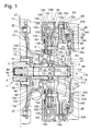
- Einen Längsschnitt durch einen mit Reibungskupplung versehenen Torsionsschwingungsdämpfer mit zweiteiligem Umfangsfedersatz und Anordnung einer Schwungmasse eines abtriebsseitigen Übertragungselementes über einer als Wälzlagerung ausgebildete Lagerung auf einer Getriebeeingangswelle;
- Figur 2:
- eine vergrößerte Herauszeichnung des in Fig. 1 eingekreisten Bereiches, allerdings mit Ausbildung der Lagerung als Gleitlagerung;
- Figur 3:
- wie Fig. 2, aber mit direkter Anordnung der Schwungmasse auf der Getriebeeingangswelle;
- Figur 4:
- wie Fig. 1, aber mit einteiliger Ausbildung des Umfangsfedersatzes;
- Figur 5:
- wie Fig. 4, aber mit Anordnung des abtriebsseitigen Übertragungselementes über eine Nabenscheibe auf der Lagerung.
- FIG. 1:
- A longitudinal section through a provided with friction clutch torsional vibration damper with two-piece circumferential spring and arrangement of a flywheel of a driven side Transmission element on a bearing designed as a roller bearing on a transmission input shaft;
- FIG. 2:
- an enlarged drawing of the circled in Figure 1 area, but with formation of storage as a sliding bearing.
- FIG. 3:
- like Figure 2, but with direct arrangement of the flywheel on the transmission input shaft.
- FIG. 4:
- as shown in Figure 1, but with one-piece design of the circumferential spring set.
- FIG. 5:
- as shown in FIG. 4, but with the arrangement of the driven-side transmission element via a hub disc on the storage.
In Fig. 1 ist als Antrieb 1 eine Kurbelwelle 3 einer Brennkraftmaschine dargestellt, die in einer mittigen Aufnahme 5 über eine Pilotlagerung 7 zur Zentrierung einer Getriebeeingangswelle 9 verfügt, die, bezogen auf das dargestellte System, als Abtrieb 11 wirksam ist. Die Kurbelwelle 3 weist einen Kurbelwellenflansch 13 auf, an welchem über lösbare Befestigungsmittel 19 eine axial elastische Platte 15 befestigt ist, die sich nach radial außen erstreckt und dort eine Verbindung eingeht mit einer Antriebsplatte 25. Zur Herstellung dieser Verbindung sind an der axial elastischen Platte 15 Gewindehülsen 17 befestigt, in welche lösbare Befestigungsmittel 20 nach Durchdringung von Öffnungen in der Antriebsplatte 25 einführbar sind. Die Antriebsplatte 25 ihrerseits trägt einen Zahnkranz 27, der zum Eingriff mit einem nicht dargestellten Starterritzel vorgesehen ist.In Fig. 1 as a
Die Antriebsplatte 25 verläuft insbesondere im radial inneren Bereich mit einer deutlichen Axialkomponente, wodurch ein axialer Durchgangsraum 28 für zumindest ein momentenübertragendes Element 160, wie beispielsweise eine Antriebswelle, geschaffen wird. Im radial innersten Bereich geht die Antriebsplatte 25 wieder in einen Bereich mit im Wesentlichen radialer Erstreckung über, welcher mittels Befestigungselementen 29 zur festen Verbindung der Antriebsplatte 25 mit einem Primärflansch 31 eines antriebsseitigen Übertragungselementes 35 vorgesehen ist. Die Befestigungselemente 29 sind vorzugsweise als Niete oder Schrauben ausgebildet, denkbar sind aber auch eine Verschleißung oder eine Verstemmung als Befestigungselement 29. Sowohl das radial innere Ende der Antriebsplatte 25 als auch das radial innere Ende des Primärflansches 31 vermögen sich jeweils auf einem im Wesentlichen axial verlaufenden Schenkel 44 eines Führungshohlzapfens 40 abzustützen, der, im Wesentlichen senkrecht zum Axialschenkel 44, über einen im Wesentlichen radial verlaufenden Schenkel 42 zur Befestigung am Kurbelwellenflansch 13 mittels der bereits erwähnten lösbaren Befestigungsmittel 19 dient. Wie aus Fig. 1 sehr gut ersichtlich ist, dient der Führungshohlzapfen 40 für eine Zentrierung von Antriebsplatte 25 und Primärflansch 31 gegenüber einer Drehachse 112, die für Kurbelwelle 3 und Getriebeeingangswelle 9 im Wesentlichen gleich ist.The
Das bereits erwähnte radial innere Ende des Primärflansches 31 ist mit einer Umkantung 37 versehen, die sich im Wesentlichen in Richtung zum Abtrieb 11 erstreckt und mit ihrem axial freien Ende mittels eines in Achsrichtung vorgesehenen ersten Spaltes 81 von einer auf der Getriebeeingangswelle 9 angeordneten Lagerung 56 getrennt ist, während das freie Ende der Umkantung 37 mittels eines radialen zweiten Spaltes 82 von einem Axialvorsprung 52 an einem Elementenfuß 48 getrennt ist, wobei dieser Elementenfuß 48 an seiner der Lagerung 56 zugewandten radialen Innenseite mit einer Radialprofilierung 54 versehen ist, um die Lagerung 56 in Achsrichtung fest aufnehmen zu können. Die Lagerung 56 ist an ihrer radialen Innenseite durch Aufpressen auf die Getriebeeingangswelle 9 gegenüber derselben bewegungsgesichert aufgenommen.The already mentioned radially inner end of the
Näher auf die Lagerung 56 eingehend, ist diese gemäß Fig. 1 als Wälzlagerung 57 ausgebildet, mit einem radial äußeren Lagerring 58, der mit seiner radialen Außenseite in der Radialprofilierung 54 des Elementenfußes 48 axial festgehalten ist, während der Lagerring 58 an seiner radialen Innenseite über Wälzelemente 61 mit einem radial inneren Lagerring 60 wirkverbunden ist, der auf die Getriebeeingangswelle 9 gepresst ist.Closer to the
Obwohl somit der Elementenfuß 48, der Teil einer Schwungmasse 50 eines abtriebsseitigen Übertragungselementes 116 ist, über die Lagerung 56 axial bewegungsgesichert auf der Getriebeeingangswelle 9 angeordnet ist, ist die Getriebeeingangswelle 9 mit Vorzug durch eine Hülse 64 umschlossen, die mit einem der Lagerung 56 zugewandten abtriebsseitigem Ende 72 den radial inneren Lagerring 60 gegen eine Bewegung zum Antrieb 1 hin sichern soll, und somit diesen Lagerring 60 axial zwischen sich und einer Schulter 70 der Getriebeeingangswelle 9 hält, wobei diese Schulter 70 aufgrund eines Querschnittsüberganges an der Getriebeeingangswelle 9 entsteht. Die bereits erwähnte Hülse 64 stützt sich mit ihrem von der Lagerung 56 abgewandten, mithin also antriebsseitigen Ende 73 an einem Radialvorsprung 74 der Getriebeeingangswelle 9 ab, wobei dieser Radialvorsprung 74 durch einen in eine Vertiefung 76 der Getriebeeingangswelle 9 eingelassenen radialen Spannring 78 gebildet wird. Durch ein Zusammenwirken dieser Hülse 64 mit der Getriebeeingangswelle 9 dient die erwähnte Schulter 70 als erstes Fixierelement 66 für die Lagerung 56, das der Lagerung 56 zugewandte abtriebsseitige Ende 72 der Hülse 64 dagegen als zweites Fixierelement 68. Beide Fixierelemente 66, 68 unterstützen die axiale Festlegung der Lagerung 56 gegenüber der Getriebeeingangswelle 9, die durch das erwähnte Aufpressen bereits vorliegt.Thus, although the
Der Elementenfuß 48, der in der Umkantung 37 des Primärflansches 31 eine Hilfszentrierung 46 vorfindet, dient gemäß Fig. 1 als radiale Innenbegrenzung der Schwungmasse 50, die unmittelbar radial außerhalb des Elementenfußes 48 Ausnehmungen 84 aufweist, die im Wesentlichen mit den Befestigungselementen 29 fluchten und zum Durchgang und/oder zur Montage dieser Befestigungselemente 29 dienen. Wiederum radial außerhalb dieser Ausnehmungen 84 schließt sich eine Vernietung 146 an, durch welche Deckbleche 142, 143 drehfest an der Schwungmasse 50 aufgenommen sind. Die Deckbleche 142, 143 dienen hierbei als abtriebsseitiges Ansteuerelement 144 einer Dämpfungseinrichtung 130, die entsprechend Fig. 1 über einen zweiteiligen Umfangsfedersatz 129 verfügt. Ein erster Teil 126 des Umfangfedersatzes 129 ist im radial äußeren Bereich einer Kammer 124 angeordnet, die axial zwischen dem Primärflansch 31 und einem Dichtblech 122 vorgesehen ist, wobei das letztgenannte Dichtblech 122 an einem Axialansatz 120 des Primärflansches 31 befestigt ist, vorzugsweise mittels einer Schweißnaht. Der Axialansatz 120 erstreckt sich hierbei im Wesentlichen in Achsrichtung am Außenumfang des Radialflansches 31.The
Dieser Axialansatz 120 dient mit seiner radialen Innenseite als Führungsfläche für Gleitschuhe 134, die ihrerseits zur Aufnahme des ersten Teiles 126 des Umfangfedersatzes 129 dienen. Ferner sind an Primärflansch 31 und Dichtblech 122 jeweils antriebsseitige Ansteuerelemente 132 vorgesehen, welche den ersten Teil 126 des Umfangsfedersatzes 129ansteuern, der sich daraufhin mit seinen entgegengesetzten Federsatzenden an ersten Ansteuermitteln 138 einer Nabenscheibe 136 abstützen. Diese Nabenscheibe 136 verfügt über zweite Ansteuermittel 140, durch welche zweite Teile 128 des Umfangsfedersatzes 129 beaufschlabar sind, wobei sich diese zweiten Teile 128 mit ihren entgegengesetzten Federsatzenden an den bereits erwähnten Deckblechen 142, 143 und damit am abtriebsseitigen Ansteuerelement 144 abstützen.This
Das antriebsseitige Deckblech 143 steht mittels eines Formschlusses 148 in drehfester Verbindung mit einer Antriebsscheibe 149, die über eine Innenverzahnung 151 verfügt und über diese Innenverzahnung in Wirkverbindung mit zumindest einem Planetenrad 156 steht, das jeweils auf einer Lagerausdrückung 154 des Primärflansches 31 gelagert ist. Dem Primärflansch 31 kommt somit die Funktion eines Planetenträgers 158 eines Planetengetriebes 152 zu, während die Antriebsscheibe 149 als Hohlrad 150 wirkt.The drive-
Die Kammer 124 ist zumindest teilweise mit viskosem Medium gefüllt, weshalb nach radial innen eine erste Dichtung 162 und in Achsrichtung eine zweite Dichtung 164 vorgesehen ist. Die erste Dichtung 162 wird mit einem Befestigungsende 166 durch die Befestigungselemente 29 am Primärflansch 31 und damit am antriebsseitigen Übertragungselement 35 gesichert und greift mit einem Dichtungsende 170, das mit einem zum Primärflansch 31 vorspringenden Axialansatz 174 der Schwungmasse 50 überlappt, in den Erstreckungsbereich des abtriebsseitigen Übertragungselementes 116 ein. Die zweite Dichtung 164 ist durch die Vernietung 146 mit einem Befestigungsende 168 an der Schwungmasse 50 und damit am abtriebsseitigen Übertragungselement 116 befestigt und greift radial nach außen, wo die Dichtung 164 mit ihrem Dichtungsende 172 radial mit der Innenseite des Dichtbleches 122 überlappt, und demnach in den Erstreckungsbereich des antriebsseitigen Übertragungselementes 35 eingreift. Mit Vorzug sind beide Dichtungen 162, 164 an ihren jeweiligen Dichtungsenden 166, 168 gegenüber dem zugeordneten Bereichen des jeweiligen Übertragungselementes 35, 116 berührungsfrei, so dass keine Reibung und damit eine Reduzierung der Entkopplungsgüte der Dämpfungseinrichtung 130 befürchtet werden muss.The
Zurückkommend auf die Schwungmasse 50, nimmt diese im Bereich ihres radialen Außenumfanges durch Befestigungsmittel 86 ein Gehäuse 92 einer Reibungskupplung 88 auf, deren Druckplatte 90 über eine durch Lagerzapfen 94 im Gehäuse 92 gehaltene Membranfeder 96 verfügt, durch welche eine Anpressplatte 98 axial beaufschlagbar ist. Axial zwischen dieser Anpressplatte 98 und einer an der Schwungmasse 50 zur Abtriebsseite hin vorgesehenen Anlagefläche 100 sind Reibbeläge 104 einer Kupplungsscheibe 102 vorgesehen, wobei die Reibbeläge 104 an einer Belagfederung 106 der Kupplungsscheibe 102 beidseits aufgenommen sind. Im radial inneren Bereich weist die Kupplungsscheibe 102 eine Kupplungsnabe 108 auf, die über eine Verzahnung 110 drehfest, aber axial verlagerbar, auf einem Verzahnungsabschnitt 112 der Getriebeeingangswelle 9 angeordnet ist. Die Membranfeder 96 der Reibungskupplung 88 wirkt mit einem strichliniert angedeuteten Ausrücker 114 zusammen, der in seiner eingezeichneten Stellung A Membranfederzungen 97 die strichliniert eingezeichnete erste Position P1 gewährt, in welcher die Reibbeläge 104 der Kupplungsscheibe 102 kraftschlüssig zwischen der Anlagefläche 100 der Schwungmasse 50 und der Anpressplatte 98 eingespannt ist, und zur Übertragung eines an der Schwungmasse 50 anliegenden Drehmomentes über die Kupplungsscheibe 102 auf die Getriebeeingangswelle 9 befähigt ist. Um von diesem eingerückten Zustand in den ausgerückten Zustand zu gelangen, wird der Ausrücker 114 nach links in seine eingezeichnete Stellung B verlagert und beaufschlagt dadurch die Membranfederzungen 97 in die ebenfalls strichliniert eingezeichnete zweite Position P2, in welcher die Reibbeläge 104 zwischen Anlagefläche 100 und Anpressplatte 98 entlastet sind, so dass die Übertragung eines Momentes zwischen Schwungmasse 50 und Getriebeeingangswelle 9 zumindest reduziert ist, die Reibungskupplung 88 sich demnach zumindest in teilausgerücktem Zustand befindet.Coming back to the
Bevor der erfindungsgemäße Torsionsschwingungsdämpfer in einem Kraftfahrzeug montiert ist, soll bereits während der Verpackungs- und Transportphase eine unerwünscht starke axiale und/oder radiale Verlagerung der beiden Übertragungselemente 35, 116 zueinander vermieden werden, um Schäden am Umfangsfedersatz 129 sowie an den Dichtungen 162, 164 wirksam verhindern zu können. Aus diesem Grund greift das abtriebsseitige Übertragungselement 116 mit seinem Elementenfuß 48 an der als Hilfszentrierung 46 wirksamen Umkantung 37 des Primärflansches 31 und damit des antriebsseitigen Übertragungselementes 35 an, so dass lediglich in der Größenordnung der bereits erwähnten Spalte 81, 82 zwischen dem Axialvorsprung 52 des Elementenfußes 48 und der Hilfszentrierung 46 eine Radial- sowie eine aufeinander zugerichtete Axialverlagerung der beiden Übertragungselemente 35, 116 möglich ist.Before the torsional vibration damper according to the invention is mounted in a motor vehicle, should already during the packaging and transport phase a undesired strong axial and / or radial displacement of the two
Bevor eine Montage des Torsionsschwingungsdämpfers im Kraftfahrzeug erfolgt, besteht auf jeden Fall bereits mittels der Befestigungselemente 29 eine feste Anbindung der Antriebsplatte 25 am Primärflansch 31. Die Reibungskupplung 88 kann, muss aber zu diesem Zeitpunkt noch nicht an der Schwungmasse 50 des abtriebsseitigen Übertragungselementes 50 befestigt sein.Before an assembly of the torsional vibration damper takes place in the motor vehicle, in any case already by means of the fastening elements 29 a fixed connection of the
Für die Montage wird die Lagerung 56 gemeinsam mit dem abtriebsseitigem Übertragungselement 116 auf der Getriebeeingangswelle 9 aufgepresst und zwar vorzugsweise in einer Position, in welcher die Lagerung 56 an der Schulter 70 der Getriebeeingangswelle 9 axial zur Anlage kommt. Dadurch ist bereits das erste Fixierelement 66 wirksam. Anschließend wird die Hülse 64 über die Getriebeeingangswelle 9 geschoben und durch Einbringen des radialen Spannringes 78 in die Vertiefung 76 der Getriebeeingangswelle 9 positioniert. Damit liegt auch das zweite Fixierelement 68 für die Lagerung 56 vor. Anschließend wird das die Getriebeeingangswelle 9 beinhaltende Getriebe in Richtung zum Antrieb 1, also zur Brennkraftmaschine hin, verlagert und dabei die Getriebeeingangswelle 9 immer weiter in die Aufnahme 5 der Kurbelwelle 3 eingeschoben. Bei dieser Bewegung gleitet die Antriebsplatte 25 sowie der Primärflansch 31 mit dem jeweiligen radial inneren Ende auf die axialen Schenkel 44 des Führungshohlzapfens 40, so dass von diesem Zeitpunkt an auch das antriebsseitige Übertragungselement 35 eine Zentrierung findet. Sobald die Getriebeeingangswelle 9 mit ihrem antriebsseitigem Ende in der Pilotlagerung 7 aufgenommen ist, liegt darüber hinaus auch eine Zentrierung der Getriebeeingangswelle 9 in der Kurbelwelle 3 vor, so dass beide Wellen 3, 9 im Wesentlichen über die gleiche Drehachse 118 verfügen. Wenn bei dieser Annäherungsbewegung der beiden Wellen 3, 9 aneinander die Antriebsplatte 25 axial in Anlage an der axial elastischen Platte 15 gekommen ist, kann über die Befestigungsmittel 20 eine endgültige Verbindung hergestellt werden, wobei diese aufgrund der Zentrierung des antriebsseitigen Übertragungselementes 35 auf dem Führungshohlzapfen 40 problemlos vonstatten geht. Von diesem Zeitpunkt an verliert die vor der Montage benötigte Hilfszentrierung 37 ihre Funktion, da nun das antriebsseitige Übertragungselement 35 über die Antriebsplatte 25 an der Kurbelwelle 3 und damit am Antrieb 1 zentriert ist, während das abtriebsseitige Übertragungselement 116 weiterhin über die Lagerung 56 an der Getriebeeingangswelle 9 und damit am Abtrieb 11 zentriert ist. Wegen dieser besonderen Zentrierung der beiden Übertragungselemente 35, 116 zueinander sind jederzeit durch geringfügige axiale Verschiebebewegungen der Getriebeeingangswelle 9 gegenüber der Kurbelwelle 3 axiale Korrekturverlagerungen zwischen den beiden Übertragungselementen 35, 116 möglich, so dass für den Fall, dass zwischen Antriebsplatte 25 und Primärflansch 31, sowie zwischen abtriebsseitigem Ansteuerelement 144 und Schwungmasse 50 Toleranzen vorhanden sind, die sich in ungünstiger Weise addieren, ein Ausgleich vorgenommen werden kann. Dadurch sind die beiden Übertragungselemente 35, 116 in Achsrichtung jeweils derart zueinander einstellbar, dass jeweils optimale Toleranzen zwischen diesen Übertragungselementen 35, 116, insbesondere hierbei aber innerhalb der Dämpfungseinrichtung 130 bestehen, so dass eine optimale Entkopplungsgüte durch die Dämpfungseinrichtung 130 erzielt werden kann, die nicht durch Verspannungen oder ungewollte Reibungen innerhalb der Dämpfungseinrichtung 130 beeinträchtigt sind. Insbesondere bei Bewegungen der Kurbelwelle 3 mit einer Axialkomponente, üblicherweise als Taumelbewegungen bezeichnet, kann die axial elastische Platte 15 bereits einen Teil dieser Taumelbewegungen vor Weitergabe an das antriebsseitige Übertragungselement 35 ausfiltern, während das vorgenannte Übertragungselement 35 den Restanteil dieser Taumelbewegungen praktisch nicht auf das abtriebsseitige Übertragungselement 116 übertragen kann.For mounting, the
Ebenso vorteilhaft gestaltet sich ein Übergang zwischen dem ein- und dem ausgerückten Zustand, bei welchem Axialkräfte der Membranfeder 96 über die Anpressplatte 98 und die Kupplungsscheibe 102 auf die Schwungmasse 50 des abtriebsseitigen Übertragungselementes 116 übertragen werden. Da sich dieses Übertragungselement 116 allerdings axial an der Lagerung 56 abzustützen vermag, die ihrerseits auf der Getriebeeingangswelle 9 und damit abtriebsseitig ortsfest ist, wird dieser Kraftfluss niemals die Abtriebsseite des Torsionsschwingungsdämpfers verlassen können. Auch der Ein- oder Ausrückvorgang wird demnach keine Veränderung der Situation in der Dämpfungseinrichtung 130 auslösen.Equally advantageous is a transition between the on and the disengaged state, in which axial forces of the
Fig. 2 entspricht der eingekreisten Darstellung in Fig. 1, allerdings ist die Lagerung 56 nun durch eine Gleitlagerung 62 gebildet. Ebenso wie bei Verwendung einer Wälzlagerung wird die Gleitlagerung 62 axial fest am Elementenfuß 48 der Schwungmasse 50 des abtriebsseitigen Übertragungselementes 116 aufgenommen sein, während allerdings die radiale Innenseite der Gleitlagerung 62 zur Gewährleistung einer Relativdrehbewegung des abtriebsseitigen Übertragungselementes 116 gegenüber der Getriebeeingangswelle 9 gleitend auf der Getriebeeingangswelle 9 angeordnet sein muss. Die axiale Bewegungssicherung der Gleitlagerung 62 auf der Getriebeeingangswelle 9 erfolgt demnach allein über die Fixierelemente 66, 68, also durch die Schulter 70 an der Getriebeeingangswelle 9 sowie durch das abtriebsseitige Ende 72 der Hülse 64. Sehr gut ersichtlich in Fig. 2 ist außerdem die Wirkung der Hilfszentrierung 64 gegenüber dem Axialvorsprung 52 am Elementenfuß 48.Fig. 2 corresponds to the circled representation in Fig. 1, however, the
Zugunsten einer verbesserter Drehbarkeit der Gleitlagerung 62 auf der Getriebeeingangswelle 9 kann die Gleitlagerung 62 an ihrer radialen Innenseite mit einer gleitverbessernden Beschichtung 63 versehen sein.In favor of an improved rotatability of the sliding
Eine gleitverbessernde Beschichtung 80 kann auch unmittelbar am Elementenfuß 48 vorgesehen sein, wenn dieser, wie aus der vereinfacht dargestellten Fig. 3 ersichtlich, an der radialen Innenseite des Elementenfußes 48 des abtriebsseitigen Übertragungselementes 116 vorgesehen ist. Bei dieser Ausführung sitzt das abtriebsseitige Übertragungselement 116 - unter Verzicht auf eine Lagerung 56 - unmittelbar auf der Getriebeeingangswelle 9, und wird ebenso wie die Gleitlagerung nach Fig. 2 allein durch die Fixierelemente 66, 68 axial bewegungsgesichert.A sliding-improving
Fig. 4 unterscheidet sich von Fig. 1 durch die Ausbildung des Umfangsfedersatzes 129 der Dämpfungseinrichtung 130, wobei der Umfangsfedersatz hier lediglich einteilig ist. Ebenso wie bei Fig. 1 sind allerdings an Primärflansch 31 und Dichtblech 122 antriebsseitige Ansteuerelemente 132 zur Beaufschlagung des Umfangsfedersatzes 129 vorgesehen, der sich anderenends am abtriebsseitigen Ansteuerelement 144, vorgesehen an der Nabenscheibe 136, abstützt. Abweichend von der Ausführung nach Fig. 1 ist die Nabenscheibe 136 hier unmittelbar an der Schwungmasse 50 und damit drehfest mit dem abtriebsseitigen Übertragungselement 116 aufgenommen.Fig. 4 differs from Fig. 1 by the formation of the circumferential spring set 129 of the damping
Fig. 5 unterscheidet sich von der Ausbildung nach Fig. 4 durch die Maßnahme, den Elementenfuß 48 an der Nabenscheibe 136 anzuformen, so dass die Schwungmasse 50 des abtriebsseitigen Übertragungselementes 116 ihre Zentrierfunktion an die Nabenscheibe 136 abgibt. Stattdessen ist die Schwungmasse 50 an einem Stützvorsprung 176 der Nabenscheibe 136 zentriert und durch die Vernietung 146 fest mit der Nabenscheibe 136 verbunden.Fig. 5 differs from the embodiment of FIG. 4 by the measure to form the
- 11
- Antriebdrive
- 33
- Kurbelwellecrankshaft
- 55
- Aufnahmeadmission
- 77
- Pilotlagerungpilot bearing
- 99
- GetriebeeingangswelleTransmission input shaft
- 1111
- Abtrieboutput
- 1313
- Kurbelwellenflanschcrankshaft
- 1515
- axial elastische Platteaxially elastic plate
- 1717
- Gewindehülsethreaded sleeve
- 19, 2019, 20
- lösbare Befestigungsmittelreleasable fasteners
- 2525
- Antriebsplattedrive plate
- 2727
- Zahnkranzsprocket
- 2828
- axialer Durchgangsraumaxial passage space
- 2929
- Befestigungselementefasteners
- 3131
- Primärflanschprimary flange
- 3535
- antriebsseitiges Übertragungselementdrive-side transmission element
- 3737
- Umkantungfold back
- 4040
- FührungshohlzapfenGuiding hollow pin
- 42,4442.44
- Schenkel des FührungshohlzapfensLegs of the guide hollow pin
- 4646
- HilfszentrierungHilfszentrierung
- 4848
- Elementenfußelement base
- 5050
- SchwungmasseInertia
- 5252
- Axialvorsprung am ElementenfußAxial projection on the element foot
- 5454
- Radialprofilierungradial profiling
- 5656
- Lagerungstorage
- 5757
- Wälzlagerungroller bearing
- 58,6058.60
- Lagerringbearing ring
- 6161
- Wälzelementerolling
- 6262
- Gleitlagerungplain bearing
- 6363
- Beschichtungcoating
- 6464
- Hülseshell
- 66, 6866, 68
- Fixierelementefixing
- 7070
- Schultershoulder
- 72, 7372, 73
- EndeThe End
- 7474
- Radialvorsprungradial projection
- 7676
- Vertiefungdeepening
- 7878
- radialer Spannringradial clamping ring
- 8080
- Beschichtungcoating
- 81, 8281, 82
- Spaltgap
- 8484
- Ausnehmungenrecesses
- 8686
- Befestigungsmittelfastener
- 8888
- Reibungskupplungfriction clutch
- 9090
- Druckplatteprinting plate
- 9292
- Gehäusecasing
- 9494
- Lagerzapfenpivot
- 9696
- Membranfederdiaphragm spring
- 9797
- MembranfederzungenDiaphragm spring fingers
- 9898
- Anpressplattepressure plate
- 100100
- Anlagefläche der SchwungmasseContact surface of the flywheel
- 102102
- Kupplungsscheibeclutch disc
- 104104
- Reibbelägefriction linings
- 106106
- Belagfederunglining suspension
- 108108
- Kupplungsnabeclutch
- 110110
- Verzahnunggearing
- 112112
- Verzahnungsabschnitttoothed section
- 114114
- Ausrückerreleaser
- 116116
- abtriebsseitiges Übertragungselementoutput-side transmission element
- 118118
- Drehachseaxis of rotation
- 120120
- Axialansatz am PrimärflanschAxial shoulder on the primary flange
- 122122
- Dichtblechsealing plate
- 124124
- Kammerchamber
- 126, 128126, 128
- Teile des UmfangsfedersatzesParts of the circumferential spring set
- 129129
- UmfangsfedersatzCircumferential spring set
- 130130
- Dämpfungseinrichtungattenuator
- 132132
- antriebsseitige Ansteuerelementedrive-side control elements
- 134134
- Gleitschuheskids
- 136136
- Nabenscheibehub disc
- 138138
- erste Ansteuermittelfirst drive means
- 140140
- zweite Ansteuermittelsecond drive means
- 142, 143142, 143
- Deckblechecover plates
- 144144
- abtriebsseitiges Ansteuerelementoutput-side drive element
- 146146
- Vernietung .Riveting.
- 148148
- Formschlussform-fit
- 149149
- Antriebsscheibesheave
- 150150
- Hohlradring gear
- 151151
- Innenverzahnunginternal gearing
- 152152
- Planetengetriebeplanetary gear
- 154154
- LagerausdrückungLagerausdrückung
- 156156
- Planetenradplanet
- 158158
- Planetenträgerplanet carrier
- 160160
- momentenübertragendes Elementmoment transmitting element
- 162, 164162, 164
- Dichtungpoetry
- 166, 168166, 168
- Befestigungsendeattachment end
- 170,172170.172
- Dichtungsendesealing end
- 174174
- Axialansatzaxial shoulder
- 176176
- Stützvorsprungsupporting projection
Claims (17)
dadurch gekennzeichnet,
dass den Elementenfuß (48) aufweisende Bauteil (50; 136) radial außerhalb des Elementenfußes (48) Ausnehmungen (84) für den Durchgang und/oder zur Montage von Befestigungselementen (29) aufweist, die eine Antriebsplatte (25) für das antriebsseitige Übertragungselement (35) mit dem Primärflansch (31) desselben verbinden.Torsionsschwingungsdämpfer with a rotationally fixed to a drive (1) engaging, provided with a primary flange (31) drive-side transmission element (35) and a damping device (130) relative to the drive-side transmission element (35) drehhauslenkbaren output side transmission element (116) via at least one an output-side drive element (144) for a damping spring (130) associated circumferential spring set (129) exhibiting component (136) and a flywheel (50), of which either the component (136) or the flywheel (50) an element foot (48 ) for centered receiving on an output (11) by means of a bearing (56),
characterized,
in that the component (50; 136) having elements foot (48) has, radially outside the element foot (48), recesses (84) for the passage and / or assembly of fastening elements (29) comprising a drive plate (25) for the drive-side transmission element (25). 35) to the primary flange (31) thereof.
dadurch gekennzeichnet,
dass das antriebsseitige Übertragungselement (35) zur Aufnahme des Umfangsfedersatzes (129) über eine mit viskosem Medium befüllte Kammer (124) verfügt, die sich axial zwischen dem Primärflansch (31) und einem demselben zugeordneten Dichtblech (122) erstreckt.Torsional vibration damper according to claim 1,
characterized,
in that the drive-side transmission element (35) for receiving the circumferential spring set (129) has a chamber (124) filled with viscous medium, which extends axially between the primary flange (31) and a sealing plate (122) assigned to it.
dadurch gekennzeichnet,
dass der mit viskosem Medium befüllten Kammer (124) des antriebsseitigen Übertragungselementes (35) eine gegenüber den Ausnehmungen (84) des den Elementenfuß (48) aufweisenden Bauteils (50; 136) wirksame Dichtung (162) zugeordnet ist.Torsional vibration damper according to claim 2,
characterized,
in that the chamber (124) of the drive-side transmission element (35) filled with viscous medium is associated with a seal (162) which is effective with respect to the recesses (84) of the component foot (48;
dadurch gekennzeichnet,
dass die Schwungmasse (50) des abtriebsseitigen Übertragungselementes (116) gegenüber der Nabenscheibe (136) weiter nach radial innen geführt ist, und dort den Elementenfuß (48) zur Positionierung gegenüber der Lagerung (56) aufweist.Torsionsschwingungsdämpfer according to claim 1, 2 or 3 with a drive element (144) for one of the damping device (130) associated circumferential spring set (129) having component (136) in the form of a hub disc,
characterized,
that the flywheel (50) of the output side transmission element (116) relative to the hub disc (136) is guided further radially inward, and there has the elements foot (48) for positioning relative to the bearing (56).
dadurch gekennzeichnet,
dass die Nabenscheibe (136) gegenüber der Schwungmasse (50) radial weiter nach innen geführt ist, und dort den Elementenfuß (48) zur Positionierung gegenüber der Lagerung (56) aufweist.Torsional vibration damper according to claim 1, 2 or 3,
characterized,
that the hub plate is guided (136) against the flywheel (50) radially further inside, and there has the element base (48) for positioning with respect to the bearing (56).
dadurch gekennzeichnet,
dass die den Primärflansch (31) des antriebsseitigen Übertragungselementes (35) mit dem Antrieb (1) verbindende Antriebsplatte (25) eine axiale Distanz zwischen dem Primärflansch (31) des antriebsseitigen Übertragungselementes (35) und einer am Antrieb (1) befestigten, axial elastischen Platte (15) überbrückt.Torsional vibration damper according to one of claims 1 to 5,
characterized,
in that the drive plate (25) connecting the primary flange (31) of the drive-side transmission element (35) to the drive (1) has an axial distance between the primary flange (31) of the drive-side transmission element (35) and an axially elastic one Bridge plate (15).
dadurch gekennzeichnet,
dass die axial elastische Platte (15) gemeinsam mit einem Führungshohlzapfen (40) am Antrieb (1) befestigt ist, wobei der Führungshohlzapfen (40) zur Zentrierung des antriebsseitigen Übertragungselementes (35) zumindest während einer Montage am Antrieb (1) vorgesehen ist.Torsional vibration damper according to claim 6,
characterized,
in that the axially elastic plate (15) is fastened together with a guide hollow pin (40) on the drive (1), wherein the guide hollow pin (40) for centering the drive-side transmission element (35) at least during mounting on the drive (1) is provided.
dadurch gekennzeichnet,
dass der Führungshohlzapfen (40) axial in den Erstreckungsbereich von Antriebsplatte (25) und Primärflansch (31) eingreift.Torsional vibration damper according to claim 6 or 7,
characterized,
in that the guide hollow pin (40) engages axially in the extension area of the drive plate (25) and the primary flange (31).
dadurch gekennzeichnet,
dass die Antriebsplatte (25) im wesentlichen topfförmig mit einem erheblichen axialen Erstreckungsanteil zur Schaffung eines axialen Durchgangsraumes (28) für zumindest ein momentenübertragendes Element (60) ausgebildet ist.Torsional vibration damper according to one of claims 6 to 8,
characterized,
in that the drive plate (25) is substantially pot-shaped with a considerable axial extension portion for creating an axial passage space (28) for at least one moment-transmitting element (60).
dadurch gekennzeichnet,
dass der mit viskosem Medium befüllten Kammer (124) zusätzlich zur ersten Dichtung (162) eine zweite Dichtung (164) axial benachbart zum abtriebsseitigen Übertragungselement (116) zugeordnet ist.Torsional vibration damper according to at least one of claims 3 to 9,
characterized,
that the filled with viscous medium chamber (124) to the first seal (162) a second seal (164) is associated with axially adjacent to the output-side transmission element (116) additionally.
dadurch gekennzeichnet,
dass die erste Dichtung (162) mit einem Befestigungsende (166) am Primärflansch (31) des antriebsseitigen Übertragungselementes (35) angreift und mit einem Dichtungsende (170) in den Erstreckungsbereich eines Axialansatzes (174) am abtriebsseitigen Übertragungselement (116) geführt ist, den das Dichtungsende (117) im wesentlichen radial umschließt.Torsional vibration damper according to one of claims 3 to 10,
characterized,
in that the first seal (162) engages with a fastening end (166) on the primary flange (31) of the drive-side transmission element (35) and with a sealing end (170) in the extension region of an axial extension (174) is guided on the output-side transmission element (116) which surrounds the seal end (117) substantially radially.
dadurch gekennzeichnet,
dass die zweite Dichtung (164) mit einem Befestigungsende (168) an der Schwungmasse (50) des abtriebsseitigen Übertragungselementes (116) befestigt ist, und mit einem Dichtungsende (172) radial in den Erstreckungsbereich des Dichtbleches (122) des antriebsseitigen Übertragungselementes (35) geführt ist.Torsional vibration damper according to claim 10,
characterized,
in that the second seal (164) is fastened with a fastening end (168) to the flywheel (50) of the driven-side transmission element (116) and with a sealing end (172) radially into the extension region of the sealing plate (122) of the drive-side transmission element (35) is guided.
dadurch gekennzeichnet,
dass wenigstens eine der beiden Dichtungen (162,164) mit ihrem Befestigungsende (166,168) derart am jeweiligen Übertragungselement (35,116) aufgenommen und in Richtung zum jeweils anderen Übertragungselement (35,116) geführt ist, dass sie mit ihrem jeweiligen Dichtungsende (170,172) im wesentlichen berührungsfrei gegenüber dem letztgenannten Übertragungselement (35,116) zur Ausrichtung gelangt.Torsional vibration damper according to one of claims 10 to 12,
characterized,
in that at least one of the two seals (162, 164) with its fastening end (166, 168) is received on the respective transmission element (35, 116) and guided in the direction of the respective other transmission element (35, 116) in such a way that with its respective sealing end (170, 172) it is substantially non-contact with respect to the latter the latter transmission element (35,116) comes to alignment.
dadurch gekennzeichnet,
dass das abtriebsseitige Ansteuerelement (144) am abtriebsseitigen Übertragungselement (116) für den Umfangsfedersatz (129) durch zumindest ein an der Schwungmasse (50) dieses Übertragungselementes (116) befestigtes Deckblech (142,143) gebildet ist, das über einen radial ersten Teil (126) des Umfangsfedersatzes (129) mit einer Nabenscheibe (136) verbunden ist, die ihrerseits über einen radial zweiten Teil (128) des Umfangsfedersatzes (129) mit antriebsseitigen Ansteuerelementen (132) des antriebsseitigen Übertragungselementes (35) in Verbindung steht, wobei die Nabenscheibe (136) sowohl gegenüber dem antriebsseitigen Übertragungselement (35) als auch gegenüber dem abtriebsseitigen Übertragungselement (116) relativ drehbar ist.Torsional vibration damper according to one of claims 1 to 13,
characterized,
that the output-side control element (144) for the peripheral spring assembly (129) an (50) of this transmission element (116) fixed to the output-side transmission element (116) through at least on the flywheel Cover plate (142,143) is formed, which is connected via a radially first part (126) of the circumferential spring set (129) with a hub disc (136) which in turn via a radially second portion (128) of the circumferential spring set (129) with drive-side drive elements (132 ) of the drive-side transmission element (35) is in communication, wherein the hub disc (136) relative to both the drive-side transmission element (35) and relative to the output-side transmission element (116) is relatively rotatable.
dadurch gekennzeichnet,
dass das abtriebsseitige Ansteuerelement (144) am abtriebsseitigen Übertragungselement (116) für den Umfangsfedersatz (129) durch eine an der Schwungmasse (50) dieses Übertragungselementes (116) befestigte Nabenscheibe (136) gebildet ist, die über den Umfangsfedersatz (129) mit antriebsseitigen Ansteuerelementen (132) des antriebsseitigen Übertragungselementes (35) in Wirkverbindung steht.Torsional vibration damper according to one of claims 1 to 14,
characterized,
in that the output-side drive element (144) on the output-side transmission element (116) for the circumferential spring set (129) is formed by a hub disc (136) fastened to the flywheel (50) of this transmission element (116), via the circumferential spring set (129) with drive-side drive elements (132) of the drive-side transmission element (35) is in operative connection.
dadurch gekennzeichnet,
dass das abtriebsseitige Übertragungselement (116) an seiner Schwungmasse (50 zur Aufnahme einer Reibungskupplung (88) dient.Torsional vibration damper according to one of claims 1 to 15,
characterized,
that the output-side transmission element (116) on its flywheel (50 for receiving a friction clutch (88) is used.
dadurch gekennzeichnet,
dass der Elementenfuß (48) an seinem der Getriebeeingangswelle (9) zugewandten Innendurchmesser mit einer reibungsvermindernden Beschichtung (80) versehen ist.Torsional vibration damper according to one of claims 1 to 16,
characterized,
that the element base (48) (9) facing inner diameter is provided with a friction-reducing coating (80) at its the transmission input shaft.
Applications Claiming Priority (2)
| Application Number | Priority Date | Filing Date | Title |
|---|---|---|---|
| DE102004045366A DE102004045366A1 (en) | 2004-09-18 | 2004-09-18 | torsional vibration damper |
| EP05019610A EP1637766B1 (en) | 2004-09-18 | 2005-09-09 | Torsional vibration damper |
Related Parent Applications (1)
| Application Number | Title | Priority Date | Filing Date |
|---|---|---|---|
| EP05019610A Division EP1637766B1 (en) | 2004-09-18 | 2005-09-09 | Torsional vibration damper |
Publications (3)
| Publication Number | Publication Date |
|---|---|
| EP1701058A2 true EP1701058A2 (en) | 2006-09-13 |
| EP1701058A3 EP1701058A3 (en) | 2006-09-20 |
| EP1701058B1 EP1701058B1 (en) | 2008-03-05 |
Family
ID=35431331
Family Applications (3)
| Application Number | Title | Priority Date | Filing Date |
|---|---|---|---|
| EP06011995A Active EP1701059B1 (en) | 2004-09-18 | 2005-09-09 | Torsional vibration damper |
| EP06011994A Active EP1701058B1 (en) | 2004-09-18 | 2005-09-09 | Torsional vibration damper |
| EP05019610A Not-in-force EP1637766B1 (en) | 2004-09-18 | 2005-09-09 | Torsional vibration damper |
Family Applications Before (1)
| Application Number | Title | Priority Date | Filing Date |
|---|---|---|---|
| EP06011995A Active EP1701059B1 (en) | 2004-09-18 | 2005-09-09 | Torsional vibration damper |
Family Applications After (1)
| Application Number | Title | Priority Date | Filing Date |
|---|---|---|---|
| EP05019610A Not-in-force EP1637766B1 (en) | 2004-09-18 | 2005-09-09 | Torsional vibration damper |
Country Status (3)
| Country | Link |
|---|---|
| EP (3) | EP1701059B1 (en) |
| AT (3) | ATE398250T1 (en) |
| DE (4) | DE102004045366A1 (en) |
Cited By (2)
| Publication number | Priority date | Publication date | Assignee | Title |
|---|---|---|---|---|
| WO2009153149A1 (en) * | 2008-06-16 | 2009-12-23 | Zf Friedrichshafen Ag | Bearing arrangement for a drive shaft of a transmission |
| WO2010091810A1 (en) * | 2009-02-11 | 2010-08-19 | Magna Powertrain Ag & Co Kg | Dual mass fly wheel |
Families Citing this family (12)
| Publication number | Priority date | Publication date | Assignee | Title |
|---|---|---|---|---|
| WO2007041980A1 (en) * | 2005-10-11 | 2007-04-19 | Luk Lamellen Und Kupplungsbau Beteiligungs Kg | Torque transmission device |
| DE102005053822B4 (en) | 2005-11-11 | 2008-08-28 | Zf Friedrichshafen Ag | Torsional vibration damper for a hydrodynamic coupling arrangement |
| DE102006057779A1 (en) * | 2006-12-07 | 2008-06-12 | Zf Friedrichshafen Ag | Flywheel, for a motor vehicle transmission, has a radial inner centering unit to hold and center the clutch disk shaft |
| DE102007023139A1 (en) * | 2007-05-16 | 2009-02-19 | Audi Ag | Drive device for motor vehicle, has combustion engine and speed gearbox, and driving torque of combustion engine reduces cascade gearbox |
| FR2916823B1 (en) | 2007-05-31 | 2012-05-04 | Valeo Embrayages | IMPROVED FLYWHEEL FOR MOTOR VEHICLE |
| DE102008011768B4 (en) * | 2008-02-28 | 2017-02-02 | Volkswagen Ag | Arrangement for an internal combustion engine |
| DE102008043663B4 (en) | 2008-11-12 | 2022-01-27 | Zf Friedrichshafen Ag | Torsional vibration damper, in particular for the drive train of a vehicle |
| DE102012219800B4 (en) * | 2011-11-11 | 2019-02-28 | Schaeffler Technologies AG & Co. KG | Torsional vibration damper and clutch unit |
| DE102012223950B4 (en) * | 2012-01-20 | 2018-10-25 | Schaeffler Technologies AG & Co. KG | Transmission unit with integrated damper system |
| DE102014221686B4 (en) * | 2014-10-24 | 2017-03-16 | Schaeffler Technologies AG & Co. KG | torsional vibration dampers |
| CN108119605B (en) * | 2017-12-22 | 2019-09-03 | 宁波宏协股份有限公司 | A kind of double mass flywheel with sliding shoe formula centrifugal pendulum |
| US10576821B2 (en) * | 2018-04-03 | 2020-03-03 | Deere & Company | Drive mechanism with replaceable seal and associated method |
Citations (8)
| Publication number | Priority date | Publication date | Assignee | Title |
|---|---|---|---|---|
| DE3411090A1 (en) * | 1983-11-10 | 1985-05-23 | LuK Lamellen und Kupplungsbau GmbH, 7580 Bühl | Damping device for taking up or compensating torsional impacts |
| DE3447926A1 (en) * | 1983-11-15 | 1985-11-14 | LuK Lamellen und Kupplungsbau GmbH, 7580 Bühl | Device for compensating for rotary shocks |
| DE4311908A1 (en) * | 1992-04-18 | 1993-10-21 | Luk Lamellen & Kupplungsbau | Torque transmission device |
| US5878856A (en) * | 1996-03-08 | 1999-03-09 | Fichtel & Sachs Ag | Flywheel device with a system of plain bearings |
| DE3448520C2 (en) * | 1983-11-10 | 1999-03-18 | Luk Lamellen & Kupplungsbau | Mechanical torque transmission device |
| DE19549459C2 (en) * | 1994-02-08 | 2000-03-30 | Exedy Corp | Power transmission device with vibration damper |
| DE10012499A1 (en) * | 1999-03-16 | 2000-09-21 | Luk Lamellen & Kupplungsbau | Connection for a vehicle clutch assembly and a torsional damper unit, comprises of a snap fit connection plate and cover assembly |
| US6418620B1 (en) * | 1997-08-04 | 2002-07-16 | Luk Lamellen Und Kupplungsbau | Method of making bearings for use in torsional vibration dampers |
Family Cites Families (1)
| Publication number | Priority date | Publication date | Assignee | Title |
|---|---|---|---|---|
| DE19861365B4 (en) * | 1998-05-07 | 2007-03-22 | Zf Sachs Ag | Torsional vibration damper with at least one bearing between damper elements |
-
2004
- 2004-09-18 DE DE102004045366A patent/DE102004045366A1/en not_active Withdrawn
-
2005
- 2005-09-09 DE DE502005000345T patent/DE502005000345D1/en active Active
- 2005-09-09 EP EP06011995A patent/EP1701059B1/en active Active
- 2005-09-09 DE DE502005004394T patent/DE502005004394D1/en active Active
- 2005-09-09 EP EP06011994A patent/EP1701058B1/en active Active
- 2005-09-09 AT AT06011995T patent/ATE398250T1/en not_active IP Right Cessation
- 2005-09-09 AT AT05019610T patent/ATE352732T1/en not_active IP Right Cessation
- 2005-09-09 EP EP05019610A patent/EP1637766B1/en not_active Not-in-force
- 2005-09-09 AT AT06011994T patent/ATE388351T1/en not_active IP Right Cessation
- 2005-09-09 DE DE502005003086T patent/DE502005003086D1/en active Active
Patent Citations (9)
| Publication number | Priority date | Publication date | Assignee | Title |
|---|---|---|---|---|
| DE3411090A1 (en) * | 1983-11-10 | 1985-05-23 | LuK Lamellen und Kupplungsbau GmbH, 7580 Bühl | Damping device for taking up or compensating torsional impacts |
| DE3448520C2 (en) * | 1983-11-10 | 1999-03-18 | Luk Lamellen & Kupplungsbau | Mechanical torque transmission device |
| DE3447926A1 (en) * | 1983-11-15 | 1985-11-14 | LuK Lamellen und Kupplungsbau GmbH, 7580 Bühl | Device for compensating for rotary shocks |
| US4729465A (en) * | 1983-11-15 | 1988-03-08 | Luk Lamellen Und Kupplungsbau Gmbh | Assembly for compensating for fluctuations of torque which is transmitted by an internal combustion engine |
| DE4311908A1 (en) * | 1992-04-18 | 1993-10-21 | Luk Lamellen & Kupplungsbau | Torque transmission device |
| DE19549459C2 (en) * | 1994-02-08 | 2000-03-30 | Exedy Corp | Power transmission device with vibration damper |
| US5878856A (en) * | 1996-03-08 | 1999-03-09 | Fichtel & Sachs Ag | Flywheel device with a system of plain bearings |
| US6418620B1 (en) * | 1997-08-04 | 2002-07-16 | Luk Lamellen Und Kupplungsbau | Method of making bearings for use in torsional vibration dampers |
| DE10012499A1 (en) * | 1999-03-16 | 2000-09-21 | Luk Lamellen & Kupplungsbau | Connection for a vehicle clutch assembly and a torsional damper unit, comprises of a snap fit connection plate and cover assembly |
Cited By (2)
| Publication number | Priority date | Publication date | Assignee | Title |
|---|---|---|---|---|
| WO2009153149A1 (en) * | 2008-06-16 | 2009-12-23 | Zf Friedrichshafen Ag | Bearing arrangement for a drive shaft of a transmission |
| WO2010091810A1 (en) * | 2009-02-11 | 2010-08-19 | Magna Powertrain Ag & Co Kg | Dual mass fly wheel |
Also Published As
| Publication number | Publication date |
|---|---|
| ATE398250T1 (en) | 2008-07-15 |
| EP1637766B1 (en) | 2007-01-24 |
| ATE388351T1 (en) | 2008-03-15 |
| DE502005000345D1 (en) | 2007-03-15 |
| EP1701059B1 (en) | 2008-06-11 |
| DE102004045366A1 (en) | 2006-04-06 |
| EP1701059A3 (en) | 2006-09-27 |
| DE502005003086D1 (en) | 2008-04-17 |
| EP1701058B1 (en) | 2008-03-05 |
| ATE352732T1 (en) | 2007-02-15 |
| EP1701059A2 (en) | 2006-09-13 |
| EP1701058A3 (en) | 2006-09-20 |
| EP1637766A1 (en) | 2006-03-22 |
| DE502005004394D1 (en) | 2008-07-24 |
Similar Documents
| Publication | Publication Date | Title |
|---|---|---|
| EP1701058B1 (en) | Torsional vibration damper | |
| DE102005037514B4 (en) | Torque transmission device | |
| DE102014209618B4 (en) | multiple clutch device | |
| EP1464873A2 (en) | Torsion vibration damper for torque converter | |
| EP1582766B1 (en) | Torsional vibration damper | |
| DE112006002790B4 (en) | Hydrodynamic torque converter device with a multi-plate clutch | |
| EP2053273A1 (en) | Torsion vibration damper for torque converter | |
| DE10065874C2 (en) | Hydrodynamic coupling device | |
| DE3934798A1 (en) | Torsional vibration damper with pre-curved coil springs | |
| DE19754650A1 (en) | Torque converter with housing containing turbine wheel | |
| EP1698804B1 (en) | Friction clutch | |
| DE19727678C2 (en) | Torsional vibration damper with a planetary gear with at least one gear element | |
| DE19629497B4 (en) | Disc arrangement with damper | |
| EP1614919B1 (en) | Clutch arrangement | |
| DE19810297A1 (en) | Automotive transmission linkage between torque converter | |
| DE10358902B4 (en) | torsional vibration damper | |
| WO2020052705A1 (en) | Clutch assembly and drive unit | |
| DE10003044A1 (en) | Torsional oscillation damper is positioned between driving and driven sides of drive system and is mounted on bearing system with axial bearing area which has one surface directed towards driven side and another towards driving side | |
| DE19861365B4 (en) | Torsional vibration damper with at least one bearing between damper elements | |
| DE102004012145A1 (en) | Bypass clutch for a housing enclosed by a hydrodynamic coupling device | |
| DE19828709B4 (en) | Hydrodynamic coupling device with a lock-up clutch | |
| DE102016206503A1 (en) | torsional vibration damper | |
| EP2089636A1 (en) | Friction clutch for the drivetrain of a vehicle | |
| DE10347782B4 (en) | Hydrodynamic torque converter | |
| DE19845695B4 (en) | Torsional vibration damper with at least one protective device against damage caused by micromotion |
Legal Events
| Date | Code | Title | Description |
|---|---|---|---|
| PUAI | Public reference made under article 153(3) epc to a published international application that has entered the european phase |
Free format text: ORIGINAL CODE: 0009012 |
|
| PUAL | Search report despatched |
Free format text: ORIGINAL CODE: 0009013 |
|
| AC | Divisional application: reference to earlier application |
Ref document number: 1637766 Country of ref document: EP Kind code of ref document: P |
|
| AK | Designated contracting states |
Kind code of ref document: A2 Designated state(s): AT BE BG CH CY CZ DE DK EE ES FI FR GB GR HU IE IS IT LI LT LU LV MC NL PL PT RO SE SI SK TR |
|
| AX | Request for extension of the european patent |
Extension state: AL BA HR MK YU |
|
| AK | Designated contracting states |
Kind code of ref document: A3 Designated state(s): AT BE BG CH CY CZ DE DK EE ES FI FR GB GR HU IE IS IT LI LT LU LV MC NL PL PT RO SE SI SK TR |
|
| AX | Request for extension of the european patent |
Extension state: AL BA HR MK YU |
|
| 17P | Request for examination filed |
Effective date: 20060902 |
|
| 17Q | First examination report despatched |
Effective date: 20061025 |
|
| AKX | Designation fees paid |
Designated state(s): AT BE BG CH CY CZ DE DK EE ES FI FR GB GR HU IE IS IT LI LT LU LV MC NL PL PT RO SE SI SK TR |
|
| GRAP | Despatch of communication of intention to grant a patent |
Free format text: ORIGINAL CODE: EPIDOSNIGR1 |
|
| RIN1 | Information on inventor provided before grant (corrected) |
Inventor name: BINDIG, SEBASTIAN Inventor name: LOUKAS, ALEXANDER Inventor name: GOEBEL, HILMAR Inventor name: MANGER, ALEXANDER Inventor name: SCHIERLING, BERNHARD |
|
| GRAS | Grant fee paid |
Free format text: ORIGINAL CODE: EPIDOSNIGR3 |
|
| GRAA | (expected) grant |
Free format text: ORIGINAL CODE: 0009210 |
|
| AC | Divisional application: reference to earlier application |
Ref document number: 1637766 Country of ref document: EP Kind code of ref document: P |
|
| AK | Designated contracting states |
Kind code of ref document: B1 Designated state(s): AT BE BG CH CY CZ DE DK EE ES FI FR GB GR HU IE IS IT LI LT LU LV MC NL PL PT RO SE SI SK TR |
|
| REG | Reference to a national code |
Ref country code: GB Ref legal event code: FG4D Free format text: NOT ENGLISH |
|
| REG | Reference to a national code |
Ref country code: CH Ref legal event code: EP |
|
| REG | Reference to a national code |
Ref country code: IE Ref legal event code: FG4D Free format text: LANGUAGE OF EP DOCUMENT: GERMAN |
|
| REF | Corresponds to: |
Ref document number: 502005003086 Country of ref document: DE Date of ref document: 20080417 Kind code of ref document: P |
|
| PG25 | Lapsed in a contracting state [announced via postgrant information from national office to epo] |
Ref country code: FI Free format text: LAPSE BECAUSE OF FAILURE TO SUBMIT A TRANSLATION OF THE DESCRIPTION OR TO PAY THE FEE WITHIN THE PRESCRIBED TIME-LIMIT Effective date: 20080305 Ref country code: ES Free format text: LAPSE BECAUSE OF FAILURE TO SUBMIT A TRANSLATION OF THE DESCRIPTION OR TO PAY THE FEE WITHIN THE PRESCRIBED TIME-LIMIT Effective date: 20080616 |
|
| NLV1 | Nl: lapsed or annulled due to failure to fulfill the requirements of art. 29p and 29m of the patents act | ||
| ET | Fr: translation filed | ||
| PG25 | Lapsed in a contracting state [announced via postgrant information from national office to epo] |
Ref country code: LV Free format text: LAPSE BECAUSE OF FAILURE TO SUBMIT A TRANSLATION OF THE DESCRIPTION OR TO PAY THE FEE WITHIN THE PRESCRIBED TIME-LIMIT Effective date: 20080305 Ref country code: PL Free format text: LAPSE BECAUSE OF FAILURE TO SUBMIT A TRANSLATION OF THE DESCRIPTION OR TO PAY THE FEE WITHIN THE PRESCRIBED TIME-LIMIT Effective date: 20080305 Ref country code: SI Free format text: LAPSE BECAUSE OF FAILURE TO SUBMIT A TRANSLATION OF THE DESCRIPTION OR TO PAY THE FEE WITHIN THE PRESCRIBED TIME-LIMIT Effective date: 20080305 |
|
| REG | Reference to a national code |
Ref country code: IE Ref legal event code: FD4D |
|
| PG25 | Lapsed in a contracting state [announced via postgrant information from national office to epo] |
Ref country code: NL Free format text: LAPSE BECAUSE OF FAILURE TO SUBMIT A TRANSLATION OF THE DESCRIPTION OR TO PAY THE FEE WITHIN THE PRESCRIBED TIME-LIMIT Effective date: 20080305 Ref country code: CZ Free format text: LAPSE BECAUSE OF FAILURE TO SUBMIT A TRANSLATION OF THE DESCRIPTION OR TO PAY THE FEE WITHIN THE PRESCRIBED TIME-LIMIT Effective date: 20080305 Ref country code: PT Free format text: LAPSE BECAUSE OF FAILURE TO SUBMIT A TRANSLATION OF THE DESCRIPTION OR TO PAY THE FEE WITHIN THE PRESCRIBED TIME-LIMIT Effective date: 20080805 Ref country code: SE Free format text: LAPSE BECAUSE OF FAILURE TO SUBMIT A TRANSLATION OF THE DESCRIPTION OR TO PAY THE FEE WITHIN THE PRESCRIBED TIME-LIMIT Effective date: 20080605 Ref country code: SK Free format text: LAPSE BECAUSE OF FAILURE TO SUBMIT A TRANSLATION OF THE DESCRIPTION OR TO PAY THE FEE WITHIN THE PRESCRIBED TIME-LIMIT Effective date: 20080305 |
|
| PG25 | Lapsed in a contracting state [announced via postgrant information from national office to epo] |
Ref country code: RO Free format text: LAPSE BECAUSE OF FAILURE TO SUBMIT A TRANSLATION OF THE DESCRIPTION OR TO PAY THE FEE WITHIN THE PRESCRIBED TIME-LIMIT Effective date: 20080305 |
|
| PG25 | Lapsed in a contracting state [announced via postgrant information from national office to epo] |
Ref country code: IS Free format text: LAPSE BECAUSE OF FAILURE TO SUBMIT A TRANSLATION OF THE DESCRIPTION OR TO PAY THE FEE WITHIN THE PRESCRIBED TIME-LIMIT Effective date: 20080705 |
|
| PLBE | No opposition filed within time limit |
Free format text: ORIGINAL CODE: 0009261 |
|
| STAA | Information on the status of an ep patent application or granted ep patent |
Free format text: STATUS: NO OPPOSITION FILED WITHIN TIME LIMIT |
|
| PG25 | Lapsed in a contracting state [announced via postgrant information from national office to epo] |
Ref country code: LT Free format text: LAPSE BECAUSE OF FAILURE TO SUBMIT A TRANSLATION OF THE DESCRIPTION OR TO PAY THE FEE WITHIN THE PRESCRIBED TIME-LIMIT Effective date: 20080305 Ref country code: DK Free format text: LAPSE BECAUSE OF FAILURE TO SUBMIT A TRANSLATION OF THE DESCRIPTION OR TO PAY THE FEE WITHIN THE PRESCRIBED TIME-LIMIT Effective date: 20080305 Ref country code: IE Free format text: LAPSE BECAUSE OF FAILURE TO SUBMIT A TRANSLATION OF THE DESCRIPTION OR TO PAY THE FEE WITHIN THE PRESCRIBED TIME-LIMIT Effective date: 20080305 |
|
| 26N | No opposition filed |
Effective date: 20081208 |
|
| BERE | Be: lapsed |
Owner name: ZF FRIEDRICHSHAFEN A.G. Effective date: 20080930 |
|
| PG25 | Lapsed in a contracting state [announced via postgrant information from national office to epo] |
Ref country code: MC Free format text: LAPSE BECAUSE OF NON-PAYMENT OF DUE FEES Effective date: 20080930 Ref country code: BG Free format text: LAPSE BECAUSE OF FAILURE TO SUBMIT A TRANSLATION OF THE DESCRIPTION OR TO PAY THE FEE WITHIN THE PRESCRIBED TIME-LIMIT Effective date: 20080605 Ref country code: EE Free format text: LAPSE BECAUSE OF FAILURE TO SUBMIT A TRANSLATION OF THE DESCRIPTION OR TO PAY THE FEE WITHIN THE PRESCRIBED TIME-LIMIT Effective date: 20080305 |
|
| PG25 | Lapsed in a contracting state [announced via postgrant information from national office to epo] |
Ref country code: BE Free format text: LAPSE BECAUSE OF NON-PAYMENT OF DUE FEES Effective date: 20080930 |
|
| PG25 | Lapsed in a contracting state [announced via postgrant information from national office to epo] |
Ref country code: IT Free format text: LAPSE BECAUSE OF FAILURE TO SUBMIT A TRANSLATION OF THE DESCRIPTION OR TO PAY THE FEE WITHIN THE PRESCRIBED TIME-LIMIT Effective date: 20080305 |
|
| PG25 | Lapsed in a contracting state [announced via postgrant information from national office to epo] |
Ref country code: CY Free format text: LAPSE BECAUSE OF FAILURE TO SUBMIT A TRANSLATION OF THE DESCRIPTION OR TO PAY THE FEE WITHIN THE PRESCRIBED TIME-LIMIT Effective date: 20080305 |
|
| PG25 | Lapsed in a contracting state [announced via postgrant information from national office to epo] |
Ref country code: AT Free format text: LAPSE BECAUSE OF NON-PAYMENT OF DUE FEES Effective date: 20080909 |
|
| REG | Reference to a national code |
Ref country code: CH Ref legal event code: PL |
|
| PG25 | Lapsed in a contracting state [announced via postgrant information from national office to epo] |
Ref country code: LU Free format text: LAPSE BECAUSE OF NON-PAYMENT OF DUE FEES Effective date: 20080909 Ref country code: HU Free format text: LAPSE BECAUSE OF FAILURE TO SUBMIT A TRANSLATION OF THE DESCRIPTION OR TO PAY THE FEE WITHIN THE PRESCRIBED TIME-LIMIT Effective date: 20080906 |
|
| PG25 | Lapsed in a contracting state [announced via postgrant information from national office to epo] |
Ref country code: TR Free format text: LAPSE BECAUSE OF FAILURE TO SUBMIT A TRANSLATION OF THE DESCRIPTION OR TO PAY THE FEE WITHIN THE PRESCRIBED TIME-LIMIT Effective date: 20080305 |
|
| PG25 | Lapsed in a contracting state [announced via postgrant information from national office to epo] |
Ref country code: CH Free format text: LAPSE BECAUSE OF NON-PAYMENT OF DUE FEES Effective date: 20090930 Ref country code: GR Free format text: LAPSE BECAUSE OF FAILURE TO SUBMIT A TRANSLATION OF THE DESCRIPTION OR TO PAY THE FEE WITHIN THE PRESCRIBED TIME-LIMIT Effective date: 20080606 Ref country code: LI Free format text: LAPSE BECAUSE OF NON-PAYMENT OF DUE FEES Effective date: 20090930 |
|
| REG | Reference to a national code |
Ref country code: FR Ref legal event code: PLFP Year of fee payment: 11 |
|
| REG | Reference to a national code |
Ref country code: FR Ref legal event code: PLFP Year of fee payment: 12 |
|
| REG | Reference to a national code |
Ref country code: FR Ref legal event code: PLFP Year of fee payment: 13 |
|
| REG | Reference to a national code |
Ref country code: FR Ref legal event code: PLFP Year of fee payment: 14 |
|
| PGFP | Annual fee paid to national office [announced via postgrant information from national office to epo] |
Ref country code: GB Payment date: 20220721 Year of fee payment: 18 Ref country code: DE Payment date: 20220609 Year of fee payment: 18 |
|
| PGFP | Annual fee paid to national office [announced via postgrant information from national office to epo] |
Ref country code: FR Payment date: 20220709 Year of fee payment: 18 |
|
| P01 | Opt-out of the competence of the unified patent court (upc) registered |
Effective date: 20230528 |