EP1705352A1 - Method and relative device for sensing the air/fuel ratio of an internal combustion engine - Google Patents
Method and relative device for sensing the air/fuel ratio of an internal combustion engine Download PDFInfo
- Publication number
- EP1705352A1 EP1705352A1 EP05425121A EP05425121A EP1705352A1 EP 1705352 A1 EP1705352 A1 EP 1705352A1 EP 05425121 A EP05425121 A EP 05425121A EP 05425121 A EP05425121 A EP 05425121A EP 1705352 A1 EP1705352 A1 EP 1705352A1
- Authority
- EP
- European Patent Office
- Prior art keywords
- signal
- engine
- air
- fuel ratio
- pressure
- Prior art date
- Legal status (The legal status is an assumption and is not a legal conclusion. Google has not performed a legal analysis and makes no representation as to the accuracy of the status listed.)
- Granted
Links
Images


Classifications
-
- F—MECHANICAL ENGINEERING; LIGHTING; HEATING; WEAPONS; BLASTING
- F02—COMBUSTION ENGINES; HOT-GAS OR COMBUSTION-PRODUCT ENGINE PLANTS
- F02D—CONTROLLING COMBUSTION ENGINES
- F02D41/00—Electrical control of supply of combustible mixture or its constituents
- F02D41/24—Electrical control of supply of combustible mixture or its constituents characterised by the use of digital means
- F02D41/2406—Electrical control of supply of combustible mixture or its constituents characterised by the use of digital means using essentially read only memories
- F02D41/2425—Particular ways of programming the data
- F02D41/2429—Methods of calibrating or learning
- F02D41/2451—Methods of calibrating or learning characterised by what is learned or calibrated
- F02D41/2454—Learning of the air-fuel ratio control
-
- F—MECHANICAL ENGINEERING; LIGHTING; HEATING; WEAPONS; BLASTING
- F02—COMBUSTION ENGINES; HOT-GAS OR COMBUSTION-PRODUCT ENGINE PLANTS
- F02D—CONTROLLING COMBUSTION ENGINES
- F02D35/00—Controlling engines, dependent on conditions exterior or interior to engines, not otherwise provided for
- F02D35/02—Controlling engines, dependent on conditions exterior or interior to engines, not otherwise provided for on interior conditions
- F02D35/023—Controlling engines, dependent on conditions exterior or interior to engines, not otherwise provided for on interior conditions by determining the cylinder pressure
-
- F—MECHANICAL ENGINEERING; LIGHTING; HEATING; WEAPONS; BLASTING
- F02—COMBUSTION ENGINES; HOT-GAS OR COMBUSTION-PRODUCT ENGINE PLANTS
- F02D—CONTROLLING COMBUSTION ENGINES
- F02D41/00—Electrical control of supply of combustible mixture or its constituents
- F02D41/02—Circuit arrangements for generating control signals
- F02D41/14—Introducing closed-loop corrections
- F02D41/1401—Introducing closed-loop corrections characterised by the control or regulation method
- F02D41/1405—Neural network control
-
- F—MECHANICAL ENGINEERING; LIGHTING; HEATING; WEAPONS; BLASTING
- F02—COMBUSTION ENGINES; HOT-GAS OR COMBUSTION-PRODUCT ENGINE PLANTS
- F02D—CONTROLLING COMBUSTION ENGINES
- F02D41/00—Electrical control of supply of combustible mixture or its constituents
- F02D41/02—Circuit arrangements for generating control signals
- F02D41/14—Introducing closed-loop corrections
- F02D41/1438—Introducing closed-loop corrections using means for determining characteristics of the combustion gases; Sensors therefor
- F02D41/1444—Introducing closed-loop corrections using means for determining characteristics of the combustion gases; Sensors therefor characterised by the characteristics of the combustion gases
- F02D41/1454—Introducing closed-loop corrections using means for determining characteristics of the combustion gases; Sensors therefor characterised by the characteristics of the combustion gases the characteristics being an oxygen content or concentration or the air-fuel ratio
- F02D41/1458—Introducing closed-loop corrections using means for determining characteristics of the combustion gases; Sensors therefor characterised by the characteristics of the combustion gases the characteristics being an oxygen content or concentration or the air-fuel ratio with determination means using an estimation
-
- G—PHYSICS
- G06—COMPUTING; CALCULATING OR COUNTING
- G06F—ELECTRIC DIGITAL DATA PROCESSING
- G06F18/00—Pattern recognition
- G06F18/20—Analysing
- G06F18/23—Clustering techniques
- G06F18/232—Non-hierarchical techniques
- G06F18/2321—Non-hierarchical techniques using statistics or function optimisation, e.g. modelling of probability density functions
- G06F18/23213—Non-hierarchical techniques using statistics or function optimisation, e.g. modelling of probability density functions with fixed number of clusters, e.g. K-means clustering
-
- F—MECHANICAL ENGINEERING; LIGHTING; HEATING; WEAPONS; BLASTING
- F02—COMBUSTION ENGINES; HOT-GAS OR COMBUSTION-PRODUCT ENGINE PLANTS
- F02D—CONTROLLING COMBUSTION ENGINES
- F02D41/00—Electrical control of supply of combustible mixture or its constituents
- F02D41/02—Circuit arrangements for generating control signals
- F02D41/14—Introducing closed-loop corrections
- F02D41/1401—Introducing closed-loop corrections characterised by the control or regulation method
- F02D2041/141—Introducing closed-loop corrections characterised by the control or regulation method using a feed-forward control element
-
- F—MECHANICAL ENGINEERING; LIGHTING; HEATING; WEAPONS; BLASTING
- F02—COMBUSTION ENGINES; HOT-GAS OR COMBUSTION-PRODUCT ENGINE PLANTS
- F02D—CONTROLLING COMBUSTION ENGINES
- F02D41/00—Electrical control of supply of combustible mixture or its constituents
- F02D41/02—Circuit arrangements for generating control signals
- F02D41/14—Introducing closed-loop corrections
- F02D41/1401—Introducing closed-loop corrections characterised by the control or regulation method
- F02D41/1404—Fuzzy logic control
-
- F—MECHANICAL ENGINEERING; LIGHTING; HEATING; WEAPONS; BLASTING
- F02—COMBUSTION ENGINES; HOT-GAS OR COMBUSTION-PRODUCT ENGINE PLANTS
- F02D—CONTROLLING COMBUSTION ENGINES
- F02D41/00—Electrical control of supply of combustible mixture or its constituents
- F02D41/02—Circuit arrangements for generating control signals
- F02D41/18—Circuit arrangements for generating control signals by measuring intake air flow
- F02D41/187—Circuit arrangements for generating control signals by measuring intake air flow using a hot wire flow sensor
Definitions
- This invention relates to control systems of the operating parameters of internal combustion engines and more particularly to a method and relative device for sensing the air/fuel ratio (briefly AFR) of an internal combustion engine, and a relative control system that uses this sensing device.
- EMS Engine Management Systems
- ECU Engine Control Units
- the EMS implements control strategies which achieve the optimum trade-off between several contradictory objectives: high output power when required by driver, low emission levels and low fuel consumptions.
- the EMS must bring and maintain the engine in a specified operating range such that the three-way catalytic converter can further reduce the harmful content of the exhaust gases.
- the EMS controls the amount of fuel injected in the engine combustion chamber (fuel pulse width), the point in the engine cycle at which the mixture air fuel is ignited (ignition timing) and in advanced engine designs, other parameters, such as the valve timings.
- the EMS determines values for these parameters from measured quantities such as speed, torque, air mass flow rate, inlet-manifold pressure, temperatures at several critical points and throttle angle.
- FIG 1 illustrates the EMS function.
- EMS must determine values for Controlled Variables from a knowledge of the Measured Variables in order to achieve the Systems Aims.
- EMS is essentially composed by three components: engine maps (look-up tables stored in a ROM), controller and sensors, as schematically depicted in Figure 2.
- a lambda sensor is inserted in the outlet of exhaust gases for monitoring the amount of oxygen in the exhaust gases.
- An approach to realize a virtual lambda sensor uses neural networks to correlate certain features of spark plug voltage waveforms with specific values of air fuel ratio [2], [3].
- the spark plug is in direct contact with the combustion processes which are occurring in the engine cylinder, hence analysis of the spark plug voltage waveforms seems to be potentially a suitable method of monitoring combustion in spark ignition engines.
- spark plug As a combustion sensor, there are essentially two methods of using spark plug as a combustion sensor, namely: the Ionic-Current and Spark Voltage Characterization (SVC) methods.
- the spark plug In the ionic-current system, the spark plug is used as a sensor during the "non-firing" phase of the pressure cycle, which is the part of the pressure cycle after the spark advance, that is, after the spark ignition. This is done by applying a small voltage of about 100 Volts to the spark plug and measuring the current. The current is supported by reactive ions in the flame that carry on ionic current across the spark plug gap. The type and the number of ions, formed during and after the combustion, depends on the combustion conditions. The Ionic-Current depends also on other parameters such as temperature, pressure and other. Recently, much work has been done on the use of Ionic-Current for monitoring combustion [4], [5], [6], [7].
- the SVC method rests on the analysis of the time-varying voltage detected across the gap of the spark plug. Since the SVC method involves the analysis of the ignition voltage waveform itself, it does not require additional biasing means and associated high voltage switching circuitry.
- Figure 5 illustrates a typical spark voltage waveform.
- the shape of spark voltage waveform has several predictable phases.
- EHT Extra High Tension
- Breakdown is a fall in voltage that produces a characteristic voltage spike of about 10 ⁇ s in duration.
- a glow-discharge tail region of the waveform of a few milliseconds duration appears.
- Tests have demonstrated that changes of engine working parameters lead to changes of the shape of certain features of the waveform. However, it is far from being easy to predict these variations as the engine parameters are varied; in fact, random variations occur between successive sparks even when engine working parameters are kept constant.
- the Spark Voltage Characterization (SVC) technique is based on setting up an effective neural network for associating the spark-voltage vector and lambda ratio.
- Such a virtual sensor is based on a neural network trained to find the best correlation between characteristic aspects of the spark voltage waveform and lambda values.
- the trained neural network determines, for a current vector of characteristic values of the spark voltage, whether the air/fuel ratio (lambda value) is in the stoichiometric mixture range or in lean or rich mixture ranges.
- Figure 6 shows a typical experimental arrangement to acquire data for training of virtual lambda sensor models.
- the dynamometer by which engine "dummy" load may be varied as desired, is used to measure load-torque and to calculate the output power.
- Setting of throttle position and fuel pulse width allows to change air-fuel ratio; in this way, a data set related to the whole range of lambda values may be established.
- the blocks EMU, A-D converter and DSP are an Engine Management Unit, Analog-to-Digital converter and Digital Signal Processor, respectively.
- Air-fuel ratio values are measured by an exhaust gas analyzer.
- spark plug voltage the ignition system is modified by the addition of an high-voltage test-probe at the spark plug.
- a MLP Multiple Layer Perceptron neural network, with a single hidden layer and sigmoidal activation units, is used as a spark-voltage vector classifier.
- a back-propagation learning algorithm sets the MLP training.
- the above virtual lambda sensors are unable to indicate the actual AFR but only if the AFR is in one or the other range. In other words, they cannot confirm lambda values approximately equal to 0.95 or 1.05 (re: blue rectangles in Figure 8).
- the so-called MBT condition is the operating condition of the engine when the spark advance takes on the maximum value before bringing the engine toward the knocking phenomena. Normally, this condition is not often verified during the functioning of the engine.
- a neural network for sensing the position of the crank when the pressure peak occurs that is the Location of the Pressure Peak, or briefly the LPP parameter
- the pressure peak value (briefly, the PP parameter)
- This neural network is embodied in an air/fuel ratio feedback regulator, and provides to a control system of the engine signals representing the LPP and the PP parameters. This control system drives the motor in order to keep constant the LPP parameter and to keep constant the air/fuel ratio by regulating the pressure peak in the cylinders.
- the system disclosed in that document does not lend itself for sensing the air/fuel ratio, that is for generating a signal that represents at each instant the current value of the air/fuel ratio of the engine.
- the device of the invention has a pressure sensor and a learning machine that generates a sensing signal representing the air/fuel ratio by processing the waveform of the pressure in at least a cylinder of the engine.
- the learning machine extracts characteristic parameters of the waveform of the pressure and in function of a certain number of them generates the sensing signal.
- the device of this invention is even more accurate of the classic lambda sensors in any operating condition of the engine.
- the characteristic parameters to be used for sensing the air/fuel ratio are preferably averaged on a certain number of pressure cycles, for reducing noise and improving the accuracy of the sensing.
- This certain number of pressure cycles is established by using a clustering algorithm on a data set composed of various moving averages of these parameters carried out on different number of pressure cycles.
- the learning machine of the device of this invention for sensing the air/fuel ratio is based on a novel kind of neural network, herein referred as MultiSpread-PNN.
- An appropriate method of training such a neural network is also disclosed.
- the device of the invention is conveniently inserted in a feedforward-and-feedback control system of an engine for regulating its air/fuel ratio at the stoichiometric value.
- All the methods of this invention may be implemented by a software computer program.
- the inputs for modeling a virtual lambda sensor are obtained from an engine cylinder pressure signal generated by a pressure sensor, such as for instance the integrated pressure sensor disclosed in [21].
- a virtual device capable of sensing the air/fuel ratio is based on a learning machine trained according to the scheme of Figure 9.
- a data pre-processing campaign was carried out to identify the parameters more correlated to the air/flow ratio (lambda value). During each pressure cycle all the above parameters were measured and the corresponding lambda value was sensed by a lambda sensor. The correlation of each parameter with the sensed air/fuel ratio was calculated, and only the three parameters that resulted most correlated with the air/fuel ratio as directly measured by the sensor were chosen as inputs of the learning machine.
- the three parameters most correlated with the air/fuel ratio resulted to be Pratio40, Pratio50 and Pmax and, according to a preferred embodiment of this invention, these three parameters were used as the inputs of the learning machine.
- a problem faced by the Applicants consisted in determining the number of detections values to be taken for calculating the moving average value to be used for the air/fuel ratio calculation. The larger is the number of successive samples, the more filtered from noise are the inputs of the learning machine, but the less prompt is the tracking of a time-changing air/fuel ratio.
- Figures 10a to 10d show the results of a clustering process carried out among moving averages of the parameter Pratio40 calculated over different numbers of samples, and the corresponding ⁇ value. It was experimentally determined that the larger the number of samples over which the moving average is carried out, the larger is the correlation between Pratio40 and the corresponding ⁇ value.
- each correlation is represented with a circle of pre-established radius and the circles of each cluster have the same color. From a mathematical point of view, this is equivalent to assume that small input variations generate small output variations, that is equivalent to assume that the air/fuel ratio depends on this parameter through a well-posed mathematical problem ([11], [12] and [13]).
- Clustering is an important processing tool used in different scientific fields, e.g. the compression of audio and video signals, pattern recognition, computer vision, recognition of medical images, etc. Clustering may be used for data pre-processing too. For example, it can be exploited for optimizing the learning of neural network models or/and to verify data pre-classifications.
- Data sequence means data come from a temporal sampling, e.g. a signal temporal sampling, or also the temporal sequence of engine pressure cycles.
- data ensemble means data (in an M-dimensional space) that are not temporally linked.
- U ik elements are suitably linked to the distances of X points from c temporary cluster centers.
- M P ⁇ 0 ⁇ U i k ⁇ 1 ⁇ i , k ⁇ k ⁇ i
- ⁇ U i k 0 or 1 ⁇ i , k ⁇
- M P M possibilistic
- U ik element is the possibility (typicality) that x k point belongs to the i -th sub-structure.
- M F M fuzzy
- U ik element corresponds to the membership probability of x k point to the i -th sub-structure; these probabilities satisfy for each k a normalization condition.
- the three matrices are related by the following relation: M crisp ⁇ M fuzzy ⁇ M possibilistic
- Finding the "optimal partition" of a data set X means to find the matrix U ik which better represents the unknown sub-structures of X in comparison to the clustering model that the algorithm induces.
- FCM Fuzzy C-Means Algorithm
- the FCM algorithm is based on Fuzzy System Theory which is used as a precious mathematical tool in several application fields.
- a fuzzy set is an element set with a "blurred" membership concept.
- FCM is an iterative procedure based on the idea that clusters can be handled as fuzzy sets.
- U kj 1, ..., c
- the FCM clustering model can be described as an optimization problem with constraints.
- m is the system fuzzyness degree while D ik matrix represents the distances between distribution points ( x k ) and cluster centers ( v i ).
- D ik matrix represents the distances between distribution points ( x k ) and cluster centers ( v i ).
- m 0 the system fuzzyness level grows. If m ⁇ ⁇ we can observe that the membership degrees of data set points approach to 1/ c and cluster centers approach to the distribution center.
- the FCM algorithm optimizes a criterion which is the "fuzzy" version of the "trace criterion" [23]. Since the algorithm depends by the initial cluster centers, we implemented it considering this. In fact, user can choice the initialization way (stochastic and deterministic) of the cluster centers.
- the FCM procedure can be executed for several clustering strategies of data set X, that is, for different number of clusters (from c min to c max ).
- the "optimal" number of clusters c opt is one minimizes the performance index P ( c ).
- P(c) has a minimum when data set clustering has a minimum intra-cluster variance (i.e. small values of D ik in e J ⁇ min ( c )) and a maximum inter-cluster variance (i.e. maximum cluster center distances v i from data set centers x ⁇ ).
- a graph of the performance index versus the number of clusters may be plot.
- the FCM is of course a useful data pre-processing tool, but it is burdened by the drawback of being sensible to noisy data and to the outlier problem (see [22] and [24]). There is a lot of clustering algorithms which try to solve these problems, as in [25] and [26].
- the Bezdek approach disclosed in [22] has been used.
- the main feature of this approach consists in using another grouping strategy called typicality.
- the membership degree is a "local" grouping feature, that is, x k has a probability of belonging to c clusters normalized to 1
- the typicality is a grouping feature involved by the same clusters. In other words, it is supposed that the clustering ways of a data set X are established by an observer.
- the observer is, for every time, in x k point. In this case, the observer thinks to set his membership to c temporary sub-structures with a probability inversely proportional to his distances from cluster centers. There is only a constraint: the membership degrees are normalized to 1.
- the observer is not, for every time, only in x k point but also in the i -th cluster center; in this last case, he thinks to set the membership of all X points to the current cluster with a probability inversely proportional to the distances of X points from the observer.
- the FPCM clustering model can be described as an optimization problem with constraints.
- m and ⁇ are the system fuzzyness degree. Since the algorithm depends on the initial centers of clusters, we implemented it considering this. In fact, an user can choose the initialization way (stochastic or deterministic) of the cluster centers.
- the innovation consists in the introduction of a measure of the clustering degree of a given data set X, called "clustering factor". This factor is useful to compare the same clustering on several data sets.
- the idea is to divide the performance index P(c) given by eq. (7) by its asymptotic behavior P asym. ( c ) .
- P asym. ( c ) is P(c) estimated when data set clustering is "ideal”.
- "Ideal" clustering means that the grouping of data set points is in sub-structures with the minimum intra-cluster variances (i.e. data set points falling on the cluster centers) and the maximum inter-cluster variances (i.e. maximum difference of the features, that is, maximum distances of the cluster centers from data set centers).
- N elements of a data set can fall in c clusters in c N / c ! different ways. Each falling way must satisfy the constraint in eq. (14). This means that the number of the "ideal" partitions of data set in c sub-structures is equal to c N / c!.
- Clustering factor is always in [0, 1]. It is able to recognize amongst several data sets X i , which have been clustered by the same clustering algorithm and according to the same user requested number of clusters, the one which better fits the "ideal" clustering in c sub-structures.
- the considered data set was a data ensemble extracted from the pressure cycles of the test engine. Pre-processing of the data set, by FCM and FPCM clustering algorithms, found the inputs most correlated to the model output (lambda values) but also found the number of the pressure cycle instantaneous values that were to be averaged to obtain the best correlation between VLS inputs and output.
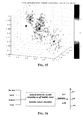
- Figures 12 and 13 are graphic representations obtained by simulations of values of clustering factor in function of the number of samples on which parameters are averaged, for random and deterministic initialization of cluster centers, respectively.
- the maximum value of the "clustering factor" is attained for a number of the pressure cycles, on which each input parameter is to be averaged, equal to 16. Therefore, the characteristic parameters are best averaged on 16 pressure cycles, because this number better fits the clustering requested by the user.
- evolutionary algorithms are used to search the optimal design of a neural network model, which emulates an on-off lambda sensor.
- the clustering process of data sets depends on the scaling of data values.
- Figures 14 and 15 show the difference of the results that were obtained by the same algorithm executed on two different data sets.
- data ⁇ , Pratio40 and Pratio50 values
- ⁇ values are in [0.8, 1.2].
- the same data are normalized in [0, 1].
- the six clusters, selected by the clustering algorithm for the first data set, are arranged along Pratio40 axis.
- the four clusters selected by the algorithm in the second data set are arranged along the ⁇ axis and they correspond to the three lambda values ranges useful to the setting-up of a VLS model: rich mixture range (orange and green cluster), stoichiometric range (brown cluster) and lean mixture range (blue cluster).
- rich mixture range range and green cluster
- stoichiometric range brown cluster
- lean mixture range blue cluster
- a model which emulates effectively a real lambda sensor, must distinguish the three regions above mentioned in the input space. In this way, the model is almost able to forecast if the engine is above or below the stoichiometric region (i.e. emulation of an on-off lambda sensor).
- the FCM could be chosen for decreasing the computing time.
- the cluster centers initialization could slow down the algorithm convergence velocity.
- clustering algorithms In practice, there are several critical factors that limit the use of the clustering algorithms for data pre-processing in real time systems. On the other side, clustering algorithms remain an important tool for pre-processing data for the off-line learning of models, e.g. models having applications in the automotive field.
- the learning machine is based on a new kind of working logic, substantially different from that of models proposed by R.J. Howlett et al.: such a learning machine is herein referred as Multi-Spread Probabilistic Neural Network.
- the model forecast capability is significantly lower than the forecast capability that the prior art models have in their working regions.
- the model of this invention has an outstanding forecast capability that is not tied bounded to a particular speed of engine nor to any particular position of the throttle.
- a neural network with a scalar output can be described as an hyper-surface ⁇ in R m+ 1 space, that is a map s: R m ⁇ R 1 .
- the index m represents design space dimension.
- Neural network design can be described as a multivariable interpolation in high dimensional space.
- i 1,2,..., N ⁇ is a set of N arbitrary nonlinear functions, known as radial basis function, the symbol ⁇ denotes a norm, that is usually Euclidean, and the points x (i) are the centers of these functions.
- Figure 18 depicts the architecture of the neural network RBF described by M.J.D. Powell equation (18).
- ⁇ ⁇ w d
- RBF-PNN Probabilistic Neural Network
- a classification problem can be formalized in the following way. Given a set of points ⁇ X ⁇ R m
- Matrix element U ik represents the probability that the i -th point belongs to c -th cluster. Usually, matrix elements U ik satisfy some normalization conditions.
- Figure 19 shows the typical architecture of a RBF neural network.
- this scheme after the hidden layer there is a block which computes membership matrix elements corresponding to input vector.
- the winner takes all neurons".
- hidden layer neurons outputs hence we assign to the input vector the membership class of hidden layer neurons which has the largest output.
- Hidden layer neurons outputs depend on the distance of the input vector from the centers of radial basis functions and on spreads of the same functions.
- N is the number of vectors used for testing of neural network model while N 1 is the number of neurons of the hidden layer; usually, the last matches the number of samples used for neural network training.
- S k which is related to Gaussian function variance, represents the so-called "spread" factor.
- the points x (*) satisfying eq. (23) describe a hypersphere, having the center in x (k) , whose radius increases as S k values decrease.
- this threshold is equal to 0.5
- this threshold is equal to 0.5
- RBF-PNN neural networks have two limitations: they use the same spread factor for each neuron of hidden layer and they have not an explicit and definite procedure to determine the optimal value of S k according to the current classification problem.
- MultiSpread-PNN overcomes the above noted two limitations of known models.
- Figure 20 compares graphically a RBF-PNN and a MultiSpread-PNN neural network of this invention.
- the spheres represent a three-dimensional section of hyperspheres, having unitary ray, by which the R m subspace can be described from which the model inputs are extracted.
- the N 1 spread factors of MultiSpread PNN are endogenous parameters of the model. Research space of these parameters is R [ 0 , 1 ] N 1 , where the symbol R [0,1] represents real numbers in the compact range [0, 1].
- EA Evolution Strategy
- PSOA Particle Swarm Optimization Algorithm
- DE Differential Evolution algorithm
- a trivial choice of the fitness function could be the classification error on testing data set of the MultiSpread-PNN model. In so doing, a "generalized” estimate of the endogenous parameters of model cannot be obtained. "Generalized” estimate means that the choice of the endogenous parameters of a model is made to increase model generalization capability, that is model “generalized forecast capability” [17].
- the formula (24) derives from generalization of the "ordinary cross-validation estimate" of endogenous parameters of a neural network (chapter 5 of [18], and [19]).
- the parameter N * is the number of possible choices of a testing set with N samples in a data set composed by N + N 1 input output couples.
- k i labels the N elements of testing data set selected with the i -th choice.
- MultiSpread-PNN output is described by the symbol F ( S 1 , S 2 , ... S N 1 ) i .
- the optimal string of spread factors is the one which minimizes the functional V 0 ( S 1 , S 2 ,..., S N 1 ). To search this minimum, the above mentioned evolutionary algorithms were used.
- Figures 21 and 22 show the results obtained by the best RBF-PNN and MultiSpread-PNN, respectively.
- the models were trained and tested on the Hyundai engine data set. These preliminary outcomes suggest that in the sensible lambda values ranges, where a satisfactory real lambda sensor is practically infallible, virtual emulator of an on-off lambda sensor according to the model of this invention fails about just one time over 100 estimates. In other words, this means that in the sensible lambda values ranges, the neural network models that have been found have a classification rate of about 99%.
- Figure 23 shows a performance comparison between RBF-PNN and MultiSpread PNN on 25 random permutations of the Hyundai data set.
- model classification error was compared for, on the whole range of lambda values, related only to the testing data set.
- the classification error averages to 4,22% while for the classical RBF-PNN, the classification error averages to 5.13%.
- the novel model By having as inputs engine speed and inlet manifold pressure, the novel model has a forecast capability that is not limited to a single engine speed and/or a single throttle position.
- the novel model is defined through a data pre-processing that establishes the optimal number of instantaneous cycles to be averaged for maximizing the correlation between MultiSpread-PNN model inputs and outputs.
- the novel MultiSpread-PNN model has on average a larger forecast capability for the same set-up computational complexity.
- a neural network model as the novel MultiSpread-PNN can be simply implemented with a low cost micro-controller.
- the model can be downloaded on the micro-controller memory as a sequence of matrices.
- Computational cost for a real-time application of the MultiSpread-PNN would be equal to the time that micro-controller spends to perform simple matrices products.
- the only limitation of the MultiSpread-PNN model for real-time applications is related to the number of successive pressure cycles (16) over which input parameters must be averaged for maximizing the correlation between inputs and outputs.
- the control system has a delay equivalent to 16 pressure cycles.
- Figure 24 is a block diagram scheme of a feedforward-and-feedback control system employing a virtual lambda sensor of this invention.
- the system is composed of a feedforward controller A, a pressure sensor, a device of this invention C for sensing the air/fuel ratio and a feedback controller B.
- the feedforward controller A is input with signals representative of the speed and of the load of the engine, and outputs a signal DI FF , that represents a duration of the fuel injection of the engine, and a spark generation control signal SA, that determines the spark-advance of the engine.
- the levels of these signals DI FF and SA are calculated by the feedforward controller A in function of the current speed and load of the engine using a pre-determined model of the engine.
- the feedback controller B generates a feedback signal DI FB for correcting the calculated fuel injection duration, represented by the signal DI FF , in function of the difference between the signal generated by the virtual lambda sensor C of this invention and a reference value REF.
- This block generates the signals SA and DI FF in function of the speed and load of the engine by using control maps of the engine.
- a mathematical model of the functioning of the engine is determined during a test phase in order to determine, for any pair of values of speed and load of the engine, the best values of the duration of the fuel injection and the spark-advance of the engine.
- the feedforward controller A compares the input values of speed and load with those stored in a look-up table generated during a test phase of the engine, and outputs the signals DI FF and SA of corresponding values. When the input values of the speed and load do not correspond to any pair of the look-up table, the feedfoward controller A calculates the levels of the signals DI FF and SA by linear interpolation.
- the calculated duration of fuel injection represented by the signal DI FF is corrected by a feedback signal DI FB generated in function of the sensed air/fuel ratio of the engine.
- the feedback controller B generates a feedback signal for correcting the duration of fuel injection calculated by the feedforward controller A, in function of the difference between the signal output by the virtual lambda sensor of this invention ⁇ and a reference value REF.
- the feedback controller B comprises an error evaluation subsystem B1 and a correction subsystem B2.
- FIG. 25 A sample embodiment of the error evaluation subsystem B 1 is shown in Figure 25.
- the correction subsystem B2 is preferably composed of a correction unit CONTROLLER and an output stage, as shown in Figure 26.
- the correction unit CONTROLLER is input with the signals ERROR and C_ERROR and generates, in function thereof, a correction signal ⁇ _DI of the feedback signal DI FB in order to nullify its input signals ERROR and C_ERROR.
- the correction unit CONTROLLER is a fuzzy logic unit with two antecedents, that are the normalized values EN and CEN of the signals ERROR and C_ERROR, respectively, and one consequent, that is the normalized value OUTPUT 1 of the correction signal ⁇ _DI, and preferably it is defined by three membership functions for each antecedent and consequent.
- Figure 27 shows sample membership functions E_N, E_Z and E_P when the antecedent EN is negative, null (in a fuzzy sense) or is positive, respectively.
- Figures 28 and 29 show sample membership functions for the antecedent CEN and the consequent OUTPUT1, respectively.
- the fuzzy correction unit CONTROLLER generates the correction signal ⁇ _DI according to the nine fuzzy rules shown in Figure 30. These fuzzy rules are graphically illustrated in Figure 31 and in the tree-dimensional graph of Figure 32.
- the output stage of the correction subsystem B2 is preferably composed of an amplifier N 3 of the correction signal ⁇ _DI, and of a positive feedback loop that generates the feedback signal DI FB by adding to the amplified correction signal ⁇ _DI a delayed replica thereof ⁇ _DI(T- ⁇ T 2 ) of a certain time delay ⁇ T 2 :
- I D F B N 3 ⁇ ⁇ _ D I ( T ) + ⁇ _ D I ( T ⁇ ⁇ T )
- the learning machine C includes an identification subsystem C2 that chooses the smallest number of characteristic parameters of the detected pressure signal sufficient for estimating the value of the air/fuel ratio.
- the subsystem C2 is input with the pressure signal generated by the pressure sensor in contact with at least a cylinder of the engine and implements a clustering algorithm for choosing moving averages of these characteristic parameters.
- the identification subsystem C2 generates data sets composed of values of moving averages of characteristic parameters of a certain initial set of parameters, that are potentially useful for evaluating the air/fuel ratio, each for a respective number of pressure cycles. In function of the desired number of clusters, it groups in clusters the moving averages of each data set with a respective execution of a clustering algorithm. Then, the number of pressure cycles on which these moving averages are calculated is chosen as the number corresponding to the execution of the clustering algorithm for which the ratio between the clustering performance index and the ideal clustering performance index is maximum.
- the clustering method thus allows to choose the best number of pressure cycles for averaging these characteristic parameters in order to evaluate the lambda factor, as schematically illustrated in Figure 33.
- the core C1 of the lambda sensor of this invention is input with the parameters chosen by the identification subsystem C2.
- the selected characteristic parameters of the pressure signal are the pressure Pratio40 in a cylinder for a 40° rotation of the crank, the pressure Pratio50 in a cylinder for a 50° rotation of the crank, and the pressure peak Pmax independently from the position of the crank at which it is attained.
- the core of the lambda sensor may either be a neural network, a stochastic machine, a support vector machine, a committee machine or a hybrid learning machine.
- the most performing cores are composed of a neural network or a hybrid learning machine.
- Figure 35 shows a block scheme of a lambda sensor core based on a neural network.
- the preferred inputs of the core are the parameters Pratio40, Pratio 50 and Pmax, that are the characteristic parameters of the pressure signal that more often have been chosen by the identification subsystem C2 during the extensive tests that were carried out.
- Signals representative of these parameters are processed by an input stage EDGE DETECTOR, for sampling the input signals and generating a synchronization pulse for the subsequent blocks in cascade.
- the instant at which the synchronization pulse is generated is determined in function of the instant at which a pressure peak is detected. Indeed, it has been experimentally verified that this instant is sufficiently stable and relatively free of spurious variations.
- the block PRE-PROC is a pre-processor that generates a moving average of the data output by the input stage EDGE DETECTOR, for filtering these data from noise.
- the number of samples to be considered for calculating the moving average which is a number of pressure cycles of the engine, must be established. This number should not be too large, because this would make the virtual lambda sensor less prompt in reacting to functioning variations of the engine, nor too small, otherwise the level of noise corrupting the moving average would be too high.
- the block POST-PROC is a post-processor analogous to the pre-processor PRE-PROC.
- the pre-processor and the post-processor effectively reduce the noise corrupting the output signal of the virtual lambda sensor core, as may be easily inferred by comparing the graphs in Figures 36a and 36b of the output signal with and without the blocks PRE-PROC and POST-PROC, respectively.
- the learning part NEURAL NETWORK of the virtual lambda sensor core is a neural network, preferably a MLP (Multi Layer Perceptron) with three inputs, thirty neurons in the hidden layer and a single output.
- the number of neurons has been chosen by a so-called "ordinary cross-validation" procedure with single-objective and multi-objectives optimization.
- the neural network may be trained with classic learning algorithms, such as the "resilient back propagation” algorithm and/or the Levenberg-Marquardt algorithm, and stochastic search algorithm, such as the Particle Swarm Optimization Algorithm (PSOA).
- classic learning algorithms such as the "resilient back propagation” algorithm and/or the Levenberg-Marquardt algorithm
- stochastic search algorithm such as the Particle Swarm Optimization Algorithm (PSOA).
- PSOA Particle Swarm Optimization Algorithm
- FIG. 37 An embodiment of the core of the virtual lambda sensor that includes a so-called “committee machine” is shown in Figure 37. It includes an input stage EDGE DETECTOR, a pre-processor PRE-PROC and three post-processors POST-PROC that are identical to the homologous blocks of Figure 35.
- the embodiment of Figure 37 comprises three fuzzy subsystems LEAN FIS, ON-OFF FIS and RICH FIS, that are typically "TSK Singleton" fuzzy inference subsystems, that are defined by different parameters and generate respective signals related to the air/fuel ratio of the engine for ⁇ ⁇ 1, ⁇ > 1 and ⁇ ⁇ 1, respectively.
- the fuzzy subsystem ON-OFF FIS works like an on/off lambda sensor.
- An output multiplexer SWITCH generate an output signal OUTPUT2 that is the signal generated by the subsystem LEAN FIS or RICH FIS depending on the value of the output of the ON-OFF FIS subsystem. Even this last signal is made available (OUTPUT1), thus the virtual lambda sensor core of Figure 37 may function either as a linear lambda sensor (OUTPUT2) or as an on/off lambda sensor (OUTPUT1).
- Each fuzzy subsystem has three antecedents and one consequent and preferably is defined by three membership functions for each antecedent or consequent.
- the fuzzy subsystems are trained using experimental data with a "supervised training" procedure implementing a stochastic search algorithm (such as a PSOA) for calculating optimal values to be assigned to the parameters of the membership functions, the crisp values and the like.
- a stochastic search algorithm such as a PSOA
- the fuzzy subsystem RICH FIS is trained such that the output signal preferably ranges between 0.85 and 0.98, while the fuzzy subsystem LEAN FIS outputs a signal that ranges between 1.02 and 1.15.
- the fuzzy subsystem ON-OFF FIS is trained for estimating very accurately the air/fuel ratio for 0.98 ⁇ ⁇ ⁇ 1.02 . An eventual error in this range would make the output multiplexer SWITCH select the output of the subsystem LEAN FIS when the air/fuel mixture is reach or vice versa.
- the pre-processor and the post-processors filter the noise that may corrupt signals input to and output from the fuzzy subsystems. They are useful because spurious spikes corrupting the signal output by the subsystems could degrade relevantly the accuracy of the sensing of the air/fuel ratio. In particular, spurious spikes output by the ON-OFF FIS subsystem must be filtered because they could induce spurious switching of the multiplexer.
- the virtual device of this invention for sensing the air/fuel ratio has numerous advantages.
- the device of this invention need not warming up for functioning correctly, has a relatively low cost and tracks the air/fuel ratio very quickly.
- lambda sensors such as the lambda sensor HEGO
- HEGO the lambda sensor
- their accuracy is limited by the fact that they are installed in the exhaust gas pipe of the engine, which means that they cannot generate a signal representing the air/fuel ratio before the exhaust gases reach the sensor. Therefore, classic lambda sensors are generally sluggish in responding to rapid changes of the functioning conditions of the engine.
- Formula 1 cars often damage their exhaust gases pipes where the lambda sensors are installed. In these situations, a classic lambda sensor may not sense correctly the air/fuel ratio and the engine risks to be miscontrolled.
- the feedforward-and-feedback control system of this invention has been real-time tested on the Hyundai engine YP125.
- a closed lop injection control system based on soft computing models was realized.
- the loop included a Virtual Lambda Sensor and control system of this invention.
- Figure 38 describes the time-changing trend of the lambda values as sensed by a real lambda sensor when the control system of this invention was activated, in order to test its performances.
- the engine is effectively maintained close to the stoichiometric condition with an error smaller than 1%.
- control system of this invention was tested under different transient conditions. After few seconds, the control system brought back the engine to stoichiometric combustion conditions within 1% error.
- Figures 41, 42 and 43 illustrate the results of these tests under transient conditions.
- Figure 44 depicts the test console for simulating the functioning of the engine controlled by the system of this invention at 4600 rpm and WOT condition.
- Figures 45 and 46 depict the test console when the feedforward-and-feedback control system of the engine had restored stoichiometric conditions ( ⁇ ⁇ 1) starting from a condition in which the engine in working with a rich mixture ( ⁇ ⁇ 1) and with a lean mixture ( ⁇ >1), respectively.
Abstract
Description
- This invention relates to control systems of the operating parameters of internal combustion engines and more particularly to a method and relative device for sensing the air/fuel ratio (briefly AFR) of an internal combustion engine, and a relative control system that uses this sensing device.
- In the last twenty years, fundamentals goals of engine manufacturers are to achieve significant reductions of the amounts of pollutants emitted at the engine exhaust and a lower fuel consumption without compromising speed and torque performances. For these reasons, an efficient engine control based on a comprehensive monitoring of the many engine working parameters is required.
- To maintain a strict control of the engine working parameters Engine Management Systems (EMS) or Engine Control Units (ECU) are used. The EMS implements control strategies which achieve the optimum trade-off between several contradictory objectives: high output power when required by driver, low emission levels and low fuel consumptions. At the same time, in a spark-ignition engine, the EMS must bring and maintain the engine in a specified operating range such that the three-way catalytic converter can further reduce the harmful content of the exhaust gases. The EMS controls the amount of fuel injected in the engine combustion chamber (fuel pulse width), the point in the engine cycle at which the mixture air fuel is ignited (ignition timing) and in advanced engine designs, other parameters, such as the valve timings. The EMS determines values for these parameters from measured quantities such as speed, torque, air mass flow rate, inlet-manifold pressure, temperatures at several critical points and throttle angle.
- Figure 1 illustrates the EMS function. EMS must determine values for Controlled Variables from a knowledge of the Measured Variables in order to achieve the Systems Aims. EMS is essentially composed by three components: engine maps (look-up tables stored in a ROM), controller and sensors, as schematically depicted in Figure 2.
- In addition to sensors for measuring quantities of interest, such as speed, manifold pressure, air mass flow rate, temperature (that is, the Measured Variables appearing in both Figures 1 and 2), in Figure 2 appear other sensors too. These additional devices monitor whether the engine is working according to the Systems Aims, or not. Therefore, they have an active part in the real time updating process of controlled variables and, eventually of the engine maps. For example, in a spark-ignition engine a sensor of this type is the so-called lambda sensor. The lambda sensor mounted in the exhaust stream, as schematically shown in the block diagram of Figure 3, determines whether the lambda ratio (that is AFR/AFR stoichiometric ) is above or below unity from the amount of oxygen detected in the exhaust gas mixture. The EMS uses this information to adjust the fuel pulse width and/or the ignition timing to keep the lambda ratio as close as possible to unity.
- In order to keep the air/fuel ratio (AFR) within such a narrow range, a lambda sensor is inserted in the outlet of exhaust gases for monitoring the amount of oxygen in the exhaust gases. The lambda sensor provides a signal representative of the value of the ratio

- If λ < 1 the mixture is rich of fuel, while if λ > 1 the mixture is lean of fuel, as schematically shown in Figure 4.
- The signal generated by the lambda sensor is input to the controller of the engine that adjusts the injection times and thus the fuel injected during each cycle for reaching the condition λ= 1.
- Many lambda sensors actually available, the so-called on/off lambda sensors, do not evaluate the title of the mixture and thus the exact value of λ, but signal whether the mixture is reach or lean. Considering that the injection time should ideally be proportional to the air/fuel ratio, these on/off lambda sensors do not allow a precise regulation.
- There are lambda sensors that generate a signal representative of the effective value of the air/fuel ratio, but these lambda sensors (the so-called "wide-band lambda sensors") are either very expensive or not very accurate. The following table compares costs and accuracies of commercially available "wide-band lambda sensors":
accuracy for lean mixtures accuracy for stoichiometric mixtures accuracy for rich mixtures cost (USD) McLaren electronic systems 1.7% 0.1% 1.7% 1500-1800 MoTeC 2.5% 1.75% 1.75% 800-900 Bosch LSM 11 1.5% unknown unknown 300-400 Horiba LD-700 8.0% 4.0% 8.0% 60-80 - Engines manufacturers are generally reluctant to a proliferation of sensors unless they produce sensible improvements that could not otherwise attained. Virtual-sensors techniques are generally welcome because of their comparability lower cost reliability and sturdiness. Virtual-sensors allow quantities estimates of interest without the necessity for sensors dedicated to the measurements. In this field, intelligent systems models, such as neural networks, are attractive because of their capabilities in pattern recognition and signal analysis problems [1].
- An approach to realize a virtual lambda sensor uses neural networks to correlate certain features of spark plug voltage waveforms with specific values of air fuel ratio [2], [3]. The spark plug is in direct contact with the combustion processes which are occurring in the engine cylinder, hence analysis of the spark plug voltage waveforms seems to be potentially a suitable method of monitoring combustion in spark ignition engines.
- There are essentially two methods of using spark plug as a combustion sensor, namely: the Ionic-Current and Spark Voltage Characterization (SVC) methods. In the ionic-current system, the spark plug is used as a sensor during the "non-firing" phase of the pressure cycle, which is the part of the pressure cycle after the spark advance, that is, after the spark ignition. This is done by applying a small voltage of about 100 Volts to the spark plug and measuring the current. The current is supported by reactive ions in the flame that carry on ionic current across the spark plug gap. The type and the number of ions, formed during and after the combustion, depends on the combustion conditions. The Ionic-Current depends also on other parameters such as temperature, pressure and other. Recently, much work has been done on the use of Ionic-Current for monitoring combustion [4], [5], [6], [7].
- The SVC method rests on the analysis of the time-varying voltage detected across the gap of the spark plug. Since the SVC method involves the analysis of the ignition voltage waveform itself, it does not require additional biasing means and associated high voltage switching circuitry.
- Figure 5 illustrates a typical spark voltage waveform. The shape of spark voltage waveform has several predictable phases. When the EHT (Extra High Tension) pulse is generated, the potential difference across the gap rises up to 12kV and breakdown occurs. Breakdown is a fall in voltage that produces a characteristic voltage spike of about 10µs in duration. Thereafter, a glow-discharge tail region of the waveform of a few milliseconds duration appears. Tests have demonstrated that changes of engine working parameters lead to changes of the shape of certain features of the waveform. However, it is far from being easy to predict these variations as the engine parameters are varied; in fact, random variations occur between successive sparks even when engine working parameters are kept constant.
- Interactions of parameters, such as combustion temperatures, compression, composition of the air-fuel gas mixture, affect the shape of the breakdown voltage spike in the spark voltage waveform. Changes of the lambda ratio lead to breakdown voltage changes and to subtle changes in the overall shape of the ignition spark waveform. Lambda ratio changes appear to affect both the shapes of the breakdown voltage spike and of the flow-discharge tail portion of the waveform. An analytic relationship between lambda values and instantaneous voltage values of the spark voltage waveforms has not been found yet. However, several articles ([8] and [9]) sustain a correlation between the vector formed through a periodic sampling of the spark plug voltage (spark-voltage vector) and lambda values.
- The Spark Voltage Characterization (SVC) technique is based on setting up an effective neural network for associating the spark-voltage vector and lambda ratio.
- According to R.J. Howlett et al. in [8] [9] and [10], it is possible to design a Virtual Lambda Sensor, that is a device for sensing the air/fuel without analyzing the exhaust gases of the engine.
- Such a virtual sensor is based on a neural network trained to find the best correlation between characteristic aspects of the spark voltage waveform and lambda values. The trained neural network determines, for a current vector of characteristic values of the spark voltage, whether the air/fuel ratio (lambda value) is in the stoichiometric mixture range or in lean or rich mixture ranges.
- Figure 6 shows a typical experimental arrangement to acquire data for training of virtual lambda sensor models. The dynamometer, by which engine "dummy" load may be varied as desired, is used to measure load-torque and to calculate the output power. Setting of throttle position and fuel pulse width allows to change air-fuel ratio; in this way, a data set related to the whole range of lambda values may be established.
- The blocks EMU, A-D converter and DSP are an Engine Management Unit, Analog-to-Digital converter and Digital Signal Processor, respectively.
- Air-fuel ratio values are measured by an exhaust gas analyzer. To measure spark plug voltage the ignition system is modified by the addition of an high-voltage test-probe at the spark plug.
- In these approaches, a MLP (Multiple Layer Perceptron) neural network, with a single hidden layer and sigmoidal activation units, is used as a spark-voltage vector classifier.
- In a supervised training paradigm, a back-propagation learning algorithm sets the MLP training. The training file contains N t pairs input-output; model input is an instantaneous spark-voltage vector of the form V i =(ν1, ν2,...,ν m ), with i = 1, ..., N t and m equal to the length of the spark-voltage vector; model output is a desired output vector of the form D r = (0,0,1), D stoi = (0,1,0) and D t = (1,0,0), depending on whether the lambda value, associated to the current spark-voltage vector, is rich (<1), stoichiometric (≈1) or lean (>1).
- Three sets of spark-voltage vectors and their associated desired output vectors build the training file. Similar files, built by data that must not be used for training, are created for validation and test purposes. In this case, during the testing phase, to estimate the model forecast capability is sufficient to count the number of times in which model output doesn't match the desired output value; the ratio between this number and the total number of estimates represents the model classification error. An alternative quantity for describing the model forecast capability can be simply obtained as difference between 1 and the classification error. This alternative quantity is usually called correct classification rate.
- R.J. Howlett et al. [8] [9] carried out a multi-speed test with the same 92cc single-cylinder four-stroke engine. In this case, they used a more closely-spaced range of lambda values, i.e. 0.9, 1.0 and 1.1. Figure 7 shows the trend of the correct classification rate of the virtual lambda sensor model versus engine speed for various model training file sizes. The normalized size of the training file σ, used in this test, satisfies the following relationship N t = N w σ, where N t is the size of training file and N w is the number of weights of the MLP neural network modeling virtual lambda sensor.
- These approaches have important drawbacks.
- The above virtual lambda sensors are unable to indicate the actual AFR but only if the AFR is in one or the other range. In other words, they cannot confirm lambda values approximately equal to 0.95 or 1.05 (re: blue rectangles in Figure 8).
- The number of cycles of integration, according to the approach aimed at reducing the effect of random variations observed in successive spark waveforms is not specified. However, this would be an important parameter when realizing a fast gasoline engine injection control system.
- The forecast capability of the system of R.J. Howlett et al. [8-9] has a strong dependence on engine speed.
- It has been shown [20] that at MBT condition (Maximum spark advance, evaluated in respect to the TDC for the Best Torque) the pressure peak in a cylinder during combustion is correlated with the air/fuel ratio, while the location of the pressure peak at a fixed air/fuel ratio value is correlated with the spark advance. Therefore, it is possible to regulate the air/fuel ratio at stoichiometric conditions simply by correcting the fuel injection in order to keep constant the position of the crank at which the pressure peak is attained and keeping the pressure peak at a certain value.
- The so-called MBT condition is the operating condition of the engine when the spark advance takes on the maximum value before bringing the engine toward the knocking phenomena. Normally, this condition is not often verified during the functioning of the engine.
- In [20], a neural network for sensing the position of the crank when the pressure peak occurs (that is the Location of the Pressure Peak, or briefly the LPP parameter) and the pressure peak value (briefly, the PP parameter) is also disclosed. This neural network is embodied in an air/fuel ratio feedback regulator, and provides to a control system of the engine signals representing the LPP and the PP parameters. This control system drives the motor in order to keep constant the LPP parameter and to keep constant the air/fuel ratio by regulating the pressure peak in the cylinders.
- Unfortunately, this document though establishing that there is only a relationship between the air/fuel ratio and the pressure peak if the LPP parameter of the motor is constant (in particular, if the LPP parameter corresponds to the value for MBT condition), is silent about any possibility of assessing the actual air/fuel ratio in function of the pressure peak without employing a classic lambda sensor under any condition of operation of the engine.
- As a matter of fact, the correlation between the pressure peak and the air/fuel ratio has been demonstrated only in steady-states at certain operating conditions, that is, at MBT conditions, at 2000rpm and MAP of 0.5 and 0.8 bar.
- The system disclosed in that document does not lend itself for sensing the air/fuel ratio, that is for generating a signal that represents at each instant the current value of the air/fuel ratio of the engine.
- Therefore, the need remains for a low cost manner of sensing the air/fuel ratio with a sufficient accuracy under any condition of operation of the engine.
- It has been found a method of sensing the air/fuel ratio in a combustion chamber of an internal combustion engine that may be easily implemented by a respective low-cost device.
- The device of the invention has a pressure sensor and a learning machine that generates a sensing signal representing the air/fuel ratio by processing the waveform of the pressure in at least a cylinder of the engine. In practice, the learning machine extracts characteristic parameters of the waveform of the pressure and in function of a certain number of them generates the sensing signal.
- Surprisingly, the device of this invention is even more accurate of the classic lambda sensors in any operating condition of the engine.
- The characteristic parameters to be used for sensing the air/fuel ratio are preferably averaged on a certain number of pressure cycles, for reducing noise and improving the accuracy of the sensing. This certain number of pressure cycles is established by using a clustering algorithm on a data set composed of various moving averages of these parameters carried out on different number of pressure cycles.
- According to an innovative aspect of this invention, the learning machine of the device of this invention for sensing the air/fuel ratio is based on a novel kind of neural network, herein referred as MultiSpread-PNN. An appropriate method of training such a neural network is also disclosed.
- The device of the invention is conveniently inserted in a feedforward-and-feedback control system of an engine for regulating its air/fuel ratio at the stoichiometric value.
- All the methods of this invention may be implemented by a software computer program.
- The invention is defined in the annexed claims.
- The different aspects and advantages of the invention will become even clearer through a detailed description of practical embodiments referring to the attached drawings, wherein:
- Figure 1 is a block diagram that illustrates schematically a control of an internal combustion engine by means of an Engine Management System;
- Figure 2 is a block diagram of an Engine Management System;
- Figure 3 illustrates an Engine Management System for a spark ignition engine;
- Figure 4 is a graph that illustrates the conversion percentages of exhaust gases of the engine in function of the air/fuel ratio;
- Figure 5 depicts a simple spark voltage waveform of an internal combustion engine;
- Figure 6 depicts an arrangement for training a lambda sensor based on a neural network;
- Figure 7 illustrates how the correct classification rate of the lambda sensor of Figure 6 varies in function of the engine speed;
- Figure 8 shows schematically how a Multi-Layer Perceptron neural network of Figure 6 determines the air/fuel ratio of an internal combustion engine;
- Figure 9 depicts an arrangement of this invention for training a lambda sensor based on a learning machine;
- Figure 10a to 10d are graphs that show results of a clustering algorithm on the values of the parameter Pratio40 sensed at each pressure cycle, averaged on five, ten and fifteen pressure cycles, respectively;
- Figure 11 is a sample graph of the performance index of a chosen clustering algorithm in function of the number of clusters in which data are grouped;
- Figure 12 is a sample graph of the clustering factor of a chosen clustering algorithm in function of the number of samples used for calculating the moving averages on which the clustering algorithm is applied, for random initializations of the centers of the clusters;
- Figure 13 is a sample graph of the clustering factor of a chosen clustering algorithm in function of the number of samples used for calculating the moving averages on which the clustering algorithm is applied, for deterministic initializations of the centers of the clusters;
- Figure 14 is a graph showing a sample result of a chosen clustering algorithm on moving averages of the values of the parameters Pratio40, Pratio50 and on the value lambda of the air/fuel ratio;
- Figure 15 is a graph normalized in the range [0; 1] showing a sample result of a chosen clustering algorithm on moving averages of the values of the parameters Pratio40,
Pratio 50 and on the value lambda of the air/fuel ratio; - Figure 16 shows schematically how a device of this invention based on a neural network of Figure 9 for sensing the air/fuel ratio of an internal combustion engine works;
- Figure 17 highlights the incertitude range of the device of the invention
- Figure 18 depicts a typical architecture of a classic RBF neural network;
- Figure 19 depicts a typical architecture of a classic RBF-PNN neural network;
- Figure 20 compares a classic RBF-PNN neural network with a MultiSpread-PNN neural network of this invention;
- Figures 21 and 22 show test results obtained with a known RBF-PNN neural network and a MultiSpread-PNN neural network of this invention for sensing the air/fuel ratio of an engine;
- Figure 23 compares the mean test errors of the neural networks of Figures 21 and 22 in function of the number of times in which the neural networks RBF-PNN and MultiSpread-PNN have been trained, validated and tested on different training, validation and testing data sets;
- Figure 24 shows a feedforward-and-feedback control system of this invention that uses a device of this invention for sensing the air/fuel ratio of the engine;
- Figure 25 shows a sample embodiment of the error evaluation subsystem B1 of Figure 24;
- Figure 26 shows a sample embodiment of the correction subsystem B2 of Figure 24;
- Figures 27 to 29 show sample membership functions for the inputs and output of the correction unit CONTROLLER of Figure 26;
- Figure 30 shows the nine fuzzy rules of the correction unit CONTROLLER of Figure 26;
- Figures 31 and 32 are graphs that describe the fuzzy rules of the correction unit CONTROLLER of Figure 26;
- Figure 33 illustrates schematically how the parameters for training the learning machine of the device of this invention are chosen;
- Figure 34 illustrates schematically embodiments of the device of this invention for sensing the air/fuel ratio;
- Figure 35 shows an embodiment of the device of this invention based on a neural network;
- Figures 36a and 36b compare sample graphs of the output generated by the device of Figure 35 without and with the pre-processor and the post-processor, respectively;
- Figure 37 shows an embodiment of the device of this invention based on three fuzzy subsystems;
- Figure 38 is a graph of sensed values of the air/fuel ratio during a test in which an engine in steady state at 4600rpm and WOT condition was controlled by the feedforward-and-feedback control system of this invention;
- Figure 39 is a graph of sensed values of the air/fuel ratio during a test in which an engine in steady state at less than 4600rpm and throttle not in WOT condition was controlled by the feedforward-and-feedback control system of this invention;
- Figure 40 is a graph of sensed values of the air/fuel ratio during a test in which an engine in steady state at 4600rpm and torque of 1.5Nm was controlled by the feedforward-and-feedback control system of this invention;
- Figure 41 is a graph of sensed values of the air/fuel ratio during tests in which an engine in transient conditions after variations of the throttle position from 38% to 100% was controlled by the feedforward-and-feedback control system of this invention;
- Figure 42 is a graph of sensed values of the air/fuel ratio during a test in which an engine in transient conditions at 4600rpm and WOT condition was controlled by the feedforward-and-feedback control system of this invention;
- Figure 43 is a graph of sensed values of the air/fuel ratio during a test in which an engine initially functioning with lean mixtures was controlled by the feedforward-and-feedback control system of this invention;
- Figure 44 displays the software console of the used test system during a test in which an engine in a steady state at 4600rpm and WOT condition was controlled by the feedforward-and-feedback control system of this invention;
- Figures 45 and 46 display the software console of the used test system during a test in which an engine in transient conditions at 5596rpm and 4605rpm, respectively, was controlled by the feedforward-and-feedback control system of this invention.
- According to this invention, the inputs for modeling a virtual lambda sensor are obtained from an engine cylinder pressure signal generated by a pressure sensor, such as for instance the integrated pressure sensor disclosed in [21].
- According to the invention, a virtual device capable of sensing the air/fuel ratio is based on a learning machine trained according to the scheme of Figure 9.
- Of course, it is possible to train the learning machine using also characteristics of other signals (the speed of the engine, for instance) in addition to the characteristics of the waveform of the pressure in a cylinder, but surprisingly it has been found that the pressure waveform features alone permit to achieve an outstandingly accurate assessment of the air/fuel ratio.
- Indeed, a wealth of operating parameters of the engine could be extracted from the waveform of pressure in a cylinder. Of course, it is not convenient to consider all of them because the computational load of the learning machine would become excessive.
- A sample set of characteristic parameters that are correlated with the air/fuel ratio are resumed in the following table
unit of measure element description Speed rpm engine speed lambda [ ] lambda values Aircycle mg/cycle air massive flow BstMap bar intake manifold pressure BurDur deg combustion duration pEVC bar pressure at exhaust valve closure pEVO bar pressure at exhaust valve opening pIVC bar pressure at intake valve closure pIVO bar pressure at intake valve opening Pratio40 [ ] pressure ratio between pressures at 40 crank angles before and after TDC Pratio50 [ ] pressure ratio between pressures at 50 crank angles before and after TDC Pratio60 [ ] pressure ratio between pressures at 60 crank angles before and after TDC Pratio70 [ ] pressure ratio between pressures at 70 crank angles before and after TDC Pratio80 [ ] pressure ratio between pressures at 80 crank angles before and after TDC Pratio90 [ ] pressure ratio between pressures at 90 crank angles before and after TDC Pratio100 [ ] pressure ratio between pressures at 100 crank angles before and after TDC Pratio110 [ ] pressure ratio between pressures at 110 crank angles before and after TDC Pmax bar maximum pressure PcompMax [ ] ratio between maximum of pressure cycle and maximum of pressure cycle without combustion - These parameters have been identified as relevant for estimating the air/fuel ratio during extensive tests carried out on the commercial scooter engine: Yamaha YP125 (four stroke spark ignition engine with a displacement of 125cc). The tests have been performed at several engine speeds, throttle positions, and spark advances, for considering all possible functioning conditions of the engine.
- Given that a learning machine processing detected relevant parameters for estimating the air/flow ratio would be relatively slow, a small number of parameters to be used has been chosen.
- A data pre-processing campaign was carried out to identify the parameters more correlated to the air/flow ratio (lambda value). During each pressure cycle all the above parameters were measured and the corresponding lambda value was sensed by a lambda sensor. The correlation of each parameter with the sensed air/fuel ratio was calculated, and only the three parameters that resulted most correlated with the air/fuel ratio as directly measured by the sensor were chosen as inputs of the learning machine.
- Of course, it is possible to choose more than three parameters or even two or only one parameter as inputs of the learning machine, but the choice of three parameters appeared a good compromise. While choosing to use a larger number of parameters will increase the computational load, a too small number of parameters may impair the accuracy under varying functioning conditions of the engine.
- The three parameters most correlated with the air/fuel ratio resulted to be Pratio40, Pratio50 and Pmax and, according to a preferred embodiment of this invention, these three parameters were used as the inputs of the learning machine.
- In view of the fact that the values of these parameters as detectable may be corrupted by noise, it is advisable to use a moving average of the parameter calculated over a certain number of pressure cycles for estimating the air/fuel ratio.
- A problem faced by the Applicants consisted in determining the number of detections values to be taken for calculating the moving average value to be used for the air/fuel ratio calculation. The larger is the number of successive samples, the more filtered from noise are the inputs of the learning machine, but the less prompt is the tracking of a time-changing air/fuel ratio.
- In order to find the most effective solution, numerous moving averages with different numbers of samples of the three parameters have been calculated, and the moving average that resulted most correlated with the air/fuel ratio was chosen through a clustering analysis, that will be described in detail in the next chapter.
- Figures 10a to 10d show the results of a clustering process carried out among moving averages of the parameter Pratio40 calculated over different numbers of samples, and the corresponding λ value. It was experimentally determined that the larger the number of samples over which the moving average is carried out, the larger is the correlation between Pratio40 and the corresponding λ value.
- In the graphs, each correlation is represented with a circle of pre-established radius and the circles of each cluster have the same color. From a mathematical point of view, this is equivalent to assume that small input variations generate small output variations, that is equivalent to assume that the air/fuel ratio depends on this parameter through a well-posed mathematical problem ([11], [12] and [13]).
- A more detailed description of the Yamaha engine data set clustering analysis is presented in the following chapter. A novel factor, called "clustering factor", to compare how different data sets fit an user requested clusters number has been used and it has been found that the moving averages should be carried out on 16 successive samples for obtaining the best trade-off between noise filtering and tracking speed.
- Clustering is an important processing tool used in different scientific fields, e.g. the compression of audio and video signals, pattern recognition, computer vision, recognition of medical images, etc. Clustering may be used for data pre-processing too. For example, it can be exploited for optimizing the learning of neural network models or/and to verify data pre-classifications.
- There are two kinds of data distribution which can be clustered: data sequences and data ensembles. Data sequence means data come from a temporal sampling, e.g. a signal temporal sampling, or also the temporal sequence of engine pressure cycles. On the other hand, data ensemble means data (in an M-dimensional space) that are not temporally linked.
- There are several clustering algorithms [22], for each of them there is a different approach to find the "optimal data clustering". But what does the word "clustering" means?
- Let a data set of N points in the space R m , X = x 1, ..., x N , clustering of X involves a "natural" partition of the ensemble in 1 < c < N sub-structures. There are three different ways to obtain these c sub-structures in a given data set. Each way defines suitably the membership matrix (c × N matrix) of X elements versus c clusters. The membership matrix is built by the c × N matrix U ik being k = 1, ..., N and i = 1, ..., c.
- U ik elements are suitably linked to the distances of X points from c temporary cluster centers.


- The equations (1), (2) e (3) describe the three feasible membership matrices. In M P =M possibilistic , U ik element is the possibility (typicality) that x k point belongs to the i-th sub-structure. In M F = M fuzzy , U ik element corresponds to the membership probability of x k point to the i-th sub-structure; these probabilities satisfy for each k a normalization condition. Finally, M C = M crisp is a Boolean matrix in which each element U ik = 1 if and only if x k belongs to the current sub-structure. The three matrices are related by the following relation:

- Finding the "optimal partition" of a data set X means to find the matrix U ik which better represents the unknown sub-structures of X in comparison to the clustering model that the algorithm induces.
- Given a data set clustering, we need to introduce some criterions to appraise it.
- Moreover, other criterions are needed in order to find what strategies to be followed for improving it. Concerning the first of these requests, there are not objective criterions to appraise a data set clustering; in fact, the current criterions depend on the application.
- To improve a data set clustering, the more used approach is based on an iterative solution searching. An exhaustive solution searching, in the space of the possible solutions, could be too much onerous from a computational viewpoint. Indeed, the total number of partitions in c classes of a data set with N elements is c N /c!. A sub-optimal approach allows for each iteration to improve the solution going to optimize the selected criterion.
- Even if the approach does not guarantee the attainment of the absolute optimal solution, it often is used for its low computational complexity. However, a relevant problem of similar approaches is the sensibility to the initial choosing of the clusters.
- Two clustering algorithm (FCM and FPCM) implementations will be described. The performances of the two algorithms have been compared on a data set obtained from the pressure cycles of the Yamaha YP125 gasoline engine. After having identified the algorithm features, the algorithms are implemented on a space of M-dimensional data. Besides, the influence of the cluster center vector initialization has been analyzed keeping in mind the theoretical results in [22]. At last, a clustering degree measure of a data set X, called "clustering factor" is proposed. This factor seems able to compare the induced clusterings on several data sets X (i) for a fixed choosing of the number of sub-structures to be found.
- The FCM algorithm is based on Fuzzy System Theory which is used as a precious mathematical tool in several application fields. A fuzzy set is an element set with a "blurred" membership concept. FCM is an iterative procedure based on the idea that clusters can be handled as fuzzy sets. Each point x k (with k = 1, ..., N) may belong at the same time to different clusters with membership degrees U kj (with j = 1, ..., c) which change during the procedure. There is only a constraint: for each element x k and for each algorithm step, the sum of membership degrees must be equal to 1.
- From a mathematical perspective, the FCM clustering model can be described as an optimization problem with constraints. The objective function to be minimized is:

- The following constraints are associated to the function (5):

- In eq. (5) m is the system fuzzyness degree while D ik matrix represents the distances between distribution points (x k ) and cluster centers (v i). For m = 0 the fuzzy clusters become classical clusters, that is, each sample belongs only to a cluster. For m>>0 the system fuzzyness level grows. If m → ∞ we can observe that the membership degrees of data set points approach to 1/c and cluster centers approach to the distribution center. The FCM algorithm optimizes a criterion which is the "fuzzy" version of the "trace criterion" [23]. Since the algorithm depends by the initial cluster centers, we implemented it considering this. In fact, user can choice the initialization way (stochastic and deterministic) of the cluster centers.
- The FCM procedure can be executed for several clustering strategies of data set X, that is, for different number of clusters (from c min to c max ). The final result will be a sequence of J min (c) (with c = c min , ..., c max ), each of theme is the function (5) minimum.
- There is a performance index P(c), given by eq. (7), by which it is possible to find the "optimal" number of clusters.

- The "optimal" number of clusters c opt : is one minimizes the performance index P(c).
- P(c) has a minimum when data set clustering has a minimum intra-cluster variance (i.e. small values of D ik in e J̃ min (c)) and a maximum inter-cluster variance (i.e. maximum cluster center distances vi from data set centers x̅). Hence, a graph of the performance index versus the number of clusters may be plot. Figure 11 shows a given data set grouped with different numbers of clusters (c = 2, ..., 8).
- Even looking at Figure 11 it is possible to see that the best data set clustering is obtained with four clusters.
- The FCM is of course a useful data pre-processing tool, but it is burdened by the drawback of being sensible to noisy data and to the outlier problem (see [22] and [24]). There is a lot of clustering algorithms which try to solve these problems, as in [25] and [26].
- In this FPCM implementation, the Bezdek approach disclosed in [22] has been used. The main feature of this approach consists in using another grouping strategy called typicality. Basically, while the membership degree is a "local" grouping feature, that is, x k has a probability of belonging to c clusters normalized to 1, the typicality is a grouping feature involved by the same clusters. In other words, it is supposed that the clustering ways of a data set X are established by an observer.
- For the FCM, the observer is, for every time, in x k point. In this case, the observer thinks to set his membership to c temporary sub-structures with a probability inversely proportional to his distances from cluster centers. There is only a constraint: the membership degrees are normalized to 1.
- For the FPCM, the observer is not, for every time, only in x k point but also in the i-th cluster center; in this last case, he thinks to set the membership of all X points to the current cluster with a probability inversely proportional to the distances of X points from the observer. There is only a constraint: the typicality degrees are normalized to 1 according to 8.

- From a mathematical viewpoint, the FPCM clustering model can be described as an optimization problem with constraints. The objective function to be minimized is:

- The following constraints are associated to the function (9):


- In eq. (9) m and η are the system fuzzyness degree. Since the algorithm depends on the initial centers of clusters, we implemented it considering this. In fact, an user can choose the initialization way (stochastic or deterministic) of the cluster centers.
- The innovation consists in the introduction of a measure of the clustering degree of a given data set X, called "clustering factor". This factor is useful to compare the same clustering on several data sets. The idea is to divide the performance index P(c) given by eq. (7) by its asymptotic behavior P asym. (c). P asym. (c) is P(c) estimated when data set clustering is "ideal". "Ideal" clustering means that the grouping of data set points is in sub-structures with the minimum intra-cluster variances (i.e. data set points falling on the cluster centers) and the maximum inter-cluster variances (i.e. maximum difference of the features, that is, maximum distances of the cluster centers from data set centers).
- For an "ideal" clustering, supposing that n i points, amongst data set elements, fall on i-th cluster (with i = 1, ..., c), the membership and typicality matrices (U ik and T ik ) take the following form:


- Data set points n i falling on c clusters must satisfy the constraint:

- The N elements of a data set can fall in c clusters in c N /c! different ways. Each falling way must satisfy the constraint in eq. (14). This means that the number of the "ideal" partitions of data set in c sub-structures is equal to c N /c!. To build P asint (c) amongst the c N /c! "ideal" partitions, we choose that whereby

- Considering eqs. (12), (13), (14) and (15) it is simple to obtain the asymptotic performance index of the FCM and FPCM algorithms


- To obtain the "clustering factor" of a data set it is necessary to divide the performance index by its asymptotic form. "Clustering factor" is always in [0, 1]. It is able to recognize amongst several data sets X i , which have been clustered by the same clustering algorithm and according to the same user requested number of clusters, the one which better fits the "ideal" clustering in c sub-structures.
- The considered data set was a data ensemble extracted from the pressure cycles of the test engine. Pre-processing of the data set, by FCM and FPCM clustering algorithms, found the inputs most correlated to the model output (lambda values) but also found the number of the pressure cycle instantaneous values that were to be averaged to obtain the best correlation between VLS inputs and output.
- The clustering process between Pratio40 (a possible input of the VLS model) and λ versus the number of the pressure cycle instantaneous values which we averaged on was analyzed by increasing the number of cycles, the correlation between
Pratio 40 and λ increases strongly. - The correlation between Pratio40 and λ does not increase indefinitely but has a maximum. The maximum was found when the number of successive pressure cycles (averaged samples) was 16. This was established with the "clustering factor".
- Having fixed the model input (as Pratio40) and the cluster number to be induced in the data set (in this sample case, a partition of data set in 3 clusters is to be induced), the different data sets have been labeled with the respective number of pressure cycles on which each input parameter has been averaged.
- Several cluster center initializations have been used. Figures 12 and 13 are graphic representations obtained by simulations of values of clustering factor in function of the number of samples on which parameters are averaged, for random and deterministic initialization of cluster centers, respectively. The maximum value of the "clustering factor" is attained for a number of the pressure cycles, on which each input parameter is to be averaged, equal to 16. Therefore, the characteristic parameters are best averaged on 16 pressure cycles, because this number better fits the clustering requested by the user.
- Preferably, evolutionary algorithms are used to search the optimal design of a neural network model, which emulates an on-off lambda sensor.
- In general, the clustering process of data sets depends on the scaling of data values.
- Therefore, the algorithm input data should be previously normalized in [0, 1]. Figures 14 and 15 show the difference of the results that were obtained by the same algorithm executed on two different data sets. In the first data set, data (λ, Pratio40 and Pratio50 values) have values within different ranges, in
fact Pratio 40 and Pratio50 values are in [2, 4.5] while λ values are in [0.8, 1.2]. In the second data set, the same data are normalized in [0, 1]. The six clusters, selected by the clustering algorithm for the first data set, are arranged along Pratio40 axis. - This indicates a data set grouping polarization induced by data component which has higher values. Instead, the four clusters selected by the algorithm in the second data set are arranged along the λ axis and they correspond to the three lambda values ranges useful to the setting-up of a VLS model: rich mixture range (orange and green cluster), stoichiometric range (brown cluster) and lean mixture range (blue cluster). Indeed, a model, which emulates effectively a real lambda sensor, must distinguish the three regions above mentioned in the input space. In this way, the model is almost able to forecast if the engine is above or below the stoichiometric region (i.e. emulation of an on-off lambda sensor).
- There is a definitive difference between the computational complexity of the FCM and FPCM algorithms. Accordingly, the FCM could be chosen for decreasing the computing time. Moreover, the cluster centers initialization could slow down the algorithm convergence velocity.
- In practice, there are several critical factors that limit the use of the clustering algorithms for data pre-processing in real time systems. On the other side, clustering algorithms remain an important tool for pre-processing data for the off-line learning of models, e.g. models having applications in the automotive field.
- According to an embodiment of this invention, the learning machine is based on a new kind of working logic, substantially different from that of models proposed by R.J. Howlett et al.: such a learning machine is herein referred as Multi-Spread Probabilistic Neural Network.
- As depicted in Figures 16 and 17, the gist of the model of virtual lambda sensor of this invention is to group lambda values in two classes: the class λ = 1 in which lambda values are above the stoichiometric range and the class λ = 0 in which lambda values are below the stoichiometric, according to inputs values selected by an initial data pre-processing phase.
- Differently from the known models, incertitude region of the model of this invention is an extremely narrow range around the stoichiometric lambda (λ = 1.0). According to the embodiment analyzed, this range corresponds to lambda values within 0.98 and 1.02.
- In the incertitude region of the model of virtual lambda sensor of this invention, the model forecast capability is significantly lower than the forecast capability that the prior art models have in their working regions. By contrast, in the working regions (red rectangles in Figure 17) the model of this invention has an outstanding forecast capability that is not tied bounded to a particular speed of engine nor to any particular position of the throttle.
- From a mathematical viewpoint, a neural network with a scalar output can be described as an hyper-surface Γ in R m+1 space, that is a map s: R m → R 1. In this formalism, the index m represents design space dimension. Neural network design can be described as a multivariable interpolation in high dimensional space. Given a set of N different points {x(i) ∈ R m |i = 1,2,..., N} and a corresponding set of N real numbers {d i ∈ R 1|i =1,2,..., N}, it is necessary to find a function F: R m → R 1 that satisfies the interpolation conditions:

- For RBF (Radial Basis Function) neural networks, the map F(x) has the following form, [14] and [15]:

- Optimal values of the coefficients w i are determined by interpolation conditions, that is:


- Assuming that interpolation matrix ϕ is nonsingular, we have that:

- In literature, there are several classes of functions for which interpolation matrix ϕ is always invertible:
- Multiquadrics:

- Inverse multiquadrics:

- Gaussian functions:

- For a more detailed description of the functions classes, as previously mentioned, the interested reader is addressed to the work [16].
- There is a special class of RBF neural networks, known as RBF-PNN, where the acronym PNN means Probabilistic Neural Network. These networks are used to solve classification problems, that is they work as classifiers.
- From mathematics viewpoint, a classification problem can be formalized in the following way. Given a set of points {X ⊂ R m|x (i) ∈ R m ∀i =1,2,...,N}, a clustering process induces a partition of X in 1 < c < N sub-structures. Membership of X points to c sub-structures, determined by clustering process, is fixed by membership matrix U ik , where k = 1, ..., c and i = 1, ..., N.
- Matrix element U ik represents the probability that the i-th point belongs to c-th cluster. Usually, matrix elements U ik satisfy some normalization conditions.
- These conditions and the different ways by which a clustering process can be performed distinguish several clustering algorithms known in literature.
- Figure 19 shows the typical architecture of a RBF neural network. In this scheme, after the hidden layer there is a block which computes membership matrix elements corresponding to input vector. There are several paradigms used to build U ik matrix. For RBF-PNN networks, the most common is "the winner takes all neurons". In other words, we simply evaluate hidden layer neurons outputs, hence we assign to the input vector the membership class of hidden layer neurons which has the largest output. Hidden layer neurons outputs depend on the distance of the input vector from the centers of radial basis functions and on spreads of the same functions. A radial basis function is a Gaussian function having the following form:

- In eq. (22), N is the number of vectors used for testing of neural network model while N 1 is the number of neurons of the hidden layer; usually, the last matches the number of samples used for neural network training. In eq. (2) S k , which is related to Gaussian function variance, represents the so-called "spread" factor.
- Its value is in [0, 1] range and it modulates the neuronal activation function sensitive. The smaller the parameter S k , the more sensitive the neuron. For a better comprehension of the concept of "neurons sensitiveness", it must kept in mind that:

- The points x(*) satisfying eq. (23) describe a hypersphere, having the center in x(k), whose radius increases as S k values decrease. In brief, little values of S k induce, for a fixed threshold of the membership probability (in the example of eq. (7) this threshold is equal to 0.5) of testing vectors to the class of the current hidden neuron (in this case it is the k-th), a larger hypersphere.
- Known RBF-PNN neural networks have two limitations: they use the same spread factor for each neuron of hidden layer and they have not an explicit and definite procedure to determine the optimal value of S k according to the current classification problem.
- The neural network model developed by the applicants, called MultiSpread-PNN, overcomes the above noted two limitations of known models.
- First, the hidden layer coupling each neurons is built with different spread factors. Second, an explicit and definite procedure to determine the optimal string of N 1 spread factors is established. In this last phase, EA (Evolutionary Algorithms) are used.
- Figure 20 compares graphically a RBF-PNN and a MultiSpread-PNN neural network of this invention. The spheres represent a three-dimensional section of hyperspheres, having unitary ray, by which the R m subspace can be described from which the model inputs are extracted. The N 1 spread factors of MultiSpread PNN are endogenous parameters of the model. Research space of these parameters is

- A trivial choice of the fitness function could be the classification error on testing data set of the MultiSpread-PNN model. In so doing, a "generalized" estimate of the endogenous parameters of model cannot be obtained. "Generalized" estimate means that the choice of the endogenous parameters of a model is made to increase model generalization capability, that is model "generalized forecast capability" [17].
- The shape of the fitness function that was used is the following one:

where
- The formula (24) derives from generalization of the "ordinary cross-validation estimate" of endogenous parameters of a neural network (
chapter 5 of [18], and [19]). The parameter N * is the number of possible choices of a testing set with N samples in a data set composed by N + N 1 input output couples. In eq. (24), k i labels the N elements of testing data set selected with the i-th choice. - MultiSpread-PNN output is described by the symbol

- The optimal string of spread factors is the one which minimizes the functional V 0(S 1,S 2,...,S N
1 ). To search this minimum, the above mentioned evolutionary algorithms were used. - It should be remarked that notwithstanding the differences between the MultiSpread-PNN and the RBF-PNN, the time spent for setting them up (that is for determining the values of their parameters) is substantially identical.
- Figures 21 and 22 show the results obtained by the best RBF-PNN and MultiSpread-PNN, respectively. The models were trained and tested on the Yamaha engine data set. These preliminary outcomes suggest that in the sensible lambda values ranges, where a satisfactory real lambda sensor is practically infallible, virtual emulator of an on-off lambda sensor according to the model of this invention fails about just one time over 100 estimates. In other words, this means that in the sensible lambda values ranges, the neural network models that have been found have a classification rate of about 99%.
- Figure 23 shows a performance comparison between RBF-PNN and MultiSpread PNN on 25 random permutations of the Yamaha data set. For each trial, model classification error was compared for, on the whole range of lambda values, related only to the testing data set. For the novel MultiSpread-PNN, the classification error averages to 4,22% while for the classical RBF-PNN, the classification error averages to 5.13%.
- By comparing the virtual lambda sensor model of this invention with the models described in literature the following remarks can be made. The novel model of the applicants has a different working logic, it shows only one an incertitude region of relatively small width (blue rectangle in Figure 17).
- By having as inputs engine speed and inlet manifold pressure, the novel model has a forecast capability that is not limited to a single engine speed and/or a single throttle position.
- The novel model is defined through a data pre-processing that establishes the optimal number of instantaneous cycles to be averaged for maximizing the correlation between MultiSpread-PNN model inputs and outputs.
- Unlike neural network models known in literature to solve classification problems, the novel MultiSpread-PNN model has on average a larger forecast capability for the same set-up computational complexity.
- A neural network model as the novel MultiSpread-PNN can be simply implemented with a low cost micro-controller. The model can be downloaded on the micro-controller memory as a sequence of matrices. Computational cost for a real-time application of the MultiSpread-PNN would be equal to the time that micro-controller spends to perform simple matrices products.
- The only limitation of the MultiSpread-PNN model for real-time applications is related to the number of successive pressure cycles (16) over which input parameters must be averaged for maximizing the correlation between inputs and outputs. For example, in order to set-up a fuel injection control system, it must be accounted the fact that it will take 16 cycles to obtain the model inputs and the successive strategy for updating the fuel injection law as determined by the controller. In other words, the control system has a delay equivalent to 16 pressure cycles.
- Of course, this limitation can be overcome by storing in a queue the parameters values during 16 consecutive pressure cycles. The MultiSpread-PNN model inputs would be obtained by averaging the queued values; the last value is updated by a FIFO (first in first out) strategy. By this expedient an injection law control system with a delay equal to 1 pressure cycle can be realized.
- Figure 24 is a block diagram scheme of a feedforward-and-feedback control system employing a virtual lambda sensor of this invention.
- Basically, the system is composed of a feedforward controller A, a pressure sensor, a device of this invention C for sensing the air/fuel ratio and a feedback controller B.
- The feedforward controller A is input with signals representative of the speed and of the load of the engine, and outputs a signal DIFF, that represents a duration of the fuel injection of the engine, and a spark generation control signal SA, that determines the spark-advance of the engine. The levels of these signals DIFF and SA are calculated by the feedforward controller A in function of the current speed and load of the engine using a pre-determined model of the engine.
- The feedback controller B generates a feedback signal DIFB for correcting the calculated fuel injection duration, represented by the signal DIFF, in function of the difference between the signal generated by the virtual lambda sensor C of this invention and a reference value REF.
- This block generates the signals SA and DIFF in function of the speed and load of the engine by using control maps of the engine. In practice, according to a common control technique, a mathematical model of the functioning of the engine is determined during a test phase in order to determine, for any pair of values of speed and load of the engine, the best values of the duration of the fuel injection and the spark-advance of the engine.
- The optimal duration of the fuel injection is that corresponding to the condition λ =1. In practice, the feedforward controller A compares the input values of speed and load with those stored in a look-up table generated during a test phase of the engine, and outputs the signals DIFF and SA of corresponding values. When the input values of the speed and load do not correspond to any pair of the look-up table, the feedfoward controller A calculates the levels of the signals DIFF and SA by linear interpolation.
- Notably:
- the best fuel injection duration, for a pair of input values of the speed and load not contemplated in this look-up table, could differ from the value obtained by linear interpolation because an engine is a nonlinear system;
- the test phase is carried out under pressure and temperature conditions, may differ sensibly from real working conditions of the engine.
- Therefore, the calculated duration of fuel injection represented by the signal DIFF is corrected by a feedback signal DIFB generated in function of the sensed air/fuel ratio of the engine.
- The feedback controller B generates a feedback signal for correcting the duration of fuel injection calculated by the feedforward controller A, in function of the difference between the signal output by the virtual lambda sensor of this invention λ and a reference value REF.
- The feedback controller B comprises an error evaluation subsystem B1 and a correction subsystem B2. The error evaluation subsystem B1 generates an error signal ERROR and an error variation signal C_ERROR, the values of which at a generic instant T are determined according to the following equations:

wherein N 1 and N2 are normalization constants and ΔT 1 is a time delay. - A sample embodiment of the error
evaluation subsystem B 1 is shown in Figure 25. - The correction subsystem B2 is preferably composed of a correction unit CONTROLLER and an output stage, as shown in Figure 26.
- The correction unit CONTROLLER is input with the signals ERROR and C_ERROR and generates, in function thereof, a correction signal Δ_DI of the feedback signal DIFB in order to nullify its input signals ERROR and C_ERROR.
- Preferably, the correction unit CONTROLLER is a fuzzy logic unit with two antecedents, that are the normalized values EN and CEN of the signals ERROR and C_ERROR, respectively, and one consequent, that is the normalized
value OUTPUT 1 of the correction signal Δ_DI, and preferably it is defined by three membership functions for each antecedent and consequent. - Figure 27 shows sample membership functions E_N, E_Z and E_P when the antecedent EN is negative, null (in a fuzzy sense) or is positive, respectively. Similarly, Figures 28 and 29 show sample membership functions for the antecedent CEN and the consequent OUTPUT1, respectively.
- The fuzzy correction unit CONTROLLER generates the correction signal Δ_DI according to the nine fuzzy rules shown in Figure 30. These fuzzy rules are graphically illustrated in Figure 31 and in the tree-dimensional graph of Figure 32.
- The output stage of the correction subsystem B2 is preferably composed of an amplifier N3 of the correction signal Δ_DI, and of a positive feedback loop that generates the feedback signal DIFB by adding to the amplified correction signal Δ_DI a delayed replica thereof Δ_DI(T-ΔT2) of a certain time delay ΔT2:

- The learning machine C includes an identification subsystem C2 that chooses the smallest number of characteristic parameters of the detected pressure signal sufficient for estimating the value of the air/fuel ratio. The subsystem C2 is input with the pressure signal generated by the pressure sensor in contact with at least a cylinder of the engine and implements a clustering algorithm for choosing moving averages of these characteristic parameters.
- It is important that the number of characteristic parameters to be considered be as small as possible for reducing memory requirements and the number of calculations to be performed for estimating the air/fuel ratio. By contrast, a too small number of parameters may degrade accuracy.
- In practice, the identification subsystem C2 generates data sets composed of values of moving averages of characteristic parameters of a certain initial set of parameters, that are potentially useful for evaluating the air/fuel ratio, each for a respective number of pressure cycles. In function of the desired number of clusters, it groups in clusters the moving averages of each data set with a respective execution of a clustering algorithm. Then, the number of pressure cycles on which these moving averages are calculated is chosen as the number corresponding to the execution of the clustering algorithm for which the ratio between the clustering performance index and the ideal clustering performance index is maximum.
- For these operations any clustering method available in literature may be used.
- It may be remarked that the clustering method thus allows to choose the best number of pressure cycles for averaging these characteristic parameters in order to evaluate the lambda factor, as schematically illustrated in Figure 33.
- The core C1 of the lambda sensor of this invention is input with the parameters chosen by the identification subsystem C2. The selected characteristic parameters of the pressure signal are the pressure Pratio40 in a cylinder for a 40° rotation of the crank, the pressure Pratio50 in a cylinder for a 50° rotation of the crank, and the pressure peak Pmax independently from the position of the crank at which it is attained.
- Indeed, the core of the lambda sensor may either be a neural network, a stochastic machine, a support vector machine, a committee machine or a hybrid learning machine.
- However, as schematically illustrated in Figure 34, the most performing cores are composed of a neural network or a hybrid learning machine.
- Figure 35 shows a block scheme of a lambda sensor core based on a neural network.
- As already remarked, the preferred inputs of the core are the parameters Pratio40,
Pratio 50 and Pmax, that are the characteristic parameters of the pressure signal that more often have been chosen by the identification subsystem C2 during the extensive tests that were carried out. - Signals representative of these parameters are processed by an input stage EDGE DETECTOR, for sampling the input signals and generating a synchronization pulse for the subsequent blocks in cascade.
- According to a preferred embodiment of this invention, the instant at which the synchronization pulse is generated is determined in function of the instant at which a pressure peak is detected. Indeed, it has been experimentally verified that this instant is sufficiently stable and relatively free of spurious variations.
- The block PRE-PROC is a pre-processor that generates a moving average of the data output by the input stage EDGE DETECTOR, for filtering these data from noise.
- The number of samples to be considered for calculating the moving average, which is a number of pressure cycles of the engine, must be established. This number should not be too large, because this would make the virtual lambda sensor less prompt in reacting to functioning variations of the engine, nor too small, otherwise the level of noise corrupting the moving average would be too high.
- The block POST-PROC is a post-processor analogous to the pre-processor PRE-PROC.
- The pre-processor and the post-processor effectively reduce the noise corrupting the output signal of the virtual lambda sensor core, as may be easily inferred by comparing the graphs in Figures 36a and 36b of the output signal with and without the blocks PRE-PROC and POST-PROC, respectively.
- The learning part NEURAL NETWORK of the virtual lambda sensor core is a neural network, preferably a MLP (Multi Layer Perceptron) with three inputs, thirty neurons in the hidden layer and a single output. The number of neurons has been chosen by a so-called "ordinary cross-validation" procedure with single-objective and multi-objectives optimization.
- The neural network may be trained with classic learning algorithms, such as the "resilient back propagation" algorithm and/or the Levenberg-Marquardt algorithm, and stochastic search algorithm, such as the Particle Swarm Optimization Algorithm (PSOA).
- An embodiment of the core of the virtual lambda sensor that includes a so-called "committee machine" is shown in Figure 37. It includes an input stage EDGE DETECTOR, a pre-processor PRE-PROC and three post-processors POST-PROC that are identical to the homologous blocks of Figure 35.
- Differently from the embodiment of Figure 35, the embodiment of Figure 37 comprises three fuzzy subsystems LEAN FIS, ON-OFF FIS and RICH FIS, that are typically "TSK Singleton" fuzzy inference subsystems, that are defined by different parameters and generate respective signals related to the air/fuel ratio of the engine for λ < 1, λ > 1 and λ ≈ 1, respectively.
- In practice, the fuzzy subsystem ON-OFF FIS works like an on/off lambda sensor. An output multiplexer SWITCH generate an output signal OUTPUT2 that is the signal generated by the subsystem LEAN FIS or RICH FIS depending on the value of the output of the ON-OFF FIS subsystem. Even this last signal is made available (OUTPUT1), thus the virtual lambda sensor core of Figure 37 may function either as a linear lambda sensor (OUTPUT2) or as an on/off lambda sensor (OUTPUT1).
- Each fuzzy subsystem has three antecedents and one consequent and preferably is defined by three membership functions for each antecedent or consequent.
- The fuzzy subsystems are trained using experimental data with a "supervised training" procedure implementing a stochastic search algorithm (such as a PSOA) for calculating optimal values to be assigned to the parameters of the membership functions, the crisp values and the like.
- The fuzzy subsystem RICH FIS is trained such that the output signal preferably ranges between 0.85 and 0.98, while the fuzzy subsystem LEAN FIS outputs a signal that ranges between 1.02 and 1.15. The fuzzy subsystem ON-OFF FIS is trained for estimating very accurately the air/fuel ratio for 0.98 < λ < 1.02 . An eventual error in this range would make the output multiplexer SWITCH select the output of the subsystem LEAN FIS when the air/fuel mixture is reach or vice versa.
- Anyway, such an error does not worsen significantly the accuracy of the device of this invention because the subsystems LEAN FIS and RICH FIS have almost the same accuracy in the range 0.98 < λ < 1.02. Obviously, it is important that the subsystem ON-OFF FIS do not make an error larger than 0.2 in determining λ, otherwise the accuracy could be negatively affected.
- The pre-processor and the post-processors filter the noise that may corrupt signals input to and output from the fuzzy subsystems. They are useful because spurious spikes corrupting the signal output by the subsystems could degrade relevantly the accuracy of the sensing of the air/fuel ratio. In particular, spurious spikes output by the ON-OFF FIS subsystem must be filtered because they could induce spurious switching of the multiplexer.
- Compared with classic lambda sensors the virtual device of this invention for sensing the air/fuel ratio has numerous advantages. The device of this invention need not warming up for functioning correctly, has a relatively low cost and tracks the air/fuel ratio very quickly.
- By contrast, certain lambda sensors (such as the lambda sensor HEGO) must attain a temperature of about 300°C before starting to function accurately, they are relatively expensive and subjected to wear. Moreover their accuracy is limited by the fact that they are installed in the exhaust gas pipe of the engine, which means that they cannot generate a signal representing the air/fuel ratio before the exhaust gases reach the sensor. Therefore, classic lambda sensors are generally sluggish in responding to rapid changes of the functioning conditions of the engine.
-
Formula 1 cars often damage their exhaust gases pipes where the lambda sensors are installed. In these situations, a classic lambda sensor may not sense correctly the air/fuel ratio and the engine risks to be miscontrolled. - The feedforward-and-feedback control system of this invention has been real-time tested on the Yamaha engine YP125.
- In order to determine the relationship between air/fuel ratio (lambda value) and parameters from the cylinder pressure cycle, STMicroelectronics and Yamaha agreed on the following conditions for the experimental tests:
- 1. 4600 rpm, torque=1.5 Nm
- 2. 5600 rpm, torque=4.4 Nm
- 3. 4600 rpm, WOT(Wide Open Throttle) condition
- Yamaha constraints on these engine conditions were respectively to control the maintain engine close the stoichiometric condition with a maximum 1% error and to have a response time of the control system equal or of less than 100 milliseconds from the moment the engine reaches the desired steady state.
- The tests have been conducted maintaining, for each condition, fixed spark advance, throttle position, injection timing and modifying only the duration of the fuel injection.
- The goal of realizing an efficient injection control system for the Yamaha YP125 mono-cylinder gasoline engine meant to maintain the YP125 engine close to stoichiometric combustion in all the above mentioned three conditions of operation.
- A closed lop injection control system based on soft computing models was realized. The loop included a Virtual Lambda Sensor and control system of this invention.
- Figure 38 describes the time-changing trend of the lambda values as sensed by a real lambda sensor when the control system of this invention was activated, in order to test its performances. The engine is effectively maintained close to the stoichiometric condition with an error smaller than 1%.
- During the tests, the engine working conditions were changed with satisfactory results even at lower engine speeds than 4600 rpm (down to 3600 rpm) and even for different throttle positions (down to 33% opening). These results are reported in Figures 39 and 40.
- Finally, the control system of this invention was tested under different transient conditions. After few seconds, the control system brought back the engine to stoichiometric combustion conditions within 1% error.
- Figures 41, 42 and 43 illustrate the results of these tests under transient conditions.
- Figure 44 depicts the test console for simulating the functioning of the engine controlled by the system of this invention at 4600 rpm and WOT condition.
- Figures 45 and 46 depict the test console when the feedforward-and-feedback control system of the engine had restored stoichiometric conditions (λ ≈ 1) starting from a condition in which the engine in working with a rich mixture (λ < 1) and with a lean mixture (λ>1), respectively.
- The meaning of the labels in Figures 44 to 46 is resumed in the following table:
Coppia (Nm) Torque P (kW) Power Bst_Map (bar) Intake manifold pressure ALPHA (%) Throttle position DEG_DGMT (kg/h) Intake manifold air flow T_AIR (°C) Air temperature FB_TEMP (°C) Fuel balance temperature T_ACQ_US (°C) Cooling system water temperature T_ASP1 (°C) Intake manifold temperature T_ASP2 (°C) Intake manifold temperature T_SCARI1 (°C) Exhaust gases temperature T_ SCARI2 (°C) Exhaust gases temperature LAMBDA_1 Lambda value FB_VAL (kg/h) Fuel balance value -
- [1] T.W. Long, C.M. Atkinson and E.L. Hanzevack. Virtual sensing: a neural-network-based intelligent performance and emissions prediction system for on-board diagnostics and engine control. In Proceedings of the 1998 SAE International Congress & Exposition, vol. 1357, 208, pages 39{51, 1998.
- [2] P.A. Howson, R.J. Howlett, S.D. Walters and I. Park. Air-fuel ratio measurement in an internal combustion engine using a neural network. In International Conference on Advances in Vehicle Control and Safety, AVCS'98, Amiens, France, July 1998.
- [3] S.D. Walters, R.J. Howlett, M.M. de Zoysa and P.A. Howson. Neural network techniques for monitoring and control of internal combustion engines. In International ICSC Symposium on Intelligent Industrial Automation, Genoa, Italy, June 1999.
- [4] A.M. Wahl, K. Ratton, E.N. Balles, E.A. VanDyne and M.C. Lai. In cylinder air/fuel ratio approximation using spark gap ionization sensing. In Proceedings of the 1998 SAE International Congress & Exposition, vol. 1356, pages 39-44, 1998.
- [5] F. Tanabe, Y. Ohashi, W. Fukui and A. Ueda. The application of ionic current detection system for the combustion limit control. In Proceedings of the 1998 SAE International Congress & Exposition, vol. 1356, pages 79-85, 1998.
- [6] T. Rognvaldsson, N. Wickstrom, C. Carlsson, M. Larsson, M. Hellring, T. Munther and J. Nytomt. Spark advance control using the ion current and neural soft sensor. SAE Paper, 99P-78.
- [7] T. Rognvaldsson, N. Wickstrom, C. Carlsson, M. Larsson, M. Hellring, T. Munther and J. Nytomt. Robust AFR estimation using the ion current and the neural networks. SAE Paper, 99P-76.
- [8] R.J. Howlett and S.D. Walters. A multi-computer neural network architecture. IEEE Electronics Letters, 35.
- [9] M.M. de Zoysa, R.J. Howlett and S.D. Walters. Monitoring internal combustion engines by neural network based on virtual sensing. In Recent Advances in Artificial Neural Networks Design and Applications, pages 291-318. Jain L. and Fanelli A. M., CRC Press, 2000.
- [10] R.J. Howlett, M. M. de Zoysa, S. D. Walters and P.A. Howson, Neural Network Techniques for Monitoring and Control of Internal Combustion Engines, International Symposium on Intelligent Industrial Automation 1999.
- [11] A. N. Tikhonov. On solving incorrectly posed problems and method of regularization. Doklady Akademii Nauk USSR, 151.
- [12] A. N. Tikhonov. On regularization of ill-posed problems. Doklady Akademii Nauk USSR, 153.
- [13] A. N. Tikhonov and V.Y. Arsenin. Solution of Ill-posed Problems. W.H. Winston.
- [14] M.J.D. Powell. Radial basis function for multivariate interpolation: A review. IMA Conference on Algorithms for the Approximations of Functions and Data.
- [15] M.J.D. Powell. The theory of radial basis function approximation in 1990. Advances in Numerical Analysis Vol.II: Wavelets, Subdivision Algorithms, and Radial Basis Functions.
- [16] M.J.D. Powell. Radial basis function approximations to polynomials. In Numerical Analysis 1987 Proceedings, Dundee, UK, pages 223-241, 1988.
- [17] V.N. Vapnik. An overview of statistical learning theory. IEEE Trans. On Neural Networks, 9, 1999.
- [18] S. Haykin. Neural Networks: A comprehensive Foundation. Prentice Hall International Editions, Piscataway, 1999.
- [19] P. Craven and G. Wahba. Smoothing noisy data with spline functions: Estimating the correct degree of smoothing by the method of generalized cross-validation. Numerische Mathematik, 31.
- [20] P. Yoon, S. Park, M. Sunwoo, 1. Ohm and K. J. Yoon, Closed Loop Control of Spark Advance and Air-Fuel Ratio in SI Engines Using Cylinder Pressure, SAE 2000-01-0933
- [21] S. Coffa and L. Occhipinti, Monolithically integrated pressure sensor and related process for manufacturing, US6743654 and EP1215476,
- [22] N. R. Pal, K. Pal and J. C. Bezdek, A Mixed c-Means Clustering Model, Proceedings of IEEE International Conference on Fuzzy Systems, pp. 11-21, 1997.
- [23] R. Maitra, Clustering Massive Datasets with Applications in Software Metrics and Tomography, J. Amer. Stat. Assoc., 1998.
- [24] H. Frigui and R. Krishnapuram, A Possibilistic approach to Clustering, IEEE Transactions on Fuzzy Systems, vol. 1, No. 2, pp. 98-110, 1993.
- [25] J. M. Leski, An-Insensitive Fuzzy C-Means Clustering, Int. J. Appl. Math. Comp. Sci., vol. 11, No. 4, pp. 993-1007, 2001.
- [26] H. Frigui and R. Krishnapuram, A Robust Competitive Clustering Algorithm With Applications in Computer Vision, IEEE Transactions on Pattern Analysis and Machine Intelligence, vol. 21, No. 5, pp. 450-465, 1999.
Claims (25)
- A method sensing the air/fuel ratio in a combustion chamber of an internal combustion engine, comprising the steps of:sensing the pressure at least in a cylinder of the engine, generating a pressure signal;extracting characteristic parameters of said pressure signal;generating a signal representative of the air/fuel ratio of said engine in function of said characteristic parameters.
- The method of claim 1, further comprising the steps of:in a pressure cycle of said engine, extracting said characteristic parameters;normalizing said characteristic parameters in a pre-established range;choosing a subset of characteristic parameters that are supposed to be relevant for determining the air/fuel ratio;calculating moving averages of said chosen parameters on a certain number of pressure cycles of said engine;generating said signal representative of the air/fuel ratio in function of said moving averages of the chosen parameters.
- The method of claim 2, wherein said subset of characteristic parameters is chosen during a preliminary test phase through the following operations:measuring the value of each characteristic parameter in each pressure cycle;sensing the air/fuel ratio at each pressure cycle;calculating the correlation coefficient between the sequence of air/fuel ratios and the sequence of values of each characteristic parameter;choosing a pre-established number of characteristic parameters that are most correlated with the air/fuel ratio.
- The method of claim 2, wherein said certain number of pressure cycles on which said chosen parameters are averaged is determined through the steps of:establishing a set of possible values for said certain number;for each possible value of said certain number, generating a respective data set composed of sequences of moving averages of said chosen parameters calculated on said number of pressure cycles;grouping in clusters each data set by executing a clustering algorithm thereon;calculating a performance index for each execution of said clustering algorithm;estimating an ideal performance index of said clustering algorithm for each data set, corresponding to a situation in which variance of moving averages belonging to a same cluster is minimum and variance of moving averages belonging to different clusters is maximum;calculating a clustering factor as the ratio between said performance index and said ideal performance index;choosing the best value of said certain number as the value corresponding to the execution of the clustering algorithm for which the clustering factor is the largest.
- The method of claim 4, wherein said clustering algorithm is a FCM or a FPCM clustering algorithm.
- The method of claim 2, wherein said subset of characteristic parameters comprises the pressure value for a crank angle of 40 degrees, 50 degrees and the maximum pressure value, and said certain number of pressure cycles is 16.
- A device for sensing the air/fuel ratio in a combustion chamber of an internal combustion engine, comprising:a pressure sensor generating a pressure signal of the pressure in at least a cylinder of the engine;an off-line trained learning machine input with said pressure signal, extracting from characteristic parameters thereof and generating in function of said characteristic parameters a signal representative of the air/fuel ratio of said engine.
- The device of claim 7, wherein said learning machine is based on a fuzzy system.
- The device of claim 7, wherein said learning machine is based on a neural network.
- The device of claim 7, wherein said off-line trained learning machine comprises an identification subsystem choosing parameters of said pressure signal by a clustering algorithm, said learning machine generating said signal representative of the air/fuel ratio of said engine in function only of said chosen parameters.
- The device of claims 9 and 10, wherein said learning machine comprises:a pre-processor in cascade to said identification subsystem, generating a signal representing a moving average of said characteristic parameters of the pressure signal;a neural network in cascade to said pre-processor, generating an intermediate signal indicative of the air/fuel ratio;a post-processor input with said intermediate signal, generating said signal representative of estimated air/fuel ratio of said engine as a moving average of said intermediate signal.
- The device of claims 8 and 10, wherein said learning machine comprises:a first fuzzy subsystem trained for generating a first intermediate signal indicative of the air/fuel ratio when the ratio is smaller than 1;a second fuzzy subsystem trained for generating a second intermediate signal indicative of the air/fuel ratio when the ratio is larger than 1;a third fuzzy subsystem trained for generating a third intermediate signal indicative of the air/fuel ratio when the ratio is about 1;three identical post-processors each in cascade to a respective fuzzy subsystem, generating signals first, second and third, representatively, of estimated air/fuel ratio of said engine as a moving average of the intermediate signal in input;a multiplexer input with said signals generated by the post-processors, outputting the signal generated by the first or the second post-processor in function of the signal output by said third fuzzy subsystem.
- The device of claim 12, wherein said third intermediate signal is an on/off signal.
- The device of claim 12, wherein each of said fuzzy subsystems has three inputs corresponding to pressure values for a crank angle of 40 degrees, 50 degrees and the maximum pressure value.
- A probabilistic neural network, comprising a hidden layer of neurons, each computing respective membership matrix elements (Φ) for an input vector of the neural network according to a respective radial basis function defined by a respective spread factor (S) and according to the distance of the input vector from a respective constant vector, characterized in that
said hidden layer comprises at least two neurons having different spread factors (S). - The probabilistic neural network of claim 15, wherein said radial basis function is a Gaussian function.
- The device of claim 9, wherein said neural network is a probabilistic neural network as defined in claim 15.
- A feedforward-and-feedback control system of an internal combustion engine, comprising
a feedforward controller (A) generating a feedforward signal representing durations of fuel injection (DIFF) and a spark generation control signal (SA) of the engine in function of speed and load of the engine;
a device of claim 7 generating a signal representative of the air/fuel ratio of said engine;
a feedback controller (B) generating a feedback signal representing duration of fuel injection (DIFB) in function of the difference between the signal output by the device of claim 7 and a reference value, in order to nullify said difference;
an adder of said feedforward and feedback signals representing duration of fuel injection (DIFF, DIFB), generating a fuel injection control signal (DI) of said engine. - The feedforward-and-feedback control system of claim 18, wherein said feedback controller comprises:an error evaluation subsystem (B1) generating an error signal (Er) proportional to the difference between the signal output by the device of claim 7 and the reference value, and an error variation signal (Der) proportional to the difference between said error signal (Er) and a delayed replica thereof with a fixed time delay (ΔT);a correction subsystem (B2) including:a correction unit (CONTROLLER) input with said error signal (Er) and said error variation signal (Der), generating a correction signal (Δ_DI) of said feedback signal (DIFB), andan output stage correcting said feedback signal (DIFB) by adding to it said correction signal (Δ_DI).
- The feedforward-and-feedback control system of claim 19, wherein said correction unit (CONTROLLER) is a fuzzy unit with two antecedents and one consequent defined by three membership functions for each antecedent and consequent.
- A method of training a learning machine of the device of claim 7, comprising the steps of:providing an internal combustion engine identical to the engine to which said device will be coupled;during the functioning of the engine, analyzing exhaust gas of the engine and generating a signal representing the effective air/fuel ratio;providing said signal representing the effective air/fuel ratio and the pressure signal to said learning machine;updating parameters that define said learning machine as long as the difference between the signal representative the estimated air/fuel ratio generated by the learning machine and the signal representing the effective air/fuel ratio decreases under a certain threshold.
- The method of claim 21, wherein said difference is calculated by subtracting between them moving averages of the signal representative the estimated air/fuel ratio generated by the learning machine and the signal representing the effective air/fuel ratio.
- A method of training a probabilistic neural network of claim 15, comprising the steps of:choosing a training set including input vectors to be input to the probabilistic neural network and output vectors to be targeted by the probabilistic neural network;defining a respective fitness function that depends on spread factors of neurons of the hidden layer and on the chosen training set;determining optimal values of said spread factors according to an evolutionary algorithm comprising the steps of:for each input vector of said training set, measuring the difference between the respective response of said neural network and the value of the target associated to the current input vector,updating the values of said spread factors in order to minimize said difference for all input vectors of said training set.
- The method of claim 23, wherein said evolutionary algorithm is chosen in the group composed of Evolution Strategy algorithms, Particle Swarm Optimization algorithms and Differential Evolution algorithms.
- A computer program loadable in the internal memory of a computer, comprising a software code for carrying out the operations of one of the methods of claims 1 to 6, 21 and 22, 23 and 24 when said software code is run on said computer.
Priority Applications (12)
| Application Number | Priority Date | Filing Date | Title |
|---|---|---|---|
| EP05425121A EP1705352B1 (en) | 2005-03-04 | 2005-03-04 | Method and relative device for sensing the air/fuel ratio of an internal combustion engine |
| EP10180669A EP2275946A1 (en) | 2005-03-04 | 2005-03-04 | Probabilistic neural network and relative training method |
| EP06110557A EP1705353B1 (en) | 2005-03-04 | 2006-03-01 | Method and device for estimating the inlet air flow in a combustion chamber of a cylinder of an internal combustion engine |
| DE602006004907T DE602006004907D1 (en) | 2005-03-04 | 2006-03-01 | Method and associated device for the diagnosis of misfires or conditions with partial combustion in an internal combustion engine |
| EP06110565A EP1705357B1 (en) | 2005-03-04 | 2006-03-01 | Method and a relative device for diagnosing misfire or partial combustion conditions in an internal combustion engine |
| EP06110560.7A EP1705359B1 (en) | 2005-03-04 | 2006-03-01 | Method of feedforward controlling a multi-cylinder internal combustion engine and relative feedforward fuel injection control system |
| US11/368,169 US7440839B2 (en) | 2005-03-04 | 2006-03-03 | Method and associated device for sensing the air/fuel ratio of an internal combustion engine |
| US11/367,736 US7287525B2 (en) | 2005-03-04 | 2006-03-03 | Method of feedforward controlling a multi-cylinder internal combustion engine and associated feedforward fuel injection control system |
| US11/367,806 US7251990B2 (en) | 2005-03-04 | 2006-03-03 | Method and a relative device for diagnosing misfire or partial combustion conditions in an internal combustion engine |
| US11/367,805 US7299123B2 (en) | 2005-03-04 | 2006-03-03 | Method and device for estimating the inlet air flow in a combustion chamber of a cylinder of an internal combustion engine |
| US12/202,646 US7962272B2 (en) | 2005-03-04 | 2008-09-02 | Method and associated device for sensing the air/fuel ratio of an internal combustion engine |
| US13/109,027 US8131450B2 (en) | 2005-03-04 | 2011-05-17 | Method and associated device for sensing the air/fuel ratio of an internal combustion engine |
Applications Claiming Priority (1)
| Application Number | Priority Date | Filing Date | Title |
|---|---|---|---|
| EP05425121A EP1705352B1 (en) | 2005-03-04 | 2005-03-04 | Method and relative device for sensing the air/fuel ratio of an internal combustion engine |
Related Child Applications (1)
| Application Number | Title | Priority Date | Filing Date |
|---|---|---|---|
| EP10180669.3 Division-Into | 2010-09-28 |
Publications (2)
| Publication Number | Publication Date |
|---|---|
| EP1705352A1 true EP1705352A1 (en) | 2006-09-27 |
| EP1705352B1 EP1705352B1 (en) | 2012-11-21 |
Family
ID=34943081
Family Applications (5)
| Application Number | Title | Priority Date | Filing Date |
|---|---|---|---|
| EP10180669A Withdrawn EP2275946A1 (en) | 2005-03-04 | 2005-03-04 | Probabilistic neural network and relative training method |
| EP05425121A Active EP1705352B1 (en) | 2005-03-04 | 2005-03-04 | Method and relative device for sensing the air/fuel ratio of an internal combustion engine |
| EP06110560.7A Active EP1705359B1 (en) | 2005-03-04 | 2006-03-01 | Method of feedforward controlling a multi-cylinder internal combustion engine and relative feedforward fuel injection control system |
| EP06110557A Active EP1705353B1 (en) | 2005-03-04 | 2006-03-01 | Method and device for estimating the inlet air flow in a combustion chamber of a cylinder of an internal combustion engine |
| EP06110565A Active EP1705357B1 (en) | 2005-03-04 | 2006-03-01 | Method and a relative device for diagnosing misfire or partial combustion conditions in an internal combustion engine |
Family Applications Before (1)
| Application Number | Title | Priority Date | Filing Date |
|---|---|---|---|
| EP10180669A Withdrawn EP2275946A1 (en) | 2005-03-04 | 2005-03-04 | Probabilistic neural network and relative training method |
Family Applications After (3)
| Application Number | Title | Priority Date | Filing Date |
|---|---|---|---|
| EP06110560.7A Active EP1705359B1 (en) | 2005-03-04 | 2006-03-01 | Method of feedforward controlling a multi-cylinder internal combustion engine and relative feedforward fuel injection control system |
| EP06110557A Active EP1705353B1 (en) | 2005-03-04 | 2006-03-01 | Method and device for estimating the inlet air flow in a combustion chamber of a cylinder of an internal combustion engine |
| EP06110565A Active EP1705357B1 (en) | 2005-03-04 | 2006-03-01 | Method and a relative device for diagnosing misfire or partial combustion conditions in an internal combustion engine |
Country Status (3)
| Country | Link |
|---|---|
| US (3) | US7440839B2 (en) |
| EP (5) | EP2275946A1 (en) |
| DE (1) | DE602006004907D1 (en) |
Cited By (2)
| Publication number | Priority date | Publication date | Assignee | Title |
|---|---|---|---|---|
| WO2013131681A1 (en) * | 2012-03-08 | 2013-09-12 | Robert Bosch Gmbh | Rotational speed-based estimation of the air/fuel ratio of the cylinder in a single-cylinder internal combustion engine |
| CN106777517A (en) * | 2016-11-24 | 2017-05-31 | 东北大学 | Aero-engine high-pressure turbine disk Optimum Design System and method based on population |
Families Citing this family (44)
| Publication number | Priority date | Publication date | Assignee | Title |
|---|---|---|---|---|
| US7251990B2 (en) * | 2005-03-04 | 2007-08-07 | Stmicroelectronics S.R.L. | Method and a relative device for diagnosing misfire or partial combustion conditions in an internal combustion engine |
| EP2275946A1 (en) * | 2005-03-04 | 2011-01-19 | STMicroelectronics S.r.l. | Probabilistic neural network and relative training method |
| US7299123B2 (en) * | 2005-03-04 | 2007-11-20 | Stmicroelectronics S.R.L. | Method and device for estimating the inlet air flow in a combustion chamber of a cylinder of an internal combustion engine |
| US7305298B2 (en) * | 2006-04-12 | 2007-12-04 | Gm Global Technology Operations, Inc. | Charge motion control valve fuzzy logic diagnostic |
| US8818676B2 (en) * | 2006-05-02 | 2014-08-26 | GM Global Technology Operations LLC | Redundant Torque Security Path |
| DE102007025447A1 (en) * | 2006-10-09 | 2008-04-17 | Siemens Ag | Method for controlling and / or regulating an industrial process |
| US8219506B2 (en) * | 2006-11-14 | 2012-07-10 | Indiana University Research And Technology Corp. | Method and apparatus for evolving overlays to operate an extended analog computer as a classifier or a controller |
| US7787969B2 (en) * | 2007-06-15 | 2010-08-31 | Caterpillar Inc | Virtual sensor system and method |
| US7832259B2 (en) | 2008-06-16 | 2010-11-16 | Gm Global Technology Operations, Inc. | Fuel system diagnostics by analyzing engine crankshaft speed signal |
| US7761223B2 (en) * | 2008-06-17 | 2010-07-20 | Gm Global Technology Operations, Inc. | Fuel system diagnostics by analyzing engine cylinder pressure signal and crankshaft speed signal |
| AT10301U3 (en) * | 2008-09-01 | 2009-09-15 | Avl List Gmbh | METHOD AND REGULATION FOR REGULATING A REGULAR TRACK WITH A RECYCLING WORKING CYCLE |
| US8527186B2 (en) * | 2010-09-08 | 2013-09-03 | Clean Air Power, Inc. | Method and apparatus for adaptive feedback control of an excess air ratio in a compression ignition natural gas engine |
| DE102010045689A1 (en) * | 2010-09-16 | 2011-04-21 | Daimler Ag | Method for operating internal combustion engine of passenger car, involves accomplishing measure for compensation of deviation, and adjusting quantity of fuel for compensating deviation, where measure affects combustion in cylinder |
| EP2666689A1 (en) * | 2011-01-20 | 2013-11-27 | Hino Motors Ltd. | Regenerative control device, hybrid automobile, regenerative control method, and program |
| US8793004B2 (en) | 2011-06-15 | 2014-07-29 | Caterpillar Inc. | Virtual sensor system and method for generating output parameters |
| EP2739839B1 (en) * | 2011-08-05 | 2018-10-10 | Husqvarna AB | Adjusting of air-fuel ratio of a two-stroke internal combustion engine |
| US8781982B1 (en) * | 2011-09-23 | 2014-07-15 | Lockheed Martin Corporation | System and method for estimating remaining useful life |
| US8800356B2 (en) | 2011-09-28 | 2014-08-12 | Ford Global Technologies, Llc | Engine catalyst diagnostics |
| US9020874B2 (en) * | 2011-10-31 | 2015-04-28 | Siemens Aktiengesellschaft | Short-term load forecast using support vector regression and feature learning |
| RU2485682C1 (en) * | 2011-12-06 | 2013-06-20 | Федеральное государственное военное образовательное учреждение высшего профессионального образования Военная академия Ракетных войск стратегического назначения имени Петра Великого МО РФ | Device of associative recognition |
| WO2013134270A1 (en) | 2012-03-05 | 2013-09-12 | Indiana University Research And Technology Corporation | Extended analog computer apparatus |
| US9279406B2 (en) | 2012-06-22 | 2016-03-08 | Illinois Tool Works, Inc. | System and method for analyzing carbon build up in an engine |
| CN103927412B (en) * | 2014-04-01 | 2016-10-12 | 浙江大学 | Instant learning debutanizing tower soft-measuring modeling method based on gauss hybrid models |
| CN104598654A (en) * | 2014-10-07 | 2015-05-06 | 芜湖扬宇机电技术开发有限公司 | Ignition advance angle prediction system and method thereof |
| DE102016216951A1 (en) * | 2016-09-07 | 2018-03-08 | Robert Bosch Gmbh | Model calculation unit and controller for selectively calculating an RBF model, a Gaussian process model and an MLP model |
| US10196997B2 (en) * | 2016-12-22 | 2019-02-05 | GM Global Technology Operations LLC | Engine control system including feed-forward neural network controller |
| CN107422639B (en) * | 2017-07-13 | 2020-07-14 | 西北工业大学 | Bilateral teleoperation control method based on time delay estimation |
| US20190040805A1 (en) * | 2017-08-01 | 2019-02-07 | Woodward, Inc. | Pressure-Based Detection of Poor Fire and Misfire |
| IT201700092925A1 (en) * | 2017-08-10 | 2019-02-10 | St Microelectronics Srl | PROCEDURE FOR MANAGEMENT OF EXHAUST GAS IN INTERNAL COMBUSTION ENGINES, SYSTEM, ENGINE, VEHICLE AND CORRESPONDENT COMPUTER PRODUCT |
| CN108281146B (en) * | 2017-12-29 | 2020-11-13 | 歌尔科技有限公司 | Short voice speaker identification method and device |
| JP6895399B2 (en) * | 2018-02-06 | 2021-06-30 | 株式会社日立製作所 | Machine control device |
| JP6501018B1 (en) * | 2018-04-20 | 2019-04-17 | トヨタ自動車株式会社 | Machine learning device for unburned fuel |
| WO2019218263A1 (en) * | 2018-05-16 | 2019-11-21 | 深圳大学 | Extreme learning machine-based extreme ts fuzzy inference method and system |
| US10746123B2 (en) * | 2018-08-21 | 2020-08-18 | Cummins Inc. | Deep reinforcement learning for air handling and fuel system referencing |
| CN109886462B (en) * | 2019-01-18 | 2021-10-08 | 杭州电子科技大学 | Rectifying tower fault diagnosis method for improving particle swarm optimization support vector machine |
| JP6593560B1 (en) | 2019-02-15 | 2019-10-23 | トヨタ自動車株式会社 | Internal combustion engine misfire detection device, internal combustion engine misfire detection system, data analysis device, and internal combustion engine control device |
| US10934965B2 (en) | 2019-04-05 | 2021-03-02 | Woodward, Inc. | Auto-ignition control in a combustion engine |
| NL2023020B1 (en) * | 2019-04-29 | 2020-11-05 | Daf Trucks Nv | OBD Sensor response diagnostics and anti tamper device |
| KR20210073882A (en) * | 2019-12-11 | 2021-06-21 | 현대자동차주식회사 | System and Method for providing driving information based on big data |
| KR102165878B1 (en) * | 2020-01-20 | 2020-10-14 | 주식회사 현대케피코 | Method for Estimation of Engine Torque by Artificial Neural Network |
| CN111397551B (en) * | 2020-03-11 | 2021-07-20 | 支付宝(杭州)信息技术有限公司 | Displacement identification method and device based on air pressure |
| CN112096693B (en) * | 2020-08-04 | 2022-09-20 | 深圳市行健自动化股份有限公司 | On-line diagnosis and verification method for underwater production hydraulic control system, storage medium and control terminal |
| CN113688559B (en) * | 2021-06-24 | 2023-11-17 | 上海大学 | Sea water desalination system fault diagnosis method based on improved selective evolution random network |
| CN114625945B (en) * | 2022-03-16 | 2022-09-27 | 云南升玥信息技术有限公司 | Medical treatment disease data management system based on artificial intelligence |
Citations (2)
| Publication number | Priority date | Publication date | Assignee | Title |
|---|---|---|---|---|
| JPS59221433A (en) * | 1983-05-28 | 1984-12-13 | Toyota Motor Corp | Fuel injection controller for internal-combustion engine |
| WO2004048761A1 (en) | 2002-11-27 | 2004-06-10 | Ricardo Uk Limited | Improved engine management |
Family Cites Families (43)
| Publication number | Priority date | Publication date | Assignee | Title |
|---|---|---|---|---|
| JPS6230932A (en) * | 1985-07-04 | 1987-02-09 | Mazda Motor Corp | Misfire detector for engine |
| US4736724A (en) * | 1986-12-01 | 1988-04-12 | Ford Motor Company | Adaptive lean limit air fuel control using combustion pressure sensor feedback |
| KR920000993B1 (en) * | 1987-09-29 | 1992-02-01 | 미쓰비시전기 주식회사 | Fuel injection timing control for internal combustion engine |
| JP2717665B2 (en) * | 1988-05-31 | 1998-02-18 | 株式会社豊田中央研究所 | Combustion prediction determination device for internal combustion engine |
| JPH01315643A (en) * | 1988-06-15 | 1989-12-20 | Mitsubishi Electric Corp | Fuel controller of engine |
| JPH02277939A (en) * | 1989-01-07 | 1990-11-14 | Mitsubishi Electric Corp | Fuel control device of engine |
| DE3917908A1 (en) * | 1989-06-01 | 1990-12-06 | Siemens Ag | METHOD FOR DETERMINING THE AIR FILLING OF THE WORKING VOLUME OF A COMBINED PISTON INTERNAL COMBUSTION ENGINE AND FOR DETERMINING THE FUEL INJECTION LEVEL |
| US4920789A (en) * | 1989-09-19 | 1990-05-01 | General Motors Corporation | Method and means for determining air mass in a crankcase scavenged two-stroke engine |
| FR2678684B1 (en) * | 1991-07-02 | 1995-01-06 | Renault | METHOD AND SYSTEM FOR CALCULATING THE FRESH AIR MASS IN AN INTERNAL COMBUSTION ENGINE CYLINDER. |
| US5497329A (en) | 1992-09-23 | 1996-03-05 | General Motors Corporation | Prediction method for engine mass air flow per cylinder |
| GB9326440D0 (en) * | 1993-12-24 | 1994-02-23 | Ncr Int Inc | Neutral network for banknote recongnition and authentication |
| US5781700A (en) * | 1996-02-05 | 1998-07-14 | Ford Global Technologies, Inc. | Trained Neural network air/fuel control system |
| DE19653521B4 (en) | 1996-12-20 | 2006-01-19 | Bayerische Motoren Werke Ag | Electronic control of a multi-cylinder, in particular spark-ignited internal combustion engine |
| US5765532A (en) * | 1996-12-27 | 1998-06-16 | Cummins Engine Company, Inc. | Cylinder pressure based air-fuel ratio and engine control |
| US6236908B1 (en) * | 1997-05-07 | 2001-05-22 | Ford Global Technologies, Inc. | Virtual vehicle sensors based on neural networks trained using data generated by simulation models |
| US5935189A (en) * | 1997-12-31 | 1999-08-10 | Kavlico Corporation | System and method for monitoring engine performance characteristics |
| US6289328B2 (en) * | 1998-04-17 | 2001-09-11 | The United States Of America As Represented By The Secretary Of The Navy | Chemical sensor pattern recognition system and method using a self-training neural network classifier with automated outlier detection |
| DE19835019C2 (en) * | 1998-08-03 | 2000-12-21 | Siemens Ag | Method for controlling an internal combustion engine |
| DE29923272U1 (en) * | 1999-11-10 | 2000-09-07 | Daimler Chrysler Ag | Device for adjusting an internal combustion engine with variable valve control |
| JP2001234798A (en) * | 2000-02-22 | 2001-08-31 | Hitachi Ltd | Air-fuel ratio control device of internal combustion engine and method for estimating intake air quantity of each of cylinders |
| US6560526B1 (en) * | 2000-03-03 | 2003-05-06 | General Motors Corporation | Onboard misfire, partial-burn detection and spark-retard control using cylinder pressure sensing |
| AU2001261229A1 (en) * | 2000-05-08 | 2001-11-20 | Cummins, Inc. | Premixed charge compression ignition engine with variable speed soc control and method of operation |
| US6467472B1 (en) * | 2000-11-28 | 2002-10-22 | Bombardier Motor Corporation Of America | System and method for improved sensing of exhaust pressure |
| ITVA20000042A1 (en) | 2000-12-15 | 2002-06-15 | St Microelectronics Srl | MONOLITHICALLY INTEGRATED PRESSURE SENSOR AND RELATED DIRECTION PROCESS. |
| US6636796B2 (en) * | 2001-01-25 | 2003-10-21 | Ford Global Technologies, Inc. | Method and system for engine air-charge estimation |
| US6810320B2 (en) * | 2001-03-30 | 2004-10-26 | Mitsubishi Heavy Industries, Ltd. | Apparatus and method of combustion diagnosis/control in internal combustion engine |
| GB0112338D0 (en) * | 2001-05-21 | 2001-07-11 | Ricardo Consulting Eng | Improved engine management |
| US6598468B2 (en) * | 2001-07-11 | 2003-07-29 | Cummins Inc. | Apparatus and methods for determining start of combustion for an internal combustion engine |
| US7035834B2 (en) * | 2002-05-15 | 2006-04-25 | Caterpillar Inc. | Engine control system using a cascaded neural network |
| US6882929B2 (en) * | 2002-05-15 | 2005-04-19 | Caterpillar Inc | NOx emission-control system using a virtual sensor |
| US6840235B2 (en) * | 2002-09-19 | 2005-01-11 | Nissan Motor Co., Ltd. | Internal exhaust gas recirculation amount estimation system of internal combustion engines |
| EP1416143A1 (en) * | 2002-10-29 | 2004-05-06 | STMicroelectronics S.r.l. | Virtual sensor for the exhaust emissions of an endothermic motor and corresponding injection control system |
| US7021287B2 (en) * | 2002-11-01 | 2006-04-04 | Visteon Global Technologies, Inc. | Closed-loop individual cylinder A/F ratio balancing |
| GB2397137B (en) * | 2003-01-08 | 2005-12-07 | Ford Global Tech Inc | A control for an internal combustion engine |
| JP2004324426A (en) | 2003-04-21 | 2004-11-18 | Keihin Corp | Intake device and control device for internal combustion engine |
| JP4281445B2 (en) * | 2003-07-08 | 2009-06-17 | トヨタ自動車株式会社 | Control device for internal combustion engine and control method for internal combustion engine |
| JP4096835B2 (en) * | 2003-08-06 | 2008-06-04 | トヨタ自動車株式会社 | Control device for internal combustion engine and misfire determination method for internal combustion engine |
| JP4033138B2 (en) * | 2004-02-04 | 2008-01-16 | 株式会社デンソー | Combustion pressure signal processor |
| US6938598B1 (en) * | 2004-03-19 | 2005-09-06 | Ford Global Technologies, Llc | Starting an engine with electromechanical valves |
| US7194993B2 (en) * | 2004-03-19 | 2007-03-27 | Ford Global Technologies, Llc | Starting an engine with valves that may be deactivated |
| US7142975B2 (en) * | 2004-04-20 | 2006-11-28 | Southwest Research Institute | Virtual cylinder pressure sensor with individual estimators for pressure-related values |
| US7266440B2 (en) * | 2004-12-27 | 2007-09-04 | Denso Corporation | Air/fuel ratio control system for automotive vehicle using feedback control |
| EP2275946A1 (en) * | 2005-03-04 | 2011-01-19 | STMicroelectronics S.r.l. | Probabilistic neural network and relative training method |
-
2005
- 2005-03-04 EP EP10180669A patent/EP2275946A1/en not_active Withdrawn
- 2005-03-04 EP EP05425121A patent/EP1705352B1/en active Active
-
2006
- 2006-03-01 DE DE602006004907T patent/DE602006004907D1/en active Active
- 2006-03-01 EP EP06110560.7A patent/EP1705359B1/en active Active
- 2006-03-01 EP EP06110557A patent/EP1705353B1/en active Active
- 2006-03-01 EP EP06110565A patent/EP1705357B1/en active Active
- 2006-03-03 US US11/368,169 patent/US7440839B2/en active Active
-
2008
- 2008-09-02 US US12/202,646 patent/US7962272B2/en active Active
-
2011
- 2011-05-17 US US13/109,027 patent/US8131450B2/en active Active
Patent Citations (2)
| Publication number | Priority date | Publication date | Assignee | Title |
|---|---|---|---|---|
| JPS59221433A (en) * | 1983-05-28 | 1984-12-13 | Toyota Motor Corp | Fuel injection controller for internal-combustion engine |
| WO2004048761A1 (en) | 2002-11-27 | 2004-06-10 | Ricardo Uk Limited | Improved engine management |
Non-Patent Citations (3)
| Title |
|---|
| PATENT ABSTRACTS OF JAPAN vol. 009, no. 098 (M - 375) 27 April 1985 (1985-04-27) * |
| TUNESTAL P ET AL: "CYLINDER AIR/FUEL RATIO ESTIMATION USING NET HEAT RELEASE DATA", CONTROL ENGINEERING PRACTICE, PERGAMON PRESS, OXFORD, GB, vol. 11, no. 3, 2003, pages 311 - 318, XP001157572, ISSN: 0967-0661 * |
| TUNESTAL P ET AL: "CYLINDER AIR/FUEL RATIO ESTIMATION USING NET HEAT RELEASE DATA", IFAC WORKSHOP ON ADVANCES IN AUTOMOTIVE CONTROL, 28 March 2001 (2001-03-28), pages 239 - 247, XP001032740 * |
Cited By (3)
| Publication number | Priority date | Publication date | Assignee | Title |
|---|---|---|---|---|
| WO2013131681A1 (en) * | 2012-03-08 | 2013-09-12 | Robert Bosch Gmbh | Rotational speed-based estimation of the air/fuel ratio of the cylinder in a single-cylinder internal combustion engine |
| CN106777517A (en) * | 2016-11-24 | 2017-05-31 | 东北大学 | Aero-engine high-pressure turbine disk Optimum Design System and method based on population |
| CN106777517B (en) * | 2016-11-24 | 2019-10-18 | 东北大学 | Aero-engine high-pressure turbine disk Optimum Design System and method based on population |
Also Published As
| Publication number | Publication date |
|---|---|
| EP1705352B1 (en) | 2012-11-21 |
| EP1705357A1 (en) | 2006-09-27 |
| DE602006004907D1 (en) | 2009-03-12 |
| US20090005953A1 (en) | 2009-01-01 |
| EP1705353A1 (en) | 2006-09-27 |
| EP2275946A1 (en) | 2011-01-19 |
| EP1705359B1 (en) | 2014-01-08 |
| EP1705357B1 (en) | 2009-01-21 |
| US20110218727A1 (en) | 2011-09-08 |
| US8131450B2 (en) | 2012-03-06 |
| EP1705359A1 (en) | 2006-09-27 |
| US7440839B2 (en) | 2008-10-21 |
| EP1705353B1 (en) | 2012-08-22 |
| US7962272B2 (en) | 2011-06-14 |
| US20060212209A1 (en) | 2006-09-21 |
Similar Documents
| Publication | Publication Date | Title |
|---|---|---|
| EP1705352B1 (en) | Method and relative device for sensing the air/fuel ratio of an internal combustion engine | |
| US5687082A (en) | Methods and apparatus for performing combustion analysis in an internal combustion engine utilizing ignition voltage analysis | |
| US7899652B2 (en) | Linear programming support vector regression with wavelet kernel | |
| US7035834B2 (en) | Engine control system using a cascaded neural network | |
| JP6477951B1 (en) | In-vehicle electronic control unit | |
| JP7231144B2 (en) | Engine control device and neural network program it has | |
| CN111783845B (en) | Hidden false data injection attack detection method based on local linear embedding and extreme learning machine | |
| US20130158840A1 (en) | Asymmetric wavelet kernel in support vector learning | |
| Desantes et al. | Application of neural networks for prediction and optimization of exhaust emissions in a HD diesel engine | |
| JP2012014617A (en) | Neural network learning device | |
| CN112231980A (en) | Engine life prediction method, storage medium and computing device | |
| Henningsson et al. | A virtual sensor for predicting diesel engine emissions from cylinder pressure data | |
| Hametner et al. | Nonlinear identification with local model networks using GTLS techniques and equality constraints | |
| CN112052496B (en) | Operation method of high arch dam valley amplitude deformation influence factor analysis system based on VAR model | |
| CN110005537A (en) | The control device of internal combustion engine | |
| Barreto et al. | Time series clustering for anomaly detection using competitive neural networks | |
| Taglialatela-Scafati et al. | Artificial intelligence for modeling and control of nonlinear phenomena in internal combustion engines | |
| Wendeker et al. | Hybrid air/fuel ratio control using the adaptive estimation and neural network | |
| Ekinci et al. | Model based diagnosis of oxygen sensors | |
| An et al. | Combustion diagnostics in methane-fueled SI engines using the spark plug as an ionization probe | |
| Li et al. | Applying MLP and RBF classifiers in embedded condition monitoring and fault diagnosis systems | |
| Müller et al. | Engine control using neural networks: a new method in engine management systems | |
| Smits et al. | Excitation signal design and modeling benchmark of nox emissions of a diesel engine | |
| Xie et al. | Optimal automated calibration of model-based ECU-functions in air system of diesel engines | |
| Sequenz et al. | Stationary global-local emission models of a CR-Diesel engine with adaptive regressor selection for measurements of airpath and combustion |
Legal Events
| Date | Code | Title | Description |
|---|---|---|---|
| PUAI | Public reference made under article 153(3) epc to a published international application that has entered the european phase |
Free format text: ORIGINAL CODE: 0009012 |
|
| AK | Designated contracting states |
Kind code of ref document: A1 Designated state(s): AT BE BG CH CY CZ DE DK EE ES FI FR GB GR HU IE IS IT LI LT LU MC NL PL PT RO SE SI SK TR |
|
| AX | Request for extension of the european patent |
Extension state: AL BA HR LV MK YU |
|
| 17P | Request for examination filed |
Effective date: 20070315 |
|
| AKX | Designation fees paid |
Designated state(s): DE FR GB IT |
|
| 17Q | First examination report despatched |
Effective date: 20071112 |
|
| RAP1 | Party data changed (applicant data changed or rights of an application transferred) |
Owner name: STMICROELECTRONICS SRL |
|
| RAP1 | Party data changed (applicant data changed or rights of an application transferred) |
Owner name: STMICROELECTRONICS SRL |
|
| GRAP | Despatch of communication of intention to grant a patent |
Free format text: ORIGINAL CODE: EPIDOSNIGR1 |
|
| GRAS | Grant fee paid |
Free format text: ORIGINAL CODE: EPIDOSNIGR3 |
|
| GRAA | (expected) grant |
Free format text: ORIGINAL CODE: 0009210 |
|
| AK | Designated contracting states |
Kind code of ref document: B1 Designated state(s): DE FR GB IT |
|
| REG | Reference to a national code |
Ref country code: GB Ref legal event code: FG4D |
|
| REG | Reference to a national code |
Ref country code: DE Ref legal event code: R096 Ref document number: 602005037069 Country of ref document: DE Effective date: 20130117 |
|
| PG25 | Lapsed in a contracting state [announced via postgrant information from national office to epo] |
Ref country code: IT Free format text: LAPSE BECAUSE OF FAILURE TO SUBMIT A TRANSLATION OF THE DESCRIPTION OR TO PAY THE FEE WITHIN THE PRESCRIBED TIME-LIMIT Effective date: 20121121 |
|
| PLBE | No opposition filed within time limit |
Free format text: ORIGINAL CODE: 0009261 |
|
| STAA | Information on the status of an ep patent application or granted ep patent |
Free format text: STATUS: NO OPPOSITION FILED WITHIN TIME LIMIT |
|
| 26N | No opposition filed |
Effective date: 20130822 |
|
| GBPC | Gb: european patent ceased through non-payment of renewal fee |
Effective date: 20130304 |
|
| REG | Reference to a national code |
Ref country code: DE Ref legal event code: R097 Ref document number: 602005037069 Country of ref document: DE Effective date: 20130822 |
|
| PG25 | Lapsed in a contracting state [announced via postgrant information from national office to epo] |
Ref country code: GB Free format text: LAPSE BECAUSE OF NON-PAYMENT OF DUE FEES Effective date: 20130304 |
|
| REG | Reference to a national code |
Ref country code: DE Ref legal event code: R082 Ref document number: 602005037069 Country of ref document: DE |
|
| REG | Reference to a national code |
Ref country code: FR Ref legal event code: PLFP Year of fee payment: 12 |
|
| REG | Reference to a national code |
Ref country code: FR Ref legal event code: PLFP Year of fee payment: 13 |
|
| REG | Reference to a national code |
Ref country code: FR Ref legal event code: PLFP Year of fee payment: 14 |
|
| PGFP | Annual fee paid to national office [announced via postgrant information from national office to epo] |
Ref country code: FR Payment date: 20230222 Year of fee payment: 19 |
|
| PGFP | Annual fee paid to national office [announced via postgrant information from national office to epo] |
Ref country code: DE Payment date: 20230221 Year of fee payment: 19 |