EP1705421B1 - Led illumination lamp - Google Patents
Led illumination lamp Download PDFInfo
- Publication number
- EP1705421B1 EP1705421B1 EP05025547A EP05025547A EP1705421B1 EP 1705421 B1 EP1705421 B1 EP 1705421B1 EP 05025547 A EP05025547 A EP 05025547A EP 05025547 A EP05025547 A EP 05025547A EP 1705421 B1 EP1705421 B1 EP 1705421B1
- Authority
- EP
- European Patent Office
- Prior art keywords
- cover
- leds
- illumination lamp
- circuit board
- printed circuit
- Prior art date
- Legal status (The legal status is an assumption and is not a legal conclusion. Google has not performed a legal analysis and makes no representation as to the accuracy of the status listed.)
- Not-in-force
Links
Images


Classifications
-
- F—MECHANICAL ENGINEERING; LIGHTING; HEATING; WEAPONS; BLASTING
- F21—LIGHTING
- F21K—NON-ELECTRIC LIGHT SOURCES USING LUMINESCENCE; LIGHT SOURCES USING ELECTROCHEMILUMINESCENCE; LIGHT SOURCES USING CHARGES OF COMBUSTIBLE MATERIAL; LIGHT SOURCES USING SEMICONDUCTOR DEVICES AS LIGHT-GENERATING ELEMENTS; LIGHT SOURCES NOT OTHERWISE PROVIDED FOR
- F21K9/00—Light sources using semiconductor devices as light-generating elements, e.g. using light-emitting diodes [LED] or lasers
- F21K9/20—Light sources comprising attachment means
- F21K9/23—Retrofit light sources for lighting devices with a single fitting for each light source, e.g. for substitution of incandescent lamps with bayonet or threaded fittings
-
- F—MECHANICAL ENGINEERING; LIGHTING; HEATING; WEAPONS; BLASTING
- F21—LIGHTING
- F21V—FUNCTIONAL FEATURES OR DETAILS OF LIGHTING DEVICES OR SYSTEMS THEREOF; STRUCTURAL COMBINATIONS OF LIGHTING DEVICES WITH OTHER ARTICLES, NOT OTHERWISE PROVIDED FOR
- F21V29/00—Protecting lighting devices from thermal damage; Cooling or heating arrangements specially adapted for lighting devices or systems
- F21V29/50—Cooling arrangements
- F21V29/60—Cooling arrangements characterised by the use of a forced flow of gas, e.g. air
- F21V29/67—Cooling arrangements characterised by the use of a forced flow of gas, e.g. air characterised by the arrangement of fans
- F21V29/677—Cooling arrangements characterised by the use of a forced flow of gas, e.g. air characterised by the arrangement of fans the fans being used for discharging
-
- F—MECHANICAL ENGINEERING; LIGHTING; HEATING; WEAPONS; BLASTING
- F21—LIGHTING
- F21V—FUNCTIONAL FEATURES OR DETAILS OF LIGHTING DEVICES OR SYSTEMS THEREOF; STRUCTURAL COMBINATIONS OF LIGHTING DEVICES WITH OTHER ARTICLES, NOT OTHERWISE PROVIDED FOR
- F21V29/00—Protecting lighting devices from thermal damage; Cooling or heating arrangements specially adapted for lighting devices or systems
- F21V29/50—Cooling arrangements
- F21V29/70—Cooling arrangements characterised by passive heat-dissipating elements, e.g. heat-sinks
- F21V29/74—Cooling arrangements characterised by passive heat-dissipating elements, e.g. heat-sinks with fins or blades
- F21V29/75—Cooling arrangements characterised by passive heat-dissipating elements, e.g. heat-sinks with fins or blades with fins or blades having different shapes, thicknesses or spacing
-
- F—MECHANICAL ENGINEERING; LIGHTING; HEATING; WEAPONS; BLASTING
- F21—LIGHTING
- F21V—FUNCTIONAL FEATURES OR DETAILS OF LIGHTING DEVICES OR SYSTEMS THEREOF; STRUCTURAL COMBINATIONS OF LIGHTING DEVICES WITH OTHER ARTICLES, NOT OTHERWISE PROVIDED FOR
- F21V29/00—Protecting lighting devices from thermal damage; Cooling or heating arrangements specially adapted for lighting devices or systems
- F21V29/50—Cooling arrangements
- F21V29/70—Cooling arrangements characterised by passive heat-dissipating elements, e.g. heat-sinks
- F21V29/74—Cooling arrangements characterised by passive heat-dissipating elements, e.g. heat-sinks with fins or blades
- F21V29/77—Cooling arrangements characterised by passive heat-dissipating elements, e.g. heat-sinks with fins or blades with essentially identical diverging planar fins or blades, e.g. with fan-like or star-like cross-section
- F21V29/773—Cooling arrangements characterised by passive heat-dissipating elements, e.g. heat-sinks with fins or blades with essentially identical diverging planar fins or blades, e.g. with fan-like or star-like cross-section the planes containing the fins or blades having the direction of the light emitting axis
-
- F—MECHANICAL ENGINEERING; LIGHTING; HEATING; WEAPONS; BLASTING
- F21—LIGHTING
- F21V—FUNCTIONAL FEATURES OR DETAILS OF LIGHTING DEVICES OR SYSTEMS THEREOF; STRUCTURAL COMBINATIONS OF LIGHTING DEVICES WITH OTHER ARTICLES, NOT OTHERWISE PROVIDED FOR
- F21V29/00—Protecting lighting devices from thermal damage; Cooling or heating arrangements specially adapted for lighting devices or systems
- F21V29/50—Cooling arrangements
- F21V29/70—Cooling arrangements characterised by passive heat-dissipating elements, e.g. heat-sinks
- F21V29/83—Cooling arrangements characterised by passive heat-dissipating elements, e.g. heat-sinks the elements having apertures, ducts or channels, e.g. heat radiation holes
-
- F—MECHANICAL ENGINEERING; LIGHTING; HEATING; WEAPONS; BLASTING
- F21—LIGHTING
- F21V—FUNCTIONAL FEATURES OR DETAILS OF LIGHTING DEVICES OR SYSTEMS THEREOF; STRUCTURAL COMBINATIONS OF LIGHTING DEVICES WITH OTHER ARTICLES, NOT OTHERWISE PROVIDED FOR
- F21V9/00—Elements for modifying spectral properties, polarisation or intensity of the light emitted, e.g. filters
- F21V9/08—Elements for modifying spectral properties, polarisation or intensity of the light emitted, e.g. filters for producing coloured light, e.g. monochromatic; for reducing intensity of light
-
- F—MECHANICAL ENGINEERING; LIGHTING; HEATING; WEAPONS; BLASTING
- F21—LIGHTING
- F21Y—INDEXING SCHEME ASSOCIATED WITH SUBCLASSES F21K, F21L, F21S and F21V, RELATING TO THE FORM OR THE KIND OF THE LIGHT SOURCES OR OF THE COLOUR OF THE LIGHT EMITTED
- F21Y2105/00—Planar light sources
- F21Y2105/10—Planar light sources comprising a two-dimensional array of point-like light-generating elements
-
- F—MECHANICAL ENGINEERING; LIGHTING; HEATING; WEAPONS; BLASTING
- F21—LIGHTING
- F21Y—INDEXING SCHEME ASSOCIATED WITH SUBCLASSES F21K, F21L, F21S and F21V, RELATING TO THE FORM OR THE KIND OF THE LIGHT SOURCES OR OF THE COLOUR OF THE LIGHT EMITTED
- F21Y2113/00—Combination of light sources
- F21Y2113/10—Combination of light sources of different colours
- F21Y2113/13—Combination of light sources of different colours comprising an assembly of point-like light sources
-
- F—MECHANICAL ENGINEERING; LIGHTING; HEATING; WEAPONS; BLASTING
- F21—LIGHTING
- F21Y—INDEXING SCHEME ASSOCIATED WITH SUBCLASSES F21K, F21L, F21S and F21V, RELATING TO THE FORM OR THE KIND OF THE LIGHT SOURCES OR OF THE COLOUR OF THE LIGHT EMITTED
- F21Y2115/00—Light-generating elements of semiconductor light sources
- F21Y2115/10—Light-emitting diodes [LED]
Definitions
- the present invention is directed to a LED illumination lamp for irradiating decorative light on a variety of objects such as bridges, buildings and the like, and more specifically to a LED illumination lamp that has enhanced effect of light decoration, heat dissipation and electric energy saving, while assuring hermetic seal, anti-vibration and waterproofing between lamp components.
- illumination lamps for lightening or illuminating objects at night or indoors.
- Such illumination lamps are supplied with electric energy from a power source and convert the electric energy to light energy, thereby producing a beam of light for illumination.
- Typical examples of the illumination lamps include a glow lamp and a fluorescent lamp.
- LED Light Emitting Diode
- the LED illumination lamp poses a drawback in that it tends to be heated up and shows decreased efficiency when used for more than a predetermined time period. Use of the LED lamp for a prolonged period of time may result in excessive heat generation, thus shortening the life span of the lamp.
- a front lightening LED lamp taught in the '197 registration includes, as shown in FIGS. 1a and 1b , a heat radiation fin 1 having a cylindrical partition wall 1b integrally formed with a center part 1a, a cooling fan 2 received in the cylindrical partition wall 1b of the heat radiation fin 1 for forcibly circulating the air, a circuit board 3 for rectifying alternating current to direct current, a socket 5 attached to the end of the radiation fin 1 and electrically connected to a receptacle for a glow lamp, and a printed circuit board 4 having a plurality of LEDs 4a and mounted on the top of the center part 1a of the heat radiation fin 1.
- Each of the LEDs 4a is coated with a transparent cover 4b.
- a transparent lens 6 that allows light to pass therethrough.
- the front lightening LED lamp of the '197 registration can exhibit increased illuminance with reduced energy consumption, provide proper intensity of illumination in compliance with the needs of a user by way of employing a structure that permits the user to directly affix LEDs to the front side of the lamp and thus confining the direction of light irradiation to a frontward direction, and attain cooling efficiency great enough to assure that the cooling fan can fully demonstrate its performance even when in continuous use, thereby extending the life span of the lamp.
- the front lightening LED lamp of the '197 registration poses a problem in that it is difficult to illuminate an object with decorative light of different colors because a transparent lens or cover allows the light emitted from LEDs to transmit therethrough without any color variation.
- Another drawback is that the external appearance of the lamp is marred by the LEDs remaining completely exposed to the outside through the lens.
- a further shortcoming resides in that the lamp is complicated in structure and costly to manufacture because a separate cooling fan has to be employed to forcibly dissipate the heat generated by the LEDs. Moreover, use of the cooling fan may lead to increased consumption of electric energy and generate additional heat by itself, thus adversely affecting the surrounding components inclusive of LEDs.
- the front lightening LED lamp of the '197 registration has a further problem in that the connection or coupling between lamp components is too weak to provide an acceptable degree of hermetic seal, anti-vibration and waterproofing, which may result in reduced reliability and shortened life span of the lamp.
- DE-U-20 2004 004 570 describes an LED illumination lamp according to the preamble of claim 1, having a body having a central bore with an internal support shoulder.
- the body furthermore comprises a plurality of heat radiation fins disposed around the circumference of the body at an equal spacing and a plurality of air vents formed between the heat radiation fins.
- a LED is mounted on a printed circuit board which is supported by the internal support shoulder.
- Another object of the present invention is to provide a LED illumination lamp that has an improved effect of hermetic seal, anti-vibration and waterproofing between a base, a LED module and a cover, thereby assuring increased reliability and prolonged life span of the lamp.
- the present invention provides a LED illumination lamp, comprising: a body adapted to be placed on or around an target illumination object, the body having a central bore with an internal fixture shoulder, a seat part provided around a top end of the central bore, a plurality of support ears formed along a periphery of the body at a predetermined spacing, a plurality of heat radiation fins disposed in between the support ears substantially at an equal spacing and a plurality of air vents formed at one side of each of the support ears for allowing air to flow and circulate through the air vents; a LED module having a printed circuit board affixed to the internal fixture shoulder of the body, a group of LEDs attached to the printed circuit board and consisting of red LEDs, green LEDs and blue LEDs, and an electric cable for supplying electric power to the LEDs and control signals to the printed circuit board; and a cover mounted on the seat part of the body, the cover having a semitransparent color-producing part capable of harmonizing colors of the light emitted from the
- the semitransparent color-producing part of the cover can harmonize the colors of the light emitted from the LEDs and illuminate a target object with decorative light of different colors.
- the heat can be dissipated in a natural air circulation manner without having to use any separate cooling means, thereby prolonging the life span of the lamp.
- the lamp is simple in construction and less costly to manufacture.
- the external appearance of the lamp becomes sleek and clean by prohibiting the LEDs from exposure to the outside through a cover. Removal of forced heat radiation means decreases consumption of electric energy.
- the base, the LED module and the cover are coupled together in such a manner as to assure hermetic seal, anti-vibration and waterproofing therebetween, thus increasing the reliability and prolonging the life span of the lamp.
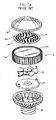
- FIG. 2 is an exploded perspective view illustrating a LED illumination lamp in accordance with the present invention
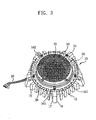
- FIG. 3 is a perspective view of the LED illumination lamp shown in FIG. 2 , with their components coupled together
- FIG. 4 is a front sectional view of the LED illumination lamp shown in FIG. 2
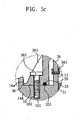
- FIGS. 5a , 5b and 5c are partially enlarged sectional views showing the structural relationship of a body, a LED module and a cover
- FIG. 6 is a bottom view depicting air circulation in the LED illumination lamp in accordance with the present invention.
- the body 10 is a body that can be placed or installed on or around a target illumination object.
- the body 10 may be produced by virtue of, e.g., die casting of aluminum which is lightweight and exhibits good performance of heat radiation.
- a so-called anode oxidation film is formed on the entire surface of the body 10 through an anodizing process to prevent oxidation of the body and improve durability thereof.
- the body 10 has at its center a bore 10a of predetermined diameter extending along a center axis X-X as best shown in FIG. 4 .
- An annular border part 11 protrudes in an upward direction generally in a flush relationship with the bore 10a.
- a fixture shoulder 12 Radially inwardly extending from the bore 10a is a fixture shoulder 12 that serves to support a printed circuit board of a LED module set forth below.
- a plurality of fixing lugs 123 protrudes radially inwardly toward the center axis X-X, each of the fixing lugs 123 having a thread hole 122 through which a bolt 121 is fastened to affix the printed circuit board of the LED module.
- a support shoulder 13 that holds and supports a heat radiation plate described below.
- the support shoulder 13 is spaced apart from the fixture shoulder 12 and protrudes radially inwardly toward the center axis X-X with a predetermined width.
- the support shoulder 13 has a cutout 131 through which an electric cable for supplying electric current to the printed circuit board extends with no interference with the support shoulder 13 or the body 10.
- the support shoulder 13 is also provided with through-holes 132 for allowing bolts 133 to pass therethrough in order to fasten the heat radiation plate in place.
- Five support ears 14 protrude radially outwardly from and are disposed along the periphery of the body 10 at an angular spacing of about 72 degrees.
- Formed on at least three of the support ears 14 are thread holes 142 through which bolts 141 are tightened to fasten the body 10, i.e., the lamp in an appropriate position for illumination.
- a plurality of radially outwardly protruding heat radiation fins 15 are disposed in between the support ears 14 so that they can dissipate the heat generated by the LEDs set forth below.
- the heat radiation fins 15 are spaced apart from one another substantially at an equal spacing (W), assuring that the ambient air can flow and circulate through between the respective heat radiation fins 15 to thereby cool down the body 10.
- W equal spacing
- the heat radiation fins 15 disposed between two neighboring support ears 14 are five in number in the present embodiment, the number of the heat radiation fins 15 may be greater or smaller as far as the rigidity of the body is kept intact.
- a planar seat part 16 is provided between the annular border part 11 and the top surfaces of the support ears 14 and the heat radiation fins 15 such that the below-noted cover can be stably placed on the seat part 16.
- the top surfaces of the support ears 14 and the heat radiation fins 15 are provided with step portions 14a and 15a which form the seat part 16.
- Formed on each of the step portions 14a of the support ears 14 is a thread hole 162 with which a bolt 161 is threadedly engaged to fasten the below-mentioned cover in place.
- a plurality of air vents 17 are formed at one side of each of the support ears 14 on the bottom side of the body 10 for allowing the ambient air to flow and circulate through the air vents 17 to thereby efficiently remove the heat generated by the LEDs.
- the air vents 17 are five in number and disposed at one side of each of the support ears 14 in the present embodiment, the number and position of the air vents 17 may be changed properly depending on the size of the body and the environment of use of the lamp.
- Designated by reference numeral 20 is a LED module for producing light for illumination.
- the LED module 20 is provided with a printed circuit board 21 of circular configuration which is inserted within the annular border part 11. Formed through the printed circuit board 21 are a number of through-holes 211, each of which is aligned with the corresponding thread hole 122 of the fixing lugs 123 on the fixture shoulder 12 of the body 10 so that the bolt 121 can be inserted therethrough. No electric circuit is formed around the through-holes 211 of the printed circuit board 21 to electrically isolate the board 21 from the bolt 121 and the body 10.
- a group of LEDs 22 is attached to the printed circuit board 21.
- the group of LEDs 22 consists of red LEDs, green LEDs and blue LEDs which are designed to produce decorative light of different colors.
- the group of LEDs 22 is preferably energized by electricity of less than 12W in order to save the electric energy and reduce the cost for illumination.
- a coat layer 23 of predetermined thickness is provided on the top surface of the printed circuit board 21 of the LED module 20 for the sake of waterproofing, insulation and light reflection.
- the coat layer 23 can be formed by way of fixedly securing the LED module 20 to the fixture shoulder 12 of the body 20 through the use of the bolt 121 and then applying coat material on the entire surface of the printed circuit board 21.
- white epoxy is used as the coat material for the coat layer 23 so that the light emitted from the group of LEDs can be reflected with an increased illuminance.
- an insulation film 24 is bonded to the rear surface of the printed circuit board 21 of the LED module 20 for insulating the printed circuit board 21 from the body 10, while blocking and absorbing external shocks to protect the LED module 20.
- the insulation film 24 is made of such insulating materials as polyamide, polyester, polyimide, glass epoxy and the like, which can provide effective insulation, increased light transmissivity and easy extrusion and injection.
- a heat radiation plate 25 of excellent heat conductivity is attached to the bottom surface of the printed circuit board 21 so that the heat generated from the group of LEDs 22 can be conducted to the outside through the heat radiation plate 25.
- the heat radiation plate 25 has insert holes 251 formed in alignment with the through-holes 132 of the support shoulder 13 and can be secured to the support shoulder 13 of the body 10 by tightening the bolt 132 through the insert holes 251 and the through-holes 132.
- an electric cable 26 Connected to printed circuit board 21 is an electric cable 26 through which electric current is supplied to the printed circuit board 21 and the group of LEDs 22.
- the electric cable 26 is also coupled to a controller (not shown) that serves to control the operation of the group of LEDs 22 in a predetermined manner.
- the electric cable 26 extends to the outside through the cutout 131 of the support shoulder 13 and one of the air vents 17 adjacent to the cutout 131 with no interference with the body 10.
- Designated by reference numeral 30 is a cover that functions to shield the top portion of the body 10 and the LED module 20 and has the capability of harmonizing the light emitted from the group of LEDs 22 to produce decorative light of different colors.
- the cover 30 may be made of, e.g., polycarbonate, which has increased durability and can prevent the cover 30 from damage by external shocks and positively protect the group of LEDs 22.
- the cover 30 is adapted to harmonize the lights of red (R), green (G) and blue (B) colors, which are emitted from the group of LEDs 22 under a given program, and produce decorative light of different color combination to provide desired illumination.
- the cover 30 is provided with a semitransparent color-producing part 31 that can prevent scattering of light to lessen the eye strain and prohibit the group of LEDs 22 and other components from exposure to the outside in an effort not to mar the aesthetic appearance and the feeling of texture of the cover 30. It would be preferred that the color-producing part 31 is formed through the use of a mold whose surface is treated by sanding, knurling or sandblasting.
- the color-producing part 31 of the cover 30 is provided on its bottom side with a vertically downwardly extending cylindrical protrusion 34 corresponding to the annular border part 11 of the body 10.
- the cylindrical protrusion 34 has a gasket 341 whose cross-section is of "U"-shape so that it can be firmly held in place by the cylindrical protrusion 34.
- the gasket 341 is kept in pressurized sealing contact with the border part 11 of the body 10 to provide the effect of gas-proofing, water-proofing and anti-vibration.
- the cover 30 is provided on its bottom periphery with an edge rim 38 that makes close contact with the seat part 16 of the body 10 and the step portions 14a, 15a of the support ears 14 and the heat radiation fins 15.
- a reception groove 35 is formed along a bottom end of the edge rim 38 of the cover 30 and an O-shaped seal ring 351 is fitted to the reception groove 35, the seal ring 351 making air-tight contact with the seat part 16 of the body 10.
- the cover 30 has a plurality of fastening parts 36 disposed along a periphery of the cover 30.
- Each of the fastening parts 36 cooperates with a bolt 161 to fasten the cover 30 to the body 10 and consists of a guide recess 361 for receiving and guiding the bolt 161 and a through-hole 362 adjoining to the guide recess 361 and in alignment with the thread hole 162 formed through the seat part 16 of the body 10 for allowing the bolt 161 to be inserted therethrough.
- An air passageway 37 is formed in the vicinity of the seat part 16 of the body 10 and remains in communication with interstices existing between the heat radiation fins 15 of the body 10.
- the air passageway 37 permits the ambient air to flow and circulate therethrough, thereby dissipating the heat generated from the LED module 20 and conducted to the border rim 11 of the body 10 and the bottom of the cover 30.
- Reference numeral 40 designates a protection layer that serves to shield and protect the interior of the body 10 and the bottom side of the illumination lamp.
- the protection layer 40 is formed for the purpose of waterproofing by molding, e.g., epoxy resin or silicon resin and has black color to avoid reflection of light. Needless to say, the protection layer 40 has such a thickness as not to close the air vents 17 of the body 10.
- the heat radiation plate 25 is placed on the support shoulder 13of the body 10 and secured by the bolt 133. Then, the LED module 20 inserted within the border rim 11 of the body 10 so that the printed circuit board 21 can be positioned on the fixture shoulder 12.
- the bolt 121 is inserted through the through-hole 211of the printed circuit board 21 and tightened into the thread hole 122 of the fixing lugs 123 of the fixture shoulder 12 to thereby fasten the LED module 20 to the body 10.
- a coat layer 23 of uniform thickness is formed on the top surface of the printed circuit board 21 by depositing white epoxy resin. This is to protect terminals of the respective LEDs 22 and provide the effect of enhanced waterproofing, insulation and light reflection.
- the cover 30 is placed on the seat part 16 of the body 10, after which the bolt 161 is inserted through the guide recess 361 and the through-hole 362 of each of the fastening parts 36 and tightened into the thread hole 162 of each of the support ears 14, thereby fastening the cover 30 to the body 10.
- the edge rim 38 formed on the bottom periphery of the cover 30 makes gap-free contact with the outer circumferential area of the seat part 16, the step portions 14a of the support ears 14 and the step portions 15a of the heat radiation fins 15.
- the gasket 341 held by the cylindrical protrusion 34 of the cover 30 is brought into air-tight contact with the border rim 11 of the body 10, whereas the seal ring 351 fitted into the reception groove 35 of the cover 30 is in close air-tight contact with the seat part 16 of the body 10. This helps maintain firm fitting and coupling state, while providing the effect of increased anti-vibration and water-proofing.
- the final step is to form the protection layer 40 on the bottom interior of the body 10 by molding epoxy resin or silicon resin.
- the thickness of the protection layer 40 should be limited to a size small enough not to close the air vents 17 of the body 10.
- the LED illumination lamp thus fabricated is installed at a proper position on or around the target illumination object. By turning on the LED illumination lamp, it becomes possible to illuminate the target object with decorative light of different color combination. Specifically, electric power and control signals are supplied to the LED module 20 from a controller not shown in the drawings, in response to which the LEDs 22 emit light of red (R), green (G) and blue (B) color, a part or all of which light is properly harmonized in the color-producing part 31 of the cover 30 and then directed to the outside, thus providing illumination of varying colors.
- R red
- G green
- B blue
- the light emitted from the respective LEDs 22 is reflected by the coat layer 23 of the printed circuit board 21, assuring that a greater amount of light can be directed to the target object whereby the target object can be illuminated with reduced electric power and increased illuminance.
- the heat can be effectively dissipated to the outside from the underneath of the cover 30 by the air circulating through the air passageway 37 in communication with the interstices between the heat radiation fins 15.
- the heat can be effectively dissipated by the air circulating through the air vents 17 formed at one side of each of the support ears 14.
- the gasket 341 held by the cylindrical protrusion 34 of the cover 30 is brought into closet contact with the border rim 11 of the body 10, the seal ring 351 fitted into the reception groove 35 of the cover 30 is in close air-tight contact with the seat part 16 of the body 10, and the edge rim 38 formed on the bottom periphery of the cover 30 makes gap-free contact with the outer circumferential area of the seat part 16, the step portions 14a of the support ears 14 and the step portions 15a of the heat radiation fins 15. This prevents unwanted loosening of the cover 30 and improves the effect of waterproofing and anti-vibration between the body 10 and the cover 30.
- the black protection layer 40 molded on the bottom interior of the body 10 can positively protect the components received in the body 10 and enhance the waterproofing of the illumination lamp.
- the illumination lamp can be installed at many different positions in varying fashions, thanks to the reduced overall height or thickness, and the electric power can be saved because no power cooling means is employed and the electricity is consumed by the LEDs alone.
- the semitransparent color-producing part 31 of the cover 30 is capable of harmonizing the light emitted from the LEDs 22 and producing decorative light of varying color combination. Even when the LEDs 22 are turned off, the LEDs 22 and other components are not exposed to the outside, thus improving aesthetic appearance of the illumination lamp.
- the body 10, the LED module 20 and the cover 30 are fitted and coupled together in an air-tight manner, the anti-vibration and waterproofing effect is greatly improved, resulting in prolonged life span of the illumination lamp.
- the present invention provides a variety of beneficial effects in that the LED illumination lamp can produce harmonized decorative light of different colors, can dissipate heat in a natural air circulation manner without having to use any separate power cooling means, and can fit a base, a LED module and a cover together in such a fashion as to assure improved hermetic seal, anti-vibration and waterproofing, thereby increasing reliability and prolonging life span of the illumination lamp.
Description
- The present invention is directed to a LED illumination lamp for irradiating decorative light on a variety of objects such as bridges, buildings and the like, and more specifically to a LED illumination lamp that has enhanced effect of light decoration, heat dissipation and electric energy saving, while assuring hermetic seal, anti-vibration and waterproofing between lamp components.
- As is generally known in the art, use has been made of varying kinds of illumination lamps for lightening or illuminating objects at night or indoors. Such illumination lamps are supplied with electric energy from a power source and convert the electric energy to light energy, thereby producing a beam of light for illumination. Typical examples of the illumination lamps include a glow lamp and a fluorescent lamp.
- Widely used in recent years is a Light Emitting Diode (LED) illumination lamp that has a benefit of providing illumination of different colors, although higher in price than the typical lamps referred to above. However, the LED illumination lamp poses a drawback in that it tends to be heated up and shows decreased efficiency when used for more than a predetermined time period. Use of the LED lamp for a prolonged period of time may result in excessive heat generation, thus shortening the life span of the lamp.
- A number of solutions have been proposed to the problem of excessive heat generation and life span reduction, one example of which is disclosed in
Korean Utility Model Registration No. 20-0336197 - A front lightening LED lamp taught in the '197 registration includes, as shown in
FIGS. 1a and1b , aheat radiation fin 1 having acylindrical partition wall 1b integrally formed with acenter part 1a, a cooling fan 2 received in thecylindrical partition wall 1b of theheat radiation fin 1 for forcibly circulating the air, acircuit board 3 for rectifying alternating current to direct current, asocket 5 attached to the end of theradiation fin 1 and electrically connected to a receptacle for a glow lamp, and a printedcircuit board 4 having a plurality ofLEDs 4a and mounted on the top of thecenter part 1a of theheat radiation fin 1. Each of theLEDs 4a is coated with atransparent cover 4b. Also provided is atransparent lens 6 that allows light to pass therethrough. - With the construction set forth above, the front lightening LED lamp of the '197 registration can exhibit increased illuminance with reduced energy consumption, provide proper intensity of illumination in compliance with the needs of a user by way of employing a structure that permits the user to directly affix LEDs to the front side of the lamp and thus confining the direction of light irradiation to a frontward direction, and attain cooling efficiency great enough to assure that the cooling fan can fully demonstrate its performance even when in continuous use, thereby extending the life span of the lamp.
- The front lightening LED lamp of the '197 registration, however, poses a problem in that it is difficult to illuminate an object with decorative light of different colors because a transparent lens or cover allows the light emitted from LEDs to transmit therethrough without any color variation. Another drawback is that the external appearance of the lamp is marred by the LEDs remaining completely exposed to the outside through the lens. A further shortcoming resides in that the lamp is complicated in structure and costly to manufacture because a separate cooling fan has to be employed to forcibly dissipate the heat generated by the LEDs. Moreover, use of the cooling fan may lead to increased consumption of electric energy and generate additional heat by itself, thus adversely affecting the surrounding components inclusive of LEDs.
- In addition to the disadvantages mentioned above, the front lightening LED lamp of the '197 registration has a further problem in that the connection or coupling between lamp components is too weak to provide an acceptable degree of hermetic seal, anti-vibration and waterproofing, which may result in reduced reliability and shortened life span of the lamp.
-
DE-U-20 2004 004 570 describes an LED illumination lamp according to the preamble ofclaim 1, having a body having a central bore with an internal support shoulder. The body furthermore comprises a plurality of heat radiation fins disposed around the circumference of the body at an equal spacing and a plurality of air vents formed between the heat radiation fins. A LED is mounted on a printed circuit board which is supported by the internal support shoulder. - Taking into account the above-noted and other problems inherent in the prior art lamps, it is an object of the present invention to provide a LED illumination lamp that can dissipate heat in a natural air circulation manner, allow LEDs to produce harmonized decorative light of different colors, make the external appearance of the lamp simple by prohibiting the LEDs from exposure to the outside through a cover, decrease consumption of electric energy, and enjoy compact overall configuration.
- Another object of the present invention is to provide a LED illumination lamp that has an improved effect of hermetic seal, anti-vibration and waterproofing between a base, a LED module and a cover, thereby assuring increased reliability and prolonged life span of the lamp.
- With these objects in view, the present invention provides a LED illumination lamp, comprising: a body adapted to be placed on or around an target illumination object, the body having a central bore with an internal fixture shoulder, a seat part provided around a top end of the central bore, a plurality of support ears formed along a periphery of the body at a predetermined spacing, a plurality of heat radiation fins disposed in between the support ears substantially at an equal spacing and a plurality of air vents formed at one side of each of the support ears for allowing air to flow and circulate through the air vents; a LED module having a printed circuit board affixed to the internal fixture shoulder of the body, a group of LEDs attached to the printed circuit board and consisting of red LEDs, green LEDs and blue LEDs, and an electric cable for supplying electric power to the LEDs and control signals to the printed circuit board; and a cover mounted on the seat part of the body, the cover having a semitransparent color-producing part capable of harmonizing colors of the light emitted from the LEDs and prohibiting the LED module from exposure to the outside and an air passageway in communication with interstices existing between the heat radiation fins of the body for permitting the heat generated from the LED module to dissipate to the outside.
- According to the LED illumination lamp of the present invention, the semitransparent color-producing part of the cover can harmonize the colors of the light emitted from the LEDs and illuminate a target object with decorative light of different colors. The heat can be dissipated in a natural air circulation manner without having to use any separate cooling means, thereby prolonging the life span of the lamp. The lamp is simple in construction and less costly to manufacture. The external appearance of the lamp becomes sleek and clean by prohibiting the LEDs from exposure to the outside through a cover. Removal of forced heat radiation means decreases consumption of electric energy. The base, the LED module and the cover are coupled together in such a manner as to assure hermetic seal, anti-vibration and waterproofing therebetween, thus increasing the reliability and prolonging the life span of the lamp.
- The above and other objects, features and advantages of the present invention will become apparent from the following description of a preferred embodiment given in conjunction with the accompanying drawings, in which:
-
FIGS. 1a and1b are exploded perspective view and cross-sectional view showing a prior art illumination lamp disclosed inKorean Utility Model Registration No. 20-0336197 -
FIG. 2 is an exploded perspective view illustrating a LED illumination lamp in accordance with the present invention; -
FIG. 3 is a perspective view of the LED illumination lamp shown inFIG. 2 , with their components coupled together; -
FIG. 4 is a front sectional view of the LED illumination lamp shown inFIG. 2 ; -
FIG. 5a is a partially enlarged sectional view of "a" part inFIG 4 ,FIG. 5b is a partially enlarged sectional view taken along line "b-b" inFIG. 2 , andFIG. 5c a partially enlarged sectional view of "c" part inFIG. 4 ; and -
FIG. 6 is a bottom view depicting air circulation in the LED illumination lamp in accordance with the present invention. - A preferred embodiment of a LED illumination lamp in accordance with the present invention will now be described in detail with reference to the drawings attached.
-
FIG. 2 is an exploded perspective view illustrating a LED illumination lamp in accordance with the present invention;FIG. 3 is a perspective view of the LED illumination lamp shown inFIG. 2 , with their components coupled together;FIG. 4 is a front sectional view of the LED illumination lamp shown inFIG. 2 ;FIGS. 5a ,5b and5c are partially enlarged sectional views showing the structural relationship of a body, a LED module and a cover; andFIG. 6 is a bottom view depicting air circulation in the LED illumination lamp in accordance with the present invention. - Referring to
FIGS. 2 through 6 , designated byreference numeral 10 is a body that can be placed or installed on or around a target illumination object. Thebody 10 may be produced by virtue of, e.g., die casting of aluminum which is lightweight and exhibits good performance of heat radiation. A so-called anode oxidation film is formed on the entire surface of thebody 10 through an anodizing process to prevent oxidation of the body and improve durability thereof. - The
body 10 has at its center abore 10a of predetermined diameter extending along a center axis X-X as best shown inFIG. 4 . Anannular border part 11 protrudes in an upward direction generally in a flush relationship with thebore 10a. Radially inwardly extending from thebore 10a is afixture shoulder 12 that serves to support a printed circuit board of a LED module set forth below. A plurality offixing lugs 123 protrudes radially inwardly toward the center axis X-X, each of thefixing lugs 123 having athread hole 122 through which abolt 121 is fastened to affix the printed circuit board of the LED module. - Formed below the
fixture shoulder 12 is asupport shoulder 13 that holds and supports a heat radiation plate described below. Thesupport shoulder 13 is spaced apart from thefixture shoulder 12 and protrudes radially inwardly toward the center axis X-X with a predetermined width. Particularly, thesupport shoulder 13 has acutout 131 through which an electric cable for supplying electric current to the printed circuit board extends with no interference with thesupport shoulder 13 or thebody 10. Thesupport shoulder 13 is also provided with through-holes 132 for allowingbolts 133 to pass therethrough in order to fasten the heat radiation plate in place. - Five
support ears 14 protrude radially outwardly from and are disposed along the periphery of thebody 10 at an angular spacing of about 72 degrees. Formed on at least three of thesupport ears 14 arethread holes 142 through whichbolts 141 are tightened to fasten thebody 10, i.e., the lamp in an appropriate position for illumination. - A plurality of radially outwardly protruding
heat radiation fins 15 are disposed in between thesupport ears 14 so that they can dissipate the heat generated by the LEDs set forth below. Theheat radiation fins 15 are spaced apart from one another substantially at an equal spacing (W), assuring that the ambient air can flow and circulate through between the respectiveheat radiation fins 15 to thereby cool down thebody 10. Although theheat radiation fins 15 disposed between two neighboringsupport ears 14 are five in number in the present embodiment, the number of theheat radiation fins 15 may be greater or smaller as far as the rigidity of the body is kept intact. - On the top surface of the
body 10, aplanar seat part 16 is provided between theannular border part 11 and the top surfaces of thesupport ears 14 and the heat radiation fins 15 such that the below-noted cover can be stably placed on theseat part 16. The top surfaces of thesupport ears 14 and theheat radiation fins 15 are provided withstep portions seat part 16. Formed on each of thestep portions 14a of thesupport ears 14 is athread hole 162 with which abolt 161 is threadedly engaged to fasten the below-mentioned cover in place. - A plurality of
air vents 17 are formed at one side of each of thesupport ears 14 on the bottom side of thebody 10 for allowing the ambient air to flow and circulate through theair vents 17 to thereby efficiently remove the heat generated by the LEDs. Although theair vents 17 are five in number and disposed at one side of each of thesupport ears 14 in the present embodiment, the number and position of theair vents 17 may be changed properly depending on the size of the body and the environment of use of the lamp. - Designated by
reference numeral 20 is a LED module for producing light for illumination. TheLED module 20 is provided with a printedcircuit board 21 of circular configuration which is inserted within theannular border part 11. Formed through the printedcircuit board 21 are a number of through-holes 211, each of which is aligned with thecorresponding thread hole 122 of the fixing lugs 123 on thefixture shoulder 12 of thebody 10 so that thebolt 121 can be inserted therethrough. No electric circuit is formed around the through-holes 211 of the printedcircuit board 21 to electrically isolate theboard 21 from thebolt 121 and thebody 10. - A group of
LEDs 22 is attached to the printedcircuit board 21. The group ofLEDs 22 consists of red LEDs, green LEDs and blue LEDs which are designed to produce decorative light of different colors. The group ofLEDs 22 is preferably energized by electricity of less than 12W in order to save the electric energy and reduce the cost for illumination. - A
coat layer 23 of predetermined thickness is provided on the top surface of the printedcircuit board 21 of theLED module 20 for the sake of waterproofing, insulation and light reflection. Thecoat layer 23 can be formed by way of fixedly securing theLED module 20 to thefixture shoulder 12 of thebody 20 through the use of thebolt 121 and then applying coat material on the entire surface of the printedcircuit board 21. Preferably, white epoxy is used as the coat material for thecoat layer 23 so that the light emitted from the group of LEDs can be reflected with an increased illuminance. - Moreover, an
insulation film 24 is bonded to the rear surface of the printedcircuit board 21 of theLED module 20 for insulating the printedcircuit board 21 from thebody 10, while blocking and absorbing external shocks to protect theLED module 20. Theinsulation film 24 is made of such insulating materials as polyamide, polyester, polyimide, glass epoxy and the like, which can provide effective insulation, increased light transmissivity and easy extrusion and injection. - A
heat radiation plate 25 of excellent heat conductivity is attached to the bottom surface of the printedcircuit board 21 so that the heat generated from the group ofLEDs 22 can be conducted to the outside through theheat radiation plate 25. Theheat radiation plate 25 has insert holes 251 formed in alignment with the through-holes 132 of thesupport shoulder 13 and can be secured to thesupport shoulder 13 of thebody 10 by tightening thebolt 132 through the insert holes 251 and the through-holes 132. - Connected to printed
circuit board 21 is anelectric cable 26 through which electric current is supplied to the printedcircuit board 21 and the group ofLEDs 22. Theelectric cable 26 is also coupled to a controller (not shown) that serves to control the operation of the group ofLEDs 22 in a predetermined manner. Theelectric cable 26 extends to the outside through thecutout 131 of thesupport shoulder 13 and one of the air vents 17 adjacent to thecutout 131 with no interference with thebody 10. - Designated by
reference numeral 30 is a cover that functions to shield the top portion of thebody 10 and theLED module 20 and has the capability of harmonizing the light emitted from the group ofLEDs 22 to produce decorative light of different colors. Thecover 30 may be made of, e.g., polycarbonate, which has increased durability and can prevent thecover 30 from damage by external shocks and positively protect the group ofLEDs 22. - In particular, the
cover 30 is adapted to harmonize the lights of red (R), green (G) and blue (B) colors, which are emitted from the group ofLEDs 22 under a given program, and produce decorative light of different color combination to provide desired illumination. Thecover 30 is provided with a semitransparent color-producingpart 31 that can prevent scattering of light to lessen the eye strain and prohibit the group ofLEDs 22 and other components from exposure to the outside in an effort not to mar the aesthetic appearance and the feeling of texture of thecover 30. It would be preferred that the color-producingpart 31 is formed through the use of a mold whose surface is treated by sanding, knurling or sandblasting. - The color-producing
part 31 of thecover 30 is provided on its bottom side with a vertically downwardly extendingcylindrical protrusion 34 corresponding to theannular border part 11 of thebody 10. Thecylindrical protrusion 34 has agasket 341 whose cross-section is of "U"-shape so that it can be firmly held in place by thecylindrical protrusion 34. Thegasket 341 is kept in pressurized sealing contact with theborder part 11 of thebody 10 to provide the effect of gas-proofing, water-proofing and anti-vibration. - The
cover 30 is provided on its bottom periphery with anedge rim 38 that makes close contact with theseat part 16 of thebody 10 and thestep portions support ears 14 and theheat radiation fins 15. Areception groove 35 is formed along a bottom end of the edge rim 38 of thecover 30 and an O-shapedseal ring 351 is fitted to thereception groove 35, theseal ring 351 making air-tight contact with theseat part 16 of thebody 10. - The
cover 30 has a plurality offastening parts 36 disposed along a periphery of thecover 30. Each of thefastening parts 36 cooperates with abolt 161 to fasten thecover 30 to thebody 10 and consists of aguide recess 361 for receiving and guiding thebolt 161 and a through-hole 362 adjoining to theguide recess 361 and in alignment with thethread hole 162 formed through theseat part 16 of thebody 10 for allowing thebolt 161 to be inserted therethrough. - An
air passageway 37 is formed in the vicinity of theseat part 16 of thebody 10 and remains in communication with interstices existing between theheat radiation fins 15 of thebody 10. Theair passageway 37 permits the ambient air to flow and circulate therethrough, thereby dissipating the heat generated from theLED module 20 and conducted to theborder rim 11 of thebody 10 and the bottom of thecover 30. -
Reference numeral 40 designates a protection layer that serves to shield and protect the interior of thebody 10 and the bottom side of the illumination lamp. Theprotection layer 40 is formed for the purpose of waterproofing by molding, e.g., epoxy resin or silicon resin and has black color to avoid reflection of light. Needless to say, theprotection layer 40 has such a thickness as not to close the air vents 17 of thebody 10. - Description will now shifted to fabrication and operation of the LED illumination lamp in accordance with present invention.
- The
heat radiation plate 25 is placed on the support shoulder 13of thebody 10 and secured by thebolt 133. Then, theLED module 20 inserted within theborder rim 11 of thebody 10 so that the printedcircuit board 21 can be positioned on thefixture shoulder 12. Thebolt 121 is inserted through the through-hole 211of the printedcircuit board 21 and tightened into thethread hole 122 of the fixing lugs 123 of thefixture shoulder 12 to thereby fasten theLED module 20 to thebody 10. - Under that state, a
coat layer 23 of uniform thickness is formed on the top surface of the printedcircuit board 21 by depositing white epoxy resin. This is to protect terminals of therespective LEDs 22 and provide the effect of enhanced waterproofing, insulation and light reflection. - Subsequently, the
cover 30 is placed on theseat part 16 of thebody 10, after which thebolt 161 is inserted through theguide recess 361 and the through-hole 362 of each of thefastening parts 36 and tightened into thethread hole 162 of each of thesupport ears 14, thereby fastening thecover 30 to thebody 10. In this state, the edge rim 38 formed on the bottom periphery of thecover 30 makes gap-free contact with the outer circumferential area of theseat part 16, thestep portions 14a of thesupport ears 14 and thestep portions 15a of theheat radiation fins 15. Thegasket 341 held by thecylindrical protrusion 34 of thecover 30 is brought into air-tight contact with theborder rim 11 of thebody 10, whereas theseal ring 351 fitted into thereception groove 35 of thecover 30 is in close air-tight contact with theseat part 16 of thebody 10. This helps maintain firm fitting and coupling state, while providing the effect of increased anti-vibration and water-proofing. - The final step is to form the
protection layer 40 on the bottom interior of thebody 10 by molding epoxy resin or silicon resin. The thickness of theprotection layer 40 should be limited to a size small enough not to close the air vents 17 of thebody 10. - The LED illumination lamp thus fabricated is installed at a proper position on or around the target illumination object. By turning on the LED illumination lamp, it becomes possible to illuminate the target object with decorative light of different color combination. Specifically, electric power and control signals are supplied to the
LED module 20 from a controller not shown in the drawings, in response to which theLEDs 22 emit light of red (R), green (G) and blue (B) color, a part or all of which light is properly harmonized in the color-producingpart 31 of thecover 30 and then directed to the outside, thus providing illumination of varying colors. - In addition, the light emitted from the
respective LEDs 22 is reflected by thecoat layer 23 of the printedcircuit board 21, assuring that a greater amount of light can be directed to the target object whereby the target object can be illuminated with reduced electric power and increased illuminance. - In the meantime, a part of the heat generated by the
LEDs 22 in the course of such illumination is dissipated to the outside through thecover 30, another part of the heat is dissipated through thebody 10 and theheat radiation fins 15 to the outside and a further part of the heat is dissipated through the printedcircuit board 21 and theheat radiation plate 25 to the outside. - Particularly, the heat can be effectively dissipated to the outside from the underneath of the
cover 30 by the air circulating through theair passageway 37 in communication with the interstices between theheat radiation fins 15. In addition to the dissipation in theheat radiation fins 15, the heat can be effectively dissipated by the air circulating through the air vents 17 formed at one side of each of thesupport ears 14. - Moreover, the
gasket 341 held by thecylindrical protrusion 34 of thecover 30 is brought into closet contact with theborder rim 11 of thebody 10, theseal ring 351 fitted into thereception groove 35 of thecover 30 is in close air-tight contact with theseat part 16 of thebody 10, and the edge rim 38 formed on the bottom periphery of thecover 30 makes gap-free contact with the outer circumferential area of theseat part 16, thestep portions 14a of thesupport ears 14 and thestep portions 15a of theheat radiation fins 15. This prevents unwanted loosening of thecover 30 and improves the effect of waterproofing and anti-vibration between thebody 10 and thecover 30. - The
black protection layer 40 molded on the bottom interior of thebody 10 can positively protect the components received in thebody 10 and enhance the waterproofing of the illumination lamp. - Furthermore, the illumination lamp can be installed at many different positions in varying fashions, thanks to the reduced overall height or thickness, and the electric power can be saved because no power cooling means is employed and the electricity is consumed by the LEDs alone.
- The semitransparent color-producing
part 31 of thecover 30 is capable of harmonizing the light emitted from theLEDs 22 and producing decorative light of varying color combination. Even when theLEDs 22 are turned off, theLEDs 22 and other components are not exposed to the outside, thus improving aesthetic appearance of the illumination lamp. - Particularly, since the
body 10, theLED module 20 and thecover 30 are fitted and coupled together in an air-tight manner, the anti-vibration and waterproofing effect is greatly improved, resulting in prolonged life span of the illumination lamp. - As described in the foregoing, the present invention provides a variety of beneficial effects in that the LED illumination lamp can produce harmonized decorative light of different colors, can dissipate heat in a natural air circulation manner without having to use any separate power cooling means, and can fit a base, a LED module and a cover together in such a fashion as to assure improved hermetic seal, anti-vibration and waterproofing, thereby increasing reliability and prolonging life span of the illumination lamp.
Claims (9)
- A LED illumination lamp, comprising:a body (10) adapted to be placed on or around an target illumination object, the body (10) having a central bore (10a) with an internal fixture shoulder (12), a seat part (16) provided around a top end of the central bore (10a), a plurality of support ears (14) formed along a periphery of the body (10) at a predetermined spacing, a plurality of heat radiation fins (15) disposed in between the support ears (14) substantially at an equal spacing and a plurality of air vents (17) formed at one side of each of the support ears (14) for allowing air to flow and circulate through the air vents (14); a cover (30) mounted on the seat part (16) of the body (10),a LED module (20) having a printed circuit board (21) affixed to the internal fixture shoulder (12) of the body (10), characterized by a group of LEDs (22) attached to the printed circuit board (22) and consisting of red LEDs, green LEDs and blue LEDs, and an electric cable (26) for supplying electric power to the LEDs (22) and control signals to the printed circuit board (21); andthe cover (30) having a semitransparent color-producing part (31) capable of harmonizing colors of the light emitted from the LEDs (22) and prohibiting the LED module (20) from exposure to the outside and an air passageway (32) in communication with interstices existing between the heat radiation fins (15) of the body (10) for permitting the heat generated from the LED module (20) to dissipate to the outside.
- The LED illumination lamp as recited in claim 1, wherein the cover (30) is provided with a plurality of fastening parts (36) disposed along a periphery of the cover (30), each of the fastening parts (36) consisting of a guide recess (361) for receiving and guiding a bolt (161) and a through-hole (362) adjoining to the guide recess (361) and in alignment with a thread hole (162) formed through the seat part (16) of the body (10) for allowing the bolt (161) to be inserted therethrough.
- The LED illumination lamp as recited in claim 1, wherein the support ears (14) are spaced apart at an angular spacing of 72 degrees, the cover (30) is made of polycarbonate resin, and the color-producing part (31) of the cover (30) is formed by a sandblasted mold.
- The LED illumination lamp as recited in claim 1, wherein a white epoxy layer (23) is coated on a top surface of the printed circuit board (21) of the LED module (20) for the sake of waterproofing, insulation and light reflection.
- The LED illumination lamp as recited in claim 1, wherein a heat radiation plate (25) is attached to a bottom surface of the printed circuit board (21) and secured to a support should (13) of the body (10) so that the heat generated from the LEDs (22) can be conducted to the outside through the heat radiation plate (25).
- The LED illumination lamp as recited in claim 1, wherein the color-producing part (31) of the cover (30) is provided on its bottom side with a cylindrical protrusion (34) corresponding to an annular border part (11) of the body (10), the cylindrical protrusion (34) having a gasket (341) kept in sealing contact with the border part (11) of the body (10), and the cover (30) is provided on its bottom periphery with an edge rim (38) making close contact with the seat part (16) of the body (10) and the top surfaces of the support ears (14) and the heat radiation fins (15).
- The LED illumination lamp as recited in claim 1, wherein an epoxy protection layer (40) of black color is provided on an inner bottom side of the body (10) for the purpose of waterproofing, light-shielding and concealment of components.
- The LED illumination lamp as recited in claim 1. wherein an insulation film (24) is bonded to a rear surface of the printed circuit board (21) of the LED module (20) for insulating the printed circuit board from the body and the heat radiation plate.
- The LED illumination lamp as recited in claim 6, wherein a reception groove (35) is formed along a bottom end of the edge rim of the cover (30) and an O-shaped seal ring (351) is fitted to the reception groove (35), the seal ring (351) making air-tight contact with the seat part (16) of the body (10).
Applications Claiming Priority (2)
| Application Number | Priority Date | Filing Date | Title |
|---|---|---|---|
| KR1020050023947A KR100496525B1 (en) | 2005-03-23 | 2005-03-23 | Led illumination lamp |
| KR1020050023948A KR100496522B1 (en) | 2005-03-23 | 2005-03-23 | Led illumination lamp |
Publications (3)
| Publication Number | Publication Date |
|---|---|
| EP1705421A2 EP1705421A2 (en) | 2006-09-27 |
| EP1705421A3 EP1705421A3 (en) | 2008-07-16 |
| EP1705421B1 true EP1705421B1 (en) | 2011-03-16 |
Family
ID=35734952
Family Applications (1)
| Application Number | Title | Priority Date | Filing Date |
|---|---|---|---|
| EP05025547A Not-in-force EP1705421B1 (en) | 2005-03-23 | 2005-11-23 | Led illumination lamp |
Country Status (3)
| Country | Link |
|---|---|
| US (1) | US7255460B2 (en) |
| EP (1) | EP1705421B1 (en) |
| DE (1) | DE602005026904D1 (en) |
Cited By (11)
| Publication number | Priority date | Publication date | Assignee | Title |
|---|---|---|---|---|
| US8294356B2 (en) | 2008-06-27 | 2012-10-23 | Toshiba Lighting & Technology Corporation | Light-emitting element lamp and lighting equipment |
| US8324789B2 (en) | 2009-09-25 | 2012-12-04 | Toshiba Lighting & Technology Corporation | Self-ballasted lamp and lighting equipment |
| US8354783B2 (en) | 2009-09-24 | 2013-01-15 | Toshiba Lighting & Technology Corporation | Light-emitting device.having a frame member surrounding light-emitting elements and illumination device utilizing light-emitting device |
| US8376562B2 (en) | 2009-09-25 | 2013-02-19 | Toshiba Lighting & Technology Corporation | Light-emitting module, self-ballasted lamp and lighting equipment |
| US8382325B2 (en) | 2009-06-30 | 2013-02-26 | Toshiba Lighting & Technology Corporation | Lamp and lighting equipment using the same |
| US8395304B2 (en) | 2009-09-25 | 2013-03-12 | Toshiba Lighting & Technology Corporation | Lamp and lighting equipment with thermally conductive substrate and body |
| US8398272B2 (en) | 2005-04-08 | 2013-03-19 | Toshiba Lighting & Technology Corporation | Lamp having outer shell to radiate heat of light source |
| US8415889B2 (en) | 2009-07-29 | 2013-04-09 | Toshiba Lighting & Technology Corporation | LED lighting equipment |
| US8500316B2 (en) | 2010-02-26 | 2013-08-06 | Toshiba Lighting & Technology Corporation | Self-ballasted lamp and lighting equipment |
| US8678618B2 (en) | 2009-09-25 | 2014-03-25 | Toshiba Lighting & Technology Corporation | Self-ballasted lamp having a light-transmissive member in contact with light emitting elements and lighting equipment incorporating the same |
| US8760042B2 (en) | 2009-02-27 | 2014-06-24 | Toshiba Lighting & Technology Corporation | Lighting device having a through-hole and a groove portion formed in the thermally conductive main body |
Families Citing this family (163)
| Publication number | Priority date | Publication date | Assignee | Title |
|---|---|---|---|---|
| DE202005007211U1 (en) * | 2005-05-06 | 2005-08-04 | Heine Optotechnik Gmbh & Co. Kg | lighting device |
| KR101144557B1 (en) * | 2006-03-27 | 2012-05-11 | 엘지이노텍 주식회사 | Lighting Device with Light Emitting Diodes and manufacture method thereof |
| US7784969B2 (en) * | 2006-04-12 | 2010-08-31 | Bhc Interim Funding Iii, L.P. | LED based light engine |
| US20070297177A1 (en) * | 2006-06-27 | 2007-12-27 | Bily Wang | Modular lamp structure |
| US7325949B1 (en) * | 2006-08-17 | 2008-02-05 | Augux Co., Ltd. | Quick assembling structure for LED lamp and heat dissipating module |
| US7527397B2 (en) * | 2006-09-26 | 2009-05-05 | Chia-Mao Li | Solid state lighting package structure |
| US20080080184A1 (en) * | 2006-10-03 | 2008-04-03 | Cao Group Inc. | Pixilated LED Light Source for Channel Letter Illumination |
| EP1914470B1 (en) * | 2006-10-20 | 2016-05-18 | OSRAM GmbH | Semiconductor lamp |
| EP2080950A4 (en) * | 2006-11-10 | 2010-12-22 | Thermoking Technology Internat | A heat dissipating apparatus for lamp and method thereof |
| TWM310984U (en) * | 2006-11-28 | 2007-05-01 | Primo Lite Co Ltd | Lamp structure of light emitting diode |
| US20080175003A1 (en) * | 2007-01-22 | 2008-07-24 | Cheng Home Electronics Co., Ltd. | Led sunken lamp |
| JP5542658B2 (en) * | 2007-05-04 | 2014-07-09 | コーニンクレッカ フィリップス エヌ ヴェ | LED-type luminaire and related method for temperature management |
| ES2531377T3 (en) * | 2007-06-07 | 2015-03-13 | Zhejiang Mingchuang Opto Electronic Technology Co Ltd | High power LED lamp |
| US7686486B2 (en) * | 2007-06-30 | 2010-03-30 | Osram Sylvania Inc. | LED lamp module |
| US7874699B2 (en) * | 2007-07-05 | 2011-01-25 | Aeon Lighting Technology Inc. | Heat dissipating device for LED light-emitting module |
| WO2009017709A1 (en) * | 2007-08-01 | 2009-02-05 | Charles Bolta | Compact fluorescent lamp |
| CN101368719B (en) * | 2007-08-13 | 2011-07-06 | 太一节能系统股份有限公司 | LED lamp |
| DE102007049480A1 (en) * | 2007-10-11 | 2009-04-23 | Avertronics Inc. | Lamp device for illuminating e.g. stage, has circuit deciding, corresponding to adjustment of module switch, whether data packet signal is processed, where circuit decodes data packet signal and controls illuminant if signal is processed |
| JP4569683B2 (en) | 2007-10-16 | 2010-10-27 | 東芝ライテック株式会社 | Light emitting element lamp and lighting apparatus |
| TWM334272U (en) * | 2007-12-04 | 2008-06-11 | Cooler Master Co Ltd | An LED lighting device |
| JP2011505702A (en) * | 2007-12-07 | 2011-02-24 | オスラム ゲゼルシャフト ミット ベシュレンクテル ハフツング | Heat sink and lighting device including heat sink |
| TWM332794U (en) | 2007-12-17 | 2008-05-21 | shi-quan Tang | Structure improvement on heat radiating seat assembly of LED |
| US8118447B2 (en) | 2007-12-20 | 2012-02-21 | Altair Engineering, Inc. | LED lighting apparatus with swivel connection |
| US7712918B2 (en) | 2007-12-21 | 2010-05-11 | Altair Engineering , Inc. | Light distribution using a light emitting diode assembly |
| KR100908136B1 (en) * | 2007-12-27 | 2009-07-16 | 홍삼표 | Led lamp |
| JP5353216B2 (en) * | 2008-01-07 | 2013-11-27 | 東芝ライテック株式会社 | LED bulb and lighting fixture |
| US7985004B1 (en) | 2008-04-30 | 2011-07-26 | Genlyte Thomas Group Llc | Luminaire |
| US7972036B1 (en) | 2008-04-30 | 2011-07-05 | Genlyte Thomas Group Llc | Modular bollard luminaire louver |
| TWI340219B (en) * | 2008-05-09 | 2011-04-11 | Neobulb Technologies Inc | Outdoor illuminating apparatus |
| CN101576205B (en) * | 2008-05-09 | 2011-01-12 | 范金晶 | LED bulb for replacing reflecting cup-shaped halogen bulb |
| JP5320560B2 (en) * | 2008-05-20 | 2013-10-23 | 東芝ライテック株式会社 | Light source unit and lighting device |
| US8360599B2 (en) | 2008-05-23 | 2013-01-29 | Ilumisys, Inc. | Electric shock resistant L.E.D. based light |
| US7976196B2 (en) | 2008-07-09 | 2011-07-12 | Altair Engineering, Inc. | Method of forming LED-based light and resulting LED-based light |
| TWM346745U (en) * | 2008-07-25 | 2008-12-11 | Forcecon Technology Co Ltd | LED Lamp with heat-dissipation toward the terminal direction |
| US8427059B2 (en) * | 2008-07-31 | 2013-04-23 | Toshiba Lighting & Technology Corporation | Lighting device |
| US7946729B2 (en) | 2008-07-31 | 2011-05-24 | Altair Engineering, Inc. | Fluorescent tube replacement having longitudinally oriented LEDs |
| US7934851B1 (en) | 2008-08-19 | 2011-05-03 | Koninklijke Philips Electronics N.V. | Vertical luminaire |
| WO2010022636A1 (en) * | 2008-08-25 | 2010-03-04 | 广州南科集成电子有限公司 | Radiating device for lamp and led lamp |
| US8674626B2 (en) | 2008-09-02 | 2014-03-18 | Ilumisys, Inc. | LED lamp failure alerting system |
| TWI395906B (en) * | 2008-09-05 | 2013-05-11 | Foxconn Tech Co Ltd | Led lamp |
| US8256924B2 (en) | 2008-09-15 | 2012-09-04 | Ilumisys, Inc. | LED-based light having rapidly oscillating LEDs |
| US7902761B2 (en) * | 2008-10-03 | 2011-03-08 | Next Gen Illumination, Inc | Dimmable LED lamp |
| US7938562B2 (en) | 2008-10-24 | 2011-05-10 | Altair Engineering, Inc. | Lighting including integral communication apparatus |
| US8901823B2 (en) | 2008-10-24 | 2014-12-02 | Ilumisys, Inc. | Light and light sensor |
| US8653984B2 (en) | 2008-10-24 | 2014-02-18 | Ilumisys, Inc. | Integration of LED lighting control with emergency notification systems |
| US8444292B2 (en) | 2008-10-24 | 2013-05-21 | Ilumisys, Inc. | End cap substitute for LED-based tube replacement light |
| US8324817B2 (en) | 2008-10-24 | 2012-12-04 | Ilumisys, Inc. | Light and light sensor |
| US8214084B2 (en) | 2008-10-24 | 2012-07-03 | Ilumisys, Inc. | Integration of LED lighting with building controls |
| US8240885B2 (en) * | 2008-11-18 | 2012-08-14 | Abl Ip Holding Llc | Thermal management of LED lighting systems |
| US8092044B1 (en) | 2008-11-21 | 2012-01-10 | Tomar Electronics, Inc. | LED light assembly and related methods |
| US8070328B1 (en) | 2009-01-13 | 2011-12-06 | Koninkliljke Philips Electronics N.V. | LED downlight |
| US8556452B2 (en) | 2009-01-15 | 2013-10-15 | Ilumisys, Inc. | LED lens |
| US8362710B2 (en) | 2009-01-21 | 2013-01-29 | Ilumisys, Inc. | Direct AC-to-DC converter for passive component minimization and universal operation of LED arrays |
| US8664880B2 (en) | 2009-01-21 | 2014-03-04 | Ilumisys, Inc. | Ballast/line detection circuit for fluorescent replacement lamps |
| FR2944853B1 (en) * | 2009-04-27 | 2012-10-12 | Hmi Innovation | LED LIGHTING DEVICE INCORPORATING A SUPPORT FOR THERMAL DISSIPATION. |
| USD654192S1 (en) | 2009-05-13 | 2012-02-14 | Lighting Science Group Coporation | Body portion of a lamp |
| US8330381B2 (en) | 2009-05-14 | 2012-12-11 | Ilumisys, Inc. | Electronic circuit for DC conversion of fluorescent lighting ballast |
| US8197091B1 (en) | 2009-05-15 | 2012-06-12 | Koninklijke Philips Electronics N.V. | LED unit for installation in a post-top luminaire |
| US8123378B1 (en) | 2009-05-15 | 2012-02-28 | Koninklijke Philips Electronics N.V. | Heatsink for cooling at least one LED |
| KR101007134B1 (en) | 2009-06-05 | 2011-01-10 | 엘지이노텍 주식회사 | Lighting Device |
| JP4957927B2 (en) * | 2009-05-29 | 2012-06-20 | 東芝ライテック株式会社 | Light bulb shaped lamp and lighting equipment |
| US8299695B2 (en) | 2009-06-02 | 2012-10-30 | Ilumisys, Inc. | Screw-in LED bulb comprising a base having outwardly projecting nodes |
| WO2011005579A2 (en) | 2009-06-23 | 2011-01-13 | Altair Engineering, Inc. | Illumination device including leds and a switching power control system |
| JP5711730B2 (en) | 2009-06-25 | 2015-05-07 | コーニンクレッカ フィリップス エヌ ヴェ | Thermal management device |
| JP5354191B2 (en) * | 2009-06-30 | 2013-11-27 | 東芝ライテック株式会社 | Light bulb shaped lamp and lighting equipment |
| USD652564S1 (en) * | 2009-07-23 | 2012-01-17 | Lighting Science Group Corporation | Luminaire |
| US10352550B1 (en) * | 2009-07-29 | 2019-07-16 | Deepsea Power & Light Llc | Submersible LED light fixture with multilayer stack for pressure transfer |
| CN101994935A (en) * | 2009-08-18 | 2011-03-30 | 富准精密工业(深圳)有限公司 | Light emitting diode lamp |
| JP5601512B2 (en) | 2009-09-14 | 2014-10-08 | 東芝ライテック株式会社 | Light emitting device and lighting device |
| TWM402992U (en) | 2009-09-24 | 2011-05-01 | Molex Inc | Light module |
| CN102686938B (en) * | 2009-10-12 | 2014-11-26 | 莫列斯公司 | Light module |
| US9028097B2 (en) | 2009-10-30 | 2015-05-12 | Cree, Inc. | LED apparatus and method for accurate lens alignment |
| US9404634B2 (en) * | 2009-10-30 | 2016-08-02 | Cree, Inc. | LED light fixture with facilitated lensing alignment and method of manufacture |
| JP2013513200A (en) * | 2009-12-04 | 2013-04-18 | オスラム ゲーエムベーハー | LED light emitting module having light sensor molded together |
| DE102009047489B4 (en) * | 2009-12-04 | 2013-07-11 | Osram Gmbh | light module |
| US8506127B2 (en) | 2009-12-11 | 2013-08-13 | Koninklijke Philips N.V. | Lens frame with a LED support surface and heat dissipating structure |
| CN102128367A (en) * | 2010-01-13 | 2011-07-20 | 富准精密工业(深圳)有限公司 | Light-emitting diode lamp |
| CA2792940A1 (en) | 2010-03-26 | 2011-09-19 | Ilumisys, Inc. | Led light with thermoelectric generator |
| WO2011119907A2 (en) | 2010-03-26 | 2011-09-29 | Altair Engineering, Inc. | Led light tube with dual sided light distribution |
| WO2011119958A1 (en) | 2010-03-26 | 2011-09-29 | Altair Engineering, Inc. | Inside-out led bulb |
| GB2479423A (en) * | 2010-04-09 | 2011-10-12 | Lemnis Lighting Patent Holding B V | LED lamp with heat removal body |
| US20110267834A1 (en) * | 2010-04-28 | 2011-11-03 | Hayward Industries, Inc. | Underwater Light Having A Sealed Polymer Housing and Method of Manufacture Therefor |
| USD663446S1 (en) | 2010-05-04 | 2012-07-10 | Lighting Science Group Corporation | Body portion of a bulb |
| USD658791S1 (en) | 2010-05-04 | 2012-05-01 | Lighting Science Group Corporation | Luminaire |
| USD659266S1 (en) | 2010-05-04 | 2012-05-08 | Lighting Science Group Corporation | Luminaire |
| US8414147B2 (en) * | 2010-05-24 | 2013-04-09 | John E. Thrailkill | Solid state lighting device |
| US8926123B2 (en) | 2010-05-24 | 2015-01-06 | John E. Thrailkill | Solid state lighting device |
| CN102449382B (en) * | 2010-06-02 | 2015-06-03 | 松下电器产业株式会社 | Lamp and lighting device |
| WO2011156886A1 (en) * | 2010-06-18 | 2011-12-22 | Vialuminary Ltd. | Led street light |
| US8454193B2 (en) | 2010-07-08 | 2013-06-04 | Ilumisys, Inc. | Independent modules for LED fluorescent light tube replacement |
| JP2013531350A (en) | 2010-07-12 | 2013-08-01 | イルミシス,インコーポレイテッド | Circuit board mount for LED arc tube |
| US8523394B2 (en) | 2010-10-29 | 2013-09-03 | Ilumisys, Inc. | Mechanisms for reducing risk of shock during installation of light tube |
| US9091399B2 (en) * | 2010-11-11 | 2015-07-28 | Bridgelux, Inc. | Driver-free light-emitting device |
| US8870415B2 (en) | 2010-12-09 | 2014-10-28 | Ilumisys, Inc. | LED fluorescent tube replacement light with reduced shock hazard |
| WO2012097721A1 (en) * | 2011-01-21 | 2012-07-26 | 贵州光浦森光电有限公司 | Method and device for constructing high-power led lighting fixture |
| US20120217870A1 (en) * | 2011-02-24 | 2012-08-30 | Soni Vimal J | LED Light Assembly |
| USD657087S1 (en) | 2011-05-13 | 2012-04-03 | Lsi Industries, Inc. | Lighting |
| US8585238B2 (en) | 2011-05-13 | 2013-11-19 | Lsi Industries, Inc. | Dual zone lighting apparatus |
| JP5720468B2 (en) * | 2011-07-26 | 2015-05-20 | 東芝ライテック株式会社 | Light bulb shaped LED lamp |
| US9072171B2 (en) | 2011-08-24 | 2015-06-30 | Ilumisys, Inc. | Circuit board mount for LED light |
| KR101095868B1 (en) * | 2011-09-08 | 2011-12-21 | 이슬기 | Led module for lighting |
| TWM432938U (en) * | 2011-10-26 | 2012-07-01 | Enlight Corp | M1010701_3919 |
| TW201331503A (en) * | 2012-01-20 | 2013-08-01 | Taiwan Fu Hsing Ind Co Ltd | Lighting structure and a fixing base thereof |
| USD666750S1 (en) | 2012-02-13 | 2012-09-04 | Lighting Science Group Corporation | Luminaire |
| WO2013131002A1 (en) | 2012-03-02 | 2013-09-06 | Ilumisys, Inc. | Electrical connector header for an led-based light |
| US9188322B2 (en) * | 2012-03-26 | 2015-11-17 | Asia Vital Components Co., Ltd. | Heat dissipation structure for LED lighting |
| WO2014008463A1 (en) | 2012-07-06 | 2014-01-09 | Ilumisys, Inc. | Power supply assembly for led-based light tube |
| US8994273B2 (en) | 2012-07-09 | 2015-03-31 | Mp Design Inc. | Light-emitting diode fixture with an improved thermal control system |
| US9271367B2 (en) | 2012-07-09 | 2016-02-23 | Ilumisys, Inc. | System and method for controlling operation of an LED-based light |
| US8786193B2 (en) * | 2012-09-12 | 2014-07-22 | Elementech International Co., Ltd. | LED lamp |
| JP6136196B2 (en) * | 2012-10-31 | 2017-05-31 | 岩崎電気株式会社 | lamp |
| US20140198501A1 (en) * | 2013-01-17 | 2014-07-17 | Yao-Huang Lin | Lighting base of the led lamp and its stamping mold |
| JP6108304B2 (en) * | 2013-03-12 | 2017-04-05 | パナソニックIpマネジメント株式会社 | Illumination light source and illumination device |
| US9285084B2 (en) | 2013-03-14 | 2016-03-15 | Ilumisys, Inc. | Diffusers for LED-based lights |
| US20140268791A1 (en) * | 2013-03-15 | 2014-09-18 | Cree, Inc. | Lighting fixtures for solid-state light sources |
| US10551044B2 (en) | 2015-11-16 | 2020-02-04 | DMF, Inc. | Recessed lighting assembly |
| US11435064B1 (en) | 2013-07-05 | 2022-09-06 | DMF, Inc. | Integrated lighting module |
| US10591120B2 (en) | 2015-05-29 | 2020-03-17 | DMF, Inc. | Lighting module for recessed lighting systems |
| US10139059B2 (en) | 2014-02-18 | 2018-11-27 | DMF, Inc. | Adjustable compact recessed lighting assembly with hangar bars |
| US10753558B2 (en) | 2013-07-05 | 2020-08-25 | DMF, Inc. | Lighting apparatus and methods |
| US10563850B2 (en) | 2015-04-22 | 2020-02-18 | DMF, Inc. | Outer casing for a recessed lighting fixture |
| US9964266B2 (en) | 2013-07-05 | 2018-05-08 | DMF, Inc. | Unified driver and light source assembly for recessed lighting |
| US11060705B1 (en) | 2013-07-05 | 2021-07-13 | DMF, Inc. | Compact lighting apparatus with AC to DC converter and integrated electrical connector |
| US11255497B2 (en) | 2013-07-05 | 2022-02-22 | DMF, Inc. | Adjustable electrical apparatus with hangar bars for installation in a building |
| US9736895B1 (en) * | 2013-10-03 | 2017-08-15 | Ketra, Inc. | Color mixing optics for LED illumination device |
| US9267650B2 (en) | 2013-10-09 | 2016-02-23 | Ilumisys, Inc. | Lens for an LED-based light |
| US9651224B1 (en) * | 2014-01-17 | 2017-05-16 | Paul Burgess | Work light with variable voltage transformer and removable lens |
| KR20160111975A (en) | 2014-01-22 | 2016-09-27 | 일루미시스, 인크. | Led-based light with addressed leds |
| USD737497S1 (en) | 2014-02-24 | 2015-08-25 | Paul Burgess | Quick change lens gasket |
| NL1040746B1 (en) | 2014-03-28 | 2016-01-18 | Rubitech Luctron B V | LED lighting fixture and the method for manufacturing it. |
| US9439299B2 (en) * | 2014-03-29 | 2016-09-06 | Bridgelux, Inc. | Low-profile outdoor lighting module with light emitting diodes |
| US9510400B2 (en) | 2014-05-13 | 2016-11-29 | Ilumisys, Inc. | User input systems for an LED-based light |
| JP6781553B2 (en) * | 2015-03-25 | 2020-11-04 | エルジー イノテック カンパニー リミテッド | Holder and lighting device equipped with it |
| CN107636388A (en) * | 2015-05-01 | 2018-01-26 | 豪倍公司 | High directivity optical illumination utensil |
| USD771296S1 (en) | 2015-05-01 | 2016-11-08 | Hubbell Incorporated | Outdoor luminaire |
| US10161568B2 (en) | 2015-06-01 | 2018-12-25 | Ilumisys, Inc. | LED-based light with canted outer walls |
| US9869464B2 (en) | 2015-09-23 | 2018-01-16 | Cooper Technologies Company | Hermetically-sealed light fixture for hazardous environments |
| USD851046S1 (en) | 2015-10-05 | 2019-06-11 | DMF, Inc. | Electrical Junction Box |
| CN206507321U (en) * | 2016-11-28 | 2017-09-22 | 深圳市艾维普思科技股份有限公司 | The fixed structure and electronic cigarette of the PCBA control panels of electronic cigarette |
| USD827915S1 (en) * | 2016-12-29 | 2018-09-04 | Gregg Wilson | LED stacker bulb lock |
| US20180202637A1 (en) * | 2017-01-17 | 2018-07-19 | Abl Ip Holding Llc | Mounting system for light fixture |
| USD832487S1 (en) | 2017-01-17 | 2018-10-30 | Abl Ip Holding Llc | Light fixture |
| US10488000B2 (en) | 2017-06-22 | 2019-11-26 | DMF, Inc. | Thin profile surface mount lighting apparatus |
| WO2018237294A2 (en) | 2017-06-22 | 2018-12-27 | DMF, Inc. | Thin profile surface mount lighting apparatus |
| USD905327S1 (en) | 2018-05-17 | 2020-12-15 | DMF, Inc. | Light fixture |
| US11067231B2 (en) | 2017-08-28 | 2021-07-20 | DMF, Inc. | Alternate junction box and arrangement for lighting apparatus |
| CN111670322B (en) | 2017-11-28 | 2022-04-26 | Dmf股份有限公司 | Adjustable hanger rod assembly |
| CA3087187A1 (en) | 2017-12-27 | 2019-07-04 | DMF, Inc. | Methods and apparatus for adjusting a luminaire |
| USD857979S1 (en) | 2018-03-05 | 2019-08-27 | Intellytech Llc | Foldable light emitting mat |
| USD857980S1 (en) | 2018-04-05 | 2019-08-27 | Intellytech Llc | Foldable light emitting mat |
| USD877957S1 (en) | 2018-05-24 | 2020-03-10 | DMF Inc. | Light fixture |
| WO2019241198A1 (en) | 2018-06-11 | 2019-12-19 | DMF, Inc. | A polymer housing for a recessed lighting system and methods for using same |
| USD903605S1 (en) | 2018-06-12 | 2020-12-01 | DMF, Inc. | Plastic deep electrical junction box |
| WO2020072592A1 (en) | 2018-10-02 | 2020-04-09 | Ver Lighting Llc | A bar hanger assembly with mating telescoping bars |
| USD864877S1 (en) | 2019-01-29 | 2019-10-29 | DMF, Inc. | Plastic deep electrical junction box with a lighting module mounting yoke |
| USD901398S1 (en) | 2019-01-29 | 2020-11-10 | DMF, Inc. | Plastic deep electrical junction box |
| USD1012864S1 (en) | 2019-01-29 | 2024-01-30 | DMF, Inc. | Portion of a plastic deep electrical junction box |
| US11168876B2 (en) | 2019-03-06 | 2021-11-09 | Hayward Industries, Inc. | Underwater light having programmable controller and replaceable light-emitting diode (LED) assembly |
| USD966877S1 (en) | 2019-03-14 | 2022-10-18 | Ver Lighting Llc | Hanger bar for a hanger bar assembly |
| WO2021051101A1 (en) | 2019-09-12 | 2021-03-18 | DMF, Inc. | Miniature lighting module and lighting fixtures using same |
| CA3124976A1 (en) | 2020-07-17 | 2022-01-17 | DMF, Inc. | Polymer housing for a lighting system and methods for using same |
| USD990030S1 (en) | 2020-07-17 | 2023-06-20 | DMF, Inc. | Housing for a lighting system |
| CA3125954A1 (en) | 2020-07-23 | 2022-01-23 | DMF, Inc. | Lighting module having field-replaceable optics, improved cooling, and tool-less mounting features |
Family Cites Families (15)
| Publication number | Priority date | Publication date | Assignee | Title |
|---|---|---|---|---|
| US4729076A (en) * | 1984-11-15 | 1988-03-01 | Tsuzawa Masami | Signal light unit having heat dissipating function |
| US4733335A (en) * | 1984-12-28 | 1988-03-22 | Koito Manufacturing Co., Ltd. | Vehicular lamp |
| US6793374B2 (en) * | 1998-09-17 | 2004-09-21 | Simon H. A. Begemann | LED lamp |
| JP2002532893A (en) * | 1998-12-17 | 2002-10-02 | コーニンクレッカ フィリップス エレクトロニクス エヌ ヴィ | Light engine |
| DE20007235U1 (en) * | 1999-05-19 | 2000-07-27 | Agon Tech Corp | General purpose lamp |
| US6786625B2 (en) * | 1999-05-24 | 2004-09-07 | Jam Strait, Inc. | LED light module for vehicles |
| US6161910A (en) * | 1999-12-14 | 2000-12-19 | Aerospace Lighting Corporation | LED reading light |
| US6598996B1 (en) * | 2001-04-27 | 2003-07-29 | Pervaiz Lodhie | LED light bulb |
| US6685339B2 (en) * | 2002-02-14 | 2004-02-03 | Polaris Pool Systems, Inc. | Sparkle light bulb with controllable memory function |
| DE10216085A1 (en) * | 2002-04-11 | 2003-11-06 | Sill Franz Gmbh | Color changing spotlights |
| US6964501B2 (en) * | 2002-12-24 | 2005-11-15 | Altman Stage Lighting Co., Ltd. | Peltier-cooled LED lighting assembly |
| US7021807B2 (en) * | 2003-02-25 | 2006-04-04 | Tong Fatt Chew | Signal lamp incorporating spatially separated clustered light emitting devices |
| ITTO20030165A1 (en) * | 2003-03-06 | 2004-09-07 | Space Cannon Vh S P A | LED LIGHT PROJECTOR |
| KR200336197Y1 (en) | 2003-10-02 | 2003-12-12 | 주식회사 대진디엠피 | Front irradiating Light using by LED |
| DE202004004570U1 (en) * | 2004-03-10 | 2004-05-27 | Conrad Electronic Gmbh | Light source for lamp for replacing e.g. halogen lamps etc. with housing containing at least one light emitting diode (LED), which is fitted on cooling member for waste heat connection, coupled to housing |
-
2005
- 2005-11-07 US US11/269,307 patent/US7255460B2/en not_active Expired - Fee Related
- 2005-11-23 EP EP05025547A patent/EP1705421B1/en not_active Not-in-force
- 2005-11-23 DE DE602005026904T patent/DE602005026904D1/en active Active
Cited By (14)
| Publication number | Priority date | Publication date | Assignee | Title |
|---|---|---|---|---|
| US9080759B2 (en) | 2005-04-08 | 2015-07-14 | Toshiba Lighting & Technology Corporation | Lamp having outer shell to radiate heat of light source |
| US8858041B2 (en) | 2005-04-08 | 2014-10-14 | Toshiba Lighting & Technology Corporation | Lamp having outer shell to radiate heat of light source |
| US8398272B2 (en) | 2005-04-08 | 2013-03-19 | Toshiba Lighting & Technology Corporation | Lamp having outer shell to radiate heat of light source |
| US8294356B2 (en) | 2008-06-27 | 2012-10-23 | Toshiba Lighting & Technology Corporation | Light-emitting element lamp and lighting equipment |
| US8760042B2 (en) | 2009-02-27 | 2014-06-24 | Toshiba Lighting & Technology Corporation | Lighting device having a through-hole and a groove portion formed in the thermally conductive main body |
| US8382325B2 (en) | 2009-06-30 | 2013-02-26 | Toshiba Lighting & Technology Corporation | Lamp and lighting equipment using the same |
| US8415889B2 (en) | 2009-07-29 | 2013-04-09 | Toshiba Lighting & Technology Corporation | LED lighting equipment |
| US8354783B2 (en) | 2009-09-24 | 2013-01-15 | Toshiba Lighting & Technology Corporation | Light-emitting device.having a frame member surrounding light-emitting elements and illumination device utilizing light-emitting device |
| US8376562B2 (en) | 2009-09-25 | 2013-02-19 | Toshiba Lighting & Technology Corporation | Light-emitting module, self-ballasted lamp and lighting equipment |
| US8678618B2 (en) | 2009-09-25 | 2014-03-25 | Toshiba Lighting & Technology Corporation | Self-ballasted lamp having a light-transmissive member in contact with light emitting elements and lighting equipment incorporating the same |
| US8395304B2 (en) | 2009-09-25 | 2013-03-12 | Toshiba Lighting & Technology Corporation | Lamp and lighting equipment with thermally conductive substrate and body |
| US8998457B2 (en) | 2009-09-25 | 2015-04-07 | Toshiba Lighting & Technology Corporation | Self-ballasted lamp and lighting equipment having a support portion in contact with an inner circumference of a base body |
| US8324789B2 (en) | 2009-09-25 | 2012-12-04 | Toshiba Lighting & Technology Corporation | Self-ballasted lamp and lighting equipment |
| US8500316B2 (en) | 2010-02-26 | 2013-08-06 | Toshiba Lighting & Technology Corporation | Self-ballasted lamp and lighting equipment |
Also Published As
| Publication number | Publication date |
|---|---|
| US20060215408A1 (en) | 2006-09-28 |
| EP1705421A3 (en) | 2008-07-16 |
| DE602005026904D1 (en) | 2011-04-28 |
| US7255460B2 (en) | 2007-08-14 |
| EP1705421A2 (en) | 2006-09-27 |
Similar Documents
| Publication | Publication Date | Title |
|---|---|---|
| EP1705421B1 (en) | Led illumination lamp | |
| KR100496522B1 (en) | Led illumination lamp | |
| JP5716973B2 (en) | lighting equipment | |
| US8727572B2 (en) | Illuminating apparatus | |
| KR101079269B1 (en) | Round down light using LED | |
| EP2752617B1 (en) | Spherical lamp with easy heat dissipation | |
| KR100496525B1 (en) | Led illumination lamp | |
| JP5739770B2 (en) | LED lighting device | |
| US20110084586A1 (en) | LED recessed light with heat sink | |
| JP5726680B2 (en) | LED lighting device | |
| JP2007134067A (en) | Indoor illumination lamp | |
| JP2010129501A (en) | Illumination device and luminaire | |
| JP2012181969A (en) | Bulb type light-emitting element lamp, and lighting fixture | |
| JP2008204692A (en) | Luminaire | |
| JP5594600B2 (en) | lighting equipment | |
| KR101136048B1 (en) | Led ceiling downlingt with effective heat dissipation | |
| KR200443110Y1 (en) | Street lamp | |
| JP5320563B2 (en) | lighting equipment | |
| JP6601745B2 (en) | lighting equipment | |
| JP7061507B2 (en) | lighting equipment | |
| US20110085340A1 (en) | LED recessed light with reflection board | |
| JP2012146441A (en) | Lighting fixture | |
| KR20150075462A (en) | LED illumination device | |
| CN212361631U (en) | PAR lamp | |
| CN216345835U (en) | Anti-dazzle lamp for court |
Legal Events
| Date | Code | Title | Description |
|---|---|---|---|
| PUAI | Public reference made under article 153(3) epc to a published international application that has entered the european phase |
Free format text: ORIGINAL CODE: 0009012 |
|
| 17P | Request for examination filed |
Effective date: 20051221 |
|
| AK | Designated contracting states |
Kind code of ref document: A2 Designated state(s): AT BE BG CH CY CZ DE DK EE ES FI FR GB GR HU IE IS IT LI LT LU LV MC NL PL PT RO SE SI SK TR |
|
| AX | Request for extension of the european patent |
Extension state: AL BA HR MK YU |
|
| PUAL | Search report despatched |
Free format text: ORIGINAL CODE: 0009013 |
|
| AK | Designated contracting states |
Kind code of ref document: A3 Designated state(s): AT BE BG CH CY CZ DE DK EE ES FI FR GB GR HU IE IS IT LI LT LU LV MC NL PL PT RO SE SI SK TR |
|
| AX | Request for extension of the european patent |
Extension state: AL BA HR MK YU |
|
| AKX | Designation fees paid |
Designated state(s): DE FR GB IT NL |
|
| 17Q | First examination report despatched |
Effective date: 20090317 |
|
| RIC1 | Information provided on ipc code assigned before grant |
Ipc: F21K 99/00 20100101AFI20100510BHEP Ipc: F21Y 101/02 20060101ALN20100510BHEP |
|
| GRAP | Despatch of communication of intention to grant a patent |
Free format text: ORIGINAL CODE: EPIDOSNIGR1 |
|
| GRAS | Grant fee paid |
Free format text: ORIGINAL CODE: EPIDOSNIGR3 |
|
| GRAA | (expected) grant |
Free format text: ORIGINAL CODE: 0009210 |
|
| AK | Designated contracting states |
Kind code of ref document: B1 Designated state(s): DE FR GB IT NL |
|
| REG | Reference to a national code |
Ref country code: GB Ref legal event code: FG4D |
|
| REF | Corresponds to: |
Ref document number: 602005026904 Country of ref document: DE Date of ref document: 20110428 Kind code of ref document: P |
|
| REG | Reference to a national code |
Ref country code: DE Ref legal event code: R096 Ref document number: 602005026904 Country of ref document: DE Effective date: 20110428 |
|
| REG | Reference to a national code |
Ref country code: NL Ref legal event code: VDEP Effective date: 20110316 |
|
| PG25 | Lapsed in a contracting state [announced via postgrant information from national office to epo] |
Ref country code: NL Free format text: LAPSE BECAUSE OF FAILURE TO SUBMIT A TRANSLATION OF THE DESCRIPTION OR TO PAY THE FEE WITHIN THE PRESCRIBED TIME-LIMIT Effective date: 20110316 |
|
| PLBE | No opposition filed within time limit |
Free format text: ORIGINAL CODE: 0009261 |
|
| STAA | Information on the status of an ep patent application or granted ep patent |
Free format text: STATUS: NO OPPOSITION FILED WITHIN TIME LIMIT |
|
| 26N | No opposition filed |
Effective date: 20111219 |
|
| REG | Reference to a national code |
Ref country code: DE Ref legal event code: R097 Ref document number: 602005026904 Country of ref document: DE Effective date: 20111219 |
|
| PG25 | Lapsed in a contracting state [announced via postgrant information from national office to epo] |
Ref country code: IT Free format text: LAPSE BECAUSE OF FAILURE TO SUBMIT A TRANSLATION OF THE DESCRIPTION OR TO PAY THE FEE WITHIN THE PRESCRIBED TIME-LIMIT Effective date: 20110316 |
|
| GBPC | Gb: european patent ceased through non-payment of renewal fee |
Effective date: 20111123 |
|
| REG | Reference to a national code |
Ref country code: FR Ref legal event code: ST Effective date: 20120731 |
|
| PG25 | Lapsed in a contracting state [announced via postgrant information from national office to epo] |
Ref country code: GB Free format text: LAPSE BECAUSE OF NON-PAYMENT OF DUE FEES Effective date: 20111123 |
|
| PG25 | Lapsed in a contracting state [announced via postgrant information from national office to epo] |
Ref country code: FR Free format text: LAPSE BECAUSE OF NON-PAYMENT OF DUE FEES Effective date: 20111130 |
|
| PGFP | Annual fee paid to national office [announced via postgrant information from national office to epo] |
Ref country code: DE Payment date: 20131230 Year of fee payment: 9 |
|
| REG | Reference to a national code |
Ref country code: DE Ref legal event code: R119 Ref document number: 602005026904 Country of ref document: DE |
|
| PG25 | Lapsed in a contracting state [announced via postgrant information from national office to epo] |
Ref country code: DE Free format text: LAPSE BECAUSE OF NON-PAYMENT OF DUE FEES Effective date: 20150602 |