EP1712188A2 - Surgical clip applier - Google Patents
Surgical clip applier Download PDFInfo
- Publication number
- EP1712188A2 EP1712188A2 EP06252080A EP06252080A EP1712188A2 EP 1712188 A2 EP1712188 A2 EP 1712188A2 EP 06252080 A EP06252080 A EP 06252080A EP 06252080 A EP06252080 A EP 06252080A EP 1712188 A2 EP1712188 A2 EP 1712188A2
- Authority
- EP
- European Patent Office
- Prior art keywords
- clip
- trigger
- feed bar
- assembly
- surgical
- Prior art date
- Legal status (The legal status is an assumption and is not a legal conclusion. Google has not performed a legal analysis and makes no representation as to the accuracy of the status listed.)
- Granted
Links
- 230000008878 coupling Effects 0.000 claims description 3
- 238000010168 coupling process Methods 0.000 claims description 3
- 238000005859 coupling reaction Methods 0.000 claims description 3
- 239000002184 metal Substances 0.000 claims description 3
- 229910052751 metal Inorganic materials 0.000 claims description 3
- 229920000642 polymer Polymers 0.000 claims description 3
- 230000004044 response Effects 0.000 claims description 2
- 238000000034 method Methods 0.000 abstract description 33
- 238000001356 surgical procedure Methods 0.000 abstract description 5
- 230000007246 mechanism Effects 0.000 description 67
- 230000013011 mating Effects 0.000 description 7
- 230000006835 compression Effects 0.000 description 6
- 238000007906 compression Methods 0.000 description 6
- 230000000670 limiting effect Effects 0.000 description 5
- 238000005452 bending Methods 0.000 description 3
- 239000000463 material Substances 0.000 description 3
- 230000036961 partial effect Effects 0.000 description 3
- 229910000639 Spring steel Inorganic materials 0.000 description 2
- 230000015572 biosynthetic process Effects 0.000 description 2
- 238000002788 crimping Methods 0.000 description 2
- 230000000977 initiatory effect Effects 0.000 description 2
- 230000008569 process Effects 0.000 description 2
- 230000000284 resting effect Effects 0.000 description 2
- 230000002441 reversible effect Effects 0.000 description 2
- 229920001169 thermoplastic Polymers 0.000 description 2
- 229920001187 thermosetting polymer Polymers 0.000 description 2
- 239000004416 thermosoftening plastic Substances 0.000 description 2
- 229920000049 Carbon (fiber) Polymers 0.000 description 1
- 206010019909 Hernia Diseases 0.000 description 1
- 229920000106 Liquid crystal polymer Polymers 0.000 description 1
- 239000004977 Liquid-crystal polymers (LCPs) Substances 0.000 description 1
- 239000004697 Polyetherimide Substances 0.000 description 1
- 238000007486 appendectomy Methods 0.000 description 1
- 230000000712 assembly Effects 0.000 description 1
- 238000000429 assembly Methods 0.000 description 1
- 230000017531 blood circulation Effects 0.000 description 1
- 210000004204 blood vessel Anatomy 0.000 description 1
- 239000004917 carbon fiber Substances 0.000 description 1
- 238000002192 cholecystectomy Methods 0.000 description 1
- 238000002674 endoscopic surgery Methods 0.000 description 1
- 238000012976 endoscopic surgical procedure Methods 0.000 description 1
- 230000006870 function Effects 0.000 description 1
- 239000011521 glass Substances 0.000 description 1
- 230000002452 interceptive effect Effects 0.000 description 1
- 238000002357 laparoscopic surgery Methods 0.000 description 1
- 238000012830 laparoscopic surgical procedure Methods 0.000 description 1
- 238000004519 manufacturing process Methods 0.000 description 1
- 150000002739 metals Chemical class 0.000 description 1
- VNWKTOKETHGBQD-UHFFFAOYSA-N methane Chemical compound C VNWKTOKETHGBQD-UHFFFAOYSA-N 0.000 description 1
- HLXZNVUGXRDIFK-UHFFFAOYSA-N nickel titanium Chemical compound [Ti].[Ti].[Ti].[Ti].[Ti].[Ti].[Ti].[Ti].[Ti].[Ti].[Ti].[Ni].[Ni].[Ni].[Ni].[Ni].[Ni].[Ni].[Ni].[Ni].[Ni].[Ni].[Ni].[Ni].[Ni] HLXZNVUGXRDIFK-UHFFFAOYSA-N 0.000 description 1
- 229910001000 nickel titanium Inorganic materials 0.000 description 1
- 229920001778 nylon Polymers 0.000 description 1
- 230000037361 pathway Effects 0.000 description 1
- 230000037368 penetrate the skin Effects 0.000 description 1
- 230000035515 penetration Effects 0.000 description 1
- 229920000728 polyester Polymers 0.000 description 1
- 229920001601 polyetherimide Polymers 0.000 description 1
- 230000008439 repair process Effects 0.000 description 1
- 239000012781 shape memory material Substances 0.000 description 1
- 230000000007 visual effect Effects 0.000 description 1
- 238000003466 welding Methods 0.000 description 1
Images


Classifications
-
- A—HUMAN NECESSITIES
- A61—MEDICAL OR VETERINARY SCIENCE; HYGIENE
- A61B—DIAGNOSIS; SURGERY; IDENTIFICATION
- A61B17/00—Surgical instruments, devices or methods, e.g. tourniquets
- A61B17/12—Surgical instruments, devices or methods, e.g. tourniquets for ligaturing or otherwise compressing tubular parts of the body, e.g. blood vessels, umbilical cord
-
- A—HUMAN NECESSITIES
- A61—MEDICAL OR VETERINARY SCIENCE; HYGIENE
- A61B—DIAGNOSIS; SURGERY; IDENTIFICATION
- A61B17/00—Surgical instruments, devices or methods, e.g. tourniquets
-
- A—HUMAN NECESSITIES
- A61—MEDICAL OR VETERINARY SCIENCE; HYGIENE
- A61B—DIAGNOSIS; SURGERY; IDENTIFICATION
- A61B17/00—Surgical instruments, devices or methods, e.g. tourniquets
- A61B17/12—Surgical instruments, devices or methods, e.g. tourniquets for ligaturing or otherwise compressing tubular parts of the body, e.g. blood vessels, umbilical cord
- A61B17/122—Clamps or clips, e.g. for the umbilical cord
-
- A—HUMAN NECESSITIES
- A61—MEDICAL OR VETERINARY SCIENCE; HYGIENE
- A61B—DIAGNOSIS; SURGERY; IDENTIFICATION
- A61B17/00—Surgical instruments, devices or methods, e.g. tourniquets
- A61B17/12—Surgical instruments, devices or methods, e.g. tourniquets for ligaturing or otherwise compressing tubular parts of the body, e.g. blood vessels, umbilical cord
- A61B17/128—Surgical instruments, devices or methods, e.g. tourniquets for ligaturing or otherwise compressing tubular parts of the body, e.g. blood vessels, umbilical cord for applying or removing clamps or clips
- A61B17/1285—Surgical instruments, devices or methods, e.g. tourniquets for ligaturing or otherwise compressing tubular parts of the body, e.g. blood vessels, umbilical cord for applying or removing clamps or clips for minimally invasive surgery
-
- A—HUMAN NECESSITIES
- A61—MEDICAL OR VETERINARY SCIENCE; HYGIENE
- A61B—DIAGNOSIS; SURGERY; IDENTIFICATION
- A61B17/00—Surgical instruments, devices or methods, e.g. tourniquets
- A61B2017/00367—Details of actuation of instruments, e.g. relations between pushing buttons, or the like, and activation of the tool, working tip, or the like
- A61B2017/00407—Ratchet means
-
- Y—GENERAL TAGGING OF NEW TECHNOLOGICAL DEVELOPMENTS; GENERAL TAGGING OF CROSS-SECTIONAL TECHNOLOGIES SPANNING OVER SEVERAL SECTIONS OF THE IPC; TECHNICAL SUBJECTS COVERED BY FORMER USPC CROSS-REFERENCE ART COLLECTIONS [XRACs] AND DIGESTS
- Y10—TECHNICAL SUBJECTS COVERED BY FORMER USPC
- Y10S—TECHNICAL SUBJECTS COVERED BY FORMER USPC CROSS-REFERENCE ART COLLECTIONS [XRACs] AND DIGESTS
- Y10S227/00—Elongated-member-driving apparatus
- Y10S227/901—Surgical clip appliers
Definitions
- the present invention relates broadly to surgical devices, and in particular to methods and devices for applying surgical clips to ducts, vessels, shunts, etc.
- trocar assembly is a surgical instrument used to puncture a body cavity.
- the trocar typically contains a sharpened obturator tip and a trocar tube or cannula.
- the trocar cannula is inserted into the skin to access the body cavity, by using the obturator tip to penetrate the skin. After penetration, the obturator is removed and the trocar cannula remains in the body. It is through this cannula that surgical instruments are placed.
- One surgical instrument that is commonly used with a trocar cannula is a surgical clip applier for ligating a blood vessel, a duct, shunt, or a portion of body tissue during surgery.
- Most clip appliers typically have a handle with an elongate shaft having a pair of movable opposed jaws formed on an end thereof for holding and forming a ligation clip therebetween. The jaws are positioned around the vessel or duct, and the clip is crushed or formed on the vessel by the closing of the jaws.
- the feeding and forming mechanisms require precise timing and coordinated movement of components to operate. This need for precise timing and control has resulted in the need for complex mechanical designs, thereby increasing the cost of the clip appliers.
- Many prior art clip appliers also use a spring-loaded clip advancing assembly to advance one or more clips through the shaft of the device. As a result, the jaws must contain a mechanism for preventing accidental projection of the clip from the device before the clip is formed.
- Other drawbacks of current clip appliers include the inability to handle an overload applied to the jaws by the trigger under a variety of conditions. Many devices require full closure of the jaws, which can result in overload on the jaws when the vessel or duct positioned therebetween is too large to allow full closure, or when a foreign object is positioned between the jaws.
- a surgical clip applier having a housing with a trigger movably coupled thereto and an elongate shaft extending therefrom with opposed jaws formed on a distal end thereof.
- the trigger is adapted to advance a clip to position the clip between the jaws, and to move the jaws from an open position to a closed position to crimp the clip positioned therebetween.
- the surgical clip applier can have a variety of configurations, and it can include a variety of features to facilitate advancement and formation of a surgical clip.
- the surgical clip applier can include a feeder shoe that is slidably disposed within the elongate shaft and that is adapted to drive at least one surgical clip through the elongate shaft.
- the feeder shoe can be adapted to move only in a distal direction, such that proximal movement of the feeder shoe is substantially prevented.
- the elongate shaft can also include a clip track disposed therein and adapted to seat at least one surgical clip.
- the feeder shoe can be slidably disposed within the clip track.
- the feeder shoe can include a tang adapted to engage the clip track to prevent proximal movement of the feeder shoe within the clip track, yet allow distal movement of the feeder shoe within the clip track.
- the clip track can include several openings formed therein for receiving the tang to prevent proximal movement of the feeder shoe within the clip track.
- the feeder shoe can include a tang and the feed bar can include several detents formed therein and adapted to engage the tang to move the feeder shoe distally when the feed bar is moved distally.
- the elongate shaft can include a feed bar slidably disposed therein and coupled to the trigger such that movement of the trigger toward a closed position is adapted to advance the feed bar distally thereby advancing the feeder shoe distally.
- the feed bar can be coupled to the trigger by a trigger insert that is mated to the trigger, and by a link that extends between the trigger insert and the proximal end of the feed bar.
- the proximal end of the feed bar can include a coupler that is adapted to receive a portion of the link.
- the feed bar can also include a distal end having an advancer that is adapted to engage a distal-most clip and to drive the distal-most clip into the jaws.
- the feed bar can be adapted to engage and initiate advancement of a distal-most clip into the jaws prior to initiating advancement of the feeder shoe.
- a clip advancing assembly for advancing a clip through a surgical clip applier.
- the clip advancing assembly can be used with a variety of surgical clip appliers, including those known in the art.
- the clip advancing assembly can include a clip track that is adapted to seat at least one clip, and a feeder shoe that is adapted to slidably mate to the clip track and to move in a distal direction to move at least one clip disposed within the clip track in a distal direction.
- the feeder shoe can include, in one exemplary embodiment, a tang that is adapted to engage the clip track to prevent proximal movement of the feeder shoe within the clip track, and that is adapted to allow distal movement of the feeder shoe within the clip track.
- the clip track can include a plurality of openings formed therein for receiving the tang to prevent proximal movement of the feeder shoe within the clip track.
- the clip advancing assembly can also include a feed bar that is adapted to couple to a movable trigger formed on a housing of a surgical clip applier and that is adapted to slidably move distally when the trigger is closed to advance the feeder shoe and at least one clip disposed within the clip track.
- the feed bar can have a variety of configurations, and in one exemplary embodiment the distal end of the feed bar can include an advancer that is adapted to engage a distal-most clip to drive the distal-most clip from the clip track into jaws formed on a distal end of a surgical clip applier.
- the feeder shoe can include a tang
- the feed bar can include a plurality of detents formed therein that are adapted to engage the tang to move the feeder shoe distally when the feed bar is moved distally.
- the proximal end of the feed bar can include a coupler that is adapted to receive a link for coupling the feed bar to a trigger of a surgical clip applier.
- a feed bar can be distally advanced within an elongate shaft of a surgical clip applier to distally drive a feeder shoe disposed within the elongate shaft and thereby distally advance at least one clip.
- the feed bar can be distally advanced by, for example, actuating a trigger coupled to a housing that is mated to a proximal end of the elongate shaft.
- an advancer on the distal end of the feed bar can engage a distal-most clip and advance the clip between opposed jaws formed on a distal end of the elongate shaft.
- the method can also include proximally retracting the feed bar within the elongate shaft while the feeder shoe is maintained in a substantially fixed position.
- a method for applying a surgical clip includes moving a trigger coupled to a housing a first distance toward a closed position to actuate a clip advancing assembly disposed within the housing, thereby advancing a clip into a jaw assembly formed on a distal end of the elongate shaft, and further moving the trigger a second distance toward the closed position to actuate a clip forming assembly disposed within the housing, thereby forming the clip disposed within the jaw assembly.
- the trigger is preferably pliant relative to the clip advancing assembly during actuation of the clip forming assembly.
- the clip forming assembly can also be pliant relative to the jaw assembly during actuation thereof.
- an overload mechanism for use with a surgical device.
- the overload mechanism can include a force-receiving member pivotally and slidably disposed in a housing and having a surface with a first end and an opposed second end, and a biasing assembly disposed in the housing and adapted to resist movement of the force-receiving member.
- the resistance increases from the first end to the second end.
- the force-receiving member can have a variety of configurations, but in one embodiment the force-receiving surface formed thereon is positioned within an opening in the housing.
- the force-receiving surface can include a first portion that is adapted to receive a force for pivotally moving the force-receiving member within the housing, and a second portion that is adapted to receive a force for slidably moving the force-receiving member within the housing.
- the biasing assembly can also have a variety of configurations, but in one exemplary embodiment the biasing assembly can include a spring disposed around a spring post, and a plunger slidably disposed relative to the spring post and having a head formed thereon and adapted to compress the spring upon slidable movement of the plunger toward the spring post.
- the housing can include a pivoting assembly that is coupled between the force-receiving member and the biasing assembly such that pivoting assembly is adapted to transfer a force applied to the force-receiving member to the biasing assembly to overcome the resistance.
- the pivoting assembly can include a toggle link that is pivotally coupled to the force-receiving member, and a pivot link that is pivotally coupled to the toggle link and that is adapted to apply a force to the biasing assembly upon pivotal movement thereof.
- a surgical clip applier having an overload mechanism for preventing overload of a closing force applied to jaws of the clip applier.
- the surgical clip applier can include a housing having a trigger movably coupled thereto, an elongate shaft extending from the housing with opposed jaws formed on a distal end thereof and movable between an open position and a closed position, and a camming assembly disposed within the housing and the elongate shaft and coupled to the trigger.
- the camming assembly can be adapted to apply a closing force to the jaws upon actuation of the trigger to move the jaws from the open position toward the closed position.
- the camming assembly can also be adapted to transfer the closing force to an overload mechanism disposed within the housing when the closing force is greater than a resistance of the overload mechanism that is applied to the camming assembly.
- the resistance of the overload mechanism correlates to a force required to move the jaws from the open position toward the closed position.
- the camming assembly moves relative to a force-receiving surface of the overload mechanism such that the closing force of the camming assembly is applied across the force-receiving surface of the overload mechanism as the trigger is actuated to cause the camming assembly to move the jaws from the open position toward the closed position.
- the force-receiving surface of the overload mechanism can be adapted to resist movement in a proximal direction and the resistance can increase as the trigger is actuated to cause the camming assembly to move relative to the force-receiving surface and to move the jaws from the open position toward the closed position.
- the overload mechanism can include a housing having a profile link slidably and pivotally disposed therein and having the force-receiving surface formed thereon and positioned adjacent to an opening formed in the housing.
- the force-receiving surface can include a first portion that is adapted to receive a force for pivotally moving the force-receiving member within the housing, and a second portion that is adapted to receive a force for slidably moving the force-receiving member within the housing.
- the overload mechanism can also include a biasing assembly that is adapted to apply a resistance to the profile link.
- the biasing assembly can be coupled to the profile link by a pivoting assembly that is adapted to pivot upon pivotal movement of the profile link, and that is adapted to slide upon slidable movement of the profile link to apply a force to the biasing assembly to overcome the resistance.
- a closing force can be applied to a pair of opposed jaws formed on a surgical clip applier.
- the closing force can be effective to move the opposed jaws from an open position to a closed position.
- the closing force is greater than a threshold force of an overload mechanism, the closing force is transferred to the overload mechanism disposed within the surgical clip applier.
- the threshold force of the overload mechanism increases as the jaws are moved from an open position toward the closed position.
- the overload mechanism can have a variety of configurations, in one embodiment the overload mechanism can include a force-receiving element that is adapted to receive the closing force, and a biasing assembly that is adapted to resist movement of the force-receiving element in response to the closing force.
- the surgical clip applier can include a camming assembly that is adapted to apply the closing force to the jaws, and that includes a roller member that rolls across the force-receiving element as the closing force is applied to the jaws.
- the threshold force of the overload mechanism can increase as the roller member rolls across the force-receiving element.
- the force-receiving elements when the roller member rolls across a first portion of the force-receiving element, the force-receiving elements can pivot if the closing force is greater than the threshold force, and when the roller member rolls across a second portion of the force-receiving element, the force-receiving element can slide if the closing force is greater than the threshold force.
- the threshold force required to pivot the force-receiving element is less than the threshold force required to slide the force-receiving element.
- a surgical clip applier can include a clip advancing assembly coupled to a trigger and adapted to advance at least one surgical clip through an elongate shaft extending from a housing, and a clip forming assembly coupled to a trigger and adapted to actuate a jaw assembly formed on a distal end of the elongate shaft to form a surgical clip.
- the trigger can be coupled to the housing and adapted to actuate the clip advancing assembly and the clip forming assembly.
- the trigger has two sequential stages of actuation. The trigger can be effective to actuate the clip advancing assembly during the first stage of actuation, and it can be effective to actuate the clip forming assembly during the second stage of actuation while being pliant relative to the clip advancing assembly.
- FIG. 1A is a side view of one exemplary embodiment of a surgical clip applier
- FIG. 1B is an exploded view of the surgical clip applier shown in FIG. 1A;
- FIG. 2A is a top view of a jaw retainer assembly of the surgical clip applier shown in FIG. 1A;
- FIG. 2B is a bottom view of the jaw retainer assembly shown in FIG. 2A;
- FIG. 2C is a side view of the jaw retainer assembly shown in FIG. 2B;
- FIG. 2D is a cross-sectional view of the jaw retainer assembly shown in FIG. 2C taken across line D-D;
- FIG. 3A is a top view of a feeder shoe for use with the jaw retainer assembly shown in FIGS. 2A-2D;
- FIG. 3B is a bottom view of the feeder shoe shown in FIG. 3A;
- FIG. 4A is a side perspective view of a feed bar that is configured to advance the feeder shoe of FIGS. 3A and 3B through the jaw retainer assembly shown in FIGS. 2A-2D;
- FIG. 4B is a side view of the proximal end of the feed bar shown in FIG. 4A and the proximal end of the jaw retainer shaft shown in FIGS. 2A and 2B, showing the feed bar in a proximal-most position;
- FIG. 4C is a side view of the feed bar and jaw retainer shaft shown in FIG. 4B, showing the feed bar in a distal-most position;
- FIG. 4D is a side view of another embodiment of a proximal end of a feed bar shown in connection with the proximal end of the jaw retainer shaft shown in FIGS. 2A and 2B, showing the feed bar in the proximal-most position;
- FIG. 4E is a side view of the feed bar and jaw retainer shaft shown in FIG. 4D, showing the feed bar in a distal-most position;
- FIG. 4F is a side view of yet another embodiment of a proximal end of a feed bar shown in connection with the proximal end of the jaw retainer shaft shown in FIGS. 2A and 2B, showing the feed bar in the proximal-most position;
- FIG. 4G is a side view of the feed bar and jaw retainer shaft shown in FIG. 4F, showing the feed bar in an intermediate position;
- FIG. 4H is a side view of the feed bar and jaw retainer shaft shown in FIG. 4F, showing the feed bar in a distal-most position;
- FIG. 5A is a side perspective view of an advancer that is configured to couple to a distal end of the feed bar shown in FIG. 4A;
- FIG. 5B is a side perspective view of another embodiment of an advancer that is configured to couple to a distal end of the feed bar shown in FIG. 4A;
- FIG. 6A is a cross-sectional view of a clip advancing assembly, which includes the jaw retainer assembly shown in FIGS. 2A-2D, the feeder shoe shown in FIGS. 3A-3B, and the feed bar shown in FIG. 4A, showing the feed bar in an initial, proximal position relative to the clip track of the jaw retainer assembly;
- FIG. 6B is a cross-sectional view of the clip advancing assembly shown in FIG. 6A, showing the feed bar moved in a distal direction;
- FIG. 6C is a cross-sectional view of the clip advancing assembly shown in FIG. 6B, showing the feed bar moved further distally, thereby moving the feeder shoe and a clip supply disposed distally of the feeder shoe in a distal direction;
- FIG. 6D is a cross-sectional view of the clip advancing assembly shown in FIG. 6C, showing the feed bar returned to the initial, proximal position, shown in FIG. 6A, while the feeder shoe and clip supply remain in the advanced position shown in FIG. 6C;
- FIG. 6E is a bottom perspective view of the advancer shown in FIG. 5A disposed within the clip track of the jaw retainer assembly shown in FIGS. 2A-2D, showing the advancer in a proximal-most position;
- FIG. 6F is a bottom perspective view of the advancer shown in FIG. 6E, showing the advancer in a distal-most position after advancing a clip into the jaws of the surgical clip applier;
- FIG. 7 is a side perspective view of a pair of jaws of the surgical clip applier shown in FIG. 1A;
- FIG. 8 is a side perspective view of a cam for use with the jaws shown in FIG. 7;
- FIG. 9 is a top perspective view of a push rod that is adapted to couple to the cam shown in FIG. 8 for moving the cam relative to the jaws shown in FIG. 7;
- FIG. 10A is a top view of the cam shown in FIG. 8 coupled to the jaws shown in FIG. 7, showing the cam in an initial position and the jaws open;
- FIG. 10B is a top view of the cam shown in FIG. 8 coupled to the jaws shown in FIG. 7, showing the cam advanced over the jaws and the jaws in a closed position;
- FIG. 11 is a top perspective view of a tissue stop that is adapted to couple to a distal end of the clip track of the jaw retainer assembly shown in FIGS. 2A-2D;
- FIG. 12 is a top view of a distal end of the surgical clip applier shown in FIG. 1A showing the tissue stop shown in FIG. 11 positioned between the jaws shown in FIG. 7;
- FIG. 13 is a side, partially cross-sectional view of the handle portion of the surgical clip applier shown in FIG. 1A;
- FIG. 14 is a side perspective view of a trigger insert of the surgical clip applier shown in FIG. 1A;
- FIG. 15A is a side perspective view of one half of a feed bar coupler of the surgical clip applier shown in FIG. 1A;
- FIG. 15B is a side perspective view of the other half of the feed bar coupler shown in FIG. 15A;
- FIG. 16 is a top perspective view of a flexible link that forms part of a clip advancing assembly of the surgical clip applier shown in FIG. 1A;
- FIG. 17A is a side, partially cross-sectional view of a portion of the handle of the surgical clip applier shown in FIG. 1A, showing a clip advancing assembly in an initial position;
- FIG. 17B is a side, partially cross-sectional view of a portion of the handle of the surgical clip applier shown in FIG. 17A, showing the clip advancing assembly partially actuated;
- FIG. 17C is a side, partially cross-sectional view of a portion of the handle of the surgical clip applier shown in FIG. 17B, showing the clip advancing assembly fully actuated;
- FIG. 17D is a side, partially cross-sectional view of a portion of the handle of the surgical clip applier shown in FIG. 17A, showing a clip forming assembly actuated;
- FIG. 18 is a side view of a closure link roller that forms part of a clip forming assembly of the surgical clip applier shown in FIG. 1A;
- FIG. 19 is a top perspective view of a closure link that couples to the closure link roller shown in FIG. 18 to form part of a clip forming assembly of the surgical clip applier shown in FIG. 1A;
- FIG. 20A is a top perspective view of a closure link coupler that couples to the closure link shown in FIG. 19 and that also forms part of the clip forming assembly of the surgical clip applier shown in FIG. 1A;
- FIG. 20B is a bottom view of the closure link shown in FIG. 20A coupled to the push rod of FIG. 9 and having one embodiment of a biasing element disposed therein;
- FIG. 20C is a bottom view of the closure link shown in FIG. 20A coupled to the push rod of FIG. 9 and having another embodiment of a biasing element disposed therein;
- FIG. 21A is an enlarged side perspective view of an anti-backup mechanism of the surgical clip applier shown in FIG. 1A;
- FIG. 21B is a perspective view of a pawl mechanism of the anti-backup mechanism shown in FIG. 21 A;
- FIG. 22A is a side, partially cross-sectional view of a portion of the handle of the surgical clip applier shown in FIG. 1A, showing the anti-backup mechanism in an initial position;
- FIG. 22B is a side, partially cross-sectional view of a portion of the handle of the surgical clip applier shown in FIG. 22A, showing the anti-backup mechanism in a partially actuated position;
- FIG. 22C is a side, partially cross-sectional view of a portion of the handle of the surgical clip applier shown in FIG. 22B, showing the anti-backup mechanism in a fully actuated position;
- FIG. 22D is a side, partially cross-sectional view of a portion of the handle of the surgical clip applier shown in FIG. 22C, showing the anti-backup mechanism returning to an initial position;
- FIG. 22E is a side, partially cross-sectional view of a portion of the handle of the surgical clip applier shown in FIG. 22D, showing the anti-backup mechanism returned to the initial position;
- FIG. 23A is an exploded view of an overload mechanism of the surgical clip applier shown in FIG. 1A;
- FIG. 23B is a partially cross-sectional view of the overload mechanism shown in FIG. 23A, showing the closure link roller first coming into contact with the profile link;
- FIG. 23C is a partially cross-sectional view of the overload mechanism shown in FIG. 23B, showing the closure link roller applying a force to the profile link causing the profile link to pivot;
- FIG. 23D is a perspective view of another embodiment of an overload mechanism for use with a surgical clip applier
- FIG. 24A is a side perspective view of a clip quantity indicator wheel of the surgical clip applier shown in FIG. 1A;
- FIG. 24B is a side view of a clip quantity indicator wheel shown in FIG. 24A;
- FIG. 25 is a top perspective view of a clip quantity actuator for use with the clip quantity indicator wheel shown in FIG. 24;
- FIG. 26A is a side, partially cross-sectional view of a portion of the handle of the surgical clip applier shown in FIG. 1A, showing movement of the clip quantity actuator of FIG. 25 and the clip quantity indicator wheel of FIG. 24;
- FIG. 26B is a side, partially cross-sectional view of a portion of the handle of the surgical clip applier shown in FIG. 26A, showing further movement of the clip quantity actuator of FIG. 25 and the clip quantity indicator wheel of FIG. 24.
- the present invention generally provides a surgical clip applier and methods for using a surgical clip applier to apply surgical clips to a vessel, duct, shunt, etc., during a surgical procedure.
- An exemplary surgical clip applier can include a variety of features to facilitate application of a surgical clip, as described herein and illustrated in the drawings. However, a person skilled in the art will appreciate that the surgical clip applier can include only some of these features and/or it can include a variety of other features known in the art.
- the surgical clip applier described herein is merely intended to represent certain exemplary embodiments.
- FIG. 1A illustrates one exemplary surgical clip applier 10.
- the clip applier 10 generally includes a housing 12 having a stationary handle 14 and a movable handle or trigger 16 that is pivotally coupled to the housing 12.
- An elongate shaft 18 extends from the housing 12 and it includes a pair of opposed jaws 20 formed on a distal end thereof for crimping a surgical clip.
- the elongate shaft 18 can be rotatably coupled to the housing 12, and it can include a rotation knob 22 for rotating the shaft 18 relative to the housing 12.
- FIG. 1B illustrates an exploded view of the surgical clip applier 10 shown in FIG. 1A, and the various components will be described in more detail below.
- FIGS. 2A-12 illustrate exemplary embodiments of the various components of the shaft 18 of the surgical clip applier 10.
- the shaft 18 includes an outer tube 24 that houses the shaft components, which can include a jaw retaining assembly 26 having a jaw retainer shaft 28 with a clip track 30 and a push rod channel 32 formed thereon.
- the jaws 20 can be configured to mate to a distal end of the clip track 30.
- the shaft assembly 18 can also include a clip advancing assembly, which in one exemplary embodiment can include a feeder shoe 34 that is adapted to be slidably disposed within the clip track 30 to advance a series of clips 36 positioned therein, and a feed bar 38 that is adapted to drive the feeder shoe 34 through the clip track 30.
- the feed bar 38 can include an advancer assembly 40 that is adapted to mate to a distal end thereof for advancing a distal-most clip into the jaws 20.
- the shaft assembly 18 can also include a clip forming or camming assembly, which in one exemplary embodiment can include a cam 42 that is adapted to slidably mate to the jaws 20, and a push rod 44 that can couple to the cam 42 to move the cam 42 relative to the jaws 20.
- the shaft assembly can also include a tissue stop 46 that can mate to a distal end of the clip track 30 for facilitating positioning of the jaws 20 relative to a surgical site.
- the jaw retaining assembly 26 includes an elongate, substantially planar jaw retainer shaft 28 having a proximal end 28a that mates to the outer tube 24, and a distal end 28b that is adapted to mate to the jaws 20.
- the proximal end 28a includes teeth 31 formed on opposed sides thereof that are adapted to be received within corresponding holes or openings (not shown) formed in the outer tube 24, and a cut-out 29 formed therein that allows the opposed sides of the proximal end 28a to deflect or to form a spring.
- the cut-out 29 allows the opposed sides of the proximal end 28a of the jaw retainer shaft 28 to be compressed toward one another when the jaw retainer shaft 28 is inserted in the outer tube 24.
- the proximal end 28a of the jaw retainer shaft 28 will return to its original, uncompressed configuration thereby causing the teeth 31 to extend into the corresponding openings to engage the outer 24.
- the device can also include a feature to prevent compression of the opposed sides of the proximal end 28a of the jaw retainer shaft 28 during use of the device to prevent accidental disengagement of the teeth 31 from the outer tube 24.
- the distal end 28b of the jaw retainer shaft 28 includes several cut-outs or teeth 78 formed therein for mating with corresponding protrusions or teeth 94 formed on the jaws 20, which will be discussed in more detail below with respect to FIG. 7.
- the teeth 78 allow a proximal portion of the jaws 20 to be substantially co-planar with the jaw retainer shaft 28.
- the jaw retaining assembly 26 can also include a push rod channel 32 formed thereon for slidably receiving the push rod 44, which is used to advanced the cam 42 over the jaws 20, as will be discussed in more detail below.
- the push rod channel 32 can be formed using a variety of techniques, and it can have any shape and size depending on the shape and size of the push rod 44. As shown in FIG. 2D, the push rod channel 32 is fixedly attached, e.g., by welding, to a superior surface of the retainer shaft 28, and it has a substantially rectangular shape and defines a pathway 32a extending therethrough. The push rod channel 32 can also extend along all or only a portion of the retainer shaft 28. A person skilled in the art will appreciate that the jaw retaining assembly 26 does not need to include a push rod channel 32 for facilitating movement of the push rod 44 within the elongate shaft 18 of the surgical clip applier 10.
- the jaw retaining assembly 26 can also include a clip track 30 mated thereto or formed thereon.
- the clip track 30 is shown mated to an inferior surface of the jaw retainer shaft 28, and it extends distally beyond the distal end 28b of the jaw retainer shaft 28 to allow a distal end 30b of the clip track 30 to be substantially aligned with the jaws 20.
- the clip track 30 is configured to seat at least one, and preferably a series, of clips therein.
- the clip track 30 can include opposed side rails 80a, 80b that are adapted to seat opposed legs of one or more clips therein, such that the legs of the clips are axially aligned with one another.
- the clip track 30 can be configured to seat about twenty clips that are pre-disposed within the clip track 30 during manufacturing.
- shape, size, and configuration of the clip track 30 can vary depending on the shape, size, and configuration of clips, or other closure devices such as staples, adapted to be received therein.
- a variety of other techniques can be used, instead of a clip track 30, to retain a clip supply with the elongate shaft 18.
- the clip track 30 can also include several openings 30c formed therein for receiving a tang 82a formed on a feeder shoe 34 adapted to be disposed within the clip track 30, as will be discussed in more detail below.
- the clip track 30 includes a quantity of openings 30c that corresponds to at least the number of clips adapted to be pre-disposed within the device 10 and applied during use.
- the openings 30c are preferably equidistant from one another to ensure that the tang 82a on the feeder shoe 34 engages an opening 30c each time the feeder shoe 34 is advanced.
- the clip track 30 can include detents, rather than openings 30c, or it can include other features that allow the clip track 30 to engage the feeder shoe 34 and prevent distal movement, yet allow proximal movement, of the feeder shoe 34.
- the clip track 30 can also include a stop tang 118 formed thereon, as shown in FIG. 2B, that is effective to be engaged by a corresponding stop tang formed on the feeder shoe 34 to prevent movement of the feeder shoe 34 beyond a distal-most position, as will be discussed below.
- the stop tang 118 can have a variety of configurations, but in one exemplary embodiment it is in the form of two adjacent tabs that extend toward one another to enclose a portion of the clip track, thus allowing clips to pass therethrough.
- An exemplary feeder shoe 34 is shown in more detail in FIGS. 3A and 3B, and it can be adapted to directly driving clips through the clip track 30. While the feeder shoe 34 can have a variety of configurations, and a variety of other techniques can be used to drive clips through the clip track 30, in an exemplary embodiment the feeder shoe 34 has a generally elongate shape with proximal and distal ends 34a, 34b. The distal end 34b can be adapted to cradle the proximal-most clip in the clip track 30 to push the clip(s) through the clip track 30. In the illustrated exemplary embodiment, the distal end 34b is substantially v-shaped for seating a v-shaped bight portion of a clip.
- the distal end 34b also includes a rectangular-shaped notch 34c formed therein for allowing the advancer 40 to engage a distal-most clip and advance it into the jaws 20, as will be discussed in more detail below.
- the distal end 34b can, of course, vary depending on the configuration of the clip, or other closure mechanism, being used with the device 10.
- the feeder shoe 34 can also include features to facilitate distal movement of the feeder shoe 34 within the clip track 30, and to substantially prevent proximal movement of the feeder shoe 34 within the clip track 30. Such a configuration will ensure advancement and proper positioning of the clips within the clip track 30, thus allowing a distal-most clip to be advanced between the jaws 20 with each actuation of the trigger 16, as will be discussed in more detail below.
- the feeder shoe 34 includes a tang 82a formed on a superior surface 34s thereof and angled proximally for engaging one of the openings 30c formed in the clip track 30. In use, the angle of the tang 82a allows the feeder shoe 34 to slide distally within the clip track 30.
- the tang 82a will move in a distal direction from one opening 30c to the next opening 30c in the clip track 30.
- the engagement of the tang 82a with the opening 30c in the clip track 30 will prevent the feeder shoe 34 from moving proximally to return to the previous position, as will be described in more detail below.
- the feeder shoe 34 can also include a tang 82b formed on the inferior surface 34i thereof, as shown in FIG. 3B, for allowing the feeder shoe 34 to be engaged by the feed bar 38 (FIG. 4A) as the feed bar 38 is moved distally.
- the inferior tang 82b is similar to the superior tang 82a in that it can be angled proximally.
- a detent 84 formed in the feed bar 38 can engage the inferior tang 82b and move the feeder shoe 34 distally a predetermined distance within the clip track 30.
- the feed bar 38 can then be moved proximally to return to its initial position, and the angle of the inferior tang 82b will allow the tang 82b to slide into the next detent 84 formed in the feed bar 38.
- tangs 82a, 82b and openings 30c or detents 84 can be used to control movement of the feeder shoe 34 within the clip track 30.
- the feeder shoe 34 can also include a stop formed thereon that is adapted to stop movement of the feeder shoe 34 when the feeder shoe 34 is in the distal-most position and there are no clips remaining in the device 10. While the stop can have a variety of configurations, FIGS. 3A and 3B illustrate a third tang 82c formed on the feeder shoe 34 and extending in an inferior direction for engaging the stop tang 118 (FIG. 2B) formed on the clip track 30. The third tang 82c is positioned such that it will engage the stop tang 118 on the clip track 30 when the feeder shoe 34 is in a distal-most position, thereby preventing movement of the feeder shoe 34 and the feed bar 38 when the clip supply is depleted.
- FIG. 4A illustrates an exemplary feed bar 38 for driving the feeder shoe 34 through the clip track 30 of the jaw retaining assembly 26.
- the feed bar 38 has a generally elongate shape with proximal and distal ends 38a, 38b.
- the proximal end 38a of the feed bar 38a can be adapted to mate to a feed bar coupler 50 (FIG. 1B), which will be discussed in more detail below.
- the feed bar coupler 50 can mate to a feed link 52 that is effective, upon actuation of the trigger 16, to slidably move the feed bar 38 in a distal direction within the elongate shaft 18.
- the distal end 38b of the feed bar 38b can be adapted to mate to an advancer 40, 40', exemplary embodiments of which are shown in FIGS. 5A and 5B, that is effective to drive a distal-most clip disposed within the clip track 30 into the jaws 20, which will be discussed in more detail below.
- the proximal end 38a of the feed bar 38 can include a feature to prevent compression of the opposed sides of the proximal end 28a of the jaw retainer shaft 28 (FIGS. 2A and 2B) during use of the device to prevent accidental disengagement of the teeth 31 from the outer tube 24.
- the proximal end 38a of the feed bar 38 can include a protrusion 39 formed thereon that is adapted to extend into the opening 29 formed in the proximal end 28a of the jaw retainer shaft 28.
- the protrusion 39 When the feed bar 38 is in a proximal-most position (i.e., when the trigger 16 is in an open position), the protrusion 39 will be positioned at the proximal end of the opening 29, as shown in FIG. 4B, allowing the proximal end 28a of the jaw retainer shaft 28 to compress to allow the shaft 28 to slide into the outer tube 24.
- the protrusion 39 When the feed bar 38 is in a distal-most position (i.e., when the trigger 16 is in at least a partially closed position), the protrusion 39 will be positioned at an intermediate location adjacent to the teeth 31 as shown in FIG. 4C, to prevent compression of the proximal end 28a of the jaw retainer shaft 28.
- FIGS. 4A-4C illustrate a protrusion 39 having a rectangular cross-sectional shape with rounded edges
- the protrusion 39 can have a variety of other shapes and sizes.
- the protrusion 39' has a cross-sectional shape that is somewhat triangular with a tapering end that is adapted to extend between the teeth 31 to further ensure that the proximal end 28a of the jaw retainer shaft 28 can not be compressed during use of the device.
- More than one protrusion can also be used. For example, FIGS.
- FIG. 4F-4H illustrate another embodiment in which the proximal end 38a' of the feed bar 38 includes two protrusions 39a, 39b formed thereon and spaced a distance apart from one another.
- the two protrusions 39a, 39b will prevent compression of the proximal end 28a of the jaw retainer shaft 28 when the feed bar 38 is in a proximal-most position, as shown in FIG. 4F, and when the feed bar 38 is in a distal-most position, as shown in FIG. 4H. Compression of the proximal end 28a of the jaw retainer shaft 28 can only occur when the feed bar 38 is at an intermediate position such that the teeth 31 are positioned between the protrusions 39a, 39b, as shown in FIG. 4G.
- the feed bar 38 can include one or more detents 84 formed therein for engaging the inferior tang 82b formed on the feeder shoe 34.
- the quantity of detents 84 can vary, but in an exemplary embodiment the feed bar 38 has a quantity of detents 84 that corresponds to or is greater than a quantity of clips adapted to be delivered by the device 10, and more preferably it has one more detent 84 than the quantity of clips adapted to be delivered by the device 10.
- the feed bar 38 can include eighteen detents 84 formed therein for delivering seventeen clips that are pre-disposed within the clip track 30. Such a configuration allows the feed bar 38 to advance the feeder shoe 34 seventeen times, thereby advancing seventeen clips into the jaws 20 for application.
- the detents 84 are also preferably equidistant from one another to ensure that the feeder shoe 34 is engaged and advanced by the feed bar 38 each time the feed bar 38 is advanced.
- the feed bar 38 can also include a feature to control the amount of movement of the feed bar 38 relative to the clip track 30. Such a configuration will ensure that the feeder shoe 34 is advanced a predetermined distance each time the trigger 16 is actuated, thereby advancing only a single clip into the jaws 20. While a variety of techniques can be used to control the distal of movement of the feed bar 38, in an exemplary embodiment the feed bar 38 can include a protrusion 86 formed thereon that is adapted to be slidably received within a corresponding slot 88 (FIG. 2B) formed in the jaw retainer shaft 28. The length of the slot 88 is effective to limit movement of the protrusion 86 therein, thus limiting movement of the feed bar 38. Accordingly, in use the feed bar 38 can slide between a fixed proximal position and a fixed distal position with respect to the clip track 30, thereby allowing the feed bar 38 to advance the feeder shoe 34 by a predetermined distance with each advancement of the feed bar 38.
- FIG. 5A illustrates one exemplary embodiment of an advancer 40 that is adapted to mate to the distal end 38b of the feed bar 38 and which is effective to drive a distal-most clip from the clip track 30 into the jaws 20.
- a variety of techniques can be used to mate the advancer 40 to the feed bar 38, but in the illustrated embodiment the proximal end 40a of the advancer 40 is in the form of a female connector that is adapted to receive the male connector formed on the distal end 38b of the feed bar 38.
- the advancer 40 preferably fixedly mates to the feed bar 38, however it can optionally be integrally formed with the feed bar 38.
- the distal end 40b of the feed bar 38 is preferably adapted to advance a clip into the jaws 20 and thus the distal end 40b of the advancer 40 can include, for example, a clip-pusher member 90 formed thereon.
- the clip-pusher member 90 can have a variety of shapes and sizes, but in one exemplary embodiment it has an elongate shape with a recess 92 formed in the distal end thereof for seating the bight portion of a clip.
- the shape of the recess 92 can vary depending on the particular configuration of the clip.
- the clip-pusher member 90 can also extend at an angle in a superior direction with respect to a longitudinal axis A of the advancer 40.
- FIG. 5B illustrates another exemplary embodiment of a clip-pusher member 90' of an advancer 40'.
- the clip-pusher member 90' is slightly more narrow and it has a small recess 92' formed in the distal-most end thereof.
- the advancer 40 can engage and advance only the distal-most clip disposed within the clip track 30 into the jaws 20. This is due to the positioning of the feed bar 38, which is slidably movable between a fixed proximal and distal positions, as previously discussed.
- FIGS. 6A-6G illustrate the clip advancing assembly in use, and in particular FIGS. 6A-6D illustrate movement of the feed bar 38 within the clip track 30 to advance the feeder shoe 34 and clip supply 36, and FIGS. 6E-6F illustrate movement of the advancer 40 to advance a distal-most clip into the jaws 20.
- the components in the housing 12 that are used to actuate the clip advancing assembly will be discussed in more detail below.
- the feed bar 38 in the resting position the feed bar 38 is in a proximal-most position such that the protrusion 86 is positioned proximally within the elongate slot 88 in the jaw retainer shaft 28.
- the feeder shoe 34 is disposed within the clip track 30 and, assuming the device 10 has not yet been used, the feeder shoe 34 is in a proximal-most position such that the superior tang 82a on the feeder shoe 34 is engaged with the proximal-most or first opening 30c 1 formed in the clip track 30 to prevent proximal movement of the feeder shoe 34, and the inferior tang 82b on the feeder shoe 34 is positioned between the first detent 84 1 and the second detent 84 2 in the feed bar 38, such that the inferior tang 82b is biased in a superior direction by the feed bar 38.
- the detents 84 in the feed bar are labeled sequentially as 84 1 , 84 2 , etc.
- the openings 30c in the clip track 30 are labeled sequentially as 30c 1 , 30c 2 , etc.
- a series of clips 36 labeled sequentially as 36 1 , 36 2 , ... 36 x with 36 x being the distal-most clip, are positioned within the clip track 30 distal of the feeder shoe 34.
- the feed bar 38 Upon actuation of the trigger 16, the feed bar 38 is advanced distally, causing the protrusion 86 to slide distally within the slot 88. As the feed bar 38 moves distally, the inferior tang 82b on the feeder shoe 34 will slide into the first detent 84 1 in the feed bar 38. Further distal movement of the feed bar 38 will cause the first detent 84 1 to engage the inferior tang 82b, as shown in FIG. 6B, and to move the feeder shoe 34 and clip supply 36 1 , 36 2 , etc. in a distal direction. As shown in FIG. 6C, when the protrusion 86 abuts the distal end of the elongate slot 88 in the jaw retainer shaft 28, the feed bar 38 is prevented from further distal movement.
- the feeder shoe 34 has advanced a predetermined distance to advance the clip supply 36 1 , 36 2 , ... 36 x within the clip track 30 by a predetermined distance.
- the superior tang 82a of the feeder shoe 34 has been advanced into the second opening 30c 2 in the clip track 30 to prevent proximal movement of the feeder shoe 34, and the inferior tang 82b on the feeder shoe 34 is still engaged by the first detent 84 1 in the feed bar 38.
- Movement of the feed bar 38 from the initial, proximal-most position, shown in FIG. 6A, to the final, distal-most position, shown in FIG. 6C, will also advance the distal-most clip 36 x into the jaws 20.
- distal movement of the feed bar 38 will cause the clip-pusher member 90 of the advancer 40, which is attached to the distal end of the feed bar 38, to engage the distal-most clip 36 x disposed within the clip track 30 and to advance the clip 36 x into the jaws 20, as shown in FIG. 6F.
- the advancer 40 will engage and initiate advancement of the distal-most clip 36 x prior to engaging and initiating advancement of the feeder shoe 34.
- the distal-most clip 36 x will advance a distance that is greater than a distance traveled by the feeder shoe 34.
- Such a configuration allows only the distal-most clip 36 x to be advanced into the jaws 20 without accidentally advancing an additional clip into the jaws 20.
- the trigger 16 can be released to release the formed clip 36 x . Release of the trigger 16 will also retract the feed bar 38 in a proximal direction until the protrusion 86 returns to the initial proximal-most position within the elongate slot 88, as shown in FIG. 6D. As the feed bar 38 is retracted proximally, the feeder shoe 34 will not move proximally since the superior tang 82a will engage the second opening 30c 2 in the clip track 30.
- the inferior tang 82b will not interfere with proximal movement of the feed bar 38, and once the feed bar 38 is in the initial, proximal-most position, as shown, the inferior tang 82b will be positioned between the second detent 84 2 and the third detent 84 3 in the feed bar 38.
- the process can be repeated to advance another clip into the jaws 20.
- the inferior tang 82b will be engaged by the next detent, i.e., detent 84 2 formed in the feed bar 38, the superior tang 82a on the feeder shoe 34 will be moved distally into the next opening, i.e., opening 30c 3 on the clip track 30, and the distal-most clip will be advanced into the jaws 20 and released.
- the trigger 16 can be actuated seventeen times.
- the stop e.g., the third tang 82c, on the feeder shoe 34 can engage the stop tang 118 on the clip track 30 to prevent further distal movement of the feeder shoe 34.
- FIGS. 7-9 illustrate various exemplary components of a clip forming assembly.
- the jaws 20 can include a proximal portion 20a having teeth 94 for mating with corresponding teeth 78 formed on the jaw retaining shaft 28.
- Other techniques can, however, be used to mate the jaws 20 to the jaw retaining shaft 28.
- a dovetail connection, a male-female connection, etc. can be used.
- the jaws 20 can be integrally formed with the retaining shaft 28.
- the distal portion 20b of the jaws 20 can be adapted to receive a clip therebetween, and thus the distal portion 20b can include first and second opposed jaw members 96a, 96b that are movable relative to one another.
- the jaw members 96a, 96b are biased to an open position, and a force is required to move the jaw members 96a, 96b toward one another.
- the jaw members 96a, 96b can each include a groove (only one groove 97 is shown) formed therein on opposed inner surfaces thereof for receiving the legs of a clip in alignment with the jaw members 96a, 96b.
- the jaws members 96a, 96b can also each include a cam track 98a, 98b formed therein for allowing the cam 42 to engage the jaw members 96a, 96b and move the jaw members 96a, 96b toward one another.
- the cam track 98a, 98b is formed on a superior surface of the jaw members 96a, 96b.
- FIG. 8 illustrates an exemplary cam 42 for slidably mating to and engaging the jaw members 96, 96b.
- the cam 42 can have a variety of configurations, but in the illustrated embodiment it includes a proximal end 42a that is adapted to mate to a push rod 44, discussed in more detail below, and a distal end 42b that is adapted to engage the jaw members 96a, 96b.
- a variety of techniques can be used to mate the cam 42 to the push rod 44, but in the illustrated exemplary embodiment the cam 42 includes a female or keyed cut-out 100 formed therein and adapted to receive a male or key member 102 formed on the distal end 44b of the push rod 44.
- the male member 102 is shown in more detail in FIG.
- the male member 102 has a shape that corresponds to the shape of the cut-out 100 to allow the two members 42, 44 to mate.
- the cam 42 and the push rod 44 can optionally be integrally formed with one another.
- the proximal end 44a of the push rod 44 can be adapted to mate to a closure link assembly, discussed in more detail below, for moving the push rod 44 and the cam 42 relative to the jaws 20.
- the cam 42 can also include a protrusion 42c formed thereon that is adapted to be slidably received within an elongate slot 20c formed in the jaws 20.
- the protrusion 42c and the slot 20c can function to form a proximal stop for the clip forming assembly.
- the distal end 42b of the cam 42 can be adapted to engage the jaw members 96a, 96b. While a variety of techniques can be used, in the illustrated exemplary embodiment the distal end 42b includes a camming channel or tapering recess 104 formed therein for slidably receiving the cam tracks 98a, 98b on the jaw members 96a, 96b.
- the cam 42 can be advanced from a proximal position, in which the jaw members 96a, 96b are spaced a distance apart from one another, to a distal position, in which the jaw members 96a, 96b are positioned adjacent to one another and in a closed position.
- the tapering recess 104 will push the jaw members 96a, 96b toward one another, thereby crimping a clip disposed therebetween.
- the surgical clip applier 10 can also include a tissue stop 46 for facilitating positioning of the tissue at the surgical site within jaws 20.
- FIG. 11 shows one exemplary embodiment of a tissue stop 46 having proximal end and distal ends 46a, 46b.
- the proximal end 46a can be adapted to mate to a distal end of the clip track 30 for positioning the tissue stop 46 adjacent to the jaws 20.
- the tissue stop 46 can be integrally formed with the clip track 30, or it can be adapted to mate to or be integrally formed with a variety of other components of the shaft 18.
- the distal end 46b of the tissue stop 46 can have a shape that is adapted to seat a vessel, duct, shunt, etc.
- the distal end 46b of the tissue stop 46 is substantially v-shaped.
- the distal end 46b can also have a curved configuration to facilitate placement of the device through a trocar or other access tube.
- the distal end 46b of the tissue stop 46 can also optionally include other features to facilitate movement of the clip there over.
- the tissue stop 46 includes a ramp 47 formed at a mid-portion of the distal end 46b for maintaining a clip in alignment with the tip of the advancer assembly 40.
- the ramp 47 can allow the apex of a clip to ride therealong thus preventing the clip from becoming misaligned relative to the advancer assembly 40 that is pushing the clip in a distal direction.
- the tissue stop 46 can have a variety of other configurations, and it can include a variety of other features to facilitate advancement of a clip therealong.
- FIG. 12 illustrates the tissue stop 46 in use.
- the tissue stop 46 is positioned just inferior to the jaws 20 and at a location that allows a vessel, duct, shunt etc. to be received between the jaws 20.
- a surgical clip 36 is positioned between the jaws 20 such that the bight portion 36a of the clip 36 is aligned with the tissue stop 46. This will allow the legs 36b of the clip 36 to be fully positioned around the vessel, duct, shunt, or other target site.
- FIGS. 13-26B illustrate various exemplary internal components of the housing 12 for controlling clip advancement and forming.
- the surgical clip applier 10 can include some or all of the features disclosed herein, and it can include a variety of other features known in the art.
- the internal components of the clip applier 10 can include a clip advancing assembly, that couples to the clip advancing assembly of the shaft 18, for advancing at least one clip through the elongate shaft 18 to position the clip between the jaws 20, and a clip forming assembly, that couples to the clip forming assembly of the shaft 18, for closing the jaws 20 to form a partially or fully closed clip.
- Other exemplary features include an anti-backup mechanism for controlling movement of the trigger 16, an overload mechanism for preventing overload of the force applied to the jaws 20 by the clip forming assembly, and a clip quantity indicator for indicating a quantity of clips remaining in the device 10.
- FIGS. 13-16D illustrate an exemplary embodiment of a clip advancing assembly of the housing 12 for effecting movement of the feed bar 38 within the shaft 18.
- the clip advancing assembly can include a trigger insert 48 that is coupled to the trigger 16, a feed bar coupler 50 that can mate to a proximal end 38a of the feed bar 38, and a feed link 52 that is adapted to extend between the trigger insert 48 and the feed bar coupler 50 for transferring motion from the trigger insert 48 to the feed bar coupler 50.
- FIG. 14 illustrates the trigger insert 48 in more detail.
- the shape of the trigger insert 48 can vary depending on the other components of the housing 12, but in the illustrated embodiment the trigger insert 48 includes a central portion 48a that is adapted to pivotally mate to the housing 12, and an elongate portion 48b that is adapted to extend into and mate to the trigger 16.
- the central portion 48a can include a bore 106 extending therethrough for receiving a shaft for pivotally mating the trigger insert 48 to the housing 12.
- the central portion 48a can also include a first recess 108 formed in a superior side edge for receiving a portion of the feed link 52.
- the first recess 108 preferably has a size and shape that allows a portion of the feed link 52 to extend therein such that the feed link 52 will be forced to pivot when the trigger insert 48 pivots due to movement of the trigger 16.
- the first recess 108 is substantially elongate and includes a substantially circular portion formed therein for seating a shaft formed on a proximal end of the feed link 52, as will be discussed in more detail with respect to FIG. 16.
- the trigger insert 48 can also include a second recess 110 formed in a back side edge for receiving a closure link roller 54 that is coupled to the push bar 44 for moving the cam 42 to close the jaws 20, and ratchet teeth 112 formed on the bottom side edge thereof for mating with a pawl 60 for controlling movement of the trigger 16, as will be discussed in more detail below.
- the exemplary feed bar coupler 50 is shown in more detail in FIGS. 15A and 15B, and it can be adapted to couple the proximal end of the feed bar 38 to the distal end of the feed link 52. While a variety of techniques can be used to mate the feed bar coupler 50 to the proximal end 38a of the feed bar 38, in an exemplary embodiment the feed bar coupler 50 is formed from two separate halves 50a, 50b that mate together to maintain the proximal end 38a of the feed bar 38 therebetween.
- the two halves 50a, 50b together define a central shaft 50c having substantially circular flanges 50d, 50e formed on opposed ends thereof and defining a recess 50f therebetween for seating a distal portion of the feed link 52.
- the central shaft 50c defines a lumen 50g therethrough for receiving the proximal end 38a of the feed bar 38 and for locking the feed bar 38 in a substantially fixed position relative to the feed bar coupler 50.
- the feed bar coupler 50 can, however, be integrally formed with the feed bar 38, and it can have a variety of other shapes and sizes to facilitate mating with the feed link 52.
- FIG. 16 illustrates an exemplary feed link 52, which can extend between the trigger insert 48 and the feed bar coupler 52.
- the feed link 52 can have a substantially planar elongate shape with proximal and distal ends 52a, 52b.
- the proximal end 52a is adapted to rotatably sit within the first recess 108 of the trigger insert 48 and thus, as previously discussed, it can include a shaft 53 (FIG. 1B) extending therethrough.
- the shaft 53 can be adapted to pivotally rotate within the first recess 108 of the trigger insert 48, thereby allowing the trigger insert 48 to pivot the feed link 52.
- the distal end 52b of the feed link 52 can be adapted to couple to feed bar coupler 50 and thus, in an exemplary embodiment, it includes opposed arms 114a, 114b formed thereon and defining an opening 116 therebetween for seating the central shaft 50a of the feed bar coupler 50.
- the arms 114a, 114b are effective to engage and move the coupler 50 as the feed link 52 pivots about a pivot axis X.
- the pivot axis X can be defined by the location at which the feed link 52 couples to the housing 12, and it can be positioned anywhere on the feed link 52, but in the illustrated embodiment it is positioned adjacent to the proximal end 52a of the feed link 52.
- the feed link 52 can be flexible to eliminate the need to calibrate the clip advancing assembly and the clip forming assembly.
- the feed link 52 allows the trigger 16 to continue moving toward a closed position even after the feed bar 38 and feed bar coupler 50 are in a distal-most position, and it provides some freedom to the clip forming and clip advancing assemblies.
- the trigger 16 is pliant relative to the feed bar 38 during closure of the trigger.
- the particular stiffness and strength of the feed link 52 can vary depending on the configuration of the clip advancing assembly and the clip forming assembly, but in one exemplary embodiment the feed link 52 has a stiffness that is in the range of 75 to 110 lbs per inch, and more preferably that is about 93 lbs per inch (as measured at the interface between the link 52 and the feed bar coupler 50), and it has a strength of that is in the range of 25 lbs and 50 lbs, and more preferably that is about 35 lbs.
- the feed link 52 can also be formed from a variety of materials, including a variety of polymers, metals, etc.
- One exemplary material is a glass-reinforced polyetherimide, but a number of reinforced thermoplastics could be used, including glass reinforced liquid-crystal polymers, glass-reinforced nylons, and carbon-fiber reinforced versions of these and similar thermoplastics. Fiber-reinforced thermoset polymers such as thermoset polyesters could also be used. Feed link 52 could also be fabricated from a metal, such as spring steel to achieve the desired combination of limited flexibility and controlled strength.
- FIGS. 17A-17D illustrate the exemplary clip advancing assembly in use.
- FIG. 17A shows an initial position, wherein the trigger 16 is resting in an open position, the feed bar coupler 50 and feed bar 38 are in a proximal-most position, and the feed link 52 extends between the trigger insert 48 and the feed bar coupler 50.
- the protrusion 86 on the feed bar 38 in positioned in the proximal end of the elongate slot 88 in the jaw retainer shaft 28.
- a first biasing member e.g., spring 120
- a second biasing member e.g., spring 122
- a shaft coupler 124 which rotatably mates the shaft 18 to the housing 12, and the feed bar coupler 50 to maintain the feed bar coupler 50 and feed bar 38 in the proximal-most position.
- the trigger insert 48 When the trigger 16 is actuated and moved toward the closed position, i.e., toward the stationary handle 14, to overcome the biasing forces applied by the springs 120, 122, the trigger insert 48 begins to pivot in a counter-clockwise direction, as shown in FIG. 17B. As a result, the feed link 52 is forced to pivot in a counter-clockwise direction, thereby moving the feed bar coupler 50 and feed bar 38 in a distal direction. The protrusion 86 on the feed bar 38 thus moves distally within the elongate slot 88 in the jaw retainer shaft 28, thereby advancing the feeder shoe 34 and the clips 36 disposed within the clip track.
- Spring 120 is extended between the housing and the trigger insert 48, and spring 122 is compressed between the feed bar coupler 50 and the shaft coupler 124.
- the feed bar coupler 50 and feed bar 38 will eventually reach a distal-most position. In this position, the protrusion 86 on the feed bar 38 will be positioned at the distal end of the slot 88 in the jaw retainer shaft 28 and a clip will be positioned between the jaws 20, as previously discussed.
- Spring 122 will be fully compressed between the shaft coupler 124 and the feed bar coupler 50, and the feed link 52 will flex, as shown in FIGS. 17C and 17D.
- the clip forming assembly will be actuated to close the jaws 20. The feed link 52 will remain flexed during actuation of the clip forming assembly, e.g., the second stage of actuation, such that the trigger insert 48 is pliant relative to the clip advancing assembly, and in particular the feed bar 38.
- FIGS. 18-20 An exemplary clip forming assembly of the housing 12 is shown in more detail in FIGS. 18-20.
- the clip forming assembly is disposed within the housing 12 and it is effective to move the push rod 44 and cam 42 relative to the jaws 20 to move the jaws 20 to a closed position and thereby crimp a clip positioned therebetween.
- the clip forming assembly can have a variety of configurations
- the illustrated exemplary clip forming assembly includes a closure link roller 54 that is slidably coupled to the trigger insert 48, a closure link 56 that is adapted to couple to the closure link roller 54, and a closure coupler 58 that is adapted to couple to the closure link 56 and to the push rod 44.
- FIG. 18 illustrates the closure link roller 54 in more detail and, as shown, the closure link roller 54 includes a central shaft 54a having substantially circular flanges 54b, 54c formed adjacent to the opposed terminal ends thereof.
- the central shaft 54a can be adapted to sit within the second recess 110 in the trigger insert 48 such that the flanges 54b, 54c are received on opposed sides of the trigger insert 48.
- the central shaft 54a can also be adapted to mate to opposed arms 126a, 126b of the closure link 56 to position the arms on opposed sides of the trigger insert 48.
- FIG. 19 An exemplary embodiment of a closure link 56 is shown in more detail in FIG. 19, and as shown it has opposed arms 126a, 126b that are spaced a distance apart from one another.
- Each arm 126a, 126b includes a proximal end 128a, 128b that is adapted to engage the central shaft 54a of the closure link roller 54, and a distal end 130a, 130b that is adapted to mate to a closure coupler 58 for coupling the closure link roller 54 and closure link 56 to the push rod 44.
- the proximal end 128a, 128b of each arm 126a, 126b is adapted to pivotally mate to the closure link roller 54, and thus the arms 126a, 126b can include, for example, hook-shaped members 132a, 132b formed thereon for engaging the central shaft 54a.
- the hook-shaped members 132a, 132b extend in opposite directions to facilitate engagement between the closure link 56 and the closure link roller 54.
- the distal end 130a, 130b of the arms 126a, 126b can be mated to one another, and they can include a lumen 134 extending therethrough for receiving a shaft that is adapted to pivotally mate the closure link 56 to the closure coupler 58.
- a person skilled in the art will appreciate that a variety of other techniques can be used to mate the closure link 56 to the closure link roller 54 and the closure coupler 58.
- An exemplary closure coupler 58 is shown in more detail in FIG. 20A, and as shown it includes a proximal portion 58a having two arms 136a, 136b with lumens 138a, 138b extending therethrough and adapted to be aligned with the lumen 134 in the closure link 56 for receiving a shaft to mate the two components.
- the closure coupler 58 can also include a distal portion 58b that is adapted to mate to the proximal end 44a of the push rod 44 (FIG. 9).
- the closure coupler 58 includes a cut-out 59 (FIGS. 20B and 20C) formed therein and having a shape that is adapted to seat the proximal end 44a of the push rod 44.
- the distal portion 58b of the closure coupler 58 can also be configured to receive a portion of the feed bar coupler 50 when the trigger 16 is in the open position.
- a person skilled in the art will appreciate that a variety of other mating techniques can be used to mate the closure coupler 58 to the push rod 44, and that the closure coupler 58 and the push rod 44 can optionally be integrally formed with one another.
- a biasing member can be disposed within the cut-out 59 to bias the push rod 44 in a distal direction.
- a biasing member can be disposed within the cut-out 59 to bias the push rod 44 in a distal direction.
- Such a configuration will prevent accidental release of a clip from the jaws, particularly during the early stages of closure, if the user eases-up on the trigger 16.
- the anti-backup mechanism discussed in more detail below, can be adapted to prevent the trigger 16 from opening until the trigger 16 reaches a predetermined position, the anti-backup mechanism may allow some minor movement of the trigger 16.
- the biasing member will bias the push rod 44 in a distal direction, thereby maintaining the push rod 44 in a substantially fixed position.
- the biasing member is a cantilevered beam 61 that is positioned between the proximal end 44a of the push rod 44 and the back wall of the recess 59 to bias the push rod 44 distally.
- the cantilevered beam 61 can be formed from a shape memory material, such as Nitinol, that allows the beam 61 to flex or flatten when a proximally-directed force is applied thereto.
- the beam 61 can also be formed from a variety of other materials, such as spring steel or reinforced polymers, and more than one beam can be used.
- FIG. 20C illustrates another embodiment of a biasing member which is in the form of a coil or other type of spring 63. As shown, the spring 63 is disposed between the proximal end 44a of the push rod 44 and the back wall of the recess 59 to bias the push rod 44 distally. The spring 63 is adapted to compress when a proximally-directed force is applied thereto.
- biasing members including elastomeric compression members.
- the closure link roller 54 will roll within the recess 110 in the trigger insert 48.
- the feed bar 38 and feed bar coupler 50 are in the distal-most position, as shown in FIG. 17C
- further actuation of the trigger 16 will cause the recess 110 in the trigger insert 48 to engage the closure link roller 54 forcing it to pivot with the trigger insert 48, as shown in FIG. 17D.
- the closure coupler 58 will move distally, thereby causing the push rod 44 to move distally.
- the cam 42 is advanced over the jaws 20 to close the jaws 20 and crimp the clip positioned therebetween.
- the trigger 16 can optionally be partially closed to only partially close the jaws 20 and thus partially crimp a clip disposed therebetween. Exemplary techniques for facilitating selective full and partial closure of the clip will be discussed in more detail below.
- the trigger 16 can be released thereby allowing spring 120 to pull the trigger insert 48 back to its initial position, and allowing spring 122 to force the feed bar coupler 50 and feed bar 38 back to the proximal position.
- the closure link roller 54 is moved back to its initial position as well, thereby pulling the closure link 56, closure coupler 58, and push bar 44 proximally.
- the surgical clip applier 10 can also include a variety of other features to facilitate use of the device 10.
- the surgical clip applier 10 can include an anti-backup mechanism for controlling movement of the trigger 16.
- the anti-backup mechanism can prevent the trigger 16 from opening during a partial closing stroke.
- the anti-backup mechanism can release the trigger allowing the trigger to open and release the clip or to close to fully crimp the clip, as may be desired by the user.
- FIGS. 21 A and 21 B illustrate one exemplary embodiment of an anti-backup mechanism in the form of a ratchet.
- the ratchet includes a set of teeth 112 formed on the trigger insert 48, and a pawl 60 that is adapted to be rotatably disposed within the housing 12 and positioned adjacent to the trigger insert 48 such that closure of the trigger 16 and pivotal movement of the trigger insert 48 will cause the pawl 60 to engage the teeth 112.
- the teeth 112 can be configured to prevent rotation of the pawl 60 until the pawl 60 reaches a predetermined position, at which point the pawl 60 is free to rotate, thereby allowing the trigger 16 to open or close.
- the predetermined position preferably corresponds to a position at which the jaws 20 are partially closed.
- the teeth 112 include a first set of teeth 112a, e.g., ten teeth, having a size that prevents rotation of the pawl 60 relative thereto, thus preventing the trigger 16 from opening when the pawl 60 is engaged with the first set 112a of teeth 112.
- the teeth 112 can also include a final or terminal tooth, referred to as a tock tooth 112b, that has a size that allows the pawl 60 to rotate relative thereto when the pawl 60 is engaged with the tock tooth 112b.
- the tock tooth 112b preferably has a size that is substantially greater than the size of the first set of teeth 112a such that a relatively large notch 140 is formed between the first set of teeth 112a and the tock tooth 112b.
- the notch 140 has a size that allows the pawl 60 to pivot therein, thus allowing the pawl 60 to be selectively moved beyond the tock tooth 112b or back toward the first set of teeth 112a.
- the tock tooth 112b can have the same size or a smaller size than the first ten teeth 112a while still providing a notch 140 formed therebetween that allows the pawl 60 to pivot therein.
- FIGS. 22A-22D illustrates the ratchet mechanism in use.
- the pawl 60 When the trigger 16 is initially moved toward a closed position, as shown in FIG. 22A, the pawl 60 will engage the first set of teeth 112a thereby preventing the trigger 16 from opening. Further actuation of the trigger 16 will cause the pawl 60 to advance past the first set of teeth 112a until the pawl 60 reaches the notch 140 next to the tock tooth 112b. Once the pawl 60 reaches the tock tooth 112b, at which point the jaws 20 are partially closed due the partial distal movement of the cam 42 over the jaws 20, the pawl 60 is free to rotate thereby allowing the trigger 16 to open or close, as may be desired by the user.
- FIG. 22C illustrates the trigger 16 in a fully-closed position
- FIGS. 22D and 22E illustrate the trigger 16 returning to the open position.
- the ratchet mechanism can also be configured to emit an audible sound that indicates the position of the jaws 20. For example, a first sound can be emitted when the pawl 60 engages the first set of teeth 112a, and a second, different sound, e.g., a louder sound, can be emitted when the pawl 60 engages the tock tooth 112b.
- a first sound can be emitted when the pawl 60 engages the first set of teeth 112a
- a second, different sound e.g., a louder sound
- the surgical clip applier 10 can include an overload mechanism that is adapted to prevent overload of a force applied to the jaws 20 by the trigger 16.
- an overload mechanism that is adapted to prevent overload of a force applied to the jaws 20 by the trigger 16.
- a certain force is required to close the jaws 20 and crimp the clip around the tissue positioned therebetween.
- the overload mechanism can have a resistance that correlates to the force required to close the jaws 20.
- the resistance of the overload mechanism can increase as the force required to close the jaws 20 increases. The resistance is, however, preferably slightly greater than the force required to close the jaws 20 to prevent accidental actuation of the overload mechanism.
- the force required to overcome the resistance of the overload mechanism is relatively low. This is particularly advantageous as the jaws 20 are more susceptible to being deformed when they are open or only partially closed. The overload mechanism will actuate more readily in the early stages of clip formation to prevent deformation of the jaws. Conversely, when the jaws 20 are substantially closed, the resistance is relatively high such that the overload mechanism can only be actuated upon application of a significant force applied to the jaws 20.
- FIG. 23A illustrates one exemplary embodiment of an overload mechanism 62, showing an exploded view.
- the overload mechanism can include an overload housing 64 formed from two halves 64a, 64b and containing a profile link 66, a toggle link 68, a pivot link 70, and a biasing assembly 72.
- the biasing assembly 72 can include a spring post 150 that is coupled to the housing 64 and that includes a bore extending therethrough for receiving a plunger 154.
- a spring 152 is disposed around the spring post 150, and the plunger 154 extends through the spring post 150 and includes a head 154a formed thereon that is adapted to abut against the spring 152.
- the pivot link 70 can be generally L-shaped and it can be coupled to the housing 64 by a pivot pin 156 extending therethrough.
- a proximal end 70a of the pivot link 70 can contact the head 154a of the plunger 154, and a distal end 70b of the pivot link 70 can be pivotally coupled to the toggle link 68 by a pivot pin 166.
- the toggle link 68 in turn, can be coupled to the profile link 66, which can be slidably and pivotally positioned within the housing 64 adjacent to an opening 64d formed in the housing.
- Pivotal movement of the profile link 66 within the housing 64 can be achieved by, for example, a pivot pin 158 that extends through the profile link 66 and is that disposed within a first slot 160a (only one slot is shown) formed in each half 64a, 64b of the housing 64, and slidable movement of the profile link 66 within the housing 64 can be achieved by, for example, opposed protrusions 168a, 168b formed on the profile link 66 that are received within a second slot 160b (only one slot is shown) formed in each half 64a, 64b of the housing 64.
- the profile link 66 can be adapted to receive a force from the clip forming assembly and to counter the force with the resistance of the biasing assembly 72.
- the overload mechanism 62 uses the spring 152 along with the toggle link 68 and pivot link 70 to bias the profile link 66 from either rotating about the pivot pin 158 or sliding against the housing 64.
- the force exerted by the compressed spring 152 is transferred through the toggle link 68 and pivot link 70, such that a rotational moment is applied to the profile link 66 against the housing 64.
- this assembly causes the profile link 66 to resist rotation with respect to the housing 64.
- the profile link 66 begins to rotate, buckling the toggle link 68 and causing the pivot link 70 to further compress the spring 152.
- the pivot link 70, toggle link 68, and profile link 66 are aligned such that the sliding force (resistance to slide) is the force required to buckle the toggle link 68 and pivot link 70. If the radial load from the closure link roller 54 against the profile link 66 exceeds the buckling force of the linkages, then the pivot link 70 further compresses the spring 152 as the profile link 66 slides proximally.
- FIGS. 23B-23C This is shown in more detail in FIGS. 23B-23C, and as shown the opening 64d in the housing 64 allows the closure link roller 54 of the clip forming assembly to roll against the profile link 66.
- the closure link roller 54 applies a force to the profile link 66.
- the resistance of the overload spring 152 will, however, maintain the profile link 66 in a substantially fixed position unless the force applied by the closure link roller 54 increases to a force that is greater than the resistance, e.g., a threshold force. This can be caused by, for example, a foreign object positioned between the jaws 20 or when the jaws 20 are fully closed with the clip and vessel, duct, shunt, etc. therebetween.
- the force required to actuate the overload mechanism can correlate to the force required to close the jaws 20, which increases as the trigger 16 is moved to the closed position. This can be achieved due to the configuration of the profile link 66.
- the profile link 66 can pivot within the housing 64, as shown in FIG. 23B.
- the force required to overcome the resistance of the overload mechanism increases because the profile link 66 must slide within the housing 64, as shown in FIG. 23C.
- the force required to pivot the profile link 66 can be less than the force required to slide the profile link 66.
- the jaws 20 are prevented from being closed, e.g., by a foreign object, as the trigger is initially actuated, a minimal force will be required to cause the closure link roller 54 to transfer the force to the lower portion of the profile link 66 causing the profile link 66 to pivot.
- a significant amount of force is required to cause the closure link roller 54 to transfer the force to the upper portion of the profile link 66 causing the profile link 66 to slide within the housing 64 to overcome the resistance of the overload spring 152.
- the amount of force required to actuate the overload mechanism can be greater than and can increase relative to the amount of force required to close the jaws 20, the force is preferably only slightly greater than the force required to close the jaws 20 to prevent deformation or other damage to the jaws 20.
- the resistance can be adjusted based on the force necessary to close the jaws 20.
- the profile link 66 and in particular the distal-facing surface 66s of the profile link 66, can also have a shape that facilitates correlation between the force required to actuate the overload mechanism and the force required to close the jaws 20.
- the distal-facing surface 66s of the profile link 66 can be planar to prevent the profile link 66 from interfering with movement of the closure link roller 54 there over, and to allow a linear force to be applied to the trigger 16 to close the jaws 20.
- the profile link 66 can have a non-linear shape that corresponds to the non-linear force. Such a configuration will prevent the forces required to close the cam 42 (FIG. 8) from becoming too high.
- the force required to close the jaws 20 can be non-linear due to the shape of the recess 104 in the cam 42 that is adapted to push the jaw members 96a, 96b toward one another.
- the recess 104 can have a curved configuration such that the force will vary as the cam 42 passes over the jaw members 96a, 96b.
- the profile link 66 can therefore having a corresponding curved distal-facing surface such that the force will also vary as the closure link roller 54 passes there over.
- the profile link 66 is curved such that the lower portion of the profile link 66 is substantially convex and the upper portion of the profile link 66 is substantially concave.
- the profile link 66 can have a variety of other shapes, and that a variety of other techniques can be used to optimize the force necessary to close the jaws 20 and the force necessary to actuate the overload mechanism.
- FIG. 23D illustrates an overload mechanism that is in the form of a cantilevered beam 170 for receiving a force applied by the closure link roller 54.
- the beam 170 can have a substantially curved member 172 with a bracket 174 coupled to one end thereof.
- the curved member 172 can have a bending moment that, when loaded with a force greater then the bending moment, buckles to assume a low rigidity condition.
- the bracket 174 can provide more rigidity to the curved member 172 such that the bending moment increases adjacent to the bracket 174.
- the beam 170 can be loaded within the housing 12 of the clip applier 10 such that the closure link roller 54 contacts the concave surface, and the beam 170 can be positioned at an angle such that the closure link roller 54 is farther away from the beam when the trigger 16 is initially actuated, and the closure link roller 54 becomes closer to the beam as the trigger 16 moves to the closed position.
- the resistance to buckling will increase as the closure link roller 54 moves thereof and the trigger 16 of the clip applier is moved to the closed position.
- multiple beams could optionally be used in a stacked fashion and the terminal or free end of the beam(s) could be contoured to tailor the buckling load at a particular point along the length of the beam.
- the surgical clip applier 10 can include a clip quantity indicator for indicating the number of clips remaining in the device 10. While various techniques can be used to indicate the quantity of clips remaining, FIGS. 24A-25 illustrate one exemplary embodiment of a clip quantity indicator having an indicator wheel 74 and an indicator actuator 76.
- the indicator wheel 74 is shown in detail in FIGS. 24A and 24B, and as shown it has a generally circular or cylindrical shape that defines a central axis Y about which the wheel 74 is adapted to rotate.
- the wheel 74 includes teeth 142 formed therearound and adapted to be engaged by the indicator actuator 76, and an indicator member 144.
- the indicator member 144 can have a variety of configurations, but in an exemplary embodiment the indicator member 144 is in the form of a contrasting color pad having a color, e.g., orange, red, etc., that differs from the remainder of the indicator wheel 74.
- FIG. 25 illustrates the exemplary indicator actuator 76 in more detail.
- the actuator 76 is adapted to be slidably disposed within the housing 12 and to couple to the feed link coupler 50 and move as the feed bar coupler 50 and feed bar 38 are moved.
- the indicator actuator 76 can include a protrusion 146, only a portion of which is shown, formed on an inferior surface thereof for extending into the recess 50f formed between the circular flanges 50d, 50e on the feed bar coupler 50.
- the protrusion 146 allows the indicator actuator 76 to be engaged by the feed bar coupler 50 and moved therewith.
- the indicator actuator 76 can also include an engagement mechanism 148 formed thereon and adapted to engage the teeth 142 formed on the indicator wheel 74. As shown in FIG. 25, the engagement mechanism 148 on the indicator actuator 76 is in the form of an arm having a tab formed on the end thereof for engaging the teeth 142.
- the indicator wheel 74 is rotatably disposed within the housing 12, as shown in FIGS. 26A-26B, and the indicator actuator 76 is slidably disposed within the housing 12 such that the engagement mechanism 148 is positioned adjacent to the indicator wheel 74 and the protrusion 146 extends into the feed bar coupler 50.
- the housing 12 includes a window 12a formed therein for providing visual access to the indicator wheel 144. As the trigger 16 is moved to the closed position and the feed bar coupler 50 is moved distally, the indicator actuator 76 will move distally with the feed bar 38 and feed bar coupler 50.
- the engagement mechanism 148 on the indicator actuator 76 will engage the teeth 142 on the indicator wheel 74, thereby causing the wheel 74 to rotate as a clip is advanced into the jaws 20.
- the indicator actuator 74 rotates the indicator wheel 76.
- the contrasting color pad 144 on the indicator wheel 74 will begin to appear in the window 12a formed in the housing 12, thereby indicating to the user that only a few clips remain.
- the contrasting color pad 144 can be adapted to occupy the entire window 12a when the clip supply is depleted.
- the indicator wheel 74 can include an anti-backup mechanism that is adapted to prevent the indicator wheel 74 from rotating in a reverse direction, e.g., a counter-clockwise direction, after being advanced.
- the anti-backup mechanism can have a variety of configurations
- the indicator wheel 74 includes opposed arms 73a, 73b that extend substantially parallel to the axis Y.
- Each arm 73a, 73b has a pawl 75a, 75b formed on a distal-most end thereof that is adapted to engage corresponding teeth formed on the housing 12.
- the corresponding teeth can be formed within a circular protrusion formed on an inner portion of the housing 12 adjacent to the window 12a.
- the arms 73a, 73b When the indicator wheel 74 is disposed within the housing 12, the arms 73a, 73b extend into the circular protrusion formed around the inner circumference thereof. As a clip is applied and the indicator wheel 74 is rotated, the arms 73a, 73b can deflect over the teeth in the housing to move to the next position. When the indicator actuator 76 slides proximally to return to its initial position, the arms 73a, 73b will engage the teeth in the housing to prevent the indicator wheel 74 from rotating in a reverse direction, i.e., returning to the previous position. A person skilled in the art will appreciate that a variety of other techniques can be used to prevent backup of the indicator wheel 74.
- the surgical clip applier 10 can be used to apply a partially or fully closed clip to a surgical site, such as a vessel, duct, shunt, etc.
- a surgical site such as a vessel, duct, shunt, etc.
- a small incision is made in the patient's body to provide access to a surgical site.
- a cannula or access port is typically used to define a working channel extending from the skin incision to the surgical site.
- a surgical clip can thus be used to crimp the vessel or to secure the shunt to the vessel.
- a surgical clip applier such as clip applier 10
- the tissue stop 46 can facilitate positioning of the jaws 20 around the target site.
- the trigger 16 can then be actuated to cause a clip to be advanced between the jaws and positioned around the target site, and to cause the jaws 20 to close to crimp the clip.
- the trigger 16 can be partially actuated, as indicated by the audible sound of the pawl 60 reaching the tock tooth 112b, or it can be fully actuated.
- the trigger 16 is then released to release the partially or fully closed clip, and the procedure can be repeated if necessary to apply additional clips.
Abstract
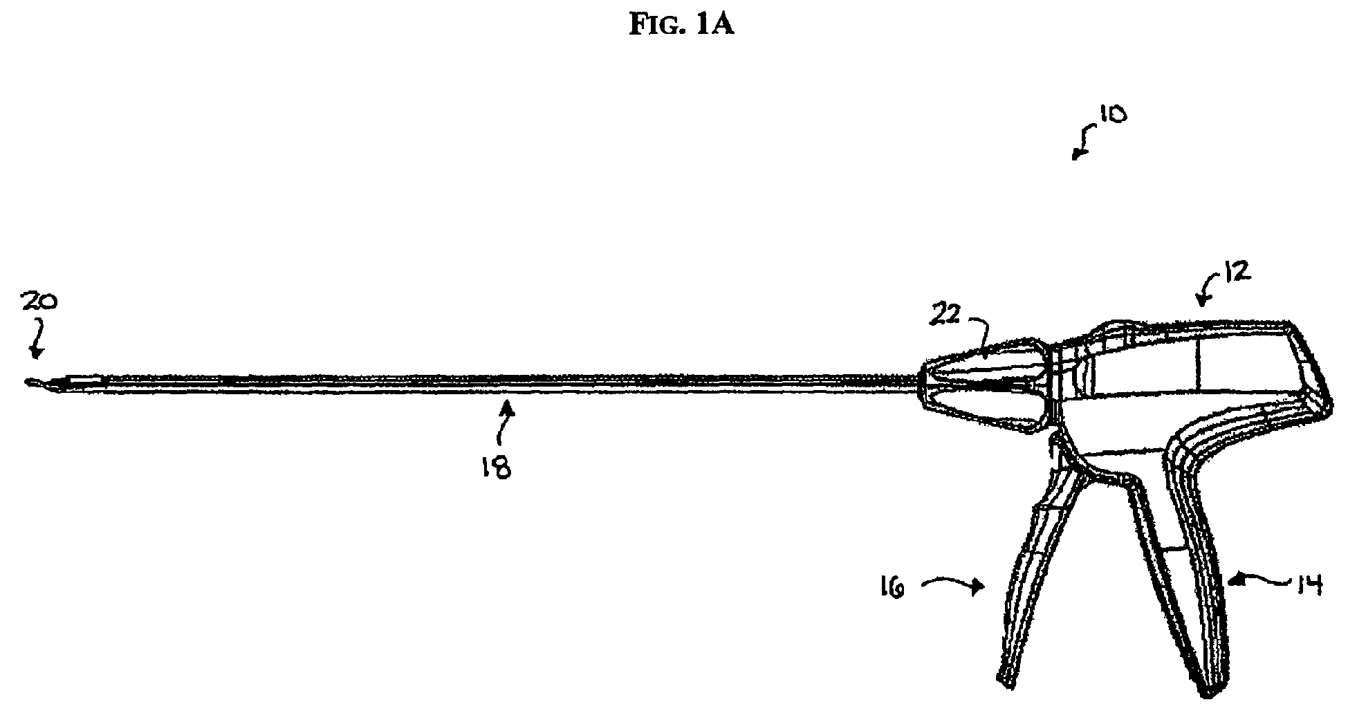
Description
- The present invention relates broadly to surgical devices, and in particular to methods and devices for applying surgical clips to ducts, vessels, shunts, etc.
- In recent years surgery has markedly advanced through the performance of laparoscopic and endoscopic surgical procedures such as cholecystectomies, gastrostomies, appendectomies, and hernia repair. These procedures are accomplished through a trocar assembly, which is a surgical instrument used to puncture a body cavity. The trocar typically contains a sharpened obturator tip and a trocar tube or cannula. The trocar cannula is inserted into the skin to access the body cavity, by using the obturator tip to penetrate the skin. After penetration, the obturator is removed and the trocar cannula remains in the body. It is through this cannula that surgical instruments are placed.
- One surgical instrument that is commonly used with a trocar cannula is a surgical clip applier for ligating a blood vessel, a duct, shunt, or a portion of body tissue during surgery. Most clip appliers typically have a handle with an elongate shaft having a pair of movable opposed jaws formed on an end thereof for holding and forming a ligation clip therebetween. The jaws are positioned around the vessel or duct, and the clip is crushed or formed on the vessel by the closing of the jaws.
- In many of the prior art clip appliers, the feeding and forming mechanisms require precise timing and coordinated movement of components to operate. This need for precise timing and control has resulted in the need for complex mechanical designs, thereby increasing the cost of the clip appliers. Many prior art clip appliers also use a spring-loaded clip advancing assembly to advance one or more clips through the shaft of the device. As a result, the jaws must contain a mechanism for preventing accidental projection of the clip from the device before the clip is formed. Other drawbacks of current clip appliers include the inability to handle an overload applied to the jaws by the trigger under a variety of conditions. Many devices require full closure of the jaws, which can result in overload on the jaws when the vessel or duct positioned therebetween is too large to allow full closure, or when a foreign object is positioned between the jaws.
- Accordingly, there remains a need for improved methods and devices for applying surgical clips to vessels, ducts, shunts, etc.
- The present invention provides method and devices for applying a surgical clip to a vessel, duct, shunt, etc. In one exemplary embodiment, a surgical clip applier is provided having a housing with a trigger movably coupled thereto and an elongate shaft extending therefrom with opposed jaws formed on a distal end thereof. The trigger is adapted to advance a clip to position the clip between the jaws, and to move the jaws from an open position to a closed position to crimp the clip positioned therebetween.
- The surgical clip applier can have a variety of configurations, and it can include a variety of features to facilitate advancement and formation of a surgical clip. In one embodiment, the surgical clip applier can include a feeder shoe that is slidably disposed within the elongate shaft and that is adapted to drive at least one surgical clip through the elongate shaft. In an exemplary embodiment, the feeder shoe can be adapted to move only in a distal direction, such that proximal movement of the feeder shoe is substantially prevented. The elongate shaft can also include a clip track disposed therein and adapted to seat at least one surgical clip. The feeder shoe can be slidably disposed within the clip track.
- A variety of techniques can be used to facilitate distal movement and prevent proximal movement of the feeder shoe. In one exemplary embodiment, the feeder shoe can include a tang adapted to engage the clip track to prevent proximal movement of the feeder shoe within the clip track, yet allow distal movement of the feeder shoe within the clip track. The clip track can include several openings formed therein for receiving the tang to prevent proximal movement of the feeder shoe within the clip track. In another exemplary embodiment, the feeder shoe can include a tang and the feed bar can include several detents formed therein and adapted to engage the tang to move the feeder shoe distally when the feed bar is moved distally.
- In another embodiment, the elongate shaft can include a feed bar slidably disposed therein and coupled to the trigger such that movement of the trigger toward a closed position is adapted to advance the feed bar distally thereby advancing the feeder shoe distally. By way of non-limiting example, the feed bar can be coupled to the trigger by a trigger insert that is mated to the trigger, and by a link that extends between the trigger insert and the proximal end of the feed bar. The proximal end of the feed bar can include a coupler that is adapted to receive a portion of the link. The feed bar can also include a distal end having an advancer that is adapted to engage a distal-most clip and to drive the distal-most clip into the jaws. In certain exemplary embodiments, the feed bar can be adapted to engage and initiate advancement of a distal-most clip into the jaws prior to initiating advancement of the feeder shoe.
- In another embodiment, a clip advancing assembly for advancing a clip through a surgical clip applier is provided. The clip advancing assembly can be used with a variety of surgical clip appliers, including those known in the art. In one exemplary embodiment, the clip advancing assembly can include a clip track that is adapted to seat at least one clip, and a feeder shoe that is adapted to slidably mate to the clip track and to move in a distal direction to move at least one clip disposed within the clip track in a distal direction. The feeder shoe can include, in one exemplary embodiment, a tang that is adapted to engage the clip track to prevent proximal movement of the feeder shoe within the clip track, and that is adapted to allow distal movement of the feeder shoe within the clip track. The clip track can include a plurality of openings formed therein for receiving the tang to prevent proximal movement of the feeder shoe within the clip track.
- The clip advancing assembly can also include a feed bar that is adapted to couple to a movable trigger formed on a housing of a surgical clip applier and that is adapted to slidably move distally when the trigger is closed to advance the feeder shoe and at least one clip disposed within the clip track. The feed bar can have a variety of configurations, and in one exemplary embodiment the distal end of the feed bar can include an advancer that is adapted to engage a distal-most clip to drive the distal-most clip from the clip track into jaws formed on a distal end of a surgical clip applier. In another exemplary embodiment, the feeder shoe can include a tang, and the feed bar can include a plurality of detents formed therein that are adapted to engage the tang to move the feeder shoe distally when the feed bar is moved distally. In use, the proximal end of the feed bar can include a coupler that is adapted to receive a link for coupling the feed bar to a trigger of a surgical clip applier.
- An exemplary method for advancing a surgical clip through an elongate shaft of a surgical clip applier is also provided. In one embodiment, a feed bar can be distally advanced within an elongate shaft of a surgical clip applier to distally drive a feeder shoe disposed within the elongate shaft and thereby distally advance at least one clip. The feed bar can be distally advanced by, for example, actuating a trigger coupled to a housing that is mated to a proximal end of the elongate shaft. In one exemplary embodiment, when the feed bar is distally advanced, an advancer on the distal end of the feed bar can engage a distal-most clip and advance the clip between opposed jaws formed on a distal end of the elongate shaft. The method can also include proximally retracting the feed bar within the elongate shaft while the feeder shoe is maintained in a substantially fixed position.
- In another exemplary embodiment, a method for applying a surgical clip is provided and includes moving a trigger coupled to a housing a first distance toward a closed position to actuate a clip advancing assembly disposed within the housing, thereby advancing a clip into a jaw assembly formed on a distal end of the elongate shaft, and further moving the trigger a second distance toward the closed position to actuate a clip forming assembly disposed within the housing, thereby forming the clip disposed within the jaw assembly. The trigger is preferably pliant relative to the clip advancing assembly during actuation of the clip forming assembly. The clip forming assembly can also be pliant relative to the jaw assembly during actuation thereof.
- In other aspects, an overload mechanism is provided for use with a surgical device. In one exemplary embodiment, the overload mechanism can include a force-receiving member pivotally and slidably disposed in a housing and having a surface with a first end and an opposed second end, and a biasing assembly disposed in the housing and adapted to resist movement of the force-receiving member. In an exemplary embodiment, the resistance increases from the first end to the second end.
- The force-receiving member can have a variety of configurations, but in one embodiment the force-receiving surface formed thereon is positioned within an opening in the housing. The force-receiving surface can include a first portion that is adapted to receive a force for pivotally moving the force-receiving member within the housing, and a second portion that is adapted to receive a force for slidably moving the force-receiving member within the housing. The biasing assembly can also have a variety of configurations, but in one exemplary embodiment the biasing assembly can include a spring disposed around a spring post, and a plunger slidably disposed relative to the spring post and having a head formed thereon and adapted to compress the spring upon slidable movement of the plunger toward the spring post.
- In another embodiment, the housing can include a pivoting assembly that is coupled between the force-receiving member and the biasing assembly such that pivoting assembly is adapted to transfer a force applied to the force-receiving member to the biasing assembly to overcome the resistance. In one exemplary embodiment, the pivoting assembly can include a toggle link that is pivotally coupled to the force-receiving member, and a pivot link that is pivotally coupled to the toggle link and that is adapted to apply a force to the biasing assembly upon pivotal movement thereof.
- In another embodiment, a surgical clip applier is provided having an overload mechanism for preventing overload of a closing force applied to jaws of the clip applier. In one exemplary embodiment, the surgical clip applier can include a housing having a trigger movably coupled thereto, an elongate shaft extending from the housing with opposed jaws formed on a distal end thereof and movable between an open position and a closed position, and a camming assembly disposed within the housing and the elongate shaft and coupled to the trigger. The camming assembly can be adapted to apply a closing force to the jaws upon actuation of the trigger to move the jaws from the open position toward the closed position. The camming assembly can also be adapted to transfer the closing force to an overload mechanism disposed within the housing when the closing force is greater than a resistance of the overload mechanism that is applied to the camming assembly. In an exemplary embodiment, the resistance of the overload mechanism correlates to a force required to move the jaws from the open position toward the closed position.
- While various techniques can be used to couple the camming assembly to the overload mechanism, in one exemplary embodiment the camming assembly moves relative to a force-receiving surface of the overload mechanism such that the closing force of the camming assembly is applied across the force-receiving surface of the overload mechanism as the trigger is actuated to cause the camming assembly to move the jaws from the open position toward the closed position. The force-receiving surface of the overload mechanism can be adapted to resist movement in a proximal direction and the resistance can increase as the trigger is actuated to cause the camming assembly to move relative to the force-receiving surface and to move the jaws from the open position toward the closed position.
- In another exemplary embodiment, the overload mechanism can include a housing having a profile link slidably and pivotally disposed therein and having the force-receiving surface formed thereon and positioned adjacent to an opening formed in the housing. The force-receiving surface can include a first portion that is adapted to receive a force for pivotally moving the force-receiving member within the housing, and a second portion that is adapted to receive a force for slidably moving the force-receiving member within the housing. The overload mechanism can also include a biasing assembly that is adapted to apply a resistance to the profile link. In one exemplary embodiment, the biasing assembly can be coupled to the profile link by a pivoting assembly that is adapted to pivot upon pivotal movement of the profile link, and that is adapted to slide upon slidable movement of the profile link to apply a force to the biasing assembly to overcome the resistance.
- Methods for applying a surgical clip applier having an overload mechanism are also provided. In one exemplary embodiment, a closing force can be applied to a pair of opposed jaws formed on a surgical clip applier. The closing force can be effective to move the opposed jaws from an open position to a closed position. When the closing force is greater than a threshold force of an overload mechanism, the closing force is transferred to the overload mechanism disposed within the surgical clip applier. In an exemplary embodiment, the threshold force of the overload mechanism increases as the jaws are moved from an open position toward the closed position.
- While the overload mechanism can have a variety of configurations, in one embodiment the overload mechanism can include a force-receiving element that is adapted to receive the closing force, and a biasing assembly that is adapted to resist movement of the force-receiving element in response to the closing force. The surgical clip applier can include a camming assembly that is adapted to apply the closing force to the jaws, and that includes a roller member that rolls across the force-receiving element as the closing force is applied to the jaws. The threshold force of the overload mechanism can increase as the roller member rolls across the force-receiving element. In particular, when the roller member rolls across a first portion of the force-receiving element, the force-receiving elements can pivot if the closing force is greater than the threshold force, and when the roller member rolls across a second portion of the force-receiving element, the force-receiving element can slide if the closing force is greater than the threshold force. In an exemplary embodiment, the threshold force required to pivot the force-receiving element is less than the threshold force required to slide the force-receiving element.
- In other aspects, a surgical clip applier is provided and it can include a clip advancing assembly coupled to a trigger and adapted to advance at least one surgical clip through an elongate shaft extending from a housing, and a clip forming assembly coupled to a trigger and adapted to actuate a jaw assembly formed on a distal end of the elongate shaft to form a surgical clip. The trigger can be coupled to the housing and adapted to actuate the clip advancing assembly and the clip forming assembly. In an exemplary embodiment, the trigger has two sequential stages of actuation. The trigger can be effective to actuate the clip advancing assembly during the first stage of actuation, and it can be effective to actuate the clip forming assembly during the second stage of actuation while being pliant relative to the clip advancing assembly.
- The invention will be more fully understood from the following detailed description taken in conjunction with the accompanying drawings, in which:
- FIG. 1A is a side view of one exemplary embodiment of a surgical clip applier;
- FIG. 1B is an exploded view of the surgical clip applier shown in FIG. 1A;
- FIG. 2A is a top view of a jaw retainer assembly of the surgical clip applier shown in FIG. 1A;
- FIG. 2B is a bottom view of the jaw retainer assembly shown in FIG. 2A;
- FIG. 2C is a side view of the jaw retainer assembly shown in FIG. 2B;
- FIG. 2D is a cross-sectional view of the jaw retainer assembly shown in FIG. 2C taken across line D-D;
- FIG. 3A is a top view of a feeder shoe for use with the jaw retainer assembly shown in FIGS. 2A-2D;
- FIG. 3B is a bottom view of the feeder shoe shown in FIG. 3A;
- FIG. 4A is a side perspective view of a feed bar that is configured to advance the feeder shoe of FIGS. 3A and 3B through the jaw retainer assembly shown in FIGS. 2A-2D;
- FIG. 4B is a side view of the proximal end of the feed bar shown in FIG. 4A and the proximal end of the jaw retainer shaft shown in FIGS. 2A and 2B, showing the feed bar in a proximal-most position;
- FIG. 4C is a side view of the feed bar and jaw retainer shaft shown in FIG. 4B, showing the feed bar in a distal-most position;
- FIG. 4D is a side view of another embodiment of a proximal end of a feed bar shown in connection with the proximal end of the jaw retainer shaft shown in FIGS. 2A and 2B, showing the feed bar in the proximal-most position;
- FIG. 4E is a side view of the feed bar and jaw retainer shaft shown in FIG. 4D, showing the feed bar in a distal-most position;
- FIG. 4F is a side view of yet another embodiment of a proximal end of a feed bar shown in connection with the proximal end of the jaw retainer shaft shown in FIGS. 2A and 2B, showing the feed bar in the proximal-most position;
- FIG. 4G is a side view of the feed bar and jaw retainer shaft shown in FIG. 4F, showing the feed bar in an intermediate position;
- FIG. 4H is a side view of the feed bar and jaw retainer shaft shown in FIG. 4F, showing the feed bar in a distal-most position;
- FIG. 5A is a side perspective view of an advancer that is configured to couple to a distal end of the feed bar shown in FIG. 4A;
- FIG. 5B is a side perspective view of another embodiment of an advancer that is configured to couple to a distal end of the feed bar shown in FIG. 4A;
- FIG. 6A is a cross-sectional view of a clip advancing assembly, which includes the jaw retainer assembly shown in FIGS. 2A-2D, the feeder shoe shown in FIGS. 3A-3B, and the feed bar shown in FIG. 4A, showing the feed bar in an initial, proximal position relative to the clip track of the jaw retainer assembly;
- FIG. 6B is a cross-sectional view of the clip advancing assembly shown in FIG. 6A, showing the feed bar moved in a distal direction;
- FIG. 6C is a cross-sectional view of the clip advancing assembly shown in FIG. 6B, showing the feed bar moved further distally, thereby moving the feeder shoe and a clip supply disposed distally of the feeder shoe in a distal direction;
- FIG. 6D is a cross-sectional view of the clip advancing assembly shown in FIG. 6C, showing the feed bar returned to the initial, proximal position, shown in FIG. 6A, while the feeder shoe and clip supply remain in the advanced position shown in FIG. 6C;
- FIG. 6E is a bottom perspective view of the advancer shown in FIG. 5A disposed within the clip track of the jaw retainer assembly shown in FIGS. 2A-2D, showing the advancer in a proximal-most position;
- FIG. 6F is a bottom perspective view of the advancer shown in FIG. 6E, showing the advancer in a distal-most position after advancing a clip into the jaws of the surgical clip applier;
- FIG. 7 is a side perspective view of a pair of jaws of the surgical clip applier shown in FIG. 1A;
- FIG. 8 is a side perspective view of a cam for use with the jaws shown in FIG. 7;
- FIG. 9 is a top perspective view of a push rod that is adapted to couple to the cam shown in FIG. 8 for moving the cam relative to the jaws shown in FIG. 7;
- FIG. 10A is a top view of the cam shown in FIG. 8 coupled to the jaws shown in FIG. 7, showing the cam in an initial position and the jaws open;
- FIG. 10B is a top view of the cam shown in FIG. 8 coupled to the jaws shown in FIG. 7, showing the cam advanced over the jaws and the jaws in a closed position;
- FIG. 11 is a top perspective view of a tissue stop that is adapted to couple to a distal end of the clip track of the jaw retainer assembly shown in FIGS. 2A-2D;
- FIG. 12 is a top view of a distal end of the surgical clip applier shown in FIG. 1A showing the tissue stop shown in FIG. 11 positioned between the jaws shown in FIG. 7;
- FIG. 13 is a side, partially cross-sectional view of the handle portion of the surgical clip applier shown in FIG. 1A;
- FIG. 14 is a side perspective view of a trigger insert of the surgical clip applier shown in FIG. 1A;
- FIG. 15A is a side perspective view of one half of a feed bar coupler of the surgical clip applier shown in FIG. 1A;
- FIG. 15B is a side perspective view of the other half of the feed bar coupler shown in FIG. 15A;
- FIG. 16 is a top perspective view of a flexible link that forms part of a clip advancing assembly of the surgical clip applier shown in FIG. 1A;
- FIG. 17A is a side, partially cross-sectional view of a portion of the handle of the surgical clip applier shown in FIG. 1A, showing a clip advancing assembly in an initial position;
- FIG. 17B is a side, partially cross-sectional view of a portion of the handle of the surgical clip applier shown in FIG. 17A, showing the clip advancing assembly partially actuated;
- FIG. 17C is a side, partially cross-sectional view of a portion of the handle of the surgical clip applier shown in FIG. 17B, showing the clip advancing assembly fully actuated;
- FIG. 17D is a side, partially cross-sectional view of a portion of the handle of the surgical clip applier shown in FIG. 17A, showing a clip forming assembly actuated;
- FIG. 18 is a side view of a closure link roller that forms part of a clip forming assembly of the surgical clip applier shown in FIG. 1A;
- FIG. 19 is a top perspective view of a closure link that couples to the closure link roller shown in FIG. 18 to form part of a clip forming assembly of the surgical clip applier shown in FIG. 1A;
- FIG. 20A is a top perspective view of a closure link coupler that couples to the closure link shown in FIG. 19 and that also forms part of the clip forming assembly of the surgical clip applier shown in FIG. 1A;
- FIG. 20B is a bottom view of the closure link shown in FIG. 20A coupled to the push rod of FIG. 9 and having one embodiment of a biasing element disposed therein;
- FIG. 20C is a bottom view of the closure link shown in FIG. 20A coupled to the push rod of FIG. 9 and having another embodiment of a biasing element disposed therein;
- FIG. 21A is an enlarged side perspective view of an anti-backup mechanism of the surgical clip applier shown in FIG. 1A;
- FIG. 21B is a perspective view of a pawl mechanism of the anti-backup mechanism shown in FIG. 21 A;
- FIG. 22A is a side, partially cross-sectional view of a portion of the handle of the surgical clip applier shown in FIG. 1A, showing the anti-backup mechanism in an initial position;
- FIG. 22B is a side, partially cross-sectional view of a portion of the handle of the surgical clip applier shown in FIG. 22A, showing the anti-backup mechanism in a partially actuated position;
- FIG. 22C is a side, partially cross-sectional view of a portion of the handle of the surgical clip applier shown in FIG. 22B, showing the anti-backup mechanism in a fully actuated position;
- FIG. 22D is a side, partially cross-sectional view of a portion of the handle of the surgical clip applier shown in FIG. 22C, showing the anti-backup mechanism returning to an initial position;
- FIG. 22E is a side, partially cross-sectional view of a portion of the handle of the surgical clip applier shown in FIG. 22D, showing the anti-backup mechanism returned to the initial position;
- FIG. 23A is an exploded view of an overload mechanism of the surgical clip applier shown in FIG. 1A;
- FIG. 23B is a partially cross-sectional view of the overload mechanism shown in FIG. 23A, showing the closure link roller first coming into contact with the profile link;
- FIG. 23C is a partially cross-sectional view of the overload mechanism shown in FIG. 23B, showing the closure link roller applying a force to the profile link causing the profile link to pivot;
- FIG. 23D is a perspective view of another embodiment of an overload mechanism for use with a surgical clip applier;
- FIG. 24A is a side perspective view of a clip quantity indicator wheel of the surgical clip applier shown in FIG. 1A;
- FIG. 24B is a side view of a clip quantity indicator wheel shown in FIG. 24A;
- FIG. 25 is a top perspective view of a clip quantity actuator for use with the clip quantity indicator wheel shown in FIG. 24;
- FIG. 26A is a side, partially cross-sectional view of a portion of the handle of the surgical clip applier shown in FIG. 1A, showing movement of the clip quantity actuator of FIG. 25 and the clip quantity indicator wheel of FIG. 24; and
- FIG. 26B is a side, partially cross-sectional view of a portion of the handle of the surgical clip applier shown in FIG. 26A, showing further movement of the clip quantity actuator of FIG. 25 and the clip quantity indicator wheel of FIG. 24.
- The present invention generally provides a surgical clip applier and methods for using a surgical clip applier to apply surgical clips to a vessel, duct, shunt, etc., during a surgical procedure. An exemplary surgical clip applier can include a variety of features to facilitate application of a surgical clip, as described herein and illustrated in the drawings. However, a person skilled in the art will appreciate that the surgical clip applier can include only some of these features and/or it can include a variety of other features known in the art. The surgical clip applier described herein is merely intended to represent certain exemplary embodiments.
- FIG. 1A illustrates one exemplary
surgical clip applier 10. As shown, theclip applier 10 generally includes ahousing 12 having astationary handle 14 and a movable handle or trigger 16 that is pivotally coupled to thehousing 12. Anelongate shaft 18 extends from thehousing 12 and it includes a pair ofopposed jaws 20 formed on a distal end thereof for crimping a surgical clip. Theelongate shaft 18 can be rotatably coupled to thehousing 12, and it can include arotation knob 22 for rotating theshaft 18 relative to thehousing 12. FIG. 1B illustrates an exploded view of thesurgical clip applier 10 shown in FIG. 1A, and the various components will be described in more detail below. - FIGS. 2A-12 illustrate exemplary embodiments of the various components of the
shaft 18 of thesurgical clip applier 10. In general, referring to FIG. 1B, theshaft 18 includes anouter tube 24 that houses the shaft components, which can include ajaw retaining assembly 26 having ajaw retainer shaft 28 with aclip track 30 and apush rod channel 32 formed thereon. Thejaws 20 can be configured to mate to a distal end of theclip track 30. Theshaft assembly 18 can also include a clip advancing assembly, which in one exemplary embodiment can include afeeder shoe 34 that is adapted to be slidably disposed within theclip track 30 to advance a series ofclips 36 positioned therein, and afeed bar 38 that is adapted to drive thefeeder shoe 34 through theclip track 30. Thefeed bar 38 can include anadvancer assembly 40 that is adapted to mate to a distal end thereof for advancing a distal-most clip into thejaws 20. Theshaft assembly 18 can also include a clip forming or camming assembly, which in one exemplary embodiment can include acam 42 that is adapted to slidably mate to thejaws 20, and apush rod 44 that can couple to thecam 42 to move thecam 42 relative to thejaws 20. The shaft assembly can also include atissue stop 46 that can mate to a distal end of theclip track 30 for facilitating positioning of thejaws 20 relative to a surgical site. - The various components of one exemplary clip advancing assembly are shown in more detail in FIGS. 2A-5. Referring first to FIGS. 2A-2D, the
jaw retaining assembly 26 is shown and it includes an elongate, substantially planarjaw retainer shaft 28 having aproximal end 28a that mates to theouter tube 24, and a distal end 28b that is adapted to mate to thejaws 20. While a variety of techniques can be used to mate theproximal end 28a of thejaw retainer shaft 28 to theouter tube 24, in the illustrated embodiment theproximal end 28a includesteeth 31 formed on opposed sides thereof that are adapted to be received within corresponding holes or openings (not shown) formed in theouter tube 24, and a cut-out 29 formed therein that allows the opposed sides of theproximal end 28a to deflect or to form a spring. In particular, the cut-out 29 allows the opposed sides of theproximal end 28a of thejaw retainer shaft 28 to be compressed toward one another when thejaw retainer shaft 28 is inserted in theouter tube 24. Once theteeth 31 are aligned with the corresponding openings in theouter tube 24, theproximal end 28a of thejaw retainer shaft 28 will return to its original, uncompressed configuration thereby causing theteeth 31 to extend into the corresponding openings to engage the outer 24. As will be discussed in more detail below with respect to FIG. 4A, the device can also include a feature to prevent compression of the opposed sides of theproximal end 28a of thejaw retainer shaft 28 during use of the device to prevent accidental disengagement of theteeth 31 from theouter tube 24. - A variety of techniques can also be used to mate the distal end 28b of the
jaw retainer shaft 28 to thejaws 20, however in the illustrated embodiment the distal end 28b of thejaw retainer shaft 28 includes several cut-outs orteeth 78 formed therein for mating with corresponding protrusions orteeth 94 formed on thejaws 20, which will be discussed in more detail below with respect to FIG. 7. Theteeth 78 allow a proximal portion of thejaws 20 to be substantially co-planar with thejaw retainer shaft 28. - The
jaw retaining assembly 26 can also include apush rod channel 32 formed thereon for slidably receiving thepush rod 44, which is used to advanced thecam 42 over thejaws 20, as will be discussed in more detail below. Thepush rod channel 32 can be formed using a variety of techniques, and it can have any shape and size depending on the shape and size of thepush rod 44. As shown in FIG. 2D, thepush rod channel 32 is fixedly attached, e.g., by welding, to a superior surface of theretainer shaft 28, and it has a substantially rectangular shape and defines apathway 32a extending therethrough. Thepush rod channel 32 can also extend along all or only a portion of theretainer shaft 28. A person skilled in the art will appreciate that thejaw retaining assembly 26 does not need to include apush rod channel 32 for facilitating movement of thepush rod 44 within theelongate shaft 18 of thesurgical clip applier 10. - As is further shown in FIGS. 2A-2D, the
jaw retaining assembly 26 can also include aclip track 30 mated thereto or formed thereon. Theclip track 30 is shown mated to an inferior surface of thejaw retainer shaft 28, and it extends distally beyond the distal end 28b of thejaw retainer shaft 28 to allow a distal end 30b of theclip track 30 to be substantially aligned with thejaws 20. In use, theclip track 30 is configured to seat at least one, and preferably a series, of clips therein. Accordingly, theclip track 30 can include opposedside rails clip track 30 can be configured to seat about twenty clips that are pre-disposed within theclip track 30 during manufacturing. A person skilled in the art will appreciate that the shape, size, and configuration of theclip track 30 can vary depending on the shape, size, and configuration of clips, or other closure devices such as staples, adapted to be received therein. Moreover, a variety of other techniques can be used, instead of aclip track 30, to retain a clip supply with theelongate shaft 18. - The
clip track 30 can also includeseveral openings 30c formed therein for receiving atang 82a formed on afeeder shoe 34 adapted to be disposed within theclip track 30, as will be discussed in more detail below. In an exemplary embodiment, theclip track 30 includes a quantity ofopenings 30c that corresponds to at least the number of clips adapted to be pre-disposed within thedevice 10 and applied during use. Theopenings 30c are preferably equidistant from one another to ensure that thetang 82a on thefeeder shoe 34 engages anopening 30c each time thefeeder shoe 34 is advanced. While not shown, theclip track 30 can include detents, rather thanopenings 30c, or it can include other features that allow theclip track 30 to engage thefeeder shoe 34 and prevent distal movement, yet allow proximal movement, of thefeeder shoe 34. Theclip track 30 can also include astop tang 118 formed thereon, as shown in FIG. 2B, that is effective to be engaged by a corresponding stop tang formed on thefeeder shoe 34 to prevent movement of thefeeder shoe 34 beyond a distal-most position, as will be discussed below. Thestop tang 118 can have a variety of configurations, but in one exemplary embodiment it is in the form of two adjacent tabs that extend toward one another to enclose a portion of the clip track, thus allowing clips to pass therethrough. - An
exemplary feeder shoe 34 is shown in more detail in FIGS. 3A and 3B, and it can be adapted to directly driving clips through theclip track 30. While thefeeder shoe 34 can have a variety of configurations, and a variety of other techniques can be used to drive clips through theclip track 30, in an exemplary embodiment thefeeder shoe 34 has a generally elongate shape with proximal anddistal ends 34a, 34b. The distal end 34b can be adapted to cradle the proximal-most clip in theclip track 30 to push the clip(s) through theclip track 30. In the illustrated exemplary embodiment, the distal end 34b is substantially v-shaped for seating a v-shaped bight portion of a clip. The distal end 34b also includes a rectangular-shapednotch 34c formed therein for allowing the advancer 40 to engage a distal-most clip and advance it into thejaws 20, as will be discussed in more detail below. The distal end 34b can, of course, vary depending on the configuration of the clip, or other closure mechanism, being used with thedevice 10. - In another exemplary embodiment, the
feeder shoe 34 can also include features to facilitate distal movement of thefeeder shoe 34 within theclip track 30, and to substantially prevent proximal movement of thefeeder shoe 34 within theclip track 30. Such a configuration will ensure advancement and proper positioning of the clips within theclip track 30, thus allowing a distal-most clip to be advanced between thejaws 20 with each actuation of thetrigger 16, as will be discussed in more detail below. In the illustrated exemplary embodiment, thefeeder shoe 34 includes atang 82a formed on a superior surface 34s thereof and angled proximally for engaging one of theopenings 30c formed in theclip track 30. In use, the angle of thetang 82a allows thefeeder shoe 34 to slide distally within theclip track 30. Each time thefeeder shoe 34 is advanced, thetang 82a will move in a distal direction from oneopening 30c to thenext opening 30c in theclip track 30. The engagement of thetang 82a with theopening 30c in theclip track 30 will prevent thefeeder shoe 34 from moving proximally to return to the previous position, as will be described in more detail below. - In order to facilitate proximal movement of the
feeder shoe 34 within theclip track 30, thefeeder shoe 34 can also include a tang 82b formed on the inferior surface 34i thereof, as shown in FIG. 3B, for allowing thefeeder shoe 34 to be engaged by the feed bar 38 (FIG. 4A) as thefeed bar 38 is moved distally. The inferior tang 82b is similar to thesuperior tang 82a in that it can be angled proximally. In use, each time thefeed bar 38 is moved distally, adetent 84 formed in thefeed bar 38 can engage the inferior tang 82b and move thefeeder shoe 34 distally a predetermined distance within theclip track 30. Thefeed bar 38 can then be moved proximally to return to its initial position, and the angle of the inferior tang 82b will allow the tang 82b to slide into thenext detent 84 formed in thefeed bar 38. As previously noted, a variety of other features rather thantangs 82a, 82b andopenings 30c ordetents 84 can be used to control movement of thefeeder shoe 34 within theclip track 30. - As previously mentioned, the
feeder shoe 34 can also include a stop formed thereon that is adapted to stop movement of thefeeder shoe 34 when thefeeder shoe 34 is in the distal-most position and there are no clips remaining in thedevice 10. While the stop can have a variety of configurations, FIGS. 3A and 3B illustrate athird tang 82c formed on thefeeder shoe 34 and extending in an inferior direction for engaging the stop tang 118 (FIG. 2B) formed on theclip track 30. Thethird tang 82c is positioned such that it will engage thestop tang 118 on theclip track 30 when thefeeder shoe 34 is in a distal-most position, thereby preventing movement of thefeeder shoe 34 and thefeed bar 38 when the clip supply is depleted. - FIG. 4A illustrates an
exemplary feed bar 38 for driving thefeeder shoe 34 through theclip track 30 of thejaw retaining assembly 26. As shown, thefeed bar 38 has a generally elongate shape with proximal and distal ends 38a, 38b. The proximal end 38a of the feed bar 38a can be adapted to mate to a feed bar coupler 50 (FIG. 1B), which will be discussed in more detail below. Thefeed bar coupler 50 can mate to afeed link 52 that is effective, upon actuation of thetrigger 16, to slidably move thefeed bar 38 in a distal direction within theelongate shaft 18. The distal end 38b of the feed bar 38b can be adapted to mate to an advancer 40, 40', exemplary embodiments of which are shown in FIGS. 5A and 5B, that is effective to drive a distal-most clip disposed within theclip track 30 into thejaws 20, which will be discussed in more detail below. - As previously mentioned, the proximal end 38a of the
feed bar 38 can include a feature to prevent compression of the opposed sides of theproximal end 28a of the jaw retainer shaft 28 (FIGS. 2A and 2B) during use of the device to prevent accidental disengagement of theteeth 31 from theouter tube 24. In one exemplary embodiment, shown FIGS. 4A-4C, the proximal end 38a of thefeed bar 38 can include aprotrusion 39 formed thereon that is adapted to extend into theopening 29 formed in theproximal end 28a of thejaw retainer shaft 28. When thefeed bar 38 is in a proximal-most position (i.e., when thetrigger 16 is in an open position), theprotrusion 39 will be positioned at the proximal end of theopening 29, as shown in FIG. 4B, allowing theproximal end 28a of thejaw retainer shaft 28 to compress to allow theshaft 28 to slide into theouter tube 24. When thefeed bar 38 is in a distal-most position (i.e., when thetrigger 16 is in at least a partially closed position), theprotrusion 39 will be positioned at an intermediate location adjacent to theteeth 31 as shown in FIG. 4C, to prevent compression of theproximal end 28a of thejaw retainer shaft 28. This is particularly advantageous during use of the device, as theprotrusion 39 will prevent accidental disengagement of thejaw retainer shaft 28 from theouter tube 24 during use of the device. While FIGS. 4A-4C illustrate aprotrusion 39 having a rectangular cross-sectional shape with rounded edges, theprotrusion 39 can have a variety of other shapes and sizes. For example, as shown in FIGS. 4D and 4E, the protrusion 39' has a cross-sectional shape that is somewhat triangular with a tapering end that is adapted to extend between theteeth 31 to further ensure that theproximal end 28a of thejaw retainer shaft 28 can not be compressed during use of the device. More than one protrusion can also be used. For example, FIGS. 4F-4H illustrate another embodiment in which the proximal end 38a' of thefeed bar 38 includes twoprotrusions 39a, 39b formed thereon and spaced a distance apart from one another. The twoprotrusions 39a, 39b will prevent compression of theproximal end 28a of thejaw retainer shaft 28 when thefeed bar 38 is in a proximal-most position, as shown in FIG. 4F, and when thefeed bar 38 is in a distal-most position, as shown in FIG. 4H. Compression of theproximal end 28a of thejaw retainer shaft 28 can only occur when thefeed bar 38 is at an intermediate position such that theteeth 31 are positioned between theprotrusions 39a, 39b, as shown in FIG. 4G. - As was also previously mentioned, the
feed bar 38 can include one ormore detents 84 formed therein for engaging the inferior tang 82b formed on thefeeder shoe 34. The quantity ofdetents 84 can vary, but in an exemplary embodiment thefeed bar 38 has a quantity ofdetents 84 that corresponds to or is greater than a quantity of clips adapted to be delivered by thedevice 10, and more preferably it has onemore detent 84 than the quantity of clips adapted to be delivered by thedevice 10. By way of non-limiting example, thefeed bar 38 can include eighteendetents 84 formed therein for delivering seventeen clips that are pre-disposed within theclip track 30. Such a configuration allows thefeed bar 38 to advance thefeeder shoe 34 seventeen times, thereby advancing seventeen clips into thejaws 20 for application. Thedetents 84 are also preferably equidistant from one another to ensure that thefeeder shoe 34 is engaged and advanced by thefeed bar 38 each time thefeed bar 38 is advanced. - The
feed bar 38 can also include a feature to control the amount of movement of thefeed bar 38 relative to theclip track 30. Such a configuration will ensure that thefeeder shoe 34 is advanced a predetermined distance each time thetrigger 16 is actuated, thereby advancing only a single clip into thejaws 20. While a variety of techniques can be used to control the distal of movement of thefeed bar 38, in an exemplary embodiment thefeed bar 38 can include aprotrusion 86 formed thereon that is adapted to be slidably received within a corresponding slot 88 (FIG. 2B) formed in thejaw retainer shaft 28. The length of theslot 88 is effective to limit movement of theprotrusion 86 therein, thus limiting movement of thefeed bar 38. Accordingly, in use thefeed bar 38 can slide between a fixed proximal position and a fixed distal position with respect to theclip track 30, thereby allowing thefeed bar 38 to advance thefeeder shoe 34 by a predetermined distance with each advancement of thefeed bar 38. - FIG. 5A illustrates one exemplary embodiment of an advancer 40 that is adapted to mate to the distal end 38b of the
feed bar 38 and which is effective to drive a distal-most clip from theclip track 30 into thejaws 20. A variety of techniques can be used to mate the advancer 40 to thefeed bar 38, but in the illustrated embodiment the proximal end 40a of the advancer 40 is in the form of a female connector that is adapted to receive the male connector formed on the distal end 38b of thefeed bar 38. The advancer 40 preferably fixedly mates to thefeed bar 38, however it can optionally be integrally formed with thefeed bar 38. The distal end 40b of thefeed bar 38 is preferably adapted to advance a clip into thejaws 20 and thus the distal end 40b of the advancer 40 can include, for example, a clip-pusher member 90 formed thereon. The clip-pusher member 90 can have a variety of shapes and sizes, but in one exemplary embodiment it has an elongate shape with arecess 92 formed in the distal end thereof for seating the bight portion of a clip. The shape of therecess 92 can vary depending on the particular configuration of the clip. The clip-pusher member 90 can also extend at an angle in a superior direction with respect to a longitudinal axis A of theadvancer 40. Such a configuration allows the clip-pusher member 90 to extend into theclip track 30 to engage a clip, while the remainder of the advancer 40 extends substantially parallel to theclip track 30. FIG. 5B illustrates another exemplary embodiment of a clip-pusher member 90' of an advancer 40'. In this embodiment, the clip-pusher member 90' is slightly more narrow and it has a small recess 92' formed in the distal-most end thereof. In use, the advancer 40 can engage and advance only the distal-most clip disposed within theclip track 30 into thejaws 20. This is due to the positioning of thefeed bar 38, which is slidably movable between a fixed proximal and distal positions, as previously discussed. - FIGS. 6A-6G illustrate the clip advancing assembly in use, and in particular FIGS. 6A-6D illustrate movement of the
feed bar 38 within theclip track 30 to advance thefeeder shoe 34 andclip supply 36, and FIGS. 6E-6F illustrate movement of the advancer 40 to advance a distal-most clip into thejaws 20. The components in thehousing 12 that are used to actuate the clip advancing assembly will be discussed in more detail below. - As shown in FIG. 6A, in the resting position the
feed bar 38 is in a proximal-most position such that theprotrusion 86 is positioned proximally within theelongate slot 88 in thejaw retainer shaft 28. Thefeeder shoe 34 is disposed within theclip track 30 and, assuming thedevice 10 has not yet been used, thefeeder shoe 34 is in a proximal-most position such that thesuperior tang 82a on thefeeder shoe 34 is engaged with the proximal-most orfirst opening 30c1 formed in theclip track 30 to prevent proximal movement of thefeeder shoe 34, and the inferior tang 82b on thefeeder shoe 34 is positioned between thefirst detent 841 and thesecond detent 842 in thefeed bar 38, such that the inferior tang 82b is biased in a superior direction by thefeed bar 38. Thedetents 84 in the feed bar are labeled sequentially as 841, 842, etc., and theopenings 30c in theclip track 30 are labeled sequentially as 30c1, 30c2, etc. As is further shown in FIG. 6A, a series ofclips 36, labeled sequentially as 361, 362, ... 36x with 36x being the distal-most clip, are positioned within theclip track 30 distal of thefeeder shoe 34. - Upon actuation of the
trigger 16, thefeed bar 38 is advanced distally, causing theprotrusion 86 to slide distally within theslot 88. As thefeed bar 38 moves distally, the inferior tang 82b on thefeeder shoe 34 will slide into thefirst detent 841 in thefeed bar 38. Further distal movement of thefeed bar 38 will cause thefirst detent 841 to engage the inferior tang 82b, as shown in FIG. 6B, and to move thefeeder shoe 34 andclip supply protrusion 86 abuts the distal end of theelongate slot 88 in thejaw retainer shaft 28, thefeed bar 38 is prevented from further distal movement. In this position, thefeeder shoe 34 has advanced a predetermined distance to advance theclip supply clip track 30 by a predetermined distance. Thesuperior tang 82a of thefeeder shoe 34 has been advanced into thesecond opening 30c2 in theclip track 30 to prevent proximal movement of thefeeder shoe 34, and the inferior tang 82b on thefeeder shoe 34 is still engaged by thefirst detent 841 in thefeed bar 38. - Movement of the
feed bar 38 from the initial, proximal-most position, shown in FIG. 6A, to the final, distal-most position, shown in FIG. 6C, will also advance thedistal-most clip 36x into thejaws 20. In particular, as shown in FIG. 6E, distal movement of thefeed bar 38 will cause the clip-pusher member 90 of the advancer 40, which is attached to the distal end of thefeed bar 38, to engage thedistal-most clip 36x disposed within theclip track 30 and to advance theclip 36x into thejaws 20, as shown in FIG. 6F. In an exemplary embodiment, the advancer 40 will engage and initiate advancement of thedistal-most clip 36x prior to engaging and initiating advancement of thefeeder shoe 34. As a result thedistal-most clip 36x will advance a distance that is greater than a distance traveled by thefeeder shoe 34. Such a configuration allows only thedistal-most clip 36x to be advanced into thejaws 20 without accidentally advancing an additional clip into thejaws 20. - Once the
clip 36x has been partially or fully formed, thetrigger 16 can be released to release the formedclip 36x. Release of thetrigger 16 will also retract thefeed bar 38 in a proximal direction until theprotrusion 86 returns to the initial proximal-most position within theelongate slot 88, as shown in FIG. 6D. As thefeed bar 38 is retracted proximally, thefeeder shoe 34 will not move proximally since thesuperior tang 82a will engage thesecond opening 30c2 in theclip track 30. The inferior tang 82b will not interfere with proximal movement of thefeed bar 38, and once thefeed bar 38 is in the initial, proximal-most position, as shown, the inferior tang 82b will be positioned between thesecond detent 842 and thethird detent 843 in thefeed bar 38. - The process can be repeated to advance another clip into the
jaws 20. With each actuation of thetrigger 16, the inferior tang 82b will be engaged by the next detent, i.e.,detent 842 formed in thefeed bar 38, thesuperior tang 82a on thefeeder shoe 34 will be moved distally into the next opening, i.e., opening 30c3 on theclip track 30, and the distal-most clip will be advanced into thejaws 20 and released. Where thedevice 10 includes a predetermined amount of clips, e.g., seventeen clips, thetrigger 16 can be actuated seventeen times. Once the last clip has been applied, the stop, e.g., thethird tang 82c, on thefeeder shoe 34 can engage thestop tang 118 on theclip track 30 to prevent further distal movement of thefeeder shoe 34. - FIGS. 7-9 illustrate various exemplary components of a clip forming assembly. Referring first to FIG. 7, an exemplary embodiment of the
jaws 20 are shown. As previously mentioned, thejaws 20 can include aproximal portion 20a having teeth 94 for mating with correspondingteeth 78 formed on thejaw retaining shaft 28. Other techniques can, however, be used to mate thejaws 20 to thejaw retaining shaft 28. For example, a dovetail connection, a male-female connection, etc., can be used. Alternatively, thejaws 20 can be integrally formed with the retainingshaft 28. The distal portion 20b of thejaws 20 can be adapted to receive a clip therebetween, and thus the distal portion 20b can include first and second opposed jaw members 96a, 96b that are movable relative to one another. In an exemplary embodiment, the jaw members 96a, 96b are biased to an open position, and a force is required to move the jaw members 96a, 96b toward one another. The jaw members 96a, 96b can each include a groove (only onegroove 97 is shown) formed therein on opposed inner surfaces thereof for receiving the legs of a clip in alignment with the jaw members 96a, 96b. The jaws members 96a, 96b can also each include acam track 98a, 98b formed therein for allowing thecam 42 to engage the jaw members 96a, 96b and move the jaw members 96a, 96b toward one another. In an exemplary embodiment, thecam track 98a, 98b is formed on a superior surface of the jaw members 96a, 96b. - FIG. 8 illustrates an
exemplary cam 42 for slidably mating to and engaging the jaw members 96, 96b. Thecam 42 can have a variety of configurations, but in the illustrated embodiment it includes aproximal end 42a that is adapted to mate to apush rod 44, discussed in more detail below, and a distal end 42b that is adapted to engage the jaw members 96a, 96b. A variety of techniques can be used to mate thecam 42 to thepush rod 44, but in the illustrated exemplary embodiment thecam 42 includes a female or keyed cut-out 100 formed therein and adapted to receive a male orkey member 102 formed on the distal end 44b of thepush rod 44. Themale member 102 is shown in more detail in FIG. 9, which illustrates thepush rod 44. As shown, themale member 102 has a shape that corresponds to the shape of the cut-out 100 to allow the twomembers cam 42 and thepush rod 44 can optionally be integrally formed with one another. Theproximal end 44a of thepush rod 44 can be adapted to mate to a closure link assembly, discussed in more detail below, for moving thepush rod 44 and thecam 42 relative to thejaws 20. - As is further shown in FIG. 8, the
cam 42 can also include aprotrusion 42c formed thereon that is adapted to be slidably received within anelongate slot 20c formed in thejaws 20. In use, theprotrusion 42c and theslot 20c can function to form a proximal stop for the clip forming assembly. - Referring back to FIG. 8, the distal end 42b of the
cam 42 can be adapted to engage the jaw members 96a, 96b. While a variety of techniques can be used, in the illustrated exemplary embodiment the distal end 42b includes a camming channel or taperingrecess 104 formed therein for slidably receiving the cam tracks 98a, 98b on the jaw members 96a, 96b. In use, as shown in FIGS. 10A and 10B, thecam 42 can be advanced from a proximal position, in which the jaw members 96a, 96b are spaced a distance apart from one another, to a distal position, in which the jaw members 96a, 96b are positioned adjacent to one another and in a closed position. As thecam 42 is advanced over the jaw members 96a, 96b, the taperingrecess 104 will push the jaw members 96a, 96b toward one another, thereby crimping a clip disposed therebetween. - As previously mentioned, the
surgical clip applier 10 can also include atissue stop 46 for facilitating positioning of the tissue at the surgical site withinjaws 20. FIG. 11 shows one exemplary embodiment of atissue stop 46 having proximal end anddistal ends proximal end 46a can be adapted to mate to a distal end of theclip track 30 for positioning thetissue stop 46 adjacent to thejaws 20. However, thetissue stop 46 can be integrally formed with theclip track 30, or it can be adapted to mate to or be integrally formed with a variety of other components of theshaft 18. Thedistal end 46b of thetissue stop 46 can have a shape that is adapted to seat a vessel, duct, shunt, etc. therebetween to position and aligned thejaws 20 relative to the target site. As shown in FIG. 11 thedistal end 46b of thetissue stop 46 is substantially v-shaped. Thedistal end 46b can also have a curved configuration to facilitate placement of the device through a trocar or other access tube. Thedistal end 46b of thetissue stop 46 can also optionally include other features to facilitate movement of the clip there over. For example, as shown in FIG. 11, thetissue stop 46 includes aramp 47 formed at a mid-portion of thedistal end 46b for maintaining a clip in alignment with the tip of theadvancer assembly 40. In particular, theramp 47 can allow the apex of a clip to ride therealong thus preventing the clip from becoming misaligned relative to theadvancer assembly 40 that is pushing the clip in a distal direction. A person skilled in the art will appreciate that thetissue stop 46 can have a variety of other configurations, and it can include a variety of other features to facilitate advancement of a clip therealong. - FIG. 12 illustrates the
tissue stop 46 in use. As shown, thetissue stop 46 is positioned just inferior to thejaws 20 and at a location that allows a vessel, duct, shunt etc. to be received between thejaws 20. As is further shown, asurgical clip 36 is positioned between thejaws 20 such that thebight portion 36a of theclip 36 is aligned with thetissue stop 46. This will allow the legs 36b of theclip 36 to be fully positioned around the vessel, duct, shunt, or other target site. - FIGS. 13-26B illustrate various exemplary internal components of the
housing 12 for controlling clip advancement and forming. As previously discussed, thesurgical clip applier 10 can include some or all of the features disclosed herein, and it can include a variety of other features known in the art. In certain exemplary embodiments, the internal components of theclip applier 10 can include a clip advancing assembly, that couples to the clip advancing assembly of theshaft 18, for advancing at least one clip through theelongate shaft 18 to position the clip between thejaws 20, and a clip forming assembly, that couples to the clip forming assembly of theshaft 18, for closing thejaws 20 to form a partially or fully closed clip. Other exemplary features include an anti-backup mechanism for controlling movement of thetrigger 16, an overload mechanism for preventing overload of the force applied to thejaws 20 by the clip forming assembly, and a clip quantity indicator for indicating a quantity of clips remaining in thedevice 10. - FIGS. 13-16D illustrate an exemplary embodiment of a clip advancing assembly of the
housing 12 for effecting movement of thefeed bar 38 within theshaft 18. In general, the clip advancing assembly can include atrigger insert 48 that is coupled to thetrigger 16, afeed bar coupler 50 that can mate to a proximal end 38a of thefeed bar 38, and afeed link 52 that is adapted to extend between thetrigger insert 48 and thefeed bar coupler 50 for transferring motion from thetrigger insert 48 to thefeed bar coupler 50. - FIG. 14 illustrates the
trigger insert 48 in more detail. The shape of thetrigger insert 48 can vary depending on the other components of thehousing 12, but in the illustrated embodiment thetrigger insert 48 includes acentral portion 48a that is adapted to pivotally mate to thehousing 12, and an elongate portion 48b that is adapted to extend into and mate to thetrigger 16. Thecentral portion 48a can include abore 106 extending therethrough for receiving a shaft for pivotally mating thetrigger insert 48 to thehousing 12. Thecentral portion 48a can also include afirst recess 108 formed in a superior side edge for receiving a portion of thefeed link 52. Thefirst recess 108 preferably has a size and shape that allows a portion of thefeed link 52 to extend therein such that thefeed link 52 will be forced to pivot when thetrigger insert 48 pivots due to movement of thetrigger 16. As shown in FIG. 14, thefirst recess 108 is substantially elongate and includes a substantially circular portion formed therein for seating a shaft formed on a proximal end of thefeed link 52, as will be discussed in more detail with respect to FIG. 16. Thetrigger insert 48 can also include asecond recess 110 formed in a back side edge for receiving aclosure link roller 54 that is coupled to thepush bar 44 for moving thecam 42 to close thejaws 20, and ratchetteeth 112 formed on the bottom side edge thereof for mating with a pawl 60 for controlling movement of thetrigger 16, as will be discussed in more detail below. - The exemplary
feed bar coupler 50 is shown in more detail in FIGS. 15A and 15B, and it can be adapted to couple the proximal end of thefeed bar 38 to the distal end of thefeed link 52. While a variety of techniques can be used to mate thefeed bar coupler 50 to the proximal end 38a of thefeed bar 38, in an exemplary embodiment thefeed bar coupler 50 is formed from two separate halves 50a, 50b that mate together to maintain the proximal end 38a of thefeed bar 38 therebetween. When mated, the two halves 50a, 50b together define a central shaft 50c having substantiallycircular flanges 50d, 50e formed on opposed ends thereof and defining a recess 50f therebetween for seating a distal portion of thefeed link 52. The central shaft 50c defines a lumen 50g therethrough for receiving the proximal end 38a of thefeed bar 38 and for locking thefeed bar 38 in a substantially fixed position relative to thefeed bar coupler 50. Thefeed bar coupler 50 can, however, be integrally formed with thefeed bar 38, and it can have a variety of other shapes and sizes to facilitate mating with thefeed link 52. - FIG. 16 illustrates an
exemplary feed link 52, which can extend between thetrigger insert 48 and thefeed bar coupler 52. In general, thefeed link 52 can have a substantially planar elongate shape with proximal and distal ends 52a, 52b. The proximal end 52a is adapted to rotatably sit within thefirst recess 108 of thetrigger insert 48 and thus, as previously discussed, it can include a shaft 53 (FIG. 1B) extending therethrough. The shaft 53 can be adapted to pivotally rotate within thefirst recess 108 of thetrigger insert 48, thereby allowing thetrigger insert 48 to pivot thefeed link 52. The distal end 52b of thefeed link 52 can be adapted to couple to feedbar coupler 50 and thus, in an exemplary embodiment, it includes opposed arms 114a, 114b formed thereon and defining anopening 116 therebetween for seating the central shaft 50a of thefeed bar coupler 50. The arms 114a, 114b are effective to engage and move thecoupler 50 as thefeed link 52 pivots about a pivot axis X. The pivot axis X can be defined by the location at which thefeed link 52 couples to thehousing 12, and it can be positioned anywhere on thefeed link 52, but in the illustrated embodiment it is positioned adjacent to the proximal end 52a of thefeed link 52. - In an exemplary embodiment, the
feed link 52 can be flexible to eliminate the need to calibrate the clip advancing assembly and the clip forming assembly. In particular, thefeed link 52 allows thetrigger 16 to continue moving toward a closed position even after thefeed bar 38 andfeed bar coupler 50 are in a distal-most position, and it provides some freedom to the clip forming and clip advancing assemblies. In other words, thetrigger 16 is pliant relative to thefeed bar 38 during closure of the trigger. - The particular stiffness and strength of the
feed link 52 can vary depending on the configuration of the clip advancing assembly and the clip forming assembly, but in one exemplary embodiment thefeed link 52 has a stiffness that is in the range of 75 to 110 lbs per inch, and more preferably that is about 93 lbs per inch (as measured at the interface between thelink 52 and the feed bar coupler 50), and it has a strength of that is in the range of 25 lbs and 50 lbs, and more preferably that is about 35 lbs. Thefeed link 52 can also be formed from a variety of materials, including a variety of polymers, metals, etc. One exemplary material is a glass-reinforced polyetherimide, but a number of reinforced thermoplastics could be used, including glass reinforced liquid-crystal polymers, glass-reinforced nylons, and carbon-fiber reinforced versions of these and similar thermoplastics. Fiber-reinforced thermoset polymers such as thermoset polyesters could also be used.Feed link 52 could also be fabricated from a metal, such as spring steel to achieve the desired combination of limited flexibility and controlled strength. - FIGS. 17A-17D illustrate the exemplary clip advancing assembly in use. FIG. 17A shows an initial position, wherein the
trigger 16 is resting in an open position, thefeed bar coupler 50 andfeed bar 38 are in a proximal-most position, and thefeed link 52 extends between thetrigger insert 48 and thefeed bar coupler 50. As previously discussed, in the initial open position theprotrusion 86 on thefeed bar 38 in positioned in the proximal end of theelongate slot 88 in thejaw retainer shaft 28. A first biasing member, e.g.,spring 120, is coupled to thetrigger insert 48 and thehousing 12 to maintain thetrigger insert 48 and trigger 16 in the open position, and a second biasing member, e.g.,spring 122, extends between ashaft coupler 124, which rotatably mates theshaft 18 to thehousing 12, and thefeed bar coupler 50 to maintain thefeed bar coupler 50 andfeed bar 38 in the proximal-most position. - When the
trigger 16 is actuated and moved toward the closed position, i.e., toward thestationary handle 14, to overcome the biasing forces applied by thesprings trigger insert 48 begins to pivot in a counter-clockwise direction, as shown in FIG. 17B. As a result, thefeed link 52 is forced to pivot in a counter-clockwise direction, thereby moving thefeed bar coupler 50 andfeed bar 38 in a distal direction. Theprotrusion 86 on thefeed bar 38 thus moves distally within theelongate slot 88 in thejaw retainer shaft 28, thereby advancing thefeeder shoe 34 and theclips 36 disposed within the clip track.Spring 120 is extended between the housing and thetrigger insert 48, andspring 122 is compressed between thefeed bar coupler 50 and theshaft coupler 124. - As the
trigger 16 is further actuated and thetrigger insert 48 continues to pivot, thefeed bar coupler 50 andfeed bar 38 will eventually reach a distal-most position. In this position, theprotrusion 86 on thefeed bar 38 will be positioned at the distal end of theslot 88 in thejaw retainer shaft 28 and a clip will be positioned between thejaws 20, as previously discussed.Spring 122 will be fully compressed between theshaft coupler 124 and thefeed bar coupler 50, and thefeed link 52 will flex, as shown in FIGS. 17C and 17D. As thefeed link 52 flexes, and more preferably once thefeed link 52 fully flexed, the clip forming assembly will be actuated to close thejaws 20. Thefeed link 52 will remain flexed during actuation of the clip forming assembly, e.g., the second stage of actuation, such that thetrigger insert 48 is pliant relative to the clip advancing assembly, and in particular thefeed bar 38. - An exemplary clip forming assembly of the
housing 12 is shown in more detail in FIGS. 18-20. In general, the clip forming assembly is disposed within thehousing 12 and it is effective to move thepush rod 44 andcam 42 relative to thejaws 20 to move thejaws 20 to a closed position and thereby crimp a clip positioned therebetween. While the clip forming assembly can have a variety of configurations, the illustrated exemplary clip forming assembly includes aclosure link roller 54 that is slidably coupled to thetrigger insert 48, aclosure link 56 that is adapted to couple to theclosure link roller 54, and aclosure coupler 58 that is adapted to couple to theclosure link 56 and to thepush rod 44. - FIG. 18 illustrates the
closure link roller 54 in more detail and, as shown, theclosure link roller 54 includes a central shaft 54a having substantiallycircular flanges 54b, 54c formed adjacent to the opposed terminal ends thereof. The central shaft 54a can be adapted to sit within thesecond recess 110 in thetrigger insert 48 such that theflanges 54b, 54c are received on opposed sides of thetrigger insert 48. The central shaft 54a can also be adapted to mate to opposed arms 126a, 126b of theclosure link 56 to position the arms on opposed sides of thetrigger insert 48. - An exemplary embodiment of a
closure link 56 is shown in more detail in FIG. 19, and as shown it has opposed arms 126a, 126b that are spaced a distance apart from one another. Each arm 126a, 126b includes a proximal end 128a, 128b that is adapted to engage the central shaft 54a of theclosure link roller 54, and a distal end 130a, 130b that is adapted to mate to aclosure coupler 58 for coupling theclosure link roller 54 and closure link 56 to thepush rod 44. In an exemplary embodiment, the proximal end 128a, 128b of each arm 126a, 126b is adapted to pivotally mate to theclosure link roller 54, and thus the arms 126a, 126b can include, for example, hook-shaped members 132a, 132b formed thereon for engaging the central shaft 54a. The hook-shaped members 132a, 132b extend in opposite directions to facilitate engagement between theclosure link 56 and theclosure link roller 54. The distal end 130a, 130b of the arms 126a, 126b can be mated to one another, and they can include alumen 134 extending therethrough for receiving a shaft that is adapted to pivotally mate theclosure link 56 to theclosure coupler 58. A person skilled in the art will appreciate that a variety of other techniques can be used to mate theclosure link 56 to theclosure link roller 54 and theclosure coupler 58. - An
exemplary closure coupler 58 is shown in more detail in FIG. 20A, and as shown it includes a proximal portion 58a having two arms 136a, 136b with lumens 138a, 138b extending therethrough and adapted to be aligned with thelumen 134 in theclosure link 56 for receiving a shaft to mate the two components. Theclosure coupler 58 can also include a distal portion 58b that is adapted to mate to theproximal end 44a of the push rod 44 (FIG. 9). In an exemplary embodiment, theclosure coupler 58 includes a cut-out 59 (FIGS. 20B and 20C) formed therein and having a shape that is adapted to seat theproximal end 44a of thepush rod 44. The distal portion 58b of theclosure coupler 58 can also be configured to receive a portion of thefeed bar coupler 50 when thetrigger 16 is in the open position. A person skilled in the art will appreciate that a variety of other mating techniques can be used to mate theclosure coupler 58 to thepush rod 44, and that theclosure coupler 58 and thepush rod 44 can optionally be integrally formed with one another. - In other exemplary embodiments, shown in FIGS. 20B and 20C, a biasing member can be disposed within the cut-out 59 to bias the
push rod 44 in a distal direction. Such a configuration will prevent accidental release of a clip from the jaws, particularly during the early stages of closure, if the user eases-up on thetrigger 16. In particular, while the anti-backup mechanism, discussed in more detail below, can be adapted to prevent thetrigger 16 from opening until thetrigger 16 reaches a predetermined position, the anti-backup mechanism may allow some minor movement of thetrigger 16. Thus, in the event a user eases-up on thetrigger 16 and minor opening of thetrigger 16 occurs, the biasing member will bias thepush rod 44 in a distal direction, thereby maintaining thepush rod 44 in a substantially fixed position. While a variety of biasing members can be used, in the embodiment shown in FIG. 20B, the biasing member is a cantileveredbeam 61 that is positioned between theproximal end 44a of thepush rod 44 and the back wall of therecess 59 to bias thepush rod 44 distally. The cantileveredbeam 61 can be formed from a shape memory material, such as Nitinol, that allows thebeam 61 to flex or flatten when a proximally-directed force is applied thereto. Thebeam 61 can also be formed from a variety of other materials, such as spring steel or reinforced polymers, and more than one beam can be used. FIG. 20C illustrates another embodiment of a biasing member which is in the form of a coil or other type ofspring 63. As shown, thespring 63 is disposed between theproximal end 44a of thepush rod 44 and the back wall of therecess 59 to bias thepush rod 44 distally. Thespring 63 is adapted to compress when a proximally-directed force is applied thereto. A person skilled in the art will appreciate that a variety of other biasing members can be used, including elastomeric compression members. - In use, referring back to FIGS. 17A-17D, as the
trigger 16 is initially moved from the open position toward the closed position, theclosure link roller 54 will roll within therecess 110 in thetrigger insert 48. Once thefeed bar 38 andfeed bar coupler 50 are in the distal-most position, as shown in FIG. 17C, further actuation of thetrigger 16 will cause therecess 110 in thetrigger insert 48 to engage theclosure link roller 54 forcing it to pivot with thetrigger insert 48, as shown in FIG. 17D. As a result, theclosure coupler 58 will move distally, thereby causing thepush rod 44 to move distally. As thepush rod 44 advances distally, thecam 42 is advanced over thejaws 20 to close thejaws 20 and crimp the clip positioned therebetween. Thetrigger 16 can optionally be partially closed to only partially close thejaws 20 and thus partially crimp a clip disposed therebetween. Exemplary techniques for facilitating selective full and partial closure of the clip will be discussed in more detail below. Once the clip is applied, thetrigger 16 can be released thereby allowingspring 120 to pull thetrigger insert 48 back to its initial position, and allowingspring 122 to force thefeed bar coupler 50 andfeed bar 38 back to the proximal position. As thetrigger insert 48 returns to its initial position, theclosure link roller 54 is moved back to its initial position as well, thereby pulling theclosure link 56,closure coupler 58, and pushbar 44 proximally. - The
surgical clip applier 10 can also include a variety of other features to facilitate use of thedevice 10. In one exemplary embodiment, thesurgical clip applier 10 can include an anti-backup mechanism for controlling movement of thetrigger 16. In particular, the anti-backup mechanism can prevent thetrigger 16 from opening during a partial closing stroke. However, once the trigger reaches a predetermined position, at which point the clip positioned between the jaws can be partially crimped, the anti-backup mechanism can release the trigger allowing the trigger to open and release the clip or to close to fully crimp the clip, as may be desired by the user. - FIGS. 21 A and 21 B illustrate one exemplary embodiment of an anti-backup mechanism in the form of a ratchet. As shown, the ratchet includes a set of
teeth 112 formed on thetrigger insert 48, and a pawl 60 that is adapted to be rotatably disposed within thehousing 12 and positioned adjacent to thetrigger insert 48 such that closure of thetrigger 16 and pivotal movement of thetrigger insert 48 will cause the pawl 60 to engage theteeth 112. Theteeth 112 can be configured to prevent rotation of the pawl 60 until the pawl 60 reaches a predetermined position, at which point the pawl 60 is free to rotate, thereby allowing thetrigger 16 to open or close. The predetermined position preferably corresponds to a position at which thejaws 20 are partially closed. In an exemplary embodiment, as shown, theteeth 112 include a first set ofteeth 112a, e.g., ten teeth, having a size that prevents rotation of the pawl 60 relative thereto, thus preventing thetrigger 16 from opening when the pawl 60 is engaged with thefirst set 112a ofteeth 112. Theteeth 112 can also include a final or terminal tooth, referred to as a tock tooth 112b, that has a size that allows the pawl 60 to rotate relative thereto when the pawl 60 is engaged with the tock tooth 112b. In particular, the tock tooth 112b preferably has a size that is substantially greater than the size of the first set ofteeth 112a such that a relativelylarge notch 140 is formed between the first set ofteeth 112a and the tock tooth 112b. Thenotch 140 has a size that allows the pawl 60 to pivot therein, thus allowing the pawl 60 to be selectively moved beyond the tock tooth 112b or back toward the first set ofteeth 112a. A person skilled in the art will appreciate that the tock tooth 112b can have the same size or a smaller size than the first tenteeth 112a while still providing anotch 140 formed therebetween that allows the pawl 60 to pivot therein. - FIGS. 22A-22D illustrates the ratchet mechanism in use. When the
trigger 16 is initially moved toward a closed position, as shown in FIG. 22A, the pawl 60 will engage the first set ofteeth 112a thereby preventing thetrigger 16 from opening. Further actuation of thetrigger 16 will cause the pawl 60 to advance past the first set ofteeth 112a until the pawl 60 reaches thenotch 140 next to the tock tooth 112b. Once the pawl 60 reaches the tock tooth 112b, at which point thejaws 20 are partially closed due the partial distal movement of thecam 42 over thejaws 20, the pawl 60 is free to rotate thereby allowing thetrigger 16 to open or close, as may be desired by the user. FIG. 22C illustrates thetrigger 16 in a fully-closed position, and FIGS. 22D and 22E illustrate thetrigger 16 returning to the open position. - The ratchet mechanism can also be configured to emit an audible sound that indicates the position of the
jaws 20. For example, a first sound can be emitted when the pawl 60 engages the first set ofteeth 112a, and a second, different sound, e.g., a louder sound, can be emitted when the pawl 60 engages the tock tooth 112b. As a result, when thetrigger 16 reaches the predetermined position at which the pawl 60 is engaged with the tock tooth 112b, the sound indicates to the user that thejaws 20 are in the partially closed position. The user can thus release thetrigger 16 to release a partially closed clip, or they can fully close thetrigger 16 to fully close the clip. - In another exemplary embodiment, the
surgical clip applier 10 can include an overload mechanism that is adapted to prevent overload of a force applied to thejaws 20 by thetrigger 16. Typically, during application of a surgical clip, a certain force is required to close thejaws 20 and crimp the clip around the tissue positioned therebetween. As the forming process proceeds and the clip is at least partially closed, the force required to continue closing thejaws 20 around the clip significantly increases. Accordingly, in an exemplary embodiment, the overload mechanism can have a resistance that correlates to the force required to close thejaws 20. In other words, the resistance of the overload mechanism can increase as the force required to close thejaws 20 increases. The resistance is, however, preferably slightly greater than the force required to close thejaws 20 to prevent accidental actuation of the overload mechanism. As a result, if thejaws 20 are prevented from closing when thetrigger 16 is initially actuated, the force required to overcome the resistance of the overload mechanism is relatively low. This is particularly advantageous as thejaws 20 are more susceptible to being deformed when they are open or only partially closed. The overload mechanism will actuate more readily in the early stages of clip formation to prevent deformation of the jaws. Conversely, when thejaws 20 are substantially closed, the resistance is relatively high such that the overload mechanism can only be actuated upon application of a significant force applied to thejaws 20. - FIG. 23A illustrates one exemplary embodiment of an
overload mechanism 62, showing an exploded view. In general, the overload mechanism can include anoverload housing 64 formed from two halves 64a, 64b and containing a profile link 66, atoggle link 68, apivot link 70, and a biasingassembly 72. The biasingassembly 72 can include aspring post 150 that is coupled to thehousing 64 and that includes a bore extending therethrough for receiving aplunger 154. Aspring 152 is disposed around thespring post 150, and theplunger 154 extends through thespring post 150 and includes ahead 154a formed thereon that is adapted to abut against thespring 152. Thepivot link 70 can be generally L-shaped and it can be coupled to thehousing 64 by apivot pin 156 extending therethrough. Aproximal end 70a of thepivot link 70 can contact thehead 154a of theplunger 154, and a distal end 70b of thepivot link 70 can be pivotally coupled to thetoggle link 68 by a pivot pin 166. Thetoggle link 68, in turn, can be coupled to the profile link 66, which can be slidably and pivotally positioned within thehousing 64 adjacent to anopening 64d formed in the housing. Pivotal movement of the profile link 66 within thehousing 64 can be achieved by, for example, apivot pin 158 that extends through the profile link 66 and is that disposed within a first slot 160a (only one slot is shown) formed in each half 64a, 64b of thehousing 64, and slidable movement of the profile link 66 within thehousing 64 can be achieved by, for example, opposed protrusions 168a, 168b formed on the profile link 66 that are received within a second slot 160b (only one slot is shown) formed in each half 64a, 64b of thehousing 64. - In use, the profile link 66 can be adapted to receive a force from the clip forming assembly and to counter the force with the resistance of the biasing
assembly 72. In particular, theoverload mechanism 62 uses thespring 152 along with thetoggle link 68 and pivot link 70 to bias the profile link 66 from either rotating about thepivot pin 158 or sliding against thehousing 64. For the rotational aspect, the force exerted by thecompressed spring 152 is transferred through thetoggle link 68 andpivot link 70, such that a rotational moment is applied to the profile link 66 against thehousing 64. Thus this assembly causes the profile link 66 to resist rotation with respect to thehousing 64. If the moment generated by a radial load from theclosure link roller 54 against the profile link 66 exceeds the moment of thepivot link 70 andtoggle link 68, the profile link 66 begins to rotate, buckling thetoggle link 68 and causing thepivot link 70 to further compress thespring 152. For the sliding aspect, thepivot link 70,toggle link 68, and profile link 66 are aligned such that the sliding force (resistance to slide) is the force required to buckle thetoggle link 68 andpivot link 70. If the radial load from theclosure link roller 54 against the profile link 66 exceeds the buckling force of the linkages, then thepivot link 70 further compresses thespring 152 as the profile link 66 slides proximally. - This is shown in more detail in FIGS. 23B-23C, and as shown the
opening 64d in thehousing 64 allows theclosure link roller 54 of the clip forming assembly to roll against the profile link 66. As a result, when thetrigger 16 is actuated and moved toward the closed position, theclosure link roller 54 applies a force to the profile link 66. The resistance of theoverload spring 152 will, however, maintain the profile link 66 in a substantially fixed position unless the force applied by theclosure link roller 54 increases to a force that is greater than the resistance, e.g., a threshold force. This can be caused by, for example, a foreign object positioned between thejaws 20 or when thejaws 20 are fully closed with the clip and vessel, duct, shunt, etc. therebetween. When thejaws 20 cannot be further closed, the force applied to theclosure link roller 54 from the closing motion of thetrigger 16 will be transferred to the profile link 66, which will then pivot and slide within thehousing 64, thereby causing thepivot link 70 to pivot, which forces theplunger 154 to compress theoverload spring 152. - As previously noted, the force required to actuate the overload mechanism can correlate to the force required to close the
jaws 20, which increases as thetrigger 16 is moved to the closed position. This can be achieved due to the configuration of the profile link 66. In particular, when theclosure link roller 54 first comes into contact with the profile link 66 and is thus in a lower position, the profile link 66 can pivot within thehousing 64, as shown in FIG. 23B. As theclosure link roller 54 moves upward along the profile link 66, the force required to overcome the resistance of the overload mechanism increases because the profile link 66 must slide within thehousing 64, as shown in FIG. 23C. The force required to pivot the profile link 66 can be less than the force required to slide the profile link 66. Accordingly, if thejaws 20 are prevented from being closed, e.g., by a foreign object, as the trigger is initially actuated, a minimal force will be required to cause theclosure link roller 54 to transfer the force to the lower portion of the profile link 66 causing the profile link 66 to pivot. When thejaws 20 are substantially closed and thetrigger 16 is almost fully actuated, a significant amount of force is required to cause theclosure link roller 54 to transfer the force to the upper portion of the profile link 66 causing the profile link 66 to slide within thehousing 64 to overcome the resistance of theoverload spring 152. While the amount of force required to actuate the overload mechanism can be greater than and can increase relative to the amount of force required to close thejaws 20, the force is preferably only slightly greater than the force required to close thejaws 20 to prevent deformation or other damage to thejaws 20. A person skilled in the art will appreciate that the resistance can be adjusted based on the force necessary to close thejaws 20. - The profile link 66, and in particular the distal-facing surface 66s of the profile link 66, can also have a shape that facilitates correlation between the force required to actuate the overload mechanism and the force required to close the
jaws 20. For example, where the force required to close thejaws 20 increases at a linear rate, the distal-facing surface 66s of the profile link 66 can be planar to prevent the profile link 66 from interfering with movement of theclosure link roller 54 there over, and to allow a linear force to be applied to thetrigger 16 to close thejaws 20. Conversely, where the force required to close thejaws 20 is non-linear as thetrigger 16 is moved to the closed position, the profile link 66 can have a non-linear shape that corresponds to the non-linear force. Such a configuration will prevent the forces required to close the cam 42 (FIG. 8) from becoming too high. - By way of non-limiting example, the force required to close the
jaws 20 can be non-linear due to the shape of therecess 104 in thecam 42 that is adapted to push the jaw members 96a, 96b toward one another. As shown in FIG. 8, therecess 104 can have a curved configuration such that the force will vary as thecam 42 passes over the jaw members 96a, 96b. The profile link 66 can therefore having a corresponding curved distal-facing surface such that the force will also vary as theclosure link roller 54 passes there over. As shown in FIGS. 23A and 23B, the profile link 66 is curved such that the lower portion of the profile link 66 is substantially convex and the upper portion of the profile link 66 is substantially concave. A person skilled in the art will appreciate that the profile link 66 can have a variety of other shapes, and that a variety of other techniques can be used to optimize the force necessary to close thejaws 20 and the force necessary to actuate the overload mechanism. - A person skilled in the art will also appreciate that the overload mechanism can have a variety of other configurations. By way of non-limiting example, FIG. 23D illustrates an overload mechanism that is in the form of a cantilevered beam 170 for receiving a force applied by the
closure link roller 54. The beam 170 can have a substantiallycurved member 172 with abracket 174 coupled to one end thereof. Thecurved member 172 can have a bending moment that, when loaded with a force greater then the bending moment, buckles to assume a low rigidity condition. Thebracket 174 can provide more rigidity to thecurved member 172 such that the bending moment increases adjacent to thebracket 174. In use, the beam 170 can be loaded within thehousing 12 of theclip applier 10 such that theclosure link roller 54 contacts the concave surface, and the beam 170 can be positioned at an angle such that theclosure link roller 54 is farther away from the beam when thetrigger 16 is initially actuated, and theclosure link roller 54 becomes closer to the beam as thetrigger 16 moves to the closed position. As a result, the resistance to buckling will increase as theclosure link roller 54 moves thereof and thetrigger 16 of the clip applier is moved to the closed position. Although not shown, multiple beams could optionally be used in a stacked fashion and the terminal or free end of the beam(s) could be contoured to tailor the buckling load at a particular point along the length of the beam. - In another exemplary embodiment, the
surgical clip applier 10 can include a clip quantity indicator for indicating the number of clips remaining in thedevice 10. While various techniques can be used to indicate the quantity of clips remaining, FIGS. 24A-25 illustrate one exemplary embodiment of a clip quantity indicator having anindicator wheel 74 and anindicator actuator 76. - The
indicator wheel 74 is shown in detail in FIGS. 24A and 24B, and as shown it has a generally circular or cylindrical shape that defines a central axis Y about which thewheel 74 is adapted to rotate. Thewheel 74 includesteeth 142 formed therearound and adapted to be engaged by theindicator actuator 76, and anindicator member 144. Theindicator member 144 can have a variety of configurations, but in an exemplary embodiment theindicator member 144 is in the form of a contrasting color pad having a color, e.g., orange, red, etc., that differs from the remainder of theindicator wheel 74. - FIG. 25 illustrates the
exemplary indicator actuator 76 in more detail. Theactuator 76 is adapted to be slidably disposed within thehousing 12 and to couple to thefeed link coupler 50 and move as thefeed bar coupler 50 andfeed bar 38 are moved. Accordingly, theindicator actuator 76 can include aprotrusion 146, only a portion of which is shown, formed on an inferior surface thereof for extending into the recess 50f formed between thecircular flanges 50d, 50e on thefeed bar coupler 50. Theprotrusion 146 allows theindicator actuator 76 to be engaged by thefeed bar coupler 50 and moved therewith. The indicator actuator 76 can also include anengagement mechanism 148 formed thereon and adapted to engage theteeth 142 formed on theindicator wheel 74. As shown in FIG. 25, theengagement mechanism 148 on theindicator actuator 76 is in the form of an arm having a tab formed on the end thereof for engaging theteeth 142. - In use, the
indicator wheel 74 is rotatably disposed within thehousing 12, as shown in FIGS. 26A-26B, and theindicator actuator 76 is slidably disposed within thehousing 12 such that theengagement mechanism 148 is positioned adjacent to theindicator wheel 74 and theprotrusion 146 extends into thefeed bar coupler 50. Thehousing 12 includes a window 12a formed therein for providing visual access to theindicator wheel 144. As thetrigger 16 is moved to the closed position and thefeed bar coupler 50 is moved distally, theindicator actuator 76 will move distally with thefeed bar 38 andfeed bar coupler 50. As a result, theengagement mechanism 148 on theindicator actuator 76 will engage theteeth 142 on theindicator wheel 74, thereby causing thewheel 74 to rotate as a clip is advanced into thejaws 20. Each time thetrigger 16 is actuated to advance aclip 20 into thejaws 20, theindicator actuator 74 rotates theindicator wheel 76. When the clip supply has two or three clips left, thecontrasting color pad 144 on theindicator wheel 74 will begin to appear in the window 12a formed in thehousing 12, thereby indicating to the user that only a few clips remain. Thecontrasting color pad 144 can be adapted to occupy the entire window 12a when the clip supply is depleted. - In another exemplary embodiment, the
indicator wheel 74 can include an anti-backup mechanism that is adapted to prevent theindicator wheel 74 from rotating in a reverse direction, e.g., a counter-clockwise direction, after being advanced. While the anti-backup mechanism can have a variety of configurations, in the embodiment shown in FIG. 24B theindicator wheel 74 includes opposed arms 73a, 73b that extend substantially parallel to the axis Y. Each arm 73a, 73b has apawl 75a, 75b formed on a distal-most end thereof that is adapted to engage corresponding teeth formed on thehousing 12. While not shown, the corresponding teeth can be formed within a circular protrusion formed on an inner portion of thehousing 12 adjacent to the window 12a. When theindicator wheel 74 is disposed within thehousing 12, the arms 73a, 73b extend into the circular protrusion formed around the inner circumference thereof. As a clip is applied and theindicator wheel 74 is rotated, the arms 73a, 73b can deflect over the teeth in the housing to move to the next position. When theindicator actuator 76 slides proximally to return to its initial position, the arms 73a, 73b will engage the teeth in the housing to prevent theindicator wheel 74 from rotating in a reverse direction, i.e., returning to the previous position. A person skilled in the art will appreciate that a variety of other techniques can be used to prevent backup of theindicator wheel 74. - As previously mentioned, the
surgical clip applier 10 can be used to apply a partially or fully closed clip to a surgical site, such as a vessel, duct, shunt, etc. In laparoscopic and endoscopic surgery, a small incision is made in the patient's body to provide access to a surgical site. A cannula or access port is typically used to define a working channel extending from the skin incision to the surgical site. Often during surgical procedures it is necessary to cease blood flow through the vessels or other ducts, and some procedures may require the use of a shunt. A surgical clip can thus be used to crimp the vessel or to secure the shunt to the vessel. Accordingly, a surgical clip applier, such asclip applier 10, can be introduced through the cannula or otherwise introduced into the surgical site to position thejaws 20 around the vessel, shunt, or other duct. Thetissue stop 46 can facilitate positioning of thejaws 20 around the target site. Thetrigger 16 can then be actuated to cause a clip to be advanced between the jaws and positioned around the target site, and to cause thejaws 20 to close to crimp the clip. Depending on the intended use of the clip, thetrigger 16 can be partially actuated, as indicated by the audible sound of the pawl 60 reaching the tock tooth 112b, or it can be fully actuated. Thetrigger 16 is then released to release the partially or fully closed clip, and the procedure can be repeated if necessary to apply additional clips. - One skilled in the art will appreciate further features and advantages of the invention based on the above-described embodiments. Accordingly, the invention is not to be limited by what has been particularly shown and described, except as indicated by the appended claims. All publications and references cited herein are expressly incorporated herein by reference in their entirety.
Claims (20)
- A surgical clip applier, comprising:a handle housing having a trigger coupled thereto;an elongate shaft extending from the handle housing and having opposed jaws formed on a distal end thereof and movable between an open position and a closed position;a clip advancing assembly disposed within the elongate shaft for advancing at least one clip through the elongate shaft to position a clip between the opposed jaws; anda flexible link disposed within the handle housing and adapted to transfer motion from the trigger to the clip advancing assembly to cause the clip advancing assembly to advance at least one clip in response to movement of the trigger.
- The surgical clip applier of claim 1, wherein the flexible link is pivotally disposed within the housing and extends between the clip advancing assembly and a trigger insert that is coupled to the trigger.
- The surgical clip applier of claim 2, wherein the clip advancing assembly includes a feed bar extending through the elongate shaft and having a distal end adapted to distally advance at least one clip through the elongate shaft, and a proximal end coupled to a feed bar coupler for receiving a portion of the flexible link.
- The surgical clip applier of claim 3, wherein the flexible link includes a first end adapted to be received within a recess formed within the feed bar coupler, and a second end adapted to be received within a recess formed in the trigger insert.
- The surgical clip applier of claim 4, wherein the flexible link is adapted to pivot about a transverse axis located between the first and second ends and extending substantially perpendicular to a longitudinal axis extending between the first and second ends.
- The surgical clip applier of claim 1, wherein the flexible link is adapted to flex when the trigger is moved toward a closed position.
- The surgical clip applier of claim 1, wherein the flexible link is formed from a polymer.
- The surgical clip applier of claim 1, wherein the flexible link is formed from a metal.
- A clip advancing assembly for use with a surgical clip applier, comprising:a clip advancing shaft adapted to be disposed within an elongate shaft of a surgical clip applier and to advance at least one surgical clip upon distal movement thereof;a trigger insert adapted to be disposed within a housing of a surgical clip applier and to couple to a trigger movable relative to the housing such that movement of the trigger is effective to move the trigger insert; anda flexible link adapted to be pivotally disposed within the housing and to extend between the trigger insert and the clip advancing shaft such that movement of the trigger insert is effective to cause the flexible link to pivot and thereby cause the clip advancing shaft to move distally.
- The clip advancing assembly of claim 9, wherein the clip advancing shaft comprises a feed bar having a proximal end adapted to couple to the flexible link.
- The clip advancing assembly of claim 10, wherein the proximal end of the feed bar includes a coupler for coupling to the flexible link.
- The clip advancing assembly of claim 11, wherein the coupler comprises opposed annular flanges defining an annular groove therebetween for seating a portion of the flexible link.
- The clip advancing assembly of claim 12, wherein the flexible link includes opposed arms that are adapted to be received within the annular groove.
- The clip advancing assembly of claim 9, wherein the trigger insert includes a recess formed therein for receiving a portion of the flexible link.
- The clip advancing assembly of claim 9, wherein the flexible link is adapted to pivot about a transverse axis located between opposed first and second ends and extending substantially perpendicular to a longitudinal axis extending between the first and second ends.
- The clip advancing assembly of claim 15, wherein the first end is adapted to couple to the clip advancing shaft and the second end is adapted to couple to the trigger insert, and wherein the transverse axis is located substantially adjacent to the second end.
- A surgical clip applier, comprising:a clip advancing assembly coupled to a trigger and adapted to advance at least one surgical clip through an elongate shaft extending from a housing;a clip forming assembly coupled to a trigger and adapted to actuate a jaw assembly formed on a distal end of the elongate shaft to form a surgical clip; anda trigger coupled to the housing and adapted to actuate the clip advancing assembly and the clip forming assembly, wherein the trigger has two sequential stages of actuation, the trigger being effective to actuate the clip advancing assembly during the first stage of actuation, and the trigger being effective to actuate the clip forming assembly and being pliant relative to the clip advancing assembly during the second stage of actuation.
- The surgical clip applier of claim 17, wherein the trigger and the clip advancing assembly are coupled by a flexible link.
- The surgical clip applier of claim 18, further comprising a trigger insert coupled between the trigger and the flexible link, the trigger insert being adapted to pivot with the trigger during the first and second stages of actuation.
- The surgical clip applier of claim 19, wherein the trigger insert is adapted to cause the flexible link to pivot and flex during the first stage of actuation, and wherein the trigger insert is adapted to maintain the flexible link in a flexed position during the second stage of actuation.
Priority Applications (1)
| Application Number | Priority Date | Filing Date | Title |
|---|---|---|---|
| EP10179717.3A EP2263570B1 (en) | 2005-04-14 | 2006-04-13 | Surgical clip applier |
Applications Claiming Priority (1)
| Application Number | Priority Date | Filing Date | Title |
|---|---|---|---|
| US10/907,768 US7731724B2 (en) | 2005-04-14 | 2005-04-14 | Surgical clip advancement and alignment mechanism |
Related Child Applications (2)
| Application Number | Title | Priority Date | Filing Date |
|---|---|---|---|
| EP10179717.3A Division EP2263570B1 (en) | 2005-04-14 | 2006-04-13 | Surgical clip applier |
| EP10179717.3 Division-Into | 2010-09-25 |
Publications (3)
| Publication Number | Publication Date |
|---|---|
| EP1712188A2 true EP1712188A2 (en) | 2006-10-18 |
| EP1712188A3 EP1712188A3 (en) | 2007-01-24 |
| EP1712188B1 EP1712188B1 (en) | 2012-06-20 |
Family
ID=36763988
Family Applications (2)
| Application Number | Title | Priority Date | Filing Date |
|---|---|---|---|
| EP10179717.3A Active EP2263570B1 (en) | 2005-04-14 | 2006-04-13 | Surgical clip applier |
| EP06252080A Active EP1712188B1 (en) | 2005-04-14 | 2006-04-13 | Surgical clip applier |
Family Applications Before (1)
| Application Number | Title | Priority Date | Filing Date |
|---|---|---|---|
| EP10179717.3A Active EP2263570B1 (en) | 2005-04-14 | 2006-04-13 | Surgical clip applier |
Country Status (10)
| Country | Link |
|---|---|
| US (1) | US7731724B2 (en) |
| EP (2) | EP2263570B1 (en) |
| JP (1) | JP5265089B2 (en) |
| KR (1) | KR101296695B1 (en) |
| CN (1) | CN100522080C (en) |
| AU (1) | AU2006201349B2 (en) |
| BR (1) | BRPI0601358B8 (en) |
| CA (1) | CA2543563C (en) |
| ES (1) | ES2387894T3 (en) |
| SG (1) | SG126856A1 (en) |
Cited By (1)
| Publication number | Priority date | Publication date | Assignee | Title |
|---|---|---|---|---|
| WO2016057281A1 (en) * | 2014-10-10 | 2016-04-14 | Ethicon Endo-Surgery, Inc. | Surgical device with overload mechanism |
Families Citing this family (595)
| Publication number | Priority date | Publication date | Assignee | Title |
|---|---|---|---|---|
| EP3170459A1 (en) | 2003-03-11 | 2017-05-24 | Covidien LP | Clip applying apparatus with angled jaw |
| US20070084897A1 (en) | 2003-05-20 | 2007-04-19 | Shelton Frederick E Iv | Articulating surgical stapling instrument incorporating a two-piece e-beam firing mechanism |
| US9060770B2 (en) | 2003-05-20 | 2015-06-23 | Ethicon Endo-Surgery, Inc. | Robotically-driven surgical instrument with E-beam driver |
| US11896225B2 (en) | 2004-07-28 | 2024-02-13 | Cilag Gmbh International | Staple cartridge comprising a pan |
| US8215531B2 (en) | 2004-07-28 | 2012-07-10 | Ethicon Endo-Surgery, Inc. | Surgical stapling instrument having a medical substance dispenser |
| JP4783372B2 (en) | 2004-10-08 | 2011-09-28 | タイコ ヘルスケア グループ エルピー | Device for applying a surgical clip |
| US8409222B2 (en) | 2004-10-08 | 2013-04-02 | Covidien Lp | Endoscopic surgical clip applier |
| US7819886B2 (en) | 2004-10-08 | 2010-10-26 | Tyco Healthcare Group Lp | Endoscopic surgical clip applier |
| US9763668B2 (en) | 2004-10-08 | 2017-09-19 | Covidien Lp | Endoscopic surgical clip applier |
| EP2641549B1 (en) | 2004-10-08 | 2015-08-12 | Covidien LP | An endoscopic surgical clip applier |
| NO322694B1 (en) * | 2004-12-29 | 2006-11-27 | Surgitech Norway As | Apparatus, especially for use in laparoscopic surgery |
| US8038686B2 (en) | 2005-04-14 | 2011-10-18 | Ethicon Endo-Surgery, Inc. | Clip applier configured to prevent clip fallout |
| US7261724B2 (en) * | 2005-04-14 | 2007-08-28 | Ethicon Endo-Surgery, Inc. | Surgical clip advancement mechanism |
| US7686820B2 (en) | 2005-04-14 | 2010-03-30 | Ethicon Endo-Surgery, Inc. | Surgical clip applier ratchet mechanism |
| US7288098B2 (en) * | 2005-04-14 | 2007-10-30 | Ethicon Endo-Surgery, Inc. | Force limiting mechanism for medical instrument |
| US7297149B2 (en) * | 2005-04-14 | 2007-11-20 | Ethicon Endo-Surgery, Inc. | Surgical clip applier methods |
| US7740641B2 (en) | 2005-04-14 | 2010-06-22 | Ethicon Endo-Surgery, Inc. | Clip applier with migrational resistance features |
| US8523882B2 (en) * | 2005-04-14 | 2013-09-03 | Ethicon Endo-Surgery, Inc. | Clip advancer mechanism with alignment features |
| US11484312B2 (en) | 2005-08-31 | 2022-11-01 | Cilag Gmbh International | Staple cartridge comprising a staple driver arrangement |
| US11246590B2 (en) | 2005-08-31 | 2022-02-15 | Cilag Gmbh International | Staple cartridge including staple drivers having different unfired heights |
| US10159482B2 (en) | 2005-08-31 | 2018-12-25 | Ethicon Llc | Fastener cartridge assembly comprising a fixed anvil and different staple heights |
| US7669746B2 (en) | 2005-08-31 | 2010-03-02 | Ethicon Endo-Surgery, Inc. | Staple cartridges for forming staples having differing formed staple heights |
| US20070194082A1 (en) | 2005-08-31 | 2007-08-23 | Morgan Jerome R | Surgical stapling device with anvil having staple forming pockets of varying depths |
| US7934630B2 (en) | 2005-08-31 | 2011-05-03 | Ethicon Endo-Surgery, Inc. | Staple cartridges for forming staples having differing formed staple heights |
| US9237891B2 (en) | 2005-08-31 | 2016-01-19 | Ethicon Endo-Surgery, Inc. | Robotically-controlled surgical stapling devices that produce formed staples having different lengths |
| US20070106317A1 (en) | 2005-11-09 | 2007-05-10 | Shelton Frederick E Iv | Hydraulically and electrically actuated articulation joints for surgical instruments |
| US20120292367A1 (en) | 2006-01-31 | 2012-11-22 | Ethicon Endo-Surgery, Inc. | Robotically-controlled end effector |
| US11278279B2 (en) | 2006-01-31 | 2022-03-22 | Cilag Gmbh International | Surgical instrument assembly |
| US9861359B2 (en) | 2006-01-31 | 2018-01-09 | Ethicon Llc | Powered surgical instruments with firing system lockout arrangements |
| US20110290856A1 (en) | 2006-01-31 | 2011-12-01 | Ethicon Endo-Surgery, Inc. | Robotically-controlled surgical instrument with force-feedback capabilities |
| US8820603B2 (en) | 2006-01-31 | 2014-09-02 | Ethicon Endo-Surgery, Inc. | Accessing data stored in a memory of a surgical instrument |
| US8708213B2 (en) | 2006-01-31 | 2014-04-29 | Ethicon Endo-Surgery, Inc. | Surgical instrument having a feedback system |
| US11224427B2 (en) | 2006-01-31 | 2022-01-18 | Cilag Gmbh International | Surgical stapling system including a console and retraction assembly |
| US7753904B2 (en) | 2006-01-31 | 2010-07-13 | Ethicon Endo-Surgery, Inc. | Endoscopic surgical instrument with a handle that can articulate with respect to the shaft |
| US8186555B2 (en) | 2006-01-31 | 2012-05-29 | Ethicon Endo-Surgery, Inc. | Motor-driven surgical cutting and fastening instrument with mechanical closure system |
| US20110006101A1 (en) | 2009-02-06 | 2011-01-13 | EthiconEndo-Surgery, Inc. | Motor driven surgical fastener device with cutting member lockout arrangements |
| US11793518B2 (en) | 2006-01-31 | 2023-10-24 | Cilag Gmbh International | Powered surgical instruments with firing system lockout arrangements |
| US20110024477A1 (en) | 2009-02-06 | 2011-02-03 | Hall Steven G | Driven Surgical Stapler Improvements |
| US7845537B2 (en) | 2006-01-31 | 2010-12-07 | Ethicon Endo-Surgery, Inc. | Surgical instrument having recording capabilities |
| US20070225562A1 (en) | 2006-03-23 | 2007-09-27 | Ethicon Endo-Surgery, Inc. | Articulating endoscopic accessory channel |
| US8992422B2 (en) | 2006-03-23 | 2015-03-31 | Ethicon Endo-Surgery, Inc. | Robotically-controlled endoscopic accessory channel |
| US8322455B2 (en) | 2006-06-27 | 2012-12-04 | Ethicon Endo-Surgery, Inc. | Manually driven surgical cutting and fastening instrument |
| US10568652B2 (en) | 2006-09-29 | 2020-02-25 | Ethicon Llc | Surgical staples having attached drivers of different heights and stapling instruments for deploying the same |
| US10130359B2 (en) | 2006-09-29 | 2018-11-20 | Ethicon Llc | Method for forming a staple |
| US8485412B2 (en) | 2006-09-29 | 2013-07-16 | Ethicon Endo-Surgery, Inc. | Surgical staples having attached drivers and stapling instruments for deploying the same |
| EP1913881B1 (en) | 2006-10-17 | 2014-06-11 | Covidien LP | Apparatus for applying surgical clips |
| US11291441B2 (en) | 2007-01-10 | 2022-04-05 | Cilag Gmbh International | Surgical instrument with wireless communication between control unit and remote sensor |
| US8684253B2 (en) | 2007-01-10 | 2014-04-01 | Ethicon Endo-Surgery, Inc. | Surgical instrument with wireless communication between a control unit of a robotic system and remote sensor |
| US8652120B2 (en) | 2007-01-10 | 2014-02-18 | Ethicon Endo-Surgery, Inc. | Surgical instrument with wireless communication between control unit and sensor transponders |
| US8701958B2 (en) | 2007-01-11 | 2014-04-22 | Ethicon Endo-Surgery, Inc. | Curved end effector for a surgical stapling device |
| US11039836B2 (en) | 2007-01-11 | 2021-06-22 | Cilag Gmbh International | Staple cartridge for use with a surgical stapling instrument |
| US8727197B2 (en) | 2007-03-15 | 2014-05-20 | Ethicon Endo-Surgery, Inc. | Staple cartridge cavity configuration with cooperative surgical staple |
| CA2679523C (en) | 2007-03-26 | 2015-06-23 | Tyco Healthcare Group Lp | Endoscopic surgical clip applier |
| US8893946B2 (en) | 2007-03-28 | 2014-11-25 | Ethicon Endo-Surgery, Inc. | Laparoscopic tissue thickness and clamp load measuring devices |
| CN101677813B (en) | 2007-04-11 | 2012-12-05 | Tyco医疗健康集团 | Surgical clip applier |
| US11672531B2 (en) | 2007-06-04 | 2023-06-13 | Cilag Gmbh International | Rotary drive systems for surgical instruments |
| US8931682B2 (en) | 2007-06-04 | 2015-01-13 | Ethicon Endo-Surgery, Inc. | Robotically-controlled shaft based rotary drive systems for surgical instruments |
| US7753245B2 (en) | 2007-06-22 | 2010-07-13 | Ethicon Endo-Surgery, Inc. | Surgical stapling instruments |
| US8308040B2 (en) | 2007-06-22 | 2012-11-13 | Ethicon Endo-Surgery, Inc. | Surgical stapling instrument with an articulatable end effector |
| US11849941B2 (en) | 2007-06-29 | 2023-12-26 | Cilag Gmbh International | Staple cartridge having staple cavities extending at a transverse angle relative to a longitudinal cartridge axis |
| US8561870B2 (en) | 2008-02-13 | 2013-10-22 | Ethicon Endo-Surgery, Inc. | Surgical stapling instrument |
| US7905381B2 (en) | 2008-09-19 | 2011-03-15 | Ethicon Endo-Surgery, Inc. | Surgical stapling instrument with cutting member arrangement |
| US7866527B2 (en) | 2008-02-14 | 2011-01-11 | Ethicon Endo-Surgery, Inc. | Surgical stapling apparatus with interlockable firing system |
| US9179912B2 (en) | 2008-02-14 | 2015-11-10 | Ethicon Endo-Surgery, Inc. | Robotically-controlled motorized surgical cutting and fastening instrument |
| BRPI0901282A2 (en) | 2008-02-14 | 2009-11-17 | Ethicon Endo Surgery Inc | surgical cutting and fixation instrument with rf electrodes |
| US8758391B2 (en) | 2008-02-14 | 2014-06-24 | Ethicon Endo-Surgery, Inc. | Interchangeable tools for surgical instruments |
| US7819298B2 (en) | 2008-02-14 | 2010-10-26 | Ethicon Endo-Surgery, Inc. | Surgical stapling apparatus with control features operable with one hand |
| US8573465B2 (en) | 2008-02-14 | 2013-11-05 | Ethicon Endo-Surgery, Inc. | Robotically-controlled surgical end effector system with rotary actuated closure systems |
| US8657174B2 (en) | 2008-02-14 | 2014-02-25 | Ethicon Endo-Surgery, Inc. | Motorized surgical cutting and fastening instrument having handle based power source |
| US8636736B2 (en) | 2008-02-14 | 2014-01-28 | Ethicon Endo-Surgery, Inc. | Motorized surgical cutting and fastening instrument |
| US9615826B2 (en) | 2010-09-30 | 2017-04-11 | Ethicon Endo-Surgery, Llc | Multiple thickness implantable layers for surgical stapling devices |
| US11272927B2 (en) | 2008-02-15 | 2022-03-15 | Cilag Gmbh International | Layer arrangements for surgical staple cartridges |
| US20110208212A1 (en) | 2010-02-19 | 2011-08-25 | Zergiebel Earl M | Surgical clip applier |
| US8056565B2 (en) | 2008-08-25 | 2011-11-15 | Tyco Healthcare Group Lp | Surgical clip applier and method of assembly |
| US8465502B2 (en) | 2008-08-25 | 2013-06-18 | Covidien Lp | Surgical clip applier and method of assembly |
| US8267944B2 (en) | 2008-08-29 | 2012-09-18 | Tyco Healthcare Group Lp | Endoscopic surgical clip applier with lock out |
| US9358015B2 (en) | 2008-08-29 | 2016-06-07 | Covidien Lp | Endoscopic surgical clip applier with wedge plate |
| US8409223B2 (en) | 2008-08-29 | 2013-04-02 | Covidien Lp | Endoscopic surgical clip applier with clip retention |
| US8585717B2 (en) | 2008-08-29 | 2013-11-19 | Covidien Lp | Single stroke endoscopic surgical clip applier |
| US20100051668A1 (en) * | 2008-09-03 | 2010-03-04 | Milliman Keith L | Surgical instrument with indicator |
| US8113405B2 (en) | 2008-09-03 | 2012-02-14 | Tyco Healthcare Group, Lp | Surgical instrument with indicator |
| PL3476312T3 (en) | 2008-09-19 | 2024-03-11 | Ethicon Llc | Surgical stapler with apparatus for adjusting staple height |
| US9005230B2 (en) | 2008-09-23 | 2015-04-14 | Ethicon Endo-Surgery, Inc. | Motorized surgical instrument |
| US11648005B2 (en) | 2008-09-23 | 2023-05-16 | Cilag Gmbh International | Robotically-controlled motorized surgical instrument with an end effector |
| US9386983B2 (en) | 2008-09-23 | 2016-07-12 | Ethicon Endo-Surgery, Llc | Robotically-controlled motorized surgical instrument |
| US8210411B2 (en) | 2008-09-23 | 2012-07-03 | Ethicon Endo-Surgery, Inc. | Motor-driven surgical cutting instrument |
| US8608045B2 (en) | 2008-10-10 | 2013-12-17 | Ethicon Endo-Sugery, Inc. | Powered surgical cutting and stapling apparatus with manually retractable firing system |
| US8517239B2 (en) | 2009-02-05 | 2013-08-27 | Ethicon Endo-Surgery, Inc. | Surgical stapling instrument comprising a magnetic element driver |
| JP2012517287A (en) | 2009-02-06 | 2012-08-02 | エシコン・エンド−サージェリィ・インコーポレイテッド | Improvement of driven surgical stapler |
| US8444036B2 (en) | 2009-02-06 | 2013-05-21 | Ethicon Endo-Surgery, Inc. | Motor driven surgical fastener device with mechanisms for adjusting a tissue gap within the end effector |
| US8342378B2 (en) | 2009-08-17 | 2013-01-01 | Covidien Lp | One handed stapler |
| US8267945B2 (en) | 2009-10-09 | 2012-09-18 | Ethicon Endo-Surgery, Inc. | Clip advancer with lockout mechanism |
| US8262679B2 (en) | 2009-10-09 | 2012-09-11 | Ethicon Endo-Surgery, Inc. | Clip advancer |
| US8734469B2 (en) | 2009-10-13 | 2014-05-27 | Covidien Lp | Suture clip applier |
| US9186136B2 (en) | 2009-12-09 | 2015-11-17 | Covidien Lp | Surgical clip applier |
| US8545486B2 (en) | 2009-12-15 | 2013-10-01 | Covidien Lp | Surgical clip applier |
| US8851354B2 (en) | 2009-12-24 | 2014-10-07 | Ethicon Endo-Surgery, Inc. | Surgical cutting instrument that analyzes tissue thickness |
| US8220688B2 (en) | 2009-12-24 | 2012-07-17 | Ethicon Endo-Surgery, Inc. | Motor-driven surgical cutting instrument with electric actuator directional control assembly |
| US8561871B2 (en) * | 2009-12-31 | 2013-10-22 | Covidien Lp | Indicators for surgical staplers |
| US8714430B2 (en) | 2009-12-31 | 2014-05-06 | Covidien Lp | Indicator for surgical stapler |
| US8403945B2 (en) | 2010-02-25 | 2013-03-26 | Covidien Lp | Articulating endoscopic surgical clip applier |
| US10136898B2 (en) | 2010-03-09 | 2018-11-27 | Teleflex Medical Incorporated | Narrow profile surgical ligation clip |
| WO2011112877A1 (en) | 2010-03-10 | 2011-09-15 | Menn Pavel | Surgical clips for laparoscopic procedures |
| US9144455B2 (en) | 2010-06-07 | 2015-09-29 | Just Right Surgical, Llc | Low power tissue sealing device and method |
| US8403946B2 (en) | 2010-07-28 | 2013-03-26 | Covidien Lp | Articulating clip applier cartridge |
| US8968337B2 (en) | 2010-07-28 | 2015-03-03 | Covidien Lp | Articulating clip applier |
| US8783543B2 (en) | 2010-07-30 | 2014-07-22 | Ethicon Endo-Surgery, Inc. | Tissue acquisition arrangements and methods for surgical stapling devices |
| US9314246B2 (en) | 2010-09-30 | 2016-04-19 | Ethicon Endo-Surgery, Llc | Tissue stapler having a thickness compensator incorporating an anti-inflammatory agent |
| US8893949B2 (en) | 2010-09-30 | 2014-11-25 | Ethicon Endo-Surgery, Inc. | Surgical stapler with floating anvil |
| US11298125B2 (en) | 2010-09-30 | 2022-04-12 | Cilag Gmbh International | Tissue stapler having a thickness compensator |
| US11812965B2 (en) | 2010-09-30 | 2023-11-14 | Cilag Gmbh International | Layer of material for a surgical end effector |
| US9700317B2 (en) | 2010-09-30 | 2017-07-11 | Ethicon Endo-Surgery, Llc | Fastener cartridge comprising a releasable tissue thickness compensator |
| US11925354B2 (en) | 2010-09-30 | 2024-03-12 | Cilag Gmbh International | Staple cartridge comprising staples positioned within a compressible portion thereof |
| US9307989B2 (en) | 2012-03-28 | 2016-04-12 | Ethicon Endo-Surgery, Llc | Tissue stapler having a thickness compensator incorportating a hydrophobic agent |
| CA2812553C (en) | 2010-09-30 | 2019-02-12 | Ethicon Endo-Surgery, Inc. | Fastener system comprising a retention matrix and an alignment matrix |
| US9220500B2 (en) | 2010-09-30 | 2015-12-29 | Ethicon Endo-Surgery, Inc. | Tissue thickness compensator comprising structure to produce a resilient load |
| US9351730B2 (en) | 2011-04-29 | 2016-05-31 | Ethicon Endo-Surgery, Llc | Tissue thickness compensator comprising channels |
| US9386988B2 (en) | 2010-09-30 | 2016-07-12 | Ethicon End-Surgery, LLC | Retainer assembly including a tissue thickness compensator |
| US9364233B2 (en) | 2010-09-30 | 2016-06-14 | Ethicon Endo-Surgery, Llc | Tissue thickness compensators for circular surgical staplers |
| US9220501B2 (en) | 2010-09-30 | 2015-12-29 | Ethicon Endo-Surgery, Inc. | Tissue thickness compensators |
| US20120080498A1 (en) | 2010-09-30 | 2012-04-05 | Ethicon Endo-Surgery, Inc. | Curved end effector for a stapling instrument |
| US9332974B2 (en) | 2010-09-30 | 2016-05-10 | Ethicon Endo-Surgery, Llc | Layered tissue thickness compensator |
| US9204880B2 (en) | 2012-03-28 | 2015-12-08 | Ethicon Endo-Surgery, Inc. | Tissue thickness compensator comprising capsules defining a low pressure environment |
| US9629814B2 (en) | 2010-09-30 | 2017-04-25 | Ethicon Endo-Surgery, Llc | Tissue thickness compensator configured to redistribute compressive forces |
| US10945731B2 (en) | 2010-09-30 | 2021-03-16 | Ethicon Llc | Tissue thickness compensator comprising controlled release and expansion |
| US9414838B2 (en) | 2012-03-28 | 2016-08-16 | Ethicon Endo-Surgery, Llc | Tissue thickness compensator comprised of a plurality of materials |
| US9232941B2 (en) | 2010-09-30 | 2016-01-12 | Ethicon Endo-Surgery, Inc. | Tissue thickness compensator comprising a reservoir |
| US9113865B2 (en) | 2010-09-30 | 2015-08-25 | Ethicon Endo-Surgery, Inc. | Staple cartridge comprising a layer |
| US8695866B2 (en) | 2010-10-01 | 2014-04-15 | Ethicon Endo-Surgery, Inc. | Surgical instrument having a power control circuit |
| US9039694B2 (en) | 2010-10-22 | 2015-05-26 | Just Right Surgical, Llc | RF generator system for surgical vessel sealing |
| US9011464B2 (en) | 2010-11-02 | 2015-04-21 | Covidien Lp | Self-centering clip and jaw |
| US9186153B2 (en) | 2011-01-31 | 2015-11-17 | Covidien Lp | Locking cam driver and jaw assembly for clip applier |
| US8496157B2 (en) | 2011-02-18 | 2013-07-30 | Covidien Lp | Tilting anvil for annular surgical stapler |
| US9775623B2 (en) | 2011-04-29 | 2017-10-03 | Covidien Lp | Surgical clip applier including clip relief feature |
| AU2012250197B2 (en) | 2011-04-29 | 2017-08-10 | Ethicon Endo-Surgery, Inc. | Staple cartridge comprising staples positioned within a compressible portion thereof |
| US9072535B2 (en) | 2011-05-27 | 2015-07-07 | Ethicon Endo-Surgery, Inc. | Surgical stapling instruments with rotatable staple deployment arrangements |
| US11207064B2 (en) | 2011-05-27 | 2021-12-28 | Cilag Gmbh International | Automated end effector component reloading system for use with a robotic system |
| WO2013040467A2 (en) | 2011-09-15 | 2013-03-21 | Teleflex Medical Incorporated | Manual surgical ligation clip applier |
| JP2014531248A (en) | 2011-09-15 | 2014-11-27 | テレフレックス メディカル インコーポレイテッドTeleflex Medical Incorporated | Automatic surgical ligation clip applier |
| US9050084B2 (en) | 2011-09-23 | 2015-06-09 | Ethicon Endo-Surgery, Inc. | Staple cartridge including collapsible deck arrangement |
| WO2013059432A1 (en) | 2011-10-19 | 2013-04-25 | Ethicon Endo-Surgery, Inc. | Clip applier adapted for use with a surgical robot |
| US20130131697A1 (en) | 2011-11-21 | 2013-05-23 | Covidien Lp | Surgical clip applier |
| US9364239B2 (en) | 2011-12-19 | 2016-06-14 | Covidien Lp | Jaw closure mechanism for a surgical clip applier |
| US9364216B2 (en) | 2011-12-29 | 2016-06-14 | Covidien Lp | Surgical clip applier with integrated clip counter |
| US9044230B2 (en) | 2012-02-13 | 2015-06-02 | Ethicon Endo-Surgery, Inc. | Surgical cutting and fastening instrument with apparatus for determining cartridge and firing motion status |
| US9198662B2 (en) | 2012-03-28 | 2015-12-01 | Ethicon Endo-Surgery, Inc. | Tissue thickness compensator having improved visibility |
| BR112014024098B1 (en) | 2012-03-28 | 2021-05-25 | Ethicon Endo-Surgery, Inc. | staple cartridge |
| JP6305979B2 (en) | 2012-03-28 | 2018-04-04 | エシコン・エンド−サージェリィ・インコーポレイテッドEthicon Endo−Surgery,Inc. | Tissue thickness compensator with multiple layers |
| RU2644272C2 (en) | 2012-03-28 | 2018-02-08 | Этикон Эндо-Серджери, Инк. | Limitation node with tissue thickness compensator |
| US9408610B2 (en) | 2012-05-04 | 2016-08-09 | Covidien Lp | Surgical clip applier with dissector |
| US9532787B2 (en) | 2012-05-31 | 2017-01-03 | Covidien Lp | Endoscopic clip applier |
| US9101358B2 (en) | 2012-06-15 | 2015-08-11 | Ethicon Endo-Surgery, Inc. | Articulatable surgical instrument comprising a firing drive |
| US9028494B2 (en) | 2012-06-28 | 2015-05-12 | Ethicon Endo-Surgery, Inc. | Interchangeable end effector coupling arrangement |
| US20140001231A1 (en) | 2012-06-28 | 2014-01-02 | Ethicon Endo-Surgery, Inc. | Firing system lockout arrangements for surgical instruments |
| US9119657B2 (en) | 2012-06-28 | 2015-09-01 | Ethicon Endo-Surgery, Inc. | Rotary actuatable closure arrangement for surgical end effector |
| BR112014032776B1 (en) | 2012-06-28 | 2021-09-08 | Ethicon Endo-Surgery, Inc | SURGICAL INSTRUMENT SYSTEM AND SURGICAL KIT FOR USE WITH A SURGICAL INSTRUMENT SYSTEM |
| US9072536B2 (en) | 2012-06-28 | 2015-07-07 | Ethicon Endo-Surgery, Inc. | Differential locking arrangements for rotary powered surgical instruments |
| US9125662B2 (en) | 2012-06-28 | 2015-09-08 | Ethicon Endo-Surgery, Inc. | Multi-axis articulating and rotating surgical tools |
| US9561038B2 (en) | 2012-06-28 | 2017-02-07 | Ethicon Endo-Surgery, Llc | Interchangeable clip applier |
| US9282974B2 (en) * | 2012-06-28 | 2016-03-15 | Ethicon Endo-Surgery, Llc | Empty clip cartridge lockout |
| US9289256B2 (en) | 2012-06-28 | 2016-03-22 | Ethicon Endo-Surgery, Llc | Surgical end effectors having angled tissue-contacting surfaces |
| US9408606B2 (en) | 2012-06-28 | 2016-08-09 | Ethicon Endo-Surgery, Llc | Robotically powered surgical device with manually-actuatable reversing system |
| JP6290201B2 (en) | 2012-06-28 | 2018-03-07 | エシコン・エンド−サージェリィ・インコーポレイテッドEthicon Endo−Surgery,Inc. | Lockout for empty clip cartridge |
| US9204879B2 (en) | 2012-06-28 | 2015-12-08 | Ethicon Endo-Surgery, Inc. | Flexible drive member |
| US11202631B2 (en) | 2012-06-28 | 2021-12-21 | Cilag Gmbh International | Stapling assembly comprising a firing lockout |
| US9101385B2 (en) | 2012-06-28 | 2015-08-11 | Ethicon Endo-Surgery, Inc. | Electrode connections for rotary driven surgical tools |
| US9968362B2 (en) | 2013-01-08 | 2018-05-15 | Covidien Lp | Surgical clip applier |
| US9113892B2 (en) | 2013-01-08 | 2015-08-25 | Covidien Lp | Surgical clip applier |
| US9750500B2 (en) | 2013-01-18 | 2017-09-05 | Covidien Lp | Surgical clip applier |
| US9386984B2 (en) | 2013-02-08 | 2016-07-12 | Ethicon Endo-Surgery, Llc | Staple cartridge comprising a releasable cover |
| RU2669463C2 (en) | 2013-03-01 | 2018-10-11 | Этикон Эндо-Серджери, Инк. | Surgical instrument with soft stop |
| BR112015021098B1 (en) | 2013-03-01 | 2022-02-15 | Ethicon Endo-Surgery, Inc | COVERAGE FOR A JOINT JOINT AND SURGICAL INSTRUMENT |
| US20140249557A1 (en) | 2013-03-01 | 2014-09-04 | Ethicon Endo-Surgery, Inc. | Thumbwheel switch arrangements for surgical instruments |
| US9345481B2 (en) | 2013-03-13 | 2016-05-24 | Ethicon Endo-Surgery, Llc | Staple cartridge tissue thickness sensor system |
| US9883860B2 (en) | 2013-03-14 | 2018-02-06 | Ethicon Llc | Interchangeable shaft assemblies for use with a surgical instrument |
| US9629629B2 (en) | 2013-03-14 | 2017-04-25 | Ethicon Endo-Surgey, LLC | Control systems for surgical instruments |
| US9572577B2 (en) | 2013-03-27 | 2017-02-21 | Ethicon Endo-Surgery, Llc | Fastener cartridge comprising a tissue thickness compensator including openings therein |
| US9332984B2 (en) | 2013-03-27 | 2016-05-10 | Ethicon Endo-Surgery, Llc | Fastener cartridge assemblies |
| US9795384B2 (en) | 2013-03-27 | 2017-10-24 | Ethicon Llc | Fastener cartridge comprising a tissue thickness compensator and a gap setting element |
| BR112015026109B1 (en) | 2013-04-16 | 2022-02-22 | Ethicon Endo-Surgery, Inc | surgical instrument |
| US10136887B2 (en) | 2013-04-16 | 2018-11-27 | Ethicon Llc | Drive system decoupling arrangement for a surgical instrument |
| US9574644B2 (en) | 2013-05-30 | 2017-02-21 | Ethicon Endo-Surgery, Llc | Power module for use with a surgical instrument |
| MX369362B (en) | 2013-08-23 | 2019-11-06 | Ethicon Endo Surgery Llc | Firing member retraction devices for powered surgical instruments. |
| US9924942B2 (en) | 2013-08-23 | 2018-03-27 | Ethicon Llc | Motor-powered articulatable surgical instruments |
| US9775624B2 (en) | 2013-08-27 | 2017-10-03 | Covidien Lp | Surgical clip applier |
| US9220508B2 (en) | 2013-09-06 | 2015-12-29 | Ethicon Endo-Surgery, Inc. | Surgical clip applier with articulation section |
| US20140018832A1 (en) | 2013-09-13 | 2014-01-16 | Ethicon Endo-Surgery, Inc. | Method For Applying A Surgical Clip Having A Compliant Portion |
| US20140018830A1 (en) | 2013-09-13 | 2014-01-16 | Ethicon Endo-Surgery, Inc. | Surgical Clip Having Compliant Portion |
| US20140171986A1 (en) | 2013-09-13 | 2014-06-19 | Ethicon Endo-Surgery, Inc. | Surgical Clip Having Comliant Portion |
| US10779838B1 (en) | 2013-11-13 | 2020-09-22 | Joseph W Blake, III | Instrument for serially applying clips to a surgical site |
| US9839428B2 (en) | 2013-12-23 | 2017-12-12 | Ethicon Llc | Surgical cutting and stapling instruments with independent jaw control features |
| US20150173756A1 (en) | 2013-12-23 | 2015-06-25 | Ethicon Endo-Surgery, Inc. | Surgical cutting and stapling methods |
| US9585662B2 (en) | 2013-12-23 | 2017-03-07 | Ethicon Endo-Surgery, Llc | Fastener cartridge comprising an extendable firing member |
| US9724092B2 (en) | 2013-12-23 | 2017-08-08 | Ethicon Llc | Modular surgical instruments |
| US9962161B2 (en) | 2014-02-12 | 2018-05-08 | Ethicon Llc | Deliverable surgical instrument |
| CN106232029B (en) | 2014-02-24 | 2019-04-12 | 伊西康内外科有限责任公司 | Fastening system including firing member locking piece |
| US20140166725A1 (en) | 2014-02-24 | 2014-06-19 | Ethicon Endo-Surgery, Inc. | Staple cartridge including a barbed staple. |
| US9913642B2 (en) | 2014-03-26 | 2018-03-13 | Ethicon Llc | Surgical instrument comprising a sensor system |
| US20150272580A1 (en) | 2014-03-26 | 2015-10-01 | Ethicon Endo-Surgery, Inc. | Verification of number of battery exchanges/procedure count |
| BR112016021943B1 (en) | 2014-03-26 | 2022-06-14 | Ethicon Endo-Surgery, Llc | SURGICAL INSTRUMENT FOR USE BY AN OPERATOR IN A SURGICAL PROCEDURE |
| US9804618B2 (en) | 2014-03-26 | 2017-10-31 | Ethicon Llc | Systems and methods for controlling a segmented circuit |
| US9820738B2 (en) | 2014-03-26 | 2017-11-21 | Ethicon Llc | Surgical instrument comprising interactive systems |
| BR112016023825B1 (en) | 2014-04-16 | 2022-08-02 | Ethicon Endo-Surgery, Llc | STAPLE CARTRIDGE FOR USE WITH A SURGICAL STAPLER AND STAPLE CARTRIDGE FOR USE WITH A SURGICAL INSTRUMENT |
| JP6532889B2 (en) | 2014-04-16 | 2019-06-19 | エシコン エルエルシーEthicon LLC | Fastener cartridge assembly and staple holder cover arrangement |
| CN106456176B (en) | 2014-04-16 | 2019-06-28 | 伊西康内外科有限责任公司 | Fastener cartridge including the extension with various configuration |
| US11185330B2 (en) | 2014-04-16 | 2021-11-30 | Cilag Gmbh International | Fastener cartridge assemblies and staple retainer cover arrangements |
| US9801628B2 (en) | 2014-09-26 | 2017-10-31 | Ethicon Llc | Surgical staple and driver arrangements for staple cartridges |
| US20150297222A1 (en) | 2014-04-16 | 2015-10-22 | Ethicon Endo-Surgery, Inc. | Fastener cartridges including extensions having different configurations |
| US10045781B2 (en) | 2014-06-13 | 2018-08-14 | Ethicon Llc | Closure lockout systems for surgical instruments |
| US10098641B1 (en) | 2014-08-21 | 2018-10-16 | Joseph W Blake, III | Jaws and cams for clip applying instruments |
| US10135242B2 (en) | 2014-09-05 | 2018-11-20 | Ethicon Llc | Smart cartridge wake up operation and data retention |
| BR112017004361B1 (en) | 2014-09-05 | 2023-04-11 | Ethicon Llc | ELECTRONIC SYSTEM FOR A SURGICAL INSTRUMENT |
| US11311294B2 (en) | 2014-09-05 | 2022-04-26 | Cilag Gmbh International | Powered medical device including measurement of closure state of jaws |
| US10105142B2 (en) | 2014-09-18 | 2018-10-23 | Ethicon Llc | Surgical stapler with plurality of cutting elements |
| MX2017003960A (en) | 2014-09-26 | 2017-12-04 | Ethicon Llc | Surgical stapling buttresses and adjunct materials. |
| US11523821B2 (en) | 2014-09-26 | 2022-12-13 | Cilag Gmbh International | Method for creating a flexible staple line |
| US10076325B2 (en) | 2014-10-13 | 2018-09-18 | Ethicon Llc | Surgical stapling apparatus comprising a tissue stop |
| US9924944B2 (en) | 2014-10-16 | 2018-03-27 | Ethicon Llc | Staple cartridge comprising an adjunct material |
| US9968363B2 (en) | 2014-10-20 | 2018-05-15 | Joseph W. Blake, III | Multi-clip applier |
| US10517594B2 (en) | 2014-10-29 | 2019-12-31 | Ethicon Llc | Cartridge assemblies for surgical staplers |
| US11141153B2 (en) | 2014-10-29 | 2021-10-12 | Cilag Gmbh International | Staple cartridges comprising driver arrangements |
| US9844376B2 (en) | 2014-11-06 | 2017-12-19 | Ethicon Llc | Staple cartridge comprising a releasable adjunct material |
| US10702278B2 (en) | 2014-12-02 | 2020-07-07 | Covidien Lp | Laparoscopic surgical ligation clip applier |
| US10736636B2 (en) | 2014-12-10 | 2020-08-11 | Ethicon Llc | Articulatable surgical instrument system |
| US10004501B2 (en) | 2014-12-18 | 2018-06-26 | Ethicon Llc | Surgical instruments with improved closure arrangements |
| US10188385B2 (en) | 2014-12-18 | 2019-01-29 | Ethicon Llc | Surgical instrument system comprising lockable systems |
| US10117649B2 (en) | 2014-12-18 | 2018-11-06 | Ethicon Llc | Surgical instrument assembly comprising a lockable articulation system |
| RU2703684C2 (en) | 2014-12-18 | 2019-10-21 | ЭТИКОН ЭНДО-СЕРДЖЕРИ, ЭлЭлСи | Surgical instrument with anvil which is selectively movable relative to staple cartridge around discrete fixed axis |
| US9987000B2 (en) | 2014-12-18 | 2018-06-05 | Ethicon Llc | Surgical instrument assembly comprising a flexible articulation system |
| US10085748B2 (en) | 2014-12-18 | 2018-10-02 | Ethicon Llc | Locking arrangements for detachable shaft assemblies with articulatable surgical end effectors |
| US9844375B2 (en) | 2014-12-18 | 2017-12-19 | Ethicon Llc | Drive arrangements for articulatable surgical instruments |
| US9844374B2 (en) | 2014-12-18 | 2017-12-19 | Ethicon Llc | Surgical instrument systems comprising an articulatable end effector and means for adjusting the firing stroke of a firing member |
| US9931124B2 (en) | 2015-01-07 | 2018-04-03 | Covidien Lp | Reposable clip applier |
| US10368876B2 (en) | 2015-01-15 | 2019-08-06 | Covidien Lp | Endoscopic reposable surgical clip applier |
| US10292712B2 (en) | 2015-01-28 | 2019-05-21 | Covidien Lp | Surgical clip applier with integrated cutter |
| US10180463B2 (en) | 2015-02-27 | 2019-01-15 | Ethicon Llc | Surgical apparatus configured to assess whether a performance parameter of the surgical apparatus is within an acceptable performance band |
| US10321907B2 (en) | 2015-02-27 | 2019-06-18 | Ethicon Llc | System for monitoring whether a surgical instrument needs to be serviced |
| US10226250B2 (en) | 2015-02-27 | 2019-03-12 | Ethicon Llc | Modular stapling assembly |
| US11154301B2 (en) | 2015-02-27 | 2021-10-26 | Cilag Gmbh International | Modular stapling assembly |
| US10045776B2 (en) | 2015-03-06 | 2018-08-14 | Ethicon Llc | Control techniques and sub-processor contained within modular shaft with select control processing from handle |
| US9895148B2 (en) | 2015-03-06 | 2018-02-20 | Ethicon Endo-Surgery, Llc | Monitoring speed control and precision incrementing of motor for powered surgical instruments |
| US9993248B2 (en) | 2015-03-06 | 2018-06-12 | Ethicon Endo-Surgery, Llc | Smart sensors with local signal processing |
| US10441279B2 (en) | 2015-03-06 | 2019-10-15 | Ethicon Llc | Multiple level thresholds to modify operation of powered surgical instruments |
| US10245033B2 (en) | 2015-03-06 | 2019-04-02 | Ethicon Llc | Surgical instrument comprising a lockable battery housing |
| US10617412B2 (en) | 2015-03-06 | 2020-04-14 | Ethicon Llc | System for detecting the mis-insertion of a staple cartridge into a surgical stapler |
| US9901342B2 (en) | 2015-03-06 | 2018-02-27 | Ethicon Endo-Surgery, Llc | Signal and power communication system positioned on a rotatable shaft |
| US10052044B2 (en) | 2015-03-06 | 2018-08-21 | Ethicon Llc | Time dependent evaluation of sensor data to determine stability, creep, and viscoelastic elements of measures |
| US9808246B2 (en) | 2015-03-06 | 2017-11-07 | Ethicon Endo-Surgery, Llc | Method of operating a powered surgical instrument |
| US9924961B2 (en) | 2015-03-06 | 2018-03-27 | Ethicon Endo-Surgery, Llc | Interactive feedback system for powered surgical instruments |
| US10687806B2 (en) | 2015-03-06 | 2020-06-23 | Ethicon Llc | Adaptive tissue compression techniques to adjust closure rates for multiple tissue types |
| JP2020121162A (en) | 2015-03-06 | 2020-08-13 | エシコン エルエルシーEthicon LLC | Time dependent evaluation of sensor data to determine stability element, creep element and viscoelastic element of measurement |
| US10159491B2 (en) | 2015-03-10 | 2018-12-25 | Covidien Lp | Endoscopic reposable surgical clip applier |
| US10390825B2 (en) | 2015-03-31 | 2019-08-27 | Ethicon Llc | Surgical instrument with progressive rotary drive systems |
| US10405863B2 (en) | 2015-06-18 | 2019-09-10 | Ethicon Llc | Movable firing beam support arrangements for articulatable surgical instruments |
| US11058425B2 (en) | 2015-08-17 | 2021-07-13 | Ethicon Llc | Implantable layers for a surgical instrument |
| US10098642B2 (en) | 2015-08-26 | 2018-10-16 | Ethicon Llc | Surgical staples comprising features for improved fastening of tissue |
| BR112018003693B1 (en) | 2015-08-26 | 2022-11-22 | Ethicon Llc | SURGICAL STAPLE CARTRIDGE FOR USE WITH A SURGICAL STAPPING INSTRUMENT |
| US10238390B2 (en) | 2015-09-02 | 2019-03-26 | Ethicon Llc | Surgical staple cartridges with driver arrangements for establishing herringbone staple patterns |
| MX2022006189A (en) | 2015-09-02 | 2022-06-16 | Ethicon Llc | Surgical staple configurations with camming surfaces located between portions supporting surgical staples. |
| US10105139B2 (en) | 2015-09-23 | 2018-10-23 | Ethicon Llc | Surgical stapler having downstream current-based motor control |
| US10238386B2 (en) | 2015-09-23 | 2019-03-26 | Ethicon Llc | Surgical stapler having motor control based on an electrical parameter related to a motor current |
| US10363036B2 (en) | 2015-09-23 | 2019-07-30 | Ethicon Llc | Surgical stapler having force-based motor control |
| US10085751B2 (en) | 2015-09-23 | 2018-10-02 | Ethicon Llc | Surgical stapler having temperature-based motor control |
| US10076326B2 (en) | 2015-09-23 | 2018-09-18 | Ethicon Llc | Surgical stapler having current mirror-based motor control |
| US10327769B2 (en) | 2015-09-23 | 2019-06-25 | Ethicon Llc | Surgical stapler having motor control based on a drive system component |
| US10299878B2 (en) | 2015-09-25 | 2019-05-28 | Ethicon Llc | Implantable adjunct systems for determining adjunct skew |
| US10980539B2 (en) | 2015-09-30 | 2021-04-20 | Ethicon Llc | Implantable adjunct comprising bonded layers |
| US11890015B2 (en) | 2015-09-30 | 2024-02-06 | Cilag Gmbh International | Compressible adjunct with crossing spacer fibers |
| US10285699B2 (en) | 2015-09-30 | 2019-05-14 | Ethicon Llc | Compressible adjunct |
| US10561420B2 (en) | 2015-09-30 | 2020-02-18 | Ethicon Llc | Tubular absorbable constructs |
| WO2017075752A1 (en) | 2015-11-03 | 2017-05-11 | Covidien Lp | Endoscopic surgical clip applier |
| JP6609699B2 (en) | 2015-11-10 | 2019-11-20 | コヴィディエン リミテッド パートナーシップ | Partially disposable surgical clip applier for endoscope |
| US10390831B2 (en) | 2015-11-10 | 2019-08-27 | Covidien Lp | Endoscopic reposable surgical clip applier |
| CA2999906A1 (en) * | 2015-11-10 | 2017-05-18 | Covidien Lp | Endoscopic reposable surgical clip applier |
| US10292704B2 (en) | 2015-12-30 | 2019-05-21 | Ethicon Llc | Mechanisms for compensating for battery pack failure in powered surgical instruments |
| US10265068B2 (en) | 2015-12-30 | 2019-04-23 | Ethicon Llc | Surgical instruments with separable motors and motor control circuits |
| US10368865B2 (en) | 2015-12-30 | 2019-08-06 | Ethicon Llc | Mechanisms for compensating for drivetrain failure in powered surgical instruments |
| WO2017120734A1 (en) | 2016-01-11 | 2017-07-20 | Covidien Lp | Endoscopic reposable surgical clip applier |
| CN108472027B (en) | 2016-01-18 | 2020-12-29 | 柯惠有限合伙公司 | Endoscopic surgical clip applier |
| BR112018016098B1 (en) | 2016-02-09 | 2023-02-23 | Ethicon Llc | SURGICAL INSTRUMENT |
| US11213293B2 (en) | 2016-02-09 | 2022-01-04 | Cilag Gmbh International | Articulatable surgical instruments with single articulation link arrangements |
| US10433837B2 (en) | 2016-02-09 | 2019-10-08 | Ethicon Llc | Surgical instruments with multiple link articulation arrangements |
| US10258331B2 (en) | 2016-02-12 | 2019-04-16 | Ethicon Llc | Mechanisms for compensating for drivetrain failure in powered surgical instruments |
| US10448948B2 (en) | 2016-02-12 | 2019-10-22 | Ethicon Llc | Mechanisms for compensating for drivetrain failure in powered surgical instruments |
| US11224426B2 (en) | 2016-02-12 | 2022-01-18 | Cilag Gmbh International | Mechanisms for compensating for drivetrain failure in powered surgical instruments |
| CA2958160A1 (en) | 2016-02-24 | 2017-08-24 | Covidien Lp | Endoscopic reposable surgical clip applier |
| US10617413B2 (en) | 2016-04-01 | 2020-04-14 | Ethicon Llc | Closure system arrangements for surgical cutting and stapling devices with separate and distinct firing shafts |
| US10485542B2 (en) | 2016-04-01 | 2019-11-26 | Ethicon Llc | Surgical stapling instrument comprising multiple lockouts |
| US10426467B2 (en) | 2016-04-15 | 2019-10-01 | Ethicon Llc | Surgical instrument with detection sensors |
| US11179150B2 (en) | 2016-04-15 | 2021-11-23 | Cilag Gmbh International | Systems and methods for controlling a surgical stapling and cutting instrument |
| US10456137B2 (en) | 2016-04-15 | 2019-10-29 | Ethicon Llc | Staple formation detection mechanisms |
| US10828028B2 (en) | 2016-04-15 | 2020-11-10 | Ethicon Llc | Surgical instrument with multiple program responses during a firing motion |
| US10357247B2 (en) | 2016-04-15 | 2019-07-23 | Ethicon Llc | Surgical instrument with multiple program responses during a firing motion |
| US10405859B2 (en) | 2016-04-15 | 2019-09-10 | Ethicon Llc | Surgical instrument with adjustable stop/start control during a firing motion |
| US10335145B2 (en) | 2016-04-15 | 2019-07-02 | Ethicon Llc | Modular surgical instrument with configurable operating mode |
| US10492783B2 (en) | 2016-04-15 | 2019-12-03 | Ethicon, Llc | Surgical instrument with improved stop/start control during a firing motion |
| US11607239B2 (en) | 2016-04-15 | 2023-03-21 | Cilag Gmbh International | Systems and methods for controlling a surgical stapling and cutting instrument |
| US10478181B2 (en) | 2016-04-18 | 2019-11-19 | Ethicon Llc | Cartridge lockout arrangements for rotary powered surgical cutting and stapling instruments |
| US20170296173A1 (en) | 2016-04-18 | 2017-10-19 | Ethicon Endo-Surgery, Llc | Method for operating a surgical instrument |
| US11317917B2 (en) | 2016-04-18 | 2022-05-03 | Cilag Gmbh International | Surgical stapling system comprising a lockable firing assembly |
| WO2017184964A1 (en) | 2016-04-21 | 2017-10-26 | Applied Medical Resources Corporation | Laparoscopic clip applier |
| CN109310431B (en) | 2016-06-24 | 2022-03-04 | 伊西康有限责任公司 | Staple cartridge comprising wire staples and punch staples |
| US10675024B2 (en) | 2016-06-24 | 2020-06-09 | Ethicon Llc | Staple cartridge comprising overdriven staples |
| USD850617S1 (en) | 2016-06-24 | 2019-06-04 | Ethicon Llc | Surgical fastener cartridge |
| USD847989S1 (en) | 2016-06-24 | 2019-05-07 | Ethicon Llc | Surgical fastener cartridge |
| USD826405S1 (en) | 2016-06-24 | 2018-08-21 | Ethicon Llc | Surgical fastener |
| US10806464B2 (en) | 2016-08-11 | 2020-10-20 | Covidien Lp | Endoscopic surgical clip applier and clip applying systems |
| JP2019524326A (en) | 2016-08-25 | 2019-09-05 | コヴィディエン リミテッド パートナーシップ | Endoscopic surgical clip applier and clip application system |
| US10660651B2 (en) | 2016-10-31 | 2020-05-26 | Covidien Lp | Endoscopic reposable surgical clip applier |
| US10639044B2 (en) | 2016-10-31 | 2020-05-05 | Covidien Lp | Ligation clip module and clip applier |
| US10492795B2 (en) | 2016-11-01 | 2019-12-03 | Covidien Lp | Endoscopic surgical clip applier |
| US10610236B2 (en) | 2016-11-01 | 2020-04-07 | Covidien Lp | Endoscopic reposable surgical clip applier |
| US10426489B2 (en) | 2016-11-01 | 2019-10-01 | Covidien Lp | Endoscopic reposable surgical clip applier |
| KR101762761B1 (en) | 2016-12-12 | 2017-07-28 | (주) 써지코어 | clip applier |
| US10675025B2 (en) | 2016-12-21 | 2020-06-09 | Ethicon Llc | Shaft assembly comprising separately actuatable and retractable systems |
| US11419606B2 (en) | 2016-12-21 | 2022-08-23 | Cilag Gmbh International | Shaft assembly comprising a clutch configured to adapt the output of a rotary firing member to two different systems |
| US20180168615A1 (en) | 2016-12-21 | 2018-06-21 | Ethicon Endo-Surgery, Llc | Method of deforming staples from two different types of staple cartridges with the same surgical stapling instrument |
| US11134942B2 (en) | 2016-12-21 | 2021-10-05 | Cilag Gmbh International | Surgical stapling instruments and staple-forming anvils |
| US20180168625A1 (en) | 2016-12-21 | 2018-06-21 | Ethicon Endo-Surgery, Llc | Surgical stapling instruments with smart staple cartridges |
| US10687810B2 (en) | 2016-12-21 | 2020-06-23 | Ethicon Llc | Stepped staple cartridge with tissue retention and gap setting features |
| CN110099619B (en) | 2016-12-21 | 2022-07-15 | 爱惜康有限责任公司 | Lockout device for surgical end effector and replaceable tool assembly |
| US10617414B2 (en) | 2016-12-21 | 2020-04-14 | Ethicon Llc | Closure member arrangements for surgical instruments |
| US10588632B2 (en) | 2016-12-21 | 2020-03-17 | Ethicon Llc | Surgical end effectors and firing members thereof |
| BR112019011947A2 (en) | 2016-12-21 | 2019-10-29 | Ethicon Llc | surgical stapling systems |
| US10517595B2 (en) | 2016-12-21 | 2019-12-31 | Ethicon Llc | Jaw actuated lock arrangements for preventing advancement of a firing member in a surgical end effector unless an unfired cartridge is installed in the end effector |
| US10675026B2 (en) | 2016-12-21 | 2020-06-09 | Ethicon Llc | Methods of stapling tissue |
| JP7010956B2 (en) | 2016-12-21 | 2022-01-26 | エシコン エルエルシー | How to staple tissue |
| US10588630B2 (en) | 2016-12-21 | 2020-03-17 | Ethicon Llc | Surgical tool assemblies with closure stroke reduction features |
| US11684367B2 (en) | 2016-12-21 | 2023-06-27 | Cilag Gmbh International | Stepped assembly having and end-of-life indicator |
| US20180168648A1 (en) | 2016-12-21 | 2018-06-21 | Ethicon Endo-Surgery, Llc | Durability features for end effectors and firing assemblies of surgical stapling instruments |
| US10758229B2 (en) | 2016-12-21 | 2020-09-01 | Ethicon Llc | Surgical instrument comprising improved jaw control |
| US10993715B2 (en) | 2016-12-21 | 2021-05-04 | Ethicon Llc | Staple cartridge comprising staples with different clamping breadths |
| US10856868B2 (en) | 2016-12-21 | 2020-12-08 | Ethicon Llc | Firing member pin configurations |
| US10682138B2 (en) | 2016-12-21 | 2020-06-16 | Ethicon Llc | Bilaterally asymmetric staple forming pocket pairs |
| US10426471B2 (en) | 2016-12-21 | 2019-10-01 | Ethicon Llc | Surgical instrument with multiple failure response modes |
| US20180168608A1 (en) | 2016-12-21 | 2018-06-21 | Ethicon Endo-Surgery, Llc | Surgical instrument system comprising an end effector lockout and a firing assembly lockout |
| US10893864B2 (en) | 2016-12-21 | 2021-01-19 | Ethicon | Staple cartridges and arrangements of staples and staple cavities therein |
| US10945727B2 (en) | 2016-12-21 | 2021-03-16 | Ethicon Llc | Staple cartridge with deformable driver retention features |
| US10709455B2 (en) | 2017-02-02 | 2020-07-14 | Covidien Lp | Endoscopic surgical clip applier |
| US10758244B2 (en) | 2017-02-06 | 2020-09-01 | Covidien Lp | Endoscopic surgical clip applier |
| CN110267606B (en) | 2017-02-06 | 2022-06-03 | 柯惠有限合伙公司 | Surgical clip applier with user feedback feature |
| US10660725B2 (en) | 2017-02-14 | 2020-05-26 | Covidien Lp | Endoscopic surgical clip applier including counter assembly |
| US10603038B2 (en) | 2017-02-22 | 2020-03-31 | Covidien Lp | Surgical clip applier including inserts for jaw assembly |
| US11583291B2 (en) | 2017-02-23 | 2023-02-21 | Covidien Lp | Endoscopic surgical clip applier |
| US10548602B2 (en) | 2017-02-23 | 2020-02-04 | Covidien Lp | Endoscopic surgical clip applier |
| US10675043B2 (en) | 2017-05-04 | 2020-06-09 | Covidien Lp | Reposable multi-fire surgical clip applier |
| US10722235B2 (en) | 2017-05-11 | 2020-07-28 | Covidien Lp | Spring-release surgical clip |
| US10779820B2 (en) | 2017-06-20 | 2020-09-22 | Ethicon Llc | Systems and methods for controlling motor speed according to user input for a surgical instrument |
| US10646220B2 (en) | 2017-06-20 | 2020-05-12 | Ethicon Llc | Systems and methods for controlling displacement member velocity for a surgical instrument |
| US10980537B2 (en) | 2017-06-20 | 2021-04-20 | Ethicon Llc | Closed loop feedback control of motor velocity of a surgical stapling and cutting instrument based on measured time over a specified number of shaft rotations |
| USD879809S1 (en) | 2017-06-20 | 2020-03-31 | Ethicon Llc | Display panel with changeable graphical user interface |
| US11382638B2 (en) | 2017-06-20 | 2022-07-12 | Cilag Gmbh International | Closed loop feedback control of motor velocity of a surgical stapling and cutting instrument based on measured time over a specified displacement distance |
| US10881399B2 (en) | 2017-06-20 | 2021-01-05 | Ethicon Llc | Techniques for adaptive control of motor velocity of a surgical stapling and cutting instrument |
| US11071554B2 (en) | 2017-06-20 | 2021-07-27 | Cilag Gmbh International | Closed loop feedback control of motor velocity of a surgical stapling and cutting instrument based on magnitude of velocity error measurements |
| US10327767B2 (en) | 2017-06-20 | 2019-06-25 | Ethicon Llc | Control of motor velocity of a surgical stapling and cutting instrument based on angle of articulation |
| US10368864B2 (en) | 2017-06-20 | 2019-08-06 | Ethicon Llc | Systems and methods for controlling displaying motor velocity for a surgical instrument |
| US10307170B2 (en) | 2017-06-20 | 2019-06-04 | Ethicon Llc | Method for closed loop control of motor velocity of a surgical stapling and cutting instrument |
| US11517325B2 (en) | 2017-06-20 | 2022-12-06 | Cilag Gmbh International | Closed loop feedback control of motor velocity of a surgical stapling and cutting instrument based on measured displacement distance traveled over a specified time interval |
| US10813639B2 (en) | 2017-06-20 | 2020-10-27 | Ethicon Llc | Closed loop feedback control of motor velocity of a surgical stapling and cutting instrument based on system conditions |
| US10888321B2 (en) | 2017-06-20 | 2021-01-12 | Ethicon Llc | Systems and methods for controlling velocity of a displacement member of a surgical stapling and cutting instrument |
| USD890784S1 (en) | 2017-06-20 | 2020-07-21 | Ethicon Llc | Display panel with changeable graphical user interface |
| US11653914B2 (en) | 2017-06-20 | 2023-05-23 | Cilag Gmbh International | Systems and methods for controlling motor velocity of a surgical stapling and cutting instrument according to articulation angle of end effector |
| USD879808S1 (en) | 2017-06-20 | 2020-03-31 | Ethicon Llc | Display panel with graphical user interface |
| US10881396B2 (en) | 2017-06-20 | 2021-01-05 | Ethicon Llc | Surgical instrument with variable duration trigger arrangement |
| US10390841B2 (en) | 2017-06-20 | 2019-08-27 | Ethicon Llc | Control of motor velocity of a surgical stapling and cutting instrument based on angle of articulation |
| US11090046B2 (en) | 2017-06-20 | 2021-08-17 | Cilag Gmbh International | Systems and methods for controlling displacement member motion of a surgical stapling and cutting instrument |
| US10624633B2 (en) | 2017-06-20 | 2020-04-21 | Ethicon Llc | Systems and methods for controlling motor velocity of a surgical stapling and cutting instrument |
| US11266405B2 (en) | 2017-06-27 | 2022-03-08 | Cilag Gmbh International | Surgical anvil manufacturing methods |
| US20180368844A1 (en) | 2017-06-27 | 2018-12-27 | Ethicon Llc | Staple forming pocket arrangements |
| US10856869B2 (en) | 2017-06-27 | 2020-12-08 | Ethicon Llc | Surgical anvil arrangements |
| US10993716B2 (en) | 2017-06-27 | 2021-05-04 | Ethicon Llc | Surgical anvil arrangements |
| US10772629B2 (en) | 2017-06-27 | 2020-09-15 | Ethicon Llc | Surgical anvil arrangements |
| US11324503B2 (en) | 2017-06-27 | 2022-05-10 | Cilag Gmbh International | Surgical firing member arrangements |
| US11678880B2 (en) | 2017-06-28 | 2023-06-20 | Cilag Gmbh International | Surgical instrument comprising a shaft including a housing arrangement |
| US10765427B2 (en) | 2017-06-28 | 2020-09-08 | Ethicon Llc | Method for articulating a surgical instrument |
| US11020114B2 (en) | 2017-06-28 | 2021-06-01 | Cilag Gmbh International | Surgical instruments with articulatable end effector with axially shortened articulation joint configurations |
| USD869655S1 (en) | 2017-06-28 | 2019-12-10 | Ethicon Llc | Surgical fastener cartridge |
| US10716614B2 (en) | 2017-06-28 | 2020-07-21 | Ethicon Llc | Surgical shaft assemblies with slip ring assemblies with increased contact pressure |
| US11564686B2 (en) | 2017-06-28 | 2023-01-31 | Cilag Gmbh International | Surgical shaft assemblies with flexible interfaces |
| US11246592B2 (en) | 2017-06-28 | 2022-02-15 | Cilag Gmbh International | Surgical instrument comprising an articulation system lockable to a frame |
| USD854151S1 (en) | 2017-06-28 | 2019-07-16 | Ethicon Llc | Surgical instrument shaft |
| EP3420947B1 (en) | 2017-06-28 | 2022-05-25 | Cilag GmbH International | Surgical instrument comprising selectively actuatable rotatable couplers |
| US10903685B2 (en) | 2017-06-28 | 2021-01-26 | Ethicon Llc | Surgical shaft assemblies with slip ring assemblies forming capacitive channels |
| US10211586B2 (en) | 2017-06-28 | 2019-02-19 | Ethicon Llc | Surgical shaft assemblies with watertight housings |
| USD851762S1 (en) | 2017-06-28 | 2019-06-18 | Ethicon Llc | Anvil |
| US11259805B2 (en) | 2017-06-28 | 2022-03-01 | Cilag Gmbh International | Surgical instrument comprising firing member supports |
| USD906355S1 (en) | 2017-06-28 | 2020-12-29 | Ethicon Llc | Display screen or portion thereof with a graphical user interface for a surgical instrument |
| US10898183B2 (en) | 2017-06-29 | 2021-01-26 | Ethicon Llc | Robotic surgical instrument with closed loop feedback techniques for advancement of closure member during firing |
| US10258418B2 (en) | 2017-06-29 | 2019-04-16 | Ethicon Llc | System for controlling articulation forces |
| US10398434B2 (en) | 2017-06-29 | 2019-09-03 | Ethicon Llc | Closed loop velocity control of closure member for robotic surgical instrument |
| US10932772B2 (en) | 2017-06-29 | 2021-03-02 | Ethicon Llc | Methods for closed loop velocity control for robotic surgical instrument |
| US11007022B2 (en) | 2017-06-29 | 2021-05-18 | Ethicon Llc | Closed loop velocity control techniques based on sensed tissue parameters for robotic surgical instrument |
| US10660723B2 (en) | 2017-06-30 | 2020-05-26 | Covidien Lp | Endoscopic reposable surgical clip applier |
| US10639032B2 (en) | 2017-06-30 | 2020-05-05 | Covidien Lp | Endoscopic surgical clip applier including counter assembly |
| US11944300B2 (en) | 2017-08-03 | 2024-04-02 | Cilag Gmbh International | Method for operating a surgical system bailout |
| US11471155B2 (en) | 2017-08-03 | 2022-10-18 | Cilag Gmbh International | Surgical system bailout |
| US11304695B2 (en) | 2017-08-03 | 2022-04-19 | Cilag Gmbh International | Surgical system shaft interconnection |
| US10675112B2 (en) | 2017-08-07 | 2020-06-09 | Covidien Lp | Endoscopic surgical clip applier including counter assembly |
| US10932790B2 (en) | 2017-08-08 | 2021-03-02 | Covidien Lp | Geared actuation mechanism and surgical clip applier including the same |
| US10863992B2 (en) | 2017-08-08 | 2020-12-15 | Covidien Lp | Endoscopic surgical clip applier |
| US10786262B2 (en) | 2017-08-09 | 2020-09-29 | Covidien Lp | Endoscopic reposable surgical clip applier |
| US10959732B2 (en) * | 2017-08-10 | 2021-03-30 | Ethicon Llc | Jaw for clip applier |
| US10786263B2 (en) | 2017-08-15 | 2020-09-29 | Covidien Lp | Endoscopic reposable surgical clip applier |
| US10835341B2 (en) | 2017-09-12 | 2020-11-17 | Covidien Lp | Endoscopic surgical clip applier and handle assemblies for use therewith |
| US10835260B2 (en) | 2017-09-13 | 2020-11-17 | Covidien Lp | Endoscopic surgical clip applier and handle assemblies for use therewith |
| US10758245B2 (en) | 2017-09-13 | 2020-09-01 | Covidien Lp | Clip counting mechanism for surgical clip applier |
| US10653429B2 (en) | 2017-09-13 | 2020-05-19 | Covidien Lp | Endoscopic surgical clip applier |
| US11399829B2 (en) | 2017-09-29 | 2022-08-02 | Cilag Gmbh International | Systems and methods of initiating a power shutdown mode for a surgical instrument |
| USD917500S1 (en) | 2017-09-29 | 2021-04-27 | Ethicon Llc | Display screen or portion thereof with graphical user interface |
| US10743872B2 (en) | 2017-09-29 | 2020-08-18 | Ethicon Llc | System and methods for controlling a display of a surgical instrument |
| USD907647S1 (en) | 2017-09-29 | 2021-01-12 | Ethicon Llc | Display screen or portion thereof with animated graphical user interface |
| USD907648S1 (en) | 2017-09-29 | 2021-01-12 | Ethicon Llc | Display screen or portion thereof with animated graphical user interface |
| US10729501B2 (en) | 2017-09-29 | 2020-08-04 | Ethicon Llc | Systems and methods for language selection of a surgical instrument |
| US10765429B2 (en) | 2017-09-29 | 2020-09-08 | Ethicon Llc | Systems and methods for providing alerts according to the operational state of a surgical instrument |
| US10796471B2 (en) | 2017-09-29 | 2020-10-06 | Ethicon Llc | Systems and methods of displaying a knife position for a surgical instrument |
| US11134944B2 (en) | 2017-10-30 | 2021-10-05 | Cilag Gmbh International | Surgical stapler knife motion controls |
| US11090075B2 (en) | 2017-10-30 | 2021-08-17 | Cilag Gmbh International | Articulation features for surgical end effector |
| US10842490B2 (en) | 2017-10-31 | 2020-11-24 | Ethicon Llc | Cartridge body design with force reduction based on firing completion |
| US10779903B2 (en) | 2017-10-31 | 2020-09-22 | Ethicon Llc | Positive shaft rotation lock activated by jaw closure |
| US11376015B2 (en) | 2017-11-03 | 2022-07-05 | Covidien Lp | Endoscopic surgical clip applier and handle assemblies for use therewith |
| US10945734B2 (en) | 2017-11-03 | 2021-03-16 | Covidien Lp | Rotation knob assemblies and surgical instruments including the same |
| US11116513B2 (en) | 2017-11-03 | 2021-09-14 | Covidien Lp | Modular surgical clip cartridge |
| US10932791B2 (en) | 2017-11-03 | 2021-03-02 | Covidien Lp | Reposable multi-fire surgical clip applier |
| US10828036B2 (en) | 2017-11-03 | 2020-11-10 | Covidien Lp | Endoscopic surgical clip applier and handle assemblies for use therewith |
| US10722236B2 (en) | 2017-12-12 | 2020-07-28 | Covidien Lp | Endoscopic reposable surgical clip applier |
| US10849630B2 (en) | 2017-12-13 | 2020-12-01 | Covidien Lp | Reposable multi-fire surgical clip applier |
| US10743887B2 (en) | 2017-12-13 | 2020-08-18 | Covidien Lp | Reposable multi-fire surgical clip applier |
| US10959737B2 (en) | 2017-12-13 | 2021-03-30 | Covidien Lp | Reposable multi-fire surgical clip applier |
| US10779825B2 (en) | 2017-12-15 | 2020-09-22 | Ethicon Llc | Adapters with end effector position sensing and control arrangements for use in connection with electromechanical surgical instruments |
| US11071543B2 (en) | 2017-12-15 | 2021-07-27 | Cilag Gmbh International | Surgical end effectors with clamping assemblies configured to increase jaw aperture ranges |
| US10687813B2 (en) | 2017-12-15 | 2020-06-23 | Ethicon Llc | Adapters with firing stroke sensing arrangements for use in connection with electromechanical surgical instruments |
| US10966718B2 (en) | 2017-12-15 | 2021-04-06 | Ethicon Llc | Dynamic clamping assemblies with improved wear characteristics for use in connection with electromechanical surgical instruments |
| US10869666B2 (en) | 2017-12-15 | 2020-12-22 | Ethicon Llc | Adapters with control systems for controlling multiple motors of an electromechanical surgical instrument |
| US10828033B2 (en) | 2017-12-15 | 2020-11-10 | Ethicon Llc | Handheld electromechanical surgical instruments with improved motor control arrangements for positioning components of an adapter coupled thereto |
| US10779826B2 (en) | 2017-12-15 | 2020-09-22 | Ethicon Llc | Methods of operating surgical end effectors |
| US11006955B2 (en) | 2017-12-15 | 2021-05-18 | Ethicon Llc | End effectors with positive jaw opening features for use with adapters for electromechanical surgical instruments |
| US10743875B2 (en) | 2017-12-15 | 2020-08-18 | Ethicon Llc | Surgical end effectors with jaw stiffener arrangements configured to permit monitoring of firing member |
| US11033267B2 (en) | 2017-12-15 | 2021-06-15 | Ethicon Llc | Systems and methods of controlling a clamping member firing rate of a surgical instrument |
| US10743874B2 (en) | 2017-12-15 | 2020-08-18 | Ethicon Llc | Sealed adapters for use with electromechanical surgical instruments |
| US11197670B2 (en) | 2017-12-15 | 2021-12-14 | Cilag Gmbh International | Surgical end effectors with pivotal jaws configured to touch at their respective distal ends when fully closed |
| US11020112B2 (en) | 2017-12-19 | 2021-06-01 | Ethicon Llc | Surgical tools configured for interchangeable use with different controller interfaces |
| USD910847S1 (en) | 2017-12-19 | 2021-02-16 | Ethicon Llc | Surgical instrument assembly |
| US10835330B2 (en) | 2017-12-19 | 2020-11-17 | Ethicon Llc | Method for determining the position of a rotatable jaw of a surgical instrument attachment assembly |
| US10716565B2 (en) | 2017-12-19 | 2020-07-21 | Ethicon Llc | Surgical instruments with dual articulation drivers |
| US11045270B2 (en) | 2017-12-19 | 2021-06-29 | Cilag Gmbh International | Robotic attachment comprising exterior drive actuator |
| US10729509B2 (en) | 2017-12-19 | 2020-08-04 | Ethicon Llc | Surgical instrument comprising closure and firing locking mechanism |
| US11076853B2 (en) | 2017-12-21 | 2021-08-03 | Cilag Gmbh International | Systems and methods of displaying a knife position during transection for a surgical instrument |
| US11311290B2 (en) | 2017-12-21 | 2022-04-26 | Cilag Gmbh International | Surgical instrument comprising an end effector dampener |
| US11129680B2 (en) | 2017-12-21 | 2021-09-28 | Cilag Gmbh International | Surgical instrument comprising a projector |
| US11179151B2 (en) | 2017-12-21 | 2021-11-23 | Cilag Gmbh International | Surgical instrument comprising a display |
| US11051827B2 (en) | 2018-01-16 | 2021-07-06 | Covidien Lp | Endoscopic surgical instrument and handle assemblies for use therewith |
| US10993721B2 (en) | 2018-04-25 | 2021-05-04 | Covidien Lp | Surgical clip applier |
| US10786273B2 (en) | 2018-07-13 | 2020-09-29 | Covidien Lp | Rotation knob assemblies for handle assemblies |
| US11259887B2 (en) | 2018-08-10 | 2022-03-01 | Covidien Lp | Feedback mechanisms for handle assemblies |
| US11344316B2 (en) | 2018-08-13 | 2022-05-31 | Covidien Lp | Elongated assemblies for surgical clip appliers and surgical clip appliers incorporating the same |
| US11033256B2 (en) | 2018-08-13 | 2021-06-15 | Covidien Lp | Linkage assembly for reusable surgical handle assemblies |
| US11219463B2 (en) | 2018-08-13 | 2022-01-11 | Covidien Lp | Bilateral spring for surgical instruments and surgical instruments including the same |
| US11278267B2 (en) | 2018-08-13 | 2022-03-22 | Covidien Lp | Latch assemblies and surgical instruments including the same |
| US11253267B2 (en) | 2018-08-13 | 2022-02-22 | Covidien Lp | Friction reduction mechanisms for handle assemblies |
| US11051828B2 (en) | 2018-08-13 | 2021-07-06 | Covidien Lp | Rotation knob assemblies and surgical instruments including same |
| US11246601B2 (en) | 2018-08-13 | 2022-02-15 | Covidien Lp | Elongated assemblies for surgical clip appliers and surgical clip appliers incorporating the same |
| US11039834B2 (en) | 2018-08-20 | 2021-06-22 | Cilag Gmbh International | Surgical stapler anvils with staple directing protrusions and tissue stability features |
| US11207065B2 (en) | 2018-08-20 | 2021-12-28 | Cilag Gmbh International | Method for fabricating surgical stapler anvils |
| US11045192B2 (en) | 2018-08-20 | 2021-06-29 | Cilag Gmbh International | Fabricating techniques for surgical stapler anvils |
| US10856870B2 (en) | 2018-08-20 | 2020-12-08 | Ethicon Llc | Switching arrangements for motor powered articulatable surgical instruments |
| US11083458B2 (en) | 2018-08-20 | 2021-08-10 | Cilag Gmbh International | Powered surgical instruments with clutching arrangements to convert linear drive motions to rotary drive motions |
| USD914878S1 (en) | 2018-08-20 | 2021-03-30 | Ethicon Llc | Surgical instrument anvil |
| US11324501B2 (en) | 2018-08-20 | 2022-05-10 | Cilag Gmbh International | Surgical stapling devices with improved closure members |
| US10912559B2 (en) | 2018-08-20 | 2021-02-09 | Ethicon Llc | Reinforced deformable anvil tip for surgical stapler anvil |
| US10779821B2 (en) | 2018-08-20 | 2020-09-22 | Ethicon Llc | Surgical stapler anvils with tissue stop features configured to avoid tissue pinch |
| US11253256B2 (en) | 2018-08-20 | 2022-02-22 | Cilag Gmbh International | Articulatable motor powered surgical instruments with dedicated articulation motor arrangements |
| US11291440B2 (en) | 2018-08-20 | 2022-04-05 | Cilag Gmbh International | Method for operating a powered articulatable surgical instrument |
| US10842492B2 (en) | 2018-08-20 | 2020-11-24 | Ethicon Llc | Powered articulatable surgical instruments with clutching and locking arrangements for linking an articulation drive system to a firing drive system |
| US11147566B2 (en) | 2018-10-01 | 2021-10-19 | Covidien Lp | Endoscopic surgical clip applier |
| USD904611S1 (en) | 2018-10-10 | 2020-12-08 | Bolder Surgical, Llc | Jaw design for a surgical instrument |
| US11141777B2 (en) | 2018-12-31 | 2021-10-12 | Cilag Gmbh International | Multi-piece jaw assembly for surgical clip applier |
| US11103245B2 (en) | 2018-12-31 | 2021-08-31 | Cilag Gmbh International | Knife for surgical stapler and associated method of manufacture with MIM and hip |
| US11607217B2 (en) | 2018-12-31 | 2023-03-21 | Cilag Gmbh International | Surgical stapler shaft formed of segments of different materials |
| US11259804B2 (en) | 2018-12-31 | 2022-03-01 | Cilag Gmbh International | Frame for surgical stapler and associated method of manufacture with stamping |
| US11134941B2 (en) | 2018-12-31 | 2021-10-05 | Cilag Gmbh International | Cartridge receiving jaw for surgical stapler and associated method of manufacture with stamping |
| US11291450B2 (en) | 2018-12-31 | 2022-04-05 | Cilag Gmbh International | Anvil for circular surgical stapler and associated method of manufacture with MIM |
| US11051809B2 (en) | 2018-12-31 | 2021-07-06 | Cilag Gmbh International | Cartridge receiving jaw for surgical stapler and associated method of manufacture with MIM |
| US11524398B2 (en) | 2019-03-19 | 2022-12-13 | Covidien Lp | Gear drive mechanisms for surgical instruments |
| US11696761B2 (en) | 2019-03-25 | 2023-07-11 | Cilag Gmbh International | Firing drive arrangements for surgical systems |
| US11147551B2 (en) | 2019-03-25 | 2021-10-19 | Cilag Gmbh International | Firing drive arrangements for surgical systems |
| US11147553B2 (en) | 2019-03-25 | 2021-10-19 | Cilag Gmbh International | Firing drive arrangements for surgical systems |
| US11172929B2 (en) | 2019-03-25 | 2021-11-16 | Cilag Gmbh International | Articulation drive arrangements for surgical systems |
| US11452528B2 (en) | 2019-04-30 | 2022-09-27 | Cilag Gmbh International | Articulation actuators for a surgical instrument |
| US11432816B2 (en) | 2019-04-30 | 2022-09-06 | Cilag Gmbh International | Articulation pin for a surgical instrument |
| US11648009B2 (en) | 2019-04-30 | 2023-05-16 | Cilag Gmbh International | Rotatable jaw tip for a surgical instrument |
| US11903581B2 (en) | 2019-04-30 | 2024-02-20 | Cilag Gmbh International | Methods for stapling tissue using a surgical instrument |
| US11471157B2 (en) | 2019-04-30 | 2022-10-18 | Cilag Gmbh International | Articulation control mapping for a surgical instrument |
| US11253254B2 (en) | 2019-04-30 | 2022-02-22 | Cilag Gmbh International | Shaft rotation actuator on a surgical instrument |
| US11426251B2 (en) | 2019-04-30 | 2022-08-30 | Cilag Gmbh International | Articulation directional lights on a surgical instrument |
| US11224497B2 (en) | 2019-06-28 | 2022-01-18 | Cilag Gmbh International | Surgical systems with multiple RFID tags |
| US11399837B2 (en) | 2019-06-28 | 2022-08-02 | Cilag Gmbh International | Mechanisms for motor control adjustments of a motorized surgical instrument |
| US11660163B2 (en) | 2019-06-28 | 2023-05-30 | Cilag Gmbh International | Surgical system with RFID tags for updating motor assembly parameters |
| US11298132B2 (en) | 2019-06-28 | 2022-04-12 | Cilag GmbH Inlernational | Staple cartridge including a honeycomb extension |
| US11638587B2 (en) | 2019-06-28 | 2023-05-02 | Cilag Gmbh International | RFID identification systems for surgical instruments |
| US11627959B2 (en) | 2019-06-28 | 2023-04-18 | Cilag Gmbh International | Surgical instruments including manual and powered system lockouts |
| US11259803B2 (en) | 2019-06-28 | 2022-03-01 | Cilag Gmbh International | Surgical stapling system having an information encryption protocol |
| US11246678B2 (en) | 2019-06-28 | 2022-02-15 | Cilag Gmbh International | Surgical stapling system having a frangible RFID tag |
| US11229437B2 (en) | 2019-06-28 | 2022-01-25 | Cilag Gmbh International | Method for authenticating the compatibility of a staple cartridge with a surgical instrument |
| US11051807B2 (en) | 2019-06-28 | 2021-07-06 | Cilag Gmbh International | Packaging assembly including a particulate trap |
| US11298127B2 (en) | 2019-06-28 | 2022-04-12 | Cilag GmbH Interational | Surgical stapling system having a lockout mechanism for an incompatible cartridge |
| US11497492B2 (en) | 2019-06-28 | 2022-11-15 | Cilag Gmbh International | Surgical instrument including an articulation lock |
| US11426167B2 (en) | 2019-06-28 | 2022-08-30 | Cilag Gmbh International | Mechanisms for proper anvil attachment surgical stapling head assembly |
| US11464601B2 (en) | 2019-06-28 | 2022-10-11 | Cilag Gmbh International | Surgical instrument comprising an RFID system for tracking a movable component |
| US11219455B2 (en) | 2019-06-28 | 2022-01-11 | Cilag Gmbh International | Surgical instrument including a lockout key |
| US11291451B2 (en) | 2019-06-28 | 2022-04-05 | Cilag Gmbh International | Surgical instrument with battery compatibility verification functionality |
| US11376098B2 (en) | 2019-06-28 | 2022-07-05 | Cilag Gmbh International | Surgical instrument system comprising an RFID system |
| US11553971B2 (en) | 2019-06-28 | 2023-01-17 | Cilag Gmbh International | Surgical RFID assemblies for display and communication |
| US11523822B2 (en) | 2019-06-28 | 2022-12-13 | Cilag Gmbh International | Battery pack including a circuit interrupter |
| US11771419B2 (en) | 2019-06-28 | 2023-10-03 | Cilag Gmbh International | Packaging for a replaceable component of a surgical stapling system |
| US11478241B2 (en) | 2019-06-28 | 2022-10-25 | Cilag Gmbh International | Staple cartridge including projections |
| US11684434B2 (en) | 2019-06-28 | 2023-06-27 | Cilag Gmbh International | Surgical RFID assemblies for instrument operational setting control |
| US11304696B2 (en) | 2019-12-19 | 2022-04-19 | Cilag Gmbh International | Surgical instrument comprising a powered articulation system |
| US11701111B2 (en) | 2019-12-19 | 2023-07-18 | Cilag Gmbh International | Method for operating a surgical stapling instrument |
| US11529139B2 (en) | 2019-12-19 | 2022-12-20 | Cilag Gmbh International | Motor driven surgical instrument |
| US11576672B2 (en) | 2019-12-19 | 2023-02-14 | Cilag Gmbh International | Surgical instrument comprising a closure system including a closure member and an opening member driven by a drive screw |
| US11559304B2 (en) | 2019-12-19 | 2023-01-24 | Cilag Gmbh International | Surgical instrument comprising a rapid closure mechanism |
| US11607219B2 (en) | 2019-12-19 | 2023-03-21 | Cilag Gmbh International | Staple cartridge comprising a detachable tissue cutting knife |
| US11234698B2 (en) | 2019-12-19 | 2022-02-01 | Cilag Gmbh International | Stapling system comprising a clamp lockout and a firing lockout |
| US11844520B2 (en) | 2019-12-19 | 2023-12-19 | Cilag Gmbh International | Staple cartridge comprising driver retention members |
| US11931033B2 (en) | 2019-12-19 | 2024-03-19 | Cilag Gmbh International | Staple cartridge comprising a latch lockout |
| US11464512B2 (en) | 2019-12-19 | 2022-10-11 | Cilag Gmbh International | Staple cartridge comprising a curved deck surface |
| US11911032B2 (en) | 2019-12-19 | 2024-02-27 | Cilag Gmbh International | Staple cartridge comprising a seating cam |
| US11529137B2 (en) | 2019-12-19 | 2022-12-20 | Cilag Gmbh International | Staple cartridge comprising driver retention members |
| US11446029B2 (en) | 2019-12-19 | 2022-09-20 | Cilag Gmbh International | Staple cartridge comprising projections extending from a curved deck surface |
| US11504122B2 (en) | 2019-12-19 | 2022-11-22 | Cilag Gmbh International | Surgical instrument comprising a nested firing member |
| US11291447B2 (en) | 2019-12-19 | 2022-04-05 | Cilag Gmbh International | Stapling instrument comprising independent jaw closing and staple firing systems |
| US11779340B2 (en) | 2020-01-02 | 2023-10-10 | Covidien Lp | Ligation clip loading device |
| US11723669B2 (en) | 2020-01-08 | 2023-08-15 | Covidien Lp | Clip applier with clip cartridge interface |
| US10993764B1 (en) | 2020-01-14 | 2021-05-04 | Microline Surgical, Inc. | Insulating grips for minimally invasive surgical instruments |
| USD976401S1 (en) | 2020-06-02 | 2023-01-24 | Cilag Gmbh International | Staple cartridge |
| USD975851S1 (en) | 2020-06-02 | 2023-01-17 | Cilag Gmbh International | Staple cartridge |
| USD974560S1 (en) | 2020-06-02 | 2023-01-03 | Cilag Gmbh International | Staple cartridge |
| USD967421S1 (en) | 2020-06-02 | 2022-10-18 | Cilag Gmbh International | Staple cartridge |
| USD966512S1 (en) | 2020-06-02 | 2022-10-11 | Cilag Gmbh International | Staple cartridge |
| USD975850S1 (en) | 2020-06-02 | 2023-01-17 | Cilag Gmbh International | Staple cartridge |
| USD975278S1 (en) | 2020-06-02 | 2023-01-10 | Cilag Gmbh International | Staple cartridge |
| US20220031350A1 (en) | 2020-07-28 | 2022-02-03 | Cilag Gmbh International | Surgical instruments with double pivot articulation joint arrangements |
| USD934423S1 (en) | 2020-09-11 | 2021-10-26 | Bolder Surgical, Llc | End effector for a surgical device |
| USD980425S1 (en) | 2020-10-29 | 2023-03-07 | Cilag Gmbh International | Surgical instrument assembly |
| US11779330B2 (en) | 2020-10-29 | 2023-10-10 | Cilag Gmbh International | Surgical instrument comprising a jaw alignment system |
| US11617577B2 (en) | 2020-10-29 | 2023-04-04 | Cilag Gmbh International | Surgical instrument comprising a sensor configured to sense whether an articulation drive of the surgical instrument is actuatable |
| US11717289B2 (en) | 2020-10-29 | 2023-08-08 | Cilag Gmbh International | Surgical instrument comprising an indicator which indicates that an articulation drive is actuatable |
| US11931025B2 (en) | 2020-10-29 | 2024-03-19 | Cilag Gmbh International | Surgical instrument comprising a releasable closure drive lock |
| USD1013170S1 (en) | 2020-10-29 | 2024-01-30 | Cilag Gmbh International | Surgical instrument assembly |
| US11844518B2 (en) | 2020-10-29 | 2023-12-19 | Cilag Gmbh International | Method for operating a surgical instrument |
| US11517390B2 (en) | 2020-10-29 | 2022-12-06 | Cilag Gmbh International | Surgical instrument comprising a limited travel switch |
| US11534259B2 (en) | 2020-10-29 | 2022-12-27 | Cilag Gmbh International | Surgical instrument comprising an articulation indicator |
| US11896217B2 (en) | 2020-10-29 | 2024-02-13 | Cilag Gmbh International | Surgical instrument comprising an articulation lock |
| US11452526B2 (en) | 2020-10-29 | 2022-09-27 | Cilag Gmbh International | Surgical instrument comprising a staged voltage regulation start-up system |
| US11890010B2 (en) | 2020-12-02 | 2024-02-06 | Cllag GmbH International | Dual-sided reinforced reload for surgical instruments |
| US11678882B2 (en) | 2020-12-02 | 2023-06-20 | Cilag Gmbh International | Surgical instruments with interactive features to remedy incidental sled movements |
| US11627960B2 (en) | 2020-12-02 | 2023-04-18 | Cilag Gmbh International | Powered surgical instruments with smart reload with separately attachable exteriorly mounted wiring connections |
| US11744581B2 (en) | 2020-12-02 | 2023-09-05 | Cilag Gmbh International | Powered surgical instruments with multi-phase tissue treatment |
| US11653915B2 (en) | 2020-12-02 | 2023-05-23 | Cilag Gmbh International | Surgical instruments with sled location detection and adjustment features |
| US11849943B2 (en) | 2020-12-02 | 2023-12-26 | Cilag Gmbh International | Surgical instrument with cartridge release mechanisms |
| US11653920B2 (en) | 2020-12-02 | 2023-05-23 | Cilag Gmbh International | Powered surgical instruments with communication interfaces through sterile barrier |
| US11944296B2 (en) | 2020-12-02 | 2024-04-02 | Cilag Gmbh International | Powered surgical instruments with external connectors |
| US11737751B2 (en) | 2020-12-02 | 2023-08-29 | Cilag Gmbh International | Devices and methods of managing energy dissipated within sterile barriers of surgical instrument housings |
| US11730473B2 (en) | 2021-02-26 | 2023-08-22 | Cilag Gmbh International | Monitoring of manufacturing life-cycle |
| US11812964B2 (en) | 2021-02-26 | 2023-11-14 | Cilag Gmbh International | Staple cartridge comprising a power management circuit |
| US11744583B2 (en) | 2021-02-26 | 2023-09-05 | Cilag Gmbh International | Distal communication array to tune frequency of RF systems |
| US11723657B2 (en) | 2021-02-26 | 2023-08-15 | Cilag Gmbh International | Adjustable communication based on available bandwidth and power capacity |
| US11925349B2 (en) | 2021-02-26 | 2024-03-12 | Cilag Gmbh International | Adjustment to transfer parameters to improve available power |
| US11751869B2 (en) | 2021-02-26 | 2023-09-12 | Cilag Gmbh International | Monitoring of multiple sensors over time to detect moving characteristics of tissue |
| US11701113B2 (en) | 2021-02-26 | 2023-07-18 | Cilag Gmbh International | Stapling instrument comprising a separate power antenna and a data transfer antenna |
| US11696757B2 (en) | 2021-02-26 | 2023-07-11 | Cilag Gmbh International | Monitoring of internal systems to detect and track cartridge motion status |
| US11793514B2 (en) | 2021-02-26 | 2023-10-24 | Cilag Gmbh International | Staple cartridge comprising sensor array which may be embedded in cartridge body |
| US11749877B2 (en) | 2021-02-26 | 2023-09-05 | Cilag Gmbh International | Stapling instrument comprising a signal antenna |
| US11806011B2 (en) | 2021-03-22 | 2023-11-07 | Cilag Gmbh International | Stapling instrument comprising tissue compression systems |
| US11826042B2 (en) | 2021-03-22 | 2023-11-28 | Cilag Gmbh International | Surgical instrument comprising a firing drive including a selectable leverage mechanism |
| US11826012B2 (en) | 2021-03-22 | 2023-11-28 | Cilag Gmbh International | Stapling instrument comprising a pulsed motor-driven firing rack |
| US11723658B2 (en) | 2021-03-22 | 2023-08-15 | Cilag Gmbh International | Staple cartridge comprising a firing lockout |
| US11759202B2 (en) | 2021-03-22 | 2023-09-19 | Cilag Gmbh International | Staple cartridge comprising an implantable layer |
| US11737749B2 (en) | 2021-03-22 | 2023-08-29 | Cilag Gmbh International | Surgical stapling instrument comprising a retraction system |
| US11717291B2 (en) | 2021-03-22 | 2023-08-08 | Cilag Gmbh International | Staple cartridge comprising staples configured to apply different tissue compression |
| US11786239B2 (en) | 2021-03-24 | 2023-10-17 | Cilag Gmbh International | Surgical instrument articulation joint arrangements comprising multiple moving linkage features |
| US11832816B2 (en) | 2021-03-24 | 2023-12-05 | Cilag Gmbh International | Surgical stapling assembly comprising nonplanar staples and planar staples |
| US11744603B2 (en) | 2021-03-24 | 2023-09-05 | Cilag Gmbh International | Multi-axis pivot joints for surgical instruments and methods for manufacturing same |
| US11944336B2 (en) | 2021-03-24 | 2024-04-02 | Cilag Gmbh International | Joint arrangements for multi-planar alignment and support of operational drive shafts in articulatable surgical instruments |
| US11849944B2 (en) | 2021-03-24 | 2023-12-26 | Cilag Gmbh International | Drivers for fastener cartridge assemblies having rotary drive screws |
| US11849945B2 (en) | 2021-03-24 | 2023-12-26 | Cilag Gmbh International | Rotary-driven surgical stapling assembly comprising eccentrically driven firing member |
| US11896219B2 (en) | 2021-03-24 | 2024-02-13 | Cilag Gmbh International | Mating features between drivers and underside of a cartridge deck |
| US11786243B2 (en) | 2021-03-24 | 2023-10-17 | Cilag Gmbh International | Firing members having flexible portions for adapting to a load during a surgical firing stroke |
| US11793516B2 (en) | 2021-03-24 | 2023-10-24 | Cilag Gmbh International | Surgical staple cartridge comprising longitudinal support beam |
| US11903582B2 (en) | 2021-03-24 | 2024-02-20 | Cilag Gmbh International | Leveraging surfaces for cartridge installation |
| US11896218B2 (en) | 2021-03-24 | 2024-02-13 | Cilag Gmbh International | Method of using a powered stapling device |
| US11857183B2 (en) | 2021-03-24 | 2024-01-02 | Cilag Gmbh International | Stapling assembly components having metal substrates and plastic bodies |
| US20220378426A1 (en) | 2021-05-28 | 2022-12-01 | Cilag Gmbh International | Stapling instrument comprising a mounted shaft orientation sensor |
| US11877745B2 (en) | 2021-10-18 | 2024-01-23 | Cilag Gmbh International | Surgical stapling assembly having longitudinally-repeating staple leg clusters |
| US11937816B2 (en) | 2021-10-28 | 2024-03-26 | Cilag Gmbh International | Electrical lead arrangements for surgical instruments |
Citations (2)
| Publication number | Priority date | Publication date | Assignee | Title |
|---|---|---|---|---|
| US5582615A (en) * | 1995-10-30 | 1996-12-10 | Pilling Weck, Incorporated | Handle for surgical clip applicator systems |
| US20040097972A1 (en) * | 1993-08-25 | 2004-05-20 | Surgicon, Inc. | Surgical ligation clip and method for use thereof |
Family Cites Families (180)
| Publication number | Priority date | Publication date | Assignee | Title |
|---|---|---|---|---|
| US2968041A (en) | 1958-09-25 | 1961-01-17 | John F Skold | Applicator for surgical clamps |
| DE1993372U (en) | 1965-10-18 | 1968-09-05 | Richard Lietz | MOTOR VEHICLE REVIEW MIRROR. |
| US3459029A (en) | 1967-02-28 | 1969-08-05 | Buchanan Electric Products Cor | Adjustable crimping tool |
| JPS552966Y2 (en) | 1974-02-08 | 1980-01-24 | ||
| GB1486351A (en) | 1975-06-06 | 1977-09-21 | Rocket Of London Ltd | Surgical clip applicator |
| US4080820A (en) | 1976-09-02 | 1978-03-28 | Walter Kidde & Company, Inc. | In-line crimping tool |
| US4188953A (en) | 1977-08-05 | 1980-02-19 | Charles H. Klieman, M.D. | Hemostatic clip |
| US4611595A (en) | 1977-08-05 | 1986-09-16 | Charles H. Klieman | Spring activated hemostatic clip applicator |
| US4452376A (en) | 1977-08-05 | 1984-06-05 | Charles H. Klieman | Hemostatic clip applicator |
| US4152920A (en) | 1977-10-17 | 1979-05-08 | United States Surgical Corporation | System for applying surgical clips |
| US4242902A (en) | 1978-05-11 | 1981-01-06 | United States Surgical Corporation | Surgical clip applicator |
| US4662374A (en) | 1979-08-02 | 1987-05-05 | American Hospital Supply Corp. | Ligator device |
| US4532925A (en) | 1979-08-02 | 1985-08-06 | Joseph W. Blake, III | Ligator device |
| US4372316A (en) | 1979-08-02 | 1983-02-08 | Blake Joseph W Iii | Surgical device |
| US4296751A (en) | 1979-08-02 | 1981-10-27 | Blake Joseph W Iii | Surgical device |
| US4298072A (en) | 1979-08-31 | 1981-11-03 | Senco Products, Inc. | Control arrangement for electro-mechanical tool |
| US4408603A (en) | 1980-10-24 | 1983-10-11 | Blake Joseph W Iii | Surgical device |
| US4522207A (en) | 1981-02-06 | 1985-06-11 | Charles H. Klieman | Spring activated hemostatic clip applicator |
| US4449530A (en) | 1981-07-15 | 1984-05-22 | Ethicon, Inc. | Hemostatic clips and method of manufacture |
| US4513746A (en) | 1981-10-09 | 1985-04-30 | United States Surgical Corp. | Instrument for applying plastic-like surgical fastening devices |
| US4674504A (en) | 1982-10-06 | 1987-06-23 | Klieman Charles H | Spring activated hemostatic clip applicator |
| US4576165A (en) | 1984-01-23 | 1986-03-18 | United States Surgical Corporation | Surgical ligation and cutting device with safety means |
| US4557263A (en) | 1984-01-23 | 1985-12-10 | United States Surgical Corporation | Apparatus for applying surgical clips |
| US4741336A (en) | 1984-07-16 | 1988-05-03 | Ethicon, Inc. | Shaped staples and slotted receivers (case VII) |
| US4616650A (en) | 1984-07-27 | 1986-10-14 | United States Surgical Corporation | Apparatus for applying surgical clips |
| US4590937A (en) | 1985-01-07 | 1986-05-27 | American Cyanamid Company | Nonmetallic surgical clip |
| US4651737A (en) | 1984-10-15 | 1987-03-24 | American Cyanamid Company | Nonmetallic surgical clip |
| US5047038A (en) | 1985-07-01 | 1991-09-10 | Edward Weck Incorporated | Automatic hemostatic clip applier |
| US4712549A (en) | 1985-07-01 | 1987-12-15 | Edward Weck & Co. | Automatic hemostatic clip applier |
| US4676504A (en) | 1986-01-21 | 1987-06-30 | Ponza Larry J | Tennis and baseball dispensing apparatus |
| US4702274A (en) | 1986-06-17 | 1987-10-27 | Martinson Manufacturing Company, Inc. | Quick disconnect for sewage system |
| US4844066A (en) | 1987-04-06 | 1989-07-04 | Richard-Allan Medical Industries, Inc. | Surgical clip |
| US4850355A (en) | 1987-04-06 | 1989-07-25 | Richard-Allan Medical Industries, Inc. | Hemostatic clip applicator for applying multiple hemostatic clips |
| US4799481A (en) | 1987-04-08 | 1989-01-24 | Ethicon, Inc. | Surgical hemostatic clips |
| US4979950A (en) | 1987-04-08 | 1990-12-25 | Ethicon, Inc. | Surgical hemostatic clips |
| US5100418A (en) * | 1987-05-14 | 1992-03-31 | Inbae Yoon | Suture tie device system and applicator therefor |
| US4834096A (en) | 1987-10-26 | 1989-05-30 | Edward Weck Incorporated | Plastic ligating clips |
| US5197970A (en) | 1988-01-15 | 1993-03-30 | United States Surgical Corporation | Surgical clip applicator |
| US5129885A (en) | 1990-02-13 | 1992-07-14 | United States Surgical Corporation | Safety device for trocars and surgical instruments therefor |
| US5084057A (en) | 1989-07-18 | 1992-01-28 | United States Surgical Corporation | Apparatus and method for applying surgical clips in laparoscopic or endoscopic procedures |
| US5030226A (en) | 1988-01-15 | 1991-07-09 | United States Surgical Corporation | Surgical clip applicator |
| US5100420A (en) | 1989-07-18 | 1992-03-31 | United States Surgical Corporation | Apparatus and method for applying surgical clips in laparoscopic or endoscopic procedures |
| US5383881A (en) | 1989-07-18 | 1995-01-24 | United States Surgical Corporation | Safety device for use with endoscopic instrumentation |
| US5049152A (en) | 1989-03-07 | 1991-09-17 | Richard-Allan Medical Industries | Hemostatic clip applicator |
| US5062846A (en) | 1989-03-28 | 1991-11-05 | Edward Weck Incorporated | Penetrating plastic ligating clip |
| US5009661A (en) | 1989-04-24 | 1991-04-23 | Michelson Gary K | Protective mechanism for surgical rongeurs |
| US4976722A (en) | 1989-05-22 | 1990-12-11 | Ethicon, Inc. | Surgical hemostatic clips |
| US5104395A (en) | 1989-07-03 | 1992-04-14 | Edward Weck Incorporated | Automatic hemostatic clip applicator |
| US5382254A (en) | 1989-07-18 | 1995-01-17 | United States Surgical Corporation | Actuating handle for surgical instruments |
| US5012666A (en) | 1989-07-24 | 1991-05-07 | Chen Ching Wen | Crimp tool with adjustable jaw |
| US5100416A (en) | 1989-10-17 | 1992-03-31 | Edward Weck Incorporated | Ligating clip applying instrument |
| US5222961A (en) | 1989-12-26 | 1993-06-29 | Naomi Nakao | Endoscopic stapling device and related staple |
| US5156609A (en) | 1989-12-26 | 1992-10-20 | Nakao Naomi L | Endoscopic stapling device and method |
| US5232450A (en) | 1990-02-13 | 1993-08-03 | United States Surgical Corporation | Safety device for trocars and surgical instruments thereof |
| DE4015562C2 (en) | 1990-05-15 | 1996-12-19 | Storz Karl | Forceps for putting on hemostatic clips |
| CA2052176A1 (en) | 1990-10-05 | 1992-04-06 | Daniel P. Rodak | Controlled closure mechanism |
| US5282807A (en) | 1990-11-05 | 1994-02-01 | Knoepfler Dennis J | Automatic stapler for laparoscopic procedure with selective cutter, nontraumatic jaws and suction irrigator |
| USRE36720E (en) | 1990-12-13 | 2000-05-30 | United States Surgical Corporation | Apparatus and method for applying latchless surgical clips |
| US5366458A (en) | 1990-12-13 | 1994-11-22 | United States Surgical Corporation | Latchless surgical clip |
| US5086901A (en) | 1991-02-14 | 1992-02-11 | Applied Robotics, Inc. | Robot overload detection device |
| CA2060281A1 (en) | 1991-02-20 | 1992-08-21 | John C. Phillips | Hemostatic clip applier |
| CA2061885A1 (en) | 1991-03-14 | 1992-09-15 | David T. Green | Approximating apparatus for surgical jaw structure |
| US5336232A (en) | 1991-03-14 | 1994-08-09 | United States Surgical Corporation | Approximating apparatus for surgical jaw structure and method of using the same |
| US5171249A (en) | 1991-04-04 | 1992-12-15 | Ethicon, Inc. | Endoscopic multiple ligating clip applier |
| US5171247A (en) | 1991-04-04 | 1992-12-15 | Ethicon, Inc. | Endoscopic multiple ligating clip applier with rotating shaft |
| US5112343A (en) | 1991-04-05 | 1992-05-12 | Edward Weck Incorporated | Endoscopic clip appliers |
| US5286255A (en) | 1991-07-29 | 1994-02-15 | Linvatec Corporation | Surgical forceps |
| US5201746A (en) | 1991-10-16 | 1993-04-13 | United States Surgical Corporation | Surgical hemostatic clip |
| US5497933A (en) | 1991-10-18 | 1996-03-12 | United States Surgical Corporation | Apparatus and method for applying surgical staples to attach an object to body tissue |
| US5163945A (en) | 1991-10-18 | 1992-11-17 | Ethicon, Inc. | Surgical clip applier |
| US5433721A (en) | 1992-01-17 | 1995-07-18 | Ethicon, Inc. | Endoscopic instrument having a torsionally stiff drive shaft for applying fasteners to tissue |
| US5383880A (en) | 1992-01-17 | 1995-01-24 | Ethicon, Inc. | Endoscopic surgical system with sensing means |
| US5271543A (en) | 1992-02-07 | 1993-12-21 | Ethicon, Inc. | Surgical anastomosis stapling instrument with flexible support shaft and anvil adjusting mechanism |
| DE4303544A1 (en) | 1992-02-07 | 1993-09-23 | Storz Karl Gmbh & Co | Surgical instrument for applying clips to surgical incision - has reloading magazine which holds clips in sterile environment |
| CA2088883A1 (en) | 1992-02-13 | 1993-08-14 | David T. Green | Endoscopic ligating instrument |
| US5246450A (en) | 1992-03-10 | 1993-09-21 | Edward Weck Incorporated | High capacity medical clip feeding and dispensing mechanism |
| US5484095A (en) | 1992-03-31 | 1996-01-16 | United States Surgical Corporation | Apparatus for endoscopically applying staples individually to body tissue |
| US5484451A (en) | 1992-05-08 | 1996-01-16 | Ethicon, Inc. | Endoscopic surgical instrument and staples for applying purse string sutures |
| US5269792A (en) | 1992-05-26 | 1993-12-14 | Origin Medsystems, Inc. | Surgical clip |
| US5192288A (en) | 1992-05-26 | 1993-03-09 | Origin Medsystems, Inc. | Surgical clip applier |
| US5431667A (en) | 1992-05-26 | 1995-07-11 | Origin Medsystems, Inc. | Gas-sealed instruments for use in laparoscopic surgery |
| CA2133687C (en) * | 1992-10-09 | 2007-03-27 | David T. Green | Surgical clip applier |
| US5725538A (en) | 1992-10-09 | 1998-03-10 | United States Surgical Corporation | Surgical clip applier |
| US5300081A (en) | 1992-10-09 | 1994-04-05 | United States Surgical Corporation | Surgical clip applier having clip advancement control |
| CA2107635C (en) | 1992-10-09 | 1999-08-17 | David T. Green | Surgical clip applier |
| US5601224A (en) | 1992-10-09 | 1997-02-11 | Ethicon, Inc. | Surgical instrument |
| US5868761A (en) | 1992-10-09 | 1999-02-09 | United States Surgical Corporation | Surgical clip applier |
| US5409498A (en) | 1992-11-05 | 1995-04-25 | Ethicon, Inc. | Rotatable articulating endoscopic fastening instrument |
| US5403327A (en) | 1992-12-31 | 1995-04-04 | Pilling Weck Incorporated | Surgical clip applier |
| US5382255A (en) | 1993-01-08 | 1995-01-17 | United States Surgical Corporation | Apparatus and method for assembly of surgical instruments |
| US5403326A (en) | 1993-02-01 | 1995-04-04 | The Regents Of The University Of California | Method for performing a gastric wrap of the esophagus for use in the treatment of esophageal reflux |
| CA2120828C (en) | 1993-04-16 | 1999-11-02 | Paul J. Phillips | Surgical hemostatic clip |
| EP0622048B1 (en) | 1993-04-27 | 1997-05-21 | American Cyanamid Company | Automatic laparoscopic ligation clip applicator |
| US5431668A (en) | 1993-04-29 | 1995-07-11 | Ethicon, Inc. | Ligating clip applier |
| US5792165A (en) | 1993-07-21 | 1998-08-11 | Charles H. Klieman | Endoscopic instrument with detachable end effector |
| US5582617A (en) | 1993-07-21 | 1996-12-10 | Charles H. Klieman | Surgical instrument for endoscopic and general surgery |
| DE4496959T1 (en) | 1993-09-14 | 1996-09-26 | Microsurge Inc | Endoscopic surgical instrument with guided jaws or jaws and locking control |
| US5607436A (en) * | 1993-10-08 | 1997-03-04 | United States Surgical Corporation | Apparatus for applying surgical clips |
| US5776147A (en) | 1993-10-20 | 1998-07-07 | Applied Medical Resources Corporation | Laparoscopic surgical clamp |
| US5496333A (en) | 1993-10-20 | 1996-03-05 | Applied Medical Resources Corporation | Laparoscopic surgical clamp |
| US5527320A (en) | 1994-02-10 | 1996-06-18 | Pilling Weck Inc. | Surgical clip applying instrument |
| CA2143560C (en) | 1994-03-02 | 2007-01-16 | Mark Fogelberg | Sterile occlusion fasteners and instrument and method for their placement |
| US5681330A (en) | 1994-03-02 | 1997-10-28 | Ethicon Endo-Surgery, Inc. | Sterile occlusion fasteners and instrument and method for their placement |
| US5421412A (en) | 1994-03-10 | 1995-06-06 | North Carolina State University | Methods and compositions for fracturing subterranean formations |
| CA2145723A1 (en) | 1994-03-30 | 1995-10-01 | Steven W. Hamblin | Surgical stapling instrument with remotely articulated stapling head assembly on rotatable support shaft |
| US5470007A (en) | 1994-05-02 | 1995-11-28 | Minnesota Mining And Manufacturing Company | Laparoscopic stapler with overload sensor and interlock |
| DE4415891A1 (en) | 1994-05-05 | 1995-11-09 | Wilo Medizintechnik Gmbh | Surgical staple gun |
| US5814057A (en) | 1994-06-03 | 1998-09-29 | Gunze Limited | Supporting element for staple region |
| US5501693A (en) | 1994-07-06 | 1996-03-26 | United States Surgical Corporation | Surgical hemostatic clip |
| US5833695A (en) | 1994-07-13 | 1998-11-10 | Yoon; Inbae | Surgical stapling system and method of applying staples from multiple staple cartridges |
| US5626585A (en) | 1994-09-16 | 1997-05-06 | United States Surgical Corporation | Ligating clip advance |
| DE4434864C2 (en) | 1994-09-29 | 1997-06-19 | United States Surgical Corp | Surgical staple applicator with interchangeable staple magazine |
| US6152920A (en) | 1997-10-10 | 2000-11-28 | Ep Technologies, Inc. | Surgical method and apparatus for positioning a diagnostic or therapeutic element within the body |
| US5562694A (en) | 1994-10-11 | 1996-10-08 | Lasersurge, Inc. | Morcellator |
| US5704534A (en) | 1994-12-19 | 1998-01-06 | Ethicon Endo-Surgery, Inc. | Articulation assembly for surgical instruments |
| US5632432A (en) | 1994-12-19 | 1997-05-27 | Ethicon Endo-Surgery, Inc. | Surgical instrument |
| US5695505A (en) | 1995-03-09 | 1997-12-09 | Yoon; Inbae | Multifunctional spring clips and cartridges and applicators therefor |
| US5575806A (en) | 1995-03-10 | 1996-11-19 | Nakao; Naomi | Biopsy forceps with tissue ejection means |
| US5624452A (en) | 1995-04-07 | 1997-04-29 | Ethicon Endo-Surgery, Inc. | Hemostatic surgical cutting or stapling instrument |
| US5902312A (en) | 1995-07-03 | 1999-05-11 | Frater; Dirk A. | System for mounting bolster material on tissue staplers |
| DE19534320C1 (en) | 1995-09-15 | 1997-02-27 | Aesculap Ag | Instrument fitting and removing surgical clips |
| DE19537299A1 (en) | 1995-10-06 | 1997-04-10 | Busse Design Ulm Gmbh | Applicator for surgical clips |
| DE19643073A1 (en) | 1995-10-18 | 1997-04-24 | Hermann Schilling | Medical instrument for ligation of vessels by clips |
| US5700271A (en) | 1995-10-20 | 1997-12-23 | United States Surgical Corporation | Apparatus for applying surgical clips |
| US5700270A (en) | 1995-10-20 | 1997-12-23 | United States Surgical Corporation | Surgical clip applier |
| US5607273A (en) | 1995-11-06 | 1997-03-04 | Vsi Corporation | Printed circuit board wedge section retainer |
| JP3225813B2 (en) | 1995-11-20 | 2001-11-05 | 富士通株式会社 | Semiconductor storage device |
| DE19603889C2 (en) | 1996-02-03 | 1999-05-06 | Aesculap Ag & Co Kg | Surgical application device |
| JPH09224947A (en) * | 1996-02-26 | 1997-09-02 | Olympus Optical Co Ltd | Clip applier |
| US5772673A (en) | 1996-03-07 | 1998-06-30 | United States Surgical Corporation | Apparatus for applying surgical clips |
| US5605272A (en) | 1996-03-12 | 1997-02-25 | Ethicon Endo-Surgery, Inc. | Trigger mechanism for surgical instruments |
| US5697543A (en) | 1996-03-12 | 1997-12-16 | Ethicon Endo-Surgery, Inc. | Linear stapler with improved firing stroke |
| EP0893970B1 (en) | 1996-04-19 | 2006-06-21 | Applied Medical Resources Corporation | Grasping clip applier |
| DE29616632U1 (en) | 1996-09-24 | 1996-11-28 | Aesculap Ag | Surgical application device for U-shaped clips |
| US5713911A (en) | 1996-10-03 | 1998-02-03 | United States Surgical Corporation | Surgical clip |
| US5833696A (en) | 1996-10-03 | 1998-11-10 | United States Surgical Corporation | Apparatus for applying surgical clips |
| US5792149A (en) | 1996-10-03 | 1998-08-11 | United States Surgical Corporation | Clamp applicator |
| DE19647354A1 (en) | 1996-11-15 | 1998-05-20 | Tontarra Medizintechnik Gmbh | Surgical instrument for applying blood vessel clamps or clips |
| US5843101A (en) | 1997-05-02 | 1998-12-01 | Fry; William R. | Disposable clip for temporary vessel occulsion |
| US5941439A (en) | 1997-05-14 | 1999-08-24 | Mitek Surgical Products, Inc. | Applicator and method for deploying a surgical fastener in tissue |
| DE19731453C2 (en) | 1997-07-22 | 1999-07-22 | Storz Karl Gmbh & Co | Device for limiting the transmission of force on surgical instruments |
| US5928251A (en) | 1997-09-18 | 1999-07-27 | United States Surgical Corporation | Occlusion clamp and occlusion clamp applicator |
| US5972003A (en) | 1997-10-01 | 1999-10-26 | Sherwood Services Ag | Single-free ligation clip module |
| US5868759A (en) | 1997-10-10 | 1999-02-09 | United States Surgical Corporation | Surgical clip applier |
| US5947984A (en) | 1997-10-10 | 1999-09-07 | Ethicon Endo-Surger, Inc. | Ultrasonic clamp coagulator apparatus having force limiting clamping mechanism |
| US6066145A (en) | 1998-03-26 | 2000-05-23 | Wurster; Helmut | Multi-ligator device that generates a signal when a ligation ring is released |
| US6241740B1 (en) | 1998-04-09 | 2001-06-05 | Origin Medsystems, Inc. | System and method of use for ligating and cutting tissue |
| US6059799A (en) | 1998-06-25 | 2000-05-09 | United States Surgical Corporation | Apparatus for applying surgical clips |
| US6228097B1 (en) | 1999-01-22 | 2001-05-08 | Scion International, Inc. | Surgical instrument for clipping and cutting blood vessels and organic structures |
| US6217590B1 (en) | 1999-01-22 | 2001-04-17 | Scion International, Inc. | Surgical instrument for applying multiple staples and cutting blood vessels and organic structures and method therefor |
| DE60042150D1 (en) | 1999-01-25 | 2009-06-18 | Applied Med Resources | MODULAR LIGGER DEVICE AND METHOD |
| DE19933672C2 (en) | 1999-07-17 | 2001-12-06 | Aesculap Ag & Co Kg | Surgical instrument |
| DE19934634C1 (en) | 1999-07-23 | 2000-12-21 | Aesculap Ag & Co Kg | Surgical clip application instrument has clips in clip magazine fed forwards via reciprocating displacement plate acted on by displacement device at point at least halfway along its length |
| US6458142B1 (en) | 1999-10-05 | 2002-10-01 | Ethicon Endo-Surgery, Inc. | Force limiting mechanism for an ultrasonic surgical instrument |
| US6610073B1 (en) | 1999-10-19 | 2003-08-26 | Scion International, Inc. | Surgical clip, clip applicator and method therefor |
| US6695854B1 (en) | 1999-11-29 | 2004-02-24 | General Surgical Innovations, Inc. | Blood vessel clip and applicator |
| EP1251784B1 (en) | 2000-02-04 | 2007-09-05 | Conmed Corporation | Surgical clip applier |
| US6277131B1 (en) | 2000-02-15 | 2001-08-21 | Microline, Inc | Ladder-type medical clip feeding mechanism |
| US7141056B2 (en) | 2000-02-15 | 2006-11-28 | Microline Pentax Inc. | Multiplier extension arrangement |
| US6911033B2 (en) * | 2001-08-21 | 2005-06-28 | Microline Pentax Inc. | Medical clip applying device |
| US6840945B2 (en) | 2001-02-28 | 2005-01-11 | Microline, Inc. | Medical clip applier safety arrangement |
| US6569171B2 (en) | 2001-02-28 | 2003-05-27 | Microline, Inc. | Safety locking mechanism for a medical clip device |
| US6306149B1 (en) | 2000-02-15 | 2001-10-23 | Microline, Inc. | Medical clip device with cyclical pusher mechanism |
| US6533157B1 (en) | 2000-02-22 | 2003-03-18 | Power Medical Interventions, Inc. | Tissue stapling attachment for use with an electromechanical driver device |
| US6423079B1 (en) | 2000-03-07 | 2002-07-23 | Blake, Iii Joseph W | Repeating multi-clip applier |
| DE20007177U1 (en) | 2000-04-19 | 2000-08-03 | Storz Karl Gmbh & Co Kg | Medical instrument with lockable power transmission element |
| US6544271B1 (en) | 2000-07-18 | 2003-04-08 | Scimed Life Systems, Inc. | Device for full-thickness resectioning of an organ |
| GB0020263D0 (en) | 2000-08-18 | 2000-10-04 | Femcare Cyprus Ltd | Improvements in or relating to applicators |
| EP1322233B1 (en) | 2000-10-06 | 2015-01-07 | Applied Medical Resources Corporation | Multiple clip applier apparatus and method |
| US6716226B2 (en) | 2001-06-25 | 2004-04-06 | Inscope Development, Llc | Surgical clip |
| US20020138086A1 (en) | 2000-12-06 | 2002-09-26 | Robert Sixto | Surgical clips particularly useful in the endoluminal treatment of gastroesophageal reflux disease (GERD) |
| DE10110106B4 (en) | 2001-03-02 | 2007-08-02 | Richard Wolf Gmbh | Surgical forceps |
| US20020177863A1 (en) | 2001-05-24 | 2002-11-28 | Mandel Stanley R. | Surface treated ligating clip |
| US7090685B2 (en) | 2001-06-25 | 2006-08-15 | Ethicon Endo-Surgery, Inc. | Surgical tool having a distal ratchet mechanism |
| WO2003013374A1 (en) | 2001-08-06 | 2003-02-20 | Penn State Research Foundation | Multifunctional tool and method for minimally invasive surgery |
| US6835173B2 (en) | 2001-10-05 | 2004-12-28 | Scimed Life Systems, Inc. | Robotic endoscope |
| US6869435B2 (en) | 2002-01-17 | 2005-03-22 | Blake, Iii John W | Repeating multi-clip applier |
| US7052504B2 (en) | 2002-11-19 | 2006-05-30 | Teleflex Incorporated | Automated-feed surgical clip applier and related methods |
| US7211092B2 (en) | 2002-11-19 | 2007-05-01 | Pilling Weck Incorporated | Automated-feed surgical clip applier and related methods |
| US7055731B2 (en) | 2003-07-09 | 2006-06-06 | Ethicon Endo-Surgery Inc. | Surgical stapling instrument incorporating a tapered firing bar for increased flexibility around the articulation joint |
-
2005
- 2005-04-14 US US10/907,768 patent/US7731724B2/en active Active
-
2006
- 2006-03-31 AU AU2006201349A patent/AU2006201349B2/en not_active Ceased
- 2006-04-05 SG SG200602270A patent/SG126856A1/en unknown
- 2006-04-13 CA CA2543563A patent/CA2543563C/en not_active Expired - Fee Related
- 2006-04-13 EP EP10179717.3A patent/EP2263570B1/en active Active
- 2006-04-13 BR BRPI0601358A patent/BRPI0601358B8/pt active IP Right Grant
- 2006-04-13 EP EP06252080A patent/EP1712188B1/en active Active
- 2006-04-13 ES ES06252080T patent/ES2387894T3/en active Active
- 2006-04-13 JP JP2006111085A patent/JP5265089B2/en active Active
- 2006-04-14 CN CNB2006100723487A patent/CN100522080C/en active Active
- 2006-04-14 KR KR1020060034277A patent/KR101296695B1/en active IP Right Grant
Patent Citations (2)
| Publication number | Priority date | Publication date | Assignee | Title |
|---|---|---|---|---|
| US20040097972A1 (en) * | 1993-08-25 | 2004-05-20 | Surgicon, Inc. | Surgical ligation clip and method for use thereof |
| US5582615A (en) * | 1995-10-30 | 1996-12-10 | Pilling Weck, Incorporated | Handle for surgical clip applicator systems |
Cited By (2)
| Publication number | Priority date | Publication date | Assignee | Title |
|---|---|---|---|---|
| WO2016057281A1 (en) * | 2014-10-10 | 2016-04-14 | Ethicon Endo-Surgery, Inc. | Surgical device with overload mechanism |
| US10010309B2 (en) | 2014-10-10 | 2018-07-03 | Ethicon Llc | Surgical device with overload mechanism |
Also Published As
| Publication number | Publication date |
|---|---|
| JP5265089B2 (en) | 2013-08-14 |
| EP1712188A3 (en) | 2007-01-24 |
| AU2006201349B2 (en) | 2012-05-24 |
| SG126856A1 (en) | 2006-11-29 |
| BRPI0601358B1 (en) | 2018-02-06 |
| US20060235441A1 (en) | 2006-10-19 |
| BRPI0601358B8 (pt) | 2023-02-23 |
| EP2263570A1 (en) | 2010-12-22 |
| CN100522080C (en) | 2009-08-05 |
| US7731724B2 (en) | 2010-06-08 |
| KR101296695B1 (en) | 2013-08-19 |
| EP1712188B1 (en) | 2012-06-20 |
| JP2006289103A (en) | 2006-10-26 |
| CA2543563A1 (en) | 2006-10-14 |
| CN1846637A (en) | 2006-10-18 |
| AU2006201349A1 (en) | 2006-11-02 |
| KR20060108563A (en) | 2006-10-18 |
| BRPI0601358A8 (en) | 2018-05-15 |
| EP2263570B1 (en) | 2014-02-26 |
| ES2387894T3 (en) | 2012-10-03 |
| CA2543563C (en) | 2014-09-09 |
| BRPI0601358A (en) | 2006-12-26 |
Similar Documents
| Publication | Publication Date | Title |
|---|---|---|
| EP1712191B1 (en) | Surgical clip applier | |
| EP1712188B1 (en) | Surgical clip applier | |
| AU2006201316B2 (en) | Surgical clip applier methods | |
| AU2006201418B2 (en) | Surgical clip applier ratchet mechanism | |
| CA2543120C (en) | Force limiting mechanism for medical instrument |
Legal Events
| Date | Code | Title | Description |
|---|---|---|---|
| PUAI | Public reference made under article 153(3) epc to a published international application that has entered the european phase |
Free format text: ORIGINAL CODE: 0009012 |
|
| AK | Designated contracting states |
Kind code of ref document: A2 Designated state(s): AT BE BG CH CY CZ DE DK EE ES FI FR GB GR HU IE IS IT LI LT LU LV MC NL PL PT RO SE SI SK TR |
|
| AX | Request for extension of the european patent |
Extension state: AL BA HR MK YU |
|
| PUAL | Search report despatched |
Free format text: ORIGINAL CODE: 0009013 |
|
| AK | Designated contracting states |
Kind code of ref document: A3 Designated state(s): AT BE BG CH CY CZ DE DK EE ES FI FR GB GR HU IE IS IT LI LT LU LV MC NL PL PT RO SE SI SK TR |
|
| AX | Request for extension of the european patent |
Extension state: AL BA HR MK YU |
|
| 17P | Request for examination filed |
Effective date: 20070703 |
|
| 17Q | First examination report despatched |
Effective date: 20070802 |
|
| AKX | Designation fees paid |
Designated state(s): DE ES FR GB IT NL |
|
| GRAP | Despatch of communication of intention to grant a patent |
Free format text: ORIGINAL CODE: EPIDOSNIGR1 |
|
| GRAS | Grant fee paid |
Free format text: ORIGINAL CODE: EPIDOSNIGR3 |
|
| GRAA | (expected) grant |
Free format text: ORIGINAL CODE: 0009210 |
|
| AK | Designated contracting states |
Kind code of ref document: B1 Designated state(s): DE ES FR GB IT NL |
|
| REG | Reference to a national code |
Ref country code: GB Ref legal event code: FG4D |
|
| REG | Reference to a national code |
Ref country code: DE Ref legal event code: R096 Ref document number: 602006030277 Country of ref document: DE Effective date: 20120823 |
|
| REG | Reference to a national code |
Ref country code: NL Ref legal event code: T3 |
|
| REG | Reference to a national code |
Ref country code: ES Ref legal event code: FG2A Ref document number: 2387894 Country of ref document: ES Kind code of ref document: T3 Effective date: 20121003 |
|
| PLBE | No opposition filed within time limit |
Free format text: ORIGINAL CODE: 0009261 |
|
| STAA | Information on the status of an ep patent application or granted ep patent |
Free format text: STATUS: NO OPPOSITION FILED WITHIN TIME LIMIT |
|
| 26N | No opposition filed |
Effective date: 20130321 |
|
| REG | Reference to a national code |
Ref country code: DE Ref legal event code: R097 Ref document number: 602006030277 Country of ref document: DE Effective date: 20130321 |
|
| REG | Reference to a national code |
Ref country code: FR Ref legal event code: PLFP Year of fee payment: 11 |
|
| REG | Reference to a national code |
Ref country code: FR Ref legal event code: PLFP Year of fee payment: 12 |
|
| REG | Reference to a national code |
Ref country code: FR Ref legal event code: PLFP Year of fee payment: 13 |
|
| PGFP | Annual fee paid to national office [announced via postgrant information from national office to epo] |
Ref country code: ES Payment date: 20190503 Year of fee payment: 14 |
|
| REG | Reference to a national code |
Ref country code: ES Ref legal event code: FD2A Effective date: 20210902 |
|
| PG25 | Lapsed in a contracting state [announced via postgrant information from national office to epo] |
Ref country code: ES Free format text: LAPSE BECAUSE OF NON-PAYMENT OF DUE FEES Effective date: 20200414 |
|
| PGFP | Annual fee paid to national office [announced via postgrant information from national office to epo] |
Ref country code: NL Payment date: 20220314 Year of fee payment: 17 |
|
| PGFP | Annual fee paid to national office [announced via postgrant information from national office to epo] |
Ref country code: FR Payment date: 20230309 Year of fee payment: 18 |
|
| PGFP | Annual fee paid to national office [announced via postgrant information from national office to epo] |
Ref country code: IT Payment date: 20230310 Year of fee payment: 18 Ref country code: GB Payment date: 20230302 Year of fee payment: 18 |
|
| PGFP | Annual fee paid to national office [announced via postgrant information from national office to epo] |
Ref country code: DE Payment date: 20230228 Year of fee payment: 18 |
|
| REG | Reference to a national code |
Ref country code: NL Ref legal event code: MM Effective date: 20230501 |
|
| PG25 | Lapsed in a contracting state [announced via postgrant information from national office to epo] |
Ref country code: NL Free format text: LAPSE BECAUSE OF NON-PAYMENT OF DUE FEES Effective date: 20230501 |