EP1716671B1 - Apparatus and method for a dynamically extensible virtual switch - Google Patents
Apparatus and method for a dynamically extensible virtual switch Download PDFInfo
- Publication number
- EP1716671B1 EP1716671B1 EP05711612.1A EP05711612A EP1716671B1 EP 1716671 B1 EP1716671 B1 EP 1716671B1 EP 05711612 A EP05711612 A EP 05711612A EP 1716671 B1 EP1716671 B1 EP 1716671B1
- Authority
- EP
- European Patent Office
- Prior art keywords
- virtual network
- vnic
- listing
- virtual
- network head
- Prior art date
- Legal status (The legal status is an assumption and is not a legal conclusion. Google has not performed a legal analysis and makes no representation as to the accuracy of the status listed.)
- Active
Links
Images


Classifications
-
- H—ELECTRICITY
- H04—ELECTRIC COMMUNICATION TECHNIQUE
- H04L—TRANSMISSION OF DIGITAL INFORMATION, e.g. TELEGRAPHIC COMMUNICATION
- H04L12/00—Data switching networks
- H04L12/28—Data switching networks characterised by path configuration, e.g. LAN [Local Area Networks] or WAN [Wide Area Networks]
- H04L12/46—Interconnection of networks
- H04L12/4641—Virtual LANs, VLANs, e.g. virtual private networks [VPN]
- H04L12/4675—Dynamic sharing of VLAN information amongst network nodes
- H04L12/4679—Arrangements for the registration or de-registration of VLAN attribute values, e.g. VLAN identifiers, port VLAN membership
-
- H—ELECTRICITY
- H04—ELECTRIC COMMUNICATION TECHNIQUE
- H04L—TRANSMISSION OF DIGITAL INFORMATION, e.g. TELEGRAPHIC COMMUNICATION
- H04L49/00—Packet switching elements
- H04L49/70—Virtual switches
Definitions
- a single physical platform may be segregated into a plurality of virtual networks.
- the physical platform incorporates at least one virtual machine monitor (VMM).
- VMM virtual machine monitor
- a conventional VMM typically runs on a computer and presents to other software the abstraction of one or more virtual machines (VMs).
- VMs virtual machines
- Each VM may function as a self-contained platform, running its own “guest operating system” (i.e., an operating system (OS) hosted by the VMM) and other software, collectively referred to as guest software.
- guest operating system i.e., an operating system (OS) hosted by the VMM
- OS operating system
- VMM is an entity that is responsible for appropriately managing and arbitrating system resources among the VMs including, but not limited to, processors, input/out (I/O) devices and memory.
- Network interface card (NIC) virtualization is a technique for providing an abstraction of a physical NIC(s) to the VMs. Through virtualization, the same physical NIC(s) can be shared by multiple VMs. In addition, NIC virtualization allows a VM to be presented with multiple instances of the same physical NIC. For example, a system may have a single physical NIC, but a VM may see multiple virtual NICs (VNICs), each of which interfaces with different networks inside the physical platform and/or the external network to which the physical NIC is attached. In fact, the actual physical NIC does not even have to be present in order to enable inter-VM communication within a system. The VNIC that is presented to a VM may be completely different than the actual physical NIC, thereby making it possible to expose features to the VM that may not exist in the actual physical hardware.
- VNIC virtual NIC
- a virtual switch may be utilized to provide a switching function for routing information or data frames between the plurality of virtual networks.
- the virtual switch typically identifies the source VNIC node of a data frame by the MAC address of the VNIC from which the data frame was sent or by the MAC address stored in the data frame itself. Any malicious software (e.g., guest OS running in a VM) can spoof the MAC address and thus cause the receiving node of the data frame to believe it came from a different source VNIC node than the actual source VNIC node from which it came. Spoofing of MAC addresses comprises the integrity of the virtual networks.
- GB 2389023-A describes a method of forming a thin client network over a broadband communications technology network comprising forming a virtual local area network over the broadband communications technology network, and configuring a server to emulate a LAN controller over a broadband network interface to control the virtual local area network, and coupling one of more thin client terminals to the virtual local area network for communicating with the server.
- WO 0167694 describes a broadband mid-network server.
- Figure 1 illustrates one embodiment of a virtual machine environment, in which some embodiments of the present invention may operate
- Figure 2 illustrates a virtual switch data structure according to one embodiment of the present invention
- Figure 3 a flow diagram of one embodiment of a process for creating a new virtual network
- Figure 4 is a flow diagram of one embodiment of a process for deleting an existing virtual network
- Figure 5 illustrates the operation of deleting an existing virtual network according to an embodiment of the invention
- Figure 6 is a flow diagram of one embodiment of a process for adding a VNIC to a particular virtual network
- Figure 7 illustrates the operation of adding a VNIC to a particular virtual network
- Figure 8 is a flow diagram of one embodiment of a process for deleting a VNIC from a particular virtual network.
- Figure 9 is a flow diagram of one embodiment of a process for a data frame routing scheme that avoids the possibility of spoofing.
- the virtual switch of the present invention provides the ability to create, delete or reconfigure virtual networks at run time without the need to restart any VM or the VMM.
- the virtual switch imposes no fixed limits on the number of VMs that can be connected to any virtual network.
- the virtual switch also imposes no limit on the total number of virtual networks.
- the virtual switch ensures that no malicious software can compromise the isolation of the virtual networks configured by the VMM administrator.
- Embodiments of the present invention may be implemented in software, firmware, hardware, or by any combination of various techniques.
- the present invention may be provided as a computer program product or software which may include a machine or computer-readable medium having stored thereon instructions which may be used to program a computer (or other electronic devices) to perform a process according to the present invention.
- steps of the present invention might be performed by specific hardware components that contain hardwired logic for performing the steps, or by any combination of programmed computer components and hardware components.
- a machine-readable medium may include any mechanism for storing or transmitting information in a form readable by a machine (e.g., a computer).
- a machine e.g., a computer
- These mechanisms include, but are not limited to, floppy diskettes, optical disks, Compact Disc Read-Only Memory (CD-ROMs), magneto-optical disks, Read-Only Memory (ROMs), Random Access Memory (RAM), Erasable Programmable Read-Only Memory (EPROM), Electrically Erasable Programmable Read-Only Memory (EEPROM), magnetic or optical cards, flash memory, a transmission over the Internet, electrical, optical, acoustical or other forms of propagated signals (e.g., carrier waves, infrared signals, digital signals, etc.) or the like.
- Other types of mechanisms may be added or substituted for those described as new types of mechanisms are developed and according to the particular application for the invention.
- Figure 1 illustrates one embodiment of an environment for the dynamically extensible virtual switch, in which some embodiments of the present invention may operate.
- the specific components shown in Figure 1 represent one example of a configuration that may be suitable for the invention and is not meant to limit the invention.
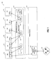
- the environment 100 for the dynamically extensible virtual switch includes, but is not necessarily limited to, one or more VMs 102 through 112, a VMM 114 and platform hardware 116. Though six VMs are shown in Figure 1 , it is understood that any number of VMs may be present in environment 100. Each of these components is described next in more detail.
- VMs 102 through 112 each include one or more VNICs.
- VM 102 includes VNIC 1 and VNIC 2
- VM 106 includes only VNIC 5.
- Each VNIC in Figure 1 has a unique ID. For illustration purposes only, assume that VNIC 1 has an ID of 1, VNIC 2 has an ID of 2, VNIC 3 has an ID of 3, and so forth.
- NIC virtualization is a technique for providing an abstraction of a physical NIC to the VMs. Through virtualization, the same physical NIC can be shared by multiple VMs. Each VM assumes that it owns the physical NIC. In addition, NIC virtualization allows a VM to be presented with multiple instances of the same physical NIC. For example, a system may have a single physical NIC, but a VM may see multiple VNICs, each of which interfaces with different networks inside the physical machine and/or the external network to which the physical NIC is attached. In an embodiment of the invention, VNIC 1 through 8 is an abstraction of network interface card (NIC) 128 in platform hardware 116.
- NIC network interface card
- VMM 114 includes a virtual switch 118.
- Virtual switch 118 includes a collection of routers 120, 122 and 124 and a data structure 126. Though three routers are shown in Figure 1 , it is understood that any number of routers may be present in virtual switch 118.
- Routers 120, 122 and 124 use data structure 126 to organize the connections among the VNICs in VMs 102 through 112 to form the various virtual networks, as will be described in more detail below.
- virtual switch 118 is agnostic of the virtualization model used by VMM 114 (e.g., hypervisor, host-based, hybrid, and so forth). Other types of virtualization models may be added or substituted for those described as new types of virtualization models are developed and according to the particular application for the invention.
- Platform hardware 116 includes a NIC 128.
- NIC 128 is connected to a physical network 130.
- Platform hardware 116 can be of a personal computer (PC), mainframe, handheld device, portable computer, set-top box, or any other computing system.
- Platform hardware 116 may include one or more processors and memory (not shown in Figure 1 ). Additionally, platform hardware 116 may include memory and a variety of other input/output devices (also not shown in Figure 1 ).
- the processors in platform hardware 116 can be any type of processor capable of executing software, such as hyper-threaded, SMP, multi-core, microprocessor, digital signal processor, microcontroller, or the like, or any combination thereof. Other types of processors may be added or substituted for those described as new types of processors are developed and according to the particular application for environment 100.
- the processors may include, but are not necessarily limited to, microcode, macrocode, software, programmable logic, hard coded logic, etc., for performing the execution of embodiments for methods of the present invention.
- the memory of platform hardware 116 can be any type of recordable/non-recordable media (e.g., random access memory (RAM), read only memory (ROM), magnetic disk storage media, optical storage media, flash memory devices, etc.), as well as electrical, optical, acoustical or other form of propagated signals (e.g., carrier waves, infrared signals, digital signals, etc.), any combination of the above devices, or any other type of machine medium readable by the processors.
- RAM random access memory
- ROM read only memory
- magnetic disk storage media e.g., magnetic disk storage media, optical storage media, flash memory devices, etc.
- electrical, optical, acoustical or other form of propagated signals e.g., carrier waves, infrared signals, digital signals, etc.
- Other types of recordable/non-recordable media may be added or substituted for those described as new types of recordable/non-recordable are developed and according to the particular application for the invention.
- Memory may store instructions for performing
- the platform hardware 116 comprises a computing platform, which may be capable, for example, of executing a standard operating system (OS) or a virtual machine monitor (VMM), such as a VMM 114.
- VMM 114 though typically implemented in software, may emulate and export a bare machine interface to higher level software.
- Such higher level software may comprise a standard or real-time OS, may be a highly stripped down operating environment with limited operating system functionality, or may not include traditional OS facilities.
- VMM 114 may be run within, or on top of, another VMM.
- VMMs and their typical features and functionality are well known by those skilled in the art and may be implemented, for example, in software, firmware, hardware or by a combination of various techniques.
- each router in virtual switch 118 represents a virtual network.
- router 120, VNIC 2 in VM 102 and VNIC 3 in VM 104 represent one virtual network
- router 122, VNIC 4 in VM 104, VNIC 5 in VM 106 and VNIC 6 in VM 108 represent a second virtual network
- router 124, VNIC 7 in VM 110 and VNIC 8 in VM 112 represent a third virtual network.
- VNIC 1 in VM 102 is the only VNIC shown in Figure 1 that is connected to physical network 130 (via NIC 128). Though four virtual networks are shown in Figure 1 , it is understood that any number of virtual networks may be present in environment 100.
- Virtual switch data structure 126 is further described next with reference to Figure 2 .
- routers 120, 122 and 124 use data structure 126 to organize the connections among the VNICs in VMs 102 through 112 to form the various virtual networks in environment 100.
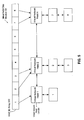
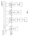
- Data structure 126 includes a VNIC ID array 202 and a virtual network head list 204. Each of these is described in more detail next.
- each VNIC in Figure 1 has a unique ID.
- VNIC 1 has an ID of 1
- VNIC 2 has an ID of 2
- VNIC 3 has an ID of 3, and so forth.
- Each unique VNIC ID serves as an index into the elements of VNIC ID array 202.
- the elements of VNIC ID array 202 contain pointers to the virtual network heads and the actual VNIC data structures (not shown in Figure 2 ).
- Each virtual network head contains a pointer to a doubly linked list of VNIC nodes.
- Each VNIC node contains the ID of a VNIC (i.e., index into the elements of VNIC ID array 202).
- VNIC 1 in VM 102 is the only VNIC that is connected to physical network 130 (via VNIC 128).
- This virtual network is illustrated in Figure 2 via element 1 in VNIC ID array 202 that contains a pointer to virtual network head 1 (of virtual network head list 204), and via virtual network head 1 that contains a pointer to a doubly linked list of VNIC nodes that contains the ID of 1 (representing VNIC 1).
- router 120, VNIC 2 in VM 102 and VNIC 3 in VM 104 create another virtual network.
- This virtual network is illustrated in Figure 2 via the elements 2 and 3 in VNIC ID array 202 that each contain a pointer to virtual network head 2, and via virtual network head 2 that contains a pointer to a doubly linked list of VNIC nodes that contains the IDs of 2 and 3 (representing VNIC 2 and VNIC 3).
- a similar arrangement is shown in Figure 2 for the other virtual networks of Figure 1 .
- virtual switch data structure 12 6 is used to dynamically perform operations on the virtual networks without restarting VM 102 through 112 and/or VMM 114. These operations include, but are not necessarily limited to, (1) creating a new virtual network; (2) deleting an existing virtual network; (3) adding a VNIC to a particular virtual network; and (4) deleting a VNIC from a particular virtual network. Embodiments of these operations are described next with reference to Figures 3-8 .
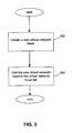
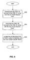
- Figure 3 is a flow diagram of one embodiment of a process for creating a new virtual network. Referring to Figure 3 , the process begins at processing block 302 where a new virtual network head is created. At processing block 304, the newly created virtual network head is added to virtual network head list 204. The process of Figure 3 ends at this point.
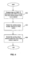
- FIG 4 is a flow diagram of one embodiment of a process for deleting an existing virtual network. For illustration purposes only, assume that virtual network 3 is to be deleted from virtual switch data structure 126 of Figure 2 . This illustration is shown in Figure 5 .
- the process begins at processing block 402 where all VNIC ID elements in VNIC ID array 202 are disassociated from the virtual network head to be deleted. In our illustration, this involves deleting the pointers from elements 4, 5 and 6 of VNIC ID array 202 (as shown in Figure 5 ).
- the corresponding doubly linked list of VNIC nodes of the virtual network head to be deleted is deleted. In our illustration, this involves deleting the doubly linked list of VNIC nodes from virtual network head 3 (as shown in Figure 5 ).
- the virtual network head is deleted from virtual network head list 204.
- this involves deleting virtual network head 3 from virtual network head list 204 (as shown in Figure 5 ).
- the process in Figure 4 ends at this point.
- FIG 6 is a flow diagram of one embodiment of a process for adding a VNIC to a particular virtual network.
- VNIC 4 (element 4 in VNIC ID array 202) is to be added to virtual network 2 of Figure 2 . This illustration is shown in Figure 7 .
- the process begins at processing block 602 where the VNIC ID element in VNIC ID array 202 is disassociated from its old virtual network head.
- element 4 is currently associated with virtual network head 3.
- the pointer from element 4 to the virtual network head 3 is deleted (as shown in Figure 7 ).
- VNIC ID element in VNIC ID array 202 is associated from its new virtual network head.
- a pointer is created from element 4 to virtual network head 2 (as shown in Figure 7 ).
- the doubly linked lists of VNIC nodes for both the old and new virtual network heads are updated.
- the VNIC 4 node is deleted from virtual network head 3's doubly linked list and added to virtual network head 2's doubly linked list (as shown in Figure 7 ).
- the process in Figure 6 ends at this point.
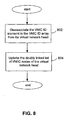
- FIG 8 is a flow diagram of one embodiment of a process for deleting a VNIC from a particular virtual network. Referring to Figure 8 , the process begins at processing block 802 where the VNIC ID element in VNIC ID array 202 is disassociated from its virtual network head.
- the doubly linked list of VNIC nodes of the virtual network head is updated to remove the VNIC node corresponding to the deleted VNIC.
- the process in Figure 8 ends at this point.
- a virtual switch may be utilized to provide a switching function for routing information or data frames between the plurality of virtual networks.
- Existing virtual switches typically identify the source VNIC node of a data frame by the MAC address of the VNIC from which the data frame was sent or by the MAC address stored in the data frame itself. Any malicious software (e.g., guest OS running in a VM) can spoof the MAC address and thus cause the receiving node of the data frame to believe it came from a different source VNIC node than the actual source VNIC node from which it came. Spoofing of MAC addresses compromises the integrity of the virtual networks.
- virtual switch 118 overcomes the situation where malicious software may spoof the MAC address by identifying the source VNIC of a data frame by its unique VNIC ID and not by the MAC address. By assigning and using VNIC IDs not visible to the processes running in the VMs, virtual switch 118 ensures that only malicious software that routes data frames based only on MAC addresses can compromise the integrity of the virtual networks.
- FIG. 9 is a flow diagram of one embodiment of a process for a data frame routing scheme that avoids the possibility of spoofing.
- the process begins at processing block 902 where virtual switch 118 identifies the source VNIC node of the data frame by its unique ID.
- virtual switch 118 utilizes the VNIC ID to index into VNIC ID array 202 to retrieve the pointer to the virtual network head to which the source VNIC node belongs.
- virtual switch 118 forwards the data frame to every VNIC node in the doubly linked list of VNIC nodes expect for the source VNIC node.
- the process of Figure 9 ends at this point.
Description
- A single physical platform may be segregated into a plurality of virtual networks. Here, the physical platform incorporates at least one virtual machine monitor (VMM). A conventional VMM typically runs on a computer and presents to other software the abstraction of one or more virtual machines (VMs). Each VM may function as a self-contained platform, running its own "guest operating system" (i.e., an operating system (OS) hosted by the VMM) and other software, collectively referred to as guest software.
- Processes running within a VM are provided with an abstraction of some hardware resources and may be unaware of other VMs within the system. Every VM assumes that it has full control over the hardware resources allocated to it. The VMM is an entity that is responsible for appropriately managing and arbitrating system resources among the VMs including, but not limited to, processors, input/out (I/O) devices and memory.
- Network interface card (NIC) virtualization is a technique for providing an abstraction of a physical NIC(s) to the VMs. Through virtualization, the same physical NIC(s) can be shared by multiple VMs. In addition, NIC virtualization allows a VM to be presented with multiple instances of the same physical NIC. For example, a system may have a single physical NIC, but a VM may see multiple virtual NICs (VNICs), each of which interfaces with different networks inside the physical platform and/or the external network to which the physical NIC is attached. In fact, the actual physical NIC does not even have to be present in order to enable inter-VM communication within a system. The VNIC that is presented to a VM may be completely different than the actual physical NIC, thereby making it possible to expose features to the VM that may not exist in the actual physical hardware.
- There is a limit on the total number of virtual networks and the maximum number of VMs per virtual network in the single physical platform. In addition, virtual networks cannot be reconfigured at run time of the VMM because it involves moving one or more VMs from one virtual network to another, which requires a restart of the affected VMs and the entire VMM.
- A virtual switch may be utilized to provide a switching function for routing information or data frames between the plurality of virtual networks. The virtual switch typically identifies the source VNIC node of a data frame by the MAC address of the VNIC from which the data frame was sent or by the MAC address stored in the data frame itself. Any malicious software (e.g., guest OS running in a VM) can spoof the MAC address and thus cause the receiving node of the data frame to believe it came from a different source VNIC node than the actual source VNIC node from which it came. Spoofing of MAC addresses comprises the integrity of the virtual networks.
GB 2389023-A
WO 0167694
Aspects of the present invention are set out in the appended independent claims. - The invention may be best understood by referring to the following description and accompanying drawings that are used to illustrate embodiments of the invention. In the drawings:
-
Figure 1 illustrates one embodiment of a virtual machine environment, in which some embodiments of the present invention may operate; -
Figure 2 illustrates a virtual switch data structure according to one embodiment of the present invention; -
Figure 3 a flow diagram of one embodiment of a process for creating a new virtual network; -
Figure 4 is a flow diagram of one embodiment of a process for deleting an existing virtual network; -
Figure 5 illustrates the operation of deleting an existing virtual network according to an embodiment of the invention; -
Figure 6 is a flow diagram of one embodiment of a process for adding a VNIC to a particular virtual network; -
Figure 7 illustrates the operation of adding a VNIC to a particular virtual network; -
Figure 8 is a flow diagram of one embodiment of a process for deleting a VNIC from a particular virtual network; and -
Figure 9 is a flow diagram of one embodiment of a process for a data frame routing scheme that avoids the possibility of spoofing. - An apparatus and method for a dynamically extensible virtual switch are described. The virtual switch of the present invention provides the ability to create, delete or reconfigure virtual networks at run time without the need to restart any VM or the VMM. In addition, the virtual switch imposes no fixed limits on the number of VMs that can be connected to any virtual network. The virtual switch also imposes no limit on the total number of virtual networks. Additionally, the virtual switch ensures that no malicious software can compromise the isolation of the virtual networks configured by the VMM administrator. In the following description, for purposes of explanation, numerous specific details are set forth. It will be apparent, however, to one skilled in the art that embodiments of the invention can be practiced without these specific details.
- Embodiments of the present invention may be implemented in software, firmware, hardware, or by any combination of various techniques. For example, in some embodiments, the present invention may be provided as a computer program product or software which may include a machine or computer-readable medium having stored thereon instructions which may be used to program a computer (or other electronic devices) to perform a process according to the present invention. In other embodiments, steps of the present invention might be performed by specific hardware components that contain hardwired logic for performing the steps, or by any combination of programmed computer components and hardware components.
- Thus, a machine-readable medium may include any mechanism for storing or transmitting information in a form readable by a machine (e.g., a computer). These mechanisms include, but are not limited to, floppy diskettes, optical disks, Compact Disc Read-Only Memory (CD-ROMs), magneto-optical disks, Read-Only Memory (ROMs), Random Access Memory (RAM), Erasable Programmable Read-Only Memory (EPROM), Electrically Erasable Programmable Read-Only Memory (EEPROM), magnetic or optical cards, flash memory, a transmission over the Internet, electrical, optical, acoustical or other forms of propagated signals (e.g., carrier waves, infrared signals, digital signals, etc.) or the like. Other types of mechanisms may be added or substituted for those described as new types of mechanisms are developed and according to the particular application for the invention.
- Some portions of the detailed descriptions that follow are presented in terms of algorithms and symbolic representations of operations on data bits within a computer system's registers or memory. These algorithmic descriptions and representations are the means used by those skilled in the data processing arts to convey the substance of their work to others skilled in the art most effectively. An algorithm is here, and generally, conceived to be a self-consistent sequence of operations leading to a desired result. The operations are those requiring physical manipulations of physical quantities. Usually, although not necessarily, these quantities take the form of electrical or magnetic signals capable of being stored, transferred, combined, compared, and otherwise manipulated. It has proven convenient at times, principally for reasons of common usage, to refer to these signals as bits, values, elements, symbols, characters, terms, numbers, or the like.
- It should be borne in mind, however, that all of these and similar terms are to be associated with the appropriate physical quantities and are merely convenient labels applied to these quantities. Unless specifically stated otherwise as apparent from the following discussions, it is appreciated that discussions utilizing terms such as "processing" or "computing" or "calculating" or "determining" or the like, may refer to the action and processes of a computer system, or a similar electronic computing device, that manipulates and transforms data represented as physical (electronic) quantities within the computer system's registers and memories into other data similarly represented as physical quantities within the computer system memories or registers or other such information storage, transmission or display devices.
- Reference throughout this specification to "one embodiment" or "an embodiment" means that a particular feature, structure, or characteristic described in connection with the embodiment is included in at least one embodiment of the invention. Thus, the appearances of the phrases "in one embodiment" or "in an embodiment" in various places throughout this specification are not necessarily all referring to the same embodiment. Furthermore, the particular features, structures, or characteristics may be combined in any suitable manner in one or more embodiments.
- In the following detailed description of the embodiments, reference is made to the accompanying drawings that show, by way of illustration, specific embodiments in which the invention may be practiced. In the drawings, like numerals describe substantially similar components throughout the several views. These embodiments are described in sufficient detail to enable those skilled in the art to practice the invention. Other embodiments may be utilized and structural, logical, and electrical changes may be made without departing from the scope of the present invention.
-
Figure 1 illustrates one embodiment of an environment for the dynamically extensible virtual switch, in which some embodiments of the present invention may operate. The specific components shown inFigure 1 represent one example of a configuration that may be suitable for the invention and is not meant to limit the invention. - Referring to
Figure 1 , theenvironment 100 for the dynamically extensible virtual switch includes, but is not necessarily limited to, one ormore VMs 102 through 112, aVMM 114 andplatform hardware 116. Though six VMs are shown inFigure 1 , it is understood that any number of VMs may be present inenvironment 100. Each of these components is described next in more detail. -
VMs 102 through 112 each include one or more VNICs. For example,VM 102 includesVNIC 1 andVNIC 2, whereas VM 106 includes only VNIC 5. Each VNIC inFigure 1 has a unique ID. For illustration purposes only, assume thatVNIC 1 has an ID of 1,VNIC 2 has an ID of 2,VNIC 3 has an ID of 3, and so forth. - NIC virtualization is a technique for providing an abstraction of a physical NIC to the VMs. Through virtualization, the same physical NIC can be shared by multiple VMs. Each VM assumes that it owns the physical NIC. In addition, NIC virtualization allows a VM to be presented with multiple instances of the same physical NIC. For example, a system may have a single physical NIC, but a VM may see multiple VNICs, each of which interfaces with different networks inside the physical machine and/or the external network to which the physical NIC is attached. In an embodiment of the invention,
VNIC 1 through 8 is an abstraction of network interface card (NIC) 128 inplatform hardware 116. -
VMM 114 includes avirtual switch 118.Virtual switch 118 includes a collection ofrouters data structure 126. Though three routers are shown inFigure 1 , it is understood that any number of routers may be present invirtual switch 118.Routers use data structure 126 to organize the connections among the VNICs inVMs 102 through 112 to form the various virtual networks, as will be described in more detail below. In an embodiment of the invention,virtual switch 118 is agnostic of the virtualization model used by VMM 114 (e.g., hypervisor, host-based, hybrid, and so forth). Other types of virtualization models may be added or substituted for those described as new types of virtualization models are developed and according to the particular application for the invention. -
Platform hardware 116 includes aNIC 128.NIC 128 is connected to a physical network 130.Platform hardware 116 can be of a personal computer (PC), mainframe, handheld device, portable computer, set-top box, or any other computing system.Platform hardware 116 may include one or more processors and memory (not shown inFigure 1 ). Additionally,platform hardware 116 may include memory and a variety of other input/output devices (also not shown inFigure 1 ). - The processors in
platform hardware 116 can be any type of processor capable of executing software, such as hyper-threaded, SMP, multi-core, microprocessor, digital signal processor, microcontroller, or the like, or any combination thereof. Other types of processors may be added or substituted for those described as new types of processors are developed and according to the particular application forenvironment 100. The processors may include, but are not necessarily limited to, microcode, macrocode, software, programmable logic, hard coded logic, etc., for performing the execution of embodiments for methods of the present invention. - The memory of
platform hardware 116 can be any type of recordable/non-recordable media (e.g., random access memory (RAM), read only memory (ROM), magnetic disk storage media, optical storage media, flash memory devices, etc.), as well as electrical, optical, acoustical or other form of propagated signals (e.g., carrier waves, infrared signals, digital signals, etc.), any combination of the above devices, or any other type of machine medium readable by the processors. Other types of recordable/non-recordable media may be added or substituted for those described as new types of recordable/non-recordable are developed and according to the particular application for the invention. Memory may store instructions for performing the execution of method embodiments of the present invention. - In
environment 100, theplatform hardware 116 comprises a computing platform, which may be capable, for example, of executing a standard operating system (OS) or a virtual machine monitor (VMM), such as aVMM 114.VMM 114, though typically implemented in software, may emulate and export a bare machine interface to higher level software. Such higher level software may comprise a standard or real-time OS, may be a highly stripped down operating environment with limited operating system functionality, or may not include traditional OS facilities. Alternatively, for example,VMM 114 may be run within, or on top of, another VMM. VMMs and their typical features and functionality are well known by those skilled in the art and may be implemented, for example, in software, firmware, hardware or by a combination of various techniques. - In an embodiment of the invention, each router in
virtual switch 118, along with its associated VNICs, represent a virtual network. Thus,router 120,VNIC 2 inVM 102 andVNIC 3 inVM 104 represent one virtual network;router 122,VNIC 4 inVM 104,VNIC 5 in VM 106 andVNIC 6 inVM 108 represent a second virtual network; androuter 124,VNIC 7 in VM 110 andVNIC 8 in VM 112 represent a third virtual network.VNIC 1 inVM 102 is the only VNIC shown inFigure 1 that is connected to physical network 130 (via NIC 128). Though four virtual networks are shown inFigure 1 , it is understood that any number of virtual networks may be present inenvironment 100. - Virtual
switch data structure 126 is further described next with reference toFigure 2 . As described above,routers use data structure 126 to organize the connections among the VNICs inVMs 102 through 112 to form the various virtual networks inenvironment 100.Data structure 126 includes aVNIC ID array 202 and a virtualnetwork head list 204. Each of these is described in more detail next. - In an embodiment of the invention, each VNIC in
Figure 1 has a unique ID. For illustration purposes only, assume thatVNIC 1 has an ID of 1,VNIC 2 has an ID of 2,VNIC 3 has an ID of 3, and so forth. Each unique VNIC ID serves as an index into the elements ofVNIC ID array 202. The elements ofVNIC ID array 202 contain pointers to the virtual network heads and the actual VNIC data structures (not shown inFigure 2 ). Each virtual network head contains a pointer to a doubly linked list of VNIC nodes. Each VNIC node contains the ID of a VNIC (i.e., index into the elements of VNIC ID array 202). - In an embodiment of the invention, and as described above with reference to
Figure 1 ,VNIC 1 inVM 102 is the only VNIC that is connected to physical network 130 (via VNIC 128). This virtual network is illustrated inFigure 2 viaelement 1 inVNIC ID array 202 that contains a pointer to virtual network head 1 (of virtual network head list 204), and viavirtual network head 1 that contains a pointer to a doubly linked list of VNIC nodes that contains the ID of 1 (representing VNIC 1). - Also as described above with reference to
Figure 1 ,router 120,VNIC 2 inVM 102 andVNIC 3 inVM 104 create another virtual network. This virtual network is illustrated inFigure 2 via theelements VNIC ID array 202 that each contain a pointer tovirtual network head 2, and viavirtual network head 2 that contains a pointer to a doubly linked list of VNIC nodes that contains the IDs of 2 and 3 (representingVNIC 2 and VNIC 3). A similar arrangement is shown inFigure 2 for the other virtual networks ofFigure 1 . - In an embodiment of the invention, virtual switch data structure 12 6 is used to dynamically perform operations on the virtual networks without restarting
VM 102 through 112 and/orVMM 114. These operations include, but are not necessarily limited to, (1) creating a new virtual network; (2) deleting an existing virtual network; (3) adding a VNIC to a particular virtual network; and (4) deleting a VNIC from a particular virtual network. Embodiments of these operations are described next with reference toFigures 3-8 . -
Figure 3 is a flow diagram of one embodiment of a process for creating a new virtual network. Referring toFigure 3 , the process begins atprocessing block 302 where a new virtual network head is created. Atprocessing block 304, the newly created virtual network head is added to virtualnetwork head list 204. The process ofFigure 3 ends at this point. -
Figure 4 is a flow diagram of one embodiment of a process for deleting an existing virtual network. For illustration purposes only, assume thatvirtual network 3 is to be deleted from virtualswitch data structure 126 ofFigure 2 . This illustration is shown inFigure 5 . - Referring to
Figure 4 , the process begins atprocessing block 402 where all VNIC ID elements inVNIC ID array 202 are disassociated from the virtual network head to be deleted. In our illustration, this involves deleting the pointers fromelements Figure 5 ). - At
processing block 404, the corresponding doubly linked list of VNIC nodes of the virtual network head to be deleted is deleted. In our illustration, this involves deleting the doubly linked list of VNIC nodes from virtual network head 3 (as shown inFigure 5 ). - At
processing block 406, the virtual network head is deleted from virtualnetwork head list 204. In our illustration, this involves deletingvirtual network head 3 from virtual network head list 204 (as shown inFigure 5 ). The process inFigure 4 ends at this point. -
Figure 6 is a flow diagram of one embodiment of a process for adding a VNIC to a particular virtual network. For illustration purposes only, assume that VNIC 4 (element 4 in VNIC ID array 202) is to be added tovirtual network 2 ofFigure 2 . This illustration is shown inFigure 7 . - Referring to
Figure 6 , the process begins atprocessing block 602 where the VNIC ID element inVNIC ID array 202 is disassociated from its old virtual network head. In our illustration,element 4 is currently associated withvirtual network head 3. Thus, the pointer fromelement 4 to thevirtual network head 3 is deleted (as shown inFigure 7 ). - In
processing block 604, the VNIC ID element inVNIC ID array 202 is associated from its new virtual network head. In our illustration, a pointer is created fromelement 4 to virtual network head 2 (as shown inFigure 7 ). - In
processing block 606, the doubly linked lists of VNIC nodes for both the old and new virtual network heads are updated. In our illustration, theVNIC 4 node is deleted fromvirtual network head 3's doubly linked list and added tovirtual network head 2's doubly linked list (as shown inFigure 7 ). The process inFigure 6 ends at this point. -
Figure 8 is a flow diagram of one embodiment of a process for deleting a VNIC from a particular virtual network. Referring toFigure 8 , the process begins atprocessing block 802 where the VNIC ID element inVNIC ID array 202 is disassociated from its virtual network head. - At
processing block 804, the doubly linked list of VNIC nodes of the virtual network head is updated to remove the VNIC node corresponding to the deleted VNIC. The process inFigure 8 ends at this point. - As described above, a virtual switch may be utilized to provide a switching function for routing information or data frames between the plurality of virtual networks. Existing virtual switches typically identify the source VNIC node of a data frame by the MAC address of the VNIC from which the data frame was sent or by the MAC address stored in the data frame itself. Any malicious software (e.g., guest OS running in a VM) can spoof the MAC address and thus cause the receiving node of the data frame to believe it came from a different source VNIC node than the actual source VNIC node from which it came. Spoofing of MAC addresses compromises the integrity of the virtual networks.
- In an embodiment of the present invention,
virtual switch 118 overcomes the situation where malicious software may spoof the MAC address by identifying the source VNIC of a data frame by its unique VNIC ID and not by the MAC address. By assigning and using VNIC IDs not visible to the processes running in the VMs,virtual switch 118 ensures that only malicious software that routes data frames based only on MAC addresses can compromise the integrity of the virtual networks. -
Figure 9 is a flow diagram of one embodiment of a process for a data frame routing scheme that avoids the possibility of spoofing. Referring toFigure 9 , the process begins atprocessing block 902 wherevirtual switch 118 identifies the source VNIC node of the data frame by its unique ID. - At
processing block 904,virtual switch 118 utilizes the VNIC ID to index intoVNIC ID array 202 to retrieve the pointer to the virtual network head to which the source VNIC node belongs. - At
processing block 906,virtual switch 118 forwards the data frame to every VNIC node in the doubly linked list of VNIC nodes expect for the source VNIC node. The process ofFigure 9 ends at this point. - An apparatus and method for a dynamically extensible virtual switch have been described. It is to be understood that the above description is intended to be illustrative, and not restrictive. Many other embodiments will be apparent to those of skill in the art upon reading and understanding the above description. The scope of the invention should, therefore, be determined with reference to the appended claims.
Claims (15)
- An apparatus, comprising:at least one router (120,122,124); anda virtual switch including a data structure (126), wherein the at least one router utilizes the data structure to organize a connection between one or more virtual network interface cards, VNICs, cach located in one of a plurality of virtual machines, VMs, to provide a physical abstraction of a physical NIC to a VM to form a virtual network wherein the VMs provide an abstraction of a hardware resource.
- The apparatus of claim 1, wherein the one or more VNICs each has a unique identifier.
- The apparatus of claim 1, wherein the data structure comprises:a collection of elements indexed by the unique identifiers of the one or more VNICs; anda virtual network head listing (204), wherein each element in the collection of elements is associated with a virtual network head in the virtual network head listing, wherein each of the virtual network heads in the virtual network head listing is associated with a VNIC node listing, and wherein each VNIC node in the VNIC node listing contains one of the unique identifiers of the one or more VNICs.
- The apparatus of claim 3, wherein the collection of elements is an array.
- The apparatus of claim 3, wherein the VNIC node listing is a doubly linked list of VNIC nodes.
- A method comprising:forming a virtual network via at least one router (120,122,124) and a virtual switch (118) including a data structure, wherein the at least one router utilizes the data structure to organize a connection between one or more virtual network interface cards, VNICs, each located in one of a plurality of virtual machines, VMs to provide a physical abstraction of a physical NIC to a VM, wherein the VMs provide an abstraction of a hardware resource.
- The method of claim 6, wherein the one or more VNICs each has a unique identifier.
- The method of claim 7, wherein the data structure comprises a collection of elements indexed by the unique identifiers of the one or more VNICs and a virtual network head listing, wherein each element in the collection of elements is associated with a virtual network head in the virtual network head listing, wherein each of the virtual network heads in the virtual network head listing is associated with a VNIC node listing, and wherein each VNIC node in the VNIC node listing contains one of the unique identifiers of the one or more VNICs.
- The method of claim 8, further comprising creating a new virtual network, wherein creating a new virtual network comprises:creating a new virtual network head; andadding the new virtual network head to the virtual network head listing.
- A method comprising:forming at least two virtual networks via at least two routers (120-124) and a virtual switch (118) including a data structure (126), wherein the at least two routers utilizes the data structure to organize a connection between one or more virtual network interface cards, VNICs, each located in one of a plurality of virtual machines, VMs to provide a physical abstraction of a physical NIC to a VM, wherein the VMs provide an abstraction of a hardware resource.
- The method of claim 10, wherein the one or more VNICs each has a unique identifier, wherein the data structure comprises a collection of elements indexed by the unique identifiers of the one or more VNICs and a virtual network head listing, wherein each element in the collection of elements is associated with a virtual network head in the virtual network head listing, wherein each of the virtual network heads in the virtual network head listing is associated with a VNIC node listing, and wherein each VNIC node in the VNIC node listing contains one of the unique identifiers of the one or more VNICs.
- The method of claim 11, further comprising deleting one of the at least two virtual networks, wherein deleting the virtual network comprises:determining the virtual network head in the virtual network head listing that represents the virtual network to be deleted;disassociating (402) each element in the collection of elements associated with the determined virtual network head;disassociating the VNIC node listing associated with the determined virtual network head; anddeleting (404) the determined virtual network head from the virtual network head listing.
- The method of claim 11, further comprising deleting a VN IC from one of the at least two virtual networks, wherein deleting the VNIC comprises:determining the virtual network head in the virtual network head listing that represents the virtual network associated with the VNIC to be deleted;disassociating the clement in the collection of elements indexed by the unique identifier of the VNIC to be deleted from the determined virtual network head; anddeleting the VNIC node in the VNIC node listing associated with the determined virtual network head that contains the unique identifier of the VNIC to be deleted.
- The method of claim 11, further comprising adding a VNIC to one of the at least two virtual networks, wherein adding the VNIC comprises:determining the virtual network head in the virtual network head listing that represents the virtual network associated with the VNIC to be added;associating the element in the collection of elements indexed by the unique identifier of the VNIC to be added to the determined virtual network head; andadding a VNIC node in the VNIC node listing associated with the determined virtual network head that contains the unique identifier of the VNIC to be added.
- A machine-readable medium containing instructions which, when executed by a processing system, cause the processing system to perform all of the steps of a method as claimed in any one of claims 6 to 14.
Applications Claiming Priority (2)
| Application Number | Priority Date | Filing Date | Title |
|---|---|---|---|
| US10/779,083 US8838743B2 (en) | 2004-02-13 | 2004-02-13 | Apparatus and method for a dynamically extensible virtual switch |
| PCT/US2005/001602 WO2005083946A1 (en) | 2004-02-13 | 2005-01-21 | Apparatus and method for a dynamically extensible virtual switch |
Publications (2)
| Publication Number | Publication Date |
|---|---|
| EP1716671A1 EP1716671A1 (en) | 2006-11-02 |
| EP1716671B1 true EP1716671B1 (en) | 2013-08-14 |
Family
ID=34838309
Family Applications (1)
| Application Number | Title | Priority Date | Filing Date |
|---|---|---|---|
| EP05711612.1A Active EP1716671B1 (en) | 2004-02-13 | 2005-01-21 | Apparatus and method for a dynamically extensible virtual switch |
Country Status (5)
| Country | Link |
|---|---|
| US (1) | US8838743B2 (en) |
| EP (1) | EP1716671B1 (en) |
| JP (2) | JP4912893B2 (en) |
| CN (2) | CN1943179B (en) |
| WO (1) | WO2005083946A1 (en) |
Families Citing this family (118)
| Publication number | Priority date | Publication date | Assignee | Title |
|---|---|---|---|---|
| US8838743B2 (en) | 2004-02-13 | 2014-09-16 | Intel Corporation | Apparatus and method for a dynamically extensible virtual switch |
| US9264384B1 (en) * | 2004-07-22 | 2016-02-16 | Oracle International Corporation | Resource virtualization mechanism including virtual host bus adapters |
| US7515589B2 (en) * | 2004-08-27 | 2009-04-07 | International Business Machines Corporation | Method and apparatus for providing network virtualization |
| US7865908B2 (en) * | 2005-03-11 | 2011-01-04 | Microsoft Corporation | VM network traffic monitoring and filtering on the host |
| US7992144B1 (en) * | 2005-04-04 | 2011-08-02 | Oracle America, Inc. | Method and apparatus for separating and isolating control of processing entities in a network interface |
| US7561531B2 (en) * | 2005-04-19 | 2009-07-14 | Intel Corporation | Apparatus and method having a virtual bridge to route data frames |
| US7675920B1 (en) * | 2005-04-22 | 2010-03-09 | Sun Microsystems, Inc. | Method and apparatus for processing network traffic associated with specific protocols |
| US7607168B1 (en) * | 2005-04-22 | 2009-10-20 | Sun Microsystems, Inc. | Network interface decryption and classification technique |
| US9813283B2 (en) | 2005-08-09 | 2017-11-07 | Oracle International Corporation | Efficient data transfer between servers and remote peripherals |
| US7930443B1 (en) * | 2005-10-26 | 2011-04-19 | Juniper Networks, Inc. | Router having routing engine software instance and interface controller software instance on a single processor |
| JP4622835B2 (en) * | 2005-12-07 | 2011-02-02 | 株式会社日立製作所 | Virtual computer system and network communication method thereof |
| JP4542514B2 (en) * | 2006-02-13 | 2010-09-15 | 株式会社日立製作所 | Computer control method, program, and virtual computer system |
| US8892706B1 (en) | 2010-06-21 | 2014-11-18 | Vmware, Inc. | Private ethernet overlay networks over a shared ethernet in a virtual environment |
| US8838756B2 (en) * | 2009-07-27 | 2014-09-16 | Vmware, Inc. | Management and implementation of enclosed local networks in a virtual lab |
| US8619771B2 (en) | 2009-09-30 | 2013-12-31 | Vmware, Inc. | Private allocated networks over shared communications infrastructure |
| US8924524B2 (en) | 2009-07-27 | 2014-12-30 | Vmware, Inc. | Automated network configuration of virtual machines in a virtual lab data environment |
| US7634608B2 (en) * | 2006-06-30 | 2009-12-15 | Sun Microsystems, Inc. | Bridging network components |
| US7830882B2 (en) * | 2006-11-17 | 2010-11-09 | Intel Corporation | Switch scaling for virtualized network interface controllers |
| US20080313254A1 (en) * | 2007-06-18 | 2008-12-18 | Hilemon Christopher G | Virtual fieldbus device |
| US7945647B2 (en) * | 2007-12-10 | 2011-05-17 | Oracle America, Inc. | Method and system for creating a virtual network path |
| US7962587B2 (en) * | 2007-12-10 | 2011-06-14 | Oracle America, Inc. | Method and system for enforcing resource constraints for virtual machines across migration |
| US7984123B2 (en) * | 2007-12-10 | 2011-07-19 | Oracle America, Inc. | Method and system for reconfiguring a virtual network path |
| US8095661B2 (en) * | 2007-12-10 | 2012-01-10 | Oracle America, Inc. | Method and system for scaling applications on a blade chassis |
| US8370530B2 (en) * | 2007-12-10 | 2013-02-05 | Oracle America, Inc. | Method and system for controlling network traffic in a blade chassis |
| US8086739B2 (en) * | 2007-12-10 | 2011-12-27 | Oracle America, Inc. | Method and system for monitoring virtual wires |
| US20100325628A1 (en) * | 2008-02-25 | 2010-12-23 | Tomoyuki Haga | Information processing device |
| US7970951B2 (en) * | 2008-02-29 | 2011-06-28 | Oracle America, Inc. | Method and system for media-based data transfer |
| US7965714B2 (en) * | 2008-02-29 | 2011-06-21 | Oracle America, Inc. | Method and system for offloading network processing |
| GB2459433B (en) | 2008-03-07 | 2012-06-06 | Hewlett Packard Development Co | Distributed network connection policy management |
| GB2458157B (en) * | 2008-03-07 | 2012-04-25 | Hewlett Packard Development Co | Virtual machine liveness check |
| GB2458154B (en) * | 2008-03-07 | 2012-06-27 | Hewlett Packard Development Co | Routing across a virtual network |
| US7944923B2 (en) * | 2008-03-24 | 2011-05-17 | Oracle America, Inc. | Method and system for classifying network traffic |
| US8195774B2 (en) | 2008-05-23 | 2012-06-05 | Vmware, Inc. | Distributed virtual switch for virtualized computer systems |
| US8739179B2 (en) * | 2008-06-30 | 2014-05-27 | Oracle America Inc. | Method and system for low-overhead data transfer |
| US7941539B2 (en) * | 2008-06-30 | 2011-05-10 | Oracle America, Inc. | Method and system for creating a virtual router in a blade chassis to maintain connectivity |
| US9106540B2 (en) * | 2009-03-30 | 2015-08-11 | Amazon Technologies, Inc. | Providing logical networking functionality for managed computer networks |
| US8589919B2 (en) * | 2009-04-28 | 2013-11-19 | Cisco Technology, Inc. | Traffic forwarding for virtual machines |
| US8472443B2 (en) * | 2009-05-15 | 2013-06-25 | Cisco Technology | Port grouping for association with virtual interfaces |
| US8180877B2 (en) * | 2009-06-04 | 2012-05-15 | International Business Machines Corporation | Logically partitioned system having subpartitions with flexible network connectivity configuration |
| US9973446B2 (en) | 2009-08-20 | 2018-05-15 | Oracle International Corporation | Remote shared server peripherals over an Ethernet network for resource virtualization |
| US8639783B1 (en) | 2009-08-28 | 2014-01-28 | Cisco Technology, Inc. | Policy based configuration of interfaces in a virtual machine environment |
| CN102648455B (en) * | 2009-12-04 | 2015-11-25 | 日本电气株式会社 | Server and stream control routine |
| JP5347982B2 (en) * | 2010-01-18 | 2013-11-20 | 富士通株式会社 | Virtual network control program, virtual network control method, and management apparatus |
| JP5402688B2 (en) * | 2010-02-02 | 2014-01-29 | 日本電気株式会社 | Packet transfer system and method for avoiding packet concentration in packet transfer system |
| US20110202685A1 (en) * | 2010-02-16 | 2011-08-18 | Narayanan Subramaniam | System and Method for Communication Between an Information Handling System and Management Controller Through a Shared LOM |
| US8599854B2 (en) * | 2010-04-16 | 2013-12-03 | Cisco Technology, Inc. | Method of identifying destination in a virtual environment |
| US8477610B2 (en) * | 2010-05-31 | 2013-07-02 | Microsoft Corporation | Applying policies to schedule network bandwidth among virtual machines |
| WO2012011218A1 (en) * | 2010-07-21 | 2012-01-26 | Nec Corporation | Computer system and offloading method in computer system |
| US9906429B2 (en) | 2010-09-17 | 2018-02-27 | Oracle International Corporation | Performing partial subnet initialization in a middleware machine environment |
| US9331963B2 (en) | 2010-09-24 | 2016-05-03 | Oracle International Corporation | Wireless host I/O using virtualized I/O controllers |
| US8429276B1 (en) | 2010-10-25 | 2013-04-23 | Juniper Networks, Inc. | Dynamic resource allocation in virtual environments |
| US8634415B2 (en) | 2011-02-16 | 2014-01-21 | Oracle International Corporation | Method and system for routing network traffic for a blade server |
| US9858241B2 (en) | 2013-11-05 | 2018-01-02 | Oracle International Corporation | System and method for supporting optimized buffer utilization for packet processing in a networking device |
| US9614747B2 (en) | 2011-02-24 | 2017-04-04 | Nec Corporation | Network system, controller, and flow control method |
| US20120311182A1 (en) | 2011-06-03 | 2012-12-06 | Oracle International Corporation | System and method for supporting controlled re-routing in an infiniband (ib) network |
| US8713649B2 (en) | 2011-06-03 | 2014-04-29 | Oracle International Corporation | System and method for providing restrictions on the location of peer subnet manager (SM) instances in an infiniband (IB) network |
| CN106850878B (en) * | 2011-08-17 | 2020-07-14 | Nicira股份有限公司 | Logical L3 routing |
| US8966499B2 (en) * | 2011-09-09 | 2015-02-24 | Microsoft Technology Licensing, Llc | Virtual switch extensibility |
| WO2013147805A1 (en) * | 2012-03-29 | 2013-10-03 | Intel Corporation | Techniques for using an assigned switch identification at an input/output device |
| US9325562B2 (en) * | 2012-05-15 | 2016-04-26 | International Business Machines Corporation | Overlay tunnel information exchange protocol |
| US9262155B2 (en) | 2012-06-04 | 2016-02-16 | Oracle International Corporation | System and method for supporting in-band/side-band firmware upgrade of input/output (I/O) devices in a middleware machine environment |
| US9401963B2 (en) | 2012-06-04 | 2016-07-26 | Oracle International Corporation | System and method for supporting reliable connection (RC) based subnet administrator (SA) access in an engineered system for middleware and application execution |
| US8942237B2 (en) | 2012-06-20 | 2015-01-27 | International Business Machines Corporation | Hypervisor independent network virtualization |
| CN103514044B (en) * | 2012-06-29 | 2017-02-08 | 北京金山安全软件有限公司 | Resource optimization method, device and system of dynamic behavior analysis system |
| US9210079B2 (en) | 2012-08-14 | 2015-12-08 | Vmware, Inc. | Method and system for virtual and physical network integration |
| US9083550B2 (en) | 2012-10-29 | 2015-07-14 | Oracle International Corporation | Network virtualization over infiniband |
| JP6079218B2 (en) * | 2012-12-26 | 2017-02-15 | 日本電気株式会社 | Communication control system, communication control method, and communication control program |
| US9116727B2 (en) | 2013-01-15 | 2015-08-25 | Lenovo Enterprise Solutions (Singapore) Pte. Ltd. | Scalable network overlay virtualization using conventional virtual switches |
| JP6011401B2 (en) * | 2013-03-18 | 2016-10-19 | 富士通株式会社 | Information processing apparatus and method for generating connection information |
| US9571386B2 (en) | 2013-07-08 | 2017-02-14 | Nicira, Inc. | Hybrid packet processing |
| US9282019B2 (en) | 2013-07-12 | 2016-03-08 | Nicira, Inc. | Tracing logical network packets through physical network |
| US9344349B2 (en) | 2013-07-12 | 2016-05-17 | Nicira, Inc. | Tracing network packets by a cluster of network controllers |
| US9407580B2 (en) | 2013-07-12 | 2016-08-02 | Nicira, Inc. | Maintaining data stored with a packet |
| US9674087B2 (en) | 2013-09-15 | 2017-06-06 | Nicira, Inc. | Performing a multi-stage lookup to classify packets |
| US9602398B2 (en) | 2013-09-15 | 2017-03-21 | Nicira, Inc. | Dynamically generating flows with wildcard fields |
| US9575782B2 (en) * | 2013-10-13 | 2017-02-21 | Nicira, Inc. | ARP for logical router |
| US9489327B2 (en) | 2013-11-05 | 2016-11-08 | Oracle International Corporation | System and method for supporting an efficient packet processing model in a network environment |
| US9967199B2 (en) | 2013-12-09 | 2018-05-08 | Nicira, Inc. | Inspecting operations of a machine to detect elephant flows |
| US10193771B2 (en) | 2013-12-09 | 2019-01-29 | Nicira, Inc. | Detecting and handling elephant flows |
| US9996467B2 (en) | 2013-12-13 | 2018-06-12 | Nicira, Inc. | Dynamically adjusting the number of flows allowed in a flow table cache |
| US9569368B2 (en) | 2013-12-13 | 2017-02-14 | Nicira, Inc. | Installing and managing flows in a flow table cache |
| US9893988B2 (en) | 2014-03-27 | 2018-02-13 | Nicira, Inc. | Address resolution using multiple designated instances of a logical router |
| US9385954B2 (en) | 2014-03-31 | 2016-07-05 | Nicira, Inc. | Hashing techniques for use in a network environment |
| US10193806B2 (en) | 2014-03-31 | 2019-01-29 | Nicira, Inc. | Performing a finishing operation to improve the quality of a resulting hash |
| WO2015149253A1 (en) * | 2014-03-31 | 2015-10-08 | 华为技术有限公司 | Data center system and virtual network management method of data center |
| US9985896B2 (en) | 2014-03-31 | 2018-05-29 | Nicira, Inc. | Caching of service decisions |
| US9906494B2 (en) | 2014-03-31 | 2018-02-27 | Nicira, Inc. | Configuring interactions with a firewall service virtual machine |
| US9503427B2 (en) * | 2014-03-31 | 2016-11-22 | Nicira, Inc. | Method and apparatus for integrating a service virtual machine |
| US9742881B2 (en) | 2014-06-30 | 2017-08-22 | Nicira, Inc. | Network virtualization using just-in-time distributed capability for classification encoding |
| US9459903B2 (en) * | 2014-09-24 | 2016-10-04 | Intel Corporation | Techniques for routing service chain flow packets between virtual machines |
| US9768980B2 (en) | 2014-09-30 | 2017-09-19 | Nicira, Inc. | Virtual distributed bridging |
| US10250443B2 (en) | 2014-09-30 | 2019-04-02 | Nicira, Inc. | Using physical location to modify behavior of a distributed virtual network element |
| US11178051B2 (en) | 2014-09-30 | 2021-11-16 | Vmware, Inc. | Packet key parser for flow-based forwarding elements |
| US10511458B2 (en) | 2014-09-30 | 2019-12-17 | Nicira, Inc. | Virtual distributed bridging |
| US10020960B2 (en) | 2014-09-30 | 2018-07-10 | Nicira, Inc. | Virtual distributed bridging |
| US10469342B2 (en) | 2014-10-10 | 2019-11-05 | Nicira, Inc. | Logical network traffic analysis |
| US9923811B2 (en) | 2015-06-27 | 2018-03-20 | Nicira, Inc. | Logical routers and switches in a multi-datacenter environment |
| US10225184B2 (en) | 2015-06-30 | 2019-03-05 | Nicira, Inc. | Redirecting traffic in a virtual distributed router environment |
| US10545771B2 (en) | 2016-12-02 | 2020-01-28 | International Business Machines Corporation | Concurrent maintenance of an input/output adapter backing a virtual network interface controller |
| US10805239B2 (en) | 2017-03-07 | 2020-10-13 | Nicira, Inc. | Visualization of path between logical network endpoints |
| US10681000B2 (en) | 2017-06-30 | 2020-06-09 | Nicira, Inc. | Assignment of unique physical network addresses for logical network addresses |
| US10637800B2 (en) | 2017-06-30 | 2020-04-28 | Nicira, Inc | Replacement of logical network addresses with physical network addresses |
| US11469953B2 (en) | 2017-09-27 | 2022-10-11 | Intel Corporation | Interworking of legacy appliances in virtualized networks |
| US10608887B2 (en) | 2017-10-06 | 2020-03-31 | Nicira, Inc. | Using packet tracing tool to automatically execute packet capture operations |
| WO2019079960A1 (en) * | 2017-10-24 | 2019-05-02 | Intel Corporation | Hardware assisted virtual switch |
| US10374827B2 (en) | 2017-11-14 | 2019-08-06 | Nicira, Inc. | Identifier that maps to different networks at different datacenters |
| US10511459B2 (en) | 2017-11-14 | 2019-12-17 | Nicira, Inc. | Selection of managed forwarding element for bridge spanning multiple datacenters |
| CN108965169B (en) * | 2018-07-12 | 2020-09-25 | 联想(北京)有限公司 | Message transmission method, network card controller, network card and electronic equipment |
| US11283699B2 (en) | 2020-01-17 | 2022-03-22 | Vmware, Inc. | Practical overlay network latency measurement in datacenter |
| US11683233B2 (en) | 2020-04-06 | 2023-06-20 | Vmware, Inc. | Provision of logical network data from global manager to local managers |
| US11196628B1 (en) | 2020-07-29 | 2021-12-07 | Vmware, Inc. | Monitoring container clusters |
| US11558426B2 (en) | 2020-07-29 | 2023-01-17 | Vmware, Inc. | Connection tracking for container cluster |
| US11570090B2 (en) | 2020-07-29 | 2023-01-31 | Vmware, Inc. | Flow tracing operation in container cluster |
| US11736436B2 (en) | 2020-12-31 | 2023-08-22 | Vmware, Inc. | Identifying routes with indirect addressing in a datacenter |
| US11336533B1 (en) | 2021-01-08 | 2022-05-17 | Vmware, Inc. | Network visualization of correlations between logical elements and associated physical elements |
| US11687210B2 (en) | 2021-07-05 | 2023-06-27 | Vmware, Inc. | Criteria-based expansion of group nodes in a network topology visualization |
| US11711278B2 (en) | 2021-07-24 | 2023-07-25 | Vmware, Inc. | Visualization of flow trace operation across multiple sites |
| US11855862B2 (en) | 2021-09-17 | 2023-12-26 | Vmware, Inc. | Tagging packets for monitoring and analysis |
Family Cites Families (23)
| Publication number | Priority date | Publication date | Assignee | Title |
|---|---|---|---|---|
| EP0167694A1 (en) | 1984-06-08 | 1986-01-15 | Alessandro Marinucci | Apparatus for the interception and storage of the eolian energy and for the utilization thereof |
| US5822523A (en) * | 1996-02-01 | 1998-10-13 | Mpath Interactive, Inc. | Server-group messaging system for interactive applications |
| US6144661A (en) * | 1996-02-05 | 2000-11-07 | Kabushiki Kaisha Toshiba | Network node apparatus and virtual connection control method for providing various service attributes in multicast communication |
| WO2001067694A1 (en) | 2000-03-03 | 2001-09-13 | Celox Networks, Inc. | Broadband mid-network server |
| DE10123821A1 (en) * | 2000-06-02 | 2001-12-20 | Ibm | Switched Ethernet network has a method for assigning priorities to user groups so that a quality of service guarantee can be provided by ensuring that packets for one or more groups are given priority over other groups |
| JP3447674B2 (en) | 2000-07-11 | 2003-09-16 | エヌイーシーコンピュータテクノ株式会社 | Automatic route selection method and method |
| US7242665B2 (en) * | 2001-01-25 | 2007-07-10 | Ericsson Ab | Network device virtual interface |
| US7366784B2 (en) | 2001-11-27 | 2008-04-29 | Hitachi, Ltd. | System and method for providing and using a VLAN-aware storage device |
| JP3926158B2 (en) | 2002-01-23 | 2007-06-06 | 日本電気通信システム株式会社 | Traffic load balancing method and method |
| US6963932B2 (en) * | 2002-01-30 | 2005-11-08 | Intel Corporation | Intermediate driver having a fail-over function for a virtual network interface card in a system utilizing Infiniband architecture |
| US7801155B2 (en) * | 2002-03-01 | 2010-09-21 | Verizon Business Global Llc | Resource allocation in virtual routers |
| US7213246B1 (en) * | 2002-03-28 | 2007-05-01 | Veritas Operating Corporation | Failing over a virtual machine |
| GB2389023B (en) | 2002-05-20 | 2004-04-28 | Sun Microsystems Inc | Computer system, method and network |
| US7111303B2 (en) * | 2002-07-16 | 2006-09-19 | International Business Machines Corporation | Virtual machine operating system LAN |
| US6907039B2 (en) * | 2002-07-20 | 2005-06-14 | Redback Networks Inc. | Method and apparatus for routing and forwarding between virtual routers within a single network element |
| US7356818B2 (en) * | 2003-06-24 | 2008-04-08 | International Business Machines Corporation | Virtual machine communicating to external device without going through other virtual machines by using a list of IP addresses managed only by a single virtual machine monitor |
| US20050216380A1 (en) * | 2003-08-30 | 2005-09-29 | Morris Mary B | Data warehouse for management and analysis of telecommunications access services |
| US7934020B1 (en) * | 2003-09-19 | 2011-04-26 | Vmware, Inc. | Managing network data transfers in a virtual computer system |
| WO2005036405A1 (en) * | 2003-10-08 | 2005-04-21 | Unisys Corporation | Computer system para-virtualization using a hypervisor that is implemented in a partition of the host system |
| US8493839B2 (en) * | 2003-11-20 | 2013-07-23 | Hewlett-Packard Development Company, L.P. | Method and system of teamed network adapters with offloaded connections |
| US7558723B2 (en) * | 2003-12-12 | 2009-07-07 | Microsoft Corporation | Systems and methods for bimodal device virtualization of actual and idealized hardware-based devices |
| US7478173B1 (en) * | 2003-12-18 | 2009-01-13 | Wmware, Inc. | Method and system for sharing a network connection in a virtual computer system |
| US8838743B2 (en) | 2004-02-13 | 2014-09-16 | Intel Corporation | Apparatus and method for a dynamically extensible virtual switch |
-
2004
- 2004-02-13 US US10/779,083 patent/US8838743B2/en active Active
-
2005
- 2005-01-21 CN CN200580011224.1A patent/CN1943179B/en not_active Expired - Fee Related
- 2005-01-21 JP JP2006553133A patent/JP4912893B2/en not_active Expired - Fee Related
- 2005-01-21 WO PCT/US2005/001602 patent/WO2005083946A1/en active Application Filing
- 2005-01-21 CN CN201110120350.8A patent/CN102938721B/en not_active Expired - Fee Related
- 2005-01-21 EP EP05711612.1A patent/EP1716671B1/en active Active
-
2010
- 2010-10-01 JP JP2010223652A patent/JP5323021B2/en active Active
Also Published As
| Publication number | Publication date |
|---|---|
| CN102938721A (en) | 2013-02-20 |
| US20050182853A1 (en) | 2005-08-18 |
| JP2007522583A (en) | 2007-08-09 |
| CN1943179A (en) | 2007-04-04 |
| EP1716671A1 (en) | 2006-11-02 |
| JP4912893B2 (en) | 2012-04-11 |
| CN1943179B (en) | 2011-05-04 |
| CN102938721B (en) | 2015-09-16 |
| JP5323021B2 (en) | 2013-10-23 |
| WO2005083946A1 (en) | 2005-09-09 |
| JP2011070676A (en) | 2011-04-07 |
| US8838743B2 (en) | 2014-09-16 |
Similar Documents
| Publication | Publication Date | Title |
|---|---|---|
| EP1716671B1 (en) | Apparatus and method for a dynamically extensible virtual switch | |
| US11061712B2 (en) | Hot-plugging of virtual functions in a virtualized environment | |
| US9552233B1 (en) | Virtual machine migration using free page hinting | |
| US7561531B2 (en) | Apparatus and method having a virtual bridge to route data frames | |
| US8291412B2 (en) | Method of checking a possibility of executing a virtual machine | |
| US9602335B2 (en) | Independent network interfaces for virtual network environments | |
| CN103733574B (en) | For the method and gateway to communicate between virtualization network and non-virtualized entity | |
| US9135050B2 (en) | Extensible network configuration management | |
| US11184324B2 (en) | Deep packet inspection with enhanced data packet analyzers | |
| US20140007232A1 (en) | Method and apparatus to detect and block unauthorized mac address by virtual machine aware network switches | |
| US20070011444A1 (en) | Method, apparatus and system for bundling virtualized and non-virtualized components in a single binary | |
| CN103688505A (en) | Network filtering in a virtualized environment | |
| US7484210B2 (en) | Apparatus and method for a generic, extensible and efficient data manager for virtual peripheral component interconnect devices (VPCIDs) | |
| US9454394B2 (en) | Hypervisor dynamically assigned input/output resources for virtual devices | |
| US9471352B1 (en) | Capability based placement | |
| US9742707B2 (en) | Switching of a transmit queue associated with a virtual machine | |
| US10218674B2 (en) | MAC address allocation for virtual machines | |
| US9965311B2 (en) | Application of a pattern to inactive pages in guest memory | |
| US11785054B2 (en) | Deriving system architecture from security group relationships | |
| US10931581B2 (en) | MAC learning in a multiple virtual switch environment | |
| US11483284B2 (en) | Recommending network NANO-segmentation for micro-services using flow analysis | |
| CN107147532A (en) | The virtual method and device of a kind of distributed apparatus | |
| Yang et al. | Isolation guarantee for efficient virtualized network i/o on cloud platform |
Legal Events
| Date | Code | Title | Description |
|---|---|---|---|
| PUAI | Public reference made under article 153(3) epc to a published international application that has entered the european phase |
Free format text: ORIGINAL CODE: 0009012 |
|
| 17P | Request for examination filed |
Effective date: 20060913 |
|
| AK | Designated contracting states |
Kind code of ref document: A1 Designated state(s): AT BE BG CH CY CZ DE DK EE ES FI FR GB GR HU IE IS IT LI LT LU MC NL PL PT RO SE SI SK TR |
|
| DAX | Request for extension of the european patent (deleted) | ||
| 17Q | First examination report despatched |
Effective date: 20111024 |
|
| GRAP | Despatch of communication of intention to grant a patent |
Free format text: ORIGINAL CODE: EPIDOSNIGR1 |
|
| GRAS | Grant fee paid |
Free format text: ORIGINAL CODE: EPIDOSNIGR3 |
|
| GRAA | (expected) grant |
Free format text: ORIGINAL CODE: 0009210 |
|
| AK | Designated contracting states |
Kind code of ref document: B1 Designated state(s): AT BE BG CH CY CZ DE DK EE ES FI FR GB GR HU IE IS IT LI LT LU MC NL PL PT RO SE SI SK TR |
|
| REG | Reference to a national code |
Ref country code: GB Ref legal event code: FG4D |
|
| REG | Reference to a national code |
Ref country code: CH Ref legal event code: EP Ref country code: AT Ref legal event code: REF Ref document number: 627371 Country of ref document: AT Kind code of ref document: T Effective date: 20130815 |
|
| REG | Reference to a national code |
Ref country code: IE Ref legal event code: FG4D |
|
| REG | Reference to a national code |
Ref country code: DE Ref legal event code: R096 Ref document number: 602005040836 Country of ref document: DE Effective date: 20131010 |
|
| REG | Reference to a national code |
Ref country code: NL Ref legal event code: T3 |
|
| REG | Reference to a national code |
Ref country code: AT Ref legal event code: MK05 Ref document number: 627371 Country of ref document: AT Kind code of ref document: T Effective date: 20130814 |
|
| REG | Reference to a national code |
Ref country code: LT Ref legal event code: MG4D |
|
| PG25 | Lapsed in a contracting state [announced via postgrant information from national office to epo] |
Ref country code: PT Free format text: LAPSE BECAUSE OF FAILURE TO SUBMIT A TRANSLATION OF THE DESCRIPTION OR TO PAY THE FEE WITHIN THE PRESCRIBED TIME-LIMIT Effective date: 20131216 Ref country code: AT Free format text: LAPSE BECAUSE OF FAILURE TO SUBMIT A TRANSLATION OF THE DESCRIPTION OR TO PAY THE FEE WITHIN THE PRESCRIBED TIME-LIMIT Effective date: 20130814 Ref country code: IS Free format text: LAPSE BECAUSE OF FAILURE TO SUBMIT A TRANSLATION OF THE DESCRIPTION OR TO PAY THE FEE WITHIN THE PRESCRIBED TIME-LIMIT Effective date: 20131214 Ref country code: CY Free format text: LAPSE BECAUSE OF FAILURE TO SUBMIT A TRANSLATION OF THE DESCRIPTION OR TO PAY THE FEE WITHIN THE PRESCRIBED TIME-LIMIT Effective date: 20130710 Ref country code: SE Free format text: LAPSE BECAUSE OF FAILURE TO SUBMIT A TRANSLATION OF THE DESCRIPTION OR TO PAY THE FEE WITHIN THE PRESCRIBED TIME-LIMIT Effective date: 20130814 Ref country code: LT Free format text: LAPSE BECAUSE OF FAILURE TO SUBMIT A TRANSLATION OF THE DESCRIPTION OR TO PAY THE FEE WITHIN THE PRESCRIBED TIME-LIMIT Effective date: 20130814 |
|
| PG25 | Lapsed in a contracting state [announced via postgrant information from national office to epo] |
Ref country code: BE Free format text: LAPSE BECAUSE OF FAILURE TO SUBMIT A TRANSLATION OF THE DESCRIPTION OR TO PAY THE FEE WITHIN THE PRESCRIBED TIME-LIMIT Effective date: 20130814 Ref country code: GR Free format text: LAPSE BECAUSE OF FAILURE TO SUBMIT A TRANSLATION OF THE DESCRIPTION OR TO PAY THE FEE WITHIN THE PRESCRIBED TIME-LIMIT Effective date: 20131115 Ref country code: FI Free format text: LAPSE BECAUSE OF FAILURE TO SUBMIT A TRANSLATION OF THE DESCRIPTION OR TO PAY THE FEE WITHIN THE PRESCRIBED TIME-LIMIT Effective date: 20130814 Ref country code: PL Free format text: LAPSE BECAUSE OF FAILURE TO SUBMIT A TRANSLATION OF THE DESCRIPTION OR TO PAY THE FEE WITHIN THE PRESCRIBED TIME-LIMIT Effective date: 20130814 Ref country code: SI Free format text: LAPSE BECAUSE OF FAILURE TO SUBMIT A TRANSLATION OF THE DESCRIPTION OR TO PAY THE FEE WITHIN THE PRESCRIBED TIME-LIMIT Effective date: 20130814 |
|
| PG25 | Lapsed in a contracting state [announced via postgrant information from national office to epo] |
Ref country code: CY Free format text: LAPSE BECAUSE OF FAILURE TO SUBMIT A TRANSLATION OF THE DESCRIPTION OR TO PAY THE FEE WITHIN THE PRESCRIBED TIME-LIMIT Effective date: 20130814 |
|
| PG25 | Lapsed in a contracting state [announced via postgrant information from national office to epo] |
Ref country code: DK Free format text: LAPSE BECAUSE OF FAILURE TO SUBMIT A TRANSLATION OF THE DESCRIPTION OR TO PAY THE FEE WITHIN THE PRESCRIBED TIME-LIMIT Effective date: 20130814 Ref country code: RO Free format text: LAPSE BECAUSE OF FAILURE TO SUBMIT A TRANSLATION OF THE DESCRIPTION OR TO PAY THE FEE WITHIN THE PRESCRIBED TIME-LIMIT Effective date: 20130814 Ref country code: CZ Free format text: LAPSE BECAUSE OF FAILURE TO SUBMIT A TRANSLATION OF THE DESCRIPTION OR TO PAY THE FEE WITHIN THE PRESCRIBED TIME-LIMIT Effective date: 20130814 Ref country code: SK Free format text: LAPSE BECAUSE OF FAILURE TO SUBMIT A TRANSLATION OF THE DESCRIPTION OR TO PAY THE FEE WITHIN THE PRESCRIBED TIME-LIMIT Effective date: 20130814 Ref country code: EE Free format text: LAPSE BECAUSE OF FAILURE TO SUBMIT A TRANSLATION OF THE DESCRIPTION OR TO PAY THE FEE WITHIN THE PRESCRIBED TIME-LIMIT Effective date: 20130814 |
|
| PG25 | Lapsed in a contracting state [announced via postgrant information from national office to epo] |
Ref country code: IT Free format text: LAPSE BECAUSE OF FAILURE TO SUBMIT A TRANSLATION OF THE DESCRIPTION OR TO PAY THE FEE WITHIN THE PRESCRIBED TIME-LIMIT Effective date: 20130814 Ref country code: ES Free format text: LAPSE BECAUSE OF FAILURE TO SUBMIT A TRANSLATION OF THE DESCRIPTION OR TO PAY THE FEE WITHIN THE PRESCRIBED TIME-LIMIT Effective date: 20130814 |
|
| PLBE | No opposition filed within time limit |
Free format text: ORIGINAL CODE: 0009261 |
|
| STAA | Information on the status of an ep patent application or granted ep patent |
Free format text: STATUS: NO OPPOSITION FILED WITHIN TIME LIMIT |
|
| 26N | No opposition filed |
Effective date: 20140515 |
|
| REG | Reference to a national code |
Ref country code: DE Ref legal event code: R097 Ref document number: 602005040836 Country of ref document: DE Effective date: 20140515 |
|
| PG25 | Lapsed in a contracting state [announced via postgrant information from national office to epo] |
Ref country code: LU Free format text: LAPSE BECAUSE OF FAILURE TO SUBMIT A TRANSLATION OF THE DESCRIPTION OR TO PAY THE FEE WITHIN THE PRESCRIBED TIME-LIMIT Effective date: 20140121 Ref country code: MC Free format text: LAPSE BECAUSE OF FAILURE TO SUBMIT A TRANSLATION OF THE DESCRIPTION OR TO PAY THE FEE WITHIN THE PRESCRIBED TIME-LIMIT Effective date: 20130814 |
|
| REG | Reference to a national code |
Ref country code: CH Ref legal event code: PL |
|
| PG25 | Lapsed in a contracting state [announced via postgrant information from national office to epo] |
Ref country code: CH Free format text: LAPSE BECAUSE OF NON-PAYMENT OF DUE FEES Effective date: 20140131 Ref country code: LI Free format text: LAPSE BECAUSE OF NON-PAYMENT OF DUE FEES Effective date: 20140131 |
|
| REG | Reference to a national code |
Ref country code: FR Ref legal event code: ST Effective date: 20140930 |
|
| REG | Reference to a national code |
Ref country code: IE Ref legal event code: MM4A |
|
| PG25 | Lapsed in a contracting state [announced via postgrant information from national office to epo] |
Ref country code: FR Free format text: LAPSE BECAUSE OF NON-PAYMENT OF DUE FEES Effective date: 20140131 |
|
| PG25 | Lapsed in a contracting state [announced via postgrant information from national office to epo] |
Ref country code: IE Free format text: LAPSE BECAUSE OF NON-PAYMENT OF DUE FEES Effective date: 20140121 |
|
| PGFP | Annual fee paid to national office [announced via postgrant information from national office to epo] |
Ref country code: NL Payment date: 20150110 Year of fee payment: 11 |
|
| PG25 | Lapsed in a contracting state [announced via postgrant information from national office to epo] |
Ref country code: BG Free format text: LAPSE BECAUSE OF FAILURE TO SUBMIT A TRANSLATION OF THE DESCRIPTION OR TO PAY THE FEE WITHIN THE PRESCRIBED TIME-LIMIT Effective date: 20130814 |
|
| PG25 | Lapsed in a contracting state [announced via postgrant information from national office to epo] |
Ref country code: TR Free format text: LAPSE BECAUSE OF FAILURE TO SUBMIT A TRANSLATION OF THE DESCRIPTION OR TO PAY THE FEE WITHIN THE PRESCRIBED TIME-LIMIT Effective date: 20130814 Ref country code: HU Free format text: LAPSE BECAUSE OF FAILURE TO SUBMIT A TRANSLATION OF THE DESCRIPTION OR TO PAY THE FEE WITHIN THE PRESCRIBED TIME-LIMIT; INVALID AB INITIO Effective date: 20050121 |
|
| REG | Reference to a national code |
Ref country code: NL Ref legal event code: MM Effective date: 20160201 |
|
| PG25 | Lapsed in a contracting state [announced via postgrant information from national office to epo] |
Ref country code: NL Free format text: LAPSE BECAUSE OF NON-PAYMENT OF DUE FEES Effective date: 20160201 |
|
| PGFP | Annual fee paid to national office [announced via postgrant information from national office to epo] |
Ref country code: GB Payment date: 20180117 Year of fee payment: 14 |
|
| GBPC | Gb: european patent ceased through non-payment of renewal fee |
Effective date: 20190121 |
|
| PG25 | Lapsed in a contracting state [announced via postgrant information from national office to epo] |
Ref country code: GB Free format text: LAPSE BECAUSE OF NON-PAYMENT OF DUE FEES Effective date: 20190121 |
|
| PGFP | Annual fee paid to national office [announced via postgrant information from national office to epo] |
Ref country code: DE Payment date: 20221220 Year of fee payment: 19 |
|
| P01 | Opt-out of the competence of the unified patent court (upc) registered |
Effective date: 20230518 |