EP1721365B1 - Cable terminal with air-enhanced contact pins - Google Patents
Cable terminal with air-enhanced contact pins Download PDFInfo
- Publication number
- EP1721365B1 EP1721365B1 EP05724559A EP05724559A EP1721365B1 EP 1721365 B1 EP1721365 B1 EP 1721365B1 EP 05724559 A EP05724559 A EP 05724559A EP 05724559 A EP05724559 A EP 05724559A EP 1721365 B1 EP1721365 B1 EP 1721365B1
- Authority
- EP
- European Patent Office
- Prior art keywords
- sleeve
- pin
- connector
- probes
- probe
- Prior art date
- Legal status (The legal status is an assumption and is not a legal conclusion. Google has not performed a legal analysis and makes no representation as to the accuracy of the status listed.)
- Expired - Fee Related
Links
Images


Classifications
-
- H—ELECTRICITY
- H01—ELECTRIC ELEMENTS
- H01R—ELECTRICALLY-CONDUCTIVE CONNECTIONS; STRUCTURAL ASSOCIATIONS OF A PLURALITY OF MUTUALLY-INSULATED ELECTRICAL CONNECTING ELEMENTS; COUPLING DEVICES; CURRENT COLLECTORS
- H01R11/00—Individual connecting elements providing two or more spaced connecting locations for conductive members which are, or may be, thereby interconnected, e.g. end pieces for wires or cables supported by the wire or cable and having means for facilitating electrical connection to some other wire, terminal, or conductive member, blocks of binding posts
- H01R11/11—End pieces or tapping pieces for wires, supported by the wire and for facilitating electrical connection to some other wire, terminal or conductive member
- H01R11/18—End pieces terminating in a probe
-
- G—PHYSICS
- G01—MEASURING; TESTING
- G01R—MEASURING ELECTRIC VARIABLES; MEASURING MAGNETIC VARIABLES
- G01R1/00—Details of instruments or arrangements of the types included in groups G01R5/00 - G01R13/00 and G01R31/00
- G01R1/02—General constructional details
- G01R1/04—Housings; Supporting members; Arrangements of terminals
- G01R1/0408—Test fixtures or contact fields; Connectors or connecting adaptors; Test clips; Test sockets
- G01R1/0416—Connectors, terminals
-
- G—PHYSICS
- G01—MEASURING; TESTING
- G01R—MEASURING ELECTRIC VARIABLES; MEASURING MAGNETIC VARIABLES
- G01R1/00—Details of instruments or arrangements of the types included in groups G01R5/00 - G01R13/00 and G01R31/00
- G01R1/02—General constructional details
- G01R1/06—Measuring leads; Measuring probes
- G01R1/067—Measuring probes
- G01R1/06772—High frequency probes
-
- H—ELECTRICITY
- H01—ELECTRIC ELEMENTS
- H01R—ELECTRICALLY-CONDUCTIVE CONNECTIONS; STRUCTURAL ASSOCIATIONS OF A PLURALITY OF MUTUALLY-INSULATED ELECTRICAL CONNECTING ELEMENTS; COUPLING DEVICES; CURRENT COLLECTORS
- H01R12/00—Structural associations of a plurality of mutually-insulated electrical connecting elements, specially adapted for printed circuits, e.g. printed circuit boards [PCB], flat or ribbon cables, or like generally planar structures, e.g. terminal strips, terminal blocks; Coupling devices specially adapted for printed circuits, flat or ribbon cables, or like generally planar structures; Terminals specially adapted for contact with, or insertion into, printed circuits, flat or ribbon cables, or like generally planar structures
- H01R12/50—Fixed connections
- H01R12/51—Fixed connections for rigid printed circuits or like structures
- H01R12/55—Fixed connections for rigid printed circuits or like structures characterised by the terminals
- H01R12/57—Fixed connections for rigid printed circuits or like structures characterised by the terminals surface mounting terminals
-
- H—ELECTRICITY
- H01—ELECTRIC ELEMENTS
- H01R—ELECTRICALLY-CONDUCTIVE CONNECTIONS; STRUCTURAL ASSOCIATIONS OF A PLURALITY OF MUTUALLY-INSULATED ELECTRICAL CONNECTING ELEMENTS; COUPLING DEVICES; CURRENT COLLECTORS
- H01R12/00—Structural associations of a plurality of mutually-insulated electrical connecting elements, specially adapted for printed circuits, e.g. printed circuit boards [PCB], flat or ribbon cables, or like generally planar structures, e.g. terminal strips, terminal blocks; Coupling devices specially adapted for printed circuits, flat or ribbon cables, or like generally planar structures; Terminals specially adapted for contact with, or insertion into, printed circuits, flat or ribbon cables, or like generally planar structures
- H01R12/50—Fixed connections
- H01R12/59—Fixed connections for flexible printed circuits, flat or ribbon cables or like structures
- H01R12/594—Fixed connections for flexible printed circuits, flat or ribbon cables or like structures for shielded flat cable
- H01R12/598—Each conductor being individually surrounded by shield, e.g. multiple coaxial cables in flat structure
-
- H—ELECTRICITY
- H01—ELECTRIC ELEMENTS
- H01R—ELECTRICALLY-CONDUCTIVE CONNECTIONS; STRUCTURAL ASSOCIATIONS OF A PLURALITY OF MUTUALLY-INSULATED ELECTRICAL CONNECTING ELEMENTS; COUPLING DEVICES; CURRENT COLLECTORS
- H01R12/00—Structural associations of a plurality of mutually-insulated electrical connecting elements, specially adapted for printed circuits, e.g. printed circuit boards [PCB], flat or ribbon cables, or like generally planar structures, e.g. terminal strips, terminal blocks; Coupling devices specially adapted for printed circuits, flat or ribbon cables, or like generally planar structures; Terminals specially adapted for contact with, or insertion into, printed circuits, flat or ribbon cables, or like generally planar structures
- H01R12/50—Fixed connections
- H01R12/59—Fixed connections for flexible printed circuits, flat or ribbon cables or like structures
- H01R12/61—Fixed connections for flexible printed circuits, flat or ribbon cables or like structures connecting to flexible printed circuits, flat or ribbon cables or like structures
-
- H—ELECTRICITY
- H01—ELECTRIC ELEMENTS
- H01R—ELECTRICALLY-CONDUCTIVE CONNECTIONS; STRUCTURAL ASSOCIATIONS OF A PLURALITY OF MUTUALLY-INSULATED ELECTRICAL CONNECTING ELEMENTS; COUPLING DEVICES; CURRENT COLLECTORS
- H01R13/00—Details of coupling devices of the kinds covered by groups H01R12/70 or H01R24/00 - H01R33/00
- H01R13/66—Structural association with built-in electrical component
-
- H—ELECTRICITY
- H01—ELECTRIC ELEMENTS
- H01R—ELECTRICALLY-CONDUCTIVE CONNECTIONS; STRUCTURAL ASSOCIATIONS OF A PLURALITY OF MUTUALLY-INSULATED ELECTRICAL CONNECTING ELEMENTS; COUPLING DEVICES; CURRENT COLLECTORS
- H01R24/00—Two-part coupling devices, or either of their cooperating parts, characterised by their overall structure
- H01R24/38—Two-part coupling devices, or either of their cooperating parts, characterised by their overall structure having concentrically or coaxially arranged contacts
- H01R24/40—Two-part coupling devices, or either of their cooperating parts, characterised by their overall structure having concentrically or coaxially arranged contacts specially adapted for high frequency
- H01R24/42—Two-part coupling devices, or either of their cooperating parts, characterised by their overall structure having concentrically or coaxially arranged contacts specially adapted for high frequency comprising impedance matching means or electrical components, e.g. filters or switches
- H01R24/44—Two-part coupling devices, or either of their cooperating parts, characterised by their overall structure having concentrically or coaxially arranged contacts specially adapted for high frequency comprising impedance matching means or electrical components, e.g. filters or switches comprising impedance matching means
-
- H—ELECTRICITY
- H01—ELECTRIC ELEMENTS
- H01R—ELECTRICALLY-CONDUCTIVE CONNECTIONS; STRUCTURAL ASSOCIATIONS OF A PLURALITY OF MUTUALLY-INSULATED ELECTRICAL CONNECTING ELEMENTS; COUPLING DEVICES; CURRENT COLLECTORS
- H01R9/00—Structural associations of a plurality of mutually-insulated electrical connecting elements, e.g. terminal strips or terminal blocks; Terminals or binding posts mounted upon a base or in a case; Bases therefor
- H01R9/03—Connectors arranged to contact a plurality of the conductors of a multiconductor cable, e.g. tapping connections
- H01R9/05—Connectors arranged to contact a plurality of the conductors of a multiconductor cable, e.g. tapping connections for coaxial cables
- H01R9/0515—Connection to a rigid planar substrate, e.g. printed circuit board
-
- G—PHYSICS
- G01—MEASURING; TESTING
- G01R—MEASURING ELECTRIC VARIABLES; MEASURING MAGNETIC VARIABLES
- G01R1/00—Details of instruments or arrangements of the types included in groups G01R5/00 - G01R13/00 and G01R31/00
- G01R1/02—General constructional details
- G01R1/06—Measuring leads; Measuring probes
- G01R1/067—Measuring probes
- G01R1/06711—Probe needles; Cantilever beams; "Bump" contacts; Replaceable probe pins
- G01R1/06716—Elastic
- G01R1/06722—Spring-loaded
-
- H—ELECTRICITY
- H01—ELECTRIC ELEMENTS
- H01R—ELECTRICALLY-CONDUCTIVE CONNECTIONS; STRUCTURAL ASSOCIATIONS OF A PLURALITY OF MUTUALLY-INSULATED ELECTRICAL CONNECTING ELEMENTS; COUPLING DEVICES; CURRENT COLLECTORS
- H01R12/00—Structural associations of a plurality of mutually-insulated electrical connecting elements, specially adapted for printed circuits, e.g. printed circuit boards [PCB], flat or ribbon cables, or like generally planar structures, e.g. terminal strips, terminal blocks; Coupling devices specially adapted for printed circuits, flat or ribbon cables, or like generally planar structures; Terminals specially adapted for contact with, or insertion into, printed circuits, flat or ribbon cables, or like generally planar structures
- H01R12/50—Fixed connections
- H01R12/59—Fixed connections for flexible printed circuits, flat or ribbon cables or like structures
- H01R12/592—Fixed connections for flexible printed circuits, flat or ribbon cables or like structures connections to contact elements
-
- H—ELECTRICITY
- H01—ELECTRIC ELEMENTS
- H01R—ELECTRICALLY-CONDUCTIVE CONNECTIONS; STRUCTURAL ASSOCIATIONS OF A PLURALITY OF MUTUALLY-INSULATED ELECTRICAL CONNECTING ELEMENTS; COUPLING DEVICES; CURRENT COLLECTORS
- H01R12/00—Structural associations of a plurality of mutually-insulated electrical connecting elements, specially adapted for printed circuits, e.g. printed circuit boards [PCB], flat or ribbon cables, or like generally planar structures, e.g. terminal strips, terminal blocks; Coupling devices specially adapted for printed circuits, flat or ribbon cables, or like generally planar structures; Terminals specially adapted for contact with, or insertion into, printed circuits, flat or ribbon cables, or like generally planar structures
- H01R12/50—Fixed connections
- H01R12/59—Fixed connections for flexible printed circuits, flat or ribbon cables or like structures
- H01R12/62—Fixed connections for flexible printed circuits, flat or ribbon cables or like structures connecting to rigid printed circuits or like structures
-
- H—ELECTRICITY
- H01—ELECTRIC ELEMENTS
- H01R—ELECTRICALLY-CONDUCTIVE CONNECTIONS; STRUCTURAL ASSOCIATIONS OF A PLURALITY OF MUTUALLY-INSULATED ELECTRICAL CONNECTING ELEMENTS; COUPLING DEVICES; CURRENT COLLECTORS
- H01R13/00—Details of coupling devices of the kinds covered by groups H01R12/70 or H01R24/00 - H01R33/00
- H01R13/46—Bases; Cases
- H01R13/502—Bases; Cases composed of different pieces
- H01R13/512—Bases; Cases composed of different pieces assembled by screw or screws
-
- H—ELECTRICITY
- H01—ELECTRIC ELEMENTS
- H01R—ELECTRICALLY-CONDUCTIVE CONNECTIONS; STRUCTURAL ASSOCIATIONS OF A PLURALITY OF MUTUALLY-INSULATED ELECTRICAL CONNECTING ELEMENTS; COUPLING DEVICES; CURRENT COLLECTORS
- H01R13/00—Details of coupling devices of the kinds covered by groups H01R12/70 or H01R24/00 - H01R33/00
- H01R13/66—Structural association with built-in electrical component
- H01R13/6608—Structural association with built-in electrical component with built-in single component
- H01R13/6616—Structural association with built-in electrical component with built-in single component with resistor
-
- H—ELECTRICITY
- H01—ELECTRIC ELEMENTS
- H01R—ELECTRICALLY-CONDUCTIVE CONNECTIONS; STRUCTURAL ASSOCIATIONS OF A PLURALITY OF MUTUALLY-INSULATED ELECTRICAL CONNECTING ELEMENTS; COUPLING DEVICES; CURRENT COLLECTORS
- H01R13/00—Details of coupling devices of the kinds covered by groups H01R12/70 or H01R24/00 - H01R33/00
- H01R13/66—Structural association with built-in electrical component
- H01R13/6608—Structural association with built-in electrical component with built-in single component
- H01R13/6625—Structural association with built-in electrical component with built-in single component with capacitive component
-
- H—ELECTRICITY
- H01—ELECTRIC ELEMENTS
- H01R—ELECTRICALLY-CONDUCTIVE CONNECTIONS; STRUCTURAL ASSOCIATIONS OF A PLURALITY OF MUTUALLY-INSULATED ELECTRICAL CONNECTING ELEMENTS; COUPLING DEVICES; CURRENT COLLECTORS
- H01R13/00—Details of coupling devices of the kinds covered by groups H01R12/70 or H01R24/00 - H01R33/00
- H01R13/66—Structural association with built-in electrical component
- H01R13/665—Structural association with built-in electrical component with built-in electronic circuit
-
- H—ELECTRICITY
- H01—ELECTRIC ELEMENTS
- H01R—ELECTRICALLY-CONDUCTIVE CONNECTIONS; STRUCTURAL ASSOCIATIONS OF A PLURALITY OF MUTUALLY-INSULATED ELECTRICAL CONNECTING ELEMENTS; COUPLING DEVICES; CURRENT COLLECTORS
- H01R2103/00—Two poles
-
- H—ELECTRICITY
- H01—ELECTRIC ELEMENTS
- H01R—ELECTRICALLY-CONDUCTIVE CONNECTIONS; STRUCTURAL ASSOCIATIONS OF A PLURALITY OF MUTUALLY-INSULATED ELECTRICAL CONNECTING ELEMENTS; COUPLING DEVICES; CURRENT COLLECTORS
- H01R2201/00—Connectors or connections adapted for particular applications
- H01R2201/20—Connectors or connections adapted for particular applications for testing or measuring purposes
Definitions
- This invention relates to electrical probes, and more particularly to probes for high speed cables terminals with multiple conductors.
- Certain high speed electronic cable terminals employ arrays of spring pins to contact pads or lands of a circuit board or integrated circuit under test, or to contact connections of an electronic device for a permanent connection.
- the spring pins are straight, elongated pins received in cylindrical sleeves, and which are axially biased by spring pressure to an extended position. All pins extend in the same direction, with all the pin tips in a common plane. Contact is made by aligning the terminal with the device being probed or contacted, and applying axial pressure to ensure contact by each pin with a minimum pressure. The range of motion of each pin accommodates contour variations in the device being contacted, and slight variations in the position of each pin.
- the cable to which the terminal is connected may be formed of coaxial wires, each shielded to provide consistent performance and to prevent cross talk and other electronic interference.
- a terminal housing having a metal shield layer encloses the sleeves retaining the pins.
- the ground signal then passes along the sleeve in the reverse direction until it reaches the point of contact where the sleeve bulges and is press-fit within the block, after which the ground signal is conducted through the block in the original direction.
- the ground signal path is substantially shortened, avoiding the zigzagging path described above in the nominal case. This possibility can lead to inconsistent performance between ground conductors, impairing results.
- each probe includes a sleeve portion from which a pin extends.
- the probes are positioned adjacent one another and each sleeve portion has a first end that can be connected to a conductor, a second end attached to a body, and an intermediate portion.
- test adapter for an inspection device for examining electrical or electronic samples.
- the test adapter has a plurality of probes connected to a body.
- Each probe has a sleeve with a spring-loaded contact pin having a contact head and each sleeve has an intermediate portion suspended out of contact with the body.
- One end of the sleeve extends slightly beyond the body and the end of the pin having the contact tip protrudes from this sleeve end.
- Each probe also has two resilient tabs for holding the probe in a bore in a plate of the body.
- DE 35 00 226 A1 discloses a probe needle for a printed circuit board testing device.
- the probe needle is connected to a body and has a spring-biased pin with a contact tip.
- the pin comprises a sleeve with a collar and the sleeve fits over an end of a shaft around which the spring for the pin is mounted.
- the end of the pin with the contact tip extends beyond the body and the collar is within the body and prevents the needle from fully coming out of the body by engaging a guide plate of the body through which the pin extends.
- a printed circuit board is pressed against the testing device comprising a large number of probe needles. When the board is removed, the probe needles spring out but they are retained by the body on account of the needle collars.
- an electrical connector comprising a body; a plurality of probes connected to the body; each probe having a spring biased pin with a contact tip; each probe including a sleeve portion receiving the pin; and each sleeve portion having a first end, a second end connected to the body and from which the pin protrudes, and an intermediate portion suspended out of contact with the body, characterized by a plurality of coaxial cables connected to the body, each cable having a signal conductor surrounded by a conductive shield, the probes being arranged in an array with the first end of the sleeve portion of every other probe being connected to a respective incoming signal conductor, and the remaining probes connected to the shields.
- the sleeve may be spaced apart from adjacent sleeves, and suspended in air except at their ends.
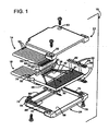
- Figure 1 shows an exploded view of a cable terminal 10.
- the terminal includes a printed circuit board 12 to which are connected a first ribbon cable 14, and a second ribbon cable 16.
- a plurality of spring pins 20 are also connected to the board.
- a housing having an upper shell half 22 and a lower shell half 24 encloses the board.
- the printed circuit board is a generally rectangular shape having a cable attachment edge 26 and an opposed pin attachment edge 30.
- the board includes a pattern of exposed pads and covered traces, all formed of conductive material such as copper foil.
- the pattern includes an elongated ground bar 34 parallel to and adjacent to the cable attachment edge 26. Adjacent to and parallel to the ground bar is an array 36 of separate signal pads 40, each pad being perpendicular to edge 26.
- An array 42 of elongated pin attachment pads 44 is positioned along the entire length of the pin attachment edge 30 of the board. Each pad is an exposed elongated element having an axis perpendicular to the board edge 30.
- the array 42 has an odd number of pads, with the end most pads being considered as odd numbered. All odd numbered pads are connected by way of traces on the board surface, and/or buried ground planes to be discussed below, to the ground bar 34. The interspersed even pads are each independently connected to a corresponding signal pad 40.
- the board has a lower major face 46 that is patterned the same as the upper face 32, so that all features and functions of the upper surface have a corresponding feature or function on the lower surface.
- the board includes multiple buried ground planes at different depths, as will be discussed below with respect to Figure 2 .
- the board is 35.4 mm (1.395 inch) wide by 23.7 mm (0.935 inch) long (from edge 26 to edge 30). It has a thickness of 1.35 mm (0.053 inch), and is formed of GETEK laminates.
- the ground bar 34 is 2.5 mm (0.10 inch) wide and 18.0 mm (0.71 inch) long.
- the signal pads are spaced apart at 1.68 mm (0.066 inch) center to center, and each pad is 0.89 mm (0.035 inch) wide and 2.3 mm (0.090 inch) long.
- the PCB could also be a piece of metal shim stock.
- the pin pads 44 are spaced apart at 1.9 mm (0.075 inch) center to center, and each pad is 0.64 mm (0.025 inch) wide and 1.3 mm (0.50 inch) long.
- the cables 14 and 16 are identical, each with 16 wires 50 (the number of which may vary as noted above with respect to the signal pads.) Each cable is formed as a ribbon with the wires connected to each other side-by-side, at least at the ends.
- the wire s are coaxial, with a central signal-carrying conductor 52 surrounded by a dielectric 54, which is wrapped by a conductive shield 56.
- a jacket 60 surrounds the shield.
- the central conductor is 34 gauge
- the dielectric has a diameter of 0.62 mm (0.0245 inch)
- the shield is a copper foil.
- the jacket is formed of PVC.
- the wires are arranged with a spacing of 1.68 mm (0.066 inch), the same as that of the signal pads 40 on the board.
- the spring pins 20 each include a metal sleeve 62 that receives a pin assembly 64 having an enlarged portion 65 containing electrical components as will be discussed below.
- An end portion of the pin protrudes from one end of the sleeve, and the pin slides axially within the sleeve.
- a spring in the sleeve at the other end biases the pin to an extended position (shown), and allows the pin to move into the sleeve under axial pressure, such as when the pin assembly is pressed toward a hard surface.
- the housing elements 22, 24 are essentially identical. Each is a tray-shaped shell having a planar major wall 66, with peripheral side walls 70, 72, and a single end wall 74 extending perpendicularly from the major wall.
- the major wall 66 may incorporate features which vary in distance from the electrical elements of the board assembly 12. These features exist to maintain the consistency of the electrical ground return path (impedance).
- a front edge 76 of the major wall 66 has no wall attached.
- the end wall defines a cutout 80 that is a central section of the wall having a lower rim. The edges of the end wall at the cutout are semi-circularly radiused to receive a cable without sharp corners that may generate strain and impair cable performance.
- the inner surfaces of the housing elements are coated with a conductive material such as Chomerics CHO-ShieldTM coatings to provide a shield against electrical and magnetic interference.
- the inner surfaces include all surfaces that face the printed circuit board 12.
- the housing is formed of plastic, and has a typical wall thickness of 1.0 mm (0.040 inch).
- a pair of screw fasteners is used to secure the halves together, passing through bores 82 in the upper half 22, and engaging smaller bores 84 in the lower half.
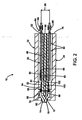
- FIG. 2 shows the assembled terminal 10.
- the sleeves 62 of the spring pins 20 are soldered to the spring pin pads 44, so that the free ends of the pins protrude beyond the edge 30 of the board 12, and beyond the edge 76 of the housing elements 22, 24.
- Each spring pin element contains a compressed coil spring 88 as illustrated.
- the cables 14, 16 are connected to the board, with each exposed central conductor 52 soldered to a respective pad 40, and all the shields of each ribbon soldered to the ground bar 34.
- the ribs 86 press against the shields, so that the conductive layer 90 makes ohmic contact to ground the housing.
- the board 12 has several interior buried ground planes. At a minimum, the board has two ground planes 92, 94, each equally spaced apart from the nearest major surface. The requirement for two ground planes exists because the spacing 96 between the rows of pins is pre-defined by design rules and the needs of the application. However, the spacing of the ground plane from the surface conductors is based on electrical design factors that are used to generate performance characteristics comparable to the coaxial wires.
- the housing conductive layer 90 and ground plane serve the same function as the shield of the coaxial wire; the alternating grounded pins provide lateral shielding with respect to adjacent pins.
- a ground via 98 connects to all of the ground planes, and to the ground bars 34. The number and placement of the ground vias will vary with different designs.
- ground planes may also reside on the outer surfaces of the board, to provide improved additional shielding and improve the ground return path of the signals.
- ground planes 92 and 94 extend under the region of the pins. Deeper ground planes 100, 102 serve to provide shielding and impedance control away from the pins, where foil traces extend across the circuit board. Although not shown, there are connections between the ground planes 100, 102 and the via 98.
- the spring pins and receptacles were chosen in concert with the locations of ground planes and the design of the housing to preserve the matched impedance characteristics of the electrical signal.
- Figure 3 shows the spring pin 20 in which the pin assembly 64 is biased in the extended position by a spring 110 in the sleeve 62.
- the pin assembly includes two conductive metal portions.
- a first pin portion 112 has an elongated shaft 114, the majority of which is closely received in the sleeve.
- the shaft has a rear end 116 against which the spring presses.
- the first portion 112 terminates at the free end with an nail-head-like flange 120 having a flat circular surface 122 extending axially away from the pin, perpendicular to and centered on the pin axis.
- the flange has a cylindrical peripheral surface 124 having a diameter larger than the sleeve, although this may vary in alternative embodiments.
- a second portion 126 of the pin is positioned forward of the first portion, and has a minimal length shaft 130 having a free end 132 having one or more sharp probe points 134.
- the shaft terminates at its rear end facing the first pin portion with a flange 136 shaped and sized the same as the first portion flange 120, with a rear surface 140 facing and parallel to the surface 122 of the first portion flange face.
- the pin portion shafts are aligned on a common axis.
- the flange surfaces are mechanically and electrically connected to a resistor 142 and a capacitor 144 that are connected in parallel between the flanges.
- Each of these electronic components has a end pole face with metallization that facilitates soldering directly to the pin flange for a strong mechanical connection that provides structural support for the second pin portion.
- the components are of unequal size and the mechanical shape of the flange must be shaped, (such as with a step) to accommodate the different dimensions.
- the sleeve can provide mechanical strength to compensate when components are fragile, or too small or otherwise unsuited to provide substantial strength.
- a plastic sleeve 146 encloses the flanges and components. The sleeve fits the flange peripheries closely, so that it can be sealed with a wicking adhesive such as cyanoacrylate. The sleeve has a length adequate to entirely cover the flanges without overhang.
- the sleeve is formed of gold-plated nickel/silver, and has a length of 7.4 mm (0.292 inch), a diameter of 0.64 mm (0.025 inch), and an interior bore diameter of 0.51 mm (0.020 inch).
- the pin's first portion 112 has a shaft length of 2.1 mm (0.084 inch), a shaft diameter of 0.38 mm (0.015 inch), a flange diameter of 0.51 mm (0.020 inch), and a flange thickness or axial length of 0.25 mm (0.010 inch).
- the pin's second portion 126 has a shaft length of 0.38 mm (0.015 inch), and a shaft diameter of 0.51 mm (0.020 inch).
- the pin portion shaft diameters is the same in the preferred embodiment, although this need not be the case for alternative embodiments where mechanical constraints of the probe tip and the sleeve bore may provide advantages to having different diameters.
- the second portion has a flange diameter of 0.51 mm (0.020 inch), and a flange thickness or axial length of 0.25 mm (0.010 inch).
- the 0.64 mm (0.025 inch) overall length of the second pin portion 126 provides significant advantages in that this very limited length between the device being probed and the electrical components 142 and 144 yields an extremely high self resonance of 12 GHz, which allows useful operation up to this frequency limit.
- the second portion length can be reduced to any practical limit, including using electrical components formed with end features.
- the second portion tip protrudes only sufficiently that angular misalignment or raised components on the device under test do not cause unwanted contact by the flange or sleeve.
- the second portion provides a beneficial combination of electrical performance and mechanical geometry when its length is less than double the flange diameter. Also, these benefits are achieved when the length is less than 1.3 mm (0.050 inch), because this provides an adequately low loss tangent that absorbs transmitted energy.
- a typical loss tangent for a conventional trace on KaptonTM polyimide is 0.0030 while the preferred embodiment achieves a loss tangent of zero, because the conductive portion (metal tip) of the probe between the device under test and the RC components is surrounded by air, and not mounted on film or a PC Board. Comparative performance (0.69 mm (0.027 inch) diameter signal, 50 ohm) is described in the table below.
- the mass of the second pin portion is so much less than the entire pin plus sleeve of the prior art, it achieves reactive inductance significantly lower than the prior art, which must rely on passive RC components on the printed circuit board adjacent to the sleeve.
- the ratio of the lengths of second portion to the first portion is less than 1 in 10, and the ratio of the mass of the second portion to that of the first portion and sleeve is less than 1:3.
- FIG. 4 shows the preferred embodiment probe assembly 200 for a cable terminal.
- the assembly includes a frame 202, an array of probes 204 connected to the frame, several coaxial cables 206 connected to the probes.
- a lower lid 210 and an upper lid 212 enclose the frame and probes, so that the pins protrude beyond the periphery of one side, and the cables extend from the other side. Threaded screws 214 and nuts 216 secure the lids together.
- the frame 202 is a rectangular body with a large central opening.
- the frame has a first edge member 220 that supports the ends of the cables 206 and the rear ends of the probes 204.
- An opposed second edge member 222 supports the opposite ends of the probes, and side edge members 224 and 226 connect the first and second edge members.
- the first edge member defines a series of channels 230, each having a width to closely accommodate a cable end portion from which the outer sheath 232 has been stripped to expose a shield layer 234.
- the shield covers a dielectric layer 236 that surrounds a central signal conductor 240. The depth of each channel is less than half of the shield diameter, so that the entire central conductor remains above the upper surface 242 of the frame.
- the channels are spaced apart from each other to provide lands 244 between adjacent cable shields.
- the entire upper surface242 of the frame is covered with a thin copper foil layer 246 in the manner of a printed circuit board, so that the lands 244 are conductive. This provides for soldering the shields and some of the probes to the first frame portion as will be discussed below.
- the second edge member 222 of the frame also has an array of channels 250 that define an array of lands 252 between them. These lands are also covered with copper foil, so that the probes may be soldered.
- the channels 250 are arrayed at a pitch double that of the channels 230 of the first edge, with a minimal depth adequate to isolate the conductive land surfaces from each other.
- the coax cable is 34 AWG
- the first channels have a center-to-center spacing of 0.83 mm (0.033 inch) (Signal to Ground)
- the second channels have a spacing of 1.68 mm (0.066 inch) (Signal to Signal).
- the frame has a length of 31.8 mm (1.250 inch), a thickness of 6.1 mm (0.240 inch), and a width (for an embodiment with 19 cables and 38 probes) of 25 mm (1.000 inch).
- the frame's first edge has a width of 0.64 mm (0.025 inch), and opposite edge a width of 6.4 mm (0.250 inch), and sides edges a width of 4.4 mm (0.175 inch).
- Each probe 204 includes a tubular cylindrical sleeve 254 and a pin 256 partially received within the sleeve.
- each sleeve has a rear end 260 adjacent to the cable 206, and a forward end 262 from which the pin 256 protrudes.
- the pin has a rear end 264 contacting a compression coil spring 266 received in the sleeve bore.
- a necked portion 270 of the sleeve provides rearward support for the spring at an intermediate portion of the sleeve.
- the pin has a sharp tip 272 that protrudes from the forward end 262 of the sleeve.
- half of the probes are connected to the signal conductors of the cables, and half are connected to the shields to serve as ground conductors. These are arranged in alternating fashion in an evenly spaced array of parallel probes that has a ground probe at each end of the array. All of the probes are supported at the forward ends of their sleeves by the forward frame element 222. The forward ends of the sleeves are ohmically connected to the foil layer 246 with solder 274. The sleeve end does not extend beyond the frame edge, while an extending portion 276 protrudes well beyond the sleeve and frame.
- each signal-carrying probe is connected to the signal conductor 240 of a respective cable.
- the conductor is inserted into and is closely received by the bore at the rear end of the sleeve, and is soldered for an ohmic connection.
- the ground probes are connected as shown in Figure 6 .
- the rear ends of the sleeves 254 rest on the lands 244 between the cables at the exposed shield portions.
- a connection of solder 276 connects each shield 234 and sleeve to each adjacent land, so that all the shields are interconnected, as are the ends of the ground probe sleeves.
- the sleeves have a diameter of 0.69 mm (0.027 inch), so that with the preferred spacing, there is a space of 0.15 mm (0.006 inch) between adjacent sleeves.
- the ground probe sleeves are longer than the signal probe sleeves, because the ground sleeves must overlap the first frame edge to overlay the lands, while the signal probe sleeves need not overlap the lands, since the cable shield and dielectric portions extend to the edge of the frame portion, and the signal sleeves need not even fully reach the end of the dielectric.
- the cables may be positioned that the ends of the dielectric and shields do not reach the edge of the frame portion, but stop at an intermediate position. With this, a common sleeve size may be used, so that the ground sleeves overlap the frame portion while the signal sleeves also overlap the frame portion without interfering with the dielectric.
- the illustrated embodiment provides a consistent signal and ground path length because contact or lack of contact between the pin shank and the forward aperture of a sleeve does not affect the path length.
- the frame and sleeves are contained within a plastic box formed by the upper lid 212 and lower lid 210.
- the lids define a chamber 280 that provides an air space between the probes, and between the sleeves and each surface.
- a forward wall 282 of the box is positioned just forward of the forward ends of the sleeves, and has a minimal thickness of 0.64 mm (0.025 inch) to avoid excessive free pin length.
- the forward wall defines an array of apertures formed by semicircular cutouts 284 at the rims of the upper and lower lids. These apertures are sized to closely accommodate the pins without contact or friction.
- the box has a rear wall 286 that defines larger apertures also formed by semicircular cutouts 290 of the lid rims.
- the chamber has a depth of 2.0 mm (0.080 inch) between the major surface of the lids, providing substantial clearance between the sleeves and the lid.
Abstract
Description
- This invention relates to electrical probes, and more particularly to probes for high speed cables terminals with multiple conductors.
- Certain high speed electronic cable terminals employ arrays of spring pins to contact pads or lands of a circuit board or integrated circuit under test, or to contact connections of an electronic device for a permanent connection. The spring pins are straight, elongated pins received in cylindrical sleeves, and which are axially biased by spring pressure to an extended position. All pins extend in the same direction, with all the pin tips in a common plane. Contact is made by aligning the terminal with the device being probed or contacted, and applying axial pressure to ensure contact by each pin with a minimum pressure. The range of motion of each pin accommodates contour variations in the device being contacted, and slight variations in the position of each pin.
- For applications in which very high frequency signals are to be transmitted, the cable to which the terminal is connected may be formed of coaxial wires, each shielded to provide consistent performance and to prevent cross talk and other electronic interference. A terminal housing having a metal shield layer encloses the sleeves retaining the pins. One such particularly effective device is shown in
U.S. Patent No. 6,575,772 to Soubh. This prior art connector has proven effective at providing a high impedance/high frequency probe assembly with relatively small probe spacing. It is believed to be useful for frequencies as high as 5 GHz. However, while effective, this limitation prevents usage for higher frequency applications. - Other prior art embodiments have sought to provide a high-speed connector with a metal block having sleeved spring pins inserted and protruding beyond the periphery of the block. While adequate for some applications, these suffer from certain performance variations between different connectors. Signals are carried through sleeves that are insulated from the block, and ground signals are carried through sleeves that are connected to the block. The ohmic connection between a ground pin sleeve and the block normally occurs near the periphery of the block, because the sleeve has a slightly wider portion at its end adjacent to the aperture from which the spring pin emerges. Thus, a ground signal is conducted from the pin tip, down the length of the pin to the spring at the opposite end of the pin, which bears on the sleeve. The ground signal then passes along the sleeve in the reverse direction until it reaches the point of contact where the sleeve bulges and is press-fit within the block, after which the ground signal is conducted through the block in the original direction. However, if the pin makes contact with the sleeve near the sleeve aperture, or if the sleeve makes contact with the block well away from the aperture, the ground signal path is substantially shortened, avoiding the zigzagging path described above in the nominal case. This possibility can lead to inconsistent performance between ground conductors, impairing results.
-
DE 79 14 951 U1 , on which the preamble ofclaim 1 is based, discloses a device in which a plurality of spring-biased probes are connected to a body. Each probe includes a sleeve portion from which a pin extends. The probes are positioned adjacent one another and each sleeve portion has a first end that can be connected to a conductor, a second end attached to a body, and an intermediate portion. -
DE 38 15 573 A1 discloses a test adapter for an inspection device for examining electrical or electronic samples. The test adapter has a plurality of probes connected to a body. Each probe has a sleeve with a spring-loaded contact pin having a contact head and each sleeve has an intermediate portion suspended out of contact with the body. One end of the sleeve extends slightly beyond the body and the end of the pin having the contact tip protrudes from this sleeve end. Each probe also has two resilient tabs for holding the probe in a bore in a plate of the body. -
DE 35 00 226 A1 discloses a probe needle for a printed circuit board testing device. The probe needle is connected to a body and has a spring-biased pin with a contact tip. The pin comprises a sleeve with a collar and the sleeve fits over an end of a shaft around which the spring for the pin is mounted. The end of the pin with the contact tip extends beyond the body and the collar is within the body and prevents the needle from fully coming out of the body by engaging a guide plate of the body through which the pin extends. During the testing process, a printed circuit board is pressed against the testing device comprising a large number of probe needles. When the board is removed, the probe needles spring out but they are retained by the body on account of the needle collars. - The present invention overcomes the limitations of the prior art by providing an electrical connector comprising a body; a plurality of probes connected to the body; each probe having a spring biased pin with a contact tip; each probe including a sleeve portion receiving the pin; and each sleeve portion having a first end, a second end connected to the body and from which the pin protrudes, and an intermediate portion suspended out of contact with the body, characterized by a plurality of coaxial cables connected to the body, each cable having a signal conductor surrounded by a conductive shield, the probes being arranged in an array with the first end of the sleeve portion of every other probe being connected to a respective incoming signal conductor, and the remaining probes connected to the shields. The sleeve may be spaced apart from adjacent sleeves, and suspended in air except at their ends.
-
-
Figure 1 is an exploded perspective view of a cable terminal assembly. -
Figure 2 is a sectional side view of the assembly ofFigure 1 . -
Figure 3 is a sectional side view of a probe pin assembly according to the preferred embodiment. -
Figure 4 is an exploded perspective view of a cable terminal assembly according to an preferred embodiment of the invention. -
Figure 5 is a sectional side view of the assembly ofFigure 4 taken along line 5-5. -
Figure 6 is a sectional axial view of the assembly ofFigure 4 taken along line 6-6. -
Figure 1 shows an exploded view of acable terminal 10. The terminal includes a printedcircuit board 12 to which are connected afirst ribbon cable 14, and asecond ribbon cable 16. A plurality ofspring pins 20 are also connected to the board. A housing having anupper shell half 22 and alower shell half 24 encloses the board. - The printed circuit board is a generally rectangular shape having a
cable attachment edge 26 and an opposedpin attachment edge 30. The board includes a pattern of exposed pads and covered traces, all formed of conductive material such as copper foil. Referring to an uppermajor face 32 of the board, the pattern includes anelongated ground bar 34 parallel to and adjacent to thecable attachment edge 26. Adjacent to and parallel to the ground bar is anarray 36 ofseparate signal pads 40, each pad being perpendicular toedge 26. - An
array 42 of elongated pin attachment pads 44 is positioned along the entire length of thepin attachment edge 30 of the board. Each pad is an exposed elongated element having an axis perpendicular to theboard edge 30. Thearray 42 has an odd number of pads, with the end most pads being considered as odd numbered. All odd numbered pads are connected by way of traces on the board surface, and/or buried ground planes to be discussed below, to theground bar 34. The interspersed even pads are each independently connected to acorresponding signal pad 40. - The board has a lower
major face 46 that is patterned the same as theupper face 32, so that all features and functions of the upper surface have a corresponding feature or function on the lower surface. The board includes multiple buried ground planes at different depths, as will be discussed below with respect toFigure 2 . In the exemplary connector, the board is 35.4 mm (1.395 inch) wide by 23.7 mm (0.935 inch) long (fromedge 26 to edge 30). It has a thickness of 1.35 mm (0.053 inch), and is formed of GETEK laminates. Theground bar 34 is 2.5 mm (0.10 inch) wide and 18.0 mm (0.71 inch) long. There are 16signal pads 40 on each face in the exemplary connector, although this may be varied depending on the application. The signal pads are spaced apart at 1.68 mm (0.066 inch) center to center, and each pad is 0.89 mm (0.035 inch) wide and 2.3 mm (0.090 inch) long. In alternative connectors, the PCB could also be a piece of metal shim stock. The pin pads 44 are spaced apart at 1.9 mm (0.075 inch) center to center, and each pad is 0.64 mm (0.025 inch) wide and 1.3 mm (0.50 inch) long. - The
cables conductor 52 surrounded by a dielectric 54, which is wrapped by aconductive shield 56. Ajacket 60 surrounds the shield. In the exemplary connector, the central conductor is 34 gauge, the dielectric has a diameter of 0.62 mm (0.0245 inch), and the shield is a copper foil. The jacket is formed of PVC. The wires are arranged with a spacing of 1.68 mm (0.066 inch), the same as that of thesignal pads 40 on the board. - The spring pins 20 each include a
metal sleeve 62 that receives apin assembly 64 having anenlarged portion 65 containing electrical components as will be discussed below. An end portion of the pin protrudes from one end of the sleeve, and the pin slides axially within the sleeve. A spring in the sleeve at the other end biases the pin to an extended position (shown), and allows the pin to move into the sleeve under axial pressure, such as when the pin assembly is pressed toward a hard surface. - The
housing elements major wall 66, withperipheral side walls single end wall 74 extending perpendicularly from the major wall. Themajor wall 66 may incorporate features which vary in distance from the electrical elements of theboard assembly 12. These features exist to maintain the consistency of the electrical ground return path (impedance). Afront edge 76 of themajor wall 66 has no wall attached. The end wall defines acutout 80 that is a central section of the wall having a lower rim. The edges of the end wall at the cutout are semi-circularly radiused to receive a cable without sharp corners that may generate strain and impair cable performance. The inner surfaces of the housing elements are coated with a conductive material such as Chomerics CHO-Shield™ coatings to provide a shield against electrical and magnetic interference. The inner surfaces include all surfaces that face the printedcircuit board 12. Thus, when assembled, there is a metallic enclosure that it open only at the slot to receive the cable, and at the side where the pins protrude. The housing is formed of plastic, and has a typical wall thickness of 1.0 mm (0.040 inch). A pair of screw fasteners is used to secure the halves together, passing throughbores 82 in theupper half 22, and engagingsmaller bores 84 in the lower half. -
Figure 2 shows the assembledterminal 10. Thesleeves 62 of the spring pins 20 are soldered to the spring pin pads 44, so that the free ends of the pins protrude beyond theedge 30 of theboard 12, and beyond theedge 76 of thehousing elements compressed coil spring 88 as illustrated. Thecables central conductor 52 soldered to arespective pad 40, and all the shields of each ribbon soldered to theground bar 34. Theribs 86 press against the shields, so that theconductive layer 90 makes ohmic contact to ground the housing. - The
board 12 has several interior buried ground planes. At a minimum, the board has twoground planes
The requirement for two ground planes exists because thespacing 96 between the rows of pins is pre-defined by design rules and the needs of the application. However, the spacing of the ground plane from the surface conductors is based on electrical design factors that are used to generate performance characteristics comparable to the coaxial wires. The housingconductive layer 90 and ground plane serve the same function as the shield of the coaxial wire; the alternating grounded pins provide lateral shielding with respect to adjacent pins. A ground via 98 connects to all of the ground planes, and to the ground bars 34. The number and placement of the ground vias will vary with different designs. - In addition, different portions of the board and circuit may have different impedance characteristics, and may require different ground plane spacings to achieve uniform impedance results. Ground planes may also reside on the outer surfaces of the board, to provide improved additional shielding and improve the ground return path of the signals. In the exemplar connector, ground planes 92 and 94 extend under the region of the pins. Deeper ground planes 100, 102 serve to provide shielding and impedance control away from the pins, where foil traces extend across the circuit board. Although not shown, there are connections between the ground planes 100, 102 and the via 98.
- The spring pins and receptacles were chosen in concert with the locations of ground planes and the design of the housing to preserve the matched impedance characteristics of the electrical signal.
-
Figure 3 shows thespring pin 20 in which thepin assembly 64 is biased in the extended position by aspring 110 in thesleeve 62. The pin assembly includes two conductive metal portions. Afirst pin portion 112 has an elongatedshaft 114, the majority of which is closely received in the sleeve. The shaft has arear end 116 against which the spring presses. Thefirst portion 112 terminates at the free end with an nail-head-like flange 120 having a flatcircular surface 122 extending axially away from the pin, perpendicular to and centered on the pin axis. The flange has a cylindricalperipheral surface 124 having a diameter larger than the sleeve, although this may vary in alternative embodiments. - A
second portion 126 of the pin is positioned forward of the first portion, and has aminimal length shaft 130 having afree end 132 having one or more sharp probe points 134. The shaft terminates at its rear end facing the first pin portion with aflange 136 shaped and sized the same as thefirst portion flange 120, with arear surface 140 facing and parallel to thesurface 122 of the first portion flange face. The pin portion shafts are aligned on a common axis. - The flange surfaces are mechanically and electrically connected to a
resistor 142 and acapacitor 144 that are connected in parallel between the flanges. Each of these electronic components has a end pole face with metallization that facilitates soldering directly to the pin flange for a strong mechanical connection that provides structural support for the second pin portion. Sometimes the components are of unequal size and the mechanical shape of the flange must be shaped, (such as with a step) to accommodate the different dimensions. Also, the sleeve can provide mechanical strength to compensate when components are fragile, or too small or otherwise unsuited to provide substantial strength. To provide additional structural support, and to protect the components with a mechanical barrier and environmental seal, aplastic sleeve 146 encloses the flanges and components. The sleeve fits the flange peripheries closely, so that it can be sealed with a wicking adhesive such as cyanoacrylate. The sleeve has a length adequate to entirely cover the flanges without overhang. - In the preferred embodiment, the sleeve is formed of gold-plated nickel/silver, and has a length of 7.4 mm (0.292 inch), a diameter of 0.64 mm (0.025 inch), and an interior bore diameter of 0.51 mm (0.020 inch). The pin's
first portion 112 has a shaft length of 2.1 mm (0.084 inch), a shaft diameter of 0.38 mm (0.015 inch), a flange diameter of 0.51 mm (0.020 inch), and a flange thickness or axial length of 0.25 mm (0.010 inch). The pin'ssecond portion 126 has a shaft length of 0.38 mm (0.015 inch), and a shaft diameter of 0.51 mm (0.020 inch). The pin portion shaft diameters is the same in the preferred embodiment, although this need not be the case for alternative embodiments where mechanical constraints of the probe tip and the sleeve bore may provide advantages to having different diameters. The second portion has a flange diameter of 0.51 mm (0.020 inch), and a flange thickness or axial length of 0.25 mm (0.010 inch). - The 0.64 mm (0.025 inch) overall length of the
second pin portion 126 provides significant advantages in that this very limited length between the device being probed and theelectrical components - It is believed that the second portion provides a beneficial combination of electrical performance and mechanical geometry when its length is less than double the flange diameter. Also, these benefits are achieved when the length is less than 1.3 mm (0.050 inch), because this provides an adequately low loss tangent that absorbs transmitted energy. A typical loss tangent for a conventional trace on Kapton™ polyimide is 0.0030 while the preferred embodiment achieves a loss tangent of zero, because the conductive portion (metal tip) of the probe between the device under test and the RC components is surrounded by air, and not mounted on film or a PC Board. Comparative performance (0.69 mm (0.027 inch) diameter signal, 50 ohm) is described in the table below.
Loss tangent Dielectric constant Loss per foot @ 10GHz -3dB loss @ 1 foot Kapton™ 0.0030 3.40 -3.72 dB 5.60 GHz Extruded FEP 0.0007 2.03 -3.12 dB 8.90 GHz Taped PTFE 0.0007 1.35 -2.85 dB 13.0 GHz Air 0.0000 1.00 -2.70 dB 20.0 GHz - Because the mass of the second pin portion is so much less than the entire pin plus sleeve of the prior art, it achieves reactive inductance significantly lower than the prior art, which must rely on passive RC components on the printed circuit board adjacent to the sleeve.
- The ratio of the lengths of second portion to the first portion (including sleeve) is less than 1 in 10, and the ratio of the mass of the second portion to that of the first portion and sleeve is less than 1:3. These low ratios provide an indication of the relative advantage of the preferred embodiment over solid pins with RC components mounted on the circuit board.
-
Figure 4 shows the preferredembodiment probe assembly 200 for a cable terminal. The assembly includes aframe 202, an array ofprobes 204 connected to the frame, severalcoaxial cables 206 connected to the probes. Alower lid 210 and anupper lid 212 enclose the frame and probes, so that the pins protrude beyond the periphery of one side, and the cables extend from the other side. Threaded screws 214 andnuts 216 secure the lids together. - The
frame 202 is a rectangular body with a large central opening. The frame has afirst edge member 220 that supports the ends of thecables 206 and the rear ends of theprobes 204. An opposedsecond edge member 222 supports the opposite ends of the probes, andside edge members channels 230, each having a width to closely accommodate a cable end portion from which theouter sheath 232 has been stripped to expose ashield layer 234. The shield covers adielectric layer 236 that surrounds acentral signal conductor 240. The depth of each channel is less than half of the shield diameter, so that the entire central conductor remains above theupper surface 242 of the frame. The channels are spaced apart from each other to providelands 244 between adjacent cable shields. The entire upper surface242 of the frame is covered with a thincopper foil layer 246 in the manner of a printed circuit board, so that thelands 244 are conductive. This provides for soldering the shields and some of the probes to the first frame portion as will be discussed below. - The
second edge member 222 of the frame also has an array ofchannels 250 that define an array oflands 252 between them. These lands are also covered with copper foil, so that the probes may be soldered. Thechannels 250 are arrayed at a pitch double that of thechannels 230 of the first edge, with a minimal depth adequate to isolate the conductive land surfaces from each other. In the preferred embodiment, the coax cable is 34 AWG, the first channels have a center-to-center spacing of 0.83 mm (0.033 inch) (Signal to Ground), and the second channels have a spacing of 1.68 mm (0.066 inch) (Signal to Signal). The frame has a length of 31.8 mm (1.250 inch), a thickness of 6.1 mm (0.240 inch), and a width (for an embodiment with 19 cables and 38 probes) of 25 mm (1.000 inch). The frame's first edge has a width of 0.64 mm (0.025 inch), and opposite edge a width of 6.4 mm (0.250 inch), and sides edges a width of 4.4 mm (0.175 inch). - Each
probe 204 includes a tubularcylindrical sleeve 254 and apin 256 partially received within the sleeve. As shown inFigure 5 , each sleeve has arear end 260 adjacent to thecable 206, and aforward end 262 from which thepin 256 protrudes. The pin has arear end 264 contacting acompression coil spring 266 received in the sleeve bore. Anecked portion 270 of the sleeve provides rearward support for the spring at an intermediate portion of the sleeve. The pin has asharp tip 272 that protrudes from theforward end 262 of the sleeve. - Referring back to
Figure 4 , half of the probes are connected to the signal conductors of the cables, and half are connected to the shields to serve as ground conductors. These are arranged in alternating fashion in an evenly spaced array of parallel probes that has a ground probe at each end of the array. All of the probes are supported at the forward ends of their sleeves by theforward frame element 222. The forward ends of the sleeves are ohmically connected to thefoil layer 246 withsolder 274. The sleeve end does not extend beyond the frame edge, while an extendingportion 276 protrudes well beyond the sleeve and frame. - The rear ends of the sleeves are supported and connected differently depending on whether they are signal carriers, or the interdigitated ground carriers. As shown in
Figure 5 each signal-carrying probe is connected to thesignal conductor 240 of a respective cable. The conductor is inserted into and is closely received by the bore at the rear end of the sleeve, and is soldered for an ohmic connection. The ground probes are connected as shown inFigure 6 . The rear ends of thesleeves 254 rest on thelands 244 between the cables at the exposed shield portions. A connection ofsolder 276 connects eachshield 234 and sleeve to each adjacent land, so that all the shields are interconnected, as are the ends of the ground probe sleeves. The sleeves have a diameter of 0.69 mm (0.027 inch), so that with the preferred spacing, there is a space of 0.15 mm (0.006 inch) between adjacent sleeves. - The ground probe sleeves are longer than the signal probe sleeves, because the ground sleeves must overlap the first frame edge to overlay the lands, while the signal probe sleeves need not overlap the lands, since the cable shield and dielectric portions extend to the edge of the frame portion, and the signal sleeves need not even fully reach the end of the dielectric. In an alternative embodiment, the cables may be positioned that the ends of the dielectric and shields do not reach the edge of the frame portion, but stop at an intermediate position. With this, a common sleeve size may be used, so that the ground sleeves overlap the frame portion while the signal sleeves also overlap the frame portion without interfering with the dielectric.
- The illustrated embodiment provides a consistent signal and ground path length because contact or lack of contact between the pin shank and the forward aperture of a sleeve does not affect the path length. A signal passing through the pin or the sleeve, or both, follows the same length path without the disadvantages of the prior art described above.
- Referring back to
Figure 5 , the frame and sleeves are contained within a plastic box formed by theupper lid 212 andlower lid 210. The lids define achamber 280 that provides an air space between the probes, and between the sleeves and each surface. Aforward wall 282 of the box is positioned just forward of the forward ends of the sleeves, and has a minimal thickness of 0.64 mm (0.025 inch) to avoid excessive free pin length. The forward wall defines an array of apertures formed bysemicircular cutouts 284 at the rims of the upper and lower lids. These apertures are sized to closely accommodate the pins without contact or friction. The box has arear wall 286 that defines larger apertures also formed bysemicircular cutouts 290 of the lid rims. These are sized slightly smaller than the overall diameter of the sheathed cable, so that the cable sheathing is slightly compressed when the lids are secured to each other, in the manner of a strain relief, to protect the solder joints from strain. In the preferred embodiment the chamber has a depth of 2.0 mm (0.080 inch) between the major surface of the lids, providing substantial clearance between the sleeves and the lid. - While the above is discussed in terms of preferred embodiments, the invention is limited by the content of the claims alone.
Claims (14)
- An electrical connector comprising
a body (202);
a plurality of probes (204) connected to the body (202);
each probe (204) having a spring biased pin (256) with a contact tip (272);
each probe (204) including a sleeve portion (254) receiving the pin (256); and
each sleeve portion (254) having a first end (260), a second end (262) connected to the body (202) and from which the pin (256) protrudes, and an intermediate portion suspended out of contact with the body (202), characterized by:a plurality of coaxial cables (206) connected to the body (202), each cable (206) having a signal conductor (240) surrounded by a conductive shield (234), the probes (204) being arranged in an array with the first end (260) of the sleeve portion (254) of every other probe being connected to a respective incoming signal conductor (240), and the remaining probes connected to the shields (234). - The connector of claim 1, wherein each sleeve portion (254) is spaced apart from adjacent sleeve portions without intervening material.
- The connector of claim 1 or 2, wherein the intermediate portion of each sleeve portion (254) is suspended in air and each sleeve portion (254) is spaced apart from adjacent sleeve portions.
- The connector of any preceding claim, wherein the first ends of the sleeve portions (254) of the remaining probes are interdigitated with the shields (234) in an alternating pattern.
- The connector of any preceding claim, wherein the second ends (262) of the sleeve portions (254) are each connected to respective metallized pads (246) on a first array of pads (252).
- The connector of any preceding claim, wherein the body (202) has a peripheral edge and wherein the pins (256) extend beyond the body (202).
- The connector of any preceding claim, wherein each probe (204) provides a generally linear conductive path from the tip (272) of the pin (256), through the length of the pin (256) to an opposite end of the pin (256) in contact with a spring (266), through the spring (266) to a contacting portion (270) of the sleeve portion (254), and through a remaining portion of the sleeve portion to the incoming conductor (240), such that the conductive path does not rely on possible lateral contact between an intermediate portion of the pin (256) and the first end (260) of the sleeve portion (254).
- The connector of any preceding claim, wherein the body (202) is a circuit element having a first linear portion (222) supporting the sleeve portions (254) at their second ends (262), and a second linear portion (220) spaced apart from the first linear portion (222) supporting at least some of the sleeve portions (254) at their first ends.
- The connector of any preceding claim, wherein the body (202) is a frame supporting the ends of the sleeve portions (254), and having an opening registered with the intermediate portion of the sleeve portions (254).
- The connector of any preceding claim, wherein the body (202) includes metallized surface portions (246) to which the ends of the sleeve portions (254) are soldered.
- The connector of claim 10, wherein the metallized surface portions include a first array of pads (246,244), each positioned between adjacent said incoming conductors (240).
- The connector of claim 11, wherein the shields (234) of the incoming conductors (240) are connected to adjacent pads (246,244) of the first array.
- The connector of claim 12, wherein the shields (234) are connected to each other at the first array.
- The connector of any preceding claim, wherein the sleeve portions (254) comprise two subsets, the members of each subset alternating with each other, and wherein the first ends of the sleeve portions (254) of the members of one of the subsets extend beyond the first ends of the members of the other subset.
Applications Claiming Priority (2)
| Application Number | Priority Date | Filing Date | Title |
|---|---|---|---|
| US10/794,643 US7371128B2 (en) | 2003-10-14 | 2004-03-05 | Cable terminal with air-enhanced contact pins |
| PCT/US2005/007042 WO2005096441A1 (en) | 2004-03-05 | 2005-03-04 | Cable terminal with air-enhanced contact pins |
Publications (2)
| Publication Number | Publication Date |
|---|---|
| EP1721365A1 EP1721365A1 (en) | 2006-11-15 |
| EP1721365B1 true EP1721365B1 (en) | 2010-12-15 |
Family
ID=34961766
Family Applications (1)
| Application Number | Title | Priority Date | Filing Date |
|---|---|---|---|
| EP05724559A Expired - Fee Related EP1721365B1 (en) | 2004-03-05 | 2005-03-04 | Cable terminal with air-enhanced contact pins |
Country Status (6)
| Country | Link |
|---|---|
| US (1) | US7371128B2 (en) |
| EP (1) | EP1721365B1 (en) |
| JP (1) | JP4624405B2 (en) |
| CN (1) | CN1930737B (en) |
| DE (1) | DE602005025314D1 (en) |
| WO (1) | WO2005096441A1 (en) |
Families Citing this family (19)
| Publication number | Priority date | Publication date | Assignee | Title |
|---|---|---|---|---|
| JP2007048491A (en) * | 2005-08-08 | 2007-02-22 | D D K Ltd | Electric connector |
| US7476131B2 (en) * | 2006-09-29 | 2009-01-13 | Nellcor Puritan Bennett Llc | Device for reducing crosstalk |
| US7470155B1 (en) * | 2007-07-25 | 2008-12-30 | Samtec, Inc. | High-density connector |
| JP5563207B2 (en) * | 2008-08-01 | 2014-07-30 | スリーエム イノベイティブ プロパティズ カンパニー | Termination connector |
| US7740508B2 (en) * | 2008-09-08 | 2010-06-22 | 3M Innovative Properties Company | Probe block assembly |
| GB201119050D0 (en) | 2011-11-04 | 2011-12-14 | Rolls Royce Plc | Electrical harness connector |
| GB201119045D0 (en) * | 2011-11-04 | 2011-12-14 | Rolls Royce Plc | Electrical harness |
| KR101277773B1 (en) * | 2012-12-28 | 2013-06-24 | 우진 일렉트로나이트(주) | Replacement device for holder and holder assembly |
| CN103247917A (en) * | 2013-04-11 | 2013-08-14 | 富士康(昆山)电脑接插件有限公司 | Coaxial cable assembly |
| GB201308029D0 (en) | 2013-05-03 | 2013-06-12 | Rolls Royce Plc | Electrical harness connector |
| DE102013225794A1 (en) * | 2013-12-12 | 2015-06-18 | Leoni Kabel Holding Gmbh | Contact connection of shielded data lines on a circuit board and method for contacting a plurality of shielded data lines on a circuit board |
| US9810715B2 (en) * | 2014-12-31 | 2017-11-07 | Tektronix, Inc. | High impedance compliant probe tip |
| WO2018075986A1 (en) * | 2016-10-21 | 2018-04-26 | Paricon Technologies Corporation | Cable-to-board connector |
| US9979136B1 (en) * | 2017-06-26 | 2018-05-22 | Greenconn Corporation | High speed connector and transmission module thereof |
| US9893446B1 (en) * | 2017-06-26 | 2018-02-13 | Greenconn Corp. | High speed connector and transmission module thereof |
| JP7463372B2 (en) * | 2018-11-30 | 2024-04-08 | コーニング オプティカル コミュニケーションズ アールエフ リミテッド ライアビリティ カンパニー | COMPRESSIVE ELECTRICAL CONTACT WITH BRANCHED CUT SECTIONS - Patent application |
| US11092996B2 (en) * | 2019-08-20 | 2021-08-17 | Getac Technology Corporation | Electronic device |
| CN110600944A (en) * | 2019-09-18 | 2019-12-20 | 环胜电子(深圳)有限公司 | Electric connector structure |
| WO2023229627A1 (en) * | 2022-05-25 | 2023-11-30 | Rakuten Symphony Uk Ltd | Spring pin rf coaxial interconnect |
Family Cites Families (22)
| Publication number | Priority date | Publication date | Assignee | Title |
|---|---|---|---|---|
| US3548829A (en) * | 1968-10-21 | 1970-12-22 | Frigitronics Of Conn Inc | Cryosurgical instrument |
| US4041380A (en) | 1976-03-12 | 1977-08-09 | Kastar, Inc. | Multi-function tester with removable circuit cartridge |
| US4209742A (en) * | 1976-10-13 | 1980-06-24 | Tektronix, Inc. | Modular probe system |
| DE7914951U1 (en) | 1979-05-23 | 1989-07-13 | Feinmetall Gmbh, 7033 Herrenberg, De | |
| US4418314A (en) * | 1980-10-20 | 1983-11-29 | The United States Of America As Represented By The Secretary Of The Army | High impedance fast voltage probe |
| JPS58144215U (en) * | 1982-03-23 | 1983-09-28 | 岩崎通信機株式会社 | Capacitance probe of displacement meter |
| GB2125236A (en) | 1982-08-11 | 1984-02-29 | Tektronix Inc | Stress-isolating electrical connections |
| DE3500226A1 (en) | 1985-01-05 | 1986-07-10 | Riba-Prüftechnik GmbH, 7801 Schallstadt | Probe needle for a printed-circuit board testing device |
| US4739259A (en) | 1986-08-01 | 1988-04-19 | Tektronix, Inc. | Telescoping pin probe |
| DE3815573A1 (en) | 1988-05-06 | 1989-11-16 | Feinmetall Gmbh | Test adaptor |
| US4904935A (en) * | 1988-11-14 | 1990-02-27 | Eaton Corporation | Electrical circuit board text fixture having movable platens |
| US5084673A (en) * | 1989-06-15 | 1992-01-28 | Nhk Spring Co., Ltd. | Electric contact probe |
| US5046968A (en) * | 1989-09-28 | 1991-09-10 | Tri-Star Incorporated | Electrical connector contact having an electrical component disposed in a central internal cavity |
| US5103165A (en) * | 1990-11-19 | 1992-04-07 | Static Control Components, Inc. | Insulated, hand-held non-contacting voltage detection probe |
| US5196789A (en) * | 1991-01-28 | 1993-03-23 | Golden Joseph R | Coaxial spring contact probe |
| US5248266A (en) * | 1992-09-15 | 1993-09-28 | Itt Coporation | Connector with sealed component contact |
| JPH10239350A (en) * | 1997-02-25 | 1998-09-11 | Seiko Epson Corp | Test probe for measuring apparatus and tester with the same |
| US6407562B1 (en) * | 1999-07-29 | 2002-06-18 | Agilent Technologies, Inc. | Probe tip terminating device providing an easily changeable feed-through termination |
| US6552523B2 (en) * | 2001-05-24 | 2003-04-22 | Tektronix, Inc. | Combination low capacitance probe tip and socket for a measurement probe |
| US6935866B2 (en) * | 2002-04-02 | 2005-08-30 | Adc Telecommunications, Inc. | Card edge coaxial connector |
| US6575772B1 (en) * | 2002-04-09 | 2003-06-10 | The Ludlow Company Lp | Shielded cable terminal with contact pins mounted to printed circuit board |
| US6688906B2 (en) * | 2002-05-28 | 2004-02-10 | Agilent Technologies Inc. | Probes and methods for testing electrical circuits |
-
2004
- 2004-03-05 US US10/794,643 patent/US7371128B2/en not_active Expired - Fee Related
-
2005
- 2005-03-04 WO PCT/US2005/007042 patent/WO2005096441A1/en not_active Application Discontinuation
- 2005-03-04 JP JP2007502002A patent/JP4624405B2/en not_active Expired - Fee Related
- 2005-03-04 CN CN200580007193.2A patent/CN1930737B/en not_active Expired - Fee Related
- 2005-03-04 EP EP05724559A patent/EP1721365B1/en not_active Expired - Fee Related
- 2005-03-04 DE DE602005025314T patent/DE602005025314D1/en active Active
Also Published As
| Publication number | Publication date |
|---|---|
| CN1930737A (en) | 2007-03-14 |
| CN1930737B (en) | 2010-09-29 |
| EP1721365A1 (en) | 2006-11-15 |
| US7371128B2 (en) | 2008-05-13 |
| JP2007527600A (en) | 2007-09-27 |
| US20050079772A1 (en) | 2005-04-14 |
| DE602005025314D1 (en) | 2011-01-27 |
| JP4624405B2 (en) | 2011-02-02 |
| WO2005096441A1 (en) | 2005-10-13 |
Similar Documents
| Publication | Publication Date | Title |
|---|---|---|
| EP1721365B1 (en) | Cable terminal with air-enhanced contact pins | |
| US6575772B1 (en) | Shielded cable terminal with contact pins mounted to printed circuit board | |
| US7090501B1 (en) | Connector apparatus | |
| US11637403B2 (en) | Electrical connector with high speed mounting interface | |
| US7766662B2 (en) | Surface mount coaxial connector assembly | |
| CN105659441B (en) | The connector directly adhered to | |
| US6712620B1 (en) | Coaxial elastomeric connector system | |
| EP1676139B1 (en) | Cable terminal with contact pins including electrical component | |
| MXPA03000109A (en) | High speed, high density interconnect system for differential and single-ended transmission applications. | |
| CN109565122B (en) | Direct-attach connector | |
| JPH1050413A (en) | Connector for high-speed transmission | |
| US9172195B2 (en) | Coaxial cable end connector | |
| US20020125967A1 (en) | Air dielectric backplane interconnection system | |
| US20030176085A1 (en) | Electrical connector assembly | |
| JP4102751B2 (en) | Socket connector for receiving multiple termination sockets for coaxial cable | |
| EP0160423A2 (en) | Coaxial connector for controlled impedance transmission lines | |
| JP2007534110A (en) | Connector shell for multi-wire cable assembly | |
| JPH11337577A (en) | Probe structure |
Legal Events
| Date | Code | Title | Description |
|---|---|---|---|
| PUAI | Public reference made under article 153(3) epc to a published international application that has entered the european phase |
Free format text: ORIGINAL CODE: 0009012 |
|
| 17P | Request for examination filed |
Effective date: 20060830 |
|
| AK | Designated contracting states |
Kind code of ref document: A1 Designated state(s): DE FR GB |
|
| DAX | Request for extension of the european patent (deleted) | ||
| RBV | Designated contracting states (corrected) |
Designated state(s): DE FR GB |
|
| 17Q | First examination report despatched |
Effective date: 20071109 |
|
| RAP1 | Party data changed (applicant data changed or rights of an application transferred) |
Owner name: PRECISION INTERCONNECT, INC. |
|
| GRAP | Despatch of communication of intention to grant a patent |
Free format text: ORIGINAL CODE: EPIDOSNIGR1 |
|
| GRAS | Grant fee paid |
Free format text: ORIGINAL CODE: EPIDOSNIGR3 |
|
| GRAA | (expected) grant |
Free format text: ORIGINAL CODE: 0009210 |
|
| AK | Designated contracting states |
Kind code of ref document: B1 Designated state(s): DE FR GB |
|
| REG | Reference to a national code |
Ref country code: GB Ref legal event code: FG4D |
|
| REF | Corresponds to: |
Ref document number: 602005025314 Country of ref document: DE Date of ref document: 20110127 Kind code of ref document: P |
|
| PLBE | No opposition filed within time limit |
Free format text: ORIGINAL CODE: 0009261 |
|
| STAA | Information on the status of an ep patent application or granted ep patent |
Free format text: STATUS: NO OPPOSITION FILED WITHIN TIME LIMIT |
|
| 26N | No opposition filed |
Effective date: 20110916 |
|
| REG | Reference to a national code |
Ref country code: DE Ref legal event code: R097 Ref document number: 602005025314 Country of ref document: DE Effective date: 20110916 |
|
| REG | Reference to a national code |
Ref country code: FR Ref legal event code: PLFP Year of fee payment: 12 |
|
| REG | Reference to a national code |
Ref country code: FR Ref legal event code: PLFP Year of fee payment: 13 |
|
| REG | Reference to a national code |
Ref country code: FR Ref legal event code: PLFP Year of fee payment: 14 |
|
| PGFP | Annual fee paid to national office [announced via postgrant information from national office to epo] |
Ref country code: ES Payment date: 20190220 Year of fee payment: 15 Ref country code: DE Payment date: 20190219 Year of fee payment: 15 |
|
| PGFP | Annual fee paid to national office [announced via postgrant information from national office to epo] |
Ref country code: FR Payment date: 20200113 Year of fee payment: 16 |
|
| REG | Reference to a national code |
Ref country code: DE Ref legal event code: R119 Ref document number: 602005025314 Country of ref document: DE |
|
| PG25 | Lapsed in a contracting state [announced via postgrant information from national office to epo] |
Ref country code: DE Free format text: LAPSE BECAUSE OF NON-PAYMENT OF DUE FEES Effective date: 20201001 |
|
| GBPC | Gb: european patent ceased through non-payment of renewal fee |
Effective date: 20200304 |
|
| PG25 | Lapsed in a contracting state [announced via postgrant information from national office to epo] |
Ref country code: GB Free format text: LAPSE BECAUSE OF NON-PAYMENT OF DUE FEES Effective date: 20200304 |
|
| PG25 | Lapsed in a contracting state [announced via postgrant information from national office to epo] |
Ref country code: FR Free format text: LAPSE BECAUSE OF NON-PAYMENT OF DUE FEES Effective date: 20210331 |