EP1722360B1 - Audio enhancement system and method - Google Patents
Audio enhancement system and method Download PDFInfo
- Publication number
- EP1722360B1 EP1722360B1 EP05010513.9A EP05010513A EP1722360B1 EP 1722360 B1 EP1722360 B1 EP 1722360B1 EP 05010513 A EP05010513 A EP 05010513A EP 1722360 B1 EP1722360 B1 EP 1722360B1
- Authority
- EP
- European Patent Office
- Prior art keywords
- filter
- signal
- sub
- audio
- analysis
- Prior art date
- Legal status (The legal status is an assumption and is not a legal conclusion. Google has not performed a legal analysis and makes no representation as to the accuracy of the status listed.)
- Active
Links
Images


Classifications
-
- H—ELECTRICITY
- H03—ELECTRONIC CIRCUITRY
- H03H—IMPEDANCE NETWORKS, e.g. RESONANT CIRCUITS; RESONATORS
- H03H21/00—Adaptive networks
- H03H21/0012—Digital adaptive filters
-
- H—ELECTRICITY
- H03—ELECTRONIC CIRCUITRY
- H03H—IMPEDANCE NETWORKS, e.g. RESONANT CIRCUITS; RESONATORS
- H03H21/00—Adaptive networks
- H03H21/0012—Digital adaptive filters
- H03H21/0025—Particular filtering methods
- H03H2021/0041—Subband decomposition
-
- H—ELECTRICITY
- H03—ELECTRONIC CIRCUITRY
- H03H—IMPEDANCE NETWORKS, e.g. RESONANT CIRCUITS; RESONATORS
- H03H21/00—Adaptive networks
- H03H21/0012—Digital adaptive filters
- H03H2021/0085—Applications
- H03H2021/0092—Equalization, i.e. inverse modeling
-
- H—ELECTRICITY
- H03—ELECTRONIC CIRCUITRY
- H03H—IMPEDANCE NETWORKS, e.g. RESONANT CIRCUITS; RESONATORS
- H03H21/00—Adaptive networks
- H03H21/0012—Digital adaptive filters
- H03H21/0014—Lattice filters
Definitions
- This invention relates to a method for improving the sound reproduced by an audio system in a listening room such as a vehicle interior, and to a system that compensates for linear distortions caused by the audio system and the listening room.
- Audio signals recorded on CDs, DVDs or other media are generally formatted either during or after the recording in such a way that the desired aural effect is obtained. If the audio signal is replayed through high-quality headphones, the desired aural effect is exactly reproduced for the most part for the listener. In contrast, when listening to a recording in a room, the original aural characteristics are tainted to a greater or lesser degree, depending on the size, shape and layout of the room. This is due, on the one hand, to the transfer function of the room, but on the other hand also to the extent of the reflections that occur.
- the audio signal is filtered by the transfer function of the total signal chain along the path between the loudspeaker and the listening position in the room, and is corrupted slightly (or 'colored') as a result.
- a so-called inverse filter can be employed to equalize the coloring caused by the transfer function, which is usually not known.
- Such equalizing filter must have the inverse characteristic of the unknown transfer function so that the joint circuit comprising the two elements becomes a linear system once again.
- an audio enhancement system and method for compensating for linear distortions of a sound signal reproduced by an audio system in a listening room; said audio enhancement method comprises analysis filtering for generating a number of analysis output signals from an audio signal to be enhanced; and synthesis filtering for generating an enhanced audio signal from a number of synthesis input signals, wherein said number of analysis output signals and said number of synthesis input signals are identical.
- Each filter bank is a poly-phase Quadrature Mirror Filter (QMF) bank consisting of connected Infinite Impulse Response (IIR) all-pass filters as sub-band filters in a tree structure.
- QMF Quadrature Mirror Filter
- the transfer function to be inverted is generally an all-pass filter function (i.e., not a minimum-phase filter) which basically cannot be fully inverted because a non-causal filter would be needed for this purpose.
- FXLMS Least Mean Square
- the transfer function to be inverted is generally an all-pass filter function (i.e., not a minimum-phase filter) which basically cannot be fully inverted because a non-causal filter would be needed for this purpose.
- inversion can be achieved fully for the component by compensating all zero positions, which are known in minimum-phase filters to be located within the standardized circuit, with corresponding pole places. Nonetheless, this approach only works approximately if the entire unknown system is to be inverted.
- An approximation method of this kind is implemented, for example, in a system using the previously cited FXLMS algorithm, as illustrated in FIG 1 .
- an input signal x[n] (also referred to as reference signal) is supplied to a partial system 1 having a reference transfer function P(z), and a partial system 2 (e.g., a loudspeaker-room-listener system) having an unknown transfer function S(z).
- the partial system 2 outputs a filtered input signal x'[n] that is supplied to an adaptive filter comprising a filter core 4 and a Least Mean Square/Normalized Least Mean Square (LMS/NLMS) adaption unit 5 for controlling the filter core 4.
- the adaption unit 5 receives the filtered input signal x' [n] and an error signal e[n] to generate a control signal for controlling the filter coefficients of the filter core 4.
- the error signal e[n] is provided by a subtraction unit 6 by subtracting from a filtered reference signal d[n] a signal y[n] from the filter core 4.
- the adaptive filter forms an inverse filter 3 having a transfer function W(z).
- the reference transfer function P(z) is not allowed to change the reference or input signal, x[n], but may only delay it. This delay is commonly referred to as the modeling delay and should roughly be about half the length of inverse filter 3.
- P(z) must include this specific function. This situation can be used to full advantage in the design of a target function, particularly if noise signals, such as experienced in cars, have on average the same or a similar power spectral density in that the target function roughly traces the average power spectral density of the noise.
- the filter coefficient update of w[n] is performed iteratively - i.e., at each time n.
- the filter is designed in such a way that the filter coefficients w[n] are calculated so that the current squared error e 2 [n] is minimized.
- a filter with a non-linear frequency resolution i.e., one that has high resolution for low frequencies and deteriorating resolution for increasingly higher frequencies.
- filters exist and are referred to as warped, Kautz, or Lagurerre filters, among others.
- These filters can also be designed as adaptive filters, but they then unfortunately no longer exhibit favorable properties. Consequently, an indirect implementation is preferred - i.e., conversion of a conventional, long adaptive Finite Impulse Response (FIR) filter after its adaptation to a filter with non-linear frequency resolution.
- FIR Finite Impulse Response
- adaptive FIR filters suffer more and more from the occurrence of quantization errors, therefore becoming more and more instable or imprecise, meaning that even their direct implementation causes problems in practical cases.
- a feasible method of implementing very long adaptive FIR filters in practice is, for example, to design the adaptive filter directly in the spectral domain or in sub-bands - in other words, using a multi-rate system.
- the adaptive filter should - as described earlier - have sufficiently high frequency resolution.
- a correspondingly long FFT has to be used for the transformation from the time to the frequency domain, which necessarily causes a further problem, that of longer signal delays.
- An implementation in sub-bands according to the invention using a mixture of different signal processing methods can elegantly keep the signal delay to a minimum while at the same time enabling the preferred signal processing method with non-linear frequency resolution to be realized, at least approximately. To do so, the time signal is first split into different frequency bands, which on the one hand reduces the sampling rate, and on the other hand, provides only narrowband time signals.
- a narrowband time signal can be processed with a longer or shorter adaptive filter to obtain a differentiated, frequency-dependent spectral resolution. It is advisable to choose the lengths of the corresponding adaptive filters in the sub-bands in such a way that the resulting full frequency resolution approximately matches that of human hearing - i.e., that it roughly follows the Bark frequency scheme.
- a very efficient way of implementing a filter bank in memory and computing time terms is to use a critically sampled poly-phase Quadrature Mirror Filter (QMF) bank consisting of connected Infinite Impulse Response (IIR) all-pass filters in a tree structure.
- QMF Quadrature Mirror Filter
- IIR Infinite Impulse Response
- an input signal x[n] is divided by 2 in divider unit 201 and then applied to a sample rate down-converter 202 and via a delay unit 203 to a sample rate down-converter 204.
- the sample rate down-converters 202, 204 are each followed by an IIR all-pass filter 205, 206 having a transfer function Ao(z) or A 1 (z), respectively.
- the output of filter 205 is applied to an adder unit 207 and an adder unit 208.
- the output of filter 206 is applied to the adder unit 207 and via an inverter 209 to the adder unit 208. Further, the output of adder unit 207 is applied to an adder unit 210 and an adder unit 211.
- the output of adder unit 208 is applied to the adder unit 210 and via an inverter 212 to the adder unit 211.
- Filters 212 and 213 are connected downstream to the adder units 210 and 211, respectively, wherein IIR all-pass filter 212 has the transfer function A 1 (z) and IIR all-pass filter 213 has the transfer function Ao(z).
- the output of filter 212 is applied via a sample rate down-converter 214 and a delay unit 215 to an adder unit 217.
- the output of filter 213 is applied via a sample rate down-converter 216 to the adder unit 217 which provides an output signal y[n] via a divider unit 218 for dividing by 2.
- a filter bank with tree structure is obtained by continuous insertion in each case of an analysis/synthesis pair in the signal processing area of the preceding stage.
- FIG 3 is a signal flow diagram of a 4-stage filter bank with tree structure.
- a first analysis stage comprises one analysis filter splitting an input signal x[n] into two signals for two analysis filters in the second stage.
- the two analysis filters in the second analysis stage generate, accordingly, four signals for the following third analysis stage which comprises four analysis filters.
- the fourth stage containing eight analysis filters and receiving eight signals from the third stage generates sixteen output signals which are then further processed by signal processing units (not shown in detail in FIG 3 ) for providing sixteen input signals for the first synthesis stage having sixteen synthesis filters for providing eight signals for the second synthesis stage.
- the second synthesis stage comprises four synthesis filters providing four signals to a third synthesis stage having two synthesis filters.
- a fourth synthesis stage comprising one synthesis filter provides the output signal y[n].
- Adaptive filters implemented using a critically sampled multi-rate system basically suffer from the problem that adjacent bands overlap each other and that aliasing occurs as a consequence. Although the aliasing can be reduced by steeper transitions between the limiting bandpass filters, it cannot be fully avoided.
- An oversampled filter bank may alleviate the situation (cf. Jörg Kliewer, "Beiträge für Enthus modulierter Filterbänke für situ Operabandabtastraten” [On designing modulated filter banks for different sub-band sampling rates], PhD thesis, Sharker Publishers, 1999 ).
- the filter bank in some cases needs significantly greater computing resources, which is not regarded as such a big drawback in view of the enormous efficiency of the implementation.
- the approximated model only differs notably from the original at the individual band limits. Regarded overall, the errors remain within acceptable limits.
- FIG 5 is a diagram illustrating the performance of a 16-band, critically sampled, inverse sub-band adaptive filter. From FIG 5 , it can be seen that the band limits of the individual sub-bands can no longer be clearly localized - i.e., during approximation of the inverse original transfer function the aliasing errors appear to be less critical than for the approximation of the original transfer function as shown in FIG 4 .
- an oversampled filter bank is preferred if a filter bank is to be used.
- the figures shown above are intended to illustrate that considerable savings in resources (computing time as well as memory) can be achieved if certain errors are permitted to be accepted.
- an adaptive filter with the same length was used for each sub-band.
- the length was selected in such a way that a sufficiently high frequency resolution was obtained in the lower frequency domain.
- this resolution performance is not required for the upper frequency domain owing to the frequency resolution characteristics of the human ear. Consequently, the lengths of the adaptive filters for the upper sub-bands decrease steadily with increasing frequency.
- a filter bank designed as outlined above in which the lengths of the individual adaptive sub-band filters are adapted to the Bark frequency response exhibit performance corresponding to that shown later in FIG 6 .
- FIG 5 illustrates the performance of a 16-band, critically sampled, inverse sub-band adaptive filter.
- a target frequency response can be specified.
- the adaptation algorithm attempts to produce the inverse filter in such a way that a chain circuit of the same filter with the original transfer function matches the specified target transfer function.
- the target function should be oriented approximately with the mean power spectral density of the noise signal. Low-frequency noise signals dominate in automobiles, implying that a target transfer function such as shown in FIG 7 below can be specified.
- a minimum phase transfer function can be easily inverted fully in a direct way.
- the all-pass splitting (which is needed to isolate the minimum phase component in a maximum phase system) is difficult to be accomplished, at least not in real time.
- the minimum phase component of the transfer function alone can be iteratively determined directly using the Linear Predictive Coding (LPC) coefficients.
- LPC Linear Predictive Coding
- An efficient method of calculating the LPC coefficients is provided by the Gradient Adaptive Lattice (GAL) algorithm. Using this algorithm, any number of LPC coefficients can be iteratively computed without the need of the complex Levinson-Durbin recursion.
- GAL Gradient Adaptive Lattice
- the filter structure with which the GAL algorithm can be realized may be an Adaptive Lattice Predictor (ALP) structure.
- ALP Adaptive Lattice Predictor
- FIG 9 An example for an Adaptive Lattice Predictor (ALP) 4 th order filter is shown in FIG 9 , in which the signal n ⁇ [k] to be filtered is split into a signal f 0 [k] and a signal b 0 [k].
- Signal f 0 [k] is applied to a subtraction unit 21 and to a multiplier unit 22 where it is multiplied by a constant factor K 1 .
- the signal output of multiplier unit 22 is applied to a subtraction unit 23 which further receives a signal from a delay unit 24 for delaying the signal b 0 [k].
- the delayed signal b 0 [k] is also supplied to a multiplier unit 25 where it is multiplied by the constant factor K 1 .
- the signal output of multiplier unit 25 is applied to subtraction unit 21 which outputs a signal f 1 [k] while subtraction unit 23 outputs a signal b 1 [k].
- Subtraction units 21, 23, multipliers 22, 25, and delay unit 24 form a first Lattice stage which is followed by two further Lattice stages. Accordingly, signals f 1 [k], b 1 [k] are applied to the second stage outputting signals f 2 [k], b 2 [k], which are applied to the third stage outputting signals f 3 [k], b 3 [k] as output signals of the ALP 4 th order filter.
- the second and third Lattice stage comprise subtraction units 21', 23', multipliers 22', 25', delay unit 24' or subtraction units 21'', 23'', multipliers 22'', 25'', delay unit 24'', respectively, wherein all three stages have the same circuit structure.
- the ALP filter reproduces the minimum phase part of the unknown transfer function.
- the LPC coefficients of the ALP filter (K 1 , ..., K N-1 ) are calculated iteratively using the GAL algorithm.
- the LPC coefficients calculated using the GAL algorithm can be directly inserted, for example, in a Lattice all-pole filter.
- a Lattice all-pole filter Such Lattice all-pole 4 th order filter is illustrated in FIG 10 .
- signal f 3 [k] forms an input signal x[k] that is applied to a subtraction unit 31, wherein subtraction unit 31 also receives a signal from a delay unit 34 via a multiplier unit 32 multiplying it by a constant factor K 3 .
- Subtraction unit 31 outputs the signal f 2 [k] which is also applied via a multiplier unit 35 for multiplying it by factor K 3 to a subtraction unit 33 which further receives the signal b 2 [k] delayed by delay unit 34.
- Subtraction units 31, 33, multipliers 32, 35, and delay unit 34 form a first Lattice stage which is followed by two further Lattice stages.
- the second and third Lattice stage comprise subtraction units 31', 33', multipliers 32', 35', delay unit 34' or subtraction units 31'', 33'', multipliers 32'', 35'', delay unit 34'', respectively, wherein all three stages have the same circuit structure.
- signals f 3 [k], b 2 [k] are applied to the first stage outputting signals f 2 [k] and b 3 [k].
- Signals f 2 [k] and b 1 [k] are applied to the second stage outputting signals f 1 [k] and b 2 [k].
- Signals f 1 [k] and b 0 [k] are applied to the third stage outputting signals f 0 [k] and b 1 [k].
- Signal f 0 [k] serves as signal b 0 [k] and as output signal y[k] of the Lattice all-pole 4 th order filter.
- the direct use of the LPC coefficients is only advisable under specific conditions, namely provided sufficient computing time is available depending on the Digital Signal Processor (DSP) used.
- Lattice filters may require considerably greater computing power on one hand, but on the other hand it may be used as a low-noise, dynamic filter structure, due to their symmetrical structure, lattice filters produce only minimal quantization noise.
- the use of a simple IIR-only filter - e.g., in direct form - is the preferred method since it is generally much easier to implement and more efficient in its application.
- the LPC (reflection) filter coefficients must first be converted to their appropriate direct form. They can then be further transformed if required into warped filter coefficients, for example.
- a very efficient application of the GAL algorithm is to embed it in a multi-rate signal processing system. Then, for example, the inverse of the minimum phase component of the unknown transfer function could be directly determined in each sub-band, and converted using the Lattice all-pole filter shown previously. A direct implementation in this case would only moderately extend the computing time since - for a multi-rate system - the complex filters are operated in the undersampled domain.
- the performance of a 16-band, critically sampled, inverse sub-band adaptive GAL filter with approximated Bark frequency response is shown in FIG 11 .
Description
- This invention relates to a method for improving the sound reproduced by an audio system in a listening room such as a vehicle interior, and to a system that compensates for linear distortions caused by the audio system and the listening room.
- Audio signals recorded on CDs, DVDs or other media are generally formatted either during or after the recording in such a way that the desired aural effect is obtained. If the audio signal is replayed through high-quality headphones, the desired aural effect is exactly reproduced for the most part for the listener. In contrast, when listening to a recording in a room, the original aural characteristics are tainted to a greater or lesser degree, depending on the size, shape and layout of the room. This is due, on the one hand, to the transfer function of the room, but on the other hand also to the extent of the reflections that occur. The audio signal is filtered by the transfer function of the total signal chain along the path between the loudspeaker and the listening position in the room, and is corrupted slightly (or 'colored') as a result. A so-called inverse filter can be employed to equalize the coloring caused by the transfer function, which is usually not known. Such equalizing filter must have the inverse characteristic of the unknown transfer function so that the joint circuit comprising the two elements becomes a linear system once again.
- Publication Weiss et al: "A subband adaptive equalization structure" in: IEE COLLOQUIUM NOVEL DSP ALGORITHMS AND ARCHITECTURES FOR RADIO SYSTEMS, 28 September 1999, describes a structure for automatic equalization of an unknown transmission channel using subbands single processing.
- It is an object of the present invention to create an computationally efficient inverse smoothing filter which can also be referred to as an equalizer.
- The aforementioned object is achieved by the audio enhancement system of
claim 1 and the method of claim 11. Accordingly, an audio enhancement system and method is provided for compensating for linear distortions of a sound signal reproduced by an audio system in a listening room; said audio enhancement method comprises analysis filtering for generating a number of analysis output signals from an audio signal to be enhanced; and synthesis filtering for generating an enhanced audio signal from a number of synthesis input signals, wherein said number of analysis output signals and said number of synthesis input signals are identical. Signal processing between the analysis filtering and the synthesis filtering generates one of the synthesis input signals from a respective one of the analysis output signals in order to perform an inverse filtering for equalizing an unknown transfer function established by the audio system and the listening room such that the unknown transfer function complies with a specific target function within the respective frequency range. Each filter bank is a poly-phase Quadrature Mirror Filter (QMF) bank consisting of connected Infinite Impulse Response (IIR) all-pass filters as sub-band filters in a tree structure. - The invention can be better understood with reference to the following drawings and description. The components in the figures are not necessarily to scale, emphasis instead being placed upon illustrating the principles of the invention. Moreover, in the figures, like reference numerals designate corresponding parts and signals throughout the different views.
- FIG 1
- is a block diagram of a known system implementing a Filtered X Least Mean Square (FXLMS) algorithm.
- FIG 2
- is a block diagram of a single-stage poly-phase analysis/synthesis system comprising Infinite Impulse Response (IIR) all-pass filters.
- FIG 3
- is a signal flow diagram of a 4-stage filter bank with tree structure.
- FIG 4
- is a diagram showing the magnitude response and phase response of a 16-band, critically sampled sub-band adaptive filter.
- FIG 5
- is a diagram showing the magnitude response and phase response of a 16-band, critically sampled, inverse sub-band adaptive filter.
- FIG 6
- is a block diagram of a filter bank in which the lengths of the individual adaptive sub-band filters are adapted to the Bark frequency response exhibit performance.
- FIG 7
- is a diagram showing the magnitude response and phase response of a target transfer function for automobiles.
- FIG 8
- is a diagram showing the magnitude response and phase response of a 16-band, critically sampled, inverse sub-band adaptive filter approximating a specified target transfer function.
- FIG 9
- is a block diagram of an Adaptive Lattice Predictor (ALP) 4th order filter.
- FIG 10
- is a block diagram of a Lattice all-
pole 4th order filter. - FIG 11
- is a diagram showing the magnitude response and phase response of a 16-band, critically sampled, inverse sub-band adaptive Gradient Adaptive Lattice (GAL) filter with approximated Bark frequency response.
- In order to design an inverse filter for linearizing an unknown transfer function, quite a few algorithms can be considered, one of which - the Filtered X (reference or input signal) Least Mean Square (FXLMS) algorithm - is the most well known and most commonly used. The transfer function to be inverted is generally an all-pass filter function (i.e., not a minimum-phase filter) which basically cannot be fully inverted because a non-causal filter would be needed for this purpose. By limiting consideration to the minimum phase component, however, inversion can be achieved fully for the component by compensating all zero positions, which are known in minimum-phase filters to be located within the standardized circuit, with corresponding pole places. Nonetheless, this approach only works approximately if the entire unknown system is to be inverted. An approximation method of this kind is implemented, for example, in a system using the previously cited FXLMS algorithm, as illustrated in
FIG 1 . - In the system of
FIG 1 , an input signal x[n] (also referred to as reference signal) is supplied to apartial system 1 having a reference transfer function P(z), and a partial system 2 (e.g., a loudspeaker-room-listener system) having an unknown transfer function S(z). Thepartial system 2 outputs a filtered input signal x'[n] that is supplied to an adaptive filter comprising afilter core 4 and a Least Mean Square/Normalized Least Mean Square (LMS/NLMS)adaption unit 5 for controlling thefilter core 4. Theadaption unit 5 receives the filtered input signal x' [n] and an error signal e[n] to generate a control signal for controlling the filter coefficients of thefilter core 4. The error signal e[n] is provided by asubtraction unit 6 by subtracting from a filtered reference signal d[n] a signal y[n] from thefilter core 4. The adaptive filter forms aninverse filter 3 having a transfer function W(z). - If the
inverse filter 3 having the transfer function W(z) is only to equalize the unknown transfer function S(z) the reference transfer function P(z) is not allowed to change the reference or input signal, x[n], but may only delay it. This delay is commonly referred to as the modeling delay and should roughly be about half the length ofinverse filter 3. However, if it is desired to not only equalize the unknown transfer function S(z) but also design W(z) so that the series circuit with S(z) complies with a specific function, then P(z) must include this specific function. This situation can be used to full advantage in the design of a target function, particularly if noise signals, such as experienced in cars, have on average the same or a similar power spectral density in that the target function roughly traces the average power spectral density of the noise. - The error signal, e[n], is calculated with reference to
FIG. 1 as follows: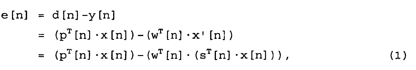
wherein x[n] is the input signal vector at a time n as expressed by
(L is the filter length of W(z))
and p[n] is the filter coefficient vector of P(z) at a time n as expressed by
and s[n] is the filter coefficient vector of S(z) at a time n as expressed by
and w[n] is the filter coefficient vector of W(z) at a time n as expressed by
- The filter coefficient update of w[n] is performed iteratively - i.e., at each time n. The filter is designed in such a way that the filter coefficients w[n] are calculated so that the current squared error e2[n] is minimized. This is normally achieved in practical applications using the LMS (or NLMS) algorithm, which update is referred to as of the coefficient vector w[n] and can be summarized as follows:


where µ is the adaptation step size and x'[n] is the input signal vector previously filtered with S(z) as expressed by
- Using an inverse filter designed directly with the FXLMS algorithm - i.e., without any additional modifications usually creates problems. On the one hand, audible artifacts such as pre-echoes may occur, and on the other hand, an inverse filter at times requires very many filter coefficients, which are not readily available in practical applications.
- As can be seen easily that this is the case as otherwise equalization is only possible to a base limit frequency, which is set lower and lower the longer the inverse filter is. Unfortunately, the human ear can distinguish between frequencies very well, particularly in the spectral domain, which means that humans react very sensitively to spectral errors. It is therefore important that the inverse filter has a high level of spectral resolution, particularly in the lower spectral domain - signifying, however, that the filter has to be long.
- One way of solving this problem, for example, is to use a filter with a non-linear frequency resolution - i.e., one that has high resolution for low frequencies and deteriorating resolution for increasingly higher frequencies. Such filters exist and are referred to as warped, Kautz, or Lagurerre filters, among others. These filters can also be designed as adaptive filters, but they then unfortunately no longer exhibit favorable properties. Consequently, an indirect implementation is preferred - i.e., conversion of a conventional, long adaptive Finite Impulse Response (FIR) filter after its adaptation to a filter with non-linear frequency resolution.
- However, with increasing length, adaptive FIR filters suffer more and more from the occurrence of quantization errors, therefore becoming more and more instable or imprecise, meaning that even their direct implementation causes problems in practical cases. A feasible method of implementing very long adaptive FIR filters in practice is, for example, to design the adaptive filter directly in the spectral domain or in sub-bands - in other words, using a multi-rate system.
- Each of the two approaches has its own particular advantages and disadvantages. One advantage of calculating in the spectral domain is that the efficient Fast Fourier Transformation (FFT) and Inverse Fast Fourier Transformation (IFFT) algorithms can be used for the transition from the time to the frequency domain and in the other direction, and that adaptive filters adapt very quickly and accurately in the spectral domain. The chief disadvantage of the solution is this enormous amount of computing resources it consumes. In contrast, an implementation using a multi-rate system requires considerably less memory, depending on the design, but is either very inaccurate or needs longer computing times. Both solutions can be very easily scaled, though, and can therefore be flexibly adapted to the resources that are available.
- The adaptive filter should - as described earlier - have sufficiently high frequency resolution. For processing in the spectral domain, a correspondingly long FFT has to be used for the transformation from the time to the frequency domain, which necessarily causes a further problem, that of longer signal delays. An implementation in sub-bands according to the invention using a mixture of different signal processing methods can elegantly keep the signal delay to a minimum while at the same time enabling the preferred signal processing method with non-linear frequency resolution to be realized, at least approximately. To do so, the time signal is first split into different frequency bands, which on the one hand reduces the sampling rate, and on the other hand, provides only narrowband time signals. Depending on which spectral domain a narrowband time signal belongs to, it can be processed with a longer or shorter adaptive filter to obtain a differentiated, frequency-dependent spectral resolution. It is advisable to choose the lengths of the corresponding adaptive filters in the sub-bands in such a way that the resulting full frequency resolution approximately matches that of human hearing - i.e., that it roughly follows the Bark frequency scheme.
- A very efficient way of implementing a filter bank in memory and computing time terms is to use a critically sampled poly-phase Quadrature Mirror Filter (QMF) bank consisting of connected Infinite Impulse Response (IIR) all-pass filters in a tree structure. A critically sampled, single-stage poly-phase analysis/synthesis system all-pass filters consisting of connected IIR filters is illustrated in
FIG 2 . - In the filter of
FIG 2 , an input signal x[n] is divided by 2 individer unit 201 and then applied to a sample rate down-converter 202 and via adelay unit 203 to a sample rate down-converter 204. The sample rate down-converters pass filter filter 205 is applied to anadder unit 207 and anadder unit 208. The output offilter 206 is applied to theadder unit 207 and via aninverter 209 to theadder unit 208. Further, the output ofadder unit 207 is applied to anadder unit 210 and anadder unit 211. The output ofadder unit 208 is applied to theadder unit 210 and via aninverter 212 to theadder unit 211.Filters adder units pass filter 212 has the transfer function A1(z) and IIR all-pass filter 213 has the transfer function Ao(z). The output offilter 212 is applied via a sample rate down-converter 214 and a delay unit 215 to an adder unit 217. The output offilter 213 is applied via a sample rate down-converter 216 to the adder unit 217 which provides an output signal y[n] via adivider unit 218 for dividing by 2. - A filter bank with tree structure is obtained by continuous insertion in each case of an analysis/synthesis pair in the signal processing area of the preceding stage.
-
FIG 3 is a signal flow diagram of a 4-stage filter bank with tree structure. Such filter bank comprises 15 analysis filters Fsi ( i = 1...15) and 15 synthesis filters Fmi (i = 1...15). A first analysis stage comprises one analysis filter splitting an input signal x[n] into two signals for two analysis filters in the second stage. The two analysis filters in the second analysis stage generate, accordingly, four signals for the following third analysis stage which comprises four analysis filters. Finally the fourth stage containing eight analysis filters and receiving eight signals from the third stage generates sixteen output signals which are then further processed by signal processing units (not shown in detail inFIG 3 ) for providing sixteen input signals for the first synthesis stage having sixteen synthesis filters for providing eight signals for the second synthesis stage. The second synthesis stage comprises four synthesis filters providing four signals to a third synthesis stage having two synthesis filters. Finally a fourth synthesis stage comprising one synthesis filter provides the output signal y[n]. - Adaptive filters implemented using a critically sampled multi-rate system basically suffer from the problem that adjacent bands overlap each other and that aliasing occurs as a consequence. Although the aliasing can be reduced by steeper transitions between the limiting bandpass filters, it cannot be fully avoided. An oversampled filter bank may alleviate the situation (cf. Jörg Kliewer, "Beiträge zum Entwurf modulierter Filterbänke für verschiedene Teilbandabtastraten" [On designing modulated filter banks for different sub-band sampling rates], PhD thesis, Sharker Publishers, 1999). Depending on the sampling rate used, the filter bank in some cases needs significantly greater computing resources, which is not regarded as such a big drawback in view of the enormous efficiency of the implementation. Moreover, no implementation of an oversampled filter bank using the uncomplicated, connected IIR all-pass filters is known, meaning that an implementation with FIR filters has to be used, which however increases the memory requirements to a major extent. In the present case, it is for the most part irrelevant whether the IIR filter bank is realized using a multi-complementary, modulated or poly-phase filter bank.
- With reference to
FIG 4 , an example showing the effects of aliasing errors in the approximation of an unknown system using a sub-band adaptive filter with a critically sampled 4-stage poly-phase filter bank with tree structure is discussed. The length of the corresponding adaptive filters in the 16 bands is defined in each case as L=128. - As can be seen from
FIG 4 , the approximated model only differs notably from the original at the individual band limits. Regarded overall, the errors remain within acceptable limits. - However, it is not important how the aliasing errors behave during the approximation with the original, but rather their inverse behavior. For this reason, the previous example is used again, but this time an adaptive filter is arranged in each sub-band, which is no longer iterated using the NLMS algorithm, but instead the inverse model of the original is approximated using the FXNLMS algorithm.
-
FIG 5 is a diagram illustrating the performance of a 16-band, critically sampled, inverse sub-band adaptive filter. FromFIG 5 , it can be seen that the band limits of the individual sub-bands can no longer be clearly localized - i.e., during approximation of the inverse original transfer function the aliasing errors appear to be less critical than for the approximation of the original transfer function as shown inFIG 4 . - In order to keep the associated errors within limits, an oversampled filter bank is preferred if a filter bank is to be used. The figures shown above are intended to illustrate that considerable savings in resources (computing time as well as memory) can be achieved if certain errors are permitted to be accepted.
- In the two previous illustrations, an adaptive filter with the same length was used for each sub-band. The length was selected in such a way that a sufficiently high frequency resolution was obtained in the lower frequency domain. As already explained, this resolution performance is not required for the upper frequency domain owing to the frequency resolution characteristics of the human ear. Consequently, the lengths of the adaptive filters for the upper sub-bands decrease steadily with increasing frequency. A filter bank designed as outlined above in which the lengths of the individual adaptive sub-band filters are adapted to the Bark frequency response exhibit performance corresponding to that shown later in
FIG 6 . -
FIG 5 illustrates the performance of a 16-band, critically sampled, inverse sub-band adaptive filter. When determining the inverse filter, a target frequency response can be specified. The adaptation algorithm attempts to produce the inverse filter in such a way that a chain circuit of the same filter with the original transfer function matches the specified target transfer function. What is also known is that the target function should be oriented approximately with the mean power spectral density of the noise signal. Low-frequency noise signals dominate in automobiles, implying that a target transfer function such as shown inFIG 7 below can be specified. - Due to the logarithmic representation of
Figure 7 , it is not immediately evident that the phases of the target transfer function are linear. Other than that, one can see that the function falls continuously with increasing frequency, which mainly also corresponds to the typical impulse response of the interior of an automobile. Maintaining the target function at a constant value from a specific base limit frequency on would indubitably cause an enormous rise in the upper frequency domain. By selecting the target transfer function shown above the rise in the function remains generally moderate, even in the upper frequency domain. This is illustrated in the example ofFIG 8 which shows the performance of a 16-band, critically sampled, inverse sub-band adaptive filter approximating a specified target transfer function. As can be seen fromFIG 8 , the convolution of the original impulse response with that of the approximated inverse filter mainly closely matches the specified target transfer function without the need for strong increases in the upper frequency domain. - A minimum phase transfer function can be easily inverted fully in a direct way. However, the all-pass splitting (which is needed to isolate the minimum phase component in a maximum phase system) is difficult to be accomplished, at least not in real time. The minimum phase component of the transfer function alone can be iteratively determined directly using the Linear Predictive Coding (LPC) coefficients. An efficient method of calculating the LPC coefficients is provided by the Gradient Adaptive Lattice (GAL) algorithm. Using this algorithm, any number of LPC coefficients can be iteratively computed without the need of the complex Levinson-Durbin recursion.
- The filter structure with which the GAL algorithm can be realized may be an Adaptive Lattice Predictor (ALP) structure. An example for an Adaptive Lattice Predictor (ALP) 4th order filter is shown in
FIG 9 , in which the signal n~[k] to be filtered is split into a signal f0[k] and a signal b0[k]. Signal f0[k] is applied to asubtraction unit 21 and to amultiplier unit 22 where it is multiplied by a constant factor K1. The signal output ofmultiplier unit 22 is applied to asubtraction unit 23 which further receives a signal from adelay unit 24 for delaying the signal b0[k]. The delayed signal b0[k] is also supplied to amultiplier unit 25 where it is multiplied by the constant factor K1. The signal output ofmultiplier unit 25 is applied tosubtraction unit 21 which outputs a signal f1[k] whilesubtraction unit 23 outputs a signal b1[k].Subtraction units multipliers unit 24 form a first Lattice stage which is followed by two further Lattice stages. Accordingly, signals f1[k], b1[k] are applied to the second stage outputting signals f2[k], b2[k], which are applied to the third stage outputting signals f3[k], b3[k] as output signals of theALP 4th order filter. The second and third Lattice stage comprise subtraction units 21', 23', multipliers 22', 25', delay unit 24' or subtraction units 21'', 23'', multipliers 22'', 25'', delay unit 24'', respectively, wherein all three stages have the same circuit structure. - The ALP filter reproduces the minimum phase part of the unknown transfer function. The LPC coefficients of the ALP filter (K1, ..., KN-1) are calculated iteratively using the GAL algorithm.

- To invert the minimum phase component of the unknown transfer function, the LPC coefficients calculated using the GAL algorithm can be directly inserted, for example, in a Lattice all-pole filter. Such Lattice all-
pole 4th order filter is illustrated inFIG 10 . In the filter shown inFIG. 10 , in which signal f3[k] forms an input signal x[k] that is applied to asubtraction unit 31, whereinsubtraction unit 31 also receives a signal from adelay unit 34 via amultiplier unit 32 multiplying it by a constant factor K3. Subtraction unit 31 outputs the signal f2[k] which is also applied via amultiplier unit 35 for multiplying it by factor K3 to asubtraction unit 33 which further receives the signal b2[k] delayed bydelay unit 34.Subtraction units multipliers unit 34 form a first Lattice stage which is followed by two further Lattice stages. The second and third Lattice stage comprise subtraction units 31', 33', multipliers 32', 35', delay unit 34' or subtraction units 31'', 33'', multipliers 32'', 35'', delay unit 34'', respectively, wherein all three stages have the same circuit structure. Accordingly, signals f3[k], b2[k] are applied to the first stage outputting signals f2[k] and b3[k]. Signals f2[k] and b1[k] are applied to the second stage outputting signals f1[k] and b2[k]. Signals f1[k] and b0[k] are applied to the third stage outputting signals f0[k] and b1[k]. Signal f0[k] serves as signal b0[k] and as output signal y[k] of the Lattice all-pole 4th order filter. - However, the direct use of the LPC coefficients is only advisable under specific conditions, namely provided sufficient computing time is available depending on the Digital Signal Processor (DSP) used. Lattice filters may require considerably greater computing power on one hand, but on the other hand it may be used as a low-noise, dynamic filter structure, due to their symmetrical structure, lattice filters produce only minimal quantization noise. Otherwise, the use of a simple IIR-only filter - e.g., in direct form - is the preferred method since it is generally much easier to implement and more efficient in its application. However, to use a simple IIR filter, the LPC (reflection) filter coefficients must first be converted to their appropriate direct form. They can then be further transformed if required into warped filter coefficients, for example.
- Direct, broadband use of the GAL algorithm is possible, but requires a lot of computing time and, similar to the adaptive FIR filter, also suffers from quantization problems if long lengths are used. The direct use of a warped GAL algorithm also experienced the same weaknesses as the direct use of the adaptive warped FIR filter.
- A very efficient application of the GAL algorithm is to embed it in a multi-rate signal processing system. Then, for example, the inverse of the minimum phase component of the unknown transfer function could be directly determined in each sub-band, and converted using the Lattice all-pole filter shown previously. A direct implementation in this case would only moderately extend the computing time since - for a multi-rate system - the complex filters are operated in the undersampled domain. The performance of a 16-band, critically sampled, inverse sub-band adaptive GAL filter with approximated Bark frequency response is shown in
FIG 11 . - Although various exemplary embodiments of the invention have been disclosed, it will be apparent to those skilled in the art that various changes and modifications can be made which will achieve some of the advantages of the invention without departing from the scope of the invention as defined by the appended claims. It will be obvious to those reasonably skilled in the art that other components performing the same functions may be suitably substituted. Further, the methods of the invention may be achieved in either all software implementations, using the appropriate processor instructions, or in hybrid implementations that utilize a combination of hardware logic and software logic to achieve the same results.
Claims (19)
- Audio enhancement system for compensating for linear distortions of a sound signal (x[n]) reproduced by an audio system in a listening room; said audio enhancement system comprising:an analysis filter bank having a plurality of analysis sub-filters (205, 206) and receiving an audio signal to be enhanced and generating a number of analysis output signals corresponding to different frequency ranges of the input signal;a synthesis filter bank having a plurality of synthesis sub-filters (212, 213) and generating an enhanced audio signal from a number of synthesis input signals; wherein said number of analysis output signals and said number of synthesis input signals are identical and at least two; anda processing unit connected between the analysis filter bank and the synthesis filter bank and comprising a number of adaptive sub-band filters; wherein each of said adaptive sub-band filters receives one of the analysis output signals, and each generates one of the synthesis input signals; the adaptive sub-band filters forming an inverse filter for equalizing an unknown transfer function established by the audio system and the listening room such that the unknown transfer function complies with a specific target function (P(z)) within the respective frequency range,characterized in that each filter bank is a poly-phase Quadrature Mirror Filter (QMF) bank consisting of connected Infinite Impulse Response (IIR) all-pass filters as sub-band filters in a tree structure.
- The audio enhancement system of claim 1 wherein at least one adaptive sub-band filter involves a Least Mean Square algorithm.
- The audio enhancement system of claim 2 wherein the at least one adaptive sub-band filter comprises
a first partial system receiving an analysis output signal as an reference signal and having a reference transfer function, and
a second partial system established by the audio system and the listening room having an unknown transfer function, wherein
the second partial system outputs a filtered reference signal that is supplied to an adaptive Least Mean Square filter,
said adaptive Least Mean Square filter receives the filtered reference signal and an error signal to control its filter coefficients; said error signal being provided by subtracting from the filtered reference signal a signal output by the adaptive Least Mean Square filter. - The audio enhancement system of one of claims 1 to 3 wherein the filter banks have a non-linear frequency resolution.
- The audio enhancement system of claim 4 wherein the lengths of the individual adaptive sub-band filters are adapted to said non-linear frequency resolution.
- The audio enhancement system of claim 4 or 5 wherein the non-linear frequency resolution is adapted to the Bark scale.
- The audio enhancement system of one of claims 1 to 6 wherein the analysis filter bank comprises multiple analysis sub-filters arranged in a tree structure; each one of said analysis sub-band filters splitting one input signal into at least two output signals.
- The audio enhancement system of one of claims 1 to 7 wherein the synthesis filter bank comprises multiple synthesis sub-band filters arranged in a tree structure; each one of said synthesis sub-band filters combining at least two input signals into one output signal.
- The audio enhancement system of one of claims 1 to 8 wherein the analysis and synthesis sub-band filters are operated at a critical sample rate.
- The audio enhancement system of one of claims 1 to 8 wherein the analysis and synthesis sub-band filters are operated at an over-sampling sample rate.
- Audio enhancement method for compensating for linear distortions of a sound signal (x[n]) reproduced by an audio system in a listening room; said audio enhancement method comprising:an analysis filtering step for generating in sub-bands corresponding to different frequency ranges a number of analysis output signals from an audio signal to be enhanced;a synthesis filtering step for generating an enhanced audio signal from a number of synthesis input signals; wherein said number of analysis output signals and said number of synthesis input signals are identical and at least two; anda processing step between the analysis filtering step and the synthesis filtering step for generating one of the synthesis input signals from a respective one of the analysis output signals in order to perform an inverse filtering for equalizing an unknown transfer function established by the audio system and the listening room such that the unknown transfer function complies with a specific target function (P(z)) within the respective frequency range,characterized in that each filtering step comprises a poly-phase Quadrature Mirror Filtering (QMF) using connected Infinite Impulse Response (IIR) all-pass filters as sub-band filters in a tree structure.
- The audio enhancement method of claim 11 wherein the processing step involves a Least Mean Square algorithm.
- The audio enhancement method of claim 12 wherein the processing step comprises
a first partial filtering step including receiving an analysis output signal as an reference signal and processing the reference signal with a reference transfer function, and
a second partial filtering step performed by the audio system and the listening room with an unknown transfer function, wherein
the second partial filtering step outputs a filtered reference signal that is supplied to an adaptive Least Mean Square filtering step,
said adaptive Least Mean Square filtering step receives the filtered reference signal and an error signal to control its filtering; said error signal being provided by subtracting from the filtered reference signal a signal output by the adaptive Least Mean Square filter. - The audio enhancement method of one of claims 11 to 13 wherein the filtering steps have a non-linear frequency resolution.
- The audio enhancement method of claim 14 wherein the lengths of the individual adaptive filtering steps are adapted to said non-linear frequency resolution.
- The audio enhancement method of claim 14 or 15 wherein the non-linear frequency resolution is adapted to the Bark scale.
- The audio enhancement method of one of claims 11 to 16 wherein the filtering steps comprise multiple sub-band filtering steps performed in according to a tree structure; each one of said sub-band filtering steps splitting one input signal into at least two output signals.
- The audio enhancement method of one of claims 14 to 17 wherein the filtering steps are performed at a critical sample rate.
- The audio enhancement method of one of claims 14 to 18 wherein the filtering steps are performed at an over-sampling sample rate.
Priority Applications (2)
| Application Number | Priority Date | Filing Date | Title |
|---|---|---|---|
| EP05010513.9A EP1722360B1 (en) | 2005-05-13 | 2005-05-13 | Audio enhancement system and method |
| US11/434,496 US7881482B2 (en) | 2005-05-13 | 2006-05-15 | Audio enhancement system |
Applications Claiming Priority (1)
| Application Number | Priority Date | Filing Date | Title |
|---|---|---|---|
| EP05010513.9A EP1722360B1 (en) | 2005-05-13 | 2005-05-13 | Audio enhancement system and method |
Publications (2)
| Publication Number | Publication Date |
|---|---|
| EP1722360A1 EP1722360A1 (en) | 2006-11-15 |
| EP1722360B1 true EP1722360B1 (en) | 2014-03-19 |
Family
ID=35610040
Family Applications (1)
| Application Number | Title | Priority Date | Filing Date |
|---|---|---|---|
| EP05010513.9A Active EP1722360B1 (en) | 2005-05-13 | 2005-05-13 | Audio enhancement system and method |
Country Status (2)
| Country | Link |
|---|---|
| US (1) | US7881482B2 (en) |
| EP (1) | EP1722360B1 (en) |
Families Citing this family (11)
| Publication number | Priority date | Publication date | Assignee | Title |
|---|---|---|---|---|
| EP2051543B1 (en) * | 2007-09-27 | 2011-07-27 | Harman Becker Automotive Systems GmbH | Automatic bass management |
| JP4506873B2 (en) * | 2008-05-08 | 2010-07-21 | ソニー株式会社 | Signal processing apparatus and signal processing method |
| WO2011047887A1 (en) * | 2009-10-21 | 2011-04-28 | Dolby International Ab | Oversampling in a combined transposer filter bank |
| US8718290B2 (en) | 2010-01-26 | 2014-05-06 | Audience, Inc. | Adaptive noise reduction using level cues |
| US9378754B1 (en) | 2010-04-28 | 2016-06-28 | Knowles Electronics, Llc | Adaptive spatial classifier for multi-microphone systems |
| US8958510B1 (en) * | 2010-06-10 | 2015-02-17 | Fredric J. Harris | Selectable bandwidth filter |
| AU2011312135A1 (en) | 2010-10-07 | 2013-05-30 | Concertsonics, Llc | Method and system for enhancing sound |
| US9031268B2 (en) * | 2011-05-09 | 2015-05-12 | Dts, Inc. | Room characterization and correction for multi-channel audio |
| MX347316B (en) | 2013-01-29 | 2017-04-21 | Fraunhofer Ges Forschung | Apparatus and method for synthesizing an audio signal, decoder, encoder, system and computer program. |
| US10414337B2 (en) | 2013-11-19 | 2019-09-17 | Harman International Industries, Inc. | Apparatus for providing environmental noise compensation for a synthesized vehicle sound |
| CN110191396B (en) * | 2019-05-24 | 2022-05-27 | 腾讯音乐娱乐科技(深圳)有限公司 | Audio processing method, device, terminal and computer readable storage medium |
Family Cites Families (22)
| Publication number | Priority date | Publication date | Assignee | Title |
|---|---|---|---|---|
| US4118601A (en) * | 1976-11-24 | 1978-10-03 | Audio Developments International | System and a method for equalizing an audio sound transducer system |
| US4306113A (en) * | 1979-11-23 | 1981-12-15 | Morton Roger R A | Method and equalization of home audio systems |
| US4340780A (en) * | 1980-03-07 | 1982-07-20 | Transcale Ab | Self-correcting audio equalizer |
| NL8401823A (en) * | 1984-06-08 | 1986-01-02 | Philips Nv | DEVICE FOR CONVERTING AN ELECTRIC SIGNAL TO AN ACOUSTIC SIGNAL OR REVERSE AND A NON-LINEAR NETWORK FOR USE IN THE DEVICE. |
| US4823391A (en) * | 1986-07-22 | 1989-04-18 | Schwartz David M | Sound reproduction system |
| US4910779A (en) * | 1987-10-15 | 1990-03-20 | Cooper Duane H | Head diffraction compensated stereo system with optimal equalization |
| US4975954A (en) * | 1987-10-15 | 1990-12-04 | Cooper Duane H | Head diffraction compensated stereo system with optimal equalization |
| US5034983A (en) * | 1987-10-15 | 1991-07-23 | Cooper Duane H | Head diffraction compensated stereo system |
| US5136651A (en) * | 1987-10-15 | 1992-08-04 | Cooper Duane H | Head diffraction compensated stereo system |
| US4893342A (en) * | 1987-10-15 | 1990-01-09 | Cooper Duane H | Head diffraction compensated stereo system |
| US6252909B1 (en) * | 1992-09-21 | 2001-06-26 | Aware, Inc. | Multi-carrier transmission system utilizing channels of different bandwidth |
| US6760451B1 (en) * | 1993-08-03 | 2004-07-06 | Peter Graham Craven | Compensating filters |
| DE4332804C2 (en) * | 1993-09-27 | 1997-06-05 | Klippel Wolfgang | Adaptive correction circuit for electroacoustic sound transmitters |
| DE4419819A1 (en) | 1994-06-07 | 1995-12-14 | Spang Linda Dipl Ing | Audio frequency filter and method for determining the filter function of an audio frequency filter |
| US5680450A (en) * | 1995-02-24 | 1997-10-21 | Ericsson Inc. | Apparatus and method for canceling acoustic echoes including non-linear distortions in loudspeaker telephones |
| US5852667A (en) * | 1995-07-03 | 1998-12-22 | Pan; Jianhua | Digital feed-forward active noise control system |
| DE10027618B4 (en) | 1999-06-19 | 2013-11-14 | Ascendo Gmbh | transducer |
| JP4639441B2 (en) * | 1999-09-01 | 2011-02-23 | ソニー株式会社 | Digital signal processing apparatus and processing method, and digital signal recording apparatus and recording method |
| SE0001926D0 (en) * | 2000-05-23 | 2000-05-23 | Lars Liljeryd | Improved spectral translation / folding in the subband domain |
| GB0100444D0 (en) | 2001-01-09 | 2001-02-21 | Roke Manor Research | Improvements in or relating to hi-fi audio systems |
| EP1516514A1 (en) * | 2002-06-12 | 2005-03-23 | Equtech APS | Method of digital equalisation of a sound from loudspeakers in rooms and use of the method |
| US20050271216A1 (en) * | 2004-06-04 | 2005-12-08 | Khosrow Lashkari | Method and apparatus for loudspeaker equalization |
-
2005
- 2005-05-13 EP EP05010513.9A patent/EP1722360B1/en active Active
-
2006
- 2006-05-15 US US11/434,496 patent/US7881482B2/en active Active
Also Published As
| Publication number | Publication date |
|---|---|
| US20060259531A1 (en) | 2006-11-16 |
| US7881482B2 (en) | 2011-02-01 |
| EP1722360A1 (en) | 2006-11-15 |
Similar Documents
| Publication | Publication Date | Title |
|---|---|---|
| EP1722360B1 (en) | Audio enhancement system and method | |
| US9754597B2 (en) | Alias-free subband processing | |
| US5272656A (en) | System and method of producing adaptive FIR digital filter with non-linear frequency resolution | |
| EP2530840B1 (en) | Efficient sub-band adaptive FIR-filtering | |
| KR100859348B1 (en) | Dynamic range control and equalization of digital audio using warped processing | |
| US7818079B2 (en) | Equalization based on digital signal processing in downsampled domains | |
| US7602925B2 (en) | Audio feedback processing system | |
| KR100312636B1 (en) | Compensation Filter | |
| US8077880B2 (en) | Combined multirate-based and fir-based filtering technique for room acoustic equalization | |
| US9148126B2 (en) | Sub-band signal processing | |
| EP2667508B1 (en) | Method and apparatus for efficient frequency-domain implementation of time-varying filters | |
| CN101207939A (en) | Low complexity echo compensation | |
| US20060153404A1 (en) | Parametric equalizer method and system | |
| US5805715A (en) | Method and apparatus for compensating multi-resolution linear distortion | |
| US20060177074A1 (en) | Early reflection reproduction apparatus and method of sound field effect reproduction | |
| WO2011027215A1 (en) | Method and apparatus for processing audio signals | |
| US6252968B1 (en) | Acoustic quality enhancement via feedback and equalization for mobile multimedia systems | |
| Vary | An adaptive filter-bank equalizer for speech enhancement | |
| US7263542B2 (en) | Inverse filtering method, synthesis filtering method, inverse filter device, synthesis filter device and devices comprising such filter devices | |
| JP2001358561A (en) | Sampling rate converting apparatus | |
| WO1992005501A1 (en) | System and method of producing adaptive fir digital filter with non-linear frequency resolution | |
| JPH04185017A (en) | Quantization error reducing device for audio signal |
Legal Events
| Date | Code | Title | Description |
|---|---|---|---|
| PUAI | Public reference made under article 153(3) epc to a published international application that has entered the european phase |
Free format text: ORIGINAL CODE: 0009012 |
|
| AK | Designated contracting states |
Kind code of ref document: A1 Designated state(s): AT BE BG CH CY CZ DE DK EE ES FI FR GB GR HU IE IS IT LI LT LU MC NL PL PT RO SE SI SK TR |
|
| AX | Request for extension of the european patent |
Extension state: AL BA HR LV MK YU |
|
| 17P | Request for examination filed |
Effective date: 20070419 |
|
| AKX | Designation fees paid |
Designated state(s): AT BE BG CH CY CZ DE DK EE ES FI FR GB GR HU IE IS IT LI LT LU MC NL PL PT RO SE SI SK TR |
|
| 17Q | First examination report despatched |
Effective date: 20100121 |
|
| GRAP | Despatch of communication of intention to grant a patent |
Free format text: ORIGINAL CODE: EPIDOSNIGR1 |
|
| INTG | Intention to grant announced |
Effective date: 20140109 |
|
| GRAS | Grant fee paid |
Free format text: ORIGINAL CODE: EPIDOSNIGR3 |
|
| GRAA | (expected) grant |
Free format text: ORIGINAL CODE: 0009210 |
|
| AK | Designated contracting states |
Kind code of ref document: B1 Designated state(s): AT BE BG CH CY CZ DE DK EE ES FI FR GB GR HU IE IS IT LI LT LU MC NL PL PT RO SE SI SK TR |
|
| REG | Reference to a national code |
Ref country code: GB Ref legal event code: FG4D |
|
| REG | Reference to a national code |
Ref country code: CH Ref legal event code: EP |
|
| REG | Reference to a national code |
Ref country code: IE Ref legal event code: FG4D |
|
| REG | Reference to a national code |
Ref country code: AT Ref legal event code: REF Ref document number: 658117 Country of ref document: AT Kind code of ref document: T Effective date: 20140415 |
|
| REG | Reference to a national code |
Ref country code: DE Ref legal event code: R096 Ref document number: 602005042989 Country of ref document: DE Effective date: 20140430 |
|
| PG25 | Lapsed in a contracting state [announced via postgrant information from national office to epo] |
Ref country code: LT Free format text: LAPSE BECAUSE OF FAILURE TO SUBMIT A TRANSLATION OF THE DESCRIPTION OR TO PAY THE FEE WITHIN THE PRESCRIBED TIME-LIMIT Effective date: 20140319 |
|
| REG | Reference to a national code |
Ref country code: NL Ref legal event code: VDEP Effective date: 20140319 |
|
| REG | Reference to a national code |
Ref country code: AT Ref legal event code: MK05 Ref document number: 658117 Country of ref document: AT Kind code of ref document: T Effective date: 20140319 |
|
| REG | Reference to a national code |
Ref country code: LT Ref legal event code: MG4D |
|
| PG25 | Lapsed in a contracting state [announced via postgrant information from national office to epo] |
Ref country code: SE Free format text: LAPSE BECAUSE OF FAILURE TO SUBMIT A TRANSLATION OF THE DESCRIPTION OR TO PAY THE FEE WITHIN THE PRESCRIBED TIME-LIMIT Effective date: 20140319 Ref country code: CY Free format text: LAPSE BECAUSE OF FAILURE TO SUBMIT A TRANSLATION OF THE DESCRIPTION OR TO PAY THE FEE WITHIN THE PRESCRIBED TIME-LIMIT Effective date: 20140319 Ref country code: FI Free format text: LAPSE BECAUSE OF FAILURE TO SUBMIT A TRANSLATION OF THE DESCRIPTION OR TO PAY THE FEE WITHIN THE PRESCRIBED TIME-LIMIT Effective date: 20140319 |
|
| PG25 | Lapsed in a contracting state [announced via postgrant information from national office to epo] |
Ref country code: BE Free format text: LAPSE BECAUSE OF FAILURE TO SUBMIT A TRANSLATION OF THE DESCRIPTION OR TO PAY THE FEE WITHIN THE PRESCRIBED TIME-LIMIT Effective date: 20140319 Ref country code: RO Free format text: LAPSE BECAUSE OF FAILURE TO SUBMIT A TRANSLATION OF THE DESCRIPTION OR TO PAY THE FEE WITHIN THE PRESCRIBED TIME-LIMIT Effective date: 20140319 Ref country code: NL Free format text: LAPSE BECAUSE OF FAILURE TO SUBMIT A TRANSLATION OF THE DESCRIPTION OR TO PAY THE FEE WITHIN THE PRESCRIBED TIME-LIMIT Effective date: 20140319 Ref country code: EE Free format text: LAPSE BECAUSE OF FAILURE TO SUBMIT A TRANSLATION OF THE DESCRIPTION OR TO PAY THE FEE WITHIN THE PRESCRIBED TIME-LIMIT Effective date: 20140319 Ref country code: BG Free format text: LAPSE BECAUSE OF FAILURE TO SUBMIT A TRANSLATION OF THE DESCRIPTION OR TO PAY THE FEE WITHIN THE PRESCRIBED TIME-LIMIT Effective date: 20140619 Ref country code: IS Free format text: LAPSE BECAUSE OF FAILURE TO SUBMIT A TRANSLATION OF THE DESCRIPTION OR TO PAY THE FEE WITHIN THE PRESCRIBED TIME-LIMIT Effective date: 20140719 Ref country code: CZ Free format text: LAPSE BECAUSE OF FAILURE TO SUBMIT A TRANSLATION OF THE DESCRIPTION OR TO PAY THE FEE WITHIN THE PRESCRIBED TIME-LIMIT Effective date: 20140319 |
|
| PG25 | Lapsed in a contracting state [announced via postgrant information from national office to epo] |
Ref country code: AT Free format text: LAPSE BECAUSE OF FAILURE TO SUBMIT A TRANSLATION OF THE DESCRIPTION OR TO PAY THE FEE WITHIN THE PRESCRIBED TIME-LIMIT Effective date: 20140319 Ref country code: SK Free format text: LAPSE BECAUSE OF FAILURE TO SUBMIT A TRANSLATION OF THE DESCRIPTION OR TO PAY THE FEE WITHIN THE PRESCRIBED TIME-LIMIT Effective date: 20140319 Ref country code: ES Free format text: LAPSE BECAUSE OF FAILURE TO SUBMIT A TRANSLATION OF THE DESCRIPTION OR TO PAY THE FEE WITHIN THE PRESCRIBED TIME-LIMIT Effective date: 20140319 Ref country code: PL Free format text: LAPSE BECAUSE OF FAILURE TO SUBMIT A TRANSLATION OF THE DESCRIPTION OR TO PAY THE FEE WITHIN THE PRESCRIBED TIME-LIMIT Effective date: 20140319 |
|
| REG | Reference to a national code |
Ref country code: DE Ref legal event code: R097 Ref document number: 602005042989 Country of ref document: DE |
|
| PG25 | Lapsed in a contracting state [announced via postgrant information from national office to epo] |
Ref country code: LU Free format text: LAPSE BECAUSE OF FAILURE TO SUBMIT A TRANSLATION OF THE DESCRIPTION OR TO PAY THE FEE WITHIN THE PRESCRIBED TIME-LIMIT Effective date: 20140513 Ref country code: PT Free format text: LAPSE BECAUSE OF FAILURE TO SUBMIT A TRANSLATION OF THE DESCRIPTION OR TO PAY THE FEE WITHIN THE PRESCRIBED TIME-LIMIT Effective date: 20140721 |
|
| REG | Reference to a national code |
Ref country code: CH Ref legal event code: PL |
|
| PLBE | No opposition filed within time limit |
Free format text: ORIGINAL CODE: 0009261 |
|
| STAA | Information on the status of an ep patent application or granted ep patent |
Free format text: STATUS: NO OPPOSITION FILED WITHIN TIME LIMIT |
|
| PG25 | Lapsed in a contracting state [announced via postgrant information from national office to epo] |
Ref country code: LI Free format text: LAPSE BECAUSE OF NON-PAYMENT OF DUE FEES Effective date: 20140531 Ref country code: MC Free format text: LAPSE BECAUSE OF FAILURE TO SUBMIT A TRANSLATION OF THE DESCRIPTION OR TO PAY THE FEE WITHIN THE PRESCRIBED TIME-LIMIT Effective date: 20140319 Ref country code: DK Free format text: LAPSE BECAUSE OF FAILURE TO SUBMIT A TRANSLATION OF THE DESCRIPTION OR TO PAY THE FEE WITHIN THE PRESCRIBED TIME-LIMIT Effective date: 20140319 Ref country code: CH Free format text: LAPSE BECAUSE OF NON-PAYMENT OF DUE FEES Effective date: 20140531 |
|
| 26N | No opposition filed |
Effective date: 20141222 |
|
| REG | Reference to a national code |
Ref country code: IE Ref legal event code: MM4A |
|
| PG25 | Lapsed in a contracting state [announced via postgrant information from national office to epo] |
Ref country code: IT Free format text: LAPSE BECAUSE OF FAILURE TO SUBMIT A TRANSLATION OF THE DESCRIPTION OR TO PAY THE FEE WITHIN THE PRESCRIBED TIME-LIMIT Effective date: 20140319 |
|
| REG | Reference to a national code |
Ref country code: DE Ref legal event code: R097 Ref document number: 602005042989 Country of ref document: DE Effective date: 20141222 |
|
| PG25 | Lapsed in a contracting state [announced via postgrant information from national office to epo] |
Ref country code: IE Free format text: LAPSE BECAUSE OF NON-PAYMENT OF DUE FEES Effective date: 20140513 |
|
| REG | Reference to a national code |
Ref country code: FR Ref legal event code: PLFP Year of fee payment: 11 |
|
| PG25 | Lapsed in a contracting state [announced via postgrant information from national office to epo] |
Ref country code: SI Free format text: LAPSE BECAUSE OF FAILURE TO SUBMIT A TRANSLATION OF THE DESCRIPTION OR TO PAY THE FEE WITHIN THE PRESCRIBED TIME-LIMIT Effective date: 20140319 |
|
| PGFP | Annual fee paid to national office [announced via postgrant information from national office to epo] |
Ref country code: FR Payment date: 20150519 Year of fee payment: 11 |
|
| PG25 | Lapsed in a contracting state [announced via postgrant information from national office to epo] |
Ref country code: GR Free format text: LAPSE BECAUSE OF FAILURE TO SUBMIT A TRANSLATION OF THE DESCRIPTION OR TO PAY THE FEE WITHIN THE PRESCRIBED TIME-LIMIT Effective date: 20140620 |
|
| PG25 | Lapsed in a contracting state [announced via postgrant information from national office to epo] |
Ref country code: TR Free format text: LAPSE BECAUSE OF FAILURE TO SUBMIT A TRANSLATION OF THE DESCRIPTION OR TO PAY THE FEE WITHIN THE PRESCRIBED TIME-LIMIT Effective date: 20140319 Ref country code: HU Free format text: LAPSE BECAUSE OF FAILURE TO SUBMIT A TRANSLATION OF THE DESCRIPTION OR TO PAY THE FEE WITHIN THE PRESCRIBED TIME-LIMIT; INVALID AB INITIO Effective date: 20050513 |
|
| REG | Reference to a national code |
Ref country code: FR Ref legal event code: ST Effective date: 20170131 |
|
| PG25 | Lapsed in a contracting state [announced via postgrant information from national office to epo] |
Ref country code: FR Free format text: LAPSE BECAUSE OF NON-PAYMENT OF DUE FEES Effective date: 20160531 |
|
| P01 | Opt-out of the competence of the unified patent court (upc) registered |
Effective date: 20230526 |
|
| PGFP | Annual fee paid to national office [announced via postgrant information from national office to epo] |
Ref country code: DE Payment date: 20230419 Year of fee payment: 19 |
|
| PGFP | Annual fee paid to national office [announced via postgrant information from national office to epo] |
Ref country code: GB Payment date: 20230420 Year of fee payment: 19 |