EP1737385B1 - Removable vena cava filter with anchoring feature for reduced trauma - Google Patents
Removable vena cava filter with anchoring feature for reduced trauma Download PDFInfo
- Publication number
- EP1737385B1 EP1737385B1 EP05738517A EP05738517A EP1737385B1 EP 1737385 B1 EP1737385 B1 EP 1737385B1 EP 05738517 A EP05738517 A EP 05738517A EP 05738517 A EP05738517 A EP 05738517A EP 1737385 B1 EP1737385 B1 EP 1737385B1
- Authority
- EP
- European Patent Office
- Prior art keywords
- filter
- struts
- strut
- longitudinal axis
- primary
- Prior art date
- Legal status (The legal status is an assumption and is not a legal conclusion. Google has not performed a legal analysis and makes no representation as to the accuracy of the status listed.)
- Active
Links
- 238000004873 anchoring Methods 0.000 title claims abstract description 58
- 208000014674 injury Diseases 0.000 title description 4
- 230000008733 trauma Effects 0.000 title description 4
- 210000004204 blood vessel Anatomy 0.000 claims abstract description 41
- 239000000463 material Substances 0.000 claims description 15
- 230000017531 blood circulation Effects 0.000 claims description 10
- 230000007704 transition Effects 0.000 claims description 8
- 230000005012 migration Effects 0.000 claims description 5
- 238000013508 migration Methods 0.000 claims description 5
- HLXZNVUGXRDIFK-UHFFFAOYSA-N nickel titanium Chemical compound [Ti].[Ti].[Ti].[Ti].[Ti].[Ti].[Ti].[Ti].[Ti].[Ti].[Ti].[Ni].[Ni].[Ni].[Ni].[Ni].[Ni].[Ni].[Ni].[Ni].[Ni].[Ni].[Ni].[Ni].[Ni] HLXZNVUGXRDIFK-UHFFFAOYSA-N 0.000 claims description 5
- 229910001000 nickel titanium Inorganic materials 0.000 claims description 5
- 229910045601 alloy Inorganic materials 0.000 claims description 4
- 239000000956 alloy Substances 0.000 claims description 4
- 229910001285 shape-memory alloy Inorganic materials 0.000 claims description 4
- 229910000684 Cobalt-chrome Inorganic materials 0.000 claims description 2
- 229910000640 Fe alloy Inorganic materials 0.000 claims description 2
- IUXLMVJVLRVTOH-UHFFFAOYSA-N chromium cobalt iron molybdenum nickel Chemical compound [Cr].[Fe].[Co].[Ni].[Mo] IUXLMVJVLRVTOH-UHFFFAOYSA-N 0.000 claims description 2
- 239000010952 cobalt-chrome Substances 0.000 claims description 2
- 229910001220 stainless steel Inorganic materials 0.000 claims description 2
- 210000001631 vena cava inferior Anatomy 0.000 description 8
- 210000004731 jugular vein Anatomy 0.000 description 7
- 238000001914 filtration Methods 0.000 description 6
- 238000000034 method Methods 0.000 description 6
- 239000008280 blood Substances 0.000 description 5
- 210000004369 blood Anatomy 0.000 description 5
- 230000006870 function Effects 0.000 description 5
- 210000005166 vasculature Anatomy 0.000 description 5
- 208000010378 Pulmonary Embolism Diseases 0.000 description 4
- 230000036760 body temperature Effects 0.000 description 4
- 210000003191 femoral vein Anatomy 0.000 description 4
- 210000003111 iliac vein Anatomy 0.000 description 4
- 230000003902 lesion Effects 0.000 description 4
- 210000002796 renal vein Anatomy 0.000 description 4
- 208000007536 Thrombosis Diseases 0.000 description 3
- 229910001566 austenite Inorganic materials 0.000 description 3
- 230000008901 benefit Effects 0.000 description 3
- 210000004072 lung Anatomy 0.000 description 3
- 229910000734 martensite Inorganic materials 0.000 description 3
- 238000007790 scraping Methods 0.000 description 3
- 238000006748 scratching Methods 0.000 description 3
- 230000002393 scratching effect Effects 0.000 description 3
- 239000010936 titanium Substances 0.000 description 3
- 238000005275 alloying Methods 0.000 description 2
- 230000007797 corrosion Effects 0.000 description 2
- 238000005260 corrosion Methods 0.000 description 2
- 238000002788 crimping Methods 0.000 description 2
- 239000007943 implant Substances 0.000 description 2
- 210000003734 kidney Anatomy 0.000 description 2
- 230000002093 peripheral effect Effects 0.000 description 2
- 230000008569 process Effects 0.000 description 2
- 229910052719 titanium Inorganic materials 0.000 description 2
- 230000000472 traumatic effect Effects 0.000 description 2
- 210000002620 vena cava superior Anatomy 0.000 description 2
- 208000005189 Embolism Diseases 0.000 description 1
- RTAQQCXQSZGOHL-UHFFFAOYSA-N Titanium Chemical compound [Ti] RTAQQCXQSZGOHL-UHFFFAOYSA-N 0.000 description 1
- 239000000654 additive Substances 0.000 description 1
- 210000003484 anatomy Anatomy 0.000 description 1
- 239000003146 anticoagulant agent Substances 0.000 description 1
- 229940127219 anticoagulant drug Drugs 0.000 description 1
- 230000001010 compromised effect Effects 0.000 description 1
- 230000001419 dependent effect Effects 0.000 description 1
- 238000009826 distribution Methods 0.000 description 1
- 238000009760 electrical discharge machining Methods 0.000 description 1
- 230000010102 embolization Effects 0.000 description 1
- 238000002513 implantation Methods 0.000 description 1
- 238000003698 laser cutting Methods 0.000 description 1
- 230000002934 lysing effect Effects 0.000 description 1
- 230000007246 mechanism Effects 0.000 description 1
- 230000004048 modification Effects 0.000 description 1
- 238000012986 modification Methods 0.000 description 1
- 230000000399 orthopedic effect Effects 0.000 description 1
- 230000002062 proliferating effect Effects 0.000 description 1
- 210000001147 pulmonary artery Anatomy 0.000 description 1
- 238000001356 surgical procedure Methods 0.000 description 1
- 238000002560 therapeutic procedure Methods 0.000 description 1
- 229920001169 thermoplastic Polymers 0.000 description 1
- 229920001187 thermosetting polymer Polymers 0.000 description 1
- 230000009466 transformation Effects 0.000 description 1
- 238000003466 welding Methods 0.000 description 1
Images


Classifications
-
- A—HUMAN NECESSITIES
- A61—MEDICAL OR VETERINARY SCIENCE; HYGIENE
- A61F—FILTERS IMPLANTABLE INTO BLOOD VESSELS; PROSTHESES; DEVICES PROVIDING PATENCY TO, OR PREVENTING COLLAPSING OF, TUBULAR STRUCTURES OF THE BODY, e.g. STENTS; ORTHOPAEDIC, NURSING OR CONTRACEPTIVE DEVICES; FOMENTATION; TREATMENT OR PROTECTION OF EYES OR EARS; BANDAGES, DRESSINGS OR ABSORBENT PADS; FIRST-AID KITS
- A61F2/00—Filters implantable into blood vessels; Prostheses, i.e. artificial substitutes or replacements for parts of the body; Appliances for connecting them with the body; Devices providing patency to, or preventing collapsing of, tubular structures of the body, e.g. stents
- A61F2/01—Filters implantable into blood vessels
- A61F2/0103—With centering means
-
- A—HUMAN NECESSITIES
- A61—MEDICAL OR VETERINARY SCIENCE; HYGIENE
- A61F—FILTERS IMPLANTABLE INTO BLOOD VESSELS; PROSTHESES; DEVICES PROVIDING PATENCY TO, OR PREVENTING COLLAPSING OF, TUBULAR STRUCTURES OF THE BODY, e.g. STENTS; ORTHOPAEDIC, NURSING OR CONTRACEPTIVE DEVICES; FOMENTATION; TREATMENT OR PROTECTION OF EYES OR EARS; BANDAGES, DRESSINGS OR ABSORBENT PADS; FIRST-AID KITS
- A61F2/00—Filters implantable into blood vessels; Prostheses, i.e. artificial substitutes or replacements for parts of the body; Appliances for connecting them with the body; Devices providing patency to, or preventing collapsing of, tubular structures of the body, e.g. stents
- A61F2/01—Filters implantable into blood vessels
- A61F2/0105—Open ended, i.e. legs gathered only at one side
-
- A—HUMAN NECESSITIES
- A61—MEDICAL OR VETERINARY SCIENCE; HYGIENE
- A61F—FILTERS IMPLANTABLE INTO BLOOD VESSELS; PROSTHESES; DEVICES PROVIDING PATENCY TO, OR PREVENTING COLLAPSING OF, TUBULAR STRUCTURES OF THE BODY, e.g. STENTS; ORTHOPAEDIC, NURSING OR CONTRACEPTIVE DEVICES; FOMENTATION; TREATMENT OR PROTECTION OF EYES OR EARS; BANDAGES, DRESSINGS OR ABSORBENT PADS; FIRST-AID KITS
- A61F2/00—Filters implantable into blood vessels; Prostheses, i.e. artificial substitutes or replacements for parts of the body; Appliances for connecting them with the body; Devices providing patency to, or preventing collapsing of, tubular structures of the body, e.g. stents
- A61F2/01—Filters implantable into blood vessels
- A61F2/011—Instruments for their placement or removal
-
- A—HUMAN NECESSITIES
- A61—MEDICAL OR VETERINARY SCIENCE; HYGIENE
- A61F—FILTERS IMPLANTABLE INTO BLOOD VESSELS; PROSTHESES; DEVICES PROVIDING PATENCY TO, OR PREVENTING COLLAPSING OF, TUBULAR STRUCTURES OF THE BODY, e.g. STENTS; ORTHOPAEDIC, NURSING OR CONTRACEPTIVE DEVICES; FOMENTATION; TREATMENT OR PROTECTION OF EYES OR EARS; BANDAGES, DRESSINGS OR ABSORBENT PADS; FIRST-AID KITS
- A61F2/00—Filters implantable into blood vessels; Prostheses, i.e. artificial substitutes or replacements for parts of the body; Appliances for connecting them with the body; Devices providing patency to, or preventing collapsing of, tubular structures of the body, e.g. stents
- A61F2/01—Filters implantable into blood vessels
- A61F2002/016—Filters implantable into blood vessels made from wire-like elements
-
- A—HUMAN NECESSITIES
- A61—MEDICAL OR VETERINARY SCIENCE; HYGIENE
- A61F—FILTERS IMPLANTABLE INTO BLOOD VESSELS; PROSTHESES; DEVICES PROVIDING PATENCY TO, OR PREVENTING COLLAPSING OF, TUBULAR STRUCTURES OF THE BODY, e.g. STENTS; ORTHOPAEDIC, NURSING OR CONTRACEPTIVE DEVICES; FOMENTATION; TREATMENT OR PROTECTION OF EYES OR EARS; BANDAGES, DRESSINGS OR ABSORBENT PADS; FIRST-AID KITS
- A61F2/00—Filters implantable into blood vessels; Prostheses, i.e. artificial substitutes or replacements for parts of the body; Appliances for connecting them with the body; Devices providing patency to, or preventing collapsing of, tubular structures of the body, e.g. stents
- A61F2/82—Devices providing patency to, or preventing collapsing of, tubular structures of the body, e.g. stents
- A61F2/848—Devices providing patency to, or preventing collapsing of, tubular structures of the body, e.g. stents having means for fixation to the vessel wall, e.g. barbs
- A61F2002/8483—Barbs
-
- A—HUMAN NECESSITIES
- A61—MEDICAL OR VETERINARY SCIENCE; HYGIENE
- A61F—FILTERS IMPLANTABLE INTO BLOOD VESSELS; PROSTHESES; DEVICES PROVIDING PATENCY TO, OR PREVENTING COLLAPSING OF, TUBULAR STRUCTURES OF THE BODY, e.g. STENTS; ORTHOPAEDIC, NURSING OR CONTRACEPTIVE DEVICES; FOMENTATION; TREATMENT OR PROTECTION OF EYES OR EARS; BANDAGES, DRESSINGS OR ABSORBENT PADS; FIRST-AID KITS
- A61F2230/00—Geometry of prostheses classified in groups A61F2/00 - A61F2/26 or A61F2/82 or A61F9/00 or A61F11/00 or subgroups thereof
- A61F2230/0002—Two-dimensional shapes, e.g. cross-sections
- A61F2230/0028—Shapes in the form of latin or greek characters
- A61F2230/005—Rosette-shaped, e.g. star-shaped
-
- A—HUMAN NECESSITIES
- A61—MEDICAL OR VETERINARY SCIENCE; HYGIENE
- A61F—FILTERS IMPLANTABLE INTO BLOOD VESSELS; PROSTHESES; DEVICES PROVIDING PATENCY TO, OR PREVENTING COLLAPSING OF, TUBULAR STRUCTURES OF THE BODY, e.g. STENTS; ORTHOPAEDIC, NURSING OR CONTRACEPTIVE DEVICES; FOMENTATION; TREATMENT OR PROTECTION OF EYES OR EARS; BANDAGES, DRESSINGS OR ABSORBENT PADS; FIRST-AID KITS
- A61F2230/00—Geometry of prostheses classified in groups A61F2/00 - A61F2/26 or A61F2/82 or A61F9/00 or A61F11/00 or subgroups thereof
- A61F2230/0063—Three-dimensional shapes
- A61F2230/0073—Quadric-shaped
- A61F2230/008—Quadric-shaped paraboloidal
Definitions
- the present invention relates to medical devices. More particularly, the invention relates to a removable vena cava clot filter that can be percutaneously placed in and removed from the vena cava of a patient.
- Filtering devices that are percutaneously placed in the vena cava have been available for over thirty years.
- a need for filtering devices arises in trauma patients, orthopedic surgery patients, neurosurgery patients, or in patients having medical conditions requiring bed rest or non-movement.
- the need for filtering devices arises due to the likelihood of thrombosis in the peripheral vasculature of patients wherein thrombi break away from the vessel wall, risking downstream embolism or embolization.
- thrombi pose a serious risk of pulmonary embolism wherein blood clots migrate from the peripheral vasculature through the heart and into the lungs.
- a filtering device can be deployed in the vena cava of a patient when, for example, anticoagulant therapy is contraindicated or has failed.
- filtering devices are permanent implants, each of which remains implanted in the patient for life, even though the condition or medical problem that required the device has passed.
- filters have been used or considered in preoperative patients and in patients predisposed to thrombosis which places the patient at risk for pulmonary embolism.
- vena cava filter The benefits of a vena cava filter have been well established, but improvements may be made.
- filters generally have not been considered removable from a patient due to the likelihood of endotheliosis of the filter during treatment. After deployment of a filter in a patient, proliferating intimal cells begin to accumulate around the filter struts which contact the wall of the vessel. After a length of time, such ingrowth prevents removal of the filter without risk of trauma, requiring the filter to remain in the patient. As a result, there has been a need for an effective filter that can be removed after the underlying medical condition has passed.
- a typical filter is disclosed in US-A-5242462 .
- an introducer system having an introducer tube may be percutaneously inserted in the vena cava of a patient through the femoral vein or the jugular vein.
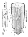
- a part of an introducer assembly 120 is illustrated in prior art Figure 1b in which the prior art filter 113 is percutaneously delivered through the jugular vein 154 of a patient. As shown, the filter 113 in its collapsed configuration is placed at the distal end 121 of an inner sheath 122 with anchoring hooks 116 of the filter 113 extending past the distal end 121.
- An outer sheath 126 is then disposed over the inner sheath 122 to avoid undesirably scratching or scraping of the anchoring hooks 116 against the introducer tube 130.
- the inner and outer sheaths 122, 126 along with a pusher member 132 are then moved together through the introducer tube 130 to deliver the filter 113 to the vena cava of the patient. It has been a challenge to design a vena cava filter with features that lessen the concerns of undesirably scratching or scraping of the anchoring hooks against outer walls of an introducer tube or a blood vessel while maintaining the effectiveness of the filter.
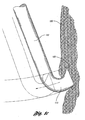
- FIG. 1c shows the result when the filter 113 is moved from an expanded state to a collapsed state for removal.
- barb 123 of the hook 113 penetrates deeper into the vessel wall 150.
- retraction of the strut 138 causes the barb 123 of the hook 113 to cut or tear tissue off the vessel wall 150.
- the present invention provides a removable vena cava filter for capturing thrombi in a blood vessel and the scope of the invention is set forth in the appended claims.
- the filter comprises a plurality of primary struts having first ends attached together along a longitudinal axis of the filter.
- Each strut has a body member extending from the first end along the longitudinal axis to an anchoring hook defining a strut axis.
- Each strut is configured to move along a strut path relative to the longitudinal axis between an expanded state for engaging with the blood vessel and a collapsed state for filter delivery or retrieval.
- Each anchoring hook has an angle of about 90 degrees relative to the strut axis.
- the body member is an arcuate segment.
- each primary strut is configured to cross another primary strut along the longitudinal axis such that the arcuate segments occupy a first diameter greater than a second diameter occupied by the anchoring hooks for filter retrieval or delivery.
- each arcuate segment extends arcuately along a longitudinal axis and linearly relative to a radial axis from the first end to the anchoring hook.
- the removable filter includes a plurality of secondary struts having connected ends attached together along the longitudinal axis.
- Each secondary strut has a first arch extending from the connected end and a second arch extending from the first arch to a free end.
- the second arch is configured to engage the blood vessel to centralize the filter in the expanded state in the blood vessel.
- the removable filter further includes a hub connected to axially house the first ends of the plurality of primary struts and the connected ends of the secondary struts.
- the filter further comprises a retrieval hook extending from the hub opposite the plurality of primary struts for removal of the filter from the blood vessel.
- pairs of secondary struts are positioned between pairs of primary struts.
- Each pair of secondary struts is twisted together near the connected ends of the secondary struts to form a twisted section.
- the twisted sections of the secondary struts effectively stiffen the struts to enhance their centering capabilities to prevent the filter from tilting when the filter is deployed in the blood vessel. Hence, engagement between the struts and the blood vessel is minimized which reduces the potential for the struts to become endothelialized within the blood vessel.
- a further feature of the twisted sections is that they prevent or at least minimize the secondary struts from entangling with the primary struts.
- Figure 1 a is a side view of a prior art filter deployed through the vasculature of a patient
- Figure 1b is a side view of an introducer assembly including the prior art filter to be delivered to the vena cava of a patient;
- Figure 1c is an enlarged view of an anchoring hook of the prior art filter in circle 1c of Figure 1 a the filter is being retracted from a vessel wall;
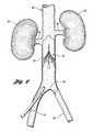
- Figure 2 is an illustration of the anatomy of the renal veins, the iliac veins, and the vena cava in which one embodiment of a vena cava filter of the present invention is deployed;
- Figure 3a is a side perspective view of a vena cava filter in an expanded state
- Figure 3b is an enlarged view of the vena cava filter depicting an anchoring hook in circle 3b;
- Figure 3c is a side view of the vena cava filter of Figure 3a in a collapsed state and disposed in an introducer tube;
- Figure 4 is an enlarged view of a portion of a second arcuate portion of a primary strut in circle 3b;
- Figure 5 is a cross-sectional view of a hub of the filter in Figure 3 taken along line 5-5;
- Figure 6a is a cross-sectional view of the vena cava depicting the filter partially deployed leading with the removal hook;
- Figure 6b is a cross-sectional view of the vena cava depicting the filter partially deployed leading with the anchoring hooks;
- Figure 7a is a cross-sectional view of the vena cava in which the filter of Figure 3 has been deployed;
- Figure 7b is an enlarged view of the filter of Figure 7a depicting an anchoring hook according to the invention engage in a vessel wall in circle 7b;
- Figure 7c is a view of part of a filter depicting another embodiment of an anchoring hook engaged in a vessel wall;
- Figure 7d is a view of part of filter depicting yet another embodiment of an anchoring hook engaged in a vessel wall
- Figure 8a is a cross-sectional view of the vena cava of Figure 7a taken along line 8-8;
- Figure 8b is a cross-sectional view of the vena cava of Figure 7a taken along line 8-8 depicting another embodiment of the filter;
- Figure 9a is a cross-sectional view of a blood vessel in which a retrieval sheath engages primary struts of the filter in Figure 3 for removal;
- Figure 9b is a cross-sectional view of a blood vessel in which the retrieval sheath includes the filter in the collapsed state for removal;
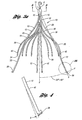
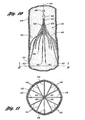
- Figure 10 is a cross-sectional view of a blood vessel showing a vena cava filter deployed within the blood vessel in accordance with another embodiment of the invention.
- Figure 11 is a view of the blood vessel and filter of Figure 10 taken along the line 11-11.
- Figure 2 illustrates a vena cava filter 10 implanted in the vena cava 50 for the purpose of lysing or capturing thrombi carried by the blood flowing through the iliac veins 54, 56 toward the heart and into the pulmonary arteries.
- the iliac veins merge at juncture 58 into the vena cava 50.
- the renal veins 60 from the kidneys 62 join the vena cava 50 downstream of juncture 58.
- the portion of the vena cava 50, between the juncture 58 and the renal veins 60 defines the inferior vena cava 52 in which the vena cava filter 10 has been percutaneously deployed through the femoral vein.
- the vena cava filter 10 has a length smaller than the length of the inferior vena cava 52. If the lower part of the filter extends into the iliac veins, filtering effectiveness will be compromised and if the filter wires cross over the origin of the renal veins the filter wires might interfere with the flow of blood from the kidneys.
- FIG. 3a illustrates filter 10 in an expanded state and comprising four primary struts 12 each having first ends that emanate from a hub 11.
- Hub 11 attaches by crimping first ends 14 of primary struts 12 together at a center point A in a compact bundle to define a central or longitudinal axis X of the filter as shown in Figure 3a .
- the hub 11 has a minimal diameter for the size of wire used to form the struts.
- the primary struts 12 are formed from superelastic material, stainless steel wire, cobalt-chromium-nickel-molybdenum-iron alloy, Nitinol, titanium, cobalt-chrome alloy, thermosetting and thermoplastic polymers, or any suitable material that will result in a self-opening or self-expanding filter.
- the primary struts 12 are preferably formed from wire having a round or near round cross-section with a diameter of at least about 0,381mm (0.015 inches).
- the primary struts 12 could take on any shape with rounded edges to maintain a non-turbulent blood flow therethrough.
- Each primary strut 12 includes a body member 15.
- the body member 15 is an arcuate segment 16 having a soft S-shape in an expanded state.
- each arcuate segment 16 is formed with a first curved portion 20 that is configured to softly bend away from the longitudinal or central axis X of the filter 10 and a second curved portion 23 that is configured to softly bend toward the longitudinal axis of the filter 10. Due to the soft bends of each arcuate segment 16, a prominence or a point of inflection on the primary strut 12 is substantially avoided to aid in non-traumatically engaging the vessel wall:
- each primary strut 12 terminates at an anchoring hook 26 having barb 29 defining a strut axis S of the respective primary strut 12.
- the anchoring hooks 26 will anchor in the vessel wall when the filter 10 is deployed at a delivery location in the blood vessel.
- Each primary strut 12 is configured to move along a strut path P between an expanded state for engaging the anchoring hooks 26 with the blood vessel and a collapsed state for filter retrieval or delivery.
- the strut path falls between about 20° and 40° from the longitudinal axis of the filter.
- each arcuate segment 16 extends arcuately along a longitudinal axis X (as shown in Figure 3a ) and linearly relative to a radial axis R (as shown in Figure 8a ) from the first end 14 to the anchoring hook 26.
- the primary struts 12 radially extend from the first ends 14, defining the radial axis R.
- the primary struts 12 extend linearly relative to the radial axis R and avoid entanglement with other struts.
- each arcuate segment 16 allows each primary strut 12 to cross another primary strut 12 along the longitudinal axis X in the collapsed state such that each anchoring hook 26 inwardly faces or is positioned along the longitudinal axis X away from the wall of a blood vessel for filter retrieval or delivery.
- each anchoring hook 26 extends from the arcuate segment 16 to barb 29 along strut path P to about a tangent point T on the strut path P.
- Hook 26 includes a bend 31 having an angle of up to about 90 degrees relative to the strut axis S. It has been found that, by forming bend 31 that forms the hook 26 so that the hook 26 extends to about a tangent point T on the strut path P, each hook 26 can be atraumatically retracted from the vessel wall without carrying substantial tissue therefrom. To accomplish this, it has also been found that the arc or bend 31 of the hook 26 is limited to 90 degrees from the strut axis S. It is to be noted that this principle could be applied to any filter design so long as the hook or barb point coincides with the strut path. As shown, each hook 26 includes an end face 33 having a cutback that is about parallel to the longitudinal axis of the filter 10.
- the anchoring hooks 26 are designed to allow for easy, non-traumatic removal of the filter from the vena cava when the condition of the patient requiring the filter passes. At the same time, the anchoring hooks 26 prevent the filter 10 from migrating from the delivery location in the blood vessel where it has been deposited. When the filter 10 is deployed in a blood vessel, the anchoring hooks 26 engage the walls of the blood vessel to define a first axial portion to secure the filter in the blood vessel.
- the primary struts 12 are shaped and dimensioned such that, when the filter 10 is freely expanded, the filter 10 has a diameter of between about 25 mm and 45 mm and a length of between about 3 cm and 7 cm.
- the filter 10 may have a diameter of about 35 mm and a length of about 5 cm when freely expanded.
- the primary struts 12 have sufficient spring strength that when the filter is deployed the anchoring hooks 26 will anchor into the vessel wall.
- the filter 10 includes a plurality of secondary struts 30 having connected ends 32 that also emanate from hub 11. Hub 11 attaches by crimping the connected ends 32 at the center point A of the secondary struts 30 together with the primary struts 12.
- each primary strut 12 has two secondary struts 30 in side-by-side relationship with the primary strut 12.
- the secondary struts 30 extend from the connected ends 32 to free ends 34 to centralize the filter 10 in the expanded state in the blood vessel.
- each secondary strut 30 extends arcuately along the longitudinal axis and linearly relative to the radial axis from the connected end 32 to the free end 34 for engaging the anchoring hooks 26 with the blood vessel.
- the secondary struts 30 extend linearly relative to the radial axis and avoid entanglement with other struts.
- the secondary struts 30 may be made from the same type of material as the primary struts 12. However, the secondary struts 30 may have a smaller diameter, e.g., at least about 0,305 mm (0.012 inches), than the primary struts 12.
- each of the secondary struts 30 is formed of a first arc 40 and a second arc 42.
- the first arc 40 extends from the connected end 32 away from the longitudinal axis X.
- the second arc 42 extends from the first arc 40 towards the longitudinal axis X.
- two secondary struts 30 are located on each side of one primary strut 12 to form a part of a netting configuration of the filter 10.
- hub 11 is preferably made of the same material as the primary and secondary struts to reduce the possibility of galvanic corrosion or molecular changes in the material due to welding.
- free ends 34 of the secondary struts 30 When freely expanded, free ends 34 of the secondary struts 30 will expand radially outwardly to a diameter of about 25 mm to 45 mm to engage the vessel wall.
- the secondary struts 30 may expand radially outwardly to a diameter of between about 35 mm and 45 mm.
- the second arcs 42 of the free ends 34 engage the wall of a blood vessel to define a second axial portion where the vessel wall is engaged.
- the secondary struts 30 function to stabilize the position of the filter 10 about the center of the blood vessel in which it is deployed.
- the filter 10 has two layers or portions of struts longitudinally engaging the vessel wall of the blood vessel.
- the length of the filter 10 is preferably defined by the length of a primary strut 12.
- the diameter of the hub 11 is defined by the size of a bundle containing the primary struts 12 and secondary struts 30.
- the eight secondary struts 30 minimally add to the diameter of the hub 11 or the overall length of the filter 10, due to the reduced diameter of each secondary strut 30. This is accomplished while maintaining the filter 10 in a centered attitude relative to the vessel wall and formed as a part of the netting configuration of the filter 10.
- removal hook 46 extends from hub 11 opposite primary and secondary struts 12 and 30.
- each arcuate segment 16 has a thickness of at least about 0,381 mm (0.015 inch) and a tensile strength of between about 1,97 and 2,28 GPa (285,000 pounds per square inch (psi) and 330,000 psi).
- Each anchoring hook 26 is integral with the arcuate segment 16 and has the thickness and the tensile strength of the arcuate segment.
- Each secondary strut 30 has a thickness of at least about (0.012 inch) and a tensile strength of between about 1,97 and 2,28 GPa (285,000 psi and 330,000 psi).
- Figure 3c illustrates the filter 10 in a collapsed state disposed in a delivery/retrieval tube 94 for delivery or retrieval.
- the filter 10 is shaped for each primary strut 12 to cross another primary strut 12 along the longitudinal axis X.
- the anchoring hooks 26 are configured to be inverted or inwardly faced or positioned along the longitudinal axis X and away from the walls of a blood vessel for retrieval and delivery of the filter 10. This inverted or inwardly facing configuration of the anchoring hooks 26 allows for simplified delivery and retrieval of filter 10.
- a concern that the anchoring hooks 26 in the collapsed state may scrape, scratch, or tear the inner wall of a delivery/retrieval tube is eliminated, since the filter 10 of the present invention is shaped to have the anchoring hooks 26 inwardly face or positioned along the longitudinal axis away from the blood vessel.
- a set of inner and outer delivery/retrieval sheaths may be eliminated during the delivery or retrieval of the filter 10 through the jugular vein. Rather, merely one delivery/retrieval tube with a loop snare mechanism may be used to deliver or retrieve the filter 10.
- each primary strut 12 is configured to cross another primary strut 12 along the longitudinal axis X such that the arcuate segments 16, first curved portions 20 or second curved portions 23, occupy a first diameter D1.
- the first diameter is greater than a' second diameter D2 occupied by the anchoring hooks 26 for filter retrieval or delivery. It has been found that the first diameter of the arcuate segments 16 serves to clear a path of retrieval, reducing radial force from the sheath or blood vessel on the anchoring hooks 26 during removal of the filter 10 from a patient. Reducing the radial force on the anchoring hooks 26 assists in preventing the anchoring hooks 26 from scraping, scratching, or tearing the inner wall of a sheath during removal of the filter 10 from a patient.
- the filter 10 may be delivered or retrieved by any suitable introducer (delivery or retrieval) tube.
- the introducer tube has an inside diameter of between about 4.5 French and 16 French, and more preferably between about 6.5 French and 14 French.
- Figure 4 illustrates primary strut 12 including distal bend 43 formed thereon and extending outwardly radially from the longitudinal axis X. As shown in Figure 4 , the distal bend 43 may extend outwardly at an angle G between about 0.5 degree to 2 degrees, preferably 1.0 degree. The distal bend 43 allows the filter 10 to filter thrombi effectively at a smaller inside diameter of a blood vessel than otherwise would be possible while maintaining the ability to collapse for delivery or retrieval.
- Figure 5 illustrates a cross-sectional view of the filter 10 of Figure 3a at hub 11.
- the hub 11 houses a bundle of first ends 14 of the four primary struts 14 and connected ends 32 of secondary struts 30.
- Figure 5 further depicts the configurations of the primary and secondary struts 12 and 30.
- the primary struts 12 are spaced between two secondary struts 30.
- the primary struts 12 may be spaced between any other suitably desired number of secondary struts 30 without falling beyond the scope of the present invention.
- Figures 6a and 6b both illustrate the filter 10 partially deployed in inferior vena cava 52.
- Figure 6a shows the filter 10 being delivered by a delivery tube 48 through the femoral vein of a patient
- Figure 6b shows the filter 10 being delivered by a delivery tube 50 through the jugular vein of a patient.
- a delivery tube is percutaneously inserted through the patient's vessel such that the distal end of the delivery tube is at the location of deployment.
- a wire guide is preferably used to guide the delivery tube to the location of deployment.
- the filter 10 is inserted through the proximal end of the delivery tube 48 with the removal hook 46 leading and anchoring hooks 26 of the primary struts 12 held by a filter retainer member for delivery via the femoral vein of a patient.
- the filter 10 is inserted through the proximal end of the delivery tube 50 with the anchoring hooks 26 of the primary struts 12 leading and the removal hook 46 trailing for delivery via the jugular vein of a patient.
- a pusher wire having a pusher member at its distal end may be fed through the proximal end of the delivery tube 50 thereby pushing the filter 10 until the filter 10 reaches the distal end of the delivery tube 50 to a desired location.
- the secondary struts 30 expand first to centralize or balance the filter within the vessel.
- the secondary struts 30 expand to an expanded position as shown in both Figures 6a and 6b .
- the second arcs 42 engage the inner wall of the vessel.
- the second arcs 42 of the secondary struts 30 function to stabilize the attitude of filter 10 about the center of the blood vessel.
- the anchoring hooks 26 of the primary struts 12 and the second arcs 42 of the secondary struts 30 are in engagement with the vessel wall.
- the anchoring hooks 26 of the primary struts 12 have anchored the filter 10 at the location of deployment in the vessel, preventing the filter 10 from moving with the blood flow through the vessel.
- the filter 10 is supported by two sets of struts that are spaced axially along the length of the filter.
- Figure 7a illustrates the filter 10 fully expanded after being deployed in inferior vena cava 52.
- the inferior vena cava 52 has been broken away so that the filter 10 can be seen.
- the direction of the blood flow BF is indicated in Figure 7a by the arrow that is labeled BF.
- the anchoring hooks 26 at the ends of the primary struts 12 are shown as being anchored in the inner lining of the inferior vena cava 52.
- the anchoring hooks 26 include barbs 29 that, in this embodiment, project toward the hub 11 of the filter as described above and shown in Figures 3a-3c .
- the barbs 29 function to retain the filter 10 in the location of deployment.
- the spring biased configuration of the primary struts 12 further causes the anchoring hooks 26 to engage the vessel wall and anchor the filter at the location of deployment. After initial deployment, the pressure of the blood flow on the filter 10 contributes in maintaining the barbs 29 anchored in the inner lining of the inferior vena cava 52. As seen in Figure 7a , the second arcs 42 of secondary struts 30 also have a spring biased configuration to engage with the vessel wall.
- the hub 11 and removal hook 46 are positioned downstream from the location at which the anchoring hooks 26 are anchored in the vessel. When captured by the struts 12 and 30, thrombi remains lodged in the filter. The filter 10 along with the thrombi may then be percutaneously removed from the vena cava. When the filter 10 is to be removed, the removal hook 46 is preferably grasped by a retrieval instrument that is percutaneously introduced in the vena cava in the direction of removal hook 16 first.
- Figure 7b depicts barb 29 of hook 26 engaged in the vessel wall 52 and (in phantom view) immediately after retraction therefrom.
- barb 29 allows for an atraumatic removal of the strut, avoiding tearing of tissue from the vessel wall 52. Additionally, as shown, barb 29 is pointed toward the direction of blood flow BF so that as the filter 10 is challenged by thrombi and forces tending to make the filter 10 migrate toward the heart, the hook 26 will tend to engage more vessel wall tissue and increase its migration resistance.
- the primary and secondary struts can be formed from any suitable material that will result in a self-opening or self-expanding filter, such as shape memory alloys.
- Shape memory alloys have the desirable property of becoming rigid, that is, returning to a remembered state, when heated above a transition temperature.
- a shape memory alloy suitable for the present invention is Ni'-Ti available under the more commonly known name Nitinol. When this material is heated above the transition temperature, the material undergoes a phase transformation from martensite to austenic, such that material returns to its remembered state.
- the transition temperature is dependent on the relative proportions of the alloying elements Ni and Ti and the optional inclusion of alloying additives.
- both the primary struts and the secondary struts are made from Nitinol with a transition temperature that is slightly below normal body temperature of humans, which is about 37°C (98.6°F).
- the alloy of the struts will transform to austenite, that is, the remembered state, which for the present invention is an expanded configuration when the filter is deployed in the blood vessel.
- the filter is cooled to transform the material to martensite which is more ductile than austenite, making the struts more malleable. As such, the filter can be more easily collapsed and pulled into the sheath for removal.
- both the primary struts and the secondary struts are made from Nitinol with a transition temperature that is above normal body temperature of humans, which is abut 37°C (98.6° F).
- the struts are in the martensitic state so that the struts are sufficiently ductile to bend or form into a desired shape, which for the present invention is an expanded configuration.
- the filter is heated to transform the alloy to austenite so that the filter becomes rigid and returns to a remembered state, which for the filter 20 is a collapsed configuration.
- Figure 7c depicts barb 129 of hook 127 engaged in the vessel wall 52 and (in phantom view) immediately after retraction therefrom.
- hook 126 extends to an end face 133 having a concave cutback.
- the end face 133 is formed by grinding to form a concave end.
- the hook 126 extends along strut path P to about a tangent point T on the strut path P.
- Hook 126 includes a bend 131 having an angle of up to about 90° relative to the strut axis S.
- barb 129 is formed to further help prevent filter migration away from the heart.
- the hollow or concave end will also increase the sharpness of the barb 129 lessening the likelihood of trauma to the vessel wall.
- Figure 7d depicts barb 229 of hook 226 engaged in the vessel wall 252 and (in phantom view) immediately after retraction therefrom.
- hook 226 extends further than the embodiment illustrated in Figure 7b .
- the hook 226 extends along strut path P to about a tangent point T on the strut path P.
- Hook 226 includes a bend 231 having an angle of up to about 90° relative to the strut axis S.
- straight extension portion 235 is substantially parallel to the tangent T of path P so that the strut may be atraumatically withdrawn from the vessel wall.
- each hook 226 includes an end face 233 having a cutback that is about parallel to the longitudinal axis of the filter.
- Figure 8a depicts a netting configuration or pattern formed by the primary struts 12, secondary struts 30, and the hub 11 relative to radial axis R.
- the netting pattern shown in Figure 8a functions to catch thrombi carried in the blood stream prior to reaching the heart and lungs to prevent the possibility of a pulmonary embolism.
- the netting pattern is sized to catch and stop thrombi that are of a size that are undesirable to be carried in the vasculature of the patient. Due to its compacted size, the hub minimally resists blood flow.
- Figure 8a depicts the netting pattern including primary struts and secondary struts at substantially equal angular space relative to each other.
- the netting pattern provides an even distribution between the primary and secondary struts to the blood flow, increasing the likelihood of capturing thrombi.
- each of the sets of primary struts 312 and secondary struts 330 may be independently spaced substantially equally at their respective portions relative to radial axis R'.
- the secondary struts 330 may be spaced equally relative to the other secondary struts 330 and the primary struts 312 may be spaced equally relative to the other primary struts 312.
- the netting pattern in this embodiment shown by the cross-sectional view of the vena cava (taken along line 8-8) will have uneven or unequal spacing between the primary struts 312 and secondary struts 330.
- Figures 9a and 9b illustrate part of a retrieval device 65 being used in a procedure for removing the filter 10 from the inferior vena cava 52.
- the retrieval device 65 is percutaneously introduced into the superior vena cava via the jugular vein.
- a removal catheter or sheath 68 of the retrieval device 65 is inserted into the superior vena cava.
- a wire 70 having a loop snare 72 at its distal end is threaded through the removal sheath 68 and is exited through the distal end of the sheath 68.
- the wire 70 is then manipulated by any suitable means from the proximal end of the retrieval device such that the loop snare 72 captures the removal hook 46 of the filter 10.
- the sheath 68 is passed over the filter 10.
- the primary struts 12 and then the secondary struts 30 engage the edge of the sheath 68 and are caused to pivot or undergo bend deflection at the hub 11 toward the longitudinal axis of the filter.
- the pivoting toward the longitudinal axis causes the ends of the struts 12 and 30 to be retracted from the vessel wall. In this way, only surface lesions 74 and small point lesions 76 on the vessel wall are created in the removal procedure.
- the surface lesions 74 are created by the ends of the secondary struts 30 and the small point lesions 76 are created by the anchoring hooks 26 of the primary struts 12.
- any other suitable procedure may be implemented to remove the filter from the patient.
- this device has been disclosed as being constructed from wire having a round cross section, it could also be cut from a tube of suitable material by laser cutting, electrical discharge machining or any other suitable process.
- a filter 420 includes four primary struts 438 and eight secondary struts 440 that extend from a hub 442.
- Each primary strut 438 terminates in an anchoring hook 452 with a barb 454.
- the primary struts 438 have sufficient spring strength such that when the filter is deployed in a vena cava 436, the anchoring hooks 452, in particular, the barbs 444, anchor into the vessel wall of the vena cava 436 to prevent the filter 420 from migrating from the delivery location.
- the pressure of the blood flow on the filter 420 contributes in maintaining the barbs 454 anchored in the inner lining of the vena cava 436.
- a pair of secondary struts 440 are positioned between adjacent primary struts 438.
- Each secondary strut 440 extends from the hub 442 and terminates in a tip 462 pointing toward the central axis 444.
- the tips 462 are located longitudinally between the hub 442 and the anchoring hooks 454 of the primary struts 438.
- the connected ends of each pair of secondary struts 440 positioned between adjacent primary struts are twisted together, defining a twisted section 464.
- the twisted sections 464 effectively stiffens each pair of secondary struts 440, thinner secondary struts may be used to provide the appropriate balancing forces to center the filter in the blood vessel. Moreover, an additional benefit of the twisted section is that they prevent the secondary struts from entangling with the primary struts.
- the secondary struts 440 can be made from the same type of material as the primary struts 438 and can be formed by the same process used to form the primary struts. However, the secondary struts may have a smaller diameter than the primary struts.
- each pair of secondary struts 440 positioned between adjacent primary struts 438 can be twisted about each other after the struts have been attached to the hub 442.
- Each twisted section 464 includes one or more twists.
- each twisted section 464 may include up to about ten twists. In certain implementations, the number of twists in each section 464 may be between about three to five twists. Increasing the number of twists increases the stiffness of the pair of secondary struts twisted about each other.
- the hub 442 is preferably made of the same material as the primary struts and secondary struts to minimize the possibility of galvanic corrosion.
- Figure 11 illustrates a netting pattern ("net") formed by the primary struts 438, the secondary struts 440, and the hub 442.
- This net functions to catch thrombi carried in the blood stream to prevent the thrombi from reaching the heart and lungs, where the thrombi could cause pulmonary embolism.
- the net is sized to catch and stop thrombi that are of a size that are undesirable in the vasculature of the patient.
- the struts 438 have substantially equal angular spacing between the struts.
- the hub 442 and a removal hook 466 attached to the hub are located downstream of the location at which the anchoring hooks 452 are anchored in the vessel 436.
- thrombi When captured by the struts, thrombi remain lodged in the filter 420.
- the filter 420 along with the thrombi may then be removed percutaneously from the vena cava.
- the removal hook 466 is typically grasped by the retrieval hook that is introduced in the vena cava percutaneously.
Abstract
Description
- The present invention relates to medical devices. More particularly, the invention relates to a removable vena cava clot filter that can be percutaneously placed in and removed from the vena cava of a patient.
- Filtering devices that are percutaneously placed in the vena cava have been available for over thirty years. A need for filtering devices arises in trauma patients, orthopedic surgery patients, neurosurgery patients, or in patients having medical conditions requiring bed rest or non-movement. During such medical conditions, the need for filtering devices arises due to the likelihood of thrombosis in the peripheral vasculature of patients wherein thrombi break away from the vessel wall, risking downstream embolism or embolization. For example, depending on the size, such thrombi pose a serious risk of pulmonary embolism wherein blood clots migrate from the peripheral vasculature through the heart and into the lungs.
- A filtering device can be deployed in the vena cava of a patient when, for example, anticoagulant therapy is contraindicated or has failed. Typically, filtering devices are permanent implants, each of which remains implanted in the patient for life, even though the condition or medical problem that required the device has passed. In more recent years, filters have been used or considered in preoperative patients and in patients predisposed to thrombosis which places the patient at risk for pulmonary embolism.
- The benefits of a vena cava filter have been well established, but improvements may be made. For example, filters generally have not been considered removable from a patient due to the likelihood of endotheliosis of the filter during treatment. After deployment of a filter in a patient, proliferating intimal cells begin to accumulate around the filter struts which contact the wall of the vessel. After a length of time, such ingrowth prevents removal of the filter without risk of trauma, requiring the filter to remain in the patient. As a result, there has been a need for an effective filter that can be removed after the underlying medical condition has passed.
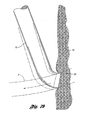
- Conventional filters commonly become off-centered or tilted with respect to the hub of the filter and the longitudinal axis of the vessel in which it has been inserted. As a result, the filter including the hub and the retrieval hook engage the vessel wall along their lengths and potentially become endothelialized therein. This condition is illustrated in prior art
Figure 1a in which aprior art filter 113 has been delivered by adelivery sheath 125 through thevessel 150 of a patient. In the event of this occurrence, there is a greater likelihood of endotheliosis of the filter to the blood vessel along a substantial length of the filter wire. As a result, the filter becomes a permanent implant in a shorter time period than otherwise. - A typical filter is disclosed in
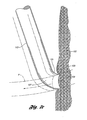
US-A-5242462 . - In addition, further improvements may be made related to the delivery or retrieval of vena cava filters. For delivery of vena cava filters, an introducer system having an introducer tube may be percutaneously inserted in the vena cava of a patient through the femoral vein or the jugular vein. A part of an
introducer assembly 120 is illustrated in prior artFigure 1b in which theprior art filter 113 is percutaneously delivered through thejugular vein 154 of a patient. As shown, thefilter 113 in its collapsed configuration is placed at thedistal end 121 of aninner sheath 122 with anchoringhooks 116 of thefilter 113 extending past thedistal end 121. Anouter sheath 126 is then disposed over theinner sheath 122 to avoid undesirably scratching or scraping of the anchoringhooks 116 against theintroducer tube 130. The inner andouter sheaths pusher member 132 are then moved together through theintroducer tube 130 to deliver thefilter 113 to the vena cava of the patient. It has been a challenge to design a vena cava filter with features that lessen the concerns of undesirably scratching or scraping of the anchoring hooks against outer walls of an introducer tube or a blood vessel while maintaining the effectiveness of the filter. - Furthermore, it is also a challenge to provide a removable vena cava filter having an anchoring feature that prevents migration toward the heart while allowing easy, non-traumatic removal when the patient's medical condition no longer exists. A vena cava filter can be subjected to considerable forces when the filter is substantially full of clot and the patient strains or performs a valsalva. This tends to dilate the vena cava and force a large volume of blood toward the heart. There have been incidences where filters designed for permanent implantation have been dislodged and migrated into the heart when confronted with such a challenge. For example,
Figure 1c shows the result when thefilter 113 is moved from an expanded state to a collapsed state for removal. As the blood flow tends to push thefilter 113 toward the heart,barb 123 of thehook 113 penetrates deeper into thevessel wall 150. As a result, retraction of the strut 138 causes thebarb 123 of thehook 113 to cut or tear tissue off thevessel wall 150. - The present invention provides a removable vena cava filter for capturing thrombi in a blood vessel and the scope of the invention is set forth in the appended claims. The filter comprises a plurality of primary struts having first ends attached together along a longitudinal axis of the filter. Each strut has a body member extending from the first end along the longitudinal axis to an anchoring hook defining a strut axis. Each strut is configured to move along a strut path relative to the longitudinal axis between an expanded state for engaging with the blood vessel and a collapsed state for filter delivery or retrieval. Each anchoring hook has an angle of about 90 degrees relative to the strut axis.
- In another embodiment the body member is an arcuate segment. In the collapsed state, each primary strut is configured to cross another primary strut along the longitudinal axis such that the arcuate segments occupy a first diameter greater than a second diameter occupied by the anchoring hooks for filter retrieval or delivery. In the expanded state, each arcuate segment extends arcuately along a longitudinal axis and linearly relative to a radial axis from the first end to the anchoring hook.
- In another embodiment, the removable filter includes a plurality of secondary struts having connected ends attached together along the longitudinal axis. Each secondary strut has a first arch extending from the connected end and a second arch extending from the first arch to a free end. The second arch is configured to engage the blood vessel to centralize the filter in the expanded state in the blood vessel.
- In yet another embodiment, the removable filter further includes a hub connected to axially house the first ends of the plurality of primary struts and the connected ends of the secondary struts. The filter further comprises a retrieval hook extending from the hub opposite the plurality of primary struts for removal of the filter from the blood vessel.
- In certain embodiments, pairs of secondary struts are positioned between pairs of primary struts. Each pair of secondary struts is twisted together near the connected ends of the secondary struts to form a twisted section. The twisted sections of the secondary struts effectively stiffen the struts to enhance their centering capabilities to prevent the filter from tilting when the filter is deployed in the blood vessel. Hence, engagement between the struts and the blood vessel is minimized which reduces the potential for the struts to become endothelialized within the blood vessel. A further feature of the twisted sections is that they prevent or at least minimize the secondary struts from entangling with the primary struts.
- Further aspects, features, and advantages of the invention will become apparent from consideration of the following description and the appended claims when taken in connection with the accompanying drawings.
-
Figure 1 a is a side view of a prior art filter deployed through the vasculature of a patient; -
Figure 1b is a side view of an introducer assembly including the prior art filter to be delivered to the vena cava of a patient; -
Figure 1c is an enlarged view of an anchoring hook of the prior art filter in circle 1c ofFigure 1 a the filter is being retracted from a vessel wall; -
Figure 2 is an illustration of the anatomy of the renal veins, the iliac veins, and the vena cava in which one embodiment of a vena cava filter of the present invention is deployed; -
Figure 3a is a side perspective view of a vena cava filter in an expanded state; -
Figure 3b is an enlarged view of the vena cava filter depicting an anchoring hook in circle 3b; -
Figure 3c is a side view of the vena cava filter ofFigure 3a in a collapsed state and disposed in an introducer tube; -
Figure 4 is an enlarged view of a portion of a second arcuate portion of a primary strut in circle 3b; -
Figure 5 is a cross-sectional view of a hub of the filter inFigure 3 taken along line 5-5; -
Figure 6a is a cross-sectional view of the vena cava depicting the filter partially deployed leading with the removal hook; -
Figure 6b is a cross-sectional view of the vena cava depicting the filter partially deployed leading with the anchoring hooks; -
Figure 7a is a cross-sectional view of the vena cava in which the filter ofFigure 3 has been deployed; -
Figure 7b is an enlarged view of the filter ofFigure 7a depicting an anchoring hook according to the invention engage in a vessel wall in circle 7b; -
Figure 7c is a view of part of a filter depicting another embodiment of an anchoring hook engaged in a vessel wall; -
Figure 7d is a view of part of filter depicting yet another embodiment of an anchoring hook engaged in a vessel wall; -
Figure 8a is a cross-sectional view of the vena cava ofFigure 7a taken along line 8-8; -
Figure 8b is a cross-sectional view of the vena cava ofFigure 7a taken along line 8-8 depicting another embodiment of the filter; -
Figure 9a is a cross-sectional view of a blood vessel in which a retrieval sheath engages primary struts of the filter inFigure 3 for removal; -
Figure 9b is a cross-sectional view of a blood vessel in which the retrieval sheath includes the filter in the collapsed state for removal; -
Figure 10 is a cross-sectional view of a blood vessel showing a vena cava filter deployed within the blood vessel in accordance with another embodiment of the invention; and -
Figure 11 is a view of the blood vessel and filter ofFigure 10 taken along the line 11-11. - In accordance with one embodiment,
Figure 2 illustrates avena cava filter 10 implanted in thevena cava 50 for the purpose of lysing or capturing thrombi carried by the blood flowing through theiliac veins juncture 58 into thevena cava 50. Therenal veins 60 from thekidneys 62 join thevena cava 50 downstream ofjuncture 58. The portion of thevena cava 50, between thejuncture 58 and therenal veins 60, defines theinferior vena cava 52 in which thevena cava filter 10 has been percutaneously deployed through the femoral vein. Preferably, thevena cava filter 10 has a length smaller than the length of theinferior vena cava 52. If the lower part of the filter extends into the iliac veins, filtering effectiveness will be compromised and if the filter wires cross over the origin of the renal veins the filter wires might interfere with the flow of blood from the kidneys. - This embodiment will be further discussed with reference to
Figures 3-9 in which filter 10 is shown.Figure 3a illustratesfilter 10 in an expanded state and comprising fourprimary struts 12 each having first ends that emanate from ahub 11.Hub 11 attaches by crimping first ends 14 ofprimary struts 12 together at a center point A in a compact bundle to define a central or longitudinal axis X of the filter as shown inFigure 3a . Thehub 11 has a minimal diameter for the size of wire used to form the struts. - Preferably, the primary struts 12 are formed from superelastic material, stainless steel wire, cobalt-chromium-nickel-molybdenum-iron alloy, Nitinol, titanium, cobalt-chrome alloy, thermosetting and thermoplastic polymers, or any suitable material that will result in a self-opening or self-expanding filter. In this embodiment, the primary struts 12 are preferably formed from wire having a round or near round cross-section with a diameter of at least about 0,381mm (0.015 inches). Of course, it is not necessary that the primary struts have a round cross-section. For example, the primary struts 12 could take on any shape with rounded edges to maintain a non-turbulent blood flow therethrough.
- Each
primary strut 12 includes abody member 15. In this embodiment, thebody member 15 is anarcuate segment 16 having a soft S-shape in an expanded state. In the expanded state, eacharcuate segment 16 is formed with a firstcurved portion 20 that is configured to softly bend away from the longitudinal or central axis X of thefilter 10 and a secondcurved portion 23 that is configured to softly bend toward the longitudinal axis of thefilter 10. Due to the soft bends of eacharcuate segment 16, a prominence or a point of inflection on theprimary strut 12 is substantially avoided to aid in non-traumatically engaging the vessel wall: - As shown in
Figures 3a and3b , eachprimary strut 12 terminates at ananchoring hook 26 havingbarb 29 defining a strut axis S of the respectiveprimary strut 12. The anchoring hooks 26 will anchor in the vessel wall when thefilter 10 is deployed at a delivery location in the blood vessel. Eachprimary strut 12 is configured to move along a strut path P between an expanded state for engaging the anchoring hooks 26 with the blood vessel and a collapsed state for filter retrieval or delivery. In this embodiment, the strut path falls between about 20° and 40° from the longitudinal axis of the filter. - In the expanded state, each
arcuate segment 16 extends arcuately along a longitudinal axis X (as shown inFigure 3a ) and linearly relative to a radial axis R (as shown inFigure 8a ) from thefirst end 14 to the anchoringhook 26. As shown inFigure 8a , the primary struts 12 radially extend from the first ends 14, defining the radial axis R. In this embodiment, the primary struts 12 extend linearly relative to the radial axis R and avoid entanglement with other struts. - As discussed in greater detail below, the soft bends of each
arcuate segment 16 allow eachprimary strut 12 to cross anotherprimary strut 12 along the longitudinal axis X in the collapsed state such that each anchoringhook 26 inwardly faces or is positioned along the longitudinal axis X away from the wall of a blood vessel for filter retrieval or delivery. - According to the invention each anchoring
hook 26 extends from thearcuate segment 16 tobarb 29 along strut path P to about a tangent point T on the strutpath P. Hook 26 includes a bend 31 having an angle of up to about 90 degrees relative to the strut axis S. It has been found that, by forming bend 31 that forms thehook 26 so that thehook 26 extends to about a tangent point T on the strut path P, eachhook 26 can be atraumatically retracted from the vessel wall without carrying substantial tissue therefrom. To accomplish this, it has also been found that the arc or bend 31 of thehook 26 is limited to 90 degrees from the strut axis S. It is to be noted that this principle could be applied to any filter design so long as the hook or barb point coincides with the strut path. As shown, eachhook 26 includes an end face 33 having a cutback that is about parallel to the longitudinal axis of thefilter 10. - The anchoring hooks 26 are designed to allow for easy, non-traumatic removal of the filter from the vena cava when the condition of the patient requiring the filter passes. At the same time, the anchoring hooks 26 prevent the
filter 10 from migrating from the delivery location in the blood vessel where it has been deposited. When thefilter 10 is deployed in a blood vessel, the anchoring hooks 26 engage the walls of the blood vessel to define a first axial portion to secure the filter in the blood vessel. - The primary struts 12 are shaped and dimensioned such that, when the
filter 10 is freely expanded, thefilter 10 has a diameter of between about 25 mm and 45 mm and a length of between about 3 cm and 7 cm. For example, thefilter 10 may have a diameter of about 35 mm and a length of about 5 cm when freely expanded. The primary struts 12 have sufficient spring strength that when the filter is deployed the anchoring hooks 26 will anchor into the vessel wall. - In this embodiment, the
filter 10 includes a plurality ofsecondary struts 30 having connected ends 32 that also emanate fromhub 11.Hub 11 attaches by crimping the connected ends 32 at the center point A of thesecondary struts 30 together with the primary struts 12. In this embodiment, eachprimary strut 12 has twosecondary struts 30 in side-by-side relationship with theprimary strut 12. The secondary struts 30 extend from the connected ends 32 to free ends 34 to centralize thefilter 10 in the expanded state in the blood vessel. As shown, eachsecondary strut 30 extends arcuately along the longitudinal axis and linearly relative to the radial axis from theconnected end 32 to thefree end 34 for engaging the anchoring hooks 26 with the blood vessel. As with the primary struts 12, thesecondary struts 30 extend linearly relative to the radial axis and avoid entanglement with other struts. - The secondary struts 30 may be made from the same type of material as the primary struts 12. However, the
secondary struts 30 may have a smaller diameter, e.g., at least about 0,305 mm (0.012 inches), than the primary struts 12. In this embodiment, each of thesecondary struts 30 is formed of afirst arc 40 and asecond arc 42. Thefirst arc 40 extends from theconnected end 32 away from the longitudinal axis X. Thesecond arc 42 extends from thefirst arc 40 towards the longitudinal axis X. As shown, twosecondary struts 30 are located on each side of oneprimary strut 12 to form a part of a netting configuration of thefilter 10. In this embodiment,hub 11 is preferably made of the same material as the primary and secondary struts to reduce the possibility of galvanic corrosion or molecular changes in the material due to welding. - When freely expanded, free ends 34 of the
secondary struts 30 will expand radially outwardly to a diameter of about 25 mm to 45 mm to engage the vessel wall. For example, thesecondary struts 30 may expand radially outwardly to a diameter of between about 35 mm and 45 mm. The second arcs 42 of the free ends 34 engage the wall of a blood vessel to define a second axial portion where the vessel wall is engaged. The secondary struts 30 function to stabilize the position of thefilter 10 about the center of the blood vessel in which it is deployed. As a result, thefilter 10 has two layers or portions of struts longitudinally engaging the vessel wall of the blood vessel. The length of thefilter 10 is preferably defined by the length of aprimary strut 12. Furthermore, the diameter of thehub 11 is defined by the size of a bundle containing the primary struts 12 andsecondary struts 30. In this embodiment, the eightsecondary struts 30 minimally add to the diameter of thehub 11 or the overall length of thefilter 10, due to the reduced diameter of eachsecondary strut 30. This is accomplished while maintaining thefilter 10 in a centered attitude relative to the vessel wall and formed as a part of the netting configuration of thefilter 10. As shown,removal hook 46 extends fromhub 11 opposite primary andsecondary struts - In this embodiment, each
arcuate segment 16 has a thickness of at least about 0,381 mm (0.015 inch) and a tensile strength of between about 1,97 and 2,28 GPa (285,000 pounds per square inch (psi) and 330,000 psi). Each anchoringhook 26 is integral with thearcuate segment 16 and has the thickness and the tensile strength of the arcuate segment. Eachsecondary strut 30 has a thickness of at least about (0.012 inch) and a tensile strength of between about 1,97 and 2,28 GPa (285,000 psi and 330,000 psi). -
Figure 3c illustrates thefilter 10 in a collapsed state disposed in a delivery/retrieval tube 94 for delivery or retrieval. As shown, thefilter 10 is shaped for eachprimary strut 12 to cross anotherprimary strut 12 along the longitudinal axis X. As a result, in the collapsed state, the anchoring hooks 26 are configured to be inverted or inwardly faced or positioned along the longitudinal axis X and away from the walls of a blood vessel for retrieval and delivery of thefilter 10. This inverted or inwardly facing configuration of the anchoring hooks 26 allows for simplified delivery and retrieval offilter 10. For example, a concern that the anchoring hooks 26 in the collapsed state may scrape, scratch, or tear the inner wall of a delivery/retrieval tube is eliminated, since thefilter 10 of the present invention is shaped to have the anchoring hooks 26 inwardly face or positioned along the longitudinal axis away from the blood vessel. In fact, a set of inner and outer delivery/retrieval sheaths (see prior artFigure 1b ) may be eliminated during the delivery or retrieval of thefilter 10 through the jugular vein. Rather, merely one delivery/retrieval tube with a loop snare mechanism may be used to deliver or retrieve thefilter 10. - Moreover, in the collapsed state, each
primary strut 12 is configured to cross anotherprimary strut 12 along the longitudinal axis X such that thearcuate segments 16, firstcurved portions 20 or secondcurved portions 23, occupy a first diameter D1. In this embodiment, the first diameter is greater than a' second diameter D2 occupied by the anchoring hooks 26 for filter retrieval or delivery. It has been found that the first diameter of thearcuate segments 16 serves to clear a path of retrieval, reducing radial force from the sheath or blood vessel on the anchoring hooks 26 during removal of thefilter 10 from a patient. Reducing the radial force on the anchoring hooks 26 assists in preventing the anchoring hooks 26 from scraping, scratching, or tearing the inner wall of a sheath during removal of thefilter 10 from a patient. - In this embodiment, it is to be noted that the
filter 10 may be delivered or retrieved by any suitable introducer (delivery or retrieval) tube. However, it is preferred that the introducer tube has an inside diameter of between about 4.5 French and 16 French, and more preferably between about 6.5 French and 14 French. -
Figure 4 illustratesprimary strut 12 includingdistal bend 43 formed thereon and extending outwardly radially from the longitudinal axis X. As shown inFigure 4 , thedistal bend 43 may extend outwardly at an angle G between about 0.5 degree to 2 degrees, preferably 1.0 degree. Thedistal bend 43 allows thefilter 10 to filter thrombi effectively at a smaller inside diameter of a blood vessel than otherwise would be possible while maintaining the ability to collapse for delivery or retrieval. -
Figure 5 illustrates a cross-sectional view of thefilter 10 ofFigure 3a athub 11. As shown, thehub 11 houses a bundle of first ends 14 of the fourprimary struts 14 and connected ends 32 ofsecondary struts 30.Figure 5 further depicts the configurations of the primary andsecondary struts secondary struts 30. Of course, the primary struts 12 may be spaced between any other suitably desired number ofsecondary struts 30 without falling beyond the scope of the present invention. - In this embodiment,
Figures 6a and 6b both illustrate thefilter 10 partially deployed ininferior vena cava 52.Figure 6a shows thefilter 10 being delivered by adelivery tube 48 through the femoral vein of a patient andFigure 6b shows thefilter 10 being delivered by adelivery tube 50 through the jugular vein of a patient. For deployment of thefilter 10, a delivery tube is percutaneously inserted through the patient's vessel such that the distal end of the delivery tube is at the location of deployment. In this embodiment, a wire guide is preferably used to guide the delivery tube to the location of deployment. InFigure 6a , thefilter 10 is inserted through the proximal end of thedelivery tube 48 with theremoval hook 46 leading and anchoring hooks 26 of the primary struts 12 held by a filter retainer member for delivery via the femoral vein of a patient. - In
Figure 6b , thefilter 10 is inserted through the proximal end of thedelivery tube 50 with the anchoring hooks 26 of the primary struts 12 leading and theremoval hook 46 trailing for delivery via the jugular vein of a patient. In this embodiment, a pusher wire having a pusher member at its distal end may be fed through the proximal end of thedelivery tube 50 thereby pushing thefilter 10 until thefilter 10 reaches the distal end of thedelivery tube 50 to a desired location. - During deployment, the
secondary struts 30 expand first to centralize or balance the filter within the vessel. When the free ends of the secondary struts emerge from the distal end of either of thedelivery tubes secondary struts 30 expand to an expanded position as shown in bothFigures 6a and 6b . The second arcs 42 engage the inner wall of the vessel. The second arcs 42 of thesecondary struts 30 function to stabilize the attitude offilter 10 about the center of the blood vessel. When delivering through the jugular vein (Figure 6b ), thefilter 10 is then pushed further by the pusher wire (not shown) until it is fully deployed. - When the
filter 10 is fully expanded in the vena cava, the anchoring hooks 26 of the primary struts 12 and the second arcs 42 of thesecondary struts 30 are in engagement with the vessel wall. The anchoring hooks 26 of the primary struts 12 have anchored thefilter 10 at the location of deployment in the vessel, preventing thefilter 10 from moving with the blood flow through the vessel. As a result, thefilter 10 is supported by two sets of struts that are spaced axially along the length of the filter. -
Figure 7a illustrates thefilter 10 fully expanded after being deployed ininferior vena cava 52. As shown, theinferior vena cava 52 has been broken away so that thefilter 10 can be seen. The direction of the blood flow BF is indicated inFigure 7a by the arrow that is labeled BF. The anchoring hooks 26 at the ends of the primary struts 12 are shown as being anchored in the inner lining of theinferior vena cava 52. The anchoring hooks 26 includebarbs 29 that, in this embodiment, project toward thehub 11 of the filter as described above and shown inFigures 3a-3c . Thebarbs 29 function to retain thefilter 10 in the location of deployment. - The spring biased configuration of the primary struts 12 further causes the anchoring hooks 26 to engage the vessel wall and anchor the filter at the location of deployment. After initial deployment, the pressure of the blood flow on the
filter 10 contributes in maintaining thebarbs 29 anchored in the inner lining of theinferior vena cava 52. As seen inFigure 7a , the second arcs 42 ofsecondary struts 30 also have a spring biased configuration to engage with the vessel wall. - As seen in
Figure 7a , thehub 11 andremoval hook 46 are positioned downstream from the location at which the anchoring hooks 26 are anchored in the vessel. When captured by thestruts filter 10 along with the thrombi may then be percutaneously removed from the vena cava. When thefilter 10 is to be removed, theremoval hook 46 is preferably grasped by a retrieval instrument that is percutaneously introduced in the vena cava in the direction ofremoval hook 16 first. -
Figure 7b depictsbarb 29 ofhook 26 engaged in thevessel wall 52 and (in phantom view) immediately after retraction therefrom. As discussed inFigures 3a-3c ,barb 29 allows for an atraumatic removal of the strut, avoiding tearing of tissue from thevessel wall 52. Additionally, as shown,barb 29 is pointed toward the direction of blood flow BF so that as thefilter 10 is challenged by thrombi and forces tending to make thefilter 10 migrate toward the heart, thehook 26 will tend to engage more vessel wall tissue and increase its migration resistance. - The primary and secondary struts can be formed from any suitable material that will result in a self-opening or self-expanding filter, such as shape memory alloys. Shape memory alloys have the desirable property of becoming rigid, that is, returning to a remembered state, when heated above a transition temperature. A shape memory alloy suitable for the present invention is Ni'-Ti available under the more commonly known name Nitinol. When this material is heated above the transition temperature, the material undergoes a phase transformation from martensite to austenic, such that material returns to its remembered state. The transition temperature is dependent on the relative proportions of the alloying elements Ni and Ti and the optional inclusion of alloying additives.
- In other embodiments, both the primary struts and the secondary struts are made from Nitinol with a transition temperature that is slightly below normal body temperature of humans, which is about 37°C (98.6°F). Thus, when the filter is deployed in the vena cave and exposed to normal body temperature, the alloy of the struts will transform to austenite, that is, the remembered state, which for the present invention is an expanded configuration when the filter is deployed in the blood vessel. To remove the filter, the filter is cooled to transform the material to martensite which is more ductile than austenite, making the struts more malleable. As such, the filter can be more easily collapsed and pulled into the sheath for removal.
- In certain embodiments, both the primary struts and the secondary struts are made from Nitinol with a transition temperature that is above normal body temperature of humans, which is abut 37°C (98.6° F). Thus, when the filter is deployed in the vena cave and exposed to normal body temperature, the struts are in the martensitic state so that the struts are sufficiently ductile to bend or form into a desired shape, which for the present invention is an expanded configuration. To remove the filter, the filter is heated to transform the alloy to austenite so that the filter becomes rigid and returns to a remembered state, which for the
filter 20 is a collapsed configuration. - In another embodiment,
Figure 7c depictsbarb 129 ofhook 127 engaged in thevessel wall 52 and (in phantom view) immediately after retraction therefrom. As shown,hook 126 extends to anend face 133 having a concave cutback. In this embodiment, theend face 133 is formed by grinding to form a concave end. Thehook 126 extends along strut path P to about a tangent point T on the strutpath P. Hook 126 includes abend 131 having an angle of up to about 90° relative to the strut axis S. Moreover,barb 129 is formed to further help prevent filter migration away from the heart. The hollow or concave end will also increase the sharpness of thebarb 129 lessening the likelihood of trauma to the vessel wall. - In yet another embodiment,
Figure 7d depictsbarb 229 ofhook 226 engaged in thevessel wall 252 and (in phantom view) immediately after retraction therefrom. As shown,hook 226 extends further than the embodiment illustrated inFigure 7b . By extending the length of thehook 226, the depth of engagement in the vessel wall can be increased. However, thehook 226 extends along strut path P to about a tangent point T on the strutpath P. Hook 226 includes abend 231 having an angle of up to about 90° relative to the strut axis S. As shown, straight extension portion 235 is substantially parallel to the tangent T of path P so that the strut may be atraumatically withdrawn from the vessel wall. As in the embodiment depicted inFigure 3b , eachhook 226 includes anend face 233 having a cutback that is about parallel to the longitudinal axis of the filter. -
Figure 8a depicts a netting configuration or pattern formed by the primary struts 12,secondary struts 30, and thehub 11 relative to radial axis R. The netting pattern shown inFigure 8a functions to catch thrombi carried in the blood stream prior to reaching the heart and lungs to prevent the possibility of a pulmonary embolism. The netting pattern is sized to catch and stop thrombi that are of a size that are undesirable to be carried in the vasculature of the patient. Due to its compacted size, the hub minimally resists blood flow. -
Figure 8a depicts the netting pattern including primary struts and secondary struts at substantially equal angular space relative to each other. The netting pattern provides an even distribution between the primary and secondary struts to the blood flow, increasing the likelihood of capturing thrombi. However, as shown inFigure 8b , it is to be understood that each of the sets ofprimary struts 312 andsecondary struts 330 may be independently spaced substantially equally at their respective portions relative to radial axis R'. For example, thesecondary struts 330 may be spaced equally relative to the othersecondary struts 330 and theprimary struts 312 may be spaced equally relative to the other primary struts 312. As a result, the netting pattern in this embodiment shown by the cross-sectional view of the vena cava (taken along line 8-8) will have uneven or unequal spacing between theprimary struts 312 andsecondary struts 330. -
Figures 9a and 9b illustrate part of aretrieval device 65 being used in a procedure for removing thefilter 10 from theinferior vena cava 52. Theretrieval device 65 is percutaneously introduced into the superior vena cava via the jugular vein. In this procedure, a removal catheter orsheath 68 of theretrieval device 65 is inserted into the superior vena cava. Awire 70 having aloop snare 72 at its distal end is threaded through theremoval sheath 68 and is exited through the distal end of thesheath 68. Thewire 70 is then manipulated by any suitable means from the proximal end of the retrieval device such that theloop snare 72 captures theremoval hook 46 of thefilter 10. Using counter traction by pulling thewire 70 while pushing thesheath 68, thesheath 68 is passed over thefilter 10. As thesheath 68 passes over thefilter 10, the primary struts 12 and then thesecondary struts 30 engage the edge of thesheath 68 and are caused to pivot or undergo bend deflection at thehub 11 toward the longitudinal axis of the filter. The pivoting toward the longitudinal axis causes the ends of thestruts lesions 74 andsmall point lesions 76 on the vessel wall are created in the removal procedure. As shown, thesurface lesions 74 are created by the ends of thesecondary struts 30 and thesmall point lesions 76 are created by the anchoring hooks 26 of the primary struts 12. However, it is to be noted that any other suitable procedure may be implemented to remove the filter from the patient. - Although the embodiments of this device have been disclosed as being constructed from wire having a round cross section, it could also be cut from a tube of suitable material by laser cutting, electrical discharge machining or any other suitable process.
- In another embodiment shown in
Figures 10 and 11 , afilter 420 includes fourprimary struts 438 and eightsecondary struts 440 that extend from ahub 442. Eachprimary strut 438 terminates in ananchoring hook 452 with abarb 454. The primary struts 438 have sufficient spring strength such that when the filter is deployed in avena cava 436, the anchoring hooks 452, in particular, thebarbs 444, anchor into the vessel wall of thevena cava 436 to prevent thefilter 420 from migrating from the delivery location. The pressure of the blood flow on thefilter 420 contributes in maintaining thebarbs 454 anchored in the inner lining of thevena cava 436. - A pair of
secondary struts 440 are positioned between adjacentprimary struts 438. Eachsecondary strut 440 extends from thehub 442 and terminates in atip 462 pointing toward thecentral axis 444. Thetips 462 are located longitudinally between thehub 442 and the anchoring hooks 454 of theprimary struts 438. The connected ends of each pair ofsecondary struts 440 positioned between adjacent primary struts are twisted together, defining atwisted section 464. - Since the
twisted sections 464 effectively stiffens each pair ofsecondary struts 440, thinner secondary struts may be used to provide the appropriate balancing forces to center the filter in the blood vessel. Moreover, an additional benefit of the twisted section is that they prevent the secondary struts from entangling with the primary struts. - The
secondary struts 440 can be made from the same type of material as theprimary struts 438 and can be formed by the same process used to form the primary struts. However, the secondary struts may have a smaller diameter than the primary struts. To form thetwisted sections 464, each pair ofsecondary struts 440 positioned between adjacentprimary struts 438 can be twisted about each other after the struts have been attached to thehub 442. Eachtwisted section 464 includes one or more twists. For example, eachtwisted section 464 may include up to about ten twists. In certain implementations, the number of twists in eachsection 464 may be between about three to five twists. Increasing the number of twists increases the stiffness of the pair of secondary struts twisted about each other. Thehub 442 is preferably made of the same material as the primary struts and secondary struts to minimize the possibility of galvanic corrosion. -
Figure 11 illustrates a netting pattern ("net") formed by theprimary struts 438, thesecondary struts 440, and thehub 442. This net functions to catch thrombi carried in the blood stream to prevent the thrombi from reaching the heart and lungs, where the thrombi could cause pulmonary embolism. The net is sized to catch and stop thrombi that are of a size that are undesirable in the vasculature of the patient. As illustrated, thestruts 438 have substantially equal angular spacing between the struts. - The
hub 442 and aremoval hook 466 attached to the hub are located downstream of the location at which the anchoring hooks 452 are anchored in thevessel 436. When captured by the struts, thrombi remain lodged in thefilter 420. Thefilter 420 along with the thrombi may then be removed percutaneously from the vena cava. When thefilter 420 is to be removed, theremoval hook 466 is typically grasped by the retrieval hook that is introduced in the vena cava percutaneously. - While the present invention has been described in terms of preferred embodiments, it will be understood, of course, that the invention is not limited thereto since modifications may be made to those skilled in the art, particularly in light of the foregoing teachings.
Claims (14)
- A removable filter (10) for capturing thrombi in a blood vessel, the filter comprising: a plurality of struts (20) having first ends attached together along a longitudinal axis (X) of the filter, each strut having a body member (15) extending from the first end along the longitudinal axis to an anchoring hook (26) defining a strut axis (S), each strut being configured to move along a strut path relative to the longitudinal axis between an expanded state for engaging with the blood vessel and a collapsed state for filter delivery or retrieval, each anchoring hook having an angle of up to about 90 degrees relative to the strut axis; wherein each anchoring hook (26) is integral with the body member (15) and has the same thickness and tensile strength of the body member (15); wherein the plurality of struts is a plurality of primary struts (20) and is characterised in that each anchoring hook extends from the body member along its strut path at about a tangent point of the strut path, such that each hook can be atraumatically retracted from the vessel wall without carrying substantial tissue therefrom.
- The removable filter of claim 1 further comprising: a plurality of secondary struts (30) having connected ends attached together along the longitudinal axis (X), each secondary strut having a first arc (40) extending from the connected end and a second arc (42) extending from the first arc to a free end, the second arc being configured to engage the blood vessel to centralize the filter in the expanded state in the blood vessel; a hub (11) configured to axially house the first ends of the plurality of primary struts; and a retrieval hook extending from the hub opposite the plurality of primary struts for removal of the filter from the blood vessel.
- The removable filter of claim 2 wherein the body member is an arcuate segment including a first curved portion and a second curved portion, the first curved portion extending from the first end, the second curved portion extending from the first curved portion and terminating at the anchoring hook.
- The removable filter of claim 3 wherein the first curved portion is configured to extend radially from the longitudinal axis of the filter and the second curved portion is configured to extend radially toward the longitudinal axis of the filter.
- The removable filter of claim 3 wherein the anchoring hook includes a planar end face having a cutback that is about parallel with the longitudinal axis.
- The removable filter of claim 1 wherein each strut is formed of one of the following materials: a superelastic material, stainless steel wire, Nitinol, cobalt- chromium-nickel-molybdenum-iron alloy, and cobalt-chrome alloy.
- The removable filter of claim 1 wherein the strut path of each strut is between about 20 and 40 degrees from the longitudinal axis of the filter.
- The removable filter of claim 1 wherein the anchoring hook includes a point in the same direction of blood flow for migration resistance.
- The removable filter of claim 1 wherein the anchoring hook includes an end face, the end face being concave for migration resistance.
- The removable filter of claim 1 wherein the struts are formed of shape memory alloy with a transition temperature.
- The removable filter of claim 10 wherein the struts collapse to the collapsed state when the temperature of the struts is about equal to or greater than the transition temperature.
- The removable filter of claim 10 wherein the struts expand to the expanded state when the temperature of the struts is about equal to or greater than the transition temperature.
- The filter of claim 1 wherein pairs of secondary struts are positioned between pairs of primary struts, each pair of secondary struts being twisted about each other near the connected ends of the respective secondary struts to form a twisted section.
- The filter of claim 13 wherein each twisted section includes between about one and ten twists.
Applications Claiming Priority (5)
| Application Number | Priority Date | Filing Date | Title |
|---|---|---|---|
| US56319204P | 2004-04-16 | 2004-04-16 | |
| US56281304P | 2004-04-16 | 2004-04-16 | |
| US56290904P | 2004-04-16 | 2004-04-16 | |
| US56317604P | 2004-04-16 | 2004-04-16 | |
| PCT/US2005/013281 WO2005102212A1 (en) | 2004-04-16 | 2005-04-18 | Removable vena cava filter with anchoring feature for reduced trauma |
Publications (2)
| Publication Number | Publication Date |
|---|---|
| EP1737385A1 EP1737385A1 (en) | 2007-01-03 |
| EP1737385B1 true EP1737385B1 (en) | 2010-12-15 |
Family
ID=34966769
Family Applications (1)
| Application Number | Title | Priority Date | Filing Date |
|---|---|---|---|
| EP05738517A Active EP1737385B1 (en) | 2004-04-16 | 2005-04-18 | Removable vena cava filter with anchoring feature for reduced trauma |
Country Status (9)
| Country | Link |
|---|---|
| US (1) | US7972353B2 (en) |
| EP (1) | EP1737385B1 (en) |
| JP (1) | JP4898986B2 (en) |
| AT (1) | ATE491409T1 (en) |
| AU (1) | AU2005235315B2 (en) |
| CA (1) | CA2563372C (en) |
| DE (1) | DE602005025329D1 (en) |
| DK (1) | DK1737385T3 (en) |
| WO (1) | WO2005102212A1 (en) |
Families Citing this family (90)
| Publication number | Priority date | Publication date | Assignee | Title |
|---|---|---|---|---|
| US7314477B1 (en) | 1998-09-25 | 2008-01-01 | C.R. Bard Inc. | Removable embolus blood clot filter and filter delivery unit |
| US9204956B2 (en) | 2002-02-20 | 2015-12-08 | C. R. Bard, Inc. | IVC filter with translating hooks |
| US8211140B2 (en) | 2004-01-22 | 2012-07-03 | Rex Medical, L.P. | Vein filter |
| US9510929B2 (en) | 2004-01-22 | 2016-12-06 | Argon Medical Devices, Inc. | Vein filter |
| US7976562B2 (en) | 2004-01-22 | 2011-07-12 | Rex Medical, L.P. | Method of removing a vein filter |
| US8162972B2 (en) | 2004-01-22 | 2012-04-24 | Rex Medical, Lp | Vein filter |
| US8500774B2 (en) | 2004-01-22 | 2013-08-06 | Rex Medical, L.P. | Vein filter |
| US7704266B2 (en) | 2004-01-22 | 2010-04-27 | Rex Medical, L.P. | Vein filter |
| US8062326B2 (en) | 2004-01-22 | 2011-11-22 | Rex Medical, L.P. | Vein filter |
| DK1737384T3 (en) | 2004-04-16 | 2010-03-08 | Cook Inc | Removable vena cava filter with inwardly directed anchoring hooks in collapsed condition |
| US7625390B2 (en) * | 2004-04-16 | 2009-12-01 | Cook Incorporated | Removable vena cava filter |
| DK1737383T3 (en) | 2004-04-16 | 2015-01-12 | Cook Medical Technologies Llc | Removable VENA CAVA FILTER by bearers FOR IMPROVED COLLECTION AND FEED |
| JP4898986B2 (en) | 2004-04-16 | 2012-03-21 | クック メディカル テクノロジーズ エルエルシー | Removable vena cava filter with anchor shape to reduce damage |
| AU2005235301B2 (en) | 2004-04-16 | 2010-07-22 | Cook, Inc. | Removable vena cava filter for reduced trauma in collapsed configuration |
| US7704267B2 (en) | 2004-08-04 | 2010-04-27 | C. R. Bard, Inc. | Non-entangling vena cava filter |
| WO2006036457A2 (en) | 2004-09-27 | 2006-04-06 | Rex Medical, L.P. | Vein filter |
| JP2008514293A (en) | 2004-09-27 | 2008-05-08 | クック インコーポレイテッド | Removable vena cava filter with struts with axial curvature |
| EP1814488A1 (en) * | 2004-11-08 | 2007-08-08 | Cook Incorporated | Blood clot filter configured for a wire guide |
| CA2946470C (en) | 2005-05-12 | 2019-02-19 | C.R. Bard Inc. | Removable embolus blood clot filter |
| JP4851522B2 (en) | 2005-08-09 | 2012-01-11 | シー・アール・バード・インコーポレーテッド | Insertion type thrombus filter and delivery system |
| JP2009519731A (en) | 2005-11-18 | 2009-05-21 | シー・アール・バード・インコーポレイテツド | Vena cava filter with filament |
| US10188496B2 (en) | 2006-05-02 | 2019-01-29 | C. R. Bard, Inc. | Vena cava filter formed from a sheet |
| WO2007143602A2 (en) | 2006-06-05 | 2007-12-13 | C.R. Bard Inc. | Embolus blood clot filter utilizable with a single delivery system or a single retrieval system in one of a femoral or jugular access |
| US9867530B2 (en) | 2006-08-14 | 2018-01-16 | Volcano Corporation | Telescopic side port catheter device with imaging system and method for accessing side branch occlusions |
| US10076401B2 (en) | 2006-08-29 | 2018-09-18 | Argon Medical Devices, Inc. | Vein filter |
| US8795351B2 (en) | 2007-04-13 | 2014-08-05 | C.R. Bard, Inc. | Migration resistant embolic filter |
| US9622706B2 (en) | 2007-07-12 | 2017-04-18 | Volcano Corporation | Catheter for in vivo imaging |
| WO2009009802A1 (en) | 2007-07-12 | 2009-01-15 | Volcano Corporation | Oct-ivus catheter for concurrent luminal imaging |
| US9596993B2 (en) | 2007-07-12 | 2017-03-21 | Volcano Corporation | Automatic calibration systems and methods of use |
| US8795318B2 (en) | 2007-09-07 | 2014-08-05 | Merit Medical Systems, Inc. | Percutaneous retrievable vascular filter |
| US8062328B2 (en) | 2007-09-07 | 2011-11-22 | Merit Medical Systems, Inc. | Percutaneous permanent retrievable vascular filter |
| US8246672B2 (en) | 2007-12-27 | 2012-08-21 | Cook Medical Technologies Llc | Endovascular graft with separately positionable and removable frame units |
| US20110202086A1 (en) * | 2008-08-29 | 2011-08-18 | Bates Brian L | Vena cava filter having plurality of hooks |
| US8246648B2 (en) | 2008-11-10 | 2012-08-21 | Cook Medical Technologies Llc | Removable vena cava filter with improved leg |
| WO2011014703A1 (en) | 2009-07-29 | 2011-02-03 | C.R. Bard, Inc. | Tubular filter |
| US9308066B2 (en) * | 2010-01-12 | 2016-04-12 | Cook Medical Technologies Llc | Visual stabilizer on anchor legs of vena cava filter |
| US11141063B2 (en) | 2010-12-23 | 2021-10-12 | Philips Image Guided Therapy Corporation | Integrated system architectures and methods of use |
| US11040140B2 (en) | 2010-12-31 | 2021-06-22 | Philips Image Guided Therapy Corporation | Deep vein thrombosis therapeutic methods |
| US10022212B2 (en) | 2011-01-13 | 2018-07-17 | Cook Medical Technologies Llc | Temporary venous filter with anti-coagulant delivery method |
| US8740931B2 (en) | 2011-08-05 | 2014-06-03 | Merit Medical Systems, Inc. | Vascular filter |
| US8734480B2 (en) | 2011-08-05 | 2014-05-27 | Merit Medical Systems, Inc. | Vascular filter |
| WO2013033592A1 (en) | 2011-08-31 | 2013-03-07 | Volcano Corporation | Optical-electrical rotary joint and methods of use |
| US8702747B2 (en) | 2011-10-21 | 2014-04-22 | Cook Medical Technologies Llc | Femoral removal vena cava filter |
| EP2816969B1 (en) | 2012-02-23 | 2018-06-13 | Merit Medical Systems, Inc. | Vascular filter |
| US9292918B2 (en) | 2012-10-05 | 2016-03-22 | Volcano Corporation | Methods and systems for transforming luminal images |
| US11272845B2 (en) | 2012-10-05 | 2022-03-15 | Philips Image Guided Therapy Corporation | System and method for instant and automatic border detection |
| US9324141B2 (en) | 2012-10-05 | 2016-04-26 | Volcano Corporation | Removal of A-scan streaking artifact |
| US9286673B2 (en) | 2012-10-05 | 2016-03-15 | Volcano Corporation | Systems for correcting distortions in a medical image and methods of use thereof |
| EP2904671B1 (en) | 2012-10-05 | 2022-05-04 | David Welford | Systems and methods for amplifying light |
| US9858668B2 (en) | 2012-10-05 | 2018-01-02 | Volcano Corporation | Guidewire artifact removal in images |
| US10568586B2 (en) | 2012-10-05 | 2020-02-25 | Volcano Corporation | Systems for indicating parameters in an imaging data set and methods of use |
| US9307926B2 (en) | 2012-10-05 | 2016-04-12 | Volcano Corporation | Automatic stent detection |
| US9367965B2 (en) | 2012-10-05 | 2016-06-14 | Volcano Corporation | Systems and methods for generating images of tissue |
| US10070827B2 (en) | 2012-10-05 | 2018-09-11 | Volcano Corporation | Automatic image playback |
| US9840734B2 (en) | 2012-10-22 | 2017-12-12 | Raindance Technologies, Inc. | Methods for analyzing DNA |
| EP2931132B1 (en) | 2012-12-13 | 2023-07-05 | Philips Image Guided Therapy Corporation | System for targeted cannulation |
| US10942022B2 (en) | 2012-12-20 | 2021-03-09 | Philips Image Guided Therapy Corporation | Manual calibration of imaging system |
| US9730613B2 (en) | 2012-12-20 | 2017-08-15 | Volcano Corporation | Locating intravascular images |
| US11406498B2 (en) | 2012-12-20 | 2022-08-09 | Philips Image Guided Therapy Corporation | Implant delivery system and implants |
| CA2895989A1 (en) | 2012-12-20 | 2014-07-10 | Nathaniel J. Kemp | Optical coherence tomography system that is reconfigurable between different imaging modes |
| CA2895502A1 (en) | 2012-12-20 | 2014-06-26 | Jeremy Stigall | Smooth transition catheters |
| US10939826B2 (en) | 2012-12-20 | 2021-03-09 | Philips Image Guided Therapy Corporation | Aspirating and removing biological material |
| EP2934653B1 (en) | 2012-12-21 | 2018-09-19 | Douglas Meyer | Rotational ultrasound imaging catheter with extended catheter body telescope |
| US10058284B2 (en) | 2012-12-21 | 2018-08-28 | Volcano Corporation | Simultaneous imaging, monitoring, and therapy |
| US9486143B2 (en) | 2012-12-21 | 2016-11-08 | Volcano Corporation | Intravascular forward imaging device |
| US10166003B2 (en) | 2012-12-21 | 2019-01-01 | Volcano Corporation | Ultrasound imaging with variable line density |
| CA2896006A1 (en) | 2012-12-21 | 2014-06-26 | David Welford | Systems and methods for narrowing a wavelength emission of light |
| WO2014100530A1 (en) | 2012-12-21 | 2014-06-26 | Whiseant Chester | System and method for catheter steering and operation |
| US9612105B2 (en) | 2012-12-21 | 2017-04-04 | Volcano Corporation | Polarization sensitive optical coherence tomography system |
| JP2016501623A (en) | 2012-12-21 | 2016-01-21 | アンドリュー ハンコック, | System and method for multipath processing of image signals |
| CA2895993A1 (en) | 2012-12-21 | 2014-06-26 | Jason Spencer | System and method for graphical processing of medical data |
| JP2016508233A (en) | 2012-12-21 | 2016-03-17 | ナサニエル ジェイ. ケンプ, | Power efficient optical buffering using optical switches |
| US10226597B2 (en) | 2013-03-07 | 2019-03-12 | Volcano Corporation | Guidewire with centering mechanism |
| EP2965263B1 (en) | 2013-03-07 | 2022-07-20 | Bernhard Sturm | Multimodal segmentation in intravascular images |
| US11154313B2 (en) | 2013-03-12 | 2021-10-26 | The Volcano Corporation | Vibrating guidewire torquer and methods of use |
| EP2967391A4 (en) | 2013-03-12 | 2016-11-02 | Donna Collins | Systems and methods for diagnosing coronary microvascular disease |
| JP6339170B2 (en) | 2013-03-13 | 2018-06-06 | ジンヒョン パーク | System and method for generating images from a rotating intravascular ultrasound device |
| US9301687B2 (en) | 2013-03-13 | 2016-04-05 | Volcano Corporation | System and method for OCT depth calibration |
| US11026591B2 (en) | 2013-03-13 | 2021-06-08 | Philips Image Guided Therapy Corporation | Intravascular pressure sensor calibration |
| US10219887B2 (en) | 2013-03-14 | 2019-03-05 | Volcano Corporation | Filters with echogenic characteristics |
| US10292677B2 (en) | 2013-03-14 | 2019-05-21 | Volcano Corporation | Endoluminal filter having enhanced echogenic properties |
| EP2967606B1 (en) | 2013-03-14 | 2018-05-16 | Volcano Corporation | Filters with echogenic characteristics |
| WO2015021296A1 (en) | 2013-08-09 | 2015-02-12 | Merit Medical Systems, Inc. | Vascular filter delivery systems and methods |
| US10010398B2 (en) * | 2013-10-01 | 2018-07-03 | Cook Medical Technologies Llc | Filter device, system, and method |
| GB2524289B (en) * | 2014-03-19 | 2016-03-09 | Cook Medical Technologies Llc | Vascular filter |
| US10085759B2 (en) | 2014-08-14 | 2018-10-02 | Boston Scientific Scimed, Inc. | Kidney stone suction device |
| US9987028B2 (en) | 2015-02-12 | 2018-06-05 | Cook Medical Technologies Llc | Partially covered braided funnel aspiration catheter |
| CN207821947U (en) * | 2017-04-11 | 2018-09-07 | 杭州唯强医疗科技有限公司 | With from central vena cava filter |
| KR102451052B1 (en) * | 2020-06-26 | 2022-10-05 | 사회복지법인 삼성생명공익재단 | Umbrella type embolic apparatus |
| CN113180880A (en) * | 2021-06-04 | 2021-07-30 | 上海蓝脉医疗科技有限公司 | Filter and medical device |
Family Cites Families (214)
| Publication number | Priority date | Publication date | Assignee | Title |
|---|---|---|---|---|
| US2281448A (en) * | 1941-09-17 | 1942-04-28 | Scully Signal Co | Device for partially obstructing pipes |
| US3174851A (en) * | 1961-12-01 | 1965-03-23 | William J Buehler | Nickel-base alloys |
| US3137298A (en) * | 1963-06-25 | 1964-06-16 | Jacob A Glassman | Surgical extractors |
| US3334629A (en) | 1964-11-09 | 1967-08-08 | Bertram D Cohn | Occlusive device for inferior vena cava |
| US3540431A (en) | 1968-04-04 | 1970-11-17 | Kazi Mobin Uddin | Collapsible filter for fluid flowing in closed passageway |
| US3868956A (en) * | 1972-06-05 | 1975-03-04 | Ralph J Alfidi | Vessel implantable appliance and method of implanting it |
| US3952747A (en) * | 1974-03-28 | 1976-04-27 | Kimmell Jr Garman O | Filter and filter insertion instrument |
| SU835447A1 (en) | 1979-05-16 | 1981-06-07 | Предприятие П/Я А-1882 | Implantation venous filter |
| SU955912A1 (en) | 1981-03-12 | 1988-02-23 | Радиотехнический Институт Ан Ссср | Method and intravenous filter for preventive treatment of lung artery thromboembolism |
| US4425908A (en) * | 1981-10-22 | 1984-01-17 | Beth Israel Hospital | Blood clot filter |
| SU1103868A1 (en) | 1982-02-03 | 1984-07-23 | Киргизский государственный медицинский институт | Antiembolic filter |
| SE445884B (en) * | 1982-04-30 | 1986-07-28 | Medinvent Sa | DEVICE FOR IMPLANTATION OF A RODFORM PROTECTION |
| US4643184A (en) * | 1982-09-29 | 1987-02-17 | Mobin Uddin Kazi | Embolus trap |
| US4494531A (en) * | 1982-12-06 | 1985-01-22 | Cook, Incorporated | Expandable blood clot filter |
| US5067957A (en) | 1983-10-14 | 1991-11-26 | Raychem Corporation | Method of inserting medical devices incorporating SIM alloy elements |
| US5190546A (en) * | 1983-10-14 | 1993-03-02 | Raychem Corporation | Medical devices incorporating SIM alloy elements |
| US4665906A (en) * | 1983-10-14 | 1987-05-19 | Raychem Corporation | Medical devices incorporating sim alloy elements |
| US6221102B1 (en) * | 1983-12-09 | 2001-04-24 | Endovascular Technologies, Inc. | Intraluminal grafting system |
| US4727873A (en) * | 1984-04-17 | 1988-03-01 | Mobin Uddin Kazi | Embolus trap |
| US4759757A (en) | 1984-04-18 | 1988-07-26 | Corvita Corporation | Cardiovascular graft and method of forming same |
| DE3429850A1 (en) | 1984-05-12 | 1986-02-20 | Ing. Walter Hengst GmbH & Co KG, 4400 Münster | Improved blood filter for insertion into veins |
| DK151404C (en) | 1984-05-23 | 1988-07-18 | Cook Europ Aps William | FULLY FILTER FOR IMPLANTATION IN A PATIENT'S BLOOD |
| US5037377A (en) | 1984-11-28 | 1991-08-06 | Medtronic, Inc. | Means for improving biocompatibility of implants, particularly of vascular grafts |
| FR2573646B1 (en) | 1984-11-29 | 1988-11-25 | Celsa Composants Electr Sa | PERFECTED FILTER, PARTICULARLY FOR THE RETENTION OF BLOOD CLOTS |
| FR2587901A1 (en) | 1985-09-27 | 1987-04-03 | Bocquee Henry | Device intended to stop the circulation of thrombi in vessels |
| SE453258B (en) | 1986-04-21 | 1988-01-25 | Medinvent Sa | ELASTIC, SELF-EXPANDING PROTEST AND PROCEDURE FOR ITS MANUFACTURING |
| US4793348A (en) | 1986-11-15 | 1988-12-27 | Palmaz Julio C | Balloon expandable vena cava filter to prevent migration of lower extremity venous clots into the pulmonary circulation |
| FR2606641B1 (en) | 1986-11-17 | 1991-07-12 | Promed | FILTERING DEVICE FOR BLOOD CLOTS |
| GB2200848B (en) | 1987-02-25 | 1991-02-13 | Mo Med Inst Pirogova | Intravenous filter, and apparatus and method for preoperative preparation thereof |
| US4817600A (en) * | 1987-05-22 | 1989-04-04 | Medi-Tech, Inc. | Implantable filter |
| US4873978A (en) | 1987-12-04 | 1989-10-17 | Robert Ginsburg | Device and method for emboli retrieval |
| FR2632864B2 (en) | 1987-12-31 | 1990-10-19 | Biomat Sarl | ANTI-EMBOLIC ELASTIC FILTERING SYSTEM FOR CELLAR VEIN AND ASSEMBLY OF MEANS FOR ITS PLACEMENT |
| SU1711906A1 (en) | 1988-01-11 | 1992-02-15 | 2-й Московский государственный медицинский институт им.Н.И.Пирогова | Intravenous filter and device for its implantation |
| US4830003A (en) * | 1988-06-17 | 1989-05-16 | Wolff Rodney G | Compressive stent and delivery system |
| FR2632848A1 (en) * | 1988-06-21 | 1989-12-22 | Lefebvre Jean Marie | FILTER FOR MEDICAL USE |
| US4832055A (en) | 1988-07-08 | 1989-05-23 | Palestrant Aubrey M | Mechanically locking blood clot filter |
| US4950227A (en) | 1988-11-07 | 1990-08-21 | Boston Scientific Corporation | Stent delivery system |
| US4856516A (en) | 1989-01-09 | 1989-08-15 | Cordis Corporation | Endovascular stent apparatus and method |
| US5152777A (en) | 1989-01-25 | 1992-10-06 | Uresil Corporation | Device and method for providing protection from emboli and preventing occulsion of blood vessels |
| US4969891A (en) | 1989-03-06 | 1990-11-13 | Gewertz Bruce L | Removable vascular filter |
| FR2649884B1 (en) | 1989-07-18 | 1993-04-30 | Ems Ind | FILTER FOR THE RETENTION OF BLOOD CLOTS |
| US5242462A (en) * | 1989-09-07 | 1993-09-07 | Boston Scientific Corp. | Percutaneous anti-migration vena cava filter |
| US5059205A (en) | 1989-09-07 | 1991-10-22 | Boston Scientific Corporation | Percutaneous anti-migration vena cava filter |
| GB2238485B (en) | 1989-11-28 | 1993-07-14 | Cook William Europ | A collapsible filter for introduction in a blood vessel of a patient |
| US5421832A (en) * | 1989-12-13 | 1995-06-06 | Lefebvre; Jean-Marie | Filter-catheter and method of manufacturing same |
| FR2655533A1 (en) | 1989-12-13 | 1991-06-14 | Lefebvre Jean Marie | FILTER CATHETER. |
| US5135516A (en) | 1989-12-15 | 1992-08-04 | Boston Scientific Corporation | Lubricious antithrombogenic catheters, guidewires and coatings |
| US5304121A (en) * | 1990-12-28 | 1994-04-19 | Boston Scientific Corporation | Drug delivery system making use of a hydrogel polymer coating |
| FR2657261A1 (en) * | 1990-01-19 | 1991-07-26 | Bovyn Gilles | Device for temporary implantation of a blood filter in a vein of the human body |
| FR2660189B1 (en) * | 1990-03-28 | 1992-07-31 | Lefebvre Jean Marie | DEVICE INTENDED TO BE IMPLANTED IN A VESSEL WITH SIDE LEGS WITH ANTAGONIST TEETH. |
| US5221261A (en) * | 1990-04-12 | 1993-06-22 | Schneider (Usa) Inc. | Radially expandable fixation member |
| US5071407A (en) | 1990-04-12 | 1991-12-10 | Schneider (U.S.A.) Inc. | Radially expandable fixation member |
| FR2663217B1 (en) | 1990-06-15 | 1992-10-16 | Antheor | FILTERING DEVICE FOR THE PREVENTION OF EMBOLIES. |
| CA2048307C (en) | 1990-08-14 | 1998-08-18 | Rolf Gunther | Method and apparatus for filtering blood in a blood vessel of a patient |
| US5160342A (en) | 1990-08-16 | 1992-11-03 | Evi Corp. | Endovascular filter and method for use thereof |
| US5108419A (en) * | 1990-08-16 | 1992-04-28 | Evi Corporation | Endovascular filter and method for use thereof |
| US5147379A (en) | 1990-11-26 | 1992-09-15 | Louisiana State University And Agricultural And Mechanical College | Insertion instrument for vena cava filter |
| FR2672487B1 (en) | 1991-02-12 | 1998-09-11 | Guy Caburol | MODULAR SELF-CENTERING VENOUS FILTER IMPLANTABLE ON THE BLOOD PATH. |
| DE69222156T2 (en) * | 1991-03-14 | 1998-04-02 | Ethnor | Pulmonary embolism filter and kit for presenting and inserting the same |
| US5350398A (en) | 1991-05-13 | 1994-09-27 | Dusan Pavcnik | Self-expanding filter for percutaneous insertion |
| US5304200A (en) * | 1991-05-29 | 1994-04-19 | Cordis Corporation | Welded radially expandable endoprosthesis and the like |
| US5217484A (en) * | 1991-06-07 | 1993-06-08 | Marks Michael P | Retractable-wire catheter device and method |
| US5649906A (en) | 1991-07-17 | 1997-07-22 | Gory; Pierre | Method for implanting a removable medical apparatus in a human body |
| US5626605A (en) | 1991-12-30 | 1997-05-06 | Scimed Life Systems, Inc. | Thrombosis filter |
| US5405377A (en) * | 1992-02-21 | 1995-04-11 | Endotech Ltd. | Intraluminal stent |
| FR2689388B1 (en) | 1992-04-07 | 1999-07-16 | Celsa Lg | PERFECTIONALLY RESORBABLE BLOOD FILTER. |
| US5224953A (en) | 1992-05-01 | 1993-07-06 | The Beth Israel Hospital Association | Method for treatment of obstructive portions of urinary passageways |
| US5540712A (en) | 1992-05-01 | 1996-07-30 | Nitinol Medical Technologies, Inc. | Stent and method and apparatus for forming and delivering the same |
| US5324304A (en) * | 1992-06-18 | 1994-06-28 | William Cook Europe A/S | Introduction catheter set for a collapsible self-expandable implant |
| FR2694491B1 (en) | 1992-08-07 | 1994-09-30 | Celsa Lg | Triangular tab filters. |
| US5382261A (en) * | 1992-09-01 | 1995-01-17 | Expandable Grafts Partnership | Method and apparatus for occluding vessels |
| US5527338A (en) * | 1992-09-02 | 1996-06-18 | Board Of Regents, The University Of Texas System | Intravascular device |
| FR2696092B1 (en) | 1992-09-28 | 1994-12-30 | Lefebvre Jean Marie | Kit for medical use composed of a filter and its device for placement in the vessel. |
| FR2699809B1 (en) * | 1992-12-28 | 1995-02-17 | Celsa Lg | Device which can selectively constitute a temporary blood filter. |
| US5843167A (en) | 1993-04-22 | 1998-12-01 | C. R. Bard, Inc. | Method and apparatus for recapture of hooked endoprosthesis |
| DE69433064T2 (en) | 1993-10-01 | 2004-06-17 | Boston Scientific Corp., Natick | VENA-CAVA FILTER |
| FR2710833B1 (en) * | 1993-10-05 | 1995-11-24 | Celsa Lg | Device for implanting a medical prosthesis in a conduit of a human or animal body and method for centering such a device. |
| US5437282A (en) | 1993-10-29 | 1995-08-01 | Boston Scientific Corporation | Drive shaft for acoustic imaging catheters and flexible catheters |
| FR2714814B1 (en) | 1994-01-10 | 1996-03-29 | Bentex Trading Sa | Device intended to be placed in a vessel with flattened fixing lugs. |
| US5549629A (en) | 1994-03-10 | 1996-08-27 | Thomas; Stacy I. | Apparatus for covering a surgical needle to protect the user |
| WO1995027448A1 (en) | 1994-04-06 | 1995-10-19 | William Cook Europe A/S | A medical article for implantation into the vascular system of a patient |
| US5853420A (en) | 1994-04-21 | 1998-12-29 | B. Braun Celsa | Assembly comprising a blood filter for temporary or definitive use and device for implanting it, corresponding filter and method of implanting such a filter |
| US5634942A (en) * | 1994-04-21 | 1997-06-03 | B. Braun Celsa | Assembly comprising a blood filter for temporary or definitive use and a device for implanting it |
| US5476508A (en) | 1994-05-26 | 1995-12-19 | Tfx Medical | Stent with mutually interlocking filaments |
| DE9409484U1 (en) * | 1994-06-11 | 1994-08-04 | Naderlinger Eduard | Vena cava thrombus filter |
| US6123715A (en) | 1994-07-08 | 2000-09-26 | Amplatz; Curtis | Method of forming medical devices; intravascular occlusion devices |
| ES2340142T3 (en) | 1994-07-08 | 2010-05-31 | Ev3 Inc. | SYSTEM TO CARRY OUT AN INTRAVASCULAR PROCEDURE. |
| US5601595A (en) * | 1994-10-25 | 1997-02-11 | Scimed Life Systems, Inc. | Remobable thrombus filter |
| US6013093A (en) * | 1995-11-28 | 2000-01-11 | Boston Scientific Corporation | Blood clot filtering |
| US5709704A (en) * | 1994-11-30 | 1998-01-20 | Boston Scientific Corporation | Blood clot filtering |
| US5549626A (en) | 1994-12-23 | 1996-08-27 | New York Society For The Ruptured And Crippled Maintaining The Hospital For Special Surgery | Vena caval filter |
| DE69629865T2 (en) | 1995-04-14 | 2004-07-15 | B. Braun Medical Sas | Intraluminal medical device, especially blood filter |
| US5807398A (en) | 1995-04-28 | 1998-09-15 | Shaknovich; Alexander | Shuttle stent delivery catheter |
| US5681347A (en) | 1995-05-23 | 1997-10-28 | Boston Scientific Corporation | Vena cava filter delivery system |
| US20020193828A1 (en) * | 2001-06-14 | 2002-12-19 | Cook Incorporated | Endovascular filter |
| FR2737654B1 (en) * | 1995-08-10 | 1997-11-21 | Braun Celsa Sa | FILTRATION UNIT FOR THE RETENTION OF BLOOD CLOTS |
| US6287315B1 (en) | 1995-10-30 | 2001-09-11 | World Medical Manufacturing Corporation | Apparatus for delivering an endoluminal prosthesis |
| BE1009746A3 (en) * | 1995-11-07 | 1997-07-01 | Dereume Jean Pierre Georges Em | Capture device introduced in a cavity of a human or animal body. |
| US5695519A (en) | 1995-11-30 | 1997-12-09 | American Biomed, Inc. | Percutaneous filter for carotid angioplasty |
| NL1002423C2 (en) | 1996-02-22 | 1997-08-25 | Cordis Europ | Temporary filter catheter. |
| US5843244A (en) | 1996-06-13 | 1998-12-01 | Nitinol Devices And Components | Shape memory alloy treatment |
| US6312454B1 (en) | 1996-06-13 | 2001-11-06 | Nitinol Devices & Components | Stent assembly |
| NL1003497C2 (en) | 1996-07-03 | 1998-01-07 | Cordis Europ | Catheter with temporary vena-cava filter. |
| US5662671A (en) * | 1996-07-17 | 1997-09-02 | Embol-X, Inc. | Atherectomy device having trapping and excising means for removal of plaque from the aorta and other arteries |
| US5669933A (en) | 1996-07-17 | 1997-09-23 | Nitinol Medical Technologies, Inc. | Removable embolus blood clot filter |
| US5755778A (en) * | 1996-10-16 | 1998-05-26 | Nitinol Medical Technologies, Inc. | Anastomosis device |
| US6086610A (en) | 1996-10-22 | 2000-07-11 | Nitinol Devices & Components | Composite self expanding stent device having a restraining element |
| US6447530B1 (en) | 1996-11-27 | 2002-09-10 | Scimed Life Systems, Inc. | Atraumatic anchoring and disengagement mechanism for permanent implant device |
| US5776162A (en) | 1997-01-03 | 1998-07-07 | Nitinol Medical Technologies, Inc. | Vessel implantable shape memory appliance with superelastic hinged joint |
| US6391044B1 (en) * | 1997-02-03 | 2002-05-21 | Angioguard, Inc. | Vascular filter system |
| WO1998034673A1 (en) * | 1997-02-12 | 1998-08-13 | Prolifix Medical, Inc. | Apparatus for removal of material from stents |
| US5800457A (en) | 1997-03-05 | 1998-09-01 | Gelbfish; Gary A. | Intravascular filter and associated methodology |
| US6312455B2 (en) | 1997-04-25 | 2001-11-06 | Nitinol Devices & Components | Stent |
| US5800525A (en) | 1997-06-04 | 1998-09-01 | Vascular Science, Inc. | Blood filter |
| US6245088B1 (en) * | 1997-07-07 | 2001-06-12 | Samuel R. Lowery | Retrievable umbrella sieve and method of use |
| US5928260A (en) | 1997-07-10 | 1999-07-27 | Scimed Life Systems, Inc. | Removable occlusion system for aneurysm neck |
| US5916235A (en) * | 1997-08-13 | 1999-06-29 | The Regents Of The University Of California | Apparatus and method for the use of detachable coils in vascular aneurysms and body cavities |
| US6156061A (en) | 1997-08-29 | 2000-12-05 | Target Therapeutics, Inc. | Fast-detaching electrically insulated implant |
| US6077274A (en) * | 1997-09-10 | 2000-06-20 | Asahi Kogaku Kogyo Kabushiki Kaisha | Basket-type grasping tool adapted for use in combination with an endoscope |
| US6461370B1 (en) | 1998-11-03 | 2002-10-08 | C. R. Bard, Inc. | Temporary vascular filter guide wire |
| US6530952B2 (en) | 1997-12-29 | 2003-03-11 | The Cleveland Clinic Foundation | Bioprosthetic cardiovascular valve system |
| US6342067B1 (en) * | 1998-01-09 | 2002-01-29 | Nitinol Development Corporation | Intravascular stent having curved bridges for connecting adjacent hoops |
| US6129755A (en) | 1998-01-09 | 2000-10-10 | Nitinol Development Corporation | Intravascular stent having an improved strut configuration |
| US6007557A (en) | 1998-04-29 | 1999-12-28 | Embol-X, Inc. | Adjustable blood filtration system |
| US6511492B1 (en) * | 1998-05-01 | 2003-01-28 | Microvention, Inc. | Embolectomy catheters and methods for treating stroke and other small vessel thromboembolic disorders |
| US5984947A (en) | 1998-05-04 | 1999-11-16 | Scimed Life Systems, Inc. | Removable thrombus filter |
| US6241746B1 (en) * | 1998-06-29 | 2001-06-05 | Cordis Corporation | Vascular filter convertible to a stent and method |
| US5928261A (en) | 1998-06-29 | 1999-07-27 | Ruiz; Carlos E. | Removable vascular filter, catheter system and methods of use |
| US6306163B1 (en) | 1998-08-04 | 2001-10-23 | Advanced Cardiovascular Systems, Inc. | Assembly for collecting emboli and method of use |
| US6261304B1 (en) | 1998-09-10 | 2001-07-17 | Percardia, Inc. | Delivery methods for left ventricular conduit |
| US6342062B1 (en) * | 1998-09-24 | 2002-01-29 | Scimed Life Systems, Inc. | Retrieval devices for vena cava filter |
| US6331183B1 (en) | 1998-09-24 | 2001-12-18 | Scimed Life Systems, Inc. | Basket filter |
| US7314477B1 (en) * | 1998-09-25 | 2008-01-01 | C.R. Bard Inc. | Removable embolus blood clot filter and filter delivery unit |
| US6007558A (en) * | 1998-09-25 | 1999-12-28 | Nitinol Medical Technologies, Inc. | Removable embolus blood clot filter |
| US6152144A (en) | 1998-11-06 | 2000-11-28 | Appriva Medical, Inc. | Method and device for left atrial appendage occlusion |
| US6254609B1 (en) | 1999-01-11 | 2001-07-03 | Scimed Life Systems, Inc. | Self-expanding stent delivery system with two sheaths |
| US7018401B1 (en) * | 1999-02-01 | 2006-03-28 | Board Of Regents, The University Of Texas System | Woven intravascular devices and methods for making the same and apparatus for delivery of the same |
| US6368338B1 (en) * | 1999-03-05 | 2002-04-09 | Board Of Regents, The University Of Texas | Occlusion method and apparatus |
| US20020169474A1 (en) | 1999-03-08 | 2002-11-14 | Microvena Corporation | Minimally invasive medical device deployment and retrieval system |
| US6245012B1 (en) * | 1999-03-19 | 2001-06-12 | Nmt Medical, Inc. | Free standing filter |
| US6231589B1 (en) * | 1999-03-22 | 2001-05-15 | Microvena Corporation | Body vessel filter |
| US6156055A (en) | 1999-03-23 | 2000-12-05 | Nitinol Medical Technologies Inc. | Gripping device for implanting, repositioning or extracting an object within a body vessel |
| US6277139B1 (en) | 1999-04-01 | 2001-08-21 | Scion Cardio-Vascular, Inc. | Vascular protection and embolic material retriever |
| US6436120B1 (en) | 1999-04-20 | 2002-08-20 | Allen J. Meglin | Vena cava filter |
| US6080178A (en) * | 1999-04-20 | 2000-06-27 | Meglin; Allen J. | Vena cava filter |
| US6267776B1 (en) | 1999-05-03 | 2001-07-31 | O'connell Paul T. | Vena cava filter and method for treating pulmonary embolism |
| US6287329B1 (en) | 1999-06-28 | 2001-09-11 | Nitinol Development Corporation | Stent keeper for a self-expanding stent delivery system |
| WO2001006952A1 (en) | 1999-07-16 | 2001-02-01 | Med Institute, Inc. | Stent adapted for tangle-free deployment |
| US6179859B1 (en) * | 1999-07-16 | 2001-01-30 | Baff Llc | Emboli filtration system and methods of use |
| US7306618B2 (en) | 1999-07-30 | 2007-12-11 | Incept Llc | Vascular device for emboli and thrombi removal and methods of use |
| US6179861B1 (en) * | 1999-07-30 | 2001-01-30 | Incept Llc | Vascular device having one or more articulation regions and methods of use |
| US6346116B1 (en) * | 1999-08-03 | 2002-02-12 | Medtronic Ave, Inc. | Distal protection device |
| US6273901B1 (en) | 1999-08-10 | 2001-08-14 | Scimed Life Systems, Inc. | Thrombosis filter having a surface treatment |
| US6251122B1 (en) * | 1999-09-02 | 2001-06-26 | Scimed Life Systems, Inc. | Intravascular filter retrieval device and method |
| US6146404A (en) * | 1999-09-03 | 2000-11-14 | Scimed Life Systems, Inc. | Removable thrombus filter |
| US6325815B1 (en) * | 1999-09-21 | 2001-12-04 | Microvena Corporation | Temporary vascular filter |
| US6364895B1 (en) * | 1999-10-07 | 2002-04-02 | Prodesco, Inc. | Intraluminal filter |
| US6383171B1 (en) | 1999-10-12 | 2002-05-07 | Allan Will | Methods and devices for protecting a passageway in a body when advancing devices through the passageway |
| US6264671B1 (en) | 1999-11-15 | 2001-07-24 | Advanced Cardiovascular Systems, Inc. | Stent delivery catheter and method of use |
| US6371971B1 (en) | 1999-11-15 | 2002-04-16 | Scimed Life Systems, Inc. | Guidewire filter and methods of use |
| FR2801493B1 (en) * | 1999-11-26 | 2003-10-03 | Braun Celsa Sa | METHOD FOR MANUFACTURING A MONOBLOCK BLOOD FILTER |
| US6443971B1 (en) | 1999-12-21 | 2002-09-03 | Advanced Cardiovascular Systems, Inc. | System for, and method of, blocking the passage of emboli through a vessel |
| US6660021B1 (en) | 1999-12-23 | 2003-12-09 | Advanced Cardiovascular Systems, Inc. | Intravascular device and system |
| US6511503B1 (en) * | 1999-12-30 | 2003-01-28 | Advanced Cardiovascular Systems, Inc. | Catheter apparatus for treating occluded vessels and filtering embolic debris and method of use |
| US6342063B1 (en) * | 2000-01-26 | 2002-01-29 | Scimed Life Systems, Inc. | Device and method for selectively removing a thrombus filter |
| US6217600B1 (en) | 2000-01-26 | 2001-04-17 | Scimed Life Systems, Inc. | Thrombus filter with break-away anchor members |
| US6540767B1 (en) * | 2000-02-08 | 2003-04-01 | Scimed Life Systems, Inc. | Recoilable thrombosis filtering device and method |
| ES2282246T3 (en) | 2000-03-10 | 2007-10-16 | Anthony T. Don Michael | VASCULAR EMBOLIA PREVENTION DEVICE USING FILTERS. |
| US7238168B2 (en) | 2000-06-02 | 2007-07-03 | Avantec Vascular Corporation | Exchangeable catheter |
| US6468290B1 (en) | 2000-06-05 | 2002-10-22 | Scimed Life Systems, Inc. | Two-planar vena cava filter with self-centering capabilities |
| US6695878B2 (en) * | 2000-06-26 | 2004-02-24 | Rex Medical, L.P. | Vascular device for valve leaflet apposition |
| US6482222B1 (en) | 2000-07-11 | 2002-11-19 | Rafael Medical Technologies Inc. | Intravascular filter |
| US6959113B2 (en) * | 2000-09-29 | 2005-10-25 | Pentax Corporation | Arbitrary-shape image-processing device and arbitrary-shape image-reproducing device |
| US6602226B1 (en) | 2000-10-12 | 2003-08-05 | Scimed Life Systems, Inc. | Low-profile stent delivery system and apparatus |
| CA2424306A1 (en) * | 2000-10-18 | 2002-04-25 | Nmt Medical, Inc. | Medical implant delivery system |
| US6582447B1 (en) | 2000-10-20 | 2003-06-24 | Angiodynamics, Inc. | Convertible blood clot filter |
| US6616680B1 (en) | 2000-11-01 | 2003-09-09 | Joseph M. Thielen | Distal protection and delivery system and method |
| US6899727B2 (en) | 2001-01-22 | 2005-05-31 | Gore Enterprise Holdings, Inc. | Deployment system for intraluminal devices |
| US6506205B2 (en) * | 2001-02-20 | 2003-01-14 | Mark Goldberg | Blood clot filtering system |
| US7214237B2 (en) | 2001-03-12 | 2007-05-08 | Don Michael T Anthony | Vascular filter with improved strength and flexibility |
| US6436121B1 (en) | 2001-04-30 | 2002-08-20 | Paul H. Blom | Removable blood filter |
| US6626940B2 (en) | 2001-06-15 | 2003-09-30 | Scimed Life Systems, Inc. | Medical device activation system |
| US6783538B2 (en) | 2001-06-18 | 2004-08-31 | Rex Medical, L.P | Removable vein filter |
| US20030018343A1 (en) * | 2001-07-23 | 2003-01-23 | Mathis Mark L. | Medical device delivery system having reduced loading, and method |
| US6551342B1 (en) * | 2001-08-24 | 2003-04-22 | Endovascular Technologies, Inc. | Embolic filter |
| US6638294B1 (en) | 2001-08-30 | 2003-10-28 | Advanced Cardiovascular Systems, Inc. | Self furling umbrella frame for carotid filter |
| US6805703B2 (en) * | 2001-09-18 | 2004-10-19 | Scimed Life Systems, Inc. | Protective membrane for reconfiguring a workpiece |
| US6755847B2 (en) * | 2001-10-05 | 2004-06-29 | Scimed Life Systems, Inc. | Emboli capturing device and method of manufacture therefor |
| US20030078614A1 (en) * | 2001-10-18 | 2003-04-24 | Amr Salahieh | Vascular embolic filter devices and methods of use therefor |
| US20030083692A1 (en) * | 2001-10-29 | 2003-05-01 | Scimed Life Systems, Inc. | Distal protection device and method of use thereof |
| US6837898B2 (en) * | 2001-11-30 | 2005-01-04 | Advanced Cardiovascular Systems, Inc. | Intraluminal delivery system for an attachable treatment device |
| US6793666B2 (en) * | 2001-12-18 | 2004-09-21 | Scimed Life Systems, Inc. | Distal protection mechanically attached filter cartridge |
| US20030125790A1 (en) | 2001-12-27 | 2003-07-03 | Vitaly Fastovsky | Deployment device, system and method for medical implantation |
| US6932830B2 (en) | 2002-01-10 | 2005-08-23 | Scimed Life Systems, Inc. | Disc shaped filter |
| US20030144686A1 (en) | 2002-01-30 | 2003-07-31 | Embol-X, Inc. | Distal filtration devices and methods of use during aortic procedures |
| US20030181922A1 (en) | 2002-03-20 | 2003-09-25 | Spiration, Inc. | Removable anchored lung volume reduction devices and methods |
| US7166120B2 (en) * | 2002-07-12 | 2007-01-23 | Ev3 Inc. | Catheter with occluding cuff |
| AU2003267164A1 (en) | 2002-09-12 | 2004-04-30 | Cook Incorporated | Retrievable filter |
| AU2003285248A1 (en) | 2002-11-29 | 2004-06-23 | Vascular Interventional Technologies Inc. | Embolus blood clot filter |
| US8361103B2 (en) | 2003-02-07 | 2013-01-29 | Karla Weaver | Low profile IVC filter |
| WO2004071343A2 (en) | 2003-02-11 | 2004-08-26 | Cook, Inc. | Removable vena cava filter |
| US20040186510A1 (en) | 2003-03-18 | 2004-09-23 | Scimed Life Systems, Inc. | Embolic protection ivc filter |
| US6972025B2 (en) * | 2003-11-18 | 2005-12-06 | Scimed Life Systems, Inc. | Intravascular filter with bioabsorbable centering element |
| US7297000B1 (en) | 2003-11-26 | 2007-11-20 | Hinsdale Bernard | Periodic table of the elements in three dimensional form |
| US7338512B2 (en) | 2004-01-22 | 2008-03-04 | Rex Medical, L.P. | Vein filter |
| US7704266B2 (en) | 2004-01-22 | 2010-04-27 | Rex Medical, L.P. | Vein filter |
| AU2005235301B2 (en) | 2004-04-16 | 2010-07-22 | Cook, Inc. | Removable vena cava filter for reduced trauma in collapsed configuration |
| DK1737383T3 (en) | 2004-04-16 | 2015-01-12 | Cook Medical Technologies Llc | Removable VENA CAVA FILTER by bearers FOR IMPROVED COLLECTION AND FEED |
| JP4898986B2 (en) | 2004-04-16 | 2012-03-21 | クック メディカル テクノロジーズ エルエルシー | Removable vena cava filter with anchor shape to reduce damage |
| WO2005102211A1 (en) | 2004-04-16 | 2005-11-03 | Cook, Inc. | Removable vena cava filter |
| US7625390B2 (en) | 2004-04-16 | 2009-12-01 | Cook Incorporated | Removable vena cava filter |
| DK1737384T3 (en) * | 2004-04-16 | 2010-03-08 | Cook Inc | Removable vena cava filter with inwardly directed anchoring hooks in collapsed condition |
| JP2008514293A (en) * | 2004-09-27 | 2008-05-08 | クック インコーポレイテッド | Removable vena cava filter with struts with axial curvature |
| EP1814488A1 (en) * | 2004-11-08 | 2007-08-08 | Cook Incorporated | Blood clot filter configured for a wire guide |
-
2005
- 2005-04-18 JP JP2007508640A patent/JP4898986B2/en active Active
- 2005-04-18 DE DE602005025329T patent/DE602005025329D1/en active Active
- 2005-04-18 US US11/108,246 patent/US7972353B2/en active Active
- 2005-04-18 WO PCT/US2005/013281 patent/WO2005102212A1/en active Application Filing
- 2005-04-18 AT AT05738517T patent/ATE491409T1/en not_active IP Right Cessation
- 2005-04-18 CA CA2563372A patent/CA2563372C/en active Active
- 2005-04-18 EP EP05738517A patent/EP1737385B1/en active Active
- 2005-04-18 AU AU2005235315A patent/AU2005235315B2/en active Active
- 2005-04-18 DK DK05738517.1T patent/DK1737385T3/en active
Also Published As
| Publication number | Publication date |
|---|---|
| JP2007532270A (en) | 2007-11-15 |
| US7972353B2 (en) | 2011-07-05 |
| DK1737385T3 (en) | 2011-03-21 |
| AU2005235315A1 (en) | 2005-11-03 |
| WO2005102212A1 (en) | 2005-11-03 |
| CA2563372C (en) | 2012-08-07 |
| ATE491409T1 (en) | 2011-01-15 |
| AU2005235315B2 (en) | 2010-09-09 |
| EP1737385A1 (en) | 2007-01-03 |
| CA2563372A1 (en) | 2005-11-03 |
| JP4898986B2 (en) | 2012-03-21 |
| US20050251199A1 (en) | 2005-11-10 |
| DE602005025329D1 (en) | 2011-01-27 |
Similar Documents
| Publication | Publication Date | Title |
|---|---|---|
| EP1737385B1 (en) | Removable vena cava filter with anchoring feature for reduced trauma | |
| EP1737384B1 (en) | Removable vena cava filter having inwardly positioned anchoring hooks in collapsed configuration | |
| CA2562690C (en) | Removable vena cava filter having primary struts for enhanced retrieval and delivery | |
| EP1737382B1 (en) | Removable vena cava filter for reduced trauma in collapsed configuration | |
| US7625390B2 (en) | Removable vena cava filter | |
| WO2005102211A1 (en) | Removable vena cava filter | |
| EP2331010B1 (en) | Vena cava filter having plurality of hooks | |
| EP1734896B1 (en) | A self centering vena cava filter | |
| CA2562689C (en) | Removable vena cava filter |
Legal Events
| Date | Code | Title | Description |
|---|---|---|---|
| PUAI | Public reference made under article 153(3) epc to a published international application that has entered the european phase |
Free format text: ORIGINAL CODE: 0009012 |
|
| 17P | Request for examination filed |
Effective date: 20061103 |
|
| AK | Designated contracting states |
Kind code of ref document: A1 Designated state(s): AT BE BG CH CY CZ DE DK EE ES FI FR GB GR HU IE IS IT LI LT LU MC NL PL PT RO SE SI SK TR |
|
| DAX | Request for extension of the european patent (deleted) | ||
| 17Q | First examination report despatched |
Effective date: 20090217 |
|
| GRAP | Despatch of communication of intention to grant a patent |
Free format text: ORIGINAL CODE: EPIDOSNIGR1 |
|
| GRAS | Grant fee paid |
Free format text: ORIGINAL CODE: EPIDOSNIGR3 |
|
| GRAA | (expected) grant |
Free format text: ORIGINAL CODE: 0009210 |
|
| AK | Designated contracting states |
Kind code of ref document: B1 Designated state(s): AT BE BG CH CY CZ DE DK EE ES FI FR GB GR HU IE IS IT LI LT LU MC NL PL PT RO SE SI SK TR |
|
| REG | Reference to a national code |
Ref country code: CH Ref legal event code: EP Ref country code: GB Ref legal event code: FG4D |
|
| REG | Reference to a national code |
Ref country code: IE Ref legal event code: FG4D |
|
| REF | Corresponds to: |
Ref document number: 602005025329 Country of ref document: DE Date of ref document: 20110127 Kind code of ref document: P |
|
| REG | Reference to a national code |
Ref country code: NL Ref legal event code: T3 |
|
| REG | Reference to a national code |
Ref country code: DK Ref legal event code: T3 |
|
| REG | Reference to a national code |
Ref country code: ES Ref legal event code: FG2A Ref document number: 2357070 Country of ref document: ES Kind code of ref document: T3 Effective date: 20110418 |
|
| PG25 | Lapsed in a contracting state [announced via postgrant information from national office to epo] |
Ref country code: LT Free format text: LAPSE BECAUSE OF FAILURE TO SUBMIT A TRANSLATION OF THE DESCRIPTION OR TO PAY THE FEE WITHIN THE PRESCRIBED TIME-LIMIT Effective date: 20101215 |
|
| LTIE | Lt: invalidation of european patent or patent extension |
Effective date: 20101215 |
|
| PG25 | Lapsed in a contracting state [announced via postgrant information from national office to epo] |
Ref country code: BG Free format text: LAPSE BECAUSE OF FAILURE TO SUBMIT A TRANSLATION OF THE DESCRIPTION OR TO PAY THE FEE WITHIN THE PRESCRIBED TIME-LIMIT Effective date: 20110315 Ref country code: AT Free format text: LAPSE BECAUSE OF FAILURE TO SUBMIT A TRANSLATION OF THE DESCRIPTION OR TO PAY THE FEE WITHIN THE PRESCRIBED TIME-LIMIT Effective date: 20101215 Ref country code: FI Free format text: LAPSE BECAUSE OF FAILURE TO SUBMIT A TRANSLATION OF THE DESCRIPTION OR TO PAY THE FEE WITHIN THE PRESCRIBED TIME-LIMIT Effective date: 20101215 Ref country code: CY Free format text: LAPSE BECAUSE OF FAILURE TO SUBMIT A TRANSLATION OF THE DESCRIPTION OR TO PAY THE FEE WITHIN THE PRESCRIBED TIME-LIMIT Effective date: 20101215 Ref country code: SE Free format text: LAPSE BECAUSE OF FAILURE TO SUBMIT A TRANSLATION OF THE DESCRIPTION OR TO PAY THE FEE WITHIN THE PRESCRIBED TIME-LIMIT Effective date: 20101215 Ref country code: SI Free format text: LAPSE BECAUSE OF FAILURE TO SUBMIT A TRANSLATION OF THE DESCRIPTION OR TO PAY THE FEE WITHIN THE PRESCRIBED TIME-LIMIT Effective date: 20101215 |
|
| PG25 | Lapsed in a contracting state [announced via postgrant information from national office to epo] |
Ref country code: GR Free format text: LAPSE BECAUSE OF FAILURE TO SUBMIT A TRANSLATION OF THE DESCRIPTION OR TO PAY THE FEE WITHIN THE PRESCRIBED TIME-LIMIT Effective date: 20110316 Ref country code: EE Free format text: LAPSE BECAUSE OF FAILURE TO SUBMIT A TRANSLATION OF THE DESCRIPTION OR TO PAY THE FEE WITHIN THE PRESCRIBED TIME-LIMIT Effective date: 20101215 Ref country code: IS Free format text: LAPSE BECAUSE OF FAILURE TO SUBMIT A TRANSLATION OF THE DESCRIPTION OR TO PAY THE FEE WITHIN THE PRESCRIBED TIME-LIMIT Effective date: 20110415 Ref country code: CZ Free format text: LAPSE BECAUSE OF FAILURE TO SUBMIT A TRANSLATION OF THE DESCRIPTION OR TO PAY THE FEE WITHIN THE PRESCRIBED TIME-LIMIT Effective date: 20101215 Ref country code: BE Free format text: LAPSE BECAUSE OF FAILURE TO SUBMIT A TRANSLATION OF THE DESCRIPTION OR TO PAY THE FEE WITHIN THE PRESCRIBED TIME-LIMIT Effective date: 20101215 Ref country code: PT Free format text: LAPSE BECAUSE OF FAILURE TO SUBMIT A TRANSLATION OF THE DESCRIPTION OR TO PAY THE FEE WITHIN THE PRESCRIBED TIME-LIMIT Effective date: 20110415 |
|
| PG25 | Lapsed in a contracting state [announced via postgrant information from national office to epo] |
Ref country code: RO Free format text: LAPSE BECAUSE OF FAILURE TO SUBMIT A TRANSLATION OF THE DESCRIPTION OR TO PAY THE FEE WITHIN THE PRESCRIBED TIME-LIMIT Effective date: 20101215 Ref country code: PL Free format text: LAPSE BECAUSE OF FAILURE TO SUBMIT A TRANSLATION OF THE DESCRIPTION OR TO PAY THE FEE WITHIN THE PRESCRIBED TIME-LIMIT Effective date: 20101215 Ref country code: SK Free format text: LAPSE BECAUSE OF FAILURE TO SUBMIT A TRANSLATION OF THE DESCRIPTION OR TO PAY THE FEE WITHIN THE PRESCRIBED TIME-LIMIT Effective date: 20101215 |
|
| PLBE | No opposition filed within time limit |
Free format text: ORIGINAL CODE: 0009261 |
|
| STAA | Information on the status of an ep patent application or granted ep patent |
Free format text: STATUS: NO OPPOSITION FILED WITHIN TIME LIMIT |
|
| 26N | No opposition filed |
Effective date: 20110916 |
|
| PG25 | Lapsed in a contracting state [announced via postgrant information from national office to epo] |
Ref country code: MC Free format text: LAPSE BECAUSE OF NON-PAYMENT OF DUE FEES Effective date: 20110430 |
|
| REG | Reference to a national code |
Ref country code: CH Ref legal event code: PL |
|
| REG | Reference to a national code |
Ref country code: GB Ref legal event code: 732E Free format text: REGISTERED BETWEEN 20111117 AND 20111123 |
|
| REG | Reference to a national code |
Ref country code: GB Ref legal event code: 732E Free format text: REGISTERED BETWEEN 20111124 AND 20111129 |
|
| REG | Reference to a national code |
Ref country code: DE Ref legal event code: R097 Ref document number: 602005025329 Country of ref document: DE Effective date: 20110916 |
|
| REG | Reference to a national code |
Ref country code: FR Ref legal event code: ST Effective date: 20111230 |
|
| PG25 | Lapsed in a contracting state [announced via postgrant information from national office to epo] |
Ref country code: FR Free format text: LAPSE BECAUSE OF NON-PAYMENT OF DUE FEES Effective date: 20110502 Ref country code: LI Free format text: LAPSE BECAUSE OF NON-PAYMENT OF DUE FEES Effective date: 20110430 Ref country code: CH Free format text: LAPSE BECAUSE OF NON-PAYMENT OF DUE FEES Effective date: 20110430 |
|
| PG25 | Lapsed in a contracting state [announced via postgrant information from national office to epo] |
Ref country code: LU Free format text: LAPSE BECAUSE OF NON-PAYMENT OF DUE FEES Effective date: 20110418 |
|
| PG25 | Lapsed in a contracting state [announced via postgrant information from national office to epo] |
Ref country code: TR Free format text: LAPSE BECAUSE OF FAILURE TO SUBMIT A TRANSLATION OF THE DESCRIPTION OR TO PAY THE FEE WITHIN THE PRESCRIBED TIME-LIMIT Effective date: 20101215 |
|
| PG25 | Lapsed in a contracting state [announced via postgrant information from national office to epo] |
Ref country code: HU Free format text: LAPSE BECAUSE OF FAILURE TO SUBMIT A TRANSLATION OF THE DESCRIPTION OR TO PAY THE FEE WITHIN THE PRESCRIBED TIME-LIMIT Effective date: 20101215 |
|
| PGFP | Annual fee paid to national office [announced via postgrant information from national office to epo] |
Ref country code: IE Payment date: 20230327 Year of fee payment: 19 Ref country code: DK Payment date: 20230328 Year of fee payment: 19 |
|
| PGFP | Annual fee paid to national office [announced via postgrant information from national office to epo] |
Ref country code: GB Payment date: 20230315 Year of fee payment: 19 |
|
| PGFP | Annual fee paid to national office [announced via postgrant information from national office to epo] |
Ref country code: NL Payment date: 20230323 Year of fee payment: 19 |
|
| P01 | Opt-out of the competence of the unified patent court (upc) registered |
Effective date: 20230602 |
|
| PGFP | Annual fee paid to national office [announced via postgrant information from national office to epo] |
Ref country code: IT Payment date: 20230419 Year of fee payment: 19 Ref country code: ES Payment date: 20230509 Year of fee payment: 19 Ref country code: DE Payment date: 20230320 Year of fee payment: 19 |
|
| PGFP | Annual fee paid to national office [announced via postgrant information from national office to epo] |
Ref country code: NL Payment date: 20240319 Year of fee payment: 20 Ref country code: IE Payment date: 20240326 Year of fee payment: 20 |