EP1744012A2 - Rotor and method of manufacture and repair of such a rotor - Google Patents
Rotor and method of manufacture and repair of such a rotor Download PDFInfo
- Publication number
- EP1744012A2 EP1744012A2 EP06115948A EP06115948A EP1744012A2 EP 1744012 A2 EP1744012 A2 EP 1744012A2 EP 06115948 A EP06115948 A EP 06115948A EP 06115948 A EP06115948 A EP 06115948A EP 1744012 A2 EP1744012 A2 EP 1744012A2
- Authority
- EP
- European Patent Office
- Prior art keywords
- rotor
- hub
- elements
- region
- axial direction
- Prior art date
- Legal status (The legal status is an assumption and is not a legal conclusion. Google has not performed a legal analysis and makes no representation as to the accuracy of the status listed.)
- Withdrawn
Links
- 238000000034 method Methods 0.000 title claims abstract description 20
- 238000004519 manufacturing process Methods 0.000 title claims abstract description 15
- 230000003014 reinforcing effect Effects 0.000 claims abstract description 14
- 230000002787 reinforcement Effects 0.000 claims description 26
- 239000002131 composite material Substances 0.000 claims description 17
- 239000000463 material Substances 0.000 claims description 13
- 238000005476 soldering Methods 0.000 claims description 8
- 239000007769 metal material Substances 0.000 claims description 7
- 238000003466 welding Methods 0.000 claims description 7
- 230000007704 transition Effects 0.000 claims description 4
- 238000003754 machining Methods 0.000 claims description 3
- 239000000853 adhesive Substances 0.000 claims 1
- 230000001070 adhesive effect Effects 0.000 claims 1
- 239000000835 fiber Substances 0.000 description 10
- RTAQQCXQSZGOHL-UHFFFAOYSA-N Titanium Chemical compound [Ti] RTAQQCXQSZGOHL-UHFFFAOYSA-N 0.000 description 4
- 230000002349 favourable effect Effects 0.000 description 4
- 239000010936 titanium Substances 0.000 description 4
- 229910052719 titanium Inorganic materials 0.000 description 4
- 229910000679 solder Inorganic materials 0.000 description 3
- 230000015572 biosynthetic process Effects 0.000 description 2
- 238000005520 cutting process Methods 0.000 description 2
- 238000009792 diffusion process Methods 0.000 description 2
- 238000009826 distribution Methods 0.000 description 2
- 230000003628 erosive effect Effects 0.000 description 2
- 238000005304 joining Methods 0.000 description 2
- 239000002184 metal Substances 0.000 description 2
- 229910052751 metal Inorganic materials 0.000 description 2
- 238000005555 metalworking Methods 0.000 description 2
- 239000000203 mixture Substances 0.000 description 2
- 238000007493 shaping process Methods 0.000 description 2
- 230000003321 amplification Effects 0.000 description 1
- 238000010276 construction Methods 0.000 description 1
- 239000002826 coolant Substances 0.000 description 1
- 238000013016 damping Methods 0.000 description 1
- 238000000605 extraction Methods 0.000 description 1
- 230000001771 impaired effect Effects 0.000 description 1
- 239000011159 matrix material Substances 0.000 description 1
- 238000003801 milling Methods 0.000 description 1
- 238000003199 nucleic acid amplification method Methods 0.000 description 1
- 239000012779 reinforcing material Substances 0.000 description 1
- 238000004513 sizing Methods 0.000 description 1
Images


Classifications
-
- F—MECHANICAL ENGINEERING; LIGHTING; HEATING; WEAPONS; BLASTING
- F01—MACHINES OR ENGINES IN GENERAL; ENGINE PLANTS IN GENERAL; STEAM ENGINES
- F01D—NON-POSITIVE DISPLACEMENT MACHINES OR ENGINES, e.g. STEAM TURBINES
- F01D5/00—Blades; Blade-carrying members; Heating, heat-insulating, cooling or antivibration means on the blades or the members
- F01D5/34—Rotor-blade aggregates of unitary construction, e.g. formed of sheet laminae
-
- F—MECHANICAL ENGINEERING; LIGHTING; HEATING; WEAPONS; BLASTING
- F01—MACHINES OR ENGINES IN GENERAL; ENGINE PLANTS IN GENERAL; STEAM ENGINES
- F01D—NON-POSITIVE DISPLACEMENT MACHINES OR ENGINES, e.g. STEAM TURBINES
- F01D5/00—Blades; Blade-carrying members; Heating, heat-insulating, cooling or antivibration means on the blades or the members
- F01D5/02—Blade-carrying members, e.g. rotors
- F01D5/028—Blade-carrying members, e.g. rotors the rotor disc being formed of sheet laminae
-
- F—MECHANICAL ENGINEERING; LIGHTING; HEATING; WEAPONS; BLASTING
- F01—MACHINES OR ENGINES IN GENERAL; ENGINE PLANTS IN GENERAL; STEAM ENGINES
- F01D—NON-POSITIVE DISPLACEMENT MACHINES OR ENGINES, e.g. STEAM TURBINES
- F01D5/00—Blades; Blade-carrying members; Heating, heat-insulating, cooling or antivibration means on the blades or the members
- F01D5/12—Blades
- F01D5/28—Selecting particular materials; Particular measures relating thereto; Measures against erosion or corrosion
- F01D5/282—Selecting composite materials, e.g. blades with reinforcing filaments
-
- F—MECHANICAL ENGINEERING; LIGHTING; HEATING; WEAPONS; BLASTING
- F04—POSITIVE - DISPLACEMENT MACHINES FOR LIQUIDS; PUMPS FOR LIQUIDS OR ELASTIC FLUIDS
- F04D—NON-POSITIVE-DISPLACEMENT PUMPS
- F04D29/00—Details, component parts, or accessories
- F04D29/26—Rotors specially for elastic fluids
- F04D29/32—Rotors specially for elastic fluids for axial flow pumps
- F04D29/321—Rotors specially for elastic fluids for axial flow pumps for axial flow compressors
- F04D29/322—Blade mountings
-
- F—MECHANICAL ENGINEERING; LIGHTING; HEATING; WEAPONS; BLASTING
- F04—POSITIVE - DISPLACEMENT MACHINES FOR LIQUIDS; PUMPS FOR LIQUIDS OR ELASTIC FLUIDS
- F04D—NON-POSITIVE-DISPLACEMENT PUMPS
- F04D29/00—Details, component parts, or accessories
- F04D29/26—Rotors specially for elastic fluids
- F04D29/32—Rotors specially for elastic fluids for axial flow pumps
- F04D29/34—Blade mountings
-
- F—MECHANICAL ENGINEERING; LIGHTING; HEATING; WEAPONS; BLASTING
- F05—INDEXING SCHEMES RELATING TO ENGINES OR PUMPS IN VARIOUS SUBCLASSES OF CLASSES F01-F04
- F05D—INDEXING SCHEME FOR ASPECTS RELATING TO NON-POSITIVE-DISPLACEMENT MACHINES OR ENGINES, GAS-TURBINES OR JET-PROPULSION PLANTS
- F05D2230/00—Manufacture
- F05D2230/20—Manufacture essentially without removing material
- F05D2230/23—Manufacture essentially without removing material by permanently joining parts together
- F05D2230/232—Manufacture essentially without removing material by permanently joining parts together by welding
- F05D2230/237—Brazing
-
- F—MECHANICAL ENGINEERING; LIGHTING; HEATING; WEAPONS; BLASTING
- F05—INDEXING SCHEMES RELATING TO ENGINES OR PUMPS IN VARIOUS SUBCLASSES OF CLASSES F01-F04
- F05D—INDEXING SCHEME FOR ASPECTS RELATING TO NON-POSITIVE-DISPLACEMENT MACHINES OR ENGINES, GAS-TURBINES OR JET-PROPULSION PLANTS
- F05D2230/00—Manufacture
- F05D2230/60—Assembly methods
-
- F—MECHANICAL ENGINEERING; LIGHTING; HEATING; WEAPONS; BLASTING
- F05—INDEXING SCHEMES RELATING TO ENGINES OR PUMPS IN VARIOUS SUBCLASSES OF CLASSES F01-F04
- F05D—INDEXING SCHEME FOR ASPECTS RELATING TO NON-POSITIVE-DISPLACEMENT MACHINES OR ENGINES, GAS-TURBINES OR JET-PROPULSION PLANTS
- F05D2230/00—Manufacture
- F05D2230/80—Repairing, retrofitting or upgrading methods
-
- Y—GENERAL TAGGING OF NEW TECHNOLOGICAL DEVELOPMENTS; GENERAL TAGGING OF CROSS-SECTIONAL TECHNOLOGIES SPANNING OVER SEVERAL SECTIONS OF THE IPC; TECHNICAL SUBJECTS COVERED BY FORMER USPC CROSS-REFERENCE ART COLLECTIONS [XRACs] AND DIGESTS
- Y02—TECHNOLOGIES OR APPLICATIONS FOR MITIGATION OR ADAPTATION AGAINST CLIMATE CHANGE
- Y02T—CLIMATE CHANGE MITIGATION TECHNOLOGIES RELATED TO TRANSPORTATION
- Y02T50/00—Aeronautics or air transport
- Y02T50/60—Efficient propulsion technologies, e.g. for aircraft
Definitions
- the invention relates to a rotor having a hub and arranged on the hub blades, which extends in an axial direction, wherein the axial direction is coaxial with a rotor axis of rotation, and which is formed by a composition of axially successive rotor elements, wherein adjacent rotor elements are interconnected and the rotor elements have a hub region or a hub region and airfoil regions, and the combination of the hub regions and airfoil regions of the rotor elements form the hub and the airfoils.
- the invention further relates to a method for manufacturing the rotor, wherein the separate rotor elements are manufactured with a hub region or a hub region and airfoil regions and the rotor elements are joined in an axial direction to form a stack composite.
- the invention relates to a method for repairing a rotor having a hub and arranged on the hub blades, which extends in an axial direction, wherein the axial direction is coaxial with a rotor axis of rotation, and the rotor is composed of axially successive rotor elements, wherein adjacent rotor elements are interconnected and the rotor elements have a hub region or a hub region and airfoil regions, and the combination of the hub regions and airfoil regions of the rotor elements form the hub and the airfoils.
- a gas turbine rotor is known from axially stacked plates, between which are provided radially extending grooves formed as grooves through which a coolant supplied via the hollow rotor shaft flows outwardly, the blades of the rotor being formed integrally with the plates and branch the radial channels in their outer region in sub-channels, which open at different points of the blade profile surface.
- a rotor with blades for a gas turbine engine which comprises a plurality of blade pairs, each pair having a spar extending from a first tip of a first blade to a second tip of a second blade.
- the invention has for its object to provide a rotor of the type mentioned, which can be produced in a simple manner with optimized connection of the blades to the hub.
- a rotor element has one or more reinforcement regions and that a reinforcement region extends from an airfoil region into a hub region and / or is arranged in a hub region.
- the rotor elements can be manufactured and optimized separately. For example, it is possible to integrate reinforcing regions with a defined reinforcing direction into the rotor elements in a targeted manner. In a rotor element is essentially no power flow interruption.
- the rotor is composed of disk-shaped elements (namely the rotor elements), wherein the corresponding blade leaf portion is already integrated into these disk-shaped elements via the blade blade areas. As a result, a fixation of a whole airfoil on the hub is not necessary.
- the individual rotor elements can be produced individually, it is also possible, for example, to introduce recesses over which cavities can be formed in the rotor. This can reduce its mass and set the mass distribution defined. About the introduction of recesses can also form targeted channels, for example, to achieve a blow or suction on the rotor can.
- a rotor element can also be produced from different materials. For example, higher loaded areas are made from a higher strength material.
- the solution according to the invention makes it possible to provide a monolithic rotor which is not made from a monolithic block.
- a repair can be carried out in a simple manner, since a region to be repaired can be cut out and an exchange region can be defined in a simple manner via one or more rotor elements and thus can be manufactured via one or more rotor elements.
- a rotor element has one or more reinforcement regions. This makes it possible to selectively reinforce particularly stressed areas. For example, in the radial direction, the connection of an airfoil region to a hub region via a reinforcing region can be additionally reinforced in order to make it more difficult to break off an airfoil.
- a reinforcement region extends from an airfoil region into a hub region. This allows the connection of blades with the hub reinforce.
- a reinforcement region may be arranged in the hub region in order to reinforce the hub.
- rotor elements extend between a first plane and a second plane. These planes form boundary surfaces for the rotor elements and thereby define a flat top and a flat bottom.
- a rotor element may have regions that are set back relative to the first and / or second plane.
- the individual rotor elements can be produced in a simple manner, for example from a plate.
- the individual rotor elements themselves have at least partially planar surfaces. This makes it easy to establish a connection between adjacent rotor elements. Furthermore, can thereby realize a connection surface which is arranged perpendicular to the axial direction. A connecting region realized thereby in a stacked assembly of the rotor is exposed to low loads.
- first level and the second level are parallel to each other. This makes it possible to achieve a strict alignment of the rotor elements perpendicular to the axial direction.
- the first plane is perpendicular to the axial direction. As a result, the force loads of the connection area between adjacent rotor elements are low.
- the second plane is perpendicular to the axial direction.
- the distance between the first plane and the second plane is smaller than the radius of the hub.
- the rotor elements can then be produced in a simple manner from plates, wherein a corresponding three-dimensional shaping of the blades can be achieved in a simple manner.
- the rotor elements are manufactured separately, d. H. individual rotor elements are manufactured individually.
- the hub and the blades with their special geometric shape arise.
- a hub region and airfoil regions of a rotor element are integrally connected to one another. As a result, a high strength can be achieved with respect to a rotor element.
- the flow of force within a rotor element is not interrupted.
- the hub is formed by a series of axially successive hub areas. With the stack composite of the rotor element, the hub is formed.
- an airfoil is formed by a series of axially consecutive airfoil regions.
- the three-dimensional formation of an airfoil is formed by arranging and forming airfoil regions on the respective rotor elements.
- the rotor elements are made at least with respect to a base body of a metallic material.
- a metallic material such as titanium has the required strength and can be processed easily.
- a rotor element need not necessarily be homogeneously formed with respect to the material.
- a reinforcement of the metallic material by a fiber-reinforced material such as TMC (titanium matrix composite) takes place.
- the fibers are made of SiC, for example.
- a rotor element is in particular made entirely of a fiber composite material.
- a fiber-reinforced material is arranged in a reinforcement region. Due to the fiber orientation, in particular of long fibers or continuous fibers, a targeted reinforcement in certain directions can be achieved in order to increase the strength in certain directions.
- a reinforcing region is formed, for example, as an inlet, in which a reinforcing material is arranged in a recess of the rotor element.
- a reinforcement region is disposed in an airfoil region to achieve reinforcement in the airfoils.
- a gain region surrounds the axial direction.
- the axial direction is wrapped in a sense.
- a circumferential reinforcement of the hub can be achieved.
- rotor elements are joined together by soldering or by welding (for example diffusion welding) or adhesively.
- welding for example diffusion welding
- adhesively when the rotor elements are made of a metallic material, can be a connection in a simple manner for example, achieve over soldering.
- This solder joint can be produced, for example, by applying solder to a bonding surface and placing rotor elements in a stack assembly in an oven.
- connection surface for the connection of adjacent rotor elements is oriented perpendicular to the axial direction.
- connection surfaces which are preferably flat
- the force flow is relatively low, so that a high strength can be achieved in the stack assembly.
- a rotor element has at least one recess.
- a recess can be produced in a simple manner on a rotor element.
- cavities can be formed in the rotor via a recess or a plurality of recesses, which cavities can not be produced in rotors known from the prior art. Through such cavities, the mass can be reduced and set a defined mass distribution.
- such produced cavities can also be used to set a defined damping behavior, especially if a corresponding damping-influencing material is stored in cavities.
- Recesses may also be arranged in alignment with each other so that channels are formed within the rotor. The channels may be disposed in the hub or in airfoils to facilitate, for example, suction or blow-out.
- a stack connection of a plurality of axially successive rotor elements is provided, through which the rotor is formed.
- the invention is further based on the object to provide a method for producing a rotor of the type mentioned with optimized hub-blade connection.
- a rotor element is provided with one or more reinforcement regions, which extend from an airfoil region into a hub region.
- the solution according to the invention makes it possible to produce a monolithic rotor which does not have to be milled out of a monolithic block.
- adjacent rotor elements are connected together.
- This can be a stack composite produce.
- Rotor elements can be joined together by soldering, welding (for example diffusion welding) or adhesively.
- welding for example diffusion welding
- adhesively In particular, when the rotor elements are made of a metallic material, a connection can be easily achieved by soldering.
- airfoil portions are individually formed on the respective rotor elements.
- the combination of corresponding airfoil sections makes it possible to produce airfoils in their 3D shape.
- the hub region and the blade leaf regions of a rotor are produced integrally with one another.
- the corresponding rotor element is made by known metal working methods from a metal plate.
- one or more recesses are produced on a rotor element. These may serve, for example, to receive a fiber-reinforced material for the production of reinforcement areas. Recesses can also form cavities or channels.
- a rotor element is provided with one or more reinforcement regions. By providing with reinforcement areas, the possibility of connecting adjacent rotor elements is not significantly impaired.
- the amplification areas can be arranged in a targeted manner at the relevant locations.
- a final contour machining takes place on a stacked composite or layer composite of rotor elements. For example, it is a finishing.
- the invention is further based on the object to provide a repair method of the type mentioned, which can be carried out in a simple manner.
- This object is achieved in that a repair region of the rotor is cut out with a sectional plane perpendicular to the axial direction and an exchange region is made by one or more rotor elements.
- a repair can be carried out in a simple manner, since the rotor is formed by a stack of axially successive rotor elements.
- a corresponding repair area can be removed in a simple manner and a corresponding exchange area can be formed in a simple manner via rotor elements.
- a repair area is cut out by wire erosion.
- Wire erosion can be used to cut out a repair area with a defined cutting plane.
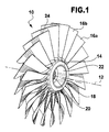
- FIG. 1 An embodiment of a rotor according to the invention, which is shown in FIG. 1 and denoted by 10 there, extends parallel to one Axial axis 12, which coincides with a rotor axis of rotation.
- the rotor 10 has a hub 14 and arranged on the hub 14 blades 16 a, 16 b, etc. on.
- the hub has an inner space 18 by means of which the rotor 10 can be placed on a shaft (not shown in the drawing).
- the interior 18 includes a first hollow cylindrical portion 20 through which the shaft is feasible.
- a second hollow-cylindrical region 22 follows the first region 20 and has a larger diameter than the first region 20. Via this second region 22, it is possible, for example, to fix the rotor 10 to the shaft.
- the formation and arrangement of the airfoils 16a, 16b, etc. on the hub 14 and the design of the hub 14 depends on the respective application.
- the rotor 10 is formed by a stack of a plurality of rotor elements 24 ( Figure 2).
- a rotor element 24 extends between a first one (Limiting) plane 26 and a second (limiting) plane 28.
- the distance between these two planes 26 and 28 corresponds to the thickness of a rotor element 24, wherein the two planes 26 and 28 are aligned parallel to each other. It can be provided that all the rotor elements 24 have the same thickness (the same distance between the planes 26 and 28). But it is also possible that different rotor elements 24 have different thicknesses.
- the first plane 26 and the second plane 28 are each perpendicular to the axial axis 12.
- a rotor element 24 typically includes a hub region 30 and airfoil regions 32. There may also be rotor elements, particularly outer rotor elements, which have only a hub region and no airfoil regions (to form a protruding hub part).
- the hub portions 30 and the airfoil portions 32 are integrally connected to each other.
- a rotor element 24 is preferably made of a metallic material such as titanium, at least with respect to its base (see below).
- the hub regions 30 and airfoil regions 32 of adjacent rotor elements 24 are adapted to one another such that the hub 14 and the airfoils 16 a, 16 b, etc. result from a stacking arrangement of all the rotor elements 24.
- Adjacent rotor elements 24 are connected to one another, for example, by soldering. Through the first plane 26 and the second plane 28, a correspondingly large surface area is provided for this planar connection.
- the rotor 10 is thus formed by a "stacking" of all rotor elements 24, which follow one another in the axial direction 12.
- the rotor elements 24 can be manufactured separately individually.
- Reinforcement regions 34 (FIG. 3), 36 (FIG. 4) can be provided on each or on selected rotor elements 24, as shown by way of example in FIGS. 3 and 4.
- a fiber-reinforced material is preferably arranged.
- it is a fiber-reinforced titanium material (TMC).
- TMC fiber-reinforced titanium material
- reinforcing regions 34 are provided, which extend between the airfoil regions 32 and the hub region 30 and thereby lie both in the hub region 30 and in the airfoil region 32.
- a reinforcement region 34 can be formed, for example, by forming a recess on a rotor element 24 in which the fiber-reinforced material is then positioned. Fibers are preferably arranged in the radial direction 38 perpendicular to the axial axis 12.
- the reinforcement region 36 serves to reinforce the hub region 30. It comprises a fiber-reinforced material which surrounds the axial axis 12 in the hub region 30. Fibers in the reinforcing region 36 are circular about this axial axis 12 in the hub region 30.
- one or more recesses 40 are produced in the rotor elements 24.
- a recess 40 serves to provide a cavity in the manufactured rotor 10. By providing cavities, the mass of the rotor 10 can be reduced.
- recesses 40 of adjacent rotor elements 24 are aligned with each other to provide one or more channels in the rotor 10. It is even possible in principle that channels are produced within blade blades 16a, 16b. By means of such channels, for example, a blow-out or an extraction on an airfoil 16a, 16b and / or on the hub 14 takes place.
- the rotor 10 is manufactured as follows:
- the rotor elements 24 are manufactured individually separately. For example, they are made of metal plates of a certain thickness (thus defining the first plane 26 and the second plane 28) by conventional metalworking techniques. The shaping of a corresponding rotor element 24 takes place in such a way that the hub 14 and the blades 16 a, 16 b result in a defined shape due to the composition of all the rotor elements in the stack composite 24.
- the airfoil portions 32 and the hub portion 30 are made in one-piece connection.
- the rotor elements 24 have boundary surfaces, the first plane 26 and the second plane 28.
- a planar connecting surface 42 (FIG. 3) is provided for connection to an adjacent rotor element 24. It can then achieve a surface connection.
- Adjacent rotor elements 24 can be connected to one another, for example by welding or adhesively.
- adjacent rotor elements 24 are joined together by soldering.
- the corresponding connection surfaces 42 are provided with solder and there is a Lötucunsher ein in an oven.
- the corresponding stack composite is mechanically processed, for example by sizing to produce the final contour.
- transitions between adjacent rotor elements can be smoothed.
- reinforcing regions 34 and 36 can be produced before the stacked composite is produced, by positioning a corresponding fiber composite material in corresponding recesses, which are produced, for example, by machining material.
- recesses 40 can be produced, for example, for the production of cavities or for the production of channels.
- a monolithic rotor 10 By stacking the rotor elements 24, a monolithic rotor 10 can be produced in a layered construction. It can be cavities (via recesses 40 in the individual rotor elements 24) bring in freely selectable positions. Thereby, a rotor 10 can be produced with a lower mass. Furthermore, the Hurdelungsth for the blades 16a, 16b, etc. can be improved without it can lead to increased loads.
- reinforcing areas in a targeted manner in order to provide reinforcement for particularly loaded directions.
- a radial reinforcement can be achieved via the reinforcement regions 34.
- the hub 14 can be amplified via the reinforcement regions 36.
- channels in the rotor 10 for example in the hub 14 and / or in the blades 16a, 16b.
- a rotor 10 with damage can be repaired in a simple manner.
- the damaged area is cut out with cuts parallel to connecting surfaces 42 (i.e., perpendicular to the axial direction 12). This can be done for example via wire EDM.
- the replacement area is then joined by attaching one or more rotor elements 24 (in an adapted form) to the remainder area (after cutting out the repair area) according to the method of manufacturing the rotor 10. It can be defined rotor levels with normal direction parallel to the axial axis 12 exchange.
- the rotor 10 may be used, for example, for a compressor impeller or a turbine impeller of an engine such as a missile engine.
Abstract
Description
Die Erfindung betrifft einen Rotor mit einer Nabe und an der Nabe angeordneten Schaufelblättern, welcher sich in einer Axialrichtung erstreckt, wobei die Axialrichtung koaxial zu einer Rotordrehachse ist, und welcher durch eine Zusammensetzung aus in Axialrichtung aufeinanderfolgenden Rotorelementen gebildet ist, wobei benachbarte Rotorelemente miteinander verbunden sind und die Rotorelemente einen Nabenbereich oder einen Nabenbereich und Schaufelblattbereiche aufweisen und die Kombination der Nabenbereiche und Schaufelblattbereiche der Rotorelemente die Nabe und die Schaufelblätter bilden.The invention relates to a rotor having a hub and arranged on the hub blades, which extends in an axial direction, wherein the axial direction is coaxial with a rotor axis of rotation, and which is formed by a composition of axially successive rotor elements, wherein adjacent rotor elements are interconnected and the rotor elements have a hub region or a hub region and airfoil regions, and the combination of the hub regions and airfoil regions of the rotor elements form the hub and the airfoils.
Die Erfindung betrifft ferner ein Verfahren zur Herstellung des Rotors, bei dem getrennte Rotorelemente mit einem Nabenbereich oder einem Nabenbereich und Schaufelblattbereichen hergestellt werden und die Rotorelemente in einer Axialrichtung zu einem Stapelverbund gefügt werden.The invention further relates to a method for manufacturing the rotor, wherein the separate rotor elements are manufactured with a hub region or a hub region and airfoil regions and the rotor elements are joined in an axial direction to form a stack composite.
Weiterhin betrifft die Erfindung ein Verfahren zur Reparatur eines Rotors mit einer Nabe und an der Nabe angeordneten Schaufelblättern, welcher sich in einer Axialrichtung erstreckt, wobei die Axialrichtung koaxial zu einer Rotordrehachse ist, und der Rotor aus in Axialrichtung aufeinanderfolgenden Rotorelementen zusammengesetzt ist, wobei benachbarte Rotorelemente miteinander verbunden sind und die Rotorelemente einen Nabenbereich oder einen Nabenbereich und Schaufelblattbereiche aufweisen und die Kombination der Nabenbereiche und Schaufelblattbereiche der Rotorelemente die Nabe und die Schaufelblätter bilden.Furthermore, the invention relates to a method for repairing a rotor having a hub and arranged on the hub blades, which extends in an axial direction, wherein the axial direction is coaxial with a rotor axis of rotation, and the rotor is composed of axially successive rotor elements, wherein adjacent rotor elements are interconnected and the rotor elements have a hub region or a hub region and airfoil regions, and the combination of the hub regions and airfoil regions of the rotor elements form the hub and the airfoils.
Aus dem Stand der Technik ist es bekannt, einen Rotor mit Nabe und Schaufelblättern durch Herausfräsen aus einem kompletten Block herzustellen.From the prior art it is known to produce a rotor with hub and blades by milling out of a complete block.
Es ist auch bekannt, die Schaufelblätter und die Nabe getrennt herzustellen, wobei dann die Schaufelblätter an der Nabe aufgeschweißt werden.It is also known to manufacture the airfoils and the hub separately, in which case the airfoils are welded to the hub.
Aus der
Aus der
Der Erfindung liegt die Aufgabe zugrunde, einen Rotor der eingangs genannten Art bereitzustellen, welcher sich auf einfache Weise mit optimierter Anbindung der Schaufelblätter an die Nabe herstellen lässt.The invention has for its object to provide a rotor of the type mentioned, which can be produced in a simple manner with optimized connection of the blades to the hub.
Diese Aufgabe wird bei dem eingangs genannten Rotor erfindungsgemäß dadurch gelöst, dass ein Rotorelement einen oder mehrere Verstärkungsbereiche aufweist und dass ein Verstärkungsbereich sich von einem Schaufelblattbereich in einen Nabenbereich erstreckt und/oder in einem Nabenbereich angeordnet ist.This object is achieved according to the invention in the rotor mentioned above in that a rotor element has one or more reinforcement regions and that a reinforcement region extends from an airfoil region into a hub region and / or is arranged in a hub region.
Die Rotorelemente lassen sich getrennt herstellen und optimieren. Beispielsweise lassen sich gezielt Verstärkungsbereiche mit definierter Verstärkungsrichtung in die Rotorelemente integrieren. In einem Rotorelement erfolgt im wesentlichen keine Kraftflussunterbrechung.The rotor elements can be manufactured and optimized separately. For example, it is possible to integrate reinforcing regions with a defined reinforcing direction into the rotor elements in a targeted manner. In a rotor element is essentially no power flow interruption.
Die Fügung benachbarter Rotorelemente erfolgt über Verbindungsflächen, die eine sehr geringe Belastung erfahren. Diese liegen insbesondere senkrecht zur Axialrichtung (und damit zur Rotordrehachse). Durch die Fügung wird die Betriebsfestigkeit nicht wesentlich beeinträchtigt.The joining of adjacent rotor elements via connecting surfaces, which experience a very low load. These are in particular perpendicular to the axial direction (and thus to the rotor axis of rotation). The addition does not significantly affect the fatigue life.
Der Rotor ist aus scheibenförmigen Elementen (nämlich den Rotorelementen) zusammengesetzt, wobei in diese scheibenförmigen Elemente über die Schaufelblattbereiche der entsprechende Schaufelblattanteil bereits integriert ist. Dadurch ist eine Fixierung eines ganzen Schaufelblatts an der Nabe nicht notwendig.The rotor is composed of disk-shaped elements (namely the rotor elements), wherein the corresponding blade leaf portion is already integrated into these disk-shaped elements via the blade blade areas. As a result, a fixation of a whole airfoil on the hub is not necessary.
Da die einzelnen Rotorelemente individuell herstellbar sind, lassen sich beispielsweise auch Ausnehmungen einbringen, über die sich Hohlräume in dem Rotor bilden lassen. Dadurch lässt sich dessen Masse verringern und die Massenverteilung definiert einstellen. Über die Einbringung von Ausnehmungen lassen sich auch gezielt Kanäle ausbilden, um beispielsweise eine Ausblasung oder Absaugung an dem Rotor erreichen zu können.Since the individual rotor elements can be produced individually, it is also possible, for example, to introduce recesses over which cavities can be formed in the rotor. This can reduce its mass and set the mass distribution defined. About the introduction of recesses can also form targeted channels, for example, to achieve a blow or suction on the rotor can.
Ein Rotorelement lässt sich auch aus unterschiedlichen Materialien herstellen. Beispielsweise werden höher belastete Bereiche aus einem Material höherer Festigkeit hergestellt.A rotor element can also be produced from different materials. For example, higher loaded areas are made from a higher strength material.
Mit der erfindungsgemäßen Lösung lässt sich ein monolithischer Rotor bereitstellen, welcher nicht aus einem monolithischen Block hergestellt ist.The solution according to the invention makes it possible to provide a monolithic rotor which is not made from a monolithic block.
Weiterhin lässt sich eine Reparatur auf einfache Weise durchführen, da ein zu reparierender Bereich herausgeschnitten werden kann und ein Austauschbereich durch einfache Weise über ein oder mehrere Rotorelemente definiert werden kann und damit über ein oder mehrere Rotorelemente hergestellt werden kann.Furthermore, a repair can be carried out in a simple manner, since a region to be repaired can be cut out and an exchange region can be defined in a simple manner via one or more rotor elements and thus can be manufactured via one or more rotor elements.
Ein Rotorelement weist einen oder mehrere Verstärkungsbereiche auf. Es lassen sich dadurch besonders belastete Bereiche gezielt verstärken. Beispielsweise lässt sich in radialer Richtung die Verbindung eines Schaufelblattbereichs mit einem Nabenbereich über einen Verstärkungsbereich zusätzlich verstärken, um das Abbrechen eines Schaufelblatts zu erschweren.A rotor element has one or more reinforcement regions. This makes it possible to selectively reinforce particularly stressed areas. For example, in the radial direction, the connection of an airfoil region to a hub region via a reinforcing region can be additionally reinforced in order to make it more difficult to break off an airfoil.
Es ist vorgesehen, dass ein Verstärkungsbereich sich von einem Schaufelblattbereich in einen Nabenbereich erstreckt. Dadurch lässt sich die Verbindung von Schaufelblättern mit der Nabe verstärken.It is envisaged that a reinforcement region extends from an airfoil region into a hub region. This allows the connection of blades with the hub reinforce.
Es kann alternativ oder zusätzlich ein Verstärkungsbereich im Nabenbereich angeordnet sein, um die Nabe zu verstärken.Alternatively or additionally, a reinforcement region may be arranged in the hub region in order to reinforce the hub.
Insbesondere erstrecken sich Rotorelemente zwischen einer ersten Ebene und einer zweiten Ebene. Diese Ebenen bilden Begrenzungsflächen für die Rotorelemente und definieren dadurch eine ebene Oberseite und eine ebene Unterseite. Ein Rotorelement kann Bereiche aufweisen, welche gegenüber der ersten und/oder zweiten Ebene zurückgesetzt sind. Die einzelnen Rotorelemente lassen sich auf einfache Weise beispielsweise aus einer Platte herstellen. Die einzelnen Rotorelemente weisen selber mindestens teilweise ebene Oberflächen auf. Dadurch lässt sich auf einfache Weise eine Verbindung zwischen benachbarten Rotorelementen herstellen. Weiterhin lässt sich dadurch eine Verbindungsfläche realisieren, welche senkrecht zu der Axialrichtung angeordnet ist. Ein dadurch realisierter Verbindungsbereich in einem Stapelverbund des Rotors ist geringen Belastungen ausgesetzt.In particular, rotor elements extend between a first plane and a second plane. These planes form boundary surfaces for the rotor elements and thereby define a flat top and a flat bottom. A rotor element may have regions that are set back relative to the first and / or second plane. The individual rotor elements can be produced in a simple manner, for example from a plate. The individual rotor elements themselves have at least partially planar surfaces. This makes it easy to establish a connection between adjacent rotor elements. Furthermore, can thereby realize a connection surface which is arranged perpendicular to the axial direction. A connecting region realized thereby in a stacked assembly of the rotor is exposed to low loads.
Insbesondere sind die erste Ebene und die zweite Ebene parallel zueinander. Dadurch lässt sich eine strenge Ausrichtung der Rotorelemente senkrecht zur Axialrichtung erreichen.In particular, the first level and the second level are parallel to each other. This makes it possible to achieve a strict alignment of the rotor elements perpendicular to the axial direction.
Günstig ist es, wenn die erste Ebene senkrecht zur Axialrichtung liegt. Dadurch sind die Kraftbelastungen des Verbindungsbereichs zwischen benachbarten Rotorelementen gering.It is favorable if the first plane is perpendicular to the axial direction. As a result, the force loads of the connection area between adjacent rotor elements are low.
Aus dem gleichen Grund ist es günstig, wenn die zweite Ebene senkrecht zur Axialrichtung liegt.For the same reason, it is favorable if the second plane is perpendicular to the axial direction.
Insbesondere ist der Abstand zwischen der ersten Ebene und der zweiten Ebene kleiner als der Radius der Nabe. Die Rotorelemente lassen sich dann auf einfache Weise aus Platten herstellen, wobei sich auf einfache Weise eine entsprechende dreidimensionale Formung der Schaufelblätter erreichen lässt.In particular, the distance between the first plane and the second plane is smaller than the radius of the hub. The rotor elements can then be produced in a simple manner from plates, wherein a corresponding three-dimensional shaping of the blades can be achieved in a simple manner.
Insbesondere werden die Rotorelemente getrennt hergestellt, d. h. einzelne Rotorelemente werden individuell hergestellt. Durch die Fügung ergeben sich dann die Nabe und die Schaufelblätter mit ihrer speziellen geometrischen Form.In particular, the rotor elements are manufactured separately, d. H. individual rotor elements are manufactured individually. By the addition then the hub and the blades with their special geometric shape arise.
Ganz besonders vorteilhaft ist es, wenn ein Nabenbereich und Schaufelblattbereiche eines Rotorelements einstückig miteinander verbunden sind. Dadurch lässt sich bezogen auf ein Rotorelement eine hohe Festigkeit erreichen. Der Kraftfluss innerhalb eines Rotorelements wird nicht unterbrochen.It is particularly advantageous if a hub region and airfoil regions of a rotor element are integrally connected to one another. As a result, a high strength can be achieved with respect to a rotor element. The flow of force within a rotor element is not interrupted.
Günstig ist es, wenn die Nabe durch eine Reihe von in Axialrichtung aufeinanderfolgenden Nabenbereichen gebildet ist. Mit dem Stapelverbund der Rotorelement wird die Nabe geformt.It is advantageous if the hub is formed by a series of axially successive hub areas. With the stack composite of the rotor element, the hub is formed.
Günstigerweise ist ein Schaufelblatt durch eine Reihe von in Axialrichtung aufeinanderfolgenden Schaufelblattbereichen gebildet. Die dreidimensionale Ausformung eines Schaufelblatts wird durch Anordnung und Ausbildung von Schaufelblattbereichen an den entsprechenden Rotorelementen gebildet.Conveniently, an airfoil is formed by a series of axially consecutive airfoil regions. The three-dimensional formation of an airfoil is formed by arranging and forming airfoil regions on the respective rotor elements.
Es ist vorgesehen, dass die Rotorelemente mindestens bezüglich eines Grundkörpers aus einem metallischen Material hergestellt sind. Ein solches metallisches Material wie beispielsweise Titan weist die erforderliche Festigkeit auf und lässt sich auf einfache Weise bearbeiten. Ein Rotorelement muss bezüglich des Materials nicht unbedingt homogen ausgebildet sein. Es kann dabei zusätzlich vorgesehen sein, dass eine Verstärkung des metallischen Materials durch ein faserverstärktes Material wie beispielsweise TMC (Titan Matrix Composite) erfolgt. Die Fasern bestehen beispielsweise aus SiC.It is provided that the rotor elements are made at least with respect to a base body of a metallic material. Such a metallic material such as titanium has the required strength and can be processed easily. A rotor element need not necessarily be homogeneously formed with respect to the material. It may additionally be provided that a reinforcement of the metallic material by a fiber-reinforced material such as TMC (titanium matrix composite) takes place. The fibers are made of SiC, for example.
Es ist grundsätzlich auch denkbar, dass ein Rotorelement insbesondere vollständig aus einem Faserverbundwerkstoff hergestellt ist.In principle, it is also conceivable that a rotor element is in particular made entirely of a fiber composite material.
Günstig ist es, wenn in einem Verstärkungsbereich ein faserverstärktes Material angeordnet ist. Durch die Faserorientierung insbesondere von Langfasern oder Endlosfasern lässt sich eine gezielte Verstärkung in bestimmten Richtungen erreichen, um die Festigkeit in bestimmten Richtungen zu erhöhen. Ein Verstärkungsbereich ist beispielsweise als Inlet ausgebildet, bei dem in einer Ausnehmung des Rotorelements ein Verstärkungsmaterial angeordnet ist.It is favorable if a fiber-reinforced material is arranged in a reinforcement region. Due to the fiber orientation, in particular of long fibers or continuous fibers, a targeted reinforcement in certain directions can be achieved in order to increase the strength in certain directions. A reinforcing region is formed, for example, as an inlet, in which a reinforcing material is arranged in a recess of the rotor element.
Beispielsweise ist ein Verstärkungsbereich in einem Schaufelblattbereich angeordnet, um eine Verstärkung in den Schaufelblättern zu erreichen.For example, a reinforcement region is disposed in an airfoil region to achieve reinforcement in the airfoils.
Beispielsweise umgibt ein Verstärkungsbereich die Axialrichtung. Durch Fasern wird die Axialrichtung gewissermaßen umwickelt. Dadurch lässt sich eine Umfangsverstärkung der Nabe erreichen.For example, a gain region surrounds the axial direction. By fibers, the axial direction is wrapped in a sense. As a result, a circumferential reinforcement of the hub can be achieved.
Ganz besonders vorteilhaft ist es, wenn benachbarte Rotorelemente flächig miteinander verbunden sind. Dadurch lässt sich eine feste Fügeverbindung der Rotorelemente in dem Rotor erreichen.It is particularly advantageous if adjacent rotor elements are connected to one another in a flat manner. As a result, a fixed joint connection of the rotor elements in the rotor can be achieved.
Günstig ist es, wenn benachbarte Rotorelemente durch Lötung oder durch Schweißung (beispielsweise Diffusionsschweißung) oder adhäsiv miteinander verbunden sind. Insbesondere wenn die Rotorelemente aus einem metallischen Material hergestellt sind, lässt sich auf einfache Weise eine Verbindung beispielsweise über Lötung erreichen. Diese Lötverbindung lässt sich beispielsweise dadurch herstellen, dass Lot auf eine Verbindungsfläche aufgetragen wird und Rotorelemente in einem Stapelverbund in einen Ofen gegeben werden.It is favorable if adjacent rotor elements are joined together by soldering or by welding (for example diffusion welding) or adhesively. In particular, when the rotor elements are made of a metallic material, can be a connection in a simple manner for example, achieve over soldering. This solder joint can be produced, for example, by applying solder to a bonding surface and placing rotor elements in a stack assembly in an oven.
Insbesondere ist eine Verbindungsfläche für die Verbindung benachbarter Rotorelemente senkrecht zur Axialrichtung orientiert. Über solche Verbindungsflächen (die vorzugsweise eben sind) ist der Kraftfluss (parallel zur Axialrichtung) relativ gering, so dass sich eine hohe Festigkeit in dem Stapelverbund erreichen lässt.In particular, a connection surface for the connection of adjacent rotor elements is oriented perpendicular to the axial direction. By means of such connection surfaces (which are preferably flat), the force flow (parallel to the axial direction) is relatively low, so that a high strength can be achieved in the stack assembly.
Es kann vorgesehen sein, dass ein Rotorelement mindestens eine Ausnehmung aufweist. Eine solche Ausnehmung lässt sich auf einfache Weise an einem Rotorelement herstellen. Über eine Ausnehmung oder eine Mehrzahl von Ausnehmungen lassen sich beispielsweise Hohlräume in dem Rotor ausbilden, die bei aus dem Stand der Technik bekannten Rotoren so nicht herstellbar sind. Durch solche Hohlräume lässt sich die Masse verringern und eine definierte Massenverteilung einstellen. Beispielsweise können solche hergestellten Hohlräume auch dann genutzt werden, ein definiertes Dämpfungsverhalten einzustellen, insbesondere wenn in Hohlräumen ein entsprechendes dämpfungsbeeinflussendes Material gelagert wird. Ausnehmungen können auch so fluchtend zueinander angeordnet sein, dass Kanäle innerhalb des Rotors ausgebildet sind. Die Kanäle können in der Nabe oder in Schaufelblättern angeordnet sein, um beispielsweise eine Absaugung oder eine Ausblasung zu ermöglichen.It can be provided that a rotor element has at least one recess. Such a recess can be produced in a simple manner on a rotor element. For example, cavities can be formed in the rotor via a recess or a plurality of recesses, which cavities can not be produced in rotors known from the prior art. Through such cavities, the mass can be reduced and set a defined mass distribution. For example, such produced cavities can also be used to set a defined damping behavior, especially if a corresponding damping-influencing material is stored in cavities. Recesses may also be arranged in alignment with each other so that channels are formed within the rotor. The channels may be disposed in the hub or in airfoils to facilitate, for example, suction or blow-out.
Günstigerweise ist eine Stapelverbindung einer Mehrzahl von in Axialrichtung aufeinanderfolgenden Rotorelementen vorgesehen, durch welche der Rotor gebildet ist.Conveniently, a stack connection of a plurality of axially successive rotor elements is provided, through which the rotor is formed.
Der Erfindung liegt ferner die Aufgabe zugrunde, ein Verfahren zur Herstellung eines Rotors der eingangs genannten Art mit optimierter Naben-Schaufelblatt-Verbindung bereitzustellen.The invention is further based on the object to provide a method for producing a rotor of the type mentioned with optimized hub-blade connection.
Diese Aufgabe wird erfindungsgemäß dadurch gelöst, dass ein Rotorelement mit einem oder mehreren Verstärkungsbereichen versehen wird, welche sich von einem Schaufelblattbereich in einen Nabenbereich erstrecken.This object is achieved according to the invention in that a rotor element is provided with one or more reinforcement regions, which extend from an airfoil region into a hub region.
Durch die erfindungsgemäße Lösung lässt sich ein monolithischer Rotor herstellen, welcher nicht aus einem monolithischen Block herausgefräst werden muss.The solution according to the invention makes it possible to produce a monolithic rotor which does not have to be milled out of a monolithic block.
Weitere Vorteile des erfindungsgemäßen Verfahrens wurden bereits im Zusammenhang mit dem erfindungsgemäßen Rotor erläutert.Further advantages of the method according to the invention have already been explained in connection with the rotor according to the invention.
Weitere vorteilhafte Ausgestaltungen des erfindungsgemäßen Verfahrens wurden ebenfalls bereits im Zusammenhang mit dem erfindungsgemäßen Rotor erläutert.Further advantageous embodiments of the method according to the invention have also already been explained in connection with the rotor according to the invention.
Insbesondere werden benachbarte Rotorelemente miteinander verbunden. Dadurch lässt sich ein Stapelverbund herstellen.In particular, adjacent rotor elements are connected together. This can be a stack composite produce.
Rotorelemente lassen sich durch Lötung, Schweißung (beispielsweise Diffusionsschweißung) oder adhäsiv miteinander verbinden. Insbesondere wenn die Rotorelemente aus einem metallischen Material hergestellt sind, lässt sich eine Verbindung auf einfache Weise durch Lötung erreichen.Rotor elements can be joined together by soldering, welding (for example diffusion welding) or adhesively. In particular, when the rotor elements are made of a metallic material, a connection can be easily achieved by soldering.
Günstig ist es, wenn Rotorelemente flächig miteinander verbunden werden. Dadurch lässt sich ein sicherer Stapelverbund zur Bildung eines monolithischen Rotors herstellen.It is advantageous if rotor elements are connected to each other flat. This allows a secure stack composite to form a monolithic rotor produce.
Günstigerweise werden Schaufelblattbereiche an den jeweiligen Rotorelementen individuell geformt. Durch die Kombination von entsprechenden Schaufelblattbereichen lassen sich Schaufelblätter in ihrer 3D-Ausformung herstellen.Conveniently, airfoil portions are individually formed on the respective rotor elements. The combination of corresponding airfoil sections makes it possible to produce airfoils in their 3D shape.
Besonders vorteilhaft ist es, wenn der Nabenbereich und die Schaufelblattbereiche eines Rotors einstückig miteinander verbunden hergestellt werden. Beispielsweise wird das entsprechende Rotorelement durch bekannte Metallbearbeitungsverfahren aus einer Metallplatte hergestellt. Dadurch ist ein nicht unterbrochener Kraftfluss zwischen dem Nabenbereich und den Schaufelblattbereichen und dadurch beim hergestellten Rotor zwischen der Nabe und den Schaufelblättern senkrecht zur Rotordrehachse sichergestellt. Auch die Herstellung ist vereinfacht.It is particularly advantageous if the hub region and the blade leaf regions of a rotor are produced integrally with one another. For example, the corresponding rotor element is made by known metal working methods from a metal plate. As a result, an uninterrupted flow of force between the hub region and the airfoil regions, and thereby the produced rotor between the hub and the blades is ensured perpendicular to the rotor axis of rotation. The production is simplified.
Es kann vorgesehen sein, dass an einem Rotorelement eine oder mehrere Ausnehmungen hergestellt werden. Diese können beispielsweise dazu dienen, ein faserverstärktes Material zur Herstellung von Verstärkungsbereichen aufzunehmen. Über Ausnehmungen lassen sich auch Hohlräume oder Kanäle ausbilden.It can be provided that one or more recesses are produced on a rotor element. These may serve, for example, to receive a fiber-reinforced material for the production of reinforcement areas. Recesses can also form cavities or channels.
Ein Rotorelement wird mit einem oder mehreren Verstärkungsbereichen versehen. Durch das Versehen mit Verstärkungsbereichen wird die Verbindungsmöglichkeit benachbarter Rotorelemente nicht wesentlich beeinträchtigt. Die Verstärkungsbereiche lassen sich gezielt an den relevanten Stellen anordnen.A rotor element is provided with one or more reinforcement regions. By providing with reinforcement areas, the possibility of connecting adjacent rotor elements is not significantly impaired. The amplification areas can be arranged in a targeted manner at the relevant locations.
Um glatte Übergänge zu erreichen, ist es vorteilhaft, wenn eine Endkonturbearbeitung an einem Stapelverbund oder Schichtverbund von Rotorelementen erfolgt. Beispielsweise handelt es sich um eine Schlichtbearbeitung.In order to achieve smooth transitions, it is advantageous if a final contour machining takes place on a stacked composite or layer composite of rotor elements. For example, it is a finishing.
Der Erfindung liegt ferner die Aufgabe zugrunde, ein Reparaturverfahren der eingangs genannten Art bereitzustellen, welches sich auf einfache Weise durchführen lässt.The invention is further based on the object to provide a repair method of the type mentioned, which can be carried out in a simple manner.
Diese Aufgabe wird erfindungsgemäß dadurch gelöst, dass ein Reparaturbereich des Rotors mit einer Schnittebene senkrecht zur Axialrichtung herausgeschnitten wird und ein Austauschbereich durch ein oder mehrere Rotorelemente hergestellt wird.This object is achieved in that a repair region of the rotor is cut out with a sectional plane perpendicular to the axial direction and an exchange region is made by one or more rotor elements.
Bei dem genannten Rotor lässt sich auf einfache Weise eine Reparatur durchführen, da der Rotor durch einen Stapelverbund von in Axialrichtung aufeinanderfolgenden Rotorelementen gebildet ist. Ein entsprechender Reparaturbereich lässt sich dadurch auf einfache Weise entfernen und ein entsprechender Austauschbereich lässt sich auf einfache Weise über Rotorelemente ausbilden.In the case of said rotor, a repair can be carried out in a simple manner, since the rotor is formed by a stack of axially successive rotor elements. A corresponding repair area can be removed in a simple manner and a corresponding exchange area can be formed in a simple manner via rotor elements.
Insbesondere erfolgt ein Schnitt an einem Übergangsbereich zwischen benachbarten Rotorelementen. Dadurch lässt sich der Austausch auf einfache Weise durchführen, da der Austauschbereich dann ein ganzzahliges (einschließlich Eins) Vielfaches der Dicke von Rotorelementen ist.In particular, a cut takes place at a transition region between adjacent rotor elements. This makes it easy to perform the replacement because the exchange area is then an integer (including one) multiple of the thickness of rotor elements.
Beispielsweise wird ein Reparaturbereich über Drahterosion herausgeschnitten. Durch Drahterosion lässt sich ein Reparaturbereich mit einer definierten Schnittebene heraustrennen.For example, a repair area is cut out by wire erosion. Wire erosion can be used to cut out a repair area with a defined cutting plane.
Die nachfolgende Beschreibung bevorzugter Ausführungsformen dient im Zusammenhang mit der Zeichnung der näheren Erläuterung der Erfindung. Es zeigen:
- Figur 1
- eine perspektivische Darstellung eines Ausführungsbeispiels eines erfindungsgemäßen Rotors;
- Figur 2
- eine Explosionsdarstellung des Rotors gemäß Figur 1 (entsprechend einer Veranschaulichung eines Zwischenschritts bei dem Herstellungsverfahren des Rotors gemäß Figur 1);
- Figur 3
- ein erstes Ausführungsbeispiel eines Rotorelements; und
- Figur 4
- ein zweites Ausführungsbeispiel eines Rotorelements.
- FIG. 1
- a perspective view of an embodiment of a rotor according to the invention;
- FIG. 2
- an exploded view of the rotor according to Figure 1 (corresponding to an illustration of an intermediate step in the manufacturing method of the rotor according to Figure 1);
- FIG. 3
- a first embodiment of a rotor element; and
- FIG. 4
- a second embodiment of a rotor element.
Ein Ausführungsbeispiel eines erfindungsgemäßen Rotors, welches in Figur 1 gezeigt und dort mit 10 bezeichnet ist, erstreckt sich parallel zu einer Axialachse 12, welche mit einer Rotordrehachse zusammenfällt. Der Rotor 10 weist eine Nabe 14 und an der Nabe 14 angeordnete Schaufelblätter 16a, 16b usw. auf.An embodiment of a rotor according to the invention, which is shown in FIG. 1 and denoted by 10 there, extends parallel to one
Die Nabe weist bei dem gezeigten Ausführungsbeispiel einen Innenraum 18 auf, mittels dem sich der Rotor 10 auf eine Welle (in der Zeichnung nicht gezeigt) aufsetzen lässt. Beispielsweise umfasst der Innenraum 18 einen ersten hohlzylindrischen Bereich 20, durch den die Welle durchführbar ist. Ein zweiter hohlzylindrischer Bereich 22 folgt auf den ersten Bereich 20 und hat einen größeren Durchmesser als der erste Bereich 20. Über diesen zweiten Bereich 22 lässt sich beispielsweise eine Fixierung des Rotors 10 an der Welle erreichen.In the exemplary embodiment shown, the hub has an
Die Ausbildung und Anordnung der Schaufelblätter 16a, 16b usw. an der Nabe 14 sowie die Ausbildung der Nabe 14 hängt von der entsprechenden Anwendung ab.The formation and arrangement of the
Der Rotor 10 ist durch einen Stapelverbund einer Mehrzahl von Rotorelementen 24 gebildet (Figur 2).The
Ein Rotorelement 24 erstreckt sich zwischen einer ersten
(Begrenzungs-)Ebene 26 und einer zweiten (Begrenzungs-)Ebene 28. Der Abstand dieser beiden Ebenen 26 und 28 entspricht der Dicke eines Rotorelements 24, wobei die beiden Ebenen 26 und 28 parallel zueinander ausgerichtet sind. Es kann vorgesehen sein, dass alle Rotorelemente 24 die gleiche Dicke (den gleichen Abstand zwischen den Ebenen 26 und 28) aufweisen. Es ist aber auch möglich, dass unterschiedliche Rotorelemente 24 unterschiedliche Dicken aufweisen.A
(Limiting)
Die erste Ebene 26 und die zweite Ebene 28 liegen jeweils senkrecht zur Axialachse 12.The
Ein Rotorelement 24 umfasst typischerweise einen Nabenbereich 30 und Schaufelblattbereiche 32. Es kann auch Rotorelemente geben, und zwar insbesondere äußere Rotorelemente, welche nur einen Nabenbereich und keine Schaufelblattbereiche aufweisen (zur Bildung eines überstehenden Nabenteils).A
Die Nabenbereiche 30 und die Schaufelblattbereiche 32 sind einstückig miteinander verbunden.The
Ein Rotorelement 24 ist mindestens bezüglich seines Grundkörpers (siehe unten) vorzugsweise aus einem metallischen Material wie beispielsweise Titan hergestellt.A
Die Nabenbereiche 30 und Schaufelblattbereiche 32 benachbarter Rotorelemente 24 sind angepasst aneinander ausgebildet, so dass sich durch einen Stapelverbund aller Rotorelemente 24 die Nabe 14 und die Schaufelblätter 16a, 16b usw. ergeben.The
Benachbarte Rotorelemente 24 sind beispielsweise über Lötung flächig miteinander verbunden. Durch die erste Ebene 26 und die zweite Ebene 28 wird ein entsprechend großer Flächenbereich zu dieser flächigen Verbindung bereitgestellt.
Der Rotor 10 ist somit durch eine "Stapelung" aller Rotorelemente 24, welche in der Axialrichtung 12 aufeinanderfolgen, gebildet.The
Die Rotorelemente 24 lassen sich getrennt individuell herstellen.The
Es können an jedem oder an ausgewählten Rotorelementen 24, wie in den Figuren 3 und 4 beispielhaft gezeigt, Verstärkungsbereiche 34 (Figur 3), 36 (Figur 4) vorgesehen sein. In einem solchen Verstärkungsbereich ist bevorzugterweise ein faserverstärktes Material angeordnet. Beispielsweise handelt es sich um ein faserverstärktes Titanmaterial (TMC). Die Fasern sind dabei in einer solchen Orientierung angeordnet, dass eine gezielte Verstärkung erreicht wird.Reinforcement regions 34 (FIG. 3), 36 (FIG. 4) can be provided on each or on selected
Beispielsweise sind Verstärkungsbereiche 34 vorgesehen, welche zwischen den Schaufelblattbereichen 32 und dem Nabenbereich 30 verlaufen und dabei sowohl in dem Nabenbereich 30 als auch in dem Schaufelblattbereich 32 liegen. Ein solcher Verstärkungsbereich 34 lässt sich beispielsweise dadurch ausbilden, dass eine Ausnehmung an einem Rotorelement 24 hergestellt wird, in welchem dann das faserverstärkte Material positioniert wird. Fasern sind dabei vorzugsweise in Radialrichtung 38 senkrecht zur Axialachse 12 angeordnet.For example, reinforcing
Bei dem in Figur 4 gezeigten Ausführungsbeispiel eines Rotorelements dient der Verstärkungsbereich 36 zur Verstärkung des Nabenbereichs 30. Er umfasst ein faserverstärktes Material, welches die Axialachse 12 in dem Nabenbereich 30 umgibt. Fasern in dem Verstärkungsbereich 36 liegen kreisförmig um diese Axialachse 12 in dem Nabenbereich 30.In the exemplary embodiment of a rotor element shown in FIG. 4, the
Es kann vorgesehen sein, dass in den Rotorelementen 24 eine oder mehrere Ausnehmungen 40 hergestellt werden. Beispielsweise dient eine solche Ausnehmung 40 dazu, in dem hergestellten Rotor 10 einen Hohlraum bereitzustellen. Durch das Vorsehen von Hohlräumen lässt sich die Masse des Rotors 10 reduzieren.It can be provided that one or
Es ist auch möglich, dass Ausnehmungen 40 benachbarter Rotorelemente 24 fluchtend miteinander ausgerichtet werden, um einen oder mehrere Kanäle in dem Rotor 10 bereitzustellen. Es ist dabei sogar grundsätzlich möglich, dass Kanäle innerhalb von Schaufelblättern 16a, 16b hergestellt werden. Über solche Kanäle kann beispielsweise eine Ausblasung oder eine Absaugung an einem Schaufelblatt 16a, 16b und/oder an der Nabe 14 erfolgt.It is also possible that recesses 40 of
Die Rotorelemente 24 werden individuell getrennt hergestellt. Beispielsweise werden sie aus Metallplatten einer bestimmten Dicke (wodurch dann die erste Ebene 26 und die zweite Ebene 28 definiert sind) durch übliche Metallbearbeitungsverfahren herausgearbeitet. Die Formgebung eines entsprechenden Rotorelements 24 erfolgt dabei derart, dass sich durch die Zusammensetzung aller Rotorelemente in dem Stapelverbund 24 die Nabe 14 und die Schaufelblätter 16a, 16b in einer definierten Form ergeben.The
Bei der Herstellung des Rotorelements 24 werden die Schaufelblätterbereiche 32 und der Nabenbereich 30 mit einer einstückigen Verbindung hergestellt.In the manufacture of the
Die Rotorelemente 24 weisen, wie oben erwähnt, Begrenzungsflächen, die erste Ebene 26 und die zweite Ebene 28, auf. Dadurch ist eine ebene Verbindungsfläche 42 (Figur 3) zur Verbindung mit einem benachbarten Rotorelement 24 bereitgestellt. Es lässt sich dann eine flächige Verbindung erreichen.As mentioned above, the
Nach der Herstellung der individuellen Rotorelemente 24 werden diese zu einem Stapelverbund verbunden. Benachbarte Rotorelemente 24 können beispielsweise durch Schweißung oder adhäsiv miteinander verbunden werden.After the manufacture of the
Bei einer vorteilhaften Ausführungsform werden benachbarte Rotorelemente 24 durch Lötung miteinander verbunden. Dazu werden die entsprechenden Verbindungsflächen 42 mit Lot versehen und es erfolgt eine Lötverbindungsherstellung in einem Ofen.In an advantageous embodiment,
Der entsprechende Stapelverbund wird mechanisch bearbeitet, beispielsweise durch Schlichtung, um die Endkontur herzustellen. Dadurch lassen sich insbesondere Übergänge zwischen benachbarten Rotorelementen glätten.The corresponding stack composite is mechanically processed, for example by sizing to produce the final contour. As a result, in particular transitions between adjacent rotor elements can be smoothed.
An den einzelnen Rotorelementen 24 können vor der Herstellung des Stapelverbundes Verstärkungsbereiche 34 bzw. 36 hergestellt werden, indem in entsprechende Ausnehmungen, welche beispielsweise durch spanabhebende Materialverarbeitung hergestellt werden, ein entsprechendes Faserverbundmaterial positioniert wird.At the
Ebenso können Ausnehmungen 40 beispielsweise zur Hohlraumherstellung oder zur Herstellung von Kanälen hergestellt werden.Likewise, recesses 40 can be produced, for example, for the production of cavities or for the production of channels.
Bei dem Rotor 10 sind benachbarte Rotorelemente 24 über Verbindungsflächen 42 verbunden, welche senkrecht zur Axialachse 12 liegen. Die Fügung erfolgt also auf einer Fläche senkrecht zur Axialrichtung 12 und nicht über Flächen mit radialer Normalenrichtung bzw. Normalenrichtung, welche in einer Umfangsrichtung liegt. Senkrecht zu der Axialachse 12 sind die Belastungen bei der Rotation des Rotors 10 relativ gering. Durch den Stapelverbund lässt sich daher ein hohes Festigkeitspotential bei einfacher Herstellbarkeit erreichen.In the
Durch den Stapelverbund der Rotorelemente 24 lässt sich ein monolithischer Rotor 10 in einer Schichtbauweise herstellen. Es lassen sich Hohlräume (über Ausnehmungen 40 in den einzelnen Rotorelementen 24) an frei wählbaren Positionen einbringen. Dadurch kann ein Rotor 10 mit geringerer Masse hergestellt werden. Weiterhin lassen sich die Fädelungsmöglichkeiten für die Schaufelblätter 16a, 16b usw. verbessern, ohne dass es zu erhöhten Lasten kommen kann.By stacking the
Weiterhin lassen sich gezielt Verstärkungsbereiche herstellen, um eine Verstärkung für besonders belastete Richtungen bereitzustellen. Beispielsweise lässt sich über die Verstärkungsbereiche 34 eine radiale Verstärkung erreichen. Über die Verstärkungsbereiche 36 lässt sich die Nabe 14 verstärken.Furthermore, it is possible to produce reinforcing areas in a targeted manner in order to provide reinforcement for particularly loaded directions. For example, a radial reinforcement can be achieved via the
Es ist möglich, in dem Rotor 10 gezielt Kanäle beispielsweise in der Nabe 14 und/oder in den Schaufelblättern 16a, 16b anzuordnen.It is possible to specifically arrange channels in the
Ein Rotor 10 mit Beschädigungen lässt sich auf einfache Weise reparieren. Der beschädigte Bereich wird dazu mit Schnitten parallel zu Verbindungsflächen 42 (d. h. senkrecht zur Axialrichtung 12) herausgeschnitten. Dies kann beispielsweise über Drahterodieren erfolgen. Der Ersatzbereich wird dann durch Anfügung eines oder mehrerer Rotorelemente 24 (in angepasster Form) an den Restbereich (nach Herausschneiden des Reparaturbereichs) entsprechend dem Verfahren bei der Herstellung des Rotors 10 gefügt. Es lassen sich definiert Rotorebenen mit Normalenrichtung parallel zur Axialachse 12 austauschen.A
Das Problem der Anbindung von Schaufelblättern 16a, 16b an die Nabe 14 ist verringert, da die Schaufelblattbereiche 32 einstückig an dem Nabenbereich 30 für jedes Rotorelement 24 ausbildbar sind. Innerhalb eines Rotorelements 24 ist der Kraftfluss nicht unterbrochen. Der Kraftfluss zwischen benachbarten Rotorelementen 24 (welcher parallel zur Axialachse 12 verläuft) ist dagegen so gering, dass nicht erwartet wird, dass die Betriebsfestigkeit sich verschlechtert.The problem of connecting
Der Rotor 10 lässt sich beispielsweise für ein Verdichterlaufrad oder ein Turbinenlaufrad eines Triebwerks wie beispielsweise eines Flugkörpertriebwerks einsetzen.The
Claims (33)
dadurch gekennzeichnet , dasseinRotorelement(24) einen oder mehrere Verstärkungsbereiche (34; 36) aufweist und dass ein Verstärkungsbereich (34; 36) sich von einem Schaufelblattbereich (32) in einen Nabenbereich (30) erstreckt und/oder im Nabenbereich (30) angeordnet ist.A rotor having a hub (14) and paddles (16a, 16b) disposed on the hub (14) extending in an axial direction (12), the axial direction (12) being coaxial with a rotor axis of rotation and constituted by a composite in the axial direction (12) successive rotor elements (24) is formed, wherein adjacent rotor elements (24) are interconnected and the rotor elements (24) have a hub region (30) or a hub region (30) and airfoil portions (32) and the combination of the hub areas (30) and airfoil portions (32) of the rotor elements (24) form the hub (14) and the airfoils (16a, 16b),
characterized in that a rotor member (24) has one or more reinforcement portions (34; 36) and that a reinforcement portion (34; 36) extends from an airfoil portion (32) into a hub portion (30) and / or disposed in the hub portion (30) is.
Applications Claiming Priority (1)
| Application Number | Priority Date | Filing Date | Title |
|---|---|---|---|
| DE102005034435A DE102005034435B3 (en) | 2005-07-14 | 2005-07-14 | rotor |
Publications (2)
| Publication Number | Publication Date |
|---|---|
| EP1744012A2 true EP1744012A2 (en) | 2007-01-17 |
| EP1744012A3 EP1744012A3 (en) | 2012-03-28 |
Family
ID=37110165
Family Applications (1)
| Application Number | Title | Priority Date | Filing Date |
|---|---|---|---|
| EP06115948A Withdrawn EP1744012A3 (en) | 2005-07-14 | 2006-06-23 | Rotor and method of manufacture and repair of such a rotor |
Country Status (2)
| Country | Link |
|---|---|
| EP (1) | EP1744012A3 (en) |
| DE (1) | DE102005034435B3 (en) |
Cited By (1)
| Publication number | Priority date | Publication date | Assignee | Title |
|---|---|---|---|---|
| EP2159379A3 (en) * | 2008-08-27 | 2013-01-16 | Rolls-Royce plc | Blade arrangement |
Families Citing this family (1)
| Publication number | Priority date | Publication date | Assignee | Title |
|---|---|---|---|---|
| DE202011052411U1 (en) * | 2011-12-21 | 2013-03-22 | Ebm-Papst Mulfingen Gmbh & Co. Kg | Paddle wheel for axial fans or radial and diagonal fans |
Citations (7)
| Publication number | Priority date | Publication date | Assignee | Title |
|---|---|---|---|---|
| US702461A (en) | 1901-12-19 | 1902-06-17 | Johannes Nadrowski | Turbine wheel. |
| US3077297A (en) | 1960-10-24 | 1963-02-12 | Stalker Corp | Bladed rotors |
| DE1245218B (en) | 1963-05-15 | 1967-07-20 | Hitachi Ltd | Gas turbine rotor |
| US4354804A (en) | 1979-11-30 | 1982-10-19 | Williams Research Corporation | Composite turbine wheel, method of manufacture and fixture therefor |
| US4587700A (en) | 1984-06-08 | 1986-05-13 | The Garrett Corporation | Method for manufacturing a dual alloy cooled turbine wheel |
| US4867644A (en) | 1987-05-15 | 1989-09-19 | Allied-Signal Inc. | Composite member, unitary rotor member including same, and method of making |
| EP1396608A2 (en) | 2002-09-03 | 2004-03-10 | United Technologies Corporation | Integrally bladed rotor |
Family Cites Families (2)
| Publication number | Priority date | Publication date | Assignee | Title |
|---|---|---|---|---|
| US5305520A (en) * | 1990-09-01 | 1994-04-26 | Rolls-Royce Plc | Method of making fibre reinforced metal component |
| DE4324755C1 (en) * | 1993-07-23 | 1994-09-22 | Mtu Muenchen Gmbh | Method for the production of fibre-reinforced drive components |
-
2005
- 2005-07-14 DE DE102005034435A patent/DE102005034435B3/en not_active Expired - Fee Related
-
2006
- 2006-06-23 EP EP06115948A patent/EP1744012A3/en not_active Withdrawn
Patent Citations (7)
| Publication number | Priority date | Publication date | Assignee | Title |
|---|---|---|---|---|
| US702461A (en) | 1901-12-19 | 1902-06-17 | Johannes Nadrowski | Turbine wheel. |
| US3077297A (en) | 1960-10-24 | 1963-02-12 | Stalker Corp | Bladed rotors |
| DE1245218B (en) | 1963-05-15 | 1967-07-20 | Hitachi Ltd | Gas turbine rotor |
| US4354804A (en) | 1979-11-30 | 1982-10-19 | Williams Research Corporation | Composite turbine wheel, method of manufacture and fixture therefor |
| US4587700A (en) | 1984-06-08 | 1986-05-13 | The Garrett Corporation | Method for manufacturing a dual alloy cooled turbine wheel |
| US4867644A (en) | 1987-05-15 | 1989-09-19 | Allied-Signal Inc. | Composite member, unitary rotor member including same, and method of making |
| EP1396608A2 (en) | 2002-09-03 | 2004-03-10 | United Technologies Corporation | Integrally bladed rotor |
Cited By (1)
| Publication number | Priority date | Publication date | Assignee | Title |
|---|---|---|---|---|
| EP2159379A3 (en) * | 2008-08-27 | 2013-01-16 | Rolls-Royce plc | Blade arrangement |
Also Published As
| Publication number | Publication date |
|---|---|
| EP1744012A3 (en) | 2012-03-28 |
| DE102005034435B3 (en) | 2007-02-22 |
Similar Documents
| Publication | Publication Date | Title |
|---|---|---|
| EP1964641B1 (en) | Method for manufacturing a rotor for a generator, especially a turbogenerator | |
| EP2663414B1 (en) | Method for the generative production of a component with an integrated damping element for a turbomachine, and a component produced in a generative manner with an integrated damping element for a turbomachine | |
| EP1439281B1 (en) | Gas turbine engine blade | |
| EP3156591A1 (en) | Turbine wheel for a radial turbine | |
| DE60302525T2 (en) | Drum rotor for a turbomachine | |
| DE102015219530A1 (en) | Blade for a turbomachine, turbofan engine and a method for producing a blade | |
| DE102004032975A1 (en) | A method of joining vane blades to vane roots or rotor disks in the manufacture and / or repair of gas turbine blades or integrally bladed gas turbine rotors | |
| EP2740583B1 (en) | Method for producing a wind power plant rotor blade with a first and a second blade segment and wind power plant rotor blade | |
| WO2012072384A1 (en) | Turbomachine with sealing structure between rotating and positionally fixed parts, and method for manufacturing said sealing structure | |
| WO2006048379A1 (en) | Vacuum pump impeller | |
| EP4055303A1 (en) | Spur gear | |
| DE102005034435B3 (en) | rotor | |
| DE102009004813B4 (en) | Fiber-reinforced plastic panel with laminated bushing insert | |
| WO2007093406A1 (en) | Blade bearing ring assembly of a turbocharger with a variable turbine geometry | |
| EP3473861B1 (en) | Castor wheel and method for manufacturing the same | |
| EP1330301A1 (en) | Slotted screen device | |
| WO2019086065A1 (en) | Additively manufactured intermediate channel for arranging between a low-pressure compressor and a high-pressure compressor, and corresponding manufacturing method | |
| EP1524407B1 (en) | Hollow fan blade for aircraft engines and production method therefor | |
| EP2860352A1 (en) | Rotor, corresponding manufacturing method and blade | |
| EP2454451B1 (en) | Rotor with coupling elements for mechanically coupling blades | |
| EP4142962A1 (en) | Shaft, forming tool, method of production and rotor for an electric machine | |
| DE10340823A1 (en) | Blade for compactor or turbine disc is connected to blade foot which in relation to rotary axis of disc is radially extended with joining surface at radially inner side to connect with disc | |
| DE102009038952B4 (en) | wheel hub | |
| DE1551162B1 (en) | Blade connection for runner axially flown turbo machines | |
| EP2275668B1 (en) | Rotor of a turbine and method of manufacture |
Legal Events
| Date | Code | Title | Description |
|---|---|---|---|
| PUAI | Public reference made under article 153(3) epc to a published international application that has entered the european phase |
Free format text: ORIGINAL CODE: 0009012 |
|
| AK | Designated contracting states |
Kind code of ref document: A2 Designated state(s): AT BE BG CH CY CZ DE DK EE ES FI FR GB GR HU IE IS IT LI LT LU LV MC NL PL PT RO SE SI SK TR |
|
| AX | Request for extension of the european patent |
Extension state: AL BA HR MK YU |
|
| PUAL | Search report despatched |
Free format text: ORIGINAL CODE: 0009013 |
|
| AK | Designated contracting states |
Kind code of ref document: A3 Designated state(s): AT BE BG CH CY CZ DE DK EE ES FI FR GB GR HU IE IS IT LI LT LU LV MC NL PL PT RO SE SI SK TR |
|
| AX | Request for extension of the european patent |
Extension state: AL BA HR MK RS |
|
| RIC1 | Information provided on ipc code assigned before grant |
Ipc: F01D 5/00 20060101ALN20120221BHEP Ipc: F04D 29/34 20060101ALI20120221BHEP Ipc: F04D 29/32 20060101ALI20120221BHEP Ipc: F01D 5/28 20060101ALI20120221BHEP Ipc: F01D 5/02 20060101ALI20120221BHEP Ipc: F01D 5/34 20060101ALI20120221BHEP Ipc: F01D 5/30 20060101AFI20120221BHEP |
|
| 17P | Request for examination filed |
Effective date: 20120924 |
|
| 17Q | First examination report despatched |
Effective date: 20121024 |
|
| AKX | Designation fees paid |
Designated state(s): AT BE BG CH CY CZ DE DK EE ES FI FR GB GR HU IE IS IT LI LT LU LV MC NL PL PT RO SE SI SK TR |
|
| RIC1 | Information provided on ipc code assigned before grant |
Ipc: F04D 29/34 20060101ALI20141016BHEP Ipc: F01D 5/30 20060101AFI20141016BHEP Ipc: F01D 5/00 20060101ALN20141016BHEP Ipc: F01D 5/28 20060101ALI20141016BHEP Ipc: F04D 29/32 20060101ALI20141016BHEP Ipc: F01D 5/02 20060101ALI20141016BHEP Ipc: F01D 5/34 20060101ALI20141016BHEP |
|
| GRAP | Despatch of communication of intention to grant a patent |
Free format text: ORIGINAL CODE: EPIDOSNIGR1 |
|
| RIC1 | Information provided on ipc code assigned before grant |
Ipc: F01D 5/02 20060101ALI20141113BHEP Ipc: F01D 5/28 20060101ALI20141113BHEP Ipc: F01D 5/30 20060101AFI20141113BHEP Ipc: F01D 5/00 20060101ALN20141113BHEP Ipc: F01D 5/34 20060101ALI20141113BHEP Ipc: F04D 29/32 20060101ALI20141113BHEP Ipc: F04D 29/34 20060101ALI20141113BHEP |
|
| INTG | Intention to grant announced |
Effective date: 20141124 |
|
| STAA | Information on the status of an ep patent application or granted ep patent |
Free format text: STATUS: THE APPLICATION IS DEEMED TO BE WITHDRAWN |
|
| 18D | Application deemed to be withdrawn |
Effective date: 20150408 |