EP1745850A2 - Sample storage system for pharmaceutical development - Google Patents
Sample storage system for pharmaceutical development Download PDFInfo
- Publication number
- EP1745850A2 EP1745850A2 EP06013680A EP06013680A EP1745850A2 EP 1745850 A2 EP1745850 A2 EP 1745850A2 EP 06013680 A EP06013680 A EP 06013680A EP 06013680 A EP06013680 A EP 06013680A EP 1745850 A2 EP1745850 A2 EP 1745850A2
- Authority
- EP
- European Patent Office
- Prior art keywords
- cases
- bottom portion
- grate
- storage rack
- shaped bottom
- Prior art date
- Legal status (The legal status is an assumption and is not a legal conclusion. Google has not performed a legal analysis and makes no representation as to the accuracy of the status listed.)
- Granted
Links
- 238000011170 pharmaceutical development Methods 0.000 title claims description 7
- 239000011159 matrix material Substances 0.000 claims abstract description 10
- 238000005192 partition Methods 0.000 claims description 19
- 238000003780 insertion Methods 0.000 claims description 5
- 230000037431 insertion Effects 0.000 claims description 5
- 238000000465 moulding Methods 0.000 abstract description 3
- 230000004308 accommodation Effects 0.000 abstract description 2
- 239000003814 drug Substances 0.000 description 5
- XAGFODPZIPBFFR-UHFFFAOYSA-N aluminium Chemical compound [Al] XAGFODPZIPBFFR-UHFFFAOYSA-N 0.000 description 2
- 229910052782 aluminium Inorganic materials 0.000 description 2
- 229940079593 drug Drugs 0.000 description 2
- 230000003247 decreasing effect Effects 0.000 description 1
- 230000008021 deposition Effects 0.000 description 1
- 239000010408 film Substances 0.000 description 1
- 238000010438 heat treatment Methods 0.000 description 1
- 238000004519 manufacturing process Methods 0.000 description 1
- 238000000034 method Methods 0.000 description 1
- 239000011347 resin Substances 0.000 description 1
- 229920005989 resin Polymers 0.000 description 1
- 238000007789 sealing Methods 0.000 description 1
- 238000000638 solvent extraction Methods 0.000 description 1
- 239000000126 substance Substances 0.000 description 1
- 239000010409 thin film Substances 0.000 description 1
Images

Classifications
-
- B—PERFORMING OPERATIONS; TRANSPORTING
- B01—PHYSICAL OR CHEMICAL PROCESSES OR APPARATUS IN GENERAL
- B01L—CHEMICAL OR PHYSICAL LABORATORY APPARATUS FOR GENERAL USE
- B01L3/00—Containers or dishes for laboratory use, e.g. laboratory glassware; Droppers
- B01L3/50—Containers for the purpose of retaining a material to be analysed, e.g. test tubes
- B01L3/508—Containers for the purpose of retaining a material to be analysed, e.g. test tubes rigid containers not provided for above
- B01L3/5085—Containers for the purpose of retaining a material to be analysed, e.g. test tubes rigid containers not provided for above for multiple samples, e.g. microtitration plates
- B01L3/50855—Containers for the purpose of retaining a material to be analysed, e.g. test tubes rigid containers not provided for above for multiple samples, e.g. microtitration plates using modular assemblies of strips or of individual wells
-
- B—PERFORMING OPERATIONS; TRANSPORTING
- B01—PHYSICAL OR CHEMICAL PROCESSES OR APPARATUS IN GENERAL
- B01L—CHEMICAL OR PHYSICAL LABORATORY APPARATUS FOR GENERAL USE
- B01L2200/00—Solutions for specific problems relating to chemical or physical laboratory apparatus
- B01L2200/02—Adapting objects or devices to another
- B01L2200/025—Align devices or objects to ensure defined positions relative to each other
-
- B—PERFORMING OPERATIONS; TRANSPORTING
- B01—PHYSICAL OR CHEMICAL PROCESSES OR APPARATUS IN GENERAL
- B01L—CHEMICAL OR PHYSICAL LABORATORY APPARATUS FOR GENERAL USE
- B01L2300/00—Additional constructional details
- B01L2300/08—Geometry, shape and general structure
- B01L2300/0809—Geometry, shape and general structure rectangular shaped
- B01L2300/0829—Multi-well plates; Microtitration plates
Definitions
- the present invention relates to a sample storage system for pharmaceutical development used for identifying and storing a number of samples. Samples may be used in the field of wound medicine research.
- the present invention relates to a sample storage system for pharmaceutical development wherein cases in which samples for pharmaceutical development are sealed and placed in a storage rack.
- the storage rack vertically stores a plurality of sample storage cases in a matrix.
- the storage rack accommodates a plurality of microtubes partitioned in a matrix, for example partitioned in a matrix with 8 columns and 12 rows for handling 96 microtubes.
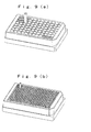
- the microtrubes are provided in a vertically oriented manner as shown in FIG. 9(a).
- ultramicrotubes in the same size storage rack they may be partitioned in a matrix with 16 columns and 24 rows to handle 384 ultramicrotubes as shown in FIG. 9(b).
- Patent Reference 1 which is Japanese Laid-Open Patent Publication No. 2000-4070 (page 11, lines 1 to 20, FIG. 6).
- Patent Reference 2 which is Japanese Patent No. 3421252 (page 2, paragraph 5, FIG. 1)
- the capacity of samples is also decreased so there must be a way to effectively utilize the space available. Further, since the dimensions of the grate of the storage rack are small, it is difficult to mold the storage rack.
- the storage rack frame has a dimensional accuracy less than a grate-shaped bottom portion of the storage rack which is formed inside the storage rack frame. Accordingly, a problem of lowered picking accuracy has been pointed out.
- the object of the present invention is to provide a pharmaceutical sample storage system in which the accommodation volume of a case for the sample is increased, the molding of the storage rack is easy, the case does not fall out even if the storage rack is turned upside down and the picking of the case from the storage rack is performed with high accuracy and efficiency.
- the invention provides a pharmaceutical sample storage system for cases in which samples are sealed therein and stored vertically in a storage rack accommodating a plurality of cases arranged in a matrix.
- the cases are rectangular in cross-section and hollow.
- the cases are tapered toward the bottom portion of the case and the corner portions of the outer surfaces of the cases are chamfered.
- the storage rack has a lower grate-shaped bottom portion partitioned inside a rack frame.
- the bottom portion of the case is fitted into one partitioned portion of the grate-shaped bottom portion.
- Supporting pins extend vertically upward from each intersection of gratings of the grated bottom portion.
- gratings it is meant the cross members which form the partitions.
- the chamfered corner portions of the cases in the present invention means a so-called C chamfering in which a right angular corner portion is corner-cut at an angle of 45°.
- a lower grate-shaped bottom portion means that it has substantially the same level of a side wall of the bottom portion of the case.
- the case in the present invention means a microtube or the like in which a sample for a wound medicine is sealed.
- the cases are available for use with other medicines and with other substances other than medicines.
- the case may be one of 384 cases which can be accommodated in a matrix with 16 columns and 24 rows.
- a conventional storage rack includes 96 cases arranged in a matrix with 8 columns and 12 rows.
- the invention in addition to the configuration already described further includes protrusions extending from inner side surfaces of the partitions which form the grate-shaped bottom portion.
- the partitions are formed by cross members which include inner side surfaces.
- the inner side surfaces are provided with case locking protrusions.
- a case locking concave portion is provided in each of the side walls of the bottom portion of the case. The case locking protrusions and case locking concave portions are fitted to each other when the case is inserted in the storage rack.
- the invention further includes case supporting pins which may be either circular or square in cross-section.
- the invention further includes supporting pins whose taper is thinner toward the tip portion.
- the invention further includes a molded grate-shaped bottom portion having a dimensional accuracy higher than the storage rack frame.
- the grate-shaped bottom portion includes first and second orienting protrusions which are located on orthogonal walls or perpendicular walls.
- the first and second orienting protrusions are orthogonal or perpendicular and are used in conjunction with actuators and fixing jigs to accurately position the storage rack relative to these highly accurate orienting protrusions.
- the orienting protrusions are sometimes referred to herein as positioning protrusions.
- the invention is a pharmaceutical sample storage system which includes a plurality of cases containing a plurality of samples which are sealed and vertically stored in a storage rack.
- the storage rack and the cases are arranged in a matrix.
- the cases are rectangularly shaped in cross-section and are hollow.
- the cases are tapered toward their bottom portions and are chamfered on the corner portions of the outer surfaces of the cases.
- the storage rack has a lower grate-shaped bottom portion partitioned in a grate manner inside the storage rack frame.
- the bottom portion of the case is fitted into one partition of the grated bottom portion.
- the grate-shaped bottom portion includes case supporting pins provided vertically upward from each of the intersection of gratings (sometimes herein the grating are referred to as cross members) of the grated bottom portion.
- High partitioning walls do not exist in the storage rack and the cross-section of the case area is increased as large as possible by chamfering the corners of the rectangularly-shaped in cross-section case. Thus the volume
- the invention includes partitions which form the grate-shaped bottom portion.
- the partitions are made up of cross members which form a grid or a grate.
- Each cross member includes an inner side surface thereof which includes case locking protrusions on each inner side of each cross member.
- Each case includes side walls and a bottom portion of the side walls include case locking concave portions therein which interengage the protrusions of the inner side surface of the cross members which form the partitions.
- the interengagement of the protrusions of the cross members of the partitions which form the grate-shaped bottom portion of the storage rack with the concavities in the bottom portions of the cases prevents the cases from falling out of the storage rack even when the storage rack is turned upside down. This results in saving the samples and keeping them in order as they are stored in the storage rack in order to facilitate further use of them.
- Case supporting pins which extend vertically from the bottom portion of the storage rack are circular or square in cross-section.
- the sample cases include chamfered corner portions so as to efficiently house four cases adjacent a particular case supporting pin.
- the volume or space available for the cases in a given storage rack is increased and more samples can be stored because more cases can be stored in the storage rack.
- Case supporting pins are tapered such that they are thinner toward the tip portion of the pin as they extend away from the bottom portion of the case. Tapered pins and cases having chamfered corners enable the easy insertion of the case into the storage rack.
- the grate-shaped bottom portion is molded to a dimensional accuracy or tolerance which is higher than the dimensional tolerance or accuracy of the storage rack frame.
- Positioning or orienting protrusions extend from two sides of the grate-shaped bottom portion. The two sides are perpendicular to each other and the positioning of the storage rack can be facilitated at high accuracy with respect to the dimensionally accurate grate-shaped bottom portion of the storage rack in spite of the fact that the outermost surface of the storage rack has poor dimensional accuracy.
- the dimensional accuracy of the grate-shaped bottom portion of the storage rack determines the ultimate positioning of the cases so that they may be removed or inserted into the rack.
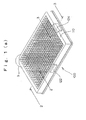
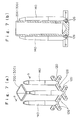
- FIG. 1(a) shows a perspective view of a storage rack for vertically accommodating a plurality of cases in which samples for pharmaceutical development are sealed.
- FIG. 1(b) shows an enlarged portion of FIG. 1(a).
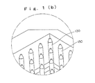
- FIG. 2 shows a cross-sectional view through line 2-2 of FIG. 1(a)
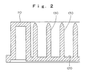
- FIG. 3 shows a cross-sectional view through line 3-3 of FIG. 1(a).
- a storage rack 100 in the present invention includes a lower grate-shaped bottom portion.
- the grate-shaped bottom portion includes partitions inside a rack frame 110 forming the outer frame of the storage rack 100 as shown in FIGS. 1 to 3.
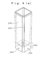
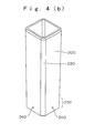
- Cases 200, 300 include bottom portions 230, 330.
- Bottom portion side walls 230, 330 of cases 200, 300 (shown in FIGS. 4 and 5) are respectively fitted into a partitioned portion of the grate-shaped bottom portion 120 as shown in FIGS. 6 and 7.
- case supporting pins 130, 140 are vertically provided and extend upwardly from the respective intersections of cross members of the grate-shaped bottom portions 120.
- the gratings or cross members form the partitions.
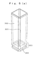
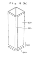
- FIGS. 4(a) and 5(a) broken lines illustrate the interior of the cases in perspective views.
- FIGS. 4(b) and 5(b) illustrate the cases in perspective views.
- Case supporting pins 130 are shown in FIGS. 6(a) and 6(b). Case supporting pins are circular in cross-section and are tapered thinner as they extend upwardly as viewed in FIGS. 6(a) and 6(b). Case supporting pins 140 shown in FIGS. 7(a) and 7(b) are square in cross-section and are tapered thinner as they extend upwardly. Cross-sectional views taken along the lines b-b of FIGS. 6(a) and 7(a) are shown in FIGS. 6(b) and 7(b) respectively.
- grate position (i.e., partition) numbers are provided on the top surfaces of case supporting pins 130, 140 and/or near the respective grate intersections of the grate-shaped bottom portions 120, an operator can easily identify the positions (i.e., partition) for inserting or removing a case from the position (partition) of interest.
- other cross-sectional shapes of the case supporting pins may be used and may constitute any polygonal cross-sectional shape including, for example, a star shape, a circular shape and a square shape.
- Cases 200, 300 in the present invention have rectangular cross-sectional shapes and are hollow as shown in FIGS. 4 and 5.
- the cases are tapered toward the bottom portions thereof. Additionally the corner portions of the outer surfaces of cases 200, 300 are chamfered at an angle of 45°, that is, they are subjected to so-called C chamfering.
- each case supporting pin 140 is vertically provided so that a side surface of the case supporting pin 140 abuts or is in proximity to a chamfered surface of the case 200 (300) as shown in FIG. 7(a)
- the chamfered surfaces are denoted by reference numerals 220, 320 in FIGS. 4 and 5.
- the inner side surfaces of cross members (gratings) forming the grate-shaped bottom portion 120 are provided with case locking protrusions 126 as shown in FIGS. 6(a), 6(b), 7(a) and 7(b).
- Side wall bottom portions 230, 330 of cases 200, 300 are respectively provided with case locking concave portions as shown in FIGS. 4(a), 4(b), 5(a) and 5(b).
- Case 200 in FIGS. 4(a) and 4(b) include circular recesses 240 as the case locking concave portions.
- the circular recesses are provided at an intermediate location which can be generally described as the center of each surface of the bottom portion side wall 230.
- Case 300 in FIGS. 5(a) and 5(b) illustrate a horizontal extending groove portion 340 as the case locking concave portion.
- the horizontally extending groove portion is provided at an intermediate location which can be generally described as the center of each surface of the bottom portion side wall 330.
- case locking protrusion portions 126 provided on the inner side surfaces of each side of the cross members of the grate-shaped bottom portions 120 are fitted into the circular recesses 240 of the case 200 or the horizontal groove portions 340 of the case 300, so that the case 200, 300 is prevented from falling out of the rack.
- structure for preventing a case or cases from falling out of a storage rack includes case locking concave portions provided on the cases themselves.
- the case locking concave portion coacts with protrusions on cross members of grate-shaped bottom portions of the storage rack.
- Case locking protrusions are provided on the inner side wall of cross members (gratings)of the case.
- case locking concave portions may be provided on upper portions of the case and the corresponding case locking protruded portions are provided on side surfaces of the case supporting pins, and the like may be considered.
- a storage rack is generally manufactured by resin molding and the outermost surface of the storage rack, that is a rack frame 110 in the present invention, has poor dimensional accuracy.
- the grate-shaped bottom portion 120 and the case supporting pins 130, 140 extending therefrom are important and are accurately molded by using another more accurate mold. Therefore, it is necessary to position the storage rack based on the grate-shaped bottom portions 120.
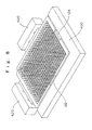
- the present invention has a structure that positions protruded portions 122, 124 extending from the grate-shaped bottom portion 120 on two surfaces of the grate-shaped bottom portion 120 perpendicular to each other in such a manner that the positioning protruded portions 122, 124 extend from the rack frame 110. See, Fig. 3 wherein protrusion 124 is illustrated as being formed with and molded with the grate-shaped bottom portion 120. As shown in FIG.
- a fixing jig 400 abuts the exposed positioning (orienting) protruded portions 122, 124 (positioning or orienting protrusions) and the remaining two surfaces of the grate-shaped bottom portion 120 are held by actuators 420 so that the positioning of the storage rack can be attained based on the accurate dimensions of the grate-shaped bottom portion 120 of the storage rack.
- the protrusions 122, 124 provide orthogonal reference surfaces to position the grate-shaped bottom portion 120 against the fixing jig 400 illustrated in Fig. 8, thus locating all of the highly accurate partitions in a highly accurate manner.
- positioning protruded portions 122, 124 have good dimensional accuracy enabling accurate positioning of the grate-shaped portions 120 as described and shown in Figs. 1-3.
- insertion holes may be provided on two side surfaces of the rack frame which are perpendicular and which are not dimensionally accurate. Orienting and protruding portions of fixing jigs are inserted into the insertion holes (openings) and the orienting protrusions are urged into engagement with a fixing jig positioning the grate-shaped bottom of the storage rack.
- the fixing jig includes protrusions which engage the dimensionally accurate grate-shaped bottom portion.
- the head portions of the cases are open and these cases are accommodated into a storage rack. Then when the cases are stored and transported an aluminum thin film sheet is adhered to an opening portion of each case by heating deposition. The thin aluminum film sheet is then cut to seal the case.
- the present invention accommodates 384 ultramicrotubes while using the same size storage rack which usually accommodates 96 conventional microtubes. Additionally, dead space occupied by partition walls is minimized or eliminated and the capacity of the tube case is increased. Thus, the present invention has significantly high industrial applicability in fields other than the field of pharmaceutical development.
Abstract
Description
- The present invention relates to a sample storage system for pharmaceutical development used for identifying and storing a number of samples. Samples may be used in the field of wound medicine research. The present invention relates to a sample storage system for pharmaceutical development wherein cases in which samples for pharmaceutical development are sealed and placed in a storage rack. The storage rack vertically stores a plurality of sample storage cases in a matrix.
- In the field of wound medicine research, for example, the storage and transportation of a storage rack has been carried out by sealing or encapsulating a sample-dissolved solution into a cylindrical case called a microtube. The storage rack accommodates a plurality of microtubes partitioned in a matrix, for example partitioned in a matrix with 8 columns and 12 rows for handling 96 microtubes. The microtrubes are provided in a vertically oriented manner as shown in FIG. 9(a). Further, to accommodate smaller microtubes, for instance, ultramicrotubes in the same size storage rack they may be partitioned in a matrix with 16 columns and 24 rows to handle 384 ultramicrotubes as shown in FIG. 9(b). See for example,
Patent Reference 1 which isJapanese Laid-Open Patent Publication No. 2000-4070 lines 1 to 20, FIG. 6). Also, seePatent Reference 2 which isJapanese Patent No. 3421252 page 2, paragraph 5, FIG. 1) - Since the above-mentioned conventional ultramicrotube has a shape in which the bottom surface size is reduced to substantially ¼ the size of a standard microtube, the capacity of samples is also decreased so there must be a way to effectively utilize the space available. Further, since the dimensions of the grate of the storage rack are small, it is difficult to mold the storage rack.
- Since the cases are inserted into a square partitioned portion of a grate in a storage rack, when the storage rack is turned upside down, the cases fall out. If this happens then there is an enormous loss of samples. Further, to reduce the cost of manufacturing the storage racks, the storage rack frame has a dimensional accuracy less than a grate-shaped bottom portion of the storage rack which is formed inside the storage rack frame. Accordingly, a problem of lowered picking accuracy has been pointed out.
- Accordingly, the object of the present invention is to provide a pharmaceutical sample storage system in which the accommodation volume of a case for the sample is increased, the molding of the storage rack is easy, the case does not fall out even if the storage rack is turned upside down and the picking of the case from the storage rack is performed with high accuracy and efficiency.
- The invention provides a pharmaceutical sample storage system for cases in which samples are sealed therein and stored vertically in a storage rack accommodating a plurality of cases arranged in a matrix. The cases are rectangular in cross-section and hollow. The cases are tapered toward the bottom portion of the case and the corner portions of the outer surfaces of the cases are chamfered. The storage rack has a lower grate-shaped bottom portion partitioned inside a rack frame. The bottom portion of the case is fitted into one partitioned portion of the grate-shaped bottom portion. Supporting pins extend vertically upward from each intersection of gratings of the grated bottom portion. By gratings it is meant the cross members which form the partitions.
- It is noted that the chamfered corner portions of the cases in the present invention means a so-called C chamfering in which a right angular corner portion is corner-cut at an angle of 45°. And a lower grate-shaped bottom portion means that it has substantially the same level of a side wall of the bottom portion of the case. Further, the case in the present invention means a microtube or the like in which a sample for a wound medicine is sealed. The cases are available for use with other medicines and with other substances other than medicines. The case may be one of 384 cases which can be accommodated in a matrix with 16 columns and 24 rows. A conventional storage rack includes 96 cases arranged in a matrix with 8 columns and 12 rows.
- The invention in addition to the configuration already described further includes protrusions extending from inner side surfaces of the partitions which form the grate-shaped bottom portion. The partitions are formed by cross members which include inner side surfaces. The inner side surfaces are provided with case locking protrusions. A case locking concave portion is provided in each of the side walls of the bottom portion of the case. The case locking protrusions and case locking concave portions are fitted to each other when the case is inserted in the storage rack.
- The invention further includes case supporting pins which may be either circular or square in cross-section. The invention further includes supporting pins whose taper is thinner toward the tip portion.
- The invention further includes a molded grate-shaped bottom portion having a dimensional accuracy higher than the storage rack frame. The grate-shaped bottom portion includes first and second orienting protrusions which are located on orthogonal walls or perpendicular walls. The first and second orienting protrusions are orthogonal or perpendicular and are used in conjunction with actuators and fixing jigs to accurately position the storage rack relative to these highly accurate orienting protrusions. The orienting protrusions are sometimes referred to herein as positioning protrusions.
- The invention is a pharmaceutical sample storage system which includes a plurality of cases containing a plurality of samples which are sealed and vertically stored in a storage rack. The storage rack and the cases are arranged in a matrix. The cases are rectangularly shaped in cross-section and are hollow. The cases are tapered toward their bottom portions and are chamfered on the corner portions of the outer surfaces of the cases. The storage rack has a lower grate-shaped bottom portion partitioned in a grate manner inside the storage rack frame. The bottom portion of the case is fitted into one partition of the grated bottom portion. The grate-shaped bottom portion includes case supporting pins provided vertically upward from each of the intersection of gratings (sometimes herein the grating are referred to as cross members) of the grated bottom portion. High partitioning walls do not exist in the storage rack and the cross-section of the case area is increased as large as possible by chamfering the corners of the rectangularly-shaped in cross-section case. Thus the volume of sample per case can be increased.
- The invention includes partitions which form the grate-shaped bottom portion. The partitions are made up of cross members which form a grid or a grate. Each cross member includes an inner side surface thereof which includes case locking protrusions on each inner side of each cross member. Each case includes side walls and a bottom portion of the side walls include case locking concave portions therein which interengage the protrusions of the inner side surface of the cross members which form the partitions. The interengagement of the protrusions of the cross members of the partitions which form the grate-shaped bottom portion of the storage rack with the concavities in the bottom portions of the cases prevents the cases from falling out of the storage rack even when the storage rack is turned upside down. This results in saving the samples and keeping them in order as they are stored in the storage rack in order to facilitate further use of them.
- Case supporting pins which extend vertically from the bottom portion of the storage rack are circular or square in cross-section. The sample cases include chamfered corner portions so as to efficiently house four cases adjacent a particular case supporting pin. Thus, the volume or space available for the cases in a given storage rack is increased and more samples can be stored because more cases can be stored in the storage rack.
- Case supporting pins are tapered such that they are thinner toward the tip portion of the pin as they extend away from the bottom portion of the case. Tapered pins and cases having chamfered corners enable the easy insertion of the case into the storage rack.
- The grate-shaped bottom portion is molded to a dimensional accuracy or tolerance which is higher than the dimensional tolerance or accuracy of the storage rack frame. Positioning or orienting protrusions extend from two sides of the grate-shaped bottom portion. The two sides are perpendicular to each other and the positioning of the storage rack can be facilitated at high accuracy with respect to the dimensionally accurate grate-shaped bottom portion of the storage rack in spite of the fact that the outermost surface of the storage rack has poor dimensional accuracy. The dimensional accuracy of the grate-shaped bottom portion of the storage rack determines the ultimate positioning of the cases so that they may be removed or inserted into the rack.
- FIGS. 1(a) and 1(b)
- are perspective views of a storage rack in a pharmaceutical sample storage system according to the present invention.
- FIG. 2
- is a cross-sectional view of the storage rack through the line 2-2 shown in FIG. 1.
- FIG. 3
- is a cross-sectional view of the storage rack through the line 3-3 shown in FIG. 1.
- FIGS. 4(a) and 4(b)
- are perspective views of a case having a locking circular recess used in the present invention.
- FIG. 5
- is a perspective view of a case having a locking horizontal groove portion used in the present invention.
- FIGS. 6(a) and 6(b)
- are perspective views showing case supporting structure including case supporting pins each having a circular cross-section.
- FIG.S 7(a) and 7(b)
- are perspective views showing case supporting structure including case supporting pins each having a square cross-section.
- FIG. 8
- is a perspective view showing a storage rack positioning structure according to the present invention.
- FIG. 9
- is a perspective view showing a conventional microtube and a storage rack.
- The drawings will be better understood when reference is made to the Description Of The Invention and Claims which follow hereinbelow.
- Next a pharmaceutical sample storage system according to the present invention will be described with reference to drawings. FIG. 1(a) shows a perspective view of a storage rack for vertically accommodating a plurality of cases in which samples for pharmaceutical development are sealed. FIG. 1(b) shows an enlarged portion of FIG. 1(a). FIG. 2 shows a cross-sectional view through line 2-2 of FIG. 1(a), and FIG. 3 shows a cross-sectional view through line 3-3 of FIG. 1(a).
- A
storage rack 100 in the present invention includes a lower grate-shaped bottom portion. The grate-shaped bottom portion includes partitions inside arack frame 110 forming the outer frame of thestorage rack 100 as shown in FIGS. 1 to 3.Cases bottom portions portion side walls cases 200, 300 (shown in FIGS. 4 and 5) are respectively fitted into a partitioned portion of the grate-shapedbottom portion 120 as shown in FIGS. 6 and 7. Further,case supporting pins bottom portions 120. The gratings or cross members form the partitions. - It is noted that in FIGS. 4(a) and 5(a) broken lines illustrate the interior of the cases in perspective views. FIGS. 4(b) and 5(b) illustrate the cases in perspective views.
-
Case supporting pins 130 are shown in FIGS. 6(a) and 6(b). Case supporting pins are circular in cross-section and are tapered thinner as they extend upwardly as viewed in FIGS. 6(a) and 6(b).Case supporting pins 140 shown in FIGS. 7(a) and 7(b) are square in cross-section and are tapered thinner as they extend upwardly. Cross-sectional views taken along the lines b-b of FIGS. 6(a) and 7(a) are shown in FIGS. 6(b) and 7(b) respectively. - It is noted that when the grate position (i.e., partition) numbers are provided on the top surfaces of
case supporting pins bottom portions 120, an operator can easily identify the positions (i.e., partition) for inserting or removing a case from the position (partition) of interest. Further, other cross-sectional shapes of the case supporting pins may be used and may constitute any polygonal cross-sectional shape including, for example, a star shape, a circular shape and a square shape. -
Cases cases case supporting pin 140, eachcase supporting pin 140 is vertically provided so that a side surface of thecase supporting pin 140 abuts or is in proximity to a chamfered surface of the case 200 (300) as shown in FIG. 7(a) The chamfered surfaces are denoted byreference numerals - The inner side surfaces of cross members (gratings) forming the grate-shaped
bottom portion 120 are provided withcase locking protrusions 126 as shown in FIGS. 6(a), 6(b), 7(a) and 7(b). Side wallbottom portions cases -
Case 200 in FIGS. 4(a) and 4(b) includecircular recesses 240 as the case locking concave portions. The circular recesses are provided at an intermediate location which can be generally described as the center of each surface of the bottomportion side wall 230. -
Case 300 in FIGS. 5(a) and 5(b) illustrate a horizontal extendinggroove portion 340 as the case locking concave portion. The horizontally extending groove portion is provided at an intermediate location which can be generally described as the center of each surface of the bottomportion side wall 330. - And as shown in FIGS. 6(a), 6(b), 7(a) and 7(b) when
cases protrusion portions 126 provided on the inner side surfaces of each side of the cross members of the grate-shapedbottom portions 120 are fitted into thecircular recesses 240 of thecase 200 or thehorizontal groove portions 340 of thecase 300, so that thecase - It is noted that structure for preventing a case or cases from falling out of a storage rack includes case locking concave portions provided on the cases themselves. The case locking concave portion coacts with protrusions on cross members of grate-shaped bottom portions of the storage rack. Case locking protrusions are provided on the inner side wall of cross members (gratings)of the case.
- Also, case locking concave portions may be provided on upper portions of the case and the corresponding case locking protruded portions are provided on side surfaces of the case supporting pins, and the like may be considered.
- Next, a storage rack positioning method in a pharmaceutical sample storage system according to the present invention will be described. A storage rack is generally manufactured by resin molding and the outermost surface of the storage rack, that is a
rack frame 110 in the present invention, has poor dimensional accuracy. The grate-shapedbottom portion 120 and thecase supporting pins bottom portions 120. - Thus as shown in FIGS. 1(a), 1(b) and 3 the present invention has a structure that positions protruded
portions bottom portion 120 on two surfaces of the grate-shapedbottom portion 120 perpendicular to each other in such a manner that the positioning protrudedportions rack frame 110. See, Fig. 3 whereinprotrusion 124 is illustrated as being formed with and molded with the grate-shapedbottom portion 120. As shown in FIG. 8 a fixingjig 400 abuts the exposed positioning (orienting) protrudedportions 122, 124 (positioning or orienting protrusions) and the remaining two surfaces of the grate-shapedbottom portion 120 are held byactuators 420 so that the positioning of the storage rack can be attained based on the accurate dimensions of the grate-shapedbottom portion 120 of the storage rack. Theprotrusions bottom portion 120 against the fixingjig 400 illustrated in Fig. 8, thus locating all of the highly accurate partitions in a highly accurate manner. - It is noted that in the present invention positioning protruded
portions portions 120 as described and shown in Figs. 1-3. - Alternatively in an embodiment not shown in the drawings, insertion holes (openings) may be provided on two side surfaces of the rack frame which are perpendicular and which are not dimensionally accurate. Orienting and protruding portions of fixing jigs are inserted into the insertion holes (openings) and the orienting protrusions are urged into engagement with a fixing jig positioning the grate-shaped bottom of the storage rack. Essentially, in this embodiment the fixing jig includes protrusions which engage the dimensionally accurate grate-shaped bottom portion.
- In the present invention the head portions of the cases are open and these cases are accommodated into a storage rack. Then when the cases are stored and transported an aluminum thin film sheet is adhered to an opening portion of each case by heating deposition. The thin aluminum film sheet is then cut to seal the case.
- The present invention accommodates 384 ultramicrotubes while using the same size storage rack which usually accommodates 96 conventional microtubes. Additionally, dead space occupied by partition walls is minimized or eliminated and the capacity of the tube case is increased. Thus, the present invention has significantly high industrial applicability in fields other than the field of pharmaceutical development.
-
- 100
- Storage rack
- 110
- Rack frame
- 120
- Grate-shaped bottom portion
- 122, 124
- Positioning protruded portion
- 126
- Case locking protruded portion
- 130, 140
- Case supporting pin
- 200, 300
- Case
- 220, 320
- Chamfered surface
- 230, 330
- Bottom portion side wall
- 240
- Case locking concave portion (circular recess)
- 340
- Case locking concave portion (horizontal groove portion)
- 400
- Fixing jig
- 420
- Actuator
Claims (8)
- Pharmaceutical sample storage system comprising cases (200, 300) in which samples for pharmaceutical development are sealed, a storage rack frame (110) for storing a plurality of said cases (200, 300) in a matrix, characterized in that
each of said cases (200, 300) is hollow and rectangularly-shaped in cross-section, each of said cases (200, 300) includes a bottom portion, each of said cases (200, 300) is tapered toward said bottom portion of said case (200, 300), each of said cases (200, 300) includes outer corner portions which are chamfered, and,
said storage rack (100) has a lower grate-shaped bottom portion (120), said grate-shaped bottom portion (120) formed into partitions, said grate-shaped bottom portion (120) includes case supporting pins extending upwardly therefrom, said bottom portions of each of said cases (200, 300) being fitted into a respective partition of said grate-shaped bottom portion (120) and between said upwardly extending case supporting pins (130, 140). - Pharmaceutical sample storage system according to claim 1, characterized in that each of said partitions of said grate-shaped bottom portion (120) includes protrusions (126), each of said cases (200, 300) includes corresponding locking concave portions (240), and said protrusions (126) of each said partition interengaging said corresponding locking concave portions (240) of each of said cases (200, 300) securing said cases (200, 300).
- Pharmaceutical sample storage system according to claim 1 or 2, characterized in that said case supporting pins (130) are circular in cross-section.
- Pharmaceutical sample storage system according to any of claims 1 to 3, characterized in that said case supporting pins (140) are square in cross-section.
- Pharmaceutical sample storage system according to any of claims 1 to 4, characterized in that said case supporting pins (130, 140) include a tip portion and said case supporting pins (130, 140) are tapered thinner toward the tip portion.
- Pharmaceutical sample storage system according to any of claims 1 to 5, characterized in that said grate-shaped bottom portion (120) is molded with a higher degree of accuracy than said storage rack frame (110), a first and a second storage rack positioning protrusion (122, 124) extending from first and second perpendicular sides of said grate-shaped bottom portion (120), and, an actuator (420) interengaging said first and second positioning protrusions (122, 124) extending from said first and second perpendicular side of said grate-shaped bottom portion (120) positioning said storage rack frame (110) such that said cases (200, 300) may be easily and accurately removed from and inserted into said storage rack frame (110).
- Pharmaceutical sample storage system according to any of claims 1 to 6, characterized in that insertion holes are provided on two side surfaces of the rack frame which are perpendicular and which are not dimensionally accurate, and that orienting and protruding portions of fixing jigs are inserted into the insertion holes, and the orienting protrusions are urged into engagement with a fixing jig positioning the grate-shaped bottom of the storage rack.
- Pharmaceutical sample storage system according to any of claim 7, characterized in that the fixing jig includes protrusions which engage the dimensionally accurate grate-shaped bottom portion.
Applications Claiming Priority (1)
| Application Number | Priority Date | Filing Date | Title |
|---|---|---|---|
| JP2005212690A JP4473189B2 (en) | 2005-07-22 | 2005-07-22 | Drug storage system for drug discovery |
Publications (3)
| Publication Number | Publication Date |
|---|---|
| EP1745850A2 true EP1745850A2 (en) | 2007-01-24 |
| EP1745850A3 EP1745850A3 (en) | 2007-11-14 |
| EP1745850B1 EP1745850B1 (en) | 2011-01-19 |
Family
ID=37402523
Family Applications (1)
| Application Number | Title | Priority Date | Filing Date |
|---|---|---|---|
| EP06013680A Active EP1745850B1 (en) | 2005-07-22 | 2006-07-01 | Sample storage system for pharmaceutical development |
Country Status (4)
| Country | Link |
|---|---|
| US (1) | US7892504B2 (en) |
| EP (1) | EP1745850B1 (en) |
| JP (1) | JP4473189B2 (en) |
| DE (1) | DE602006019667D1 (en) |
Cited By (4)
| Publication number | Priority date | Publication date | Assignee | Title |
|---|---|---|---|---|
| EP1852187A1 (en) * | 2006-05-01 | 2007-11-07 | Tsubakimoto Chain Co. | Samples storage system for pharmaceutical development |
| EP1985368A1 (en) * | 2007-04-24 | 2008-10-29 | Tsubakimoto Chain Co. | Microtube picking device for pharmaceutical development |
| US7892504B2 (en) | 2005-07-22 | 2011-02-22 | Tsubakimoto Chain Co. | Pharmaceutical sample storage system |
| EP3848124A4 (en) * | 2018-09-08 | 2022-06-01 | Biodyne Co., Ltd. | Vial device for storing and smearing exfoliative cell |
Families Citing this family (28)
| Publication number | Priority date | Publication date | Assignee | Title |
|---|---|---|---|---|
| US8381919B2 (en) * | 2005-11-16 | 2013-02-26 | Electrolux Home Products Corporation N.V. | Storing device for a dishwashing machine |
| JP2008267831A (en) * | 2007-04-16 | 2008-11-06 | Tsubakimoto Chain Co | Displacement control method of hand mechanism for drug design |
| JP4827787B2 (en) * | 2007-04-17 | 2011-11-30 | 株式会社椿本チエイン | Method for determining presence or absence of solution in drug discovery container |
| JP4884302B2 (en) * | 2007-05-29 | 2012-02-29 | 株式会社椿本チエイン | Drug discovery tube storage system |
| JP4916975B2 (en) * | 2007-08-08 | 2012-04-18 | 株式会社椿本チエイン | Drug discovery tube storage system |
| JP4616363B2 (en) | 2008-03-05 | 2011-01-19 | 株式会社椿本チエイン | Microtube cap for drug discovery |
| JP5020138B2 (en) * | 2008-03-19 | 2012-09-05 | 株式会社椿本チエイン | Drug discovery microtube cap mounting device |
| EP3459635B1 (en) | 2008-04-11 | 2021-03-03 | Biotix, Inc. | Pipette tip handling devices |
| US8136679B2 (en) | 2009-02-03 | 2012-03-20 | Genesee Scientific Corporation | Tube reload system and components |
| US8590736B2 (en) * | 2009-04-11 | 2013-11-26 | Biotix, Inc. | Automated pipette tip loading devices and methods |
| USD697227S1 (en) * | 2009-04-11 | 2014-01-07 | Biotix, Inc. | Pipette tip handling device set |
| JP5289287B2 (en) * | 2009-11-27 | 2013-09-11 | 株式会社椿本チエイン | Work stocker |
| JP4926235B2 (en) * | 2009-12-25 | 2012-05-09 | 株式会社椿本チエイン | Drug container transfer device |
| GB201018624D0 (en) * | 2010-11-04 | 2010-12-22 | Epistem Ltd | Reaction vessel |
| GB201120626D0 (en) * | 2011-11-30 | 2012-01-11 | Ge Healthcare Uk Ltd | Biological sample storage apparatus and method |
| US20140158645A1 (en) * | 2012-08-03 | 2014-06-12 | Thomas Concepts, LLC | System and Method Related to a Storage and Retrieval Device for Clasping Mechanisms |
| WO2014069244A1 (en) * | 2012-10-31 | 2014-05-08 | 株式会社大協精工 | Container-holding toilet |
| US9619799B2 (en) * | 2013-02-06 | 2017-04-11 | Apple Inc. | Apparatus and methods for secure element transactions and management of assets |
| GB201319759D0 (en) * | 2013-11-08 | 2013-12-25 | Thomsen Lars | Device and method for heating a fluid chamber |
| JP6324341B2 (en) * | 2015-03-27 | 2018-05-16 | 株式会社椿本チエイン | Cold storage container and positioning flange |
| JP5939720B1 (en) * | 2015-03-31 | 2016-06-22 | 株式会社椿本チエイン | Rack positioning device |
| US20170087480A1 (en) * | 2015-06-02 | 2017-03-30 | Moose Creative Management Pty Limited | Adhesive toy beads |
| US10898821B2 (en) | 2015-06-02 | 2021-01-26 | Moose Creative Management Pty Limited | Adhesive toy beads |
| EP3196656B1 (en) * | 2016-01-20 | 2021-07-14 | Brooks Automation, Inc. | Automated sample storage system having storage consumable with sub-optimal storage density |
| DE102016113925A1 (en) * | 2016-07-28 | 2018-02-01 | Infineon Technologies Ag | Wafer box, wafer stacking aid, wafer carrier, wafer transport system, wafer wafer loading method and wafer wafer removal method |
| JP7057209B2 (en) * | 2018-05-11 | 2022-04-19 | 株式会社ダーツライブ | Shuriken target |
| CN112623514B (en) * | 2020-12-29 | 2022-07-19 | 台州市立医院 | Rotation type medicine light-resistant storage device |
| CN114146745A (en) * | 2021-11-14 | 2022-03-08 | 广州源古纪科技有限公司 | Clinical laboratory's alveolar lavage liquid sample preservation equipment |
Citations (2)
| Publication number | Priority date | Publication date | Assignee | Title |
|---|---|---|---|---|
| JP3421252B2 (en) | 1997-09-29 | 2003-06-30 | エフ.ホフマン−ラ ロシュ アーゲー | Compound handling system |
| EP1477226A1 (en) | 2003-05-13 | 2004-11-17 | The Automation Partnership (Cambridge) Limited | Test tube for storing fluid |
Family Cites Families (76)
| Publication number | Priority date | Publication date | Assignee | Title |
|---|---|---|---|---|
| US263116A (en) * | 1882-08-22 | Case for bottles | ||
| US353600A (en) * | 1886-11-30 | Bottle | ||
| US840558A (en) * | 1905-09-29 | 1907-01-08 | John W Denmead | Egg-carrier. |
| US955164A (en) * | 1909-11-29 | 1910-04-19 | Ellsworth E Husted | Plant-carrier. |
| US1022971A (en) * | 1911-05-16 | 1912-04-09 | George G Roberts | Bottle-case. |
| US1236085A (en) * | 1916-01-03 | 1917-08-07 | Richard Hudnut | Bottle-display stand. |
| US1681110A (en) * | 1927-08-12 | 1928-08-14 | Friedman William | Cooling vending container for drinks |
| US1869717A (en) * | 1930-02-12 | 1932-08-02 | Henry B Silver | Bottle holder |
| US2467873A (en) * | 1945-09-29 | 1949-04-19 | Weir Hugo | Telltale signal for counter displays |
| US2636615A (en) * | 1952-04-02 | 1953-04-28 | Clifton R Bradley | Article holder, including coacting gripping fingers |
| GB758517A (en) | 1953-03-21 | 1956-10-03 | Eric Clifford Turner | Improved bottle container |
| US2878920A (en) * | 1955-04-11 | 1959-03-24 | Cherry Burrell Corp | Universal bottle pocket |
| US3176504A (en) * | 1962-05-21 | 1965-04-06 | Justin J Shapiro | Rack for hematocrit tubes |
| US3327885A (en) * | 1964-10-06 | 1967-06-27 | Phillips Petroleum Co | Bottle carrier |
| US3381825A (en) * | 1966-07-22 | 1968-05-07 | Packaging Corp America | Tray construction |
| US3463323A (en) * | 1967-04-14 | 1969-08-26 | Rapidograph Inc | Stand for tube writing pens |
| US3643812A (en) * | 1970-06-12 | 1972-02-22 | Owens Illinois Inc | Tube storage rack |
| DE2113499A1 (en) * | 1971-03-19 | 1972-09-21 | Guenter Noethen | Flower pot grid |
| US3889416A (en) * | 1973-12-10 | 1975-06-17 | Duncan G Bergeron | Seedling tree growing apparatus |
| USRE34133E (en) * | 1976-07-23 | 1992-11-24 | Dynatech Holdings, Ltd. | Microtest plates |
| US4154795A (en) * | 1976-07-23 | 1979-05-15 | Dynatech Holdings Limited | Microtest plates |
| US4159597A (en) * | 1977-02-28 | 1979-07-03 | Illinois Tool Works Inc. | Planting system including articles of manufacture |
| US4168955A (en) * | 1977-03-28 | 1979-09-25 | Instrumentation Specialties Company | Chemical analyzer |
| US4956150A (en) * | 1985-11-27 | 1990-09-11 | Alerchek | Disposable microtiter stick |
| US5084246A (en) * | 1986-10-28 | 1992-01-28 | Costar Corporation | Multi-well test plate |
| US4948564A (en) | 1986-10-28 | 1990-08-14 | Costar Corporation | Multi-well filter strip and composite assemblies |
| US4798292A (en) * | 1987-04-03 | 1989-01-17 | Biomedical Laser Industries | Sterilization, storage, and presentation container for surgical instruments |
| US5201430A (en) * | 1989-05-23 | 1993-04-13 | Advent Medico, Inc. | Instrument holder |
| FI87278C (en) * | 1989-08-28 | 1992-12-10 | Labsystems Oy | Cuvette matrix and position for this |
| US5248035A (en) * | 1990-09-06 | 1993-09-28 | Patrick Gallagher | Collection and storage unit for recyclable containers |
| KR100236506B1 (en) * | 1990-11-29 | 2000-01-15 | 퍼킨-엘머시터스인스트루먼츠 | Apparatus for polymerase chain reaction |
| US5098676B2 (en) * | 1991-01-04 | 1997-11-25 | Poly Vac Inc | Sterilization and storage container tray |
| DE4103146C1 (en) * | 1991-02-02 | 1992-03-26 | Richard Wolf Gmbh, 7134 Knittlingen, De | |
| US5112574A (en) * | 1991-04-26 | 1992-05-12 | Imanigation, Ltd. | Multititer stopper array for multititer plate or tray |
| JPH05157684A (en) * | 1991-12-02 | 1993-06-25 | Seikagaku Kogyo Co Ltd | Absorptionmeter |
| US5279800A (en) * | 1992-11-25 | 1994-01-18 | C/T Med-Systems Ltd., Inc. | Dental cassette kit |
| US5366893A (en) * | 1993-01-13 | 1994-11-22 | Becton, Dickinson And Company | Culture vessel |
| US5379900A (en) * | 1993-08-03 | 1995-01-10 | Becton, Dickinson And Company | Needle shielding cushion kit |
| US5407648A (en) * | 1993-09-29 | 1995-04-18 | Paragon Group Of Plastics Companies, Inc. | Combination sterilization tray and mat |
| CH687592A5 (en) * | 1993-10-18 | 1997-01-15 | Eidgenoess Munitionsfab Thun | Mehrgefaessanordnung for instrumental analysis. |
| US5514343A (en) * | 1994-06-22 | 1996-05-07 | Nunc, As | Microtitration system |
| US5525304A (en) * | 1994-06-24 | 1996-06-11 | Pasteur Sanofi Diagnostics | Apparatus for automated chemical analysis with variable reagents |
| US5792426A (en) * | 1994-10-11 | 1998-08-11 | Schweizerische Eidgenossenschaft Vertreten Durch Das Ac-Laboratorium Spiez Der Gruppe Rustung | Multi-well titerplate for instrumental analysis |
| US5759494A (en) * | 1995-10-05 | 1998-06-02 | Corning Incorporated | Microplates which prevent optical cross-talk between wells |
| US5858309A (en) * | 1996-03-22 | 1999-01-12 | Corning Incorporated | Microplates with UV permeable bottom wells |
| US5823363A (en) * | 1996-10-18 | 1998-10-20 | Cassel; Douglas | Medical syringe holding/transport apparatus |
| DE19704732A1 (en) * | 1997-02-07 | 1998-08-13 | Stratec Elektronik Gmbh | Luminescence measurement device |
| DE19712484C2 (en) * | 1997-03-25 | 1999-07-08 | Greiner Gmbh | Microplate with transparent bottom and process for its production |
| US5766561A (en) * | 1997-04-23 | 1998-06-16 | Case Medical, Inc. | Sterilizable silicone mat apparatus |
| US6297018B1 (en) * | 1998-04-17 | 2001-10-02 | Ljl Biosystems, Inc. | Methods and apparatus for detecting nucleic acid polymorphisms |
| US6838051B2 (en) * | 1999-05-03 | 2005-01-04 | Ljl Biosystems, Inc. | Integrated sample-processing system |
| US5962250A (en) * | 1997-10-28 | 1999-10-05 | Glaxo Group Limited | Split multi-well plate and methods |
| DE19806681B4 (en) * | 1998-02-18 | 2006-07-27 | Carl Zeiss Jena Gmbh | microtiter plate |
| US5950832A (en) * | 1998-06-03 | 1999-09-14 | Brandeis University | Elastomeric sheet and support member for storing specimen vials |
| USD420743S (en) * | 1998-06-24 | 2000-02-15 | Advanced Biotechnologies Limited | Multi-well plate |
| US6048504A (en) * | 1998-09-01 | 2000-04-11 | Riley Medical, Inc. | Pin mat for sterilization trays |
| US6193064B1 (en) * | 1998-11-04 | 2001-02-27 | J. G. Finneran Associates, Inc. | Multi-tier vial plate |
| US6875405B1 (en) * | 1999-02-01 | 2005-04-05 | Matrix Technologies Corporation | Tube rack |
| US6685034B1 (en) * | 1999-03-15 | 2004-02-03 | Michael Charles Cooke | Device for retaining articles |
| US6340589B1 (en) * | 1999-07-23 | 2002-01-22 | Mj Research, Inc. | Thin-well microplate and methods of making same |
| NL1012996C2 (en) * | 1999-09-08 | 2001-03-12 | Micronic B V | Sealing mat for sealing test tubes. |
| US20020108917A1 (en) * | 2001-01-15 | 2002-08-15 | Shoji Maruyama | Tube rack and clamp system |
| US6669911B1 (en) * | 2001-01-31 | 2003-12-30 | David W. Swanson | Frame for multiwell tray |
| GB0110449D0 (en) * | 2001-04-28 | 2001-06-20 | Genevac Ltd | Improvements in and relating to the heating of microtitre well plates in centrifugal evaporators |
| DE60215377T2 (en) * | 2001-06-14 | 2007-08-23 | Millipore Corp., Billerica | The multiwell cell growth apparatus |
| EP1361440A1 (en) | 2002-05-10 | 2003-11-12 | F. Hoffman-la Roche AG | Method and apparatus for transporting a plurality of test tubes in a measuring system |
| US7128878B2 (en) * | 2002-10-04 | 2006-10-31 | Becton, Dickinson And Company | Multiwell plate |
| FI20031773A0 (en) * | 2003-12-04 | 2003-12-04 | Thermo Electron Oy | The container platform |
| JP4328636B2 (en) | 2004-01-30 | 2009-09-09 | 株式会社カナック企画 | In-vehicle adapter and in-vehicle system using the same |
| JP4056982B2 (en) * | 2004-03-17 | 2008-03-05 | 株式会社アイディエス | Test tube holder |
| USD534658S1 (en) * | 2004-05-26 | 2007-01-02 | The Automation Partnership (Cambridge) Limited | Culture vessel block |
| US7458474B2 (en) * | 2005-02-24 | 2008-12-02 | Conrad Wayne Bewsky | Bulbous pin implement holder and tip protector for various sized implements |
| JP4749222B2 (en) * | 2006-05-01 | 2011-08-17 | 株式会社椿本チエイン | Drug storage system for drug discovery |
| JP4473189B2 (en) | 2005-07-22 | 2010-06-02 | 株式会社椿本チエイン | Drug storage system for drug discovery |
| US7669721B2 (en) * | 2005-12-01 | 2010-03-02 | Handi-Craft Company | Drying rack assembly for baby bottles |
| WO2007067759A2 (en) * | 2005-12-08 | 2007-06-14 | Protein Discovery, Inc. | Methods and devices for concentration and fractionation of analytes for chemical analysis |
-
2005
- 2005-07-22 JP JP2005212690A patent/JP4473189B2/en active Active
-
2006
- 2006-06-22 US US11/473,294 patent/US7892504B2/en active Active
- 2006-07-01 EP EP06013680A patent/EP1745850B1/en active Active
- 2006-07-01 DE DE602006019667T patent/DE602006019667D1/en active Active
Patent Citations (2)
| Publication number | Priority date | Publication date | Assignee | Title |
|---|---|---|---|---|
| JP3421252B2 (en) | 1997-09-29 | 2003-06-30 | エフ.ホフマン−ラ ロシュ アーゲー | Compound handling system |
| EP1477226A1 (en) | 2003-05-13 | 2004-11-17 | The Automation Partnership (Cambridge) Limited | Test tube for storing fluid |
Cited By (5)
| Publication number | Priority date | Publication date | Assignee | Title |
|---|---|---|---|---|
| US7892504B2 (en) | 2005-07-22 | 2011-02-22 | Tsubakimoto Chain Co. | Pharmaceutical sample storage system |
| EP1852187A1 (en) * | 2006-05-01 | 2007-11-07 | Tsubakimoto Chain Co. | Samples storage system for pharmaceutical development |
| EP1985368A1 (en) * | 2007-04-24 | 2008-10-29 | Tsubakimoto Chain Co. | Microtube picking device for pharmaceutical development |
| US7867455B2 (en) | 2007-04-24 | 2011-01-11 | T{grave over (s)}ubakimoto Chain Co. | Microtube picking device for pharmaceutical development |
| EP3848124A4 (en) * | 2018-09-08 | 2022-06-01 | Biodyne Co., Ltd. | Vial device for storing and smearing exfoliative cell |
Also Published As
| Publication number | Publication date |
|---|---|
| DE602006019667D1 (en) | 2011-03-03 |
| JP2007033061A (en) | 2007-02-08 |
| US20070017885A1 (en) | 2007-01-25 |
| EP1745850A3 (en) | 2007-11-14 |
| JP4473189B2 (en) | 2010-06-02 |
| US7892504B2 (en) | 2011-02-22 |
| EP1745850B1 (en) | 2011-01-19 |
Similar Documents
| Publication | Publication Date | Title |
|---|---|---|
| EP1745850B1 (en) | Sample storage system for pharmaceutical development | |
| US9297728B2 (en) | Storage unit and transfer system for biological samples | |
| ES2689528T3 (en) | Sample handling system | |
| US20070116613A1 (en) | Sample tube and system for storing and providing nucleic acid samples | |
| US8349279B2 (en) | Samples storage system for pharmaceutical development | |
| US20170348476A1 (en) | Covers for drug container piston arrays or piston nests and packages for cover and piston nest assemblies | |
| JP4975359B2 (en) | Method of sealing and separating multiple tubes enclosing a drug discovery sample | |
| EP2098295B1 (en) | Cap for microtube for pharmaceutical development | |
| US20170246630A1 (en) | Enhanced environmental control reservoir apparatus and method of use | |
| EP1852187B1 (en) | Samples storage system for pharmaceutical development | |
| JP3208610U (en) | Culture vessel | |
| WO2009094495A1 (en) | Tape adaptor | |
| JP2008275476A (en) | Storage rack for sample container, sample container, and sample storing set | |
| EP1752220A1 (en) | Sample tube | |
| JP4689528B2 (en) | Drug storage system for drug discovery | |
| JP2005083787A (en) | Cassette for medical examination | |
| JP2005091257A (en) | Cassette for medical examination | |
| CN112154329A (en) | Sample tube rack and sample tube rack assembly | |
| JP2005098780A (en) | Cassette for medical examination |
Legal Events
| Date | Code | Title | Description |
|---|---|---|---|
| PUAI | Public reference made under article 153(3) epc to a published international application that has entered the european phase |
Free format text: ORIGINAL CODE: 0009012 |
|
| AK | Designated contracting states |
Kind code of ref document: A2 Designated state(s): AT BE BG CH CY CZ DE DK EE ES FI FR GB GR HU IE IS IT LI LT LU LV MC NL PL PT RO SE SI SK TR |
|
| AX | Request for extension of the european patent |
Extension state: AL BA HR MK YU |
|
| PUAL | Search report despatched |
Free format text: ORIGINAL CODE: 0009013 |
|
| AK | Designated contracting states |
Kind code of ref document: A3 Designated state(s): AT BE BG CH CY CZ DE DK EE ES FI FR GB GR HU IE IS IT LI LT LU LV MC NL PL PT RO SE SI SK TR |
|
| AX | Request for extension of the european patent |
Extension state: AL BA HR MK YU |
|
| 17P | Request for examination filed |
Effective date: 20071129 |
|
| RIN1 | Information on inventor provided before grant (corrected) |
Inventor name: UEYAMA, YUKIO Inventor name: MATSUMOTO, NOBUAKIC/O TSUBAKIMOTO CHAIN CO. Inventor name: TAIKE, HIROYUKIC/O TSUBAKIMOTO CHAIN CO. Inventor name: OHSHIMO, JUNC/O TSUBAKIMOTO CHAIN CO. Inventor name: NISHII, HISAOC/O TSUBAKIMOTO CHAIN CO. Inventor name: OKAMOTO, TOMOYOSHIC/O TSUBAKIMOTO CHAIN CO. Inventor name: TSUTSUMI, KAZUHIROC/O TSUBAKIMOTO CHAIN CO. |
|
| RAP1 | Party data changed (applicant data changed or rights of an application transferred) |
Owner name: KOBEBIO ROBOTIX CO., LTD. Owner name: TSUBAKIMOTO CHAIN CO. |
|
| AKX | Designation fees paid |
Designated state(s): CH DE GB IT LI NL |
|
| 17Q | First examination report despatched |
Effective date: 20100120 |
|
| GRAP | Despatch of communication of intention to grant a patent |
Free format text: ORIGINAL CODE: EPIDOSNIGR1 |
|
| GRAS | Grant fee paid |
Free format text: ORIGINAL CODE: EPIDOSNIGR3 |
|
| GRAA | (expected) grant |
Free format text: ORIGINAL CODE: 0009210 |
|
| AK | Designated contracting states |
Kind code of ref document: B1 Designated state(s): CH DE GB IT LI NL |
|
| REG | Reference to a national code |
Ref country code: GB Ref legal event code: FG4D |
|
| REG | Reference to a national code |
Ref country code: CH Ref legal event code: EP |
|
| REG | Reference to a national code |
Ref country code: NL Ref legal event code: T3 |
|
| REF | Corresponds to: |
Ref document number: 602006019667 Country of ref document: DE Date of ref document: 20110303 Kind code of ref document: P |
|
| REG | Reference to a national code |
Ref country code: DE Ref legal event code: R096 Ref document number: 602006019667 Country of ref document: DE Effective date: 20110303 |
|
| REG | Reference to a national code |
Ref country code: CH Ref legal event code: NV Representative=s name: PATENTANWALT DIPL.-ING. (UNIV.) WOLFGANG HEISEL |
|
| PLBE | No opposition filed within time limit |
Free format text: ORIGINAL CODE: 0009261 |
|
| STAA | Information on the status of an ep patent application or granted ep patent |
Free format text: STATUS: NO OPPOSITION FILED WITHIN TIME LIMIT |
|
| 26N | No opposition filed |
Effective date: 20111020 |
|
| REG | Reference to a national code |
Ref country code: DE Ref legal event code: R097 Ref document number: 602006019667 Country of ref document: DE Effective date: 20111020 |
|
| PGFP | Annual fee paid to national office [announced via postgrant information from national office to epo] |
Ref country code: IT Payment date: 20160720 Year of fee payment: 11 |
|
| PG25 | Lapsed in a contracting state [announced via postgrant information from national office to epo] |
Ref country code: IT Free format text: LAPSE BECAUSE OF NON-PAYMENT OF DUE FEES Effective date: 20170701 |
|
| PGFP | Annual fee paid to national office [announced via postgrant information from national office to epo] |
Ref country code: NL Payment date: 20230614 Year of fee payment: 18 |
|
| PGFP | Annual fee paid to national office [announced via postgrant information from national office to epo] |
Ref country code: GB Payment date: 20230601 Year of fee payment: 18 Ref country code: CH Payment date: 20230801 Year of fee payment: 18 |
|
| PGFP | Annual fee paid to national office [announced via postgrant information from national office to epo] |
Ref country code: DE Payment date: 20230531 Year of fee payment: 18 |