EP1746527A2 - Occupant information detection system, occupant restraint system, and vehicle - Google Patents
Occupant information detection system, occupant restraint system, and vehicle Download PDFInfo
- Publication number
- EP1746527A2 EP1746527A2 EP06014047A EP06014047A EP1746527A2 EP 1746527 A2 EP1746527 A2 EP 1746527A2 EP 06014047 A EP06014047 A EP 06014047A EP 06014047 A EP06014047 A EP 06014047A EP 1746527 A2 EP1746527 A2 EP 1746527A2
- Authority
- EP
- European Patent Office
- Prior art keywords
- occupant
- information
- vehicle
- region
- vehicle occupant
- Prior art date
- Legal status (The legal status is an assumption and is not a legal conclusion. Google has not performed a legal analysis and makes no representation as to the accuracy of the status listed.)
- Granted
Links
Images


Classifications
-
- B—PERFORMING OPERATIONS; TRANSPORTING
- B60—VEHICLES IN GENERAL
- B60R—VEHICLES, VEHICLE FITTINGS, OR VEHICLE PARTS, NOT OTHERWISE PROVIDED FOR
- B60R21/00—Arrangements or fittings on vehicles for protecting or preventing injuries to occupants or pedestrians in case of accidents or other traffic risks
- B60R21/01—Electrical circuits for triggering passive safety arrangements, e.g. airbags, safety belt tighteners, in case of vehicle accidents or impending vehicle accidents
- B60R21/015—Electrical circuits for triggering passive safety arrangements, e.g. airbags, safety belt tighteners, in case of vehicle accidents or impending vehicle accidents including means for detecting the presence or position of passengers, passenger seats or child seats, and the related safety parameters therefor, e.g. speed or timing of airbag inflation in relation to occupant position or seat belt use
- B60R21/01512—Passenger detection systems
- B60R21/0153—Passenger detection systems using field detection presence sensors
- B60R21/01538—Passenger detection systems using field detection presence sensors for image processing, e.g. cameras or sensor arrays
-
- G—PHYSICS
- G06—COMPUTING; CALCULATING OR COUNTING
- G06V—IMAGE OR VIDEO RECOGNITION OR UNDERSTANDING
- G06V40/00—Recognition of biometric, human-related or animal-related patterns in image or video data
- G06V40/10—Human or animal bodies, e.g. vehicle occupants or pedestrians; Body parts, e.g. hands
- G06V40/103—Static body considered as a whole, e.g. static pedestrian or occupant recognition
-
- B—PERFORMING OPERATIONS; TRANSPORTING
- B60—VEHICLES IN GENERAL
- B60R—VEHICLES, VEHICLE FITTINGS, OR VEHICLE PARTS, NOT OTHERWISE PROVIDED FOR
- B60R21/00—Arrangements or fittings on vehicles for protecting or preventing injuries to occupants or pedestrians in case of accidents or other traffic risks
- B60R21/01—Electrical circuits for triggering passive safety arrangements, e.g. airbags, safety belt tighteners, in case of vehicle accidents or impending vehicle accidents
- B60R21/015—Electrical circuits for triggering passive safety arrangements, e.g. airbags, safety belt tighteners, in case of vehicle accidents or impending vehicle accidents including means for detecting the presence or position of passengers, passenger seats or child seats, and the related safety parameters therefor, e.g. speed or timing of airbag inflation in relation to occupant position or seat belt use
- B60R21/01512—Passenger detection systems
- B60R21/01516—Passenger detection systems using force or pressure sensing means
- B60R21/0152—Passenger detection systems using force or pressure sensing means using strain gauges
-
- B—PERFORMING OPERATIONS; TRANSPORTING
- B60—VEHICLES IN GENERAL
- B60R—VEHICLES, VEHICLE FITTINGS, OR VEHICLE PARTS, NOT OTHERWISE PROVIDED FOR
- B60R21/00—Arrangements or fittings on vehicles for protecting or preventing injuries to occupants or pedestrians in case of accidents or other traffic risks
- B60R21/01—Electrical circuits for triggering passive safety arrangements, e.g. airbags, safety belt tighteners, in case of vehicle accidents or impending vehicle accidents
- B60R21/015—Electrical circuits for triggering passive safety arrangements, e.g. airbags, safety belt tighteners, in case of vehicle accidents or impending vehicle accidents including means for detecting the presence or position of passengers, passenger seats or child seats, and the related safety parameters therefor, e.g. speed or timing of airbag inflation in relation to occupant position or seat belt use
- B60R21/01512—Passenger detection systems
- B60R21/01552—Passenger detection systems detecting position of specific human body parts, e.g. face, eyes or hands
-
- G—PHYSICS
- G06—COMPUTING; CALCULATING OR COUNTING
- G06V—IMAGE OR VIDEO RECOGNITION OR UNDERSTANDING
- G06V20/00—Scenes; Scene-specific elements
- G06V20/60—Type of objects
- G06V20/64—Three-dimensional objects
Definitions
- the present invention relates to a technology for developing an occupant information detection system to be installed in a vehicle.
- an occupant restraint device which restrains a vehicle occupant by an air bag or the like in the event of vehicle collision.
- a camera for photographing a vehicle occupant or the like is used as an occupant's state estimating means for estimating the state of an occupant and then an occupant restraint means such as an airbag is controlled based on the state of the occupant estimated by the occupant's state estimating means.
- an occupant restraint device of the aforementioned type for restraining an occupant in the event of a vehicle collision a technology for obtaining precise information such as the posture and/or the body size of a vehicle occupant in a vehicle seat by using cameras is highly demanded.
- the body size of vehicle occupant there may be a difference between the fact and appearance due to the thickness of clothing and the like. Under this circumstance, it is required to know the actual body size of the vehicle occupant precisely.
- the aforementioned patent document discloses the idea of estimating the state of the occupant by using a detection means, there is no description about concrete arrangement effective for grasping the posture, the body size, and the like of the vehicle occupant precisely.
- the present invention has been made in view of the above problem and it is an object of the present invention to provide an effective technology for detecting information about a vehicle occupant in a vehicle seat precisely.
- the present invention is configured.
- the present invention is typically adapted to an occupant information detection system for detecting information about a vehicle occupant in a vehicle seat in an automobile
- the present invention can be also adapted to a technology for developing an occupant information detection system for detecting information about a vehicle occupant in a vehicle seat of a vehicle other than the automobile.
- vehicle used here includes various vehicles such as automobile, airplane, boat, train, bus, truck, and the like.
- the occupant information detection system of the present invention is a system for detecting information about a vehicle occupant in a vehicle seat and comprises at least a camera, an information extraction means, a storage means, and a deriving means.
- vehicle occupant used here includes an occupant directly seated in the vehicle seat and an occupant indirectly seated in the vehicle seat via a child seat or a junior seat.
- the "information about a vehicle occupant” widely includes the body size of the vehicle occupant, the position of the vehicle occupant, the positions and configurations of respective body regions of the vehicle occupant, presence or absence of the vehicle occupant, and the like.
- the camera of the present invention is a means for obtaining an image relating to a single view point directing to the vehicle occupant.
- a monocular C-MOS 3D camera or a pantoscopic stereo 3D camera may be used.
- the information extraction means of the present invention is a means for extracting information about surface profile of the vehicle occupant based on the image obtained by the camera.
- the information extraction means extracts (detects) presence or absence of surface profile (or contour) of the vehicle occupant and the position of the contour.
- the storage means of the present invention is a means for previously storing body information about surface profiles of a human body.
- body information to be previously stored contours and sizes of respective body regions composing a human body, and positional relations between the body regions may be employed.
- gender-based data and age-based data are stored as the body information.
- the deriving means is a means for deriving at least the position of a specific body region of the vehicle occupant by associating occupant surface profile information relating to the specific body region in the information extracted by the information extraction means with the body information which is previously stored in the storage means.
- the specific body region used here, one or more of body regions such as neck, head, face, jaw, shoulder, arm, leg, knee, and the like may be employed.
- the specific body region may be set previously, or it may be set on the spot according to the reliability of information extracted by the information extraction means.
- the "occupant surface profile information relating to the specific body region" in the present invention includes information about a surface profile of the specific body region itself and surface profiles of regions around the specific body region. Therefore, the occupant surface profile information to be associated with the previously stored body information may be information about the surface profile of the specific region or the surface profile continuously formed with the plurality of regions.
- the deriving means may be adapted to derive not only the position of the specific body region but also the body size of the vehicle occupant, the position of the vehicle occupant, the positions and configurations of respective body regions of the vehicle occupant, presence or absence of the vehicle occupant, and the like.
- the occupant surface profile information relating to the specific body region of the vehicle occupant actually obtained by the camera is not used solely, but is associated with the previously stored body information about the occupant surface profiles so as to derive the position of the specific body region, thereby improving the detection reliability. Therefore, it is possible to detecting information about the vehicle occupant in the vehicle seat precisely.
- the information about the vehicle occupant detected by the occupant information detection system can be preferably used for control of occupant restraint means, for example, an airbag apparatus and a seat belt apparatus for restricting the vehicle occupant, and a warning device (indication output, audio output). Since all that is required by the present invention is the installation of a single camera which is focused on the vehicle seat with regard to the "single view point", the present invention does not preclude the installation of another camera or another view point for another purpose.
- the deriving means may be adapted to compare the surface profile information of said specific body region to the body surface profile information of respective body regions which are previously stored in the storage means and derive the position of said specific body region based on a result of the comparison.
- the position of the specific body region can be detected precisely by comparing the occupant surface profile information of the specific body region to the body surface profile information of the respective body regions which are previously stored in the storage means when deriving the position of the specific body region.
- the deriving means may be adapted to compare the positional relation between the specific body region and a region around the specific body region to the positional relation between body regions which are previously stored in the storage means in addition to comparing the surface profile information of the specific body region to the body surface profile information of respective body regions which are previously stored in the storage means, and derive the position of the specific body region based on a result of the comparison.
- the process makes not only a comparison for the surface profile (contour) of the specific body region itself but also a comparison relating to the positional relation between the specific body region and its peripheral regions.
- a condition that the neck is near the shoulders and the jaw is also employed. With this condition, the process makes a comparison with the body information which is previously stored, thereby precisely refining the candidate regions. Therefore, this arrangement allows more precise detection of the position of the specific body region.
- the deriving means may be adapted to derive information about the vehicle occupant based on the positional relation between the specific body region and a vehicle-side reference region.
- vehicle-side reference region used here is a vehicle-side region having a position relative to the vehicle occupant. Examples of the vehicle-side reference region are a vehicle seat, an interior panel, a door, a ceiling panel, and a steering wheel. The position of the vehicle-side reference region may be detected at the same time of detection of the vehicle occupant by the camera or may be previously stored as a reference position.
- information about the vehicle occupant (body size, position of the vehicle occupant, positions and configurations of respective body regions, presence or absence of the vehicle occupant, and the like) can be derived based on the positional relation between the specific body region and the vehicle reference region.
- the position of the specific body region is obtained with reference to the position of the vehicle-side reference region, thereby detecting the information about the vehicle occupant precisely.
- the deriving means may be adapted such that a neck region of a person is set as the specific body region.
- the neck region (contour around the neck) set as the specific body region has significant feature in surface profile. Further, its contour is hardly influenced by the slight shifting of the photographing direction of the camera and its level is hardly changed relative to the movement of the vehicle occupant. In addition, since the neck region is exposed from clothes or the like, the neck region is hardly influenced by the thickness of the clothes when it is required to detect the actual body size of the vehicle occupant. Therefore, among regions of the body, the neck region is a region especially effective to estimate the body size of the vehicle occupant precisely. This arrangement enables more precise detection of information about the vehicle occupant.
- the deriving means may be adapted such that the vehicle seat is set as the vehicle-side reference region.
- the vehicle seat set as the vehicle-side reference region is a region closely relating to the position and movement of the vehicle occupant seated in the vehicle seat among respective vehicle-side regions and is especially effective as a reference for the position of the vehicle occupant. Therefore, according to the arrangement in which the vehicle seat is set as the vehicle-side reference region, information about the vehicle occupant can be detected more precisely.
- the deriving means may have a criterion for determination whether the association is valid or not.
- the degree of similarity between the occupant information actually obtained by the camera and the body information previously stored in the storage means or the degree of quality of image information actually obtained by the camera may be employed as the criterion for determination. Therefore, it is possible to screen out, for example, image information of which quality is decreased due to irregular posture and movement of the vehicle occupant or abnormal optical reflection.
- a region having high similarity to the body information previously stored in the storage means or a region having high quality image information can be set as the specific body region.
- This arrangement can screen information about the vehicle occupant according to the reliability when detecting information about the vehicle occupant, thereby enabling use of only information having high reliability.
- An occupant restraint system comprises: at least an occupant information detection system as described above, a restraint means, and a control means.
- the restraint means of this invention is a means to be actuated to restrain a vehicle occupant in the event of a vehicle collision.
- the "restraint means" used here includes occupant restraint devices such as an airbag apparatus (airbag module) and a seat belt apparatus.
- the "control means” is a means for varying the mode for restraining the vehicle occupant by said restraint means according to information about the vehicle occupant derived by the deriving means. For example, operation (pressure, flow volume of gas, and the like) of an inflator as a gas generator for supplying gas for deploying an airbag in the event of a vehicle collision and/or operation (tension on a seat belt, winding amount and winding speed of the seat belt, and the like) of a pretensioner or a retractor for controlling the seat belt are controlled to be varied according to the information about the vehicle occupant (the body size of the vehicle occupant, the position of the vehicle occupant, the positions and configurations of respective body regions of the vehicle occupant, presence or absence of the vehicle occupant, and the like).
- the control means may be provided exclusively for the restraint means or used not only for the restraint means but also for other control means for controlling a running system and/or an electric system. This arrangement allows the occupant restraining mode by the restraint means to be variable according to the information about the vehicle occupant having high reliability, thereby achieving thorough restraint of the vehicle occupant.
- a vehicle according to the present invention is a vehicle comprising at least a running system including an engine, an electrical system, a drive control means, a vehicle seat, a camera, and a processing means.
- the running system including an engine is a system relating to driving of the vehicle by the engine.
- the electrical system is a system relating to electrical parts used in the vehicle.
- the drive control means is a means having a function of conducting the drive control of the running system and the electrical system.
- the camera has a function of obtaining an image relating to a single view point toward the vehicle seat.
- the processing means is a means having a function of processing information from the camera by the drive control means.
- the processing means comprises an occupant information detection system as described above. The information about the vehicle occupant which is detected by the occupant information detection system is properly processed by the processing means and is used for various controls relating to the vehicle including the occupant restraint means which operates for protecting the vehicle occupant.
- a vehicle in which the information about the vehicle occupant which is precisely detected by the occupant information detection system is used for various controls relating to the vehicle can be obtained.
- the present invention has an arrangement of associating occupant surface profile information relating to a specific body region of a vehicle occupant, which is obtained by a camera particularly for obtaining an image relating to a single view point, with previously stored body information so as to derive the position of the specific body region, thereby enabling the precise detection of the information about the vehicle occupant in a vehicle seat.
- Fig. 1 The arrangement of the occupant restraint system 100 to be installed in a vehicle according to this embodiment is shown in Fig. 1.
- the occupant restraint system 100 of this embodiment is installed for restraining an occupant in a driver seat in an automobile which corresponds to the "vehicle" of the present invention.
- the occupant restraint system 100 mainly comprises a photographing means 110, a control means 120, and an occupant restraint means 170.
- the vehicle comprises a running system including an engine and other parts for driving the vehicle, an electrical system for electrical parts used in the vehicle, and a drive control means for conducting the drive control of the running system and the electrical system.
- the drive control means may be the control means 120 (corresponding to "control means” and "processing means” of the present invention) of the occupant restraint system 100 or an exclusive control means for the running system and the electrical system.
- the photographing means 110 comprises a 3D (three-dimensional) camera 112 of a C-MOS or CCD (charge-coupled device) type in which light sensors are arranged into an array (lattice) arrangement.
- the camera 112 may be a monocular C-MOS 3D camera or a pantoscopic stereo 3D camera.
- the camera 112 is installed to be built in an instrument panel, an A-pillar, or the periphery of a windshield in a front portion of a vehicle and is disposed to face in a direction capable of photographing one or more occupants.
- FIG. 2 A perspective view of the cabin of the vehicle 10 taken from the camera 112 side is shown in Fig. 2 as a specific example of the installation of the camera 112 in a cabin of a vehicle 10.
- the camera 112 is disposed at an upper portion of an A-pillar 16 on the side of the passenger seat 14 to face in a direction capable of photographing an occupant C (sometimes called “seated occupant” or “driver") on a driver seat 12, as the "vehicle seat” of the present invention, with focusing the camera on the occupant C.
- Information about the vehicle occupant C and the objects around the vehicle occupant C is detected a plurality of times periodically by using the camera 112.
- the camera 112 corresponds to "a camera for obtaining an image relating to a single view point directing to the vehicle occupant" of the present invention.
- the control means 120 comprises at least an image processing means 130, a storage means 140, a computing means (MPU: micro processing unit) 150, an actuating means 160, an input/output device, a peripheral device, and the like, but the input/output device and the peripheral device are not shown.
- MPU micro processing unit
- the image processing means 130 is a means for processing images taken by the camera 112. Based on distance information and position information about the photographed object, the image processing means 130 clips a three-dimensional object within a specific region of the image range and divides the object into a combination of vehicle occupant and a vehicle seat and vehicle parts other than the combination. Also in this embodiment, the image processing means 130 comprises a coordinate transformation unit 131.
- the coordinate transformation unit 131 is adapted to transform the coordinate system about the camera 112 into a coordinate system about the vehicle body. Specifically, the coordinate transformation unit 131 transforms a view of the vehicle occupant C taken from the camera 112 into a view of the vehicle occupant C taken from the left side of the vehicle body. Further, the image processing means 130 is adapted to roughly recognize features of the three-dimensional object or roughly categorize the position and size of the vehicle occupant C into groups based on the volume distribution of the three-dimensional object.
- the storage means 140 is a means for storing (recording) various data and the computed results to be used in the control means 120 and, in this embodiment, comprises at least a body information storage unit 141 and an estimated body size information storage unit 142.
- the storage means 140 corresponds to "a storage means for previously storing body information about surface profiles of a human body" of the present invention.
- the body information storage unit 141 is adapted to previously store the body information (data of body features) such as profiles (contours) and sizes of respective body regions (for example, head, face, neck, jaw, shoulder, arm, leg, and knee) of a person and the positional relations among the body regions.
- the estimated body size information storage unit 142 is adapted to temporally record (store) information as a result of estimation by a body size estimation unit 153 as will be later.
- the information as a result of estimation by the body size estimation unit 153 is read out from the estimated body size information storage unit 142 and is suitably used for controlling the occupant restraint means 170 based on the information.
- the computing means 150 comprises at least an occupant information extracting unit 151, a seat information extracting unit 152, and the body size estimation unit 153.
- the computing means 150 corresponds to "a deriving means" of the present invention.
- the occupant information extracting unit 151 is adapted to extract various information relating to the vehicle occupant C based on the information processed by the image processing means 130. Specifically, the positions, distances, profiles (contours) of respective body regions (for example, head, face, neck, jaw, shoulder, arm, leg, and knee) of the vehicle occupant C, the positional relations among the body regions, and the like are extracted by the occupant information extracting unit 151.
- the occupant information extracting unit 151 corresponds to "an information extraction means" of the present invention.
- the seat information extracting unit 152 is adapted to extract various information relating to the driver seat 12 based on the information processed by the image processing means 130. Specifically, the positions, distances, angles, profiles (contours), and the like of the driver seat 12 and its components (such as a seat back, a seat cushion, a headrest and the like) are extracted by the seat information extracting unit 152.
- the body size estimation unit 153 is adapted to estimate the body size of the vehicle occupant C based on the information extracted by the occupant information extracting unit 151 and the information extracted by the seat information extracting unit 152. Specifically, the indexes relating to the body size such as the sitting height, the chest thickness, the shoulder width and the like of the vehicle occupant C are estimated by the body size estimation unit 153. When there is no information extracted by the occupant information extracting unit 151, the body size estimation unit 153 determines that "the seat is not occupied".
- the actuating means 160 outputs an actuation signal (output signal) to the occupant restraint means 170 as an subject to be actuated (subject to be operated) and can vary the actuation signal to be outputted based on the estimated body size information by the body size estimation unit 153. Therefore, the mode for restraining the vehicle occupant C by the occupant restraint means 170 when operated is variable according to the estimated body size information. Accordingly, the actuating means 160 functions as a substantial control means relative to the occupant restraint means 170.
- the occupant restraint means 170 is composed of one or more of occupant restraint devices such as an airbag apparatus (airbag module) and a seat belt apparatus which operate for restraining the vehicle occupant in the event of a vehicle accident.
- the occupant restraint means 170 corresponds to "an occupant restraint means" of the present invention.
- a warning device indication output, audio output
- the like may be installed.
- an input element is installed in the vehicle 10 to detect information about collision prediction or collision occurrence of the vehicle, information about the driving state of the vehicle, information about traffic conditions around the vehicle, information about weather condition and about time zone, and the like and to input such detected information to the control means 120, but not shown.
- Fig. 3 is a flow chart of "occupant detection process” in the occupant restraint system 100 of this embodiment.
- the “occupant detection process” is carried out by the photographing means 110 (the camera 112) and the control means 120 as shown in Fig. 1.
- the “occupant information detection system” of the present invention comprises the photographing means 110 and the control means 120 for detecting information about the vehicle occupant C on the driver seat 12. The occupant detection process starts in step S 109 and ends in step S181.
- step S110 shown in Fig. 3 an image is taken by the camera 112 in a state that the camera 112 is generally focused on the vehicle occupant (the vehicle occupant C as shown in Fig. 2) in the driver seat. Therefore, the vehicle occupant, the driver seat, and the peripheral portions thereof are photographed by the camera 112 and are taken as lattice-point information (for example, information of thousands or several tens of thousands of lattice points) including information about distance from the camera 112 and the positional information.
- the camera 112 is a camera capable of detecting a three-dimensional surface profile of the vehicle occupant C from a single view point and corresponds to the "camera" of the present invention.
- the camera 112 is set to be actuated, for example, when an ignition key is turned on or when a seat sensor (not shown) installed in the driver seat 12 detects a vehicle occupant C seated in the driver seat 12.
- step S120 shown in Fig. 3 based on the information taken by the camera 112, a three-dimensional object within a specific region of the image range is clipped, the object is divided into a combination of vehicle occupant C and a vehicle seat 12 and vehicle parts other than the combination, and the positional coordinate of the three-dimensional profile of the vehicle occupant C and the driver seat 12 is detected.
- step S 130 a segmentation process is conducted to segment a dot image of the three-dimensional profile obtained in the step S120 into a large number of pixels.
- the dot image of the three-dimensional surface profile is segmented into three-dimensional lattices, for example, (X64) x (Y64) x (Z32).
- An aspect of pixel segmentation in this embodiment is shown in Fig. 4. As shown in Fig. 4, the center of a plane to be photographed by the camera is set as an origin, an X axis is set as lateral, a Y axis is set as vertical, and a Z axis is set as anteroposterior.
- a certain range of the X axis and a certain range of the Y axis are segmented into respective 64 pixels, and a certain range of the Z axis is segmented into 32 pixels. It should be noted that, if a plurality of dots are superposed on the same pixel, an average is employed. According to the process, a segmentation-processed image of the three-dimensional profile is obtained.
- the segmentation-processed image corresponds to a perspective view of the vehicle occupant C taken from the camera 112 and shows a coordinate system about the camera 112.
- step S 140 a coordinate transformation process of the segmentation-processed image obtained in the step S130 is conducted.
- the segmentation-processed image as the coordinate system about the camera 112 is transformed into a coordinate system about the vehicle body.
- the image of the vehicle occupant C from a viewpoint of the camera 112 is transformed into an image of the vehicle occupant C from a viewpoint of a left side of the vehicle body. That is, in transformation, the X axis is set to extend in the front-to-rear direction of the vehicle, the Y axis is set to extend in the upward direction of the vehicle, and the Z axis is set to extend in the left-to-right direction of the vehicle.
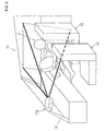
- the segmentation-processed image is transformed into a transformation-processed image C1 as shown in Fig. 5 including an occupant section 180 corresponding to the vehicle occupant C and a seat section 190 corresponding to the driver seat 12.
- step S 110 through step S 140 are carried out by the image processing means 130 shown in Fig. 1.
- the respective processes in step S110 through step S 140 may be carried by respective separate processing means.
- step S 150 a process for deriving the position of specific body region of the vehicle occupant C is conducted.
- This process is carried out by the occupant information extracting unit 151 shown in Fig. 1.
- the process selects a region corresponding to the neck region from the occupant profile obtained by the camera 112.
- this process uses body information (body feature data) previously stored in the body information storage unit 141 shown in Fig. 1. That is, a region having contour similar to the contour of the neck region which are previously stored in the body information storage unit 141 are selected as the neck region. Therefore, for example, a portion A of the processed image C1 shown in Fig. 6 is specified as the neck region, the image of Fig. 6 corresponding to the image of Fig. 5.
- This process corresponds to "associating occupant surface profile information relating to the specific body region of said vehicle occupant in the information extracted by said information extraction means with said body information which is previously stored in said storage means” or the “compares the surface profile information of said specific body region to the body surface profile information of respective body regions which are previously stored in said storage means and derives the position of said specific body region based on a result of the comparison".
- the neck region to be set as the specific body region has significant feature in surface profile. Further, its contour is hardly influenced by the slight shifting of the photographing direction of the camera 112 and its level is hardly changed relative to the movement of the vehicle occupant C. In addition, since the neck region is exposed from clothes or the like, the neck region is hardly influenced by the thickness of the clothes when it is required to detect the actual body size of the vehicle occupant. Therefore, among regions of the body, the neck region is a region especially effective to estimate the body size of the vehicle occupant C precisely. It should be noted that one or more of regions such as head, face, jaw, shoulders, arms, legs, knees, and the like other than the neck region set in this embodiment may be used in the present invention.
- the feature such as the contour of the specific body region which is previously stored in the body information storage unit 141 may be similar to the features of a plurality of regions of the processed image C1, depending on the size and the configuration of the specific body region. In this case, it is difficult to identify the specific body region. Therefore, for this case, it is effective to make a comparison relating to the positional relation between the specific body region and its peripheral regions, in addition to a comparison relating to the configuration of the specific body region.
- a condition that the neck is near the shoulders and the jaw is also employed. With this condition, the process compares the body information, which is previously stored in the body information storage unit 141, to the processed image C1, thereby precisely refining the candidate regions.
- This process corresponds to "associating occupant surface profile information relating to the specific body region of said vehicle occupant in the information extracted by said information extraction means with said body information which is previously stored in said storage means" defined in claim 1 or "compares the positional relation between the specific body region and a region around the specific body region to the positional relation between body regions which are previously stored in the storage means in addition to comparing the surface profile information of the specific body region to the body surface profile information of respective body regions which are previously stored in the storage means, and derives the position of the specific body region based on a result of the comparison" defined in claim 3.
- the specific body region may be previously set or selected from body regions taking the photographing quality of the camera 112 into consideration.
- the degree of quality or the degree of similarity of image information may be employed as criterion for determination ("criterion for determination" of the present invention). Accordingly, among a plurality of body regions, only a region having high quality image information (region having high reliability as image information) or a region of which occupant information actually obtained by the camera 112 has high similarity to the body information previously stored in the body information storage unit 141 can be set as the specific body region. Therefore, it is possible to screen out image information of which quality is decreased due to irregular posture and movement of the vehicle occupant C or abnormal optical reflection.
- step S 160 a process for deriving the position of specific seat region (vehicle-side reference region) of the driver seat 12 is conducted.
- This process is carried out by the seat information extracting unit 152 shown in Fig. 1.
- an upper portion of the seat back (generally a region between the seat back and the head rest) of the driver seat 12 is specified as the specific seat region.
- the upper portion of the seat back to be set as the specific seat region has features in its surface profile so that the position of the upper portion is presumed from the three-dimensional figure of the seat. Therefore, for example, a portion B of the processed image C 1 shown in Fig. 6 is specified as the upper portion of the seat back.
- the driver seat 12 to be set as the vehicle-side reference region is a region closely relating to the position and movement of the vehicle occupant C among respective vehicle-side regions, information about the vehicle occupant C can be detected more precisely by setting the driver seat 12 as the vehicle-side reference region.
- the upper portion of the seat back is a region having features in surface profile so as to allow easy identification of the position of the vehicle-side reference region.
- the position of the upper portion of the seat back can be presumed from information such as the seat slide position, the seat cushion height, the seat back angle, and the like obtained from these sensors.
- step S170 body size estimation process of the vehicle occupant C is conducted by using the position of the specific body region derived in step S150 and the position of the specific seat region derived in step S160. This process is conducted by the body size estimation unit 153 shown in Fig. 1.
- the seating height of the vehicle occupant C is estimated by obtaining the relative height of the neck region as the specific body region relative to the upper portion of the seat back as the specific seat region.
- the position of the upper portion of the seat back can be assumed as being positioned at a preset reference position.
- the chest thickness, the shoulder width, the configuration of the upper torso (volume, peripheral length), and the like other than the seating height of the vehicle occupant C may be estimated.
- the positions of the shoulder and chest are derived as the specific body regions in step S150 and the position of the upper portion of the seat back is derived as the specific seat region in step S160. From the positional relation in anteroposterior direction between the shoulder and the upper portion of the seat back, it is detected whether or not the back of the vehicle occupant C is in close contact with the seat back. Then, from differential distance between the position of the chest and the position of the seat back, the chest thickness is estimated.
- step S 110 By performing the aforementioned processes in step S 110 through step S 170 sequentially, the body size of the vehicle occupant C detected by the camera 112 can be estimated.
- Information as result obtained by the body size estimation process in step S170 is used for controlling an object of actuation such as the occupant restraint means 170 or is temporally stored in the estimated body size storage unit 142 of Fig. 1 in step S180 shown in Fig. 3 so that the information is read out when necessary such as for controlling the object of actuation such as the occupant restraint means 170.
- Fig. 7 is a flow chart of "occupant restraint process” in the occupant restraint system 100 of this embodiment starting at step S209 and ending at step 5241.
- the "occupant restraint process” is conducted by the photographing means 110 (camera 112), the control means 120, and the occupant restraint means 170 shown in Fig. 1.
- the photographing means 110, the control means 120, and the occupant restraint means 170 compose the "occupant restraint system" of the present invention.
- step S210 shown in Fig. 7 it is determined whether or not an airbag actuating condition is satisfied. Specifically, when danger of collision occurrence of the vehicle 10 is predicted or occurrence of actual collision is detected by a proximity sensor or a contact sensor, it is determined that the airbag actuating condition is satisfied.
- step S210 When it is determined that the airbag actuating condition is satisfied (YES in step S210), the process proceeds to step S220 where information temporally stored in the estimated body size information storage unit 142 shown in Fig. 1 is read out.
- step S230 an actuation signal is outputted to the actuating means 160 shown in Fig. 1 according to the information read out in step S220, whereby the occupant restraint means 170 is actuated (step S240).
- the signal outputted to the actuating means 160 or the occupant restraint means 170 is variable depending on the information obtained by the body size estimation process in step S 170 shown in Fig. 3, that is, the information about the body size of the vehicle occupant C. Accordingly, the restraint capability (occupant restraining mode) by the occupant restraint means 170 is varied according to the body size of the vehicle occupant.
- the occupant restraint means 170 is an airbag module comprising an inflator (gas generator) and an airbag
- the inflator is actuated in the event of a vehicle collision based on an actuation signal from the actuating means 160 so as to supply gas for deployment to the airbag.
- the pressure and flow volume of gas supplied from the inflator to the airbag are variable according to the information about the body size of the vehicle occupant C. Accordingly, the restraint capability (occupant restraining mode) by the airbag which is deployed into a region for occupant restraint is varied according to the body size of the vehicle occupant.
- the vehicle restraint system 100 of this embodiment can detect information about the vehicle occupant C precisely by performing the "occupant detection process” shown in Fig. 3.
- the occupant restraining mode by the occupant restraint means 170 can be controlled according to the reliable information about the vehicle occupant C, thereby achieving thorough restraint of the vehicle occupant C.
- this embodiment provides a vehicle 10 provided with an occupant restraint system 100 which is effective for achieving thorough restraint of a vehicle occupant.
- the present invention is not limited to the aforementioned embodiments and various applications and modifications may be made.
- the following respective embodiments based on the aforementioned embodiments may be carried out.
- the operating mode of another occupant restraint means other than the airbag module for example, the winding/unwinding mode of a seat belt and the operating mode of a warning device (indication output, audio output), may be controlled to be varied according to the "occupant detection process" of the aforementioned embodiment shown in Fig. 3.
- the present invention can employ a structure of controlling the operating mode of the occupant restraint means 170 according to the position of a body region of the vehicle occupant C and/or the positional relation (positional relation in the vehicle vertical direction, positional relation in the vehicle anteroposterior direction) and the like between the body region and the vehicle-side reference region (vehicle seat, interior panel, door, ceiling panel, steering wheel, or the like).
- the operating mode of the occupant restraint means 170 is variable according to the position of the face, the position of the chest, or the position of the neck and shoulder of the vehicle occupant C and/or the relative position in the vertical direction and the relative distance in the anteroposterior direction between the position of the specific body region and the position of the vehicle-side reference region.
- the neck region is set as the specific body region
- another region such as head, face jaw, shoulder, arm, leg, knee and the like
- the specific body region may be set as the specific body region or a plurality of regions including the neck region or a wide-range area from the head to the shoulders may be set as the specific body region in the present invention.
- the arrangement of the occupant restraint system of the present invention may be adapted to be installed not only for a vehicle occupant in a driver seat but also for a vehicle occupant in a front passenger seat and a vehicle occupant in a rear seat.
- the camera as the photographing means may be suitably installed in various vehicle body components such as an instrument panel positioned in an anterior portion of an automobile body, a pillar, a door, a windshield, a seat and the like, according to need.
- the present invention can be used for an arrangement for deriving information about a vehicle occupant seated in a vehicle seat indirectly via a child seat or a junior seat.
- the present invention can be adopted to various vehicles other than automobile such as an airplane, a boat, a train, a bus, a truck, and the like.
Abstract
Description
- The present invention relates to a technology for developing an occupant information detection system to be installed in a vehicle.
- Conventionally, an occupant restraint device is known which restrains a vehicle occupant by an air bag or the like in the event of vehicle collision. For example, disclosed in
Japanese Patent Unexamined Publication No. 2002-264747 - In an occupant restraint device of the aforementioned type for restraining an occupant in the event of a vehicle collision, a technology for obtaining precise information such as the posture and/or the body size of a vehicle occupant in a vehicle seat by using cameras is highly demanded. For example, with regard to the body size of vehicle occupant, there may be a difference between the fact and appearance due to the thickness of clothing and the like. Under this circumstance, it is required to know the actual body size of the vehicle occupant precisely. However, though the aforementioned patent document discloses the idea of estimating the state of the occupant by using a detection means, there is no description about concrete arrangement effective for grasping the posture, the body size, and the like of the vehicle occupant precisely.
- The present invention has been made in view of the above problem and it is an object of the present invention to provide an effective technology for detecting information about a vehicle occupant in a vehicle seat precisely.
- This object is achieved by an occupant information detection system according to claim 1. The dependent claims define preferred or advantageous embodiments of the detection system, an occupant restraint system and a vehicle.
- For achieving the object, the present invention is configured. Though the present invention is typically adapted to an occupant information detection system for detecting information about a vehicle occupant in a vehicle seat in an automobile, the present invention can be also adapted to a technology for developing an occupant information detection system for detecting information about a vehicle occupant in a vehicle seat of a vehicle other than the automobile. The "vehicle" used here includes various vehicles such as automobile, airplane, boat, train, bus, truck, and the like.
- The occupant information detection system of the present invention is a system for detecting information about a vehicle occupant in a vehicle seat and comprises at least a camera, an information extraction means, a storage means, and a deriving means. The "vehicle occupant" used here includes an occupant directly seated in the vehicle seat and an occupant indirectly seated in the vehicle seat via a child seat or a junior seat. In the present invention, the "information about a vehicle occupant" widely includes the body size of the vehicle occupant, the position of the vehicle occupant, the positions and configurations of respective body regions of the vehicle occupant, presence or absence of the vehicle occupant, and the like.
- The camera of the present invention is a means for obtaining an image relating to a single view point directing to the vehicle occupant. As the camera capable of obtaining an image relating to a single view point, a monocular C-MOS 3D camera or a pantoscopic stereo 3D camera may be used.
- The information extraction means of the present invention is a means for extracting information about surface profile of the vehicle occupant based on the image obtained by the camera. The information extraction means extracts (detects) presence or absence of surface profile (or contour) of the vehicle occupant and the position of the contour.
- The storage means of the present invention is a means for previously storing body information about surface profiles of a human body. As the body information to be previously stored, contours and sizes of respective body regions composing a human body, and positional relations between the body regions may be employed. Preferably, gender-based data and age-based data are stored as the body information.
- The deriving means is a means for deriving at least the position of a specific body region of the vehicle occupant by associating occupant surface profile information relating to the specific body region in the information extracted by the information extraction means with the body information which is previously stored in the storage means.
- As the "specific body region" used here, one or more of body regions such as neck, head, face, jaw, shoulder, arm, leg, knee, and the like may be employed. In the present invention, the specific body region may be set previously, or it may be set on the spot according to the reliability of information extracted by the information extraction means.
- The "occupant surface profile information relating to the specific body region" in the present invention includes information about a surface profile of the specific body region itself and surface profiles of regions around the specific body region. Therefore, the occupant surface profile information to be associated with the previously stored body information may be information about the surface profile of the specific region or the surface profile continuously formed with the plurality of regions.
- In the present invention, the deriving means may be adapted to derive not only the position of the specific body region but also the body size of the vehicle occupant, the position of the vehicle occupant, the positions and configurations of respective body regions of the vehicle occupant, presence or absence of the vehicle occupant, and the like.
- According to the arrangement of the occupant information detection system of the present invention, the occupant surface profile information relating to the specific body region of the vehicle occupant actually obtained by the camera is not used solely, but is associated with the previously stored body information about the occupant surface profiles so as to derive the position of the specific body region, thereby improving the detection reliability. Therefore, it is possible to detecting information about the vehicle occupant in the vehicle seat precisely.
- The information about the vehicle occupant detected by the occupant information detection system can be preferably used for control of occupant restraint means, for example, an airbag apparatus and a seat belt apparatus for restricting the vehicle occupant, and a warning device (indication output, audio output). Since all that is required by the present invention is the installation of a single camera which is focused on the vehicle seat with regard to the "single view point", the present invention does not preclude the installation of another camera or another view point for another purpose.
- The deriving means may be adapted to compare the surface profile information of said specific body region to the body surface profile information of respective body regions which are previously stored in the storage means and derive the position of said specific body region based on a result of the comparison.
- According to this arrangement, the position of the specific body region can be detected precisely by comparing the occupant surface profile information of the specific body region to the body surface profile information of the respective body regions which are previously stored in the storage means when deriving the position of the specific body region.
- In particular, the deriving means may be adapted to compare the positional relation between the specific body region and a region around the specific body region to the positional relation between body regions which are previously stored in the storage means in addition to comparing the surface profile information of the specific body region to the body surface profile information of respective body regions which are previously stored in the storage means, and derive the position of the specific body region based on a result of the comparison.
- In deriving the position of the specific body region, when the body surface profile information of the respective body regions which is previously stored is similar to the surface profiles of a plurality of occupant surface profiles, there are a plurality of candidates as the specific body region. In this case, it is difficult to identify the specific body region. Therefore, in the present invention, the process makes not only a comparison for the surface profile (contour) of the specific body region itself but also a comparison relating to the positional relation between the specific body region and its peripheral regions. Specifically, in addition to the feature of the contour of the neck region, a condition that the neck is near the shoulders and the jaw is also employed. With this condition, the process makes a comparison with the body information which is previously stored, thereby precisely refining the candidate regions. Therefore, this arrangement allows more precise detection of the position of the specific body region.
- Besides deriving the position of the specific body region, the deriving means may be adapted to derive information about the vehicle occupant based on the positional relation between the specific body region and a vehicle-side reference region. The "vehicle-side reference region" used here is a vehicle-side region having a position relative to the vehicle occupant. Examples of the vehicle-side reference region are a vehicle seat, an interior panel, a door, a ceiling panel, and a steering wheel. The position of the vehicle-side reference region may be detected at the same time of detection of the vehicle occupant by the camera or may be previously stored as a reference position.
- According to this arrangement, information about the vehicle occupant (body size, position of the vehicle occupant, positions and configurations of respective body regions, presence or absence of the vehicle occupant, and the like) can be derived based on the positional relation between the specific body region and the vehicle reference region. The position of the specific body region is obtained with reference to the position of the vehicle-side reference region, thereby detecting the information about the vehicle occupant precisely.
- The deriving means may be adapted such that a neck region of a person is set as the specific body region.
- Among the respective body regions, the neck region (contour around the neck) set as the specific body region has significant feature in surface profile. Further, its contour is hardly influenced by the slight shifting of the photographing direction of the camera and its level is hardly changed relative to the movement of the vehicle occupant. In addition, since the neck region is exposed from clothes or the like, the neck region is hardly influenced by the thickness of the clothes when it is required to detect the actual body size of the vehicle occupant. Therefore, among regions of the body, the neck region is a region especially effective to estimate the body size of the vehicle occupant precisely. This arrangement enables more precise detection of information about the vehicle occupant.
- The deriving means may be adapted such that the vehicle seat is set as the vehicle-side reference region.
- The vehicle seat set as the vehicle-side reference region is a region closely relating to the position and movement of the vehicle occupant seated in the vehicle seat among respective vehicle-side regions and is especially effective as a reference for the position of the vehicle occupant. Therefore, according to the arrangement in which the vehicle seat is set as the vehicle-side reference region, information about the vehicle occupant can be detected more precisely.
- With regard to the association of the occupant surface profile information relating to the specific body region of the vehicle occupant with the body information which is previously stored in the storage means, the deriving means may have a criterion for determination whether the association is valid or not. The degree of similarity between the occupant information actually obtained by the camera and the body information previously stored in the storage means or the degree of quality of image information actually obtained by the camera may be employed as the criterion for determination. Therefore, it is possible to screen out, for example, image information of which quality is decreased due to irregular posture and movement of the vehicle occupant or abnormal optical reflection. Accordingly, among a plurality of body regions, only a region having high similarity to the body information previously stored in the storage means or a region having high quality image information (region having high reliability as image information) can be set as the specific body region. This arrangement can screen information about the vehicle occupant according to the reliability when detecting information about the vehicle occupant, thereby enabling use of only information having high reliability.
- An occupant restraint system according to the invention comprises: at least an occupant information detection system as described above, a restraint means, and a control means.
- The restraint means of this invention is a means to be actuated to restrain a vehicle occupant in the event of a vehicle collision. The "restraint means" used here includes occupant restraint devices such as an airbag apparatus (airbag module) and a seat belt apparatus.
- The "control means" is a means for varying the mode for restraining the vehicle occupant by said restraint means according to information about the vehicle occupant derived by the deriving means. For example, operation (pressure, flow volume of gas, and the like) of an inflator as a gas generator for supplying gas for deploying an airbag in the event of a vehicle collision and/or operation (tension on a seat belt, winding amount and winding speed of the seat belt, and the like) of a pretensioner or a retractor for controlling the seat belt are controlled to be varied according to the information about the vehicle occupant (the body size of the vehicle occupant, the position of the vehicle occupant, the positions and configurations of respective body regions of the vehicle occupant, presence or absence of the vehicle occupant, and the like). The control means may be provided exclusively for the restraint means or used not only for the restraint means but also for other control means for controlling a running system and/or an electric system. This arrangement allows the occupant restraining mode by the restraint means to be variable according to the information about the vehicle occupant having high reliability, thereby achieving thorough restraint of the vehicle occupant.
- A vehicle according to the present invention is a vehicle comprising at least a running system including an engine, an electrical system, a drive control means, a vehicle seat, a camera, and a processing means.
- The running system including an engine is a system relating to driving of the vehicle by the engine. The electrical system is a system relating to electrical parts used in the vehicle. The drive control means is a means having a function of conducting the drive control of the running system and the electrical system. The camera has a function of obtaining an image relating to a single view point toward the vehicle seat. The processing means is a means having a function of processing information from the camera by the drive control means. In this invention, the processing means comprises an occupant information detection system as described above. The information about the vehicle occupant which is detected by the occupant information detection system is properly processed by the processing means and is used for various controls relating to the vehicle including the occupant restraint means which operates for protecting the vehicle occupant.
- According to this arrangement, a vehicle in which the information about the vehicle occupant which is precisely detected by the occupant information detection system is used for various controls relating to the vehicle can be obtained.
- As described in the above, the present invention has an arrangement of associating occupant surface profile information relating to a specific body region of a vehicle occupant, which is obtained by a camera particularly for obtaining an image relating to a single view point, with previously stored body information so as to derive the position of the specific body region, thereby enabling the precise detection of the information about the vehicle occupant in a vehicle seat.
-
- Fig. 1 is an illustration showing the arrangement of an occupant restraint system, which is installed in a vehicle, according to an embodiment.
- Fig. 2 is a perspective view showing a vehicle cabin taken from a camera side.
- Fig. 3 is a flow chart of "occupant detection process" in the occupant restraint system.
- Fig. 4 is an illustration showing an aspect of pixel segmentation in the embodiment.
- Fig. 5 is an illustration showing a processed image C1 including an occupant portion corresponding to a vehicle occupant and a seat portion corresponding to a driver seat.
- Fig. 6 is an illustration showing the processed image C1 as shown in Fig. 5, wherein a neck region is indicated as a region A and an upper portion of the seat back is indicated as a region B.
- Fig. 7 is a flow chart of "occupant restraint process" in the occupant restraint system of the embodiment.
- Hereinafter, embodiments of the present invention will be described in detail with reference to drawings. First, description will be made as regard to an
occupant restraint system 100 as an embodiment of the "occupant restraint system" according to the present invention with reference to Fig. 1 and Fig. 2. - The arrangement of the
occupant restraint system 100 to be installed in a vehicle according to this embodiment is shown in Fig. 1. - As shown in Fig. 1, the
occupant restraint system 100 of this embodiment is installed for restraining an occupant in a driver seat in an automobile which corresponds to the "vehicle" of the present invention. Theoccupant restraint system 100 mainly comprises a photographingmeans 110, a control means 120, and an occupant restraint means 170. The vehicle comprises a running system including an engine and other parts for driving the vehicle, an electrical system for electrical parts used in the vehicle, and a drive control means for conducting the drive control of the running system and the electrical system. The drive control means may be the control means 120 (corresponding to "control means" and "processing means" of the present invention) of theoccupant restraint system 100 or an exclusive control means for the running system and the electrical system. - The photographing means 110 comprises a 3D (three-dimensional)
camera 112 of a C-MOS or CCD (charge-coupled device) type in which light sensors are arranged into an array (lattice) arrangement. Thecamera 112 may be a monocular C-MOS 3D camera or a pantoscopic stereo 3D camera. Thecamera 112 is installed to be built in an instrument panel, an A-pillar, or the periphery of a windshield in a front portion of a vehicle and is disposed to face in a direction capable of photographing one or more occupants. - A perspective view of the cabin of the
vehicle 10 taken from thecamera 112 side is shown in Fig. 2 as a specific example of the installation of thecamera 112 in a cabin of avehicle 10. As shown in Fig. 2, thecamera 112 is disposed at an upper portion of an A-pillar 16 on the side of thepassenger seat 14 to face in a direction capable of photographing an occupant C (sometimes called "seated occupant" or "driver") on adriver seat 12, as the "vehicle seat" of the present invention, with focusing the camera on the occupant C. Information about the vehicle occupant C and the objects around the vehicle occupant C is detected a plurality of times periodically by using thecamera 112. Thecamera 112 corresponds to "a camera for obtaining an image relating to a single view point directing to the vehicle occupant" of the present invention. - The control means 120 comprises at least an image processing means 130, a storage means 140, a computing means (MPU: micro processing unit) 150, an actuating means 160, an input/output device, a peripheral device, and the like, but the input/output device and the peripheral device are not shown.
- The image processing means 130 is a means for processing images taken by the
camera 112. Based on distance information and position information about the photographed object, the image processing means 130 clips a three-dimensional object within a specific region of the image range and divides the object into a combination of vehicle occupant and a vehicle seat and vehicle parts other than the combination. Also in this embodiment, the image processing means 130 comprises a coordinatetransformation unit 131. The coordinatetransformation unit 131 is adapted to transform the coordinate system about thecamera 112 into a coordinate system about the vehicle body. Specifically, the coordinatetransformation unit 131 transforms a view of the vehicle occupant C taken from thecamera 112 into a view of the vehicle occupant C taken from the left side of the vehicle body. Further, the image processing means 130 is adapted to roughly recognize features of the three-dimensional object or roughly categorize the position and size of the vehicle occupant C into groups based on the volume distribution of the three-dimensional object. - The storage means 140 is a means for storing (recording) various data and the computed results to be used in the control means 120 and, in this embodiment, comprises at least a body
information storage unit 141 and an estimated body sizeinformation storage unit 142. The storage means 140 corresponds to "a storage means for previously storing body information about surface profiles of a human body" of the present invention. - The body
information storage unit 141 is adapted to previously store the body information (data of body features) such as profiles (contours) and sizes of respective body regions (for example, head, face, neck, jaw, shoulder, arm, leg, and knee) of a person and the positional relations among the body regions. The estimated body sizeinformation storage unit 142 is adapted to temporally record (store) information as a result of estimation by a bodysize estimation unit 153 as will be later. The information as a result of estimation by the bodysize estimation unit 153 is read out from the estimated body sizeinformation storage unit 142 and is suitably used for controlling the occupant restraint means 170 based on the information. - The computing means 150 comprises at least an occupant
information extracting unit 151, a seatinformation extracting unit 152, and the bodysize estimation unit 153. The computing means 150 corresponds to "a deriving means" of the present invention. - The occupant
information extracting unit 151 is adapted to extract various information relating to the vehicle occupant C based on the information processed by the image processing means 130. Specifically, the positions, distances, profiles (contours) of respective body regions (for example, head, face, neck, jaw, shoulder, arm, leg, and knee) of the vehicle occupant C, the positional relations among the body regions, and the like are extracted by the occupantinformation extracting unit 151. The occupantinformation extracting unit 151 corresponds to "an information extraction means" of the present invention. - The seat
information extracting unit 152 is adapted to extract various information relating to thedriver seat 12 based on the information processed by the image processing means 130. Specifically, the positions, distances, angles, profiles (contours), and the like of thedriver seat 12 and its components (such as a seat back, a seat cushion, a headrest and the like) are extracted by the seatinformation extracting unit 152. - The body
size estimation unit 153 is adapted to estimate the body size of the vehicle occupant C based on the information extracted by the occupantinformation extracting unit 151 and the information extracted by the seatinformation extracting unit 152. Specifically, the indexes relating to the body size such as the sitting height, the chest thickness, the shoulder width and the like of the vehicle occupant C are estimated by the bodysize estimation unit 153. When there is no information extracted by the occupantinformation extracting unit 151, the bodysize estimation unit 153 determines that "the seat is not occupied". - The actuating means 160 outputs an actuation signal (output signal) to the occupant restraint means 170 as an subject to be actuated (subject to be operated) and can vary the actuation signal to be outputted based on the estimated body size information by the body
size estimation unit 153. Therefore, the mode for restraining the vehicle occupant C by the occupant restraint means 170 when operated is variable according to the estimated body size information. Accordingly, the actuating means 160 functions as a substantial control means relative to the occupant restraint means 170. - The occupant restraint means 170 is composed of one or more of occupant restraint devices such as an airbag apparatus (airbag module) and a seat belt apparatus which operate for restraining the vehicle occupant in the event of a vehicle accident. The occupant restraint means 170 corresponds to "an occupant restraint means" of the present invention. In addition to the occupant restraint means 170, a warning device (indication output, audio output) and the like may be installed.
- In addition, an input element is installed in the
vehicle 10 to detect information about collision prediction or collision occurrence of the vehicle, information about the driving state of the vehicle, information about traffic conditions around the vehicle, information about weather condition and about time zone, and the like and to input such detected information to the control means 120, but not shown. - Hereinafter, the action of the
occupant restraint system 100 having the aforementioned arrangement will be described with reference to Fig. 3 through Fig. 7 in addition to Fig. 1 and Fig. 2. - Fig. 3 is a flow chart of "occupant detection process" in the
occupant restraint system 100 of this embodiment. In this embodiment, the "occupant detection process" is carried out by the photographing means 110 (the camera 112) and the control means 120 as shown in Fig. 1. The "occupant information detection system" of the present invention comprises the photographing means 110 and the control means 120 for detecting information about the vehicle occupant C on thedriver seat 12. The occupant detection process starts instep S 109 and ends in step S181. - In step S110 shown in Fig. 3, an image is taken by the
camera 112 in a state that thecamera 112 is generally focused on the vehicle occupant (the vehicle occupant C as shown in Fig. 2) in the driver seat. Therefore, the vehicle occupant, the driver seat, and the peripheral portions thereof are photographed by thecamera 112 and are taken as lattice-point information (for example, information of thousands or several tens of thousands of lattice points) including information about distance from thecamera 112 and the positional information. Thecamera 112 is a camera capable of detecting a three-dimensional surface profile of the vehicle occupant C from a single view point and corresponds to the "camera" of the present invention. - The
camera 112 is set to be actuated, for example, when an ignition key is turned on or when a seat sensor (not shown) installed in thedriver seat 12 detects a vehicle occupant C seated in thedriver seat 12. - Then in step S120 shown in Fig. 3, based on the information taken by the
camera 112, a three-dimensional object within a specific region of the image range is clipped, the object is divided into a combination of vehicle occupant C and avehicle seat 12 and vehicle parts other than the combination, and the positional coordinate of the three-dimensional profile of the vehicle occupant C and thedriver seat 12 is detected. - In
step S 130, a segmentation process is conducted to segment a dot image of the three-dimensional profile obtained in the step S120 into a large number of pixels. In the segmentation process, the dot image of the three-dimensional surface profile is segmented into three-dimensional lattices, for example, (X64) x (Y64) x (Z32). An aspect of pixel segmentation in this embodiment is shown in Fig. 4. As shown in Fig. 4, the center of a plane to be photographed by the camera is set as an origin, an X axis is set as lateral, a Y axis is set as vertical, and a Z axis is set as anteroposterior. With respect to the dot image of the three-dimensional profile, a certain range of the X axis and a certain range of the Y axis are segmented into respective 64 pixels, and a certain range of the Z axis is segmented into 32 pixels. It should be noted that, if a plurality of dots are superposed on the same pixel, an average is employed. According to the process, a segmentation-processed image of the three-dimensional profile is obtained. The segmentation-processed image corresponds to a perspective view of the vehicle occupant C taken from thecamera 112 and shows a coordinate system about thecamera 112. - In
step S 140, a coordinate transformation process of the segmentation-processed image obtained in the step S130 is conducted. In the coordinate transformation process, the segmentation-processed image as the coordinate system about thecamera 112 is transformed into a coordinate system about the vehicle body. Specifically, the image of the vehicle occupant C from a viewpoint of thecamera 112 is transformed into an image of the vehicle occupant C from a viewpoint of a left side of the vehicle body. That is, in transformation, the X axis is set to extend in the front-to-rear direction of the vehicle, the Y axis is set to extend in the upward direction of the vehicle, and the Z axis is set to extend in the left-to-right direction of the vehicle. Accordingly, for example, the segmentation-processed image is transformed into a transformation-processed image C1 as shown in Fig. 5 including anoccupant section 180 corresponding to the vehicle occupant C and aseat section 190 corresponding to thedriver seat 12. - These processes in step S 110 through
step S 140 are carried out by the image processing means 130 shown in Fig. 1. The respective processes in step S110 throughstep S 140 may be carried by respective separate processing means. - Then, in
step S 150, a process for deriving the position of specific body region of the vehicle occupant C is conducted. This process is carried out by the occupantinformation extracting unit 151 shown in Fig. 1. Specifically, as a neck region (contour around the neck) of the vehicle occupant C is defined as the specific body region ("specific body region" of the present invention), the process selects a region corresponding to the neck region from the occupant profile obtained by thecamera 112. In this case, this process uses body information (body feature data) previously stored in the bodyinformation storage unit 141 shown in Fig. 1. That is, a region having contour similar to the contour of the neck region which are previously stored in the bodyinformation storage unit 141 are selected as the neck region. Therefore, for example, a portion A of the processed image C1 shown in Fig. 6 is specified as the neck region, the image of Fig. 6 corresponding to the image of Fig. 5. - This process corresponds to "associating occupant surface profile information relating to the specific body region of said vehicle occupant in the information extracted by said information extraction means with said body information which is previously stored in said storage means" or the "compares the surface profile information of said specific body region to the body surface profile information of respective body regions which are previously stored in said storage means and derives the position of said specific body region based on a result of the comparison".
- In this embodiment, the neck region to be set as the specific body region has significant feature in surface profile. Further, its contour is hardly influenced by the slight shifting of the photographing direction of the
camera 112 and its level is hardly changed relative to the movement of the vehicle occupant C. In addition, since the neck region is exposed from clothes or the like, the neck region is hardly influenced by the thickness of the clothes when it is required to detect the actual body size of the vehicle occupant. Therefore, among regions of the body, the neck region is a region especially effective to estimate the body size of the vehicle occupant C precisely. It should be noted that one or more of regions such as head, face, jaw, shoulders, arms, legs, knees, and the like other than the neck region set in this embodiment may be used in the present invention. - In the aforementioned process of the step S150, the feature such as the contour of the specific body region which is previously stored in the body
information storage unit 141 may be similar to the features of a plurality of regions of the processed image C1, depending on the size and the configuration of the specific body region. In this case, it is difficult to identify the specific body region. Therefore, for this case, it is effective to make a comparison relating to the positional relation between the specific body region and its peripheral regions, in addition to a comparison relating to the configuration of the specific body region. Specifically, in addition of the feature of the contour of the neck region, a condition that the neck is near the shoulders and the jaw is also employed. With this condition, the process compares the body information, which is previously stored in the bodyinformation storage unit 141, to the processed image C1, thereby precisely refining the candidate regions. - This process corresponds to "associating occupant surface profile information relating to the specific body region of said vehicle occupant in the information extracted by said information extraction means with said body information which is previously stored in said storage means" defined in claim 1 or "compares the positional relation between the specific body region and a region around the specific body region to the positional relation between body regions which are previously stored in the storage means in addition to comparing the surface profile information of the specific body region to the body surface profile information of respective body regions which are previously stored in the storage means, and derives the position of the specific body region based on a result of the comparison" defined in claim 3.
- For comparing the body information, which is previously stored in the body
information storage unit 141, with the processed image C1, the specific body region may be previously set or selected from body regions taking the photographing quality of thecamera 112 into consideration. For example, the degree of quality or the degree of similarity of image information may be employed as criterion for determination ("criterion for determination" of the present invention). Accordingly, among a plurality of body regions, only a region having high quality image information (region having high reliability as image information) or a region of which occupant information actually obtained by thecamera 112 has high similarity to the body information previously stored in the bodyinformation storage unit 141 can be set as the specific body region. Therefore, it is possible to screen out image information of which quality is decreased due to irregular posture and movement of the vehicle occupant C or abnormal optical reflection. - In
step S 160 following the aforementioned step S150, a process for deriving the position of specific seat region (vehicle-side reference region) of thedriver seat 12 is conducted. This process is carried out by the seatinformation extracting unit 152 shown in Fig. 1. Specifically, an upper portion of the seat back (generally a region between the seat back and the head rest) of thedriver seat 12 is specified as the specific seat region. The upper portion of the seat back to be set as the specific seat region has features in its surface profile so that the position of the upper portion is presumed from the three-dimensional figure of the seat. Therefore, for example, a portion B of the processed image C 1 shown in Fig. 6 is specified as the upper portion of the seat back. Since thedriver seat 12 to be set as the vehicle-side reference region is a region closely relating to the position and movement of the vehicle occupant C among respective vehicle-side regions, information about the vehicle occupant C can be detected more precisely by setting thedriver seat 12 as the vehicle-side reference region. Among the respective regions of thedriver seat 12, the upper portion of the seat back is a region having features in surface profile so as to allow easy identification of the position of the vehicle-side reference region. - When a seat slide position detection sensor, a seat cushion height detection sensor, a seat back angle detection sensor, and the like are installed, the position of the upper portion of the seat back can be presumed from information such as the seat slide position, the seat cushion height, the seat back angle, and the like obtained from these sensors.
- In step S170, body size estimation process of the vehicle occupant C is conducted by using the position of the specific body region derived in step S150 and the position of the specific seat region derived in step S160. This process is conducted by the body
size estimation unit 153 shown in Fig. 1. - Specifically, the seating height of the vehicle occupant C is estimated by obtaining the relative height of the neck region as the specific body region relative to the upper portion of the seat back as the specific seat region. When the position of the upper portion of the seat back is not derived, the position of the upper portion of the seat back can be assumed as being positioned at a preset reference position.
- Relating to the body size estimation process in the
step S 170, the chest thickness, the shoulder width, the configuration of the upper torso (volume, peripheral length), and the like other than the seating height of the vehicle occupant C may be estimated. - For example, for estimating the chest thickness of the vehicle occupant C, the positions of the shoulder and chest are derived as the specific body regions in step S150 and the position of the upper portion of the seat back is derived as the specific seat region in step S160. From the positional relation in anteroposterior direction between the shoulder and the upper portion of the seat back, it is detected whether or not the back of the vehicle occupant C is in close contact with the seat back. Then, from differential distance between the position of the chest and the position of the seat back, the chest thickness is estimated.
- By performing the aforementioned processes in step S 110 through
step S 170 sequentially, the body size of the vehicle occupant C detected by thecamera 112 can be estimated. Information as result obtained by the body size estimation process in step S170 is used for controlling an object of actuation such as the occupant restraint means 170 or is temporally stored in the estimated bodysize storage unit 142 of Fig. 1 in step S180 shown in Fig. 3 so that the information is read out when necessary such as for controlling the object of actuation such as the occupant restraint means 170. - Fig. 7 is a flow chart of "occupant restraint process" in the
occupant restraint system 100 of this embodiment starting at step S209 and ending at step 5241. In this embodiment, the "occupant restraint process" is conducted by the photographing means 110 (camera 112), the control means 120, and the occupant restraint means 170 shown in Fig. 1. The photographing means 110, the control means 120, and the occupant restraint means 170 compose the "occupant restraint system" of the present invention. - In step S210 shown in Fig. 7, it is determined whether or not an airbag actuating condition is satisfied. Specifically, when danger of collision occurrence of the
vehicle 10 is predicted or occurrence of actual collision is detected by a proximity sensor or a contact sensor, it is determined that the airbag actuating condition is satisfied. - When it is determined that the airbag actuating condition is satisfied (YES in step S210), the process proceeds to step S220 where information temporally stored in the estimated body size
information storage unit 142 shown in Fig. 1 is read out. In step S230, an actuation signal is outputted to the actuating means 160 shown in Fig. 1 according to the information read out in step S220, whereby the occupant restraint means 170 is actuated (step S240). In this embodiment, the signal outputted to the actuating means 160 or the occupant restraint means 170 is variable depending on the information obtained by the body size estimation process instep S 170 shown in Fig. 3, that is, the information about the body size of the vehicle occupant C. Accordingly, the restraint capability (occupant restraining mode) by the occupant restraint means 170 is varied according to the body size of the vehicle occupant. - As an example, in case where the occupant restraint means 170 is an airbag module comprising an inflator (gas generator) and an airbag, the inflator is actuated in the event of a vehicle collision based on an actuation signal from the actuating means 160 so as to supply gas for deployment to the airbag. The pressure and flow volume of gas supplied from the inflator to the airbag are variable according to the information about the body size of the vehicle occupant C. Accordingly, the restraint capability (occupant restraining mode) by the airbag which is deployed into a region for occupant restraint is varied according to the body size of the vehicle occupant.
- As mentioned above, the
vehicle restraint system 100 of this embodiment can detect information about the vehicle occupant C precisely by performing the "occupant detection process" shown in Fig. 3. In addition, by performing the "occupant restraint process" shown in Fig. 7, the occupant restraining mode by the occupant restraint means 170 can be controlled according to the reliable information about the vehicle occupant C, thereby achieving thorough restraint of the vehicle occupant C. - Further, this embodiment provides a
vehicle 10 provided with anoccupant restraint system 100 which is effective for achieving thorough restraint of a vehicle occupant. - The present invention is not limited to the aforementioned embodiments and various applications and modifications may be made. For example, the following respective embodiments based on the aforementioned embodiments may be carried out.
- In the present invention, the operating mode of another occupant restraint means other than the airbag module, for example, the winding/unwinding mode of a seat belt and the operating mode of a warning device (indication output, audio output), may be controlled to be varied according to the "occupant detection process" of the aforementioned embodiment shown in Fig. 3.
- Besides the aforementioned structure of controlling the operating mode of the occupant restraint means 170 according to the body size information of the vehicle occupant C as the "occupant restraint process" of the aforementioned embodiment shown in Fig. 7, the present invention can employ a structure of controlling the operating mode of the occupant restraint means 170 according to the position of a body region of the vehicle occupant C and/or the positional relation (positional relation in the vehicle vertical direction, positional relation in the vehicle anteroposterior direction) and the like between the body region and the vehicle-side reference region (vehicle seat, interior panel, door, ceiling panel, steering wheel, or the like). Specifically, the operating mode of the occupant restraint means 170 is variable according to the position of the face, the position of the chest, or the position of the neck and shoulder of the vehicle occupant C and/or the relative position in the vertical direction and the relative distance in the anteroposterior direction between the position of the specific body region and the position of the vehicle-side reference region.
- Though the aforementioned embodiment has been described with regard to a case where the neck region is set as the specific body region, another region (such as head, face jaw, shoulder, arm, leg, knee and the like) other than the neck region may be set as the specific body region or a plurality of regions including the neck region or a wide-range area from the head to the shoulders may be set as the specific body region in the present invention.
- Though the aforementioned embodiment has been described with regard to the
occupant restraint system 100 to be installed for a vehicle occupant in the driver seat, the arrangement of the occupant restraint system of the present invention may be adapted to be installed not only for a vehicle occupant in a driver seat but also for a vehicle occupant in a front passenger seat and a vehicle occupant in a rear seat. In this case, the camera as the photographing means may be suitably installed in various vehicle body components such as an instrument panel positioned in an anterior portion of an automobile body, a pillar, a door, a windshield, a seat and the like, according to need. - Though the aforementioned embodiment has been described with regard to a case for deriving information about the vehicle occupant C directly seated in the
driver seat 12, the present invention can be used for an arrangement for deriving information about a vehicle occupant seated in a vehicle seat indirectly via a child seat or a junior seat. - Though the aforementioned embodiment has been described with regard to the arrangement of the occupant restraint system to be installed in an automobile, the present invention can be adopted to various vehicles other than automobile such as an airplane, a boat, a train, a bus, a truck, and the like.
Claims (9)
- An occupant information detection system for detecting information about a vehicle occupant in a vehicle seat, said detection system comprising:a camera (112) for obtaining an image relating to a single view point directing to said vehicle occupant (C);an information extraction means (151) for extracting information about a surface profile of said vehicle occupant based on the image obtained by said camera;a storage means (140) for previously storing body information about surface profiles of a human body; anda deriving means (150) for deriving the position of a specific body region by associating occupant surface profile information relating to the specific body region of said vehicle occupant (C) in the information extracted by said information extraction means (151) with said body information which is previously stored in said storage means (140).
- An occupant information detection system as claimed in claim 1, wherein
said deriving means (150) compares the surface profile information of said specific body region to the body surface profile information of respective body regions which are previously stored in said storage means (140) and derives the position of said specific body region based on a result of the comparison. - An occupant information detection system as claimed in claim 2, wherein
said deriving means (150) compares the positional relation between said specific body region and a region around said specific body region to the positional relation between body regions which are previously stored in said storage means in addition to comparing the surface profile information of said specific body region to the body surface profile information of respective body regions which are previously stored in said storage means (140), and derives the position of said specific body region based on a result of the comparison. - An occupant information detection system as claimed in any one of claims 1 through 3, wherein
besides deriving the position of said specific body region, said deriving means (150) is adapted to derive information about said vehicle occupant (C) based on the positional relation between said specific body region and a vehicle-side reference region (12). - An occupant information detection system as claimed in claim 4, wherein
said deriving means (150) is adapted such that said vehicle seat (12) is set as said vehicle-side reference region - An occupant information detection system as claimed in any one of claims 1 through 5, wherein
said deriving means (150) is adapted such that a neck region of a person is set as said specific body region. - An occupant information detection system as claimed in any one of claims 1 through 6, wherein
with regard to the association of the occupant surface profile information relating to the specific body region of said vehicle occupant (C) with the body information which is previously stored in said storage means (140), said deriving means (150) has a criterion for determination whether said association is valid or not. - An occupant restraint system (100) comprising:an occupant information detection system as claimed in any one of claims 1 through 7;a restraint means (170) for restraining a vehicle occupant (C) in the event of a vehicle collision; anda control means (120) for varying the mode for restraining the vehicle occupant (C) by said restraint means (170) according to information about said vehicle occupant (C) derived by said deriving means (150).
- A vehicle comprising a running system including an engine; an electrical system; a drive control means for conducting the drive control of said running system and said electrical system; a vehicle seat (12); a camera (112) for obtaining an image relating to a single view point directing to said vehicle occupant (C); and a processing means (120) for processing information from said camera by said drive control means, wherein
said processing means (120) comprises an occupant detection system as claimed in any one of claims 1 through 7.
Applications Claiming Priority (1)
| Application Number | Priority Date | Filing Date | Title |
|---|---|---|---|
| JP2005208990A JP2007022401A (en) | 2005-07-19 | 2005-07-19 | Occupant information detection system, occupant restraint device and vehicle |
Publications (3)
| Publication Number | Publication Date |
|---|---|
| EP1746527A2 true EP1746527A2 (en) | 2007-01-24 |
| EP1746527A3 EP1746527A3 (en) | 2007-06-20 |
| EP1746527B1 EP1746527B1 (en) | 2009-10-28 |
Family
ID=37137471
Family Applications (1)
| Application Number | Title | Priority Date | Filing Date |
|---|---|---|---|
| EP06014047A Expired - Fee Related EP1746527B1 (en) | 2005-07-19 | 2006-07-06 | Occupant information detection system, occupant restraint system, and vehicle |
Country Status (5)
| Country | Link |
|---|---|
| US (1) | US7630804B2 (en) |
| EP (1) | EP1746527B1 (en) |
| JP (1) | JP2007022401A (en) |
| CN (1) | CN1899890A (en) |
| DE (1) | DE602006009989D1 (en) |
Cited By (2)
| Publication number | Priority date | Publication date | Assignee | Title |
|---|---|---|---|---|
| EP1870295A1 (en) * | 2006-06-20 | 2007-12-26 | Takata Corporation | Vehicle occupant detecting system, operation device controlling system, and vehicle |
| US7978881B2 (en) | 2007-04-24 | 2011-07-12 | Takata Corporation | Occupant information detection system |
Families Citing this family (32)
| Publication number | Priority date | Publication date | Assignee | Title |
|---|---|---|---|---|
| JP2006176075A (en) * | 2004-12-24 | 2006-07-06 | Tkj Kk | Detection system, occupant protection device, vehicle and detection method |
| JP5215549B2 (en) | 2006-11-24 | 2013-06-19 | タカタ株式会社 | Seat belt retractor |
| JP2008230366A (en) * | 2007-03-19 | 2008-10-02 | Toyota Motor Corp | Driving posture automatic adjustment device and adjusting method of driving posture automatic adjustment device |
| US8391554B2 (en) * | 2008-10-01 | 2013-03-05 | GM Global Technology Operations LLC | Eye detection system using a single camera |
| US20100182425A1 (en) * | 2009-01-21 | 2010-07-22 | Mazda Motor Corporation | Vehicle interior state recognition device |
| JP2010195139A (en) * | 2009-02-24 | 2010-09-09 | Takata Corp | Occupant restraint control device and occupant restraint control method |
| US9511683B2 (en) * | 2010-08-25 | 2016-12-06 | GM Global Technology Operations LLC | Occupant recognition and verification system |
| US8789849B2 (en) | 2011-05-17 | 2014-07-29 | Tk Holdings Inc. | Dual depth airbag |
| KR101782469B1 (en) | 2011-07-11 | 2017-09-27 | 현대모비스 주식회사 | Passenger Sensing System based on image information and Method Thereof |
| JP5692049B2 (en) * | 2011-12-26 | 2015-04-01 | 株式会社デンソー | Steering position control system |
| US9902340B2 (en) * | 2011-12-29 | 2018-02-27 | Intel Corporation | Systems, methods, and apparatus for enhancing a camera field of view in a vehicle |
| CN102555982B (en) * | 2012-01-20 | 2013-10-23 | 江苏大学 | Safety belt wearing identification method and device based on machine vision |
| CN104118384B (en) * | 2013-04-26 | 2016-08-10 | 国网山东省电力公司临清市供电公司 | Air bag starts control system and method |
| DE102013209601A1 (en) * | 2013-05-23 | 2014-12-11 | Ford Global Technologies, Llc | Method and apparatus for detecting and responding to neck stiffness problems in motor vehicle occupants |
| JP2013252863A (en) * | 2013-09-27 | 2013-12-19 | Takata Corp | Occupant restriction control device and occupant restriction control method |
| KR102114386B1 (en) * | 2013-11-21 | 2020-05-22 | 현대모비스 주식회사 | Mirrorless System for Vehicle |
| JP6342302B2 (en) * | 2014-11-10 | 2018-06-13 | トヨタ紡織株式会社 | Vehicle control method |
| WO2016199311A1 (en) * | 2015-06-10 | 2016-12-15 | 株式会社Doog | Mobile chassis |
| US9908625B2 (en) * | 2015-08-06 | 2018-03-06 | Ami Industries, Inc. | Occupant restraint system and method of operating |
| DE102016113933A1 (en) * | 2015-08-17 | 2017-02-23 | Ford Global Technologies, Llc | System and method for occupant size |
| US10604259B2 (en) | 2016-01-20 | 2020-03-31 | Amsafe, Inc. | Occupant restraint systems having extending restraints, and associated systems and methods |
| JP6798299B2 (en) | 2016-12-16 | 2020-12-09 | アイシン精機株式会社 | Crew detector |
| CN111867466A (en) * | 2018-03-22 | 2020-10-30 | 三菱电机株式会社 | Physique estimation device and physique estimation method |
| JP7210965B2 (en) * | 2018-09-26 | 2023-01-24 | 株式会社アイシン | indoor monitoring device |
| JP7040387B2 (en) * | 2018-09-27 | 2022-03-23 | トヨタ自動車株式会社 | Vehicle seat system |
| DE102018218215A1 (en) * | 2018-10-24 | 2020-04-30 | Robert Bosch Gmbh | Occupant monitoring system for a vehicle |
| JP7375456B2 (en) * | 2019-10-18 | 2023-11-08 | 株式会社アイシン | Toe position estimation device and fingertip position estimation device |
| CN111275002A (en) * | 2020-02-18 | 2020-06-12 | 上海商汤临港智能科技有限公司 | Image processing method and device and electronic equipment |
| US11590980B2 (en) * | 2020-05-22 | 2023-02-28 | Pony Ai Inc. | Automated responses to vehicle trunk entrapment |
| FR3119131A1 (en) | 2021-01-22 | 2022-07-29 | Commissariat A L'energie Atomique Et Aux Energies Alternatives | System and method for estimating the height of a user of a seat and a method of manufacturing such a system |
| CN113487830A (en) * | 2021-06-25 | 2021-10-08 | 东风柳州汽车有限公司 | Vehicle safety early warning method, device, storage medium and device |
| KR102616328B1 (en) * | 2021-12-27 | 2023-12-21 | 현대모비스 주식회사 | Apparatus and method for judging seat belt wearing |
Citations (1)
| Publication number | Priority date | Publication date | Assignee | Title |
|---|---|---|---|---|
| JP2002264747A (en) | 2001-03-07 | 2002-09-18 | Nissan Motor Co Ltd | Occupant constraining device for vehicle |
Family Cites Families (19)
| Publication number | Priority date | Publication date | Assignee | Title |
|---|---|---|---|---|
| US6772057B2 (en) * | 1995-06-07 | 2004-08-03 | Automotive Technologies International, Inc. | Vehicular monitoring systems using image processing |
| US6029105A (en) * | 1996-09-09 | 2000-02-22 | Trw Automotive Electronics & Components Gmbh & Co. Kg | Method and apparatus for detecting and monitoring a partial space |
| US6027138A (en) * | 1996-09-19 | 2000-02-22 | Fuji Electric Co., Ltd. | Control method for inflating air bag for an automobile |
| US5983147A (en) * | 1997-02-06 | 1999-11-09 | Sandia Corporation | Video occupant detection and classification |
| US6005958A (en) * | 1997-04-23 | 1999-12-21 | Automotive Systems Laboratory, Inc. | Occupant type and position detection system |
| JP4031122B2 (en) * | 1998-09-30 | 2008-01-09 | 本田技研工業株式会社 | Object detection device using difference image |
| JP2002008021A (en) * | 2000-06-16 | 2002-01-11 | Tokai Rika Co Ltd | Occupant detection system |
| US6493620B2 (en) * | 2001-04-18 | 2002-12-10 | Eaton Corporation | Motor vehicle occupant detection system employing ellipse shape models and bayesian classification |
| US6662093B2 (en) * | 2001-05-30 | 2003-12-09 | Eaton Corporation | Image processing system for detecting when an airbag should be deployed |
| JP2003052039A (en) * | 2001-08-07 | 2003-02-21 | Suzuki Motor Corp | System and method for measuring work motion, and program for measurement of work motion |
| JP3943367B2 (en) * | 2001-10-31 | 2007-07-11 | 株式会社デンソー | Vehicle occupant head detection device |
| JP3829729B2 (en) * | 2002-02-14 | 2006-10-04 | オムロン株式会社 | Personal authentication device |
| JP2003259359A (en) * | 2002-03-06 | 2003-09-12 | Nissan Motor Co Ltd | Apparatus and method for monitoring surrounding of vehicle |
| US7123747B2 (en) * | 2002-05-28 | 2006-10-17 | Trw Inc. | Enhancement of vehicle interior digital images |
| DE10226257A1 (en) * | 2002-06-13 | 2003-12-24 | Bosch Gmbh Robert | Method for detecting a person in a room |
| JP2004053324A (en) * | 2002-07-17 | 2004-02-19 | Denso Corp | Collision safety controller for automobile |
| JP4261217B2 (en) * | 2003-02-25 | 2009-04-30 | 株式会社東海理化電機製作所 | Vehicle power supply control device |
| JP3781021B2 (en) * | 2003-07-30 | 2006-05-31 | 日産自動車株式会社 | Crew position detection device |
| JP2006176075A (en) | 2004-12-24 | 2006-07-06 | Tkj Kk | Detection system, occupant protection device, vehicle and detection method |
-
2005
- 2005-07-19 JP JP2005208990A patent/JP2007022401A/en active Pending
-
2006
- 2006-07-06 EP EP06014047A patent/EP1746527B1/en not_active Expired - Fee Related
- 2006-07-06 DE DE602006009989T patent/DE602006009989D1/en active Active
- 2006-07-19 CN CNA2006101061493A patent/CN1899890A/en active Pending
- 2006-07-19 US US11/458,505 patent/US7630804B2/en not_active Expired - Fee Related
Patent Citations (1)
| Publication number | Priority date | Publication date | Assignee | Title |
|---|---|---|---|---|
| JP2002264747A (en) | 2001-03-07 | 2002-09-18 | Nissan Motor Co Ltd | Occupant constraining device for vehicle |
Cited By (2)
| Publication number | Priority date | Publication date | Assignee | Title |
|---|---|---|---|---|
| EP1870295A1 (en) * | 2006-06-20 | 2007-12-26 | Takata Corporation | Vehicle occupant detecting system, operation device controlling system, and vehicle |
| US7978881B2 (en) | 2007-04-24 | 2011-07-12 | Takata Corporation | Occupant information detection system |
Also Published As
| Publication number | Publication date |
|---|---|
| CN1899890A (en) | 2007-01-24 |
| EP1746527B1 (en) | 2009-10-28 |
| EP1746527A3 (en) | 2007-06-20 |
| US20080021616A1 (en) | 2008-01-24 |
| DE602006009989D1 (en) | 2009-12-10 |
| US7630804B2 (en) | 2009-12-08 |
| JP2007022401A (en) | 2007-02-01 |
Similar Documents
| Publication | Publication Date | Title |
|---|---|---|
| EP1746527B1 (en) | Occupant information detection system, occupant restraint system, and vehicle | |
| EP1674347B1 (en) | Detection system, occupant protection device, vehicle, and detection method | |
| US7920722B2 (en) | Occupant detection apparatus | |
| US7978881B2 (en) | Occupant information detection system | |
| US20080255731A1 (en) | Occupant detection apparatus | |
| EP1759932B1 (en) | Method of classifying vehicle occupants | |
| US10501048B2 (en) | Seatbelt buckling detection | |
| EP1693254B1 (en) | Detection system, informing system, actuation system and vehicle | |
| EP1870295A1 (en) | Vehicle occupant detecting system, operation device controlling system, and vehicle | |
| US6757009B1 (en) | Apparatus for detecting the presence of an occupant in a motor vehicle | |
| EP1842734A2 (en) | Objekt detecting system, actuating device control system, vehicle, and object detecting method | |
| US20070055427A1 (en) | Vision-based occupant classification method and system for controlling airbag deployment in a vehicle restraint system | |
| CN113459982B (en) | System and method for occupant classification and adjusting airbag deployment based thereon | |
| EP1842735A2 (en) | Object detecting system, actuating device control system, vehicle, and object detecting method | |
| JP4469508B2 (en) | Method and apparatus for determining the position of an object in a scene | |
| CN110402211B (en) | Passenger protection control device, passenger protection control method, and storage medium | |
| US20060149426A1 (en) | Detecting an eye of a user and determining location and blinking state of the user | |
| JP2010203836A (en) | Vehicle interior state recognition device | |
| JP3829474B2 (en) | Vehicle occupant protection device | |
| CN114987380A (en) | Method for occupant protection and occupant protection system | |
| JP2001331790A (en) | Crew detecting system | |
| KR102537668B1 (en) | Apparatus for protecting passenger on vehicle and control method thereof | |
| JP2018156212A (en) | Physique determination device, physique determination method and program | |
| GB2622599A (en) | Method and system for detecting a seatbelt status of a vehicle seat | |
| CN115416547A (en) | Vehicle seat adjusting method, device, equipment and storage medium |
Legal Events
| Date | Code | Title | Description |
|---|---|---|---|
| PUAI | Public reference made under article 153(3) epc to a published international application that has entered the european phase |
Free format text: ORIGINAL CODE: 0009012 |
|
| AK | Designated contracting states |
Kind code of ref document: A2 Designated state(s): AT BE BG CH CY CZ DE DK EE ES FI FR GB GR HU IE IS IT LI LT LU LV MC NL PL PT RO SE SI SK TR |
|
| AX | Request for extension of the european patent |
Extension state: AL BA HR MK YU |
|
| PUAL | Search report despatched |
Free format text: ORIGINAL CODE: 0009013 |
|
| AK | Designated contracting states |
Kind code of ref document: A3 Designated state(s): AT BE BG CH CY CZ DE DK EE ES FI FR GB GR HU IE IS IT LI LT LU LV MC NL PL PT RO SE SI SK TR |
|
| AX | Request for extension of the european patent |
Extension state: AL BA HR MK YU |
|
| RIC1 | Information provided on ipc code assigned before grant |
Ipc: G06K 9/20 20060101ALI20070516BHEP Ipc: G06K 9/00 20060101AFI20061031BHEP Ipc: B60R 21/015 20060101ALI20070516BHEP |
|
| 17P | Request for examination filed |
Effective date: 20071214 |
|
| 17Q | First examination report despatched |
Effective date: 20080121 |
|
| AKX | Designation fees paid |
Designated state(s): DE FR GB |
|
| GRAP | Despatch of communication of intention to grant a patent |
Free format text: ORIGINAL CODE: EPIDOSNIGR1 |
|
| GRAS | Grant fee paid |
Free format text: ORIGINAL CODE: EPIDOSNIGR3 |
|
| GRAA | (expected) grant |
Free format text: ORIGINAL CODE: 0009210 |
|
| AK | Designated contracting states |
Kind code of ref document: B1 Designated state(s): DE FR GB |
|
| REG | Reference to a national code |
Ref country code: GB Ref legal event code: FG4D |
|
| REF | Corresponds to: |
Ref document number: 602006009989 Country of ref document: DE Date of ref document: 20091210 Kind code of ref document: P |
|
| PLBE | No opposition filed within time limit |
Free format text: ORIGINAL CODE: 0009261 |
|
| STAA | Information on the status of an ep patent application or granted ep patent |
Free format text: STATUS: NO OPPOSITION FILED WITHIN TIME LIMIT |
|
| 26N | No opposition filed |
Effective date: 20100729 |
|
| REG | Reference to a national code |
Ref country code: FR Ref legal event code: ST Effective date: 20110331 |
|
| PG25 | Lapsed in a contracting state [announced via postgrant information from national office to epo] |
Ref country code: FR Free format text: LAPSE BECAUSE OF NON-PAYMENT OF DUE FEES Effective date: 20100802 |
|
| PGFP | Annual fee paid to national office [announced via postgrant information from national office to epo] |
Ref country code: DE Payment date: 20130703 Year of fee payment: 8 |
|
| PGFP | Annual fee paid to national office [announced via postgrant information from national office to epo] |
Ref country code: GB Payment date: 20130703 Year of fee payment: 8 |
|
| REG | Reference to a national code |
Ref country code: DE Ref legal event code: R119 Ref document number: 602006009989 Country of ref document: DE |
|
| GBPC | Gb: european patent ceased through non-payment of renewal fee |
Effective date: 20140706 |
|
| PG25 | Lapsed in a contracting state [announced via postgrant information from national office to epo] |
Ref country code: DE Free format text: LAPSE BECAUSE OF NON-PAYMENT OF DUE FEES Effective date: 20150203 |
|
| REG | Reference to a national code |
Ref country code: DE Ref legal event code: R119 Ref document number: 602006009989 Country of ref document: DE Effective date: 20150203 |
|
| PG25 | Lapsed in a contracting state [announced via postgrant information from national office to epo] |
Ref country code: GB Free format text: LAPSE BECAUSE OF NON-PAYMENT OF DUE FEES Effective date: 20140706 |