EP1750676B1 - Ingestible device platform for the colon - Google Patents
Ingestible device platform for the colon Download PDFInfo
- Publication number
- EP1750676B1 EP1750676B1 EP05740562.3A EP05740562A EP1750676B1 EP 1750676 B1 EP1750676 B1 EP 1750676B1 EP 05740562 A EP05740562 A EP 05740562A EP 1750676 B1 EP1750676 B1 EP 1750676B1
- Authority
- EP
- European Patent Office
- Prior art keywords
- colon
- ingestible
- pill
- imaging
- ingestible pill
- Prior art date
- Legal status (The legal status is an assumption and is not a legal conclusion. Google has not performed a legal analysis and makes no representation as to the accuracy of the status listed.)
- Active
Links
Images


Classifications
-
- A—HUMAN NECESSITIES
- A61—MEDICAL OR VETERINARY SCIENCE; HYGIENE
- A61B—DIAGNOSIS; SURGERY; IDENTIFICATION
- A61B1/00—Instruments for performing medical examinations of the interior of cavities or tubes of the body by visual or photographical inspection, e.g. endoscopes; Illuminating arrangements therefor
- A61B1/00147—Holding or positioning arrangements
- A61B1/00156—Holding or positioning arrangements using self propulsion
-
- A—HUMAN NECESSITIES
- A61—MEDICAL OR VETERINARY SCIENCE; HYGIENE
- A61B—DIAGNOSIS; SURGERY; IDENTIFICATION
- A61B1/00—Instruments for performing medical examinations of the interior of cavities or tubes of the body by visual or photographical inspection, e.g. endoscopes; Illuminating arrangements therefor
- A61B1/04—Instruments for performing medical examinations of the interior of cavities or tubes of the body by visual or photographical inspection, e.g. endoscopes; Illuminating arrangements therefor combined with photographic or television appliances
- A61B1/041—Capsule endoscopes for imaging
-
- A—HUMAN NECESSITIES
- A61—MEDICAL OR VETERINARY SCIENCE; HYGIENE
- A61B—DIAGNOSIS; SURGERY; IDENTIFICATION
- A61B5/00—Measuring for diagnostic purposes; Identification of persons
- A61B5/0059—Measuring for diagnostic purposes; Identification of persons using light, e.g. diagnosis by transillumination, diascopy, fluorescence
- A61B5/0077—Devices for viewing the surface of the body, e.g. camera, magnifying lens
-
- A—HUMAN NECESSITIES
- A61—MEDICAL OR VETERINARY SCIENCE; HYGIENE
- A61B—DIAGNOSIS; SURGERY; IDENTIFICATION
- A61B5/00—Measuring for diagnostic purposes; Identification of persons
- A61B5/145—Measuring characteristics of blood in vivo, e.g. gas concentration, pH value; Measuring characteristics of body fluids or tissues, e.g. interstitial fluid, cerebral tissue
- A61B5/14539—Measuring characteristics of blood in vivo, e.g. gas concentration, pH value; Measuring characteristics of body fluids or tissues, e.g. interstitial fluid, cerebral tissue for measuring pH
-
- A—HUMAN NECESSITIES
- A61—MEDICAL OR VETERINARY SCIENCE; HYGIENE
- A61B—DIAGNOSIS; SURGERY; IDENTIFICATION
- A61B5/00—Measuring for diagnostic purposes; Identification of persons
- A61B5/145—Measuring characteristics of blood in vivo, e.g. gas concentration, pH value; Measuring characteristics of body fluids or tissues, e.g. interstitial fluid, cerebral tissue
- A61B5/1455—Measuring characteristics of blood in vivo, e.g. gas concentration, pH value; Measuring characteristics of body fluids or tissues, e.g. interstitial fluid, cerebral tissue using optical sensors, e.g. spectral photometrical oximeters
- A61B5/1459—Measuring characteristics of blood in vivo, e.g. gas concentration, pH value; Measuring characteristics of body fluids or tissues, e.g. interstitial fluid, cerebral tissue using optical sensors, e.g. spectral photometrical oximeters invasive, e.g. introduced into the body by a catheter
-
- A—HUMAN NECESSITIES
- A61—MEDICAL OR VETERINARY SCIENCE; HYGIENE
- A61B—DIAGNOSIS; SURGERY; IDENTIFICATION
- A61B5/00—Measuring for diagnostic purposes; Identification of persons
- A61B5/41—Detecting, measuring or recording for evaluating the immune or lymphatic systems
- A61B5/414—Evaluating particular organs or parts of the immune or lymphatic systems
- A61B5/415—Evaluating particular organs or parts of the immune or lymphatic systems the glands, e.g. tonsils, adenoids or thymus
-
- A—HUMAN NECESSITIES
- A61—MEDICAL OR VETERINARY SCIENCE; HYGIENE
- A61B—DIAGNOSIS; SURGERY; IDENTIFICATION
- A61B5/00—Measuring for diagnostic purposes; Identification of persons
- A61B5/42—Detecting, measuring or recording for evaluating the gastrointestinal, the endocrine or the exocrine systems
- A61B5/4222—Evaluating particular parts, e.g. particular organs
- A61B5/4255—Intestines, colon or appendix
-
- A—HUMAN NECESSITIES
- A61—MEDICAL OR VETERINARY SCIENCE; HYGIENE
- A61B—DIAGNOSIS; SURGERY; IDENTIFICATION
- A61B5/00—Measuring for diagnostic purposes; Identification of persons
- A61B5/68—Arrangements of detecting, measuring or recording means, e.g. sensors, in relation to patient
- A61B5/6846—Arrangements of detecting, measuring or recording means, e.g. sensors, in relation to patient specially adapted to be brought in contact with an internal body part, i.e. invasive
- A61B5/6847—Arrangements of detecting, measuring or recording means, e.g. sensors, in relation to patient specially adapted to be brought in contact with an internal body part, i.e. invasive mounted on an invasive device
- A61B5/6861—Capsules, e.g. for swallowing or implanting
-
- A—HUMAN NECESSITIES
- A61—MEDICAL OR VETERINARY SCIENCE; HYGIENE
- A61B—DIAGNOSIS; SURGERY; IDENTIFICATION
- A61B6/00—Apparatus for radiation diagnosis, e.g. combined with radiation therapy equipment
- A61B6/42—Apparatus for radiation diagnosis, e.g. combined with radiation therapy equipment with arrangements for detecting radiation specially adapted for radiation diagnosis
- A61B6/4208—Apparatus for radiation diagnosis, e.g. combined with radiation therapy equipment with arrangements for detecting radiation specially adapted for radiation diagnosis characterised by using a particular type of detector
- A61B6/425—Apparatus for radiation diagnosis, e.g. combined with radiation therapy equipment with arrangements for detecting radiation specially adapted for radiation diagnosis characterised by using a particular type of detector using detectors specially adapted to be used in the interior of the body
-
- A—HUMAN NECESSITIES
- A61—MEDICAL OR VETERINARY SCIENCE; HYGIENE
- A61B—DIAGNOSIS; SURGERY; IDENTIFICATION
- A61B6/00—Apparatus for radiation diagnosis, e.g. combined with radiation therapy equipment
- A61B6/42—Apparatus for radiation diagnosis, e.g. combined with radiation therapy equipment with arrangements for detecting radiation specially adapted for radiation diagnosis
- A61B6/4208—Apparatus for radiation diagnosis, e.g. combined with radiation therapy equipment with arrangements for detecting radiation specially adapted for radiation diagnosis characterised by using a particular type of detector
- A61B6/4258—Apparatus for radiation diagnosis, e.g. combined with radiation therapy equipment with arrangements for detecting radiation specially adapted for radiation diagnosis characterised by using a particular type of detector for detecting non x-ray radiation, e.g. gamma radiation
-
- A—HUMAN NECESSITIES
- A61—MEDICAL OR VETERINARY SCIENCE; HYGIENE
- A61B—DIAGNOSIS; SURGERY; IDENTIFICATION
- A61B8/00—Diagnosis using ultrasonic, sonic or infrasonic waves
- A61B8/12—Diagnosis using ultrasonic, sonic or infrasonic waves in body cavities or body tracts, e.g. by using catheters
-
- A—HUMAN NECESSITIES
- A61—MEDICAL OR VETERINARY SCIENCE; HYGIENE
- A61B—DIAGNOSIS; SURGERY; IDENTIFICATION
- A61B8/00—Diagnosis using ultrasonic, sonic or infrasonic waves
- A61B8/44—Constructional features of the ultrasonic, sonic or infrasonic diagnostic device
- A61B8/4416—Constructional features of the ultrasonic, sonic or infrasonic diagnostic device related to combined acquisition of different diagnostic modalities, e.g. combination of ultrasound and X-ray acquisitions
-
- A—HUMAN NECESSITIES
- A61—MEDICAL OR VETERINARY SCIENCE; HYGIENE
- A61B—DIAGNOSIS; SURGERY; IDENTIFICATION
- A61B5/00—Measuring for diagnostic purposes; Identification of persons
- A61B5/07—Endoradiosondes
- A61B5/073—Intestinal transmitters
-
- A—HUMAN NECESSITIES
- A61—MEDICAL OR VETERINARY SCIENCE; HYGIENE
- A61B—DIAGNOSIS; SURGERY; IDENTIFICATION
- A61B5/00—Measuring for diagnostic purposes; Identification of persons
- A61B5/20—Measuring for diagnostic purposes; Identification of persons for measuring urological functions restricted to the evaluation of the urinary system
- A61B5/202—Assessing bladder functions, e.g. incontinence assessment
- A61B5/205—Determining bladder or urethral pressure
-
- A—HUMAN NECESSITIES
- A61—MEDICAL OR VETERINARY SCIENCE; HYGIENE
- A61B—DIAGNOSIS; SURGERY; IDENTIFICATION
- A61B6/00—Apparatus for radiation diagnosis, e.g. combined with radiation therapy equipment
- A61B6/48—Diagnostic techniques
- A61B6/482—Diagnostic techniques involving multiple energy imaging
-
- A—HUMAN NECESSITIES
- A61—MEDICAL OR VETERINARY SCIENCE; HYGIENE
- A61B—DIAGNOSIS; SURGERY; IDENTIFICATION
- A61B6/00—Apparatus for radiation diagnosis, e.g. combined with radiation therapy equipment
- A61B6/50—Clinical applications
- A61B6/508—Clinical applications for non-human patients
-
- A—HUMAN NECESSITIES
- A61—MEDICAL OR VETERINARY SCIENCE; HYGIENE
- A61B—DIAGNOSIS; SURGERY; IDENTIFICATION
- A61B6/00—Apparatus for radiation diagnosis, e.g. combined with radiation therapy equipment
- A61B6/52—Devices using data or image processing specially adapted for radiation diagnosis
- A61B6/5211—Devices using data or image processing specially adapted for radiation diagnosis involving processing of medical diagnostic data
- A61B6/5229—Devices using data or image processing specially adapted for radiation diagnosis involving processing of medical diagnostic data combining image data of a patient, e.g. combining a functional image with an anatomical image
- A61B6/5247—Devices using data or image processing specially adapted for radiation diagnosis involving processing of medical diagnostic data combining image data of a patient, e.g. combining a functional image with an anatomical image combining images from an ionising-radiation diagnostic technique and a non-ionising radiation diagnostic technique, e.g. X-ray and ultrasound
Definitions
- the present invention relates to an ingestible pill platform for colon imaging, and more particularly, to an ingestible pill platform, designed to recognize its entry to the colon and designed to expand in the colon, for improved imaging of the colon walls.
- gastrointestinal-tract disorders which similarly require reliable screening and diagnostic procedures for early detection and treatment.
- irritable bowel syndrome fluxional diarrhea, ulcerative colitis, collagenous colitis, microscopic colitis, lymphocytic colitis, inflammatory bowel disease, Crohn's disease, infectious diarrhea, ulcerative bowel disease, lactase deficiency, infectious diarrhea, amebiasis, and giardiasis.
- tissue characterization for example, to determine the presence of abnormal tissue, such as cancerous or pre-cancerous tissue. Many of these may be used with miniature probes that may be inserted into a body lumen.
- pharmaceuticals may be used as markers for nonmalignant pathologies, such as gastrointestinal inflammations and infections. Examples include the following:
- radionuclide for labeling antibodies
- the particular choice of a radionuclide for labeling antibodies is dependent upon its nuclear properties, the physical half-life, the detection instruments' capabilities, the pharmacokinetics of the radiolabeled antibody, and the degree of difficulty of the labeling procedure.
- radionuclides used for labeling antibodies include Technetium Tc 99m , Iodine I 123 , I 123 , I 131 , and I 133 , Indium In 111 , Gallium Ga 67 , thallium Tl 201 , fluorine F 18 and P 32 ,
- Nuclear-radiation imaging of radionuclide-labeled antibodies is a subject of continued development and study. Its advantage is that pathologies, which are embedded within a tissue or hidden by residue, may still be visible to the gamma camera, since the gamma rays penetrate the tissue or residue, In fact various means may be employed to calculate the depth of the pathology within the tissue, for example, based on the attenuation of photons of different energies, which are emitted from a same source, as taught by commonly owned US Patent Applications 10/616,307 and 10/616,301, both filed on July 10, 2003 , or by constructing an attenuation correction map for the functional image, based on a structural image, for example, of ultrasound, as taught by commonly owned PCT patent application PCT/IL03100917, filed on Nov. 4, 2003 .
- a particular difficulty in using radionuclides is that blood-pool background radioactivity has caused ordinary scintigrams to prove difficult to intorpret. Computer subtraction of radioactive blood-pool background radioactivity has been attempted to enhance imaging. Yet the ability to detect occult tumors has remained low,
- Patent 5,070,878 to Denen entitled, “Detector and localizer for low energy radiation emissions,” and U.S. Patent 6,259,095, to Boutun, et al. , entitled, “System and apparatus for detecting and locating sources of radiation,” which relate to the RIGSTM.
- RIGS is a registered trademark of Neoprobe Corporation of Dublin, Ohio
- NEOPROBE instrument.
- Ultrasonography is a medical imaging technique, using high frequency sound waves in the range of about 1 to 20 MHz and their echoes, The sound waves travel in the body and are reflected by interfaces between different types of tissues, such as between a healthy tissue and a denser cancerous tissue, or between a portion of a soft tissue and a bone.
- the ultrasound probe receives the reflected sound waves and the associated instrumentation calculates the distances frown the probe to the reflecting boundaries.
- the ultrasound probe includes a piezoelectric crystal, which produces an electric signal in response to a pressure pulse.
- the shape of the probe determines its field of view, and the frequency of the emitted sound determines the minimal detectable object size.
- the probes are designed to move across the surface of the body.
- some probes are designed to be inserted through body lumens, such as the vagina or the rectum, so as to get closer to the organ being examined.
- Contrast agents may be used in conjunction with ultrasound imaging, for example as taught by U.S. Patent 6,280,704, to Schutt, et al. , entitled, "Ultrasonic imaging system utilizing a long-persistence contrast agent,".
- Electrical impedance imaging relates to measuring the impedance between a point on the surface of the skin and some reference point on the body of a patient.
- a multi-element probe formed as a sheet having an array of electrical contacts, is used for obtaining a two-dimensional impedance map of the tissue, for example, the breast.
- the two-dimensional impedance map may be used, possibly in conjunction with other data, such as mammography, for the detection of cancer.
- Tissue Characterization by Optical Fluorescence Spectroscopy When a sample of large molecules is irradiated, for example, by laser light, it will absorb radiation, and various levels will be excited. Some of the excited states will return back substantially to the previous state, by elastic scattering, and some energy will be lost in internal conversion, collisions and other loss mechanisms. However, some excited states will create fluorescent radiation, which, due to the distribution of states, will give a characteristic wavelength distribution.
- HPD hematoporphyrin derivatives
- the fluorescence spectrum shows typical peaks at about 630 and 690 nm, superimposed in practice on more unstructured tissue autofluorescence.
- Other useful tumor-marking agents are dihematoporphyrin ether/ester (DHE), hematoporphyrin (HP), polyhematoporphyrin ester (PHE), and tetrasulfonated phthalocyanine (TSPC), when irradiated at 337 nm (N 2 laser).
- DHE dihematoporphyrin ether/ester
- HP hematoporphyrin
- PHE polyhematoporphyrin ester
- TSPC tetrasulfonated phthalocyanine
- U.S. Patent 5,115,137, to Andersson-Engels, et al entitled, "Diagnosis by means of fluorescent light emission from tissue,” relates to improved detection of properties of tissue by means of induced fluorescence of large molecules. The tissue character may then be evaluated from the observed large-molecule spectra. According to U.S. Patent 5,115,137 , the spectrum for tonsil cancer is clearly different from normal mucosa, due to endogenous porphyrins.
- U.S. Patent 6,258,576, to Richards-Kortum, et al. , entitled, "Diagnostic method and apparatus for cervical squamous intraepithdlial lesions in vitro and in vivo using fluorescence spectroscopy,” relates to the use of multiple illumination wavelengths in fluorescence spectroscopy for the diagnosis of cancer and precancer, for example, in the cervix.
- fluorescence spectroscopy for the diagnosis of cancer and precancer, for example, in the cervix.
- the detection may be performed in vitro or in vivo.
- the method of the aforementioned patent may comprise illuminating a tissue sample with electromagnetic radiation wavelengths of about 337 nm, 380 nm and 460 nm, to produce fluorescence; detecting a plurality of discrete emission wavelengths from the fluorescence; and calculating from the emission wavelengths a probability that the tissue sample belongs in particular tissue classification.
- U.S. Patent Application 2003/01383786 entitled, "Method and apparatus for examining tissue for predefined target cells, particularly cancerous cells, and a probe useful for such method and apparatus," teaches a method apparatus and probe for examining tissue and characterizing its type according to measured changes in optical characteristics of the examined tissue.
- the tissue to be examined is subject to a contrast agent containing small particles of a physical element conjugated with a biological carrier selectively bindable to the target cells.
- energy pulses are applied to the examined tissue, and the changes in impedance and/or the optical characteristics produced by the applied energy pulses are detected and utilized for determining the presence of the target cells in the examined tissue.
- the applied energy pulses include laser pulses
- the physical element conjugated with a biological carrier is a light-sensitive semiconductor having an impedance which substantially decrease in the presence of light.
- the same probe used for detecting the targeted cells may also be used for destroying the cells so targeted,
- Tissue Characterization by Optical Reflectance Spectroscopy The application optical reflectance spectroscopy for tissue characterization is described, for example, in http://www.sbsp-limb.nichd.nih.gov/html/spectroscopy.html, downloaded on March 15, 2005 , disclosing an optical reflectance spectroscopy (ORS) device for measuring the thickness of the epithelial layer, and an evaluation techniques based on oblique angle reflectance spectroscopy, that allows assessment of the scattering and absorption properties of the epithelium and stroma, thus providing information on chronic oral epithelial tissue inflammation, which is considered a potential diagnostic precursor to oral cancer.
- ORS optical reflectance spectroscopy
- Tomatis, A., et al studied reflectance images of 43 pigmented lesions of the skin (18 melanomas, 17 common melanocytic naevi and eight dysplastic naevi). Reflectance images were acquired by a telespectrophotometric system and were analyzed in the spectral range from 420 to 1040 nm, to discriminate melanoma from benign melanocytic entities. Different evaluations were carried out considering the whole spectrum, the visible and the near infrared. A total of 33 (76.7%) lesions were correctly diagnosed by the telespectrophotometric system, compared with 35 (81.4%) correct clinical diagnoses. Reflectance in the infrared band appears diagnostically relevant.
- Magnetic Resonance Imaging Magnetic resonance imaging is based on the absorption and emission of energy in the radio frequency range of the electromagnetic spectrum, by nuclei having impaired spins.
- Conventional MRI is a large-apparatus, for whole body imaging, having:
- the magnet is a large horizontal bore superconducting magnet, which provides a homogeneous magnetic field in an internal region within the magnet.
- a patient or object to be imaged is usually positioned in the homogeneous field region located in the central air gap for imaging.
- a typical gradient coil system comprises an anti-Helmholtz type of coil. These are two parallel ring shaped coils, around the z axis. Current in each of the two coils flows in opposite directions creating a magnetic field gradient between the two coils,
- the RF coil creates a B1 field, which rotates the net magnetization in a pulse sequence.
- the RF coils may be: 1) transmit and receive coils, 2) receive only coils, and 3) transmit only coils.
- the MRI relies on a magnetic field in an internal region within the magnet. As such, it is unsuitable as a handheld probe or an endoscopic probe, because the tissue to be imaged has to be in the internal region of the image,
- U.S. Patent 5,572,132, to Pulyer, et al. entitled, "MRI probe for external imaging,” describes an MRI spectroscopic probe having an external background anagnetic field B0 (as opposed to the internal background magnetic filed of the large horizontal bore superconducting magnet.).
- an MRI catheter for endoscopical imaging of tissue of the artery wall, rectum, urinal tract, intestine, esophagus, nasal passages, vagina and other biomedical applications may be constructed.
- the probe comprises (i) a miniature primary magnet having a longitudinal axis and an external surface extending in the axial direction, and (ii) a RF coil surrounding and proximal to said surface.
- the primary magnet is structured and configured to provide a symmetrical, preferably cylindrically shaped, homogeneous field region external to the surface of the magnet.
- the RF coil receives NMR signals from excited nuclei,
- one or more gradient coils are provided to spatially encode the nuclear spins of nuclei excited by an RF coil, which may be the same coil used for receiving NMR signals or another RF coil.
- Contrast agents may be used in conjunction with MRI,
- U.S. Patent 6,315,981 to Unger entitled, "Gas filled microspheres as magnetic resonance imaging contrast agents”
- Unger further describes how gas can be used in combination with polymer compositions and possibly also with paramagnetic, superparamagnetic, and liquid fluorocarbon compounds as MRI contrast agents. It is further shown how the gas stabilized by polymers would function as an effective susceptibility contrast agent to decrease signal intensity on T2 weighted images; and that such systems are particularly effective for use as gastrointestinal MRI contrast media.
- the MRI contrast agents are tied up to antibodies, the MRI may be used as a functional imaging technique.
- the MRI contrast agent may be a solution of Gd - dtpa, prepared for injection.
- Temperature Imaging for locating and detecting neoplastic tissue has been known, since the 1950's , when it was discovered that the surface temperature of skin in the area of a malignant tumor exhibited a higher temperature than that expected of health tissue. Thus, by measuring body skin temperatures, it became possible to screen for the existence of abnormal body activity such as cancerous tumor growth. With the development of liquid crystals and methods of forming temperature responsive chemical substrates, contact thermometry became a reality along with its use in medical applications. Devices employing contact thermometry could sense and display temperature changes through indicators, which changed colors, either permanently or temporarily, when placed in direct physical contact with a surface such as skin, reflecting a temperature at or near the point of contact. An abnormal reading would alert a user to the need for closer, more detailed examination of the region in question. However, the art in this area has been directed primarily at sensing and displaying temperatures on exterior skin surfaces.
- U.S. Patent 6,135,968, to Brounstein entitled, "Differential temperature measuring device and method” describes a device and method for sensing temperatures at internal body locations non-surgically accessible only through body orifices.
- the device is particularly useful in medical applications such as screening for cancer and other abnormal biological activity signaled by an increase in temperature at a selected site.
- Ingestible Pills Ingestible radio pills, which are ingestible capsules containing a transmitter are known. In 1964 research at Heidelberg University developed a pill for monitoring pH of the gastrointestinal tract. ( Noller, H. G., "The Heidelberg Capsule Used For the Diagnosis of Pepic Diseases", Aerospace Medicine, Feb., 1964, pp. 15-117 .)
- U.S. 5,604,531 to Iddan, et al. , entitled, "In vivo video camera system,” describes a video camera system, encapsulated within an ingestible pill, arranged to pass through the entire digestive tract, operating as an autonomous video endoscope.
- the ingestible pill includes a camera system and an optical system for imaging an area of interest onto the camera system, and a transmitter, which relays the video output of the camera system to an extracorporeal reception system.
- a light source is located within a borehole of the optical system.
- U.S. Patent Application 20010035902 to Iddan, G. J., et al. , entitled, "Device and system for in vivo imaging,” describes a system and method for obtaining in vivo images.
- the system contains an imaging system and an ultra low power radio frequency transmitter for transmitting signals from the CMOS imaging camera to a receiving system located outside a patient.
- the imaging system includes at least one CMOS imaging camera, at least one illumination source for illuminating an in vivo site and an optical system for imaging the in vivo site onto the CMOS imaging camera.
- U.S. Patent 6,324,418, to Crowley, et al. entitled, "Portable tissue spectroscopy apparatus and method," describes a portable tissue spectroscopy apparatus including at least one light source, at least one light detector, a power source and a controller module, all disposed inside a housing that is insertable inside a body.
- the housing may be in the form of a hand-holdable probe or in the form of a capsule that can be swallowed or implanted in the body.
- the probe further includes a display mounted at a proximal end of the housing for displaying tissue characteristics.
- the capsule further includes a transmitter mounted inside the capsule and a receiver placed outside the body for transmitting signals representative of tissue characteristics to a remote receiver.
- the capsule includes one or more light emitters and one or more light detectors.
- the light detectors may be located in various places within the housing for detecting spectroscopic properties from various tissues near the capsule.
- the capsule may further include other types of emitters and sensors.
- the additional emitters and sensors can relate to electromagnetic radiation, pressure, temperature, x-ray radiation and/or heat.
- the capsule further comprises an acoustic transmitter and a receiver for measuring flow of fluid or for detecting echo location of the capsule.
- the capsule further includes diagnostic sensors such as monitoring electrodes, pressure sensors and temperature sensors.
- U.S. Patent 5,279,607, to Schentag, et al. , entitled, “Telemetry capsule and process,” and U.S. Patent 5,395,366, to D'Andrea et al. , entitled, "Sampling capsule and process," described hereinabove, include extracorporeal apparatus having a plurality of antennae, used to determine the geographic position of the capsule within the gastrointestinal tract. For example, at least three antennae, located at different distances from the point source, and dedicated algorithms may be used to determine the precise location of the capsule, at any time.
- the ingestible device may be arranged to perform a diagnostic image of nuclear radiation of a radiophamaceutical, scintillation of a scintillation liquid, responsive to nuclear radiation of a radiophamaceutical, optical fluorescence of a fluorescing-pharmaceutical or of bare gastrointestinal-tract tissue, infrared radiation of the gastrointestinal tract tissue, temperature-differences along the gastrointestinal-tract, impedance, ultrasound reflection, magnetic resonance, and a combination thereof.
- the ingestible device may be adapted for general screening of a large population, on the one hand, and for specific diagnoses of suspected pathologies, on the other.
- US Patent Application 200400542708 to Kimchy, et al. , entitled “Ingestible device,” describes a device, adapted to travel in the gastrointestinal tract and perform a diagnostic image of tissue therein.
- the diagnostic image may comprise diagnostic information as a function of time, or diagnostic information as a function of distance traveled within the gastrointestinal tract.
- An imaging method by depth calculations is provided, based on the attenuation of photons of different energies, which are emitted from the same source, coupled with position monitoring.
- US 2003/0020810 to Takizawa et al. teaches a capsule including battery, an imaging device and an illumination device.
- the capsule may further comprise a pH sensor for detecting whether or not the capsule reaches a body part to be examined.
- US 2002/0198470 to Imran et al. teaches a device and method for mapping, diagnosing and treating the intestinal tract using a capsule passing through the intestinal tract.
- an externally transmitted telemetric signal causes a balloon plasty capsule to deploy an expandable member that dilates the intestinal passage.
- WO 2004/028335 by Iddan teaches an in-vivo sensing system incorporating a sensing device movably disposed within a housing such that the orientation of the sensing device may be moved or changed in response to substantially small forces.
- the in-vivo sensing device may be ingested and may naturally traverse a lumen such as the GI tract or may be anchored at a surgical site.
- US 2002/0099310 to Kimchey et al. describes a method for detecting a site of interest in a gastrointestinal tract, wherein the method includes sensing a length traveled by a sensor in a gastrointestinal tract from a reference point to a site of interest in the gastrointestinal tract.
- the ingestible pill of the invention comprises the features claimed in claim 1.
- the present invention successfully addresses the shortcomings of the presently known configurations by providing an ingestible pill platform for colon imaging.
- the ingestible pill platform is designed to recognize its entry to the colon and expand in the colon, for improved imaging of the colon walls.
- the ingestible pill On approaching the external, anal sphincter muscle, the ingestible pill may contract or deform, for elimination.
- Colon recognition may be based on a structural image, based on the differences in structure between the small intestine and the colon, and particularly, based on the semilunar fold structure, which is unique to the colon. Additionally or alternatively, colon recognition may be based on a functional image, based on the generally inflammatory state of the vermiform appendix.
- pH, flora, enzymes and (or) chemical analyses may be used to recognize the colon.
- the imaging of the colon walls may be functional, by nuclear-radiation imaging of radionuclide-labeled antibodies, or by optical-fluorescence-spectroscopy imaging of fluorescence-labeled antibodies. Additionally or alternatively, it may be structural for example, by visual, ultrasound or MRI means. Due to the proximity to the colon walls, the imaging in accordance with the present invention is advantageous to colonoscopy or virtual colonoscopy, as it is designed to distinguish malignant from benign tumors and detect tumors even at their incipient stage, and overcome blood-pool background radioactivity.
- Implementation of the methods and systems of the present invention involves performing or completing selected tasks or steps manually, automatically, or a combination thereof, Moreover, according to actual instrumentation and equipment of preferred embodiments of the methods and systems of the present invention, several selected steps could be implemented by hardware or by software on any operating system of any firmware or a combination thereof. For example, as hardware, selected steps of the invention could be implemented as a chip a circuit. As software, selected steps of the invention could be implemented as a plurality of software instructions being executed by a computer using any suitable algorithms. In any case, selected steps of the method and system of the invention could be described as being performed by a data processor, such as a computing platform for executing a plurality of instructions.
- the present invention is of an ingestible pill platform for colon imaging.
- the ingestible pill platform is designed to recognize its entry to the colon and expand in the colon, for improved imaging of the colon walls.
- the ingestible pill On approaching the external anal sphincter muscle, the ingestible pill may contract or deform, for elimination.
- Colon recognition may be based on a structural image, based on the differences in structure between the small intestine and the colon, and particularly, based on the semilunar fold structure, which is unique to the colon. Additionally or alternatively, colon recognition may be based on a functional image, based on the generally inflammatory state of the vermiform appendix. Additionally or alternatively, pH, flora, enzymes and (or) chemical analyses may be used to recognize the colon.
- the imaging of the colon walls may be functional, by nuclear-radiation imaging of radionuclide-labeled antibodies, or by optical-fluorescence-spectroscopy imaging of fluorescence-labeled antibodies. Additionally or alternatively, it may be structural, for example, by visual, ultrasound or MRI means. Due to the proximity to the colon walls, the imaging in accordance with the present invention is advantageous to colonoscopy or virtual colonoscopy, as it is designed to distinguish malignant from benign tumors and detect tumors even at their incipient stage, and overcome blood-pool background radioactivity.
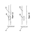
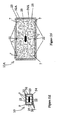
- Figures 1A - 1C schematically illustrate the gastrointestinal tract of a stomach 8, as follows:
- colon 16 An important feature of colon 16 is its semilunar folds 19, which provide it with a periodic structure, and which may be observed visually and by structural imaging such as ultrasound or MRI.
- Colon 16 leads to a rectum 12 and to an external anal sphincter muscle 18, through which matter is eliminated from the body.
- the diameter of colon 16 is about 2.5 times greater than the diameter of small intestine 14.
- an ingestible pill sized to navigate its way along small intestine 14 and image its walls will be too small to properly image the walls of colon 16.
- Figure 1C illustrates variations in the position of junction 11 and appendix 17, within stomach 8, due both to peristaltic and to differences among individuals. As seen from Figure 1C , it is not possible to define a fixed location within stomach 8 for junction 11, in relations to a fixed reference system of the body, for example, a pelvic bone 6. ( Figure 1C ).
- Table 1 [ Encyclopedia of Controlled Drug Delivery, volume 2, edited by Edith Mathiowitz ] summarizes parameters of the gastrointestinal route, as relating to liquid secretion and pH values.
- colon targeting may be based on pH value, since only in the colon the pH level is greater than 7. Other points worth noting are that the time an ingestible pill spends in the colon is considerable longer than that spent in any other portion of the gastrointestinal tract, yet the area to be imaged is orders of magnitude smaller than that of the small intestine. Additionally, secretion of gastrointestinal fluids in the colon is rather low.
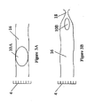
- Figures 2A - 2B schematically illustrate an ingestible pill 10, navigating its way along small intestine 14 ( Figure 2A ) and along colon 16 ( Figure 2B ).
- a scale 4 schematically illustrates the difference in diameters between small intestine 14 and colon 16.
- ingestible pill 10 is sized to navigate its way through and image the walls of small intestine 14, and thus makes good contact with the walls of small intestine 14.
- ingestible pill 10 is too small and too far from the colon walls, to image them properly.
- Figures 3A - 3B schematically illustrate an ideal situation, in which ingestible pill 10 expands in colon 16, to form expanded structure 10A ( Figure 3A ), sized for good contact with the walls of colon 16, but contracts again to contracted ingestible pill 10B ( Figure 3B ), on approaching external anal sphincter muscle 18, for elimination, in accordance with the present invention.
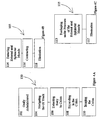
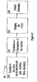
- Figures 4A - 4C schematically illustrate, in flowchart forms, operational steps, using ingestible pills, according to the present invention
- a method 100 for imaging includes the following steps:
- a method 105 for elimination includes the following steps:
- a method 105 for elimination includes the following steps:
- a method 115 for elimination includes the following steps:
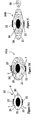
- Figures 5A - 5U schematically illustrate constructions of ingestible pills 10, adapted for expansion and possibly also contraction, in accordance with the present invention.
- FIGs 5A - 5C illustrate a first embodiment of the present invention.
- ingestible pill 10 in its contracted form ( Figure 5A ), has a volume 9, formed by a skin 21 and adapted for swallowing and for traveling within the gastrointestinal tract.
- Ingestible pill 10 further includes a core 20, containing the necessary electronic components, and one, two, or more detecting and (or) imaging probes 22, in an external region 7 near skin 21.
- detecting relates to performing instantaneous sensing, which may provide a "Yes” or “No” answer to the question, "Is there a suspicious finding?"
- Imaging relates to constructing an image in a space, which may be one- two- or three- dimensional. Where desired, instantaneous images may be stored as functions of time to further construct a "movie.”
- detecting is performed first, for example, as part of screening or regular checkup procedures, and imaging is performed as a follow-up, when the detection results call for it.
- Probes 22 may be connected to core 20 via cables 25, which are preferably wound or coiled, to allow for expansion. Additionally, skin 21 is preferably formed of an expansible material such as natural or synthetic rubber, or the like.
- a space between core 20 and skin 21 includes two materials 26 and 28, separated by a diaphragm 23 having an electronically controlled valve 24.
- Probes 22 and core 20 are adapted to provide an electronic signal, upon entering the colon, as will be described hereinbelow, in conjunction with Figures 6A - 6B and 7A . Additionally, valve 24 is designed to open, responsive to the electronic signal, allowing materials 26 and 28 to mix or react.
- ingestible pill 10 has a length dimension L1 of about 30 mm and a width dimension D1 of about 15 mm.
- the expansion is by a factor of between 3 and 4.
- expanded structure 10A has a length dimension L2 of about 90 - 120 mm and a width dimension D2 of about 45 - 60 mm. It will be appreciated that other factors of expansion and other dimensions, both larger and smaller, are similarly possible, and are within the scope of the present invention. It will be further appreciated that for veterinary uses, different dimensions will be employed, applicable for a particular animal.
- Figures 5A - 5C illustrates an expanded structure 10A which may be squashed by the pressure of external anal sphincter muscle 18, into a longer and narrower shape 10B, for elimination, as illustrated in Figure 4C , hereinabove.
- FIGS 5D - 5F illustrate a second embodiment of the present invention.
- ingestible pill 10 in its contracted form ( Figure 5D ), includes volume 9, formed by skin 21 and adapted for swallowing and for traveling within the gastrointestinal tract.
- Ingestible pill 10 further includes core 20, containing the necessary electronic components, and one, two, or more detecting and (or) imaging probes 22, in external region 7 near skin 21. Probes 22 are connected to core 20 via cables 25.
- the space between core 20 and skin 21 contains a material 32, adapted for expansion by osmosis, upon absorption of gastrointestinal fluids.
- Material 32 may be for example, a polyacrylic acid in a powder or cake form, a hydrogel, or guar gum.
- hydroxypropylmethylcellulose-HPMC or Polyox which expand when in contact with water
- Laminaria digitata or Laminaria japonica made from the root of a seaweed.
- SUPERABSORBNET a powder that absorbs liquids and with the right mix with Gels Amilans can be form a sponge, or other super absorbent polymers, such as AQUA KEEP, may be used.
- a first electronically controlled valve 34 being a one-way valve, allowing inflow only, is designed to open upon reaching the colon, as will be described hereinbelow, in conjunction with Figures 6A - 6B and 7A .
- gastrointestinal fluids flow in, and material 32 expands by osmosis into a material 38, bringing imagers 32 closer to the colon walls.
- a second electronically controlled valve 36 is designed to open on approaching external anal sphincter muscle 18, in preparation for elimination, as illustrated in Figure 4B , hereinabove, and as is further described hereinbelow, in conjunction with Figures 6A - 6B and 7C .
- material 38 issues out of the ingestible pill, allowing it to return to a contracted form 10B.
- second electronically controlled valve 36 is not used. Rather skin 21 may include one or more weak points 37, which may break or puncture under pressure allowing some of material 38 to issue out of the ingestible pill under the pressure of external anal sphincter muscle 18.
- skin 21 is formed of a material, which deteriorates after about 20 - 25 hours in the colon environment, as a safety feature. Thus, if after 25 hours, expanded structure 10A has not been eliminated, skin 21 will deteriorate, allowing material 38 to escape by outward diffusion.
- FIGS 5G - 5I illustrate a third embodiment of the present invention.
- ingestible pill 10 in its contracted form ( Figure 5G ), includes volume 9, formed by skin 21 and adapted for swallowing and for traveling within the gastrointestinal tract.
- Ingestible pill 10 further includes core 20, containing the necessary electronic components, and one, two, or more detecting and (or) imaging probes 22, in external region 7 near skin 21. Probes 22 are connected to core 20 via cables 25.
- the space between core 20 and skin 21 contains material 32, adapted for expansion, for example, by osmosis, upon absorption of water or gastrointestinal fluids.
- Material 32 may be, for example, polyacrylic acid in a powder or cake form.
- a material which may absorb water or gastrointestinal fluids and exapand may be used, for example, a hydrogel, guar gum, hydroxypropylmethylcellulose-HPMC, Polyox, Laminaria digitata, or Laminaria japonica.
- ingestible pill 10 includes a passive valve 40, formed of a material which dissolves in an environment of pH greater than 7, such as the colon environment.
- passive valve 40 is designed to dissolve in the colon, and material 32 expands by osmosis to material 38, causing ingestible pill 10 to expand to expanded structure 10A.
- Figure 5I illustrates natural elimination of squashed form 10B, since the hydrogel may be soft and pliable enough to yield under the pressure of external anal sphincter muscle 18. Additionally some material 38 may issue out since ingestible pill 10B has an open end, where dissolved plug 40 was.
- FIGS 5J - 5L illustrate a fourth embodiment of the present invention.
- ingestible pill 10 in its contracted form ( Figure 5J ), includes volume 9, formed by skin 21 and adapted for swallowing and for traveling within the gastrointestinal tract.
- Ingestible pill 10 further includes core 20, containing the necessary electronic components, and one, two, or more detecting and (or) imaging probes 22, in external region 7 near skin 21. Probes 22 are connected to core 20 via cables 25.
- Figures 5J and 5L illustrate a stent-like device 42 in its contracted state
- Figure 5K illustrates deployed state 44.
- Motor controlled expansion and contraction may be similar, for example, to the expansion and contraction of a car Jack, by the rotation of a controlling handle.
- Figures 5M - 5N illustrate a fifth embodiment of the present invention, wherein expansion takes place by two mechanisms.
- ingestible pill 10 in its contracted form ( Figure 5M ) includes volume 9, formed by skin 21 and adapted for swallowing and for traveling within the gastrointestinal tract.
- Ingestible pill 10 further includes core 20, containing the necessary electronic components, and one, two, or more detecting and (or) imaging probes 22, in external region 7 near skin 21. Probes 22 are connected to core 20 via cables 25.
- Ingestible pill 10 is formed of a first material 52, adapted for osmosis expansion to form first expanded material 52A, ( Figure 5N ).
- First material 52 is enclosed within a second material 54, adapted for expansion by water absorption to form expanded second material 54A.
- First material 52 may be a powder or a cake, for example, of polyacrylic acid.
- Second material 54 may be a pressed polymeric foam, such as a sponge, which expands as it fills with gastrointestinal fluids, upon exposure to them, while allowing gastrointestinal fluids to pass through it.
- expanded second material 54A is adapted to enclose and contain first expanded material 52A, and provide it with a shape.
- a guar gum or a hydrogel, which absorb water, may be used, for second material 54.
- Skin 21 is designed to dissolve in the colon, for example, by enzymes or by a chemical reaction unique to the colon environment, allowing gastrointestinal fluids to reach first and second materials 52 and 54.
- expanded structure 10A is soft and pliable, having a consistency similar to a stool, allowing it to be naturally eliminated.
- Figures 5O - 5Q illustrate a sixth embodiment of the present invention.
- ingestible pill 10 in its contracted form ( Figure 5O ) includes volume 9, formed by skin 21 and adapted for swallowing and for traveling within the gastrointestinal tract.
- Ingestible pill 10 further includes core 20, containing the necessary electronic components, and one, two, or more detecting and (or) imaging probes 22, in external region 7 near skin 21. Probes 22 are connected to core 20 via cables 25.
- Core 20 contains a pressurized or a liquefied gas balloon 55, for example, of CO 2 , having an electronically controlled valve 53, which is in communication with a plurality of inflatable loops 56, adapted to expand to inflated loops 56A, for example, via inlet hoses 57.
- Each expanded loop 56A has a length dimension of about L2 and a width dimension, which is about half D2. The loops may issue from all sides of core 20, so as to form expanded structure 56A.
- Probes 22 and core 20 are adapted to provide an electronic signal upon entering the colon, as will be described hereinbelow, in conjunction with Figures 6A - 6B and 7A .
- Electronically controlled valve 53 is designed to open, responsive to the electronic signal.
- skin 21 may be formed as a coating, which is adapted to withstand the acidic environment of the stomach and small intestine, and which is designed to dissolve in the colon, for example, by enzymes or by a chemical reaction unique to the colon environment.
- skin 21 may be an stretchable layer, for example, of rubber, that expands with loops 56A and contains them therein.
- Loops 56A are pliable and may be easily deformed for elimination.
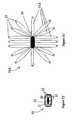
- Figures 5R - 5S illustrate a seventh embodiment of the present invention.
- ingestible pill 10 in its contracted form ( Figure 5R ) includes volume 9, formed by skin 21 and adapted for swallowing and for traveling within the gastrointestinal tract.
- Ingestible pill 10 further includes core 20, containing the necessary electronic components, and one, two, or more detecting and (or) imaging probes 22, in external region 7 near skin 21. Probes 22 are connected to core 20 via cables 25.
- ingestible pill 10 expands to form a star-fish-like expanded structure 10A.
- Star-fish-like expanded structure 10A may be inflatable, similar for example to the embodiment of Figures 5O - 5Q , inflated by a gas balloon.
- Star-fish-like expanded structure 10A may be a pressed foam, similar, to material 54 of Figures 5M - 5N , and adapted to expand by water absorption.
- Skin 21 may be a coating, adapted to withstand the acidic environment of the stomach and small intestine, yet designed to dissolve in the colon, for example, by enzymes or by a chemical reaction unique to the colon environment.
- skin 21 may be stretched with it.
- FIGS 5T - 5U illustrate an eighth embodiment of the present invention.
- ingestible pill 10 in its contracted form ( Figure 5T ) includes volume 9, formed by skin 21 and adapted for swallowing and for traveling within the gastrointestinal tract.
- Ingestible pill 10 further includes core 20, containing the necessary electronic components, and one, two, or more detecting and (or) imaging probes 22, in external region 7 near skin 21. Probes 22 are connected to core 20 via. cables 25.
- ingestible pill 10 expands to form a sea-urchin-like expanded structure 10A, having a plurality of flexible spines 55A.
- Sea-urchin-like expanded structure 10A may be inflatable, similar, for example, to the embodiment of Figures 5O - 5Q , so as to be inflated by a gas balloon.
- sea-urchin-like expanded structure 10A may be a pressed foam, similar, to material 54 of Figures 5M - 5N , and adapted to expand by water absorption.
- Skin 21 may be a coating, adapted to withstand the acidic environment of the stomach and small intestine, yet designed to dissolve in the colon, for example, by enzymes or by a chemical reaction unique to the colon environment.
- Figures 6A - 6C schematically illustrate several methods for controlling the expansion and contraction of ingestible pill 10, in accordance with the present invention.
- FIG 6A schematically illustrates an autonomous method 120, as follows:
- Figure 6B schematically illustrates an extracorporeally controlled method 140, as follows:
- Figure 6C schematically illustrates a passive method 160, as follows:
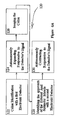
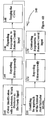
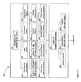
- Figures 7A - 7C schematically illustrates a summary flowchart 200 of methods for colon identification, ingestible-pill expansion control, ingestible-pill expansion, ingestible-pill imaging, ingestible-pill contraction control, ingestible pill contraction or squashing, and ingestible-pill elimination, in accordance with the present invention. Accordingly,
- the ingestible pill in accordance with the present invention, may be used as a mere detection tool, for first identification of pathologies, wherein after detection of a suspected pathology by the ingestible pill, a second apparatus, for example, a colonoscope equipped with a gamma probe may be used for extensive imaging.
- a second apparatus for example, a colonoscope equipped with a gamma probe may be used for extensive imaging.
- the ingestible pill in accordance with the present invention, may be used as an imaging apparatus.
- the imaging and (or) detection techniques of the present invention may be as described in commonly owned US Patent Application 20030139661, to Kimchy et al. , entitled, "Ingestible pill,” and which describes an ingestible device, adapted to travel in the gastrointestinal tract and perform a diagnostic image of tissue therein.
- the diagnostic image may comprise diagnostic information as a function of time, or diagnostic information as a function of distance traveled within the gastrointestinal tract.
- the ingestible device may be arranged to perform a diagnostic image of nuclear radiation of a radiophamaceut ⁇ cal, scintillation of a scintillation liquid, responsive to nuclear radiation of a radiophamaceutical, optical fluorescence of a fluorescing-pharmaceutical or of bare gastrointestinal-tract tissue, infrared radiation of the gastrointestinal-tract tissue, temperature-differences along the gastrointestinal-tract, impedance, ultrasound reflection, magnetic resonance, and a combination thereof.
- the ingestible device may be adapted for general screening of a large population, on the one hand, and for specific diagnoses of suspected pathologies, on the other.
- the imaging and (or) detection techniques of the present invention may be as described in commonly owned US Patent Application 20040054278, to Kimchy, et al. , entitled “Ingestible device,” and which relates to an ingestible pill, adapted to travel in the gastrointestinal tract and perform a diagnostic image of tissue therein.
- the diagnostic image may comprise diagnostic information as a function of time, or diagnostic information as a function of distance traveled within the gastrointestinal tract.
- An imaging method by depth calculations is provided, based on the attenuation of photons of different energies, which are emitted from the same source, coupled with position monitoring.
- imaging and (or) detection techniques may be as follows:
- Gamma imaging and (or) detection may be performed, for example, using radiopharmaceuticals such as monoclonal antibodies, such as CEA Scan (arcitumomab), made by Immunomedics Inc., or other agents, e.g., fibrinogen or fluorodeoxyglucose, tagged with a radioactive isotope, e.g., 99M technetium, 67 gallium, 201 thallium, 111 indium, 123 iodine, 125 iodine and 18 fluorine, which may be administered orally, intravenously, or even rectally.
- radiopharmaceuticals such as monoclonal antibodies, such as CEA Scan (arcitumomab), made by Immunomedics Inc.
- agents e.g., fibrinogen or fluorodeoxyglucose
- a radioactive isotope e.g., 99M technetium, 67 gallium, 201 thallium, 111 in
- the gamma imager, or radioactive-emission probe may be constructed of room temperature CdZnTe, obtained, for example, from eV Products, a division of II-VI Corporation, Saxonburg Pa., 16056.
- CdZnTe room temperature
- another solid-state detector such as CdTe, HgI, Si, Ge, or the like, or a scintillation detector, such as NaI(Tl), LSO, GSO, CsI, CaF, or the like, or another detector as known, may be used.
- the radioactive-emission probe may be a single-pixel or a multi-pixel probe. Preferably, each pixel is about 3 mm X 3 mm in size.
- radioactive-emission probes as known, may be used.
- the radioactive-emission probe may be constructed as taught by U.S. Patent 4,782,840 to Martin, Jr., et al. , entitled, "Method for locating, differentiating, and removing neoplasms," or as taught by other works, which illustrate radioimmunoguided surgery, or RIGS TM .
- RIOS is a registered trademark of Neoprobe Corporation of Dublin, Ohio.
- radioactive-emission probe may be constructed as taught by U.S. Patent 4,841,803 to Denen, et al. , entitled, "Detector and localizer for low energy radiation emissions,” and which describes a probe particularly suited for use in immuno-guided surgery capable of detecting very faint gamma emissions and thereby localizing cancerous tumor. Detection is achieved under room temperature conditions using a crystal such as cadmium telluride. To achieve the extreme sensitivity capabilities of the apparatus, an instrumentation approach has been developed in which the somewhat fragile crystal is securely retained in isolation from externally induced incidents otherwise creating excessive noise. Microphonic effects are minimized through employment of a sequence of materials exhibiting divergent acoustic impedance. Capacitive effects caused by minute intercomponent movements are controlled to acceptable levels.
- a preamplifier is incorporated within the probe itself, which employs an integrator stage front end combining a field effect transistor and bipolar device with a very small feedback capacitance of less than one picofarad.
- a bootstrap technique is utilized to enhance the amplification of the bipolar amplification stage. Pulse related signals outputted from the device are normalized and compared to produce pulse data, which are analyzed. In one mode of operation a siren effect is employed to guide the surgeon towards emission sources.
- the aforementioned probe is directed at low energy radionucleides, such as I 125 . Additionally, the distribution of radiolabeled antibody with the nuclide is quite sparse so that background emissions can be minimized and the ratio of tumor-specific counts received to background counts can be maximized,
- the probe instrument and related control circuitry has been assigned the trade designation "NEOPROBE" instrument.
- radioactive-emission probe may be constructed as taught by U.S. Patent 5,151,598 , or 5,070,878 , or 4,893,013, all to Denen , and all entitled, "Detector and localizer for low energy radiation emissions.”
- radioactive-emission probe may be constructed as taught by U.S. Patent 6,259,095, to Boutun, et al. , entitled, "System and apparatus for detecting and locating sources of radiation.”
- Optical-fluorescence-spectroscopy imaging and (or) detection may be performed, for example, using fluorescence pharmaceuticals.
- fluorescence pharmaceuticals For example, ematoporphyrin derivatives (HPD), give a well-structured fluorescence spectrum, when excited in the Soret band around 405 nm. The fluorescence spectrum shows typical peaks at about 630 and 690 nm, superimposed in practice on more unstructured tissue autofluorescence.
- DHE dihematoporphyrin ether/ester
- HP hematoporphyrin
- PHE polyhematoporphyrin ester
- TSPC tetrasulfonated phthalocyanine
- the optical fluorescence probe may be constructed as taught by U.S. Patent 5,115,137, to Andersson-Engels, et al , entitled, "Diagnosis by means of fluorescent light emission from tissue," and which relates to improved detection of properties of tissue by means of induced fluorescence of large molecules.
- the tissue diameter may then be evaluated from the observed large-molecule spectra.
- U.S. Patent 5,115,137 the spectrum for tonsil cancer is clearly different from normal mucosa, due to endogenous porphyrins.
- the optical fluorescence probe may be constructed as taught by U.S. Patent 4,785,806, to Deckelbaum , entitled, "Laser ablation process and apparatus,” and which describes a process and apparatus for ablating atherosclerotic or neoplastic tissues.
- Optical fibers direct low power light energy at a section of tissue to be ablated to cause the section to fluoresce.
- the fluorescence pattern is analyzed to determine whether the fluorescence frequency spectrum is representative of normal or abnormal tissue.
- a source of high power, ultraviolet, laser energy directed through an optical fiber at the section of tissue is fired only when the fluorometric analysis indicates that it is directed at abnormal tissue.
- the optical fluorescence probe may be constructed as taught by U.S. Patent 4,682,594, to Mok , entitled, "Probe-and fire lasers," and which describes a method and apparatus of irradiating a treatment area within a body, such as blood vessel plaque.
- the optical fluorescence probe may be constructed as taught by U.S. Patent 4,336,809 to Clark , entitled, "Human and animal tissue photoradiation system and method," It relates to utilizing certain dyes, which not only selectively stain neoplastic tissue but also fluoresce in response to irradiation. Additionally, they are photodynamically cytotoxic in response to a proper wavelength of light in the presence of oxygen within living tissue.
- One of the dyes that is presently preferred for these characteristics contains hematoporphyrin or hematoporphyrin derivatives that when administered intravenously remain at higher concentrations for longer periods of time in traumatized or malignant tumorous tissue than in normal tissue.
- This dye also has a strong absorption peak centered at a wavelength of approximately 407 nanometers and responds to excitation at about this wavelength by fluorescing at a wavelength of about 614 nanometers.
- This same dye has a photodynamic absorption peak at a wavelength of about 631 nanometers and is cytotoxic to malignant tissue containing the dye when irradiated with red light of about this wavelength.
- krypton ion laser was used for its 406.7/413.1 nanometer lines matching the 407 nanometer absorption peak of hematoporphyrin.
- the optical fluorescence probe may be constructed as taught by U.S. Patent 6,258,576, to Richards-Kortum, et al. , entitled, "Diagnostic method and apparatus for cervical squamous intraepithelial lesions in vitro and in vivo using fluorescence spectroscopy," and which relates to the use of multiple illumination wavelengths in fluorescence spectroscopy for the diagnosis of cervical cancer and precancer.
- SILs squamous intraepithelial lesions
- the detection may be performed in vitro or in vivo. Multivariate statistical analysis has been employed to reduce the number of fluorescence excitation-emission wavelength pairs needed to re-develop algorithms that demonstrate a minimum decrease in classification accuracy.
- the ultrasound probe for imaging and (or) detection may be constructed, for example, as taught by U.S. Patent Application 20010020131, to Kawagishi, Tetsuya, et al. , entitled, "Ultrasonic diagnosis system,” which describes an ultrasonic diagnosis apparatus that has an ultrasonic probe, having a plurality of arrayed transducer elements, a transmitting beam former for generating driving signals for driving transducer elements, and a receiving beam former for generating receiving signals based on echo signals received by transducer elements.
- the transmitting beam former generates driving signals so that phases of ultrasonic waves generated from transducer elements are aligned at multiple focal points
- An image processor extracts harmonic components from receiving signals of ultrasonic waves having multiple focal points, and generates ultrasonic image data based on the harmonic components.
- the ultrasound imager may be constructed, for example, as taught by, U.S. Patent 5,284,147, to Hanoaka, et al. , entitled, "Ultrasonic probe to be installed on fingertip,” which relates to an ultrasonic probe to be inserted into the body of a subject for image-processing a diagnostic target thereof by ultrasonic waves transmitted to and received from the inside of the body.
- Contrast agents may be used in conjunction with ultrasound imaging, for example as taught by U.S. Patent 6,280,704, to Schutt, et al. , entitled, "ultrasonic imaging system utilizing a long-persistence contrast agent,".
- the MRI probe for imaging and (or) detection may be constructed, for example, as taught by U.S. Patent 5,572,132, to Pulyer, et al. , entitled, "MRI probe for external imaging," wherein an MRI catheter for endoscopical imaging of tissue of the artery wall, rectum, urinal tract, intestine, esophagus, nasal passages, vagina and other biomedical applications is described.
- the invention teaches an MRI spectroscopic probe having an external background magnetic field B 0 (as opposed to the internal background magnetic filed of the large horizontal bore superconducting magnet.)
- the probe comprises (i) a miniature primary magnet having a longitudinal axis and an external surface extending in the axial direction and (ii) a RF coil surrounding and proximal to said surface.
- the primary magnet is structured and configured to provide a symmetrical, preferably cylindrically shaped, homogeneous field region external to the surface of the magnet.
- the RF coil receives NMR signals from excited nuclei.
- one or more gradient coils are provided to spatially encode the nuclear spins of nuclei excited by an RF coil, which may be the same coil used for receiving NMR signals or another RF coil.
- contrast agents such as, which are preferably tied to antibodies, such as may be used.
- the video camera may be constructed, for example, as taught by U.S. 5,604,531, to Iddan, et al. , entitled, "In vivo video camera system,” describes a video camera system, encapsulated within an ingestible pill, arranged to pass through the entire digestive tract, operating as an autonomous video endoscope.
- the ingestible pill includes a camera system and an optical system for imaging an area of interest onto the camera system, and a transmitter, which relays the video output of the camera system to an extracorporeal reception system.
- a light source is located within a borehole of the optical system.
- the light source may be visible light or infrared light.
- the video camera may be constructed, for example, as taught by U.S. Patent Application 20010035902, to Iddan, G. J., et al. , entitled, "Device and system for in vivo imaging,” and which describes a system and method for obtaining in vivo images.
- the system contains an imaging system and an ultra low power radio frequency transmitter for transmitting signals from the CMOS imaging camera to a receiving system located outside a patient.
- the imaging system includes at least one CMOS imaging camera, at least one illumination source for illuminating an in vivo site and an optical system for imaging the in vivo site onto the CMOS imaging camera.
- the temperature sensor for imaging and (or) detection may be constructed, as an infrared thermography imager, taught by Harzbecker K, et al., "Thermographic thorax diagnostics,” Z Intele Inn Med. 1978 Feb 1;33(3):78-80 , and by Dexter LI, Kondrat'ev VB., "Thermography in differential diagnosis of lymphostasis in the lower limbs," Vestn Khir Im I I Crrek. 1976 Jun; 116(6):60-4 .
- An Impedance probe for imaging and (or) detection may be constructed, for example, as taught by U.S. Patents 6,308,097 , 6,055,452 and 5,810,742, to Pearlman, A. L. , entitled, "Tissue characterization based on impedance images and on impedance measurements," Alternatively, it may be constructed as taught by U.S. Patent 4,458,694, to Sollish, et al. , entitled, "Apparatus and method for detection of tumors in tissue,".
- the impedance imager may include a probe, comprising a plurality of elements, means for applying an AC signal to the tissue, means for sensing electrical properties at each of the probe elements at different times, and signal processing circuitry, coupled to the sensing means, for comparing the electrical properties sensed at the different times.
- the impedance imager may thus provide an output of the dielectric constants of localized regions of tissue.
- the present invention is applicable to humans and animals, taking into account the digestive system anatomy of each animal.
Description
- The present invention relates to an ingestible pill platform for colon imaging, and more particularly, to an ingestible pill platform, designed to recognize its entry to the colon and designed to expand in the colon, for improved imaging of the colon walls.
- The impact of cancer of the gastrointestinal tract is grave. In spite of enormous expenditures of financial and human resources, early detection of malignant tumors remains an unfulfilled medical goal. While it is known that a number of cancers are treatable if detected at an early stage, lack of reliable screening procedures results in their being undetected and untreated.
- There are other gastrointestinal-tract disorders, which similarly require reliable screening and diagnostic procedures for early detection and treatment. These include, for example, irritable bowel syndrome, fluxional diarrhea, ulcerative colitis, collagenous colitis, microscopic colitis, lymphocytic colitis, inflammatory bowel disease, Crohn's disease, infectious diarrhea, ulcerative bowel disease, lactase deficiency, infectious diarrhea, amebiasis, and giardiasis.
- A large number of techniques are available today for tissue characterization, for example, to determine the presence of abnormal tissue, such as cancerous or pre-cancerous tissue. Many of these may be used with miniature probes that may be inserted into a body lumen.
- Tissue Characterization by Nuclear Imaging: Nuclear-radiation imaging of radionuclide-labeled antibodies (Gamma Imaging): The use of radiolabeled immunoglobulin for tumor localization, by functional imaging, was shown to be possible in 1959 when Day et al. radiolabeled isolated antifibrin. (Day, E. O.; Planisek, J. A.; Pressman D: "Localization of Radioiodinated Rat Fibrinogen in Transplanted Rat Tumors", J. Natl. Cancer Inst. 23: 799-812, 1959). Since the work of Day et al, in 1959, an expanding number of monoclonal antibodies have received FDA approval. Examples, applicable to gastrointestinal tract tumors, include the following:
- 1. CEA-Scan is a Tc99m-labeled monoclonal antibody fragment, which targets CEA - produced and shed by colorectal carcinoma cells. The use of anti-CEA monoclonal antibody has been recommended as the only marker to estimate prognosis and response to therapy. Anti-CEA monoclonal antibody may also be labeled by other radioisotopes, for example, iodine isotopes. (Jessup JM. 1998, Tumor markers - prognostic and therapeutic implications for colorectal carcinoma, Surgical Oncology; 7: 39-151.)
- 2. In111-Satumomab Pendetide (Oncoscint®) is designed to target TAG-72. TAG-72 is a mucin-like glycoprotein expressed in human colorectal, gastric, ovarian, breast and lung cancers. It is rarely expressed in normal human adult tissues. (Molinolo A; Simpson JF; et al. 1990, Enhanced tumor binding using immunohistochemical analyses by second generation anti-tumor-associated glycoprotein 72 monoclonal antibodies versus monoclonal antibody B72.3 in human tissue, Cancer Res. 50(4): 1291-8.)
- 3. Lipid-Associated Sialic Acid (LASA) is a tumor antigen, which for colorectal carcinoma LASA, has a similar sensitivity as CEA but a greater specificity for differentiating between benign and malignant lesions. (Ebril KM, Jones JD, Klee GG. 1985, Use and limitations of serum total and lipid-bound sialic acid concentrations as markers for colorectal cancer, Cancer; 55:404-409.)
- 4. Matrix Metaloproteinase-7 (MMP-7) is a proteins enzyme, believed to be involved in tumor invasion and metastasis. Its expression is elevated in tumor tissue compared to normal tissue and may be a potential marker for tumor aggressiveness and traditional staging. (Mori M, Barnard GF et al. 1995, Overexpression of matrix metalloproteinase-7 mRNA in human colon carcinoma. Cancer; 75: 1516-1519.)
- Additionally, pharmaceuticals may be used as markers for nonmalignant pathologies, such as gastrointestinal inflammations and infections. Examples include the following:
- 1. Ga67 citrate binds to transferrin and is used for detection of chronic inflammation. (Mettler FA, and Guiberteau MJ, Eds. 1998, Inflammation and infection imaging. Essentials of nuclear medicine. Fourth edition. Pgs: 387-403.)
- 2. Nonspecific-polyclonal immunoglobulin G (IgG) may be labeled with both In111 or Tc99m, and has a potential to localize nonbacterial infections. (Mettler FA, and Guiberteau MJ, ibid.)
- 3. Radio-labeled leukocytes, such as such as In111 oxine leukocytes and Tc99m HMPAO leukocytes are attracted to sites of inflammation, where they are activated by local chemotactic factors and pass through the endothelium into the soft tissue. Labeled leukocytes in the gastrointestinal tract are nonspecific and may indicate a number of pathologies, including Crohn's disease, ulcerative colitis, psudomembranous colitis, diverticulosis, various gastrointestinal infections, fistulas, ischemic or infracted bowel. (Mettler FA, and Guiberteau MJ, ibid; Corstens FH; van der Meer JW, 1999. Nuclear medicine's role in infection and inflammation. Lancet; 354 (9180): 765-70.)
- The particular choice of a radionuclide for labeling antibodies is dependent upon its nuclear properties, the physical half-life, the detection instruments' capabilities, the pharmacokinetics of the radiolabeled antibody, and the degree of difficulty of the labeling procedure. Examples of radionuclides used for labeling antibodies include Technetium Tc99m, Iodine I123, I123, I131, and I133, Indium In111, Gallium Ga67, thallium Tl201, fluorine F18 and P32,
- Nuclear-radiation imaging of radionuclide-labeled antibodies is a subject of continued development and study. Its advantage is that pathologies, which are embedded within a tissue or hidden by residue, may still be visible to the gamma camera, since the gamma rays penetrate the tissue or residue, In fact various means may be employed to calculate the depth of the pathology within the tissue, for example, based on the attenuation of photons of different energies, which are emitted from a same source, as taught by commonly owned
US Patent Applications 10/616,30710/616,301, both filed on July 10, 2003 PCT/IL03100917, filed on Nov. 4, 2003 - A particular difficulty in using radionuclides is that blood-pool background radioactivity has caused ordinary scintigrams to prove difficult to intorpret. Computer subtraction of radioactive blood-pool background radioactivity has been attempted to enhance imaging. Yet the ability to detect occult tumors has remained low,
- Attempts to overcome the blood-pool background radioactivity are described, for example, in
U.S. Patent 4,782,840 to Martin, Jr., et al. , entitled, "Method for locating, differentiating, and removing neoplasms,"U.S. Patent 4,801,803 to Denen, et al. , entitled, "Detector and localizer for low energy radiation emissions,"U.S. Patent 5,151,598 to Denen , entitled, "Detector and localizer for low energy radiation emissions,"U.S. Patent 4,893,013 to Denen et al. , entitled, "Detector and Localizer for Low Energy Radiation Emissions," andU.S. Patent 5,070,878 to Denen , entitled, "Detector and localizer for low energy radiation emissions," andU.S. Patent 6,259,095, to Boutun, et al. , entitled, "System and apparatus for detecting and locating sources of radiation," which relate to the RIGS™. (RIGS is a registered trademark of Neoprobe Corporation of Dublin, Ohio), and to "NEOPROBE" instrument. - In spite of these advances, background radiation remains an obstacle that limits the probe sensitivity to occult tumors, and there are continued endeavors to minimize its effect.
- Tissue Characterization by Ultrasonography: Ultrasonography is a medical imaging technique, using high frequency sound waves in the range of about 1 to 20 MHz and their echoes, The sound waves travel in the body and are reflected by interfaces between different types of tissues, such as between a healthy tissue and a denser cancerous tissue, or between a portion of a soft tissue and a bone. The ultrasound probe receives the reflected sound waves and the associated instrumentation calculates the distances frown the probe to the reflecting boundaries.
- The ultrasound probe includes a piezoelectric crystal, which produces an electric signal in response to a pressure pulse. The shape of the probe determines its field of view, and the frequency of the emitted sound determines the minimal detectable object size. Generally, the probes are designed to move across the surface of the body. However, some probes are designed to be inserted through body lumens, such as the vagina or the rectum, so as to get closer to the organ being examined.
- Before the early 1970's ultrasound imaging systems were able to record only the strong echoes arising from the outlines of an organ, but not the low-level echoes of the internal structure. In 1972 a refined imaging mode was introduced called gray-scale display, in which the internal texture of many organs became visible. In consequence, ultrasound imaging became a useful tool for imaging tumors, for example, in the liver.
- Contrast agents may be used in conjunction with ultrasound imaging, for example as taught by
U.S. Patent 6,280,704, to Schutt, et al. , entitled, "Ultrasonic imaging system utilizing a long-persistence contrast agent,". - Tissue Characterization by Electrical Impedance Imaging: Electrical impedance imaging relates to measuring the impedance between a point on the surface of the skin and some reference point on the body of a patient. Sometimes, a multi-element probe, formed as a sheet having an array of electrical contacts, is used for obtaining a two-dimensional impedance map of the tissue, for example, the breast. The two-dimensional impedance map may be used, possibly in conjunction with other data, such as mammography, for the detection of cancer.
- Rajshekhar, V. ("Continuous impedance monitoring during CT-guided stereotactic surgery: relative value in cystic and solid lesions," Rajshekhar, V., British Journal of Neurosurgery, 1992, 6, 439-444) describes using an impedance probe with a single electrode to measure the impedance characteristics of lesions. The objective of the study was to use the measurements made in the lesions to determine the extent of the lesions and to localize the lesions more accurately. The probe was guided to the tumor by CT and four measurements were made within the lesion as the probe passed through the lesion. A biopsy of the lesion was performed using the outer sheath of the probe as a guide to position, after the probe itself was withdrawn.
- Other work in impedance probes includes
U.S. Patent 4,458,694, to Sollish, et al. , entitled, "Apparatus and method for detection of tumors in tissue,"U.S. Patent 4,291,708 to Frei, et al. , entitled, "Apparatus and method for detection of tumors in tissue," andU.S. Patents 6,308,097 ,6,055,452 and5,810,742, to Pearlman, A, L ., entitled, "Tissue characterization based on impedance images and on impedance measurements,". - Tissue Characterization by Optical Fluorescence Spectroscopy: When a sample of large molecules is irradiated, for example, by laser light, it will absorb radiation, and various levels will be excited. Some of the excited states will return back substantially to the previous state, by elastic scattering, and some energy will be lost in internal conversion, collisions and other loss mechanisms. However, some excited states will create fluorescent radiation, which, due to the distribution of states, will give a characteristic wavelength distribution.
- Some tumor-marking agents give well-structured fluorescence spectra, when irradiated by laser light. In particular, hematoporphyrin derivatives (HPD), give a well-structured fluorescence spectrum, when excited in the Soret baud around 405 nm. The fluorescence spectrum shows typical peaks at about 630 and 690 nm, superimposed in practice on more unstructured tissue autofluorescence, Other useful tumor-marking agents are dihematoporphyrin ether/ester (DHE), hematoporphyrin (HP), polyhematoporphyrin ester (PHE), and tetrasulfonated phthalocyanine (TSPC), when irradiated at 337 nm (N2 laser).
-
U.S. Patent 5,115,137, to Andersson-Engels, et al , entitled, "Diagnosis by means of fluorescent light emission from tissue," relates to improved detection of properties of tissue by means of induced fluorescence of large molecules. The tissue character may then be evaluated from the observed large-molecule spectra. According toU.S. Patent 5,115,137 , the spectrum for tonsil cancer is clearly different from normal mucosa, due to endogenous porphyrins. -
U.S. Patent 6,258,576, to Richards-Kortum, et al. , entitled, "Diagnostic method and apparatus for cervical squamous intraepithdlial lesions in vitro and in vivo using fluorescence spectroscopy," relates to the use of multiple illumination wavelengths in fluorescence spectroscopy for the diagnosis of cancer and precancer, for example, in the cervix. In this manner, it has been possible to (i) differentiate normal or inflamed tissue from squamous intraepithelial lesions (SILs) and (ii) differentiate high grade SILs from non-high grade SILs. The detection may be performed in vitro or in vivo. Multivariate statistical analysis has been employed to reduce the number of fluorescence excitation-emission wavelength pairs needed to re-develop algorithms that demonstrate a minimum decrease in classification accuracy. For example, the method of the aforementioned patent may comprise illuminating a tissue sample with electromagnetic radiation wavelengths of about 337 nm, 380 nm and 460 nm, to produce fluorescence; detecting a plurality of discrete emission wavelengths from the fluorescence; and calculating from the emission wavelengths a probability that the tissue sample belongs in particular tissue classification. -
U.S. Patent Application 2003/01383786, to Hashimshony - Tissue Characterization by Optical Reflectance Spectroscopy: The application optical reflectance spectroscopy for tissue characterization is described, for example, in http://www.sbsp-limb.nichd.nih.gov/html/spectroscopy.html, downloaded on March 15, 2005, disclosing an optical reflectance spectroscopy (ORS) device for measuring the thickness of the epithelial layer, and an evaluation techniques based on oblique angle reflectance spectroscopy, that allows assessment of the scattering and absorption properties of the epithelium and stroma, thus providing information on chronic oral epithelial tissue inflammation, which is considered a potential diagnostic precursor to oral cancer.
- Additionally, Tomatis, A., et al, studied reflectance images of 43 pigmented lesions of the skin (18 melanomas, 17 common melanocytic naevi and eight dysplastic naevi). Reflectance images were acquired by a telespectrophotometric system and were analyzed in the spectral range from 420 to 1040 nm, to discriminate melanoma from benign melanocytic entities. Different evaluations were carried out considering the whole spectrum, the visible and the near infrared. A total of 33 (76.7%) lesions were correctly diagnosed by the telespectrophotometric system, compared with 35 (81.4%) correct clinical diagnoses. Reflectance in the infrared band appears diagnostically relevant.
- Tissue Characterization by Magnetic Resonance Imaging (MRI): Magnetic resonance imaging is based on the absorption and emission of energy in the radio frequency range of the electromagnetic spectrum, by nuclei having impaired spins.
- Conventional MRI is a large-apparatus, for whole body imaging, having:
- i. a primary magnet, which produces the Bo field for the imaging procedure;
- ii. gradient coils for producing a gradient in Bo;
- iii. an RF coil, for producing the B1 magnetic field, necessary to rotate the spins by 90° or 180° and for detecting the MRI signal; and
- iv. a computer, for controlling the components of the MRI imager.
- Generally, the magnet is a large horizontal bore superconducting magnet, which provides a homogeneous magnetic field in an internal region within the magnet. A patient or object to be imaged is usually positioned in the homogeneous field region located in the central air gap for imaging. A typical gradient coil system comprises an anti-Helmholtz type of coil. These are two parallel ring shaped coils, around the z axis. Current in each of the two coils flows in opposite directions creating a magnetic field gradient between the two coils,
- The RF coil creates a B1 field, which rotates the net magnetization in a pulse sequence. The RF coils may be: 1) transmit and receive coils, 2) receive only coils, and 3) transmit only coils.
- As described hereinabove, the MRI relies on a magnetic field in an internal region within the magnet. As such, it is unsuitable as a handheld probe or an endoscopic probe, because the tissue to be imaged has to be in the internal region of the image,
- However,
U.S. Patent 5,572,132, to Pulyer, et al. , entitled, "MRI probe for external imaging," describes an MRI spectroscopic probe having an external background anagnetic field B0 (as opposed to the internal background magnetic filed of the large horizontal bore superconducting magnet.). Thus, an MRI catheter for endoscopical imaging of tissue of the artery wall, rectum, urinal tract, intestine, esophagus, nasal passages, vagina and other biomedical applications may be constructed. The probe comprises (i) a miniature primary magnet having a longitudinal axis and an external surface extending in the axial direction, and (ii) a RF coil surrounding and proximal to said surface. The primary magnet is structured and configured to provide a symmetrical, preferably cylindrically shaped, homogeneous field region external to the surface of the magnet. The RF coil receives NMR signals from excited nuclei, For imaging, one or more gradient coils are provided to spatially encode the nuclear spins of nuclei excited by an RF coil, which may be the same coil used for receiving NMR signals or another RF coil. - Contrast agents may be used in conjunction with MRI, For example,
U.S. Patent 6,315,981 to Unger , entitled, "Gas filled microspheres as magnetic resonance imaging contrast agents," describes the use of gas filled microspheres as contrast agents for MRI. Unger further describes how gas can be used in combination with polymer compositions and possibly also with paramagnetic, superparamagnetic, and liquid fluorocarbon compounds as MRI contrast agents. It is further shown how the gas stabilized by polymers would function as an effective susceptibility contrast agent to decrease signal intensity on T2 weighted images; and that such systems are particularly effective for use as gastrointestinal MRI contrast media. Additionally, when MRI contrast agents are tied up to antibodies, the MRI may be used as a functional imaging technique. The MRI contrast agent may be a solution of Gd - dtpa, prepared for injection. - Tissue Characterization by Temperature Imaging: Temperature Imaging for locating and detecting neoplastic tissue has been known, since the 1950's, when it was discovered that the surface temperature of skin in the area of a malignant tumor exhibited a higher temperature than that expected of health tissue. Thus, by measuring body skin temperatures, it became possible to screen for the existence of abnormal body activity such as cancerous tumor growth. With the development of liquid crystals and methods of forming temperature responsive chemical substrates, contact thermometry became a reality along with its use in medical applications. Devices employing contact thermometry could sense and display temperature changes through indicators, which changed colors, either permanently or temporarily, when placed in direct physical contact with a surface such as skin, reflecting a temperature at or near the point of contact. An abnormal reading would alert a user to the need for closer, more detailed examination of the region in question. However, the art in this area has been directed primarily at sensing and displaying temperatures on exterior skin surfaces.
-
U.S. Patent 6,135,968, to Brounstein , entitled, "Differential temperature measuring device and method", describes a device and method for sensing temperatures at internal body locations non-surgically accessible only through body orifices. The device is particularly useful in medical applications such as screening for cancer and other abnormal biological activity signaled by an increase in temperature at a selected site. - Ingestible Pills: Ingestible radio pills, which are ingestible capsules containing a transmitter are known. In 1964 research at Heidelberg University developed a pill for monitoring pH of the gastrointestinal tract. (Noller, H. G., "The Heidelberg Capsule Used For the Diagnosis of Pepic Diseases", Aerospace Medicine, Feb., 1964, pp. 15-117.)
-
U.S. 5,604,531, to Iddan, et al. , entitled, "In vivo video camera system," describes a video camera system, encapsulated within an ingestible pill, arranged to pass through the entire digestive tract, operating as an autonomous video endoscope. The ingestible pill includes a camera system and an optical system for imaging an area of interest onto the camera system, and a transmitter, which relays the video output of the camera system to an extracorporeal reception system. A light source is located within a borehole of the optical system. - Similarly,
U.S. Patent Application 20010035902, to Iddan, G. J., et al. , entitled, "Device and system for in vivo imaging," describes a system and method for obtaining in vivo images. The system contains an imaging system and an ultra low power radio frequency transmitter for transmitting signals from the CMOS imaging camera to a receiving system located outside a patient. The imaging system includes at least one CMOS imaging camera, at least one illumination source for illuminating an in vivo site and an optical system for imaging the in vivo site onto the CMOS imaging camera. -
U.S. Patent 6,324,418, to Crowley, et al. , entitled, "Portable tissue spectroscopy apparatus and method," describes a portable tissue spectroscopy apparatus including at least one light source, at least one light detector, a power source and a controller module, all disposed inside a housing that is insertable inside a body. The housing may be in the form of a hand-holdable probe or in the form of a capsule that can be swallowed or implanted in the body. The probe further includes a display mounted at a proximal end of the housing for displaying tissue characteristics. The capsule further includes a transmitter mounted inside the capsule and a receiver placed outside the body for transmitting signals representative of tissue characteristics to a remote receiver. - The capsule includes one or more light emitters and one or more light detectors. The light detectors may be located in various places within the housing for detecting spectroscopic properties from various tissues near the capsule. The capsule may further include other types of emitters and sensors. The additional emitters and sensors, for example, can relate to electromagnetic radiation, pressure, temperature, x-ray radiation and/or heat. In one embodiment, the capsule further comprises an acoustic transmitter and a receiver for measuring flow of fluid or for detecting echo location of the capsule. In another embodiment, the capsule further includes diagnostic sensors such as monitoring electrodes, pressure sensors and temperature sensors.
- Methods of tracking ingestible devices, such as radio pills, are known.
U.S. Patent 5,279,607, to Schentag, et al. , entitled, "Telemetry capsule and process," andU.S. Patent 5,395,366, to D'Andrea et al. , entitled, "Sampling capsule and process," described hereinabove, include extracorporeal apparatus having a plurality of antennae, used to determine the geographic position of the capsule within the gastrointestinal tract. For example, at least three antennae, located at different distances from the point source, and dedicated algorithms may be used to determine the precise location of the capsule, at any time. -
U.S. Patent 6,082,365 to Andrii et al. , entitled, "Method and arrangement for determining the position of a marker in an organic cavity," describe a method for pinpointing a marker such as an ingestible capsule. The method requires that the patient be positioned within a magnetic field, for example, as used for MRI imaging. - Commonly owned
US Patent Application 20030139661, to Kimchy et al. , entitled, "Ingestible pill," describes an ingestible device, adapted to travel in the gastrointestinal tract and perform a diagnostic image of tissue therein. The diagnostic image may comprise diagnostic information as a function of time, or diagnostic information as a function of distance traveled within the gastrointestinal tract. Specifically, the ingestible device may be arranged to perform a diagnostic image of nuclear radiation of a radiophamaceutical, scintillation of a scintillation liquid, responsive to nuclear radiation of a radiophamaceutical, optical fluorescence of a fluorescing-pharmaceutical or of bare gastrointestinal-tract tissue, infrared radiation of the gastrointestinal tract tissue, temperature-differences along the gastrointestinal-tract, impedance, ultrasound reflection, magnetic resonance, and a combination thereof. The ingestible device may be adapted for general screening of a large population, on the one hand, and for specific diagnoses of suspected pathologies, on the other. - Additionally, commonly owned
US Patent Application 20040054278, to Kimchy, et al. , entitled "Ingestible device," describes a device, adapted to travel in the gastrointestinal tract and perform a diagnostic image of tissue therein. The diagnostic image may comprise diagnostic information as a function of time, or diagnostic information as a function of distance traveled within the gastrointestinal tract. An imaging method by depth calculations is provided, based on the attenuation of photons of different energies, which are emitted from the same source, coupled with position monitoring. -
US 2003/0020810 to Takizawa et al. teaches a capsule including battery, an imaging device and an illumination device. The capsule may further comprise a pH sensor for detecting whether or not the capsule reaches a body part to be examined. -
US 2002/0198470 to Imran et al. teaches a device and method for mapping, diagnosing and treating the intestinal tract using a capsule passing through the intestinal tract. In one embodiment, an externally transmitted telemetric signal causes a balloon plasty capsule to deploy an expandable member that dilates the intestinal passage. -
WO 2004/028335 by Iddan teaches an in-vivo sensing system incorporating a sensing device movably disposed within a housing such that the orientation of the sensing device may be moved or changed in response to substantially small forces. The in-vivo sensing device may be ingested and may naturally traverse a lumen such as the GI tract or may be anchored at a surgical site. -
US 2002/0099310 to Kimchey et al. describes a method for detecting a site of interest in a gastrointestinal tract, wherein the method includes sensing a length traveled by a sensor in a gastrointestinal tract from a reference point to a site of interest in the gastrointestinal tract. - Notwithstanding the high level of sophistication of the aforementioned systems, gastrointestinal pathologies, and particularly, occult tumors have remained elusive in medical diagnosis. There is thus a widely recognized need for, and it would be highly advantageous to have, a device and method for detecting pathologies in the gastrointestinal tract devoid of the above limitations.
- It is against this background, and the limitations and problems associated therewith, that the present invention has been developed.
- Notwithstanding the high level of sophistication of the aforementioned systems, gastrointestinal pathologies, and particularly, occult tumors have remained elusive in medical diagnosis. There is thus a widely recognized need for, and it would be highly advantageous to have, a device and method for detecting pathologies in the gastrointestinal tract devoid of the above limitations.
- To achieve this, the ingestible pill of the invention comprises the features claimed in claim 1.
- Advantageous embodiments of the invention are claimed in the dependent claims 2-15.
- The present invention successfully addresses the shortcomings of the presently known configurations by providing an ingestible pill platform for colon imaging. Specially, the ingestible pill platform is designed to recognize its entry to the colon and expand in the colon, for improved imaging of the colon walls. On approaching the external, anal sphincter muscle, the ingestible pill may contract or deform, for elimination. Colon recognition may be based on a structural image, based on the differences in structure between the small intestine and the colon, and particularly, based on the semilunar fold structure, which is unique to the colon. Additionally or alternatively, colon recognition may be based on a functional image, based on the generally inflammatory state of the vermiform appendix. Additionally or alternatively, pH, flora, enzymes and (or) chemical analyses may be used to recognize the colon. The imaging of the colon walls may be functional, by nuclear-radiation imaging of radionuclide-labeled antibodies, or by optical-fluorescence-spectroscopy imaging of fluorescence-labeled antibodies. Additionally or alternatively, it may be structural for example, by visual, ultrasound or MRI means. Due to the proximity to the colon walls, the imaging in accordance with the present invention is advantageous to colonoscopy or virtual colonoscopy, as it is designed to distinguish malignant from benign tumors and detect tumors even at their incipient stage, and overcome blood-pool background radioactivity.
- Implementation of the methods and systems of the present invention involves performing or completing selected tasks or steps manually, automatically, or a combination thereof, Moreover, according to actual instrumentation and equipment of preferred embodiments of the methods and systems of the present invention, several selected steps could be implemented by hardware or by software on any operating system of any firmware or a combination thereof. For example, as hardware, selected steps of the invention could be implemented as a chip a circuit. As software, selected steps of the invention could be implemented as a plurality of software instructions being executed by a computer using any suitable algorithms. In any case, selected steps of the method and system of the invention could be described as being performed by a data processor, such as a computing platform for executing a plurality of instructions.
- The invention is herein described, by way of example only, with reference to the accompanying drawings. With specific reference now to the drawings in detail, it is stressed that the particulars shown are by way of example and purposes of illustrative discussion of the preferred embodiments of the present invention only, and are presented in the cause of providing what is believed to be the most useful and readily understood description of the principles and conceptual aspects of the invention. In this regard, no attempt is made to show structural details of the invention in more detail than is necessary for a fundamental understanding of the invention, the description taken with the drawings making apparent to those skilled in the art how the several forms of the invention may be embodied in practice.
- In the drawings:
-
Figures 1A -1C schematically illustrate the gastrointestinal tract of a stomach; -
Figures 2A - 2B schematically illustrate an ingestible pill, navigating its way along a small intestine and along a colon; -
Figures 3A - 3B schematically illustrate an ingestible pill, which expands in the colon, for colon imaging, and which contracts on approaching the external anal sphincter muscle, for elimination, in accordance with the present invention; -
Figures 4A - 4C schematically illustrate, in flowchart forms, operational steps, using ingestible pills, according to the present invention; -
Figures 5A - 5U schematically illustrate constructions of ingestible pills, adapted for expansion and possibly also contraction, in accordance with the present invention; -
Figures 6A - 6C schematically illustrate several methods for controlling the expansion and contraction of ingestible pills, in accordance with the present invention; and -
Figures 7A - 7C schematically illustrate a summary flowchart of methods for colon identification, ingestible-pill expansion control, ingestible-pill expansion, ingestible-pill imaging, ingestible-pill contraction control, ingestible pill contraction or squashing, and ingestible-pill elimination, in accordance with the present invention. - The present invention is of an ingestible pill platform for colon imaging. Specially, the ingestible pill platform is designed to recognize its entry to the colon and expand in the colon, for improved imaging of the colon walls. On approaching the external anal sphincter muscle, the ingestible pill may contract or deform, for elimination. Colon recognition may be based on a structural image, based on the differences in structure between the small intestine and the colon, and particularly, based on the semilunar fold structure, which is unique to the colon. Additionally or alternatively, colon recognition may be based on a functional image, based on the generally inflammatory state of the vermiform appendix. Additionally or alternatively, pH, flora, enzymes and (or) chemical analyses may be used to recognize the colon. The imaging of the colon walls may be functional, by nuclear-radiation imaging of radionuclide-labeled antibodies, or by optical-fluorescence-spectroscopy imaging of fluorescence-labeled antibodies. Additionally or alternatively, it may be structural, for example, by visual, ultrasound or MRI means. Due to the proximity to the colon walls, the imaging in accordance with the present invention is advantageous to colonoscopy or virtual colonoscopy, as it is designed to distinguish malignant from benign tumors and detect tumors even at their incipient stage, and overcome blood-pool background radioactivity.
- Before explaining at least one embodiment of the invention in detail, it is to be understood that the invention is not limited in its application to the details of construction and the arrangement of the components set forth in the following description or illustrated in the drawings. The invention is capable of other embodiments or of being practiced or carried out in various ways. Also, it is to be understood that the phraseology and terminology employed herein is for the purpose of description and should not be regarded as limiting.
- Referring now to the drawings,
Figures 1A - 1C schematically illustrate the gastrointestinal tract of astomach 8, as follows: -
Figure 1A provides a general view of asmall intestine 14, anileum 5, a large intestine, orcolon 16, and theirjunction 11 at acecum 15. -
Figure 1B further illustratescolon 16,junction 11 betweenileum 5 ofsmall intestine 14 andcecum 15 of the colon, and anileal orfice 13 betweenileum 5 ofsmall intestine 14 andcecum 15. Additionally,Figure 1B illustrates avermiform appendix 17, a blind-ended tube connected to the caecum, which is often at a state of inflammation (Human appendix From the EvoWiki - www.evowiki.org.) It should be noted thatvermiform appendix 17 may be observed by functional imaging, such as gamma or optical-fluorescence-spectroscopy imaging, designed to show the metabolic activity of body tissue, since inflamed and healthy tissues absorb pharmaceuticals at different rates. - An important feature of
colon 16 is itssemilunar folds 19, which provide it with a periodic structure, and which may be observed visually and by structural imaging such as ultrasound or MRI. -
Colon 16 leads to arectum 12 and to an externalanal sphincter muscle 18, through which matter is eliminated from the body. - As seen in
Figures 1A - 1B , the diameter ofcolon 16 is about 2.5 times greater than the diameter ofsmall intestine 14. Thus, an ingestible pill, sized to navigate its way alongsmall intestine 14 and image its walls will be too small to properly image the walls ofcolon 16. -
Figure 1C illustrates variations in the position ofjunction 11 andappendix 17, withinstomach 8, due both to peristaltic and to differences among individuals. As seen fromFigure 1C , it is not possible to define a fixed location withinstomach 8 forjunction 11, in relations to a fixed reference system of the body, for example, a pelvic bone 6. (Figure 1C ). - Table 1 [Encyclopedia of Controlled Drug Delivery, volume 2, edited by Edith Mathiowitz] summarizes parameters of the gastrointestinal route, as relating to liquid secretion and pH values.

- As seen from Table 1, colon targeting may be based on pH value, since only in the colon the pH level is greater than 7. Other points worth noting are that the time an ingestible pill spends in the colon is considerable longer than that spent in any other portion of the gastrointestinal tract, yet the area to be imaged is orders of magnitude smaller than that of the small intestine. Additionally, secretion of gastrointestinal fluids in the colon is rather low.
- Referring further to the drawings,
Figures 2A - 2B schematically illustrate aningestible pill 10, navigating its way along small intestine 14 (Figure 2A ) and along colon 16 (Figure 2B ). Ascale 4 schematically illustrates the difference in diameters betweensmall intestine 14 andcolon 16. - As seen in
Figure 2A ,ingestible pill 10 is sized to navigate its way through and image the walls ofsmall intestine 14, and thus makes good contact with the walls ofsmall intestine 14. As seen inFigure 2B , incolon 16,ingestible pill 10 is too small and too far from the colon walls, to image them properly. - Referring further to the drawings,
Figures 3A - 3B schematically illustrate an ideal situation, in whichingestible pill 10 expands incolon 16, to form expandedstructure 10A (Figure 3A ), sized for good contact with the walls ofcolon 16, but contracts again to contractedingestible pill 10B (Figure 3B ), on approaching externalanal sphincter muscle 18, for elimination, in accordance with the present invention. - The expansion in
colon 16, for better imaging of the colon walls, without interfering with pill elimination is the heart of the present invention, as illustrated in the Figures below. - Accordingly,
Figures 4A - 4C schematically illustrate, in flowchart forms, operational steps, using ingestible pills, according to the present invention; - As seen in
Figure 4A , amethod 100 for imaging includes the following steps: - in a
box 102,ingestible pill 10 is orally administered; - in a
box 104,ingestible pill 10 navigates its way along the gastrointestinal tract, and possibly also images the walls ofsmall intestine 14; - in a
box 106,ingestible pill 10 detects entry tocolon 16; - in a
box 108,ingestible pill 10 expands to better image the walls ofcolon 16; and - in a
box 110,ingestible pill 10 images the walls ofcolon 16. - A
method 105 for elimination includes the following steps: - in a
box 114, externalanal sphincter muscle 18 is detected; - in a
box 116,ingestible pill 10 may contract on approaching externalanal sphincter muscle 18, in preparation for elimination; and - in a
box 118,ingestible pill 10 is eliminated. - As seen in
Figure 4B , amethod 105 for elimination includes the following steps: - in a
box 114, externalanal sphincter muscle 18 is detected; - in a
box 116,ingestible pill 10 may contract on approaching externalanal sphincter muscle 18, in preparation for elimination; and - in a
box 118,ingestible pill 10 is eliminated. - Alternatively, as seen in
Figure 4C , amethod 115 for elimination includes the following steps: - in a
box 113,ingestible pill 10 may be reshaped by pressure of externalanal sphincter muscle 18, in preparation for elimination; and - in a
box 117,ingestible pill 10 is eliminated. - Referring further to the drawings,
Figures 5A - 5U schematically illustrate constructions ofingestible pills 10, adapted for expansion and possibly also contraction, in accordance with the present invention. -
Figures 5A - 5C illustrate a first embodiment of the present invention. Accordingly, in its contracted form (Figure 5A ),ingestible pill 10 has avolume 9, formed by askin 21 and adapted for swallowing and for traveling within the gastrointestinal tract.Ingestible pill 10 further includes a core 20, containing the necessary electronic components, and one, two, or more detecting and (or) imaging probes 22, in anexternal region 7 nearskin 21. - As used herein, detecting relates to performing instantaneous sensing, which may provide a "Yes" or "No" answer to the question, "Is there a suspicious finding?" Imaging, on the other hand, relates to constructing an image in a space, which may be one- two- or three- dimensional. Where desired, instantaneous images may be stored as functions of time to further construct a "movie."
- Preferably, detecting is performed first, for example, as part of screening or regular checkup procedures, and imaging is performed as a follow-up, when the detection results call for it.
-
Probes 22 may be connected tocore 20 viacables 25, which are preferably wound or coiled, to allow for expansion. Additionally,skin 21 is preferably formed of an expansible material such as natural or synthetic rubber, or the like. - A space between
core 20 andskin 21 includes twomaterials diaphragm 23 having an electronically controlledvalve 24. -
Probes 22 andcore 20 are adapted to provide an electronic signal, upon entering the colon, as will be described hereinbelow, in conjunction withFigures 6A - 6B and7A . Additionally,valve 24 is designed to open, responsive to the electronic signal, allowingmaterials - When they mix or react,
materials material 30. The expansion may be the result of a gaseous production, for example, of CO2, or of a production of a polymeric foam. As a consequence, an expandedstructure 10A is formed.Skin 21 is stretched, and probes 22 are brought closer to the colon walls, for better imaging.Cables 25, which may be wound inFigure 5A may be nearly taut inFigure 5B . - Preferably,
ingestible pill 10 has a length dimension L1 of about 30 mm and a width dimension D1 of about 15 mm. Preferably, the expansion is by a factor of between 3 and 4. Thus, after expansion, expandedstructure 10A has a length dimension L2 of about 90 - 120 mm and a width dimension D2 of about 45 - 60 mm. It will be appreciated that other factors of expansion and other dimensions, both larger and smaller, are similarly possible, and are within the scope of the present invention. It will be further appreciated that for veterinary uses, different dimensions will be employed, applicable for a particular animal. - The embodiment of
Figures 5A - 5C illustrates an expandedstructure 10A which may be squashed by the pressure of externalanal sphincter muscle 18, into a longer andnarrower shape 10B, for elimination, as illustrated inFigure 4C , hereinabove. -
Figures 5D - 5F illustrate a second embodiment of the present invention. Accordingly, in its contracted form (Figure 5D ),ingestible pill 10 includesvolume 9, formed byskin 21 and adapted for swallowing and for traveling within the gastrointestinal tract.Ingestible pill 10 further includescore 20, containing the necessary electronic components, and one, two, or more detecting and (or) imaging probes 22, inexternal region 7 nearskin 21.Probes 22 are connected tocore 20 viacables 25. The space betweencore 20 andskin 21 contains amaterial 32, adapted for expansion by osmosis, upon absorption of gastrointestinal fluids.Material 32 may be for example, a polyacrylic acid in a powder or cake form, a hydrogel, or guar gum. Other examples may include hydroxypropylmethylcellulose-HPMC or Polyox, which expand when in contact with water, and Laminaria digitata or Laminaria japonica, made from the root of a seaweed. Alternatively, SUPERABSORBNET, a powder that absorbs liquids and with the right mix with Gels Amilans can be form a sponge, or other super absorbent polymers, such as AQUA KEEP, may be used. - A first electronically controlled
valve 34, being a one-way valve, allowing inflow only, is designed to open upon reaching the colon, as will be described hereinbelow, in conjunction withFigures 6A - 6B and7A . As a consequence, gastrointestinal fluids flow in, andmaterial 32 expands by osmosis into amaterial 38, bringingimagers 32 closer to the colon walls. - A second electronically controlled
valve 36 is designed to open on approaching externalanal sphincter muscle 18, in preparation for elimination, as illustrated inFigure 4B , hereinabove, and as is further described hereinbelow, in conjunction withFigures 6A - 6B and7C . As a consequence,material 38 issues out of the ingestible pill, allowing it to return to a contractedform 10B. - Alternatively, second electronically controlled
valve 36 is not used. Ratherskin 21 may include one or moreweak points 37, which may break or puncture under pressure allowing some ofmaterial 38 to issue out of the ingestible pill under the pressure of externalanal sphincter muscle 18. - In accordance with an embodiment of the invention,
skin 21 is formed of a material, which deteriorates after about 20 - 25 hours in the colon environment, as a safety feature. Thus, if after 25 hours, expandedstructure 10A has not been eliminated,skin 21 will deteriorate, allowingmaterial 38 to escape by outward diffusion. -
Figures 5G - 5I illustrate a third embodiment of the present invention. Accordingly, in its contracted form (Figure 5G ),ingestible pill 10 includesvolume 9, formed byskin 21 and adapted for swallowing and for traveling within the gastrointestinal tract.Ingestible pill 10 further includescore 20, containing the necessary electronic components, and one, two, or more detecting and (or) imaging probes 22, inexternal region 7 nearskin 21.Probes 22 are connected tocore 20 viacables 25. The space betweencore 20 andskin 21 containsmaterial 32, adapted for expansion, for example, by osmosis, upon absorption of water or gastrointestinal fluids.Material 32 may be, for example, polyacrylic acid in a powder or cake form. Alternatively another material which may absorb water or gastrointestinal fluids and exapand may be used, for example, a hydrogel, guar gum, hydroxypropylmethylcellulose-HPMC, Polyox, Laminaria digitata, or Laminaria japonica. - Additionally,
ingestible pill 10 includes apassive valve 40, formed of a material which dissolves in an environment of pH greater than 7, such as the colon environment. Thus,passive valve 40 is designed to dissolve in the colon, andmaterial 32 expands by osmosis tomaterial 38, causingingestible pill 10 to expand to expandedstructure 10A. -
Figure 5I illustrates natural elimination of squashedform 10B, since the hydrogel may be soft and pliable enough to yield under the pressure of externalanal sphincter muscle 18. Additionally somematerial 38 may issue out sinceingestible pill 10B has an open end, where dissolved plug 40 was. -
Figures 5J - 5L illustrate a fourth embodiment of the present invention. Accordingly, in its contracted form (Figure 5J ),ingestible pill 10 includesvolume 9, formed byskin 21 and adapted for swallowing and for traveling within the gastrointestinal tract.Ingestible pill 10 further includescore 20, containing the necessary electronic components, and one, two, or more detecting and (or) imaging probes 22, inexternal region 7 nearskin 21.Probes 22 are connected tocore 20 viacables 25. - Expansion takes place by a mechanical, stent-like device, whose expansion and contraction may be controlled by a miniature motor. Accordingly,
Figures 5J and 5L illustrate a stent-like device 42 in its contracted state, andFigure 5K illustrates deployedstate 44. - Motor controlled expansion and contraction may be similar, for example, to the expansion and contraction of a car Jack, by the rotation of a controlling handle.
-
Figures 5M - 5N illustrate a fifth embodiment of the present invention, wherein expansion takes place by two mechanisms. Accordingly, in its contracted form (Figure 5M )ingestible pill 10 includesvolume 9, formed byskin 21 and adapted for swallowing and for traveling within the gastrointestinal tract.Ingestible pill 10 further includescore 20, containing the necessary electronic components, and one, two, or more detecting and (or) imaging probes 22, inexternal region 7 nearskin 21.Probes 22 are connected tocore 20 viacables 25. -
Ingestible pill 10 is formed of afirst material 52, adapted for osmosis expansion to form first expandedmaterial 52A, (Figure 5N ).First material 52 is enclosed within asecond material 54, adapted for expansion by water absorption to form expandedsecond material 54A. -
First material 52 may be a powder or a cake, for example, of polyacrylic acid. -
Second material 54 may be a pressed polymeric foam, such as a sponge, which expands as it fills with gastrointestinal fluids, upon exposure to them, while allowing gastrointestinal fluids to pass through it. At the same time, expandedsecond material 54A is adapted to enclose and contain first expandedmaterial 52A, and provide it with a shape. Alternatively, a guar gum or a hydrogel, which absorb water, may be used, forsecond material 54. - As seen in
Figure 5M ,skin 21, formed for example, as a coating, adapted to withstand the acidic environment of the stomach and small intestine, encapsulatesingestible pill 10.Skin 21 is designed to dissolve in the colon, for example, by enzymes or by a chemical reaction unique to the colon environment, allowing gastrointestinal fluids to reach first andsecond materials - Preferably, expanded
structure 10A is soft and pliable, having a consistency similar to a stool, allowing it to be naturally eliminated. -
Figures 5O - 5Q illustrate a sixth embodiment of the present invention. Accordingly, in its contracted form (Figure 5O )ingestible pill 10 includesvolume 9, formed byskin 21 and adapted for swallowing and for traveling within the gastrointestinal tract.Ingestible pill 10 further includescore 20, containing the necessary electronic components, and one, two, or more detecting and (or) imaging probes 22, inexternal region 7 nearskin 21.Probes 22 are connected tocore 20 viacables 25. -
Core 20 contains a pressurized or a liquefiedgas balloon 55, for example, of CO2, having an electronically controlled valve 53, which is in communication with a plurality ofinflatable loops 56, adapted to expand toinflated loops 56A, for example, viainlet hoses 57. Each expandedloop 56A has a length dimension of about L2 and a width dimension, which is about half D2. The loops may issue from all sides ofcore 20, so as to form expandedstructure 56A. -
Probes 22 andcore 20 are adapted to provide an electronic signal upon entering the colon, as will be described hereinbelow, in conjunction withFigures 6A - 6B and7A . Electronically controlled valve 53 is designed to open, responsive to the electronic signal. - As in the embodiment of
Figures 5M - 5N ,skin 21 may be formed as a coating, which is adapted to withstand the acidic environment of the stomach and small intestine, and which is designed to dissolve in the colon, for example, by enzymes or by a chemical reaction unique to the colon environment. - Alternatively,
skin 21 may be an stretchable layer, for example, of rubber, that expands withloops 56A and contains them therein. -
Loops 56A are pliable and may be easily deformed for elimination. -
Figures 5R - 5S illustrate a seventh embodiment of the present invention. Accordingly, in its contracted form (Figure 5R )ingestible pill 10 includesvolume 9, formed byskin 21 and adapted for swallowing and for traveling within the gastrointestinal tract.Ingestible pill 10 further includescore 20, containing the necessary electronic components, and one, two, or more detecting and (or) imaging probes 22, inexternal region 7 nearskin 21.Probes 22 are connected tocore 20 viacables 25. - In accordance with the present embodiment,
ingestible pill 10 expands to form a star-fish-like expandedstructure 10A. Star-fish-like expandedstructure 10A may be inflatable, similar for example to the embodiment ofFigures 5O - 5Q , inflated by a gas balloon. - Alternatively, Star-fish-like expanded
structure 10A may be a pressed foam, similar, tomaterial 54 ofFigures 5M - 5N , and adapted to expand by water absorption. -
Skin 21 may be a coating, adapted to withstand the acidic environment of the stomach and small intestine, yet designed to dissolve in the colon, for example, by enzymes or by a chemical reaction unique to the colon environment. - Alternatively, where expanded
structure 10A is inflated by gas,skin 21 may be stretched with it. -
Figures 5T - 5U illustrate an eighth embodiment of the present invention. Accordingly, in its contracted form (Figure 5T )ingestible pill 10 includesvolume 9, formed byskin 21 and adapted for swallowing and for traveling within the gastrointestinal tract.Ingestible pill 10 further includescore 20, containing the necessary electronic components, and one, two, or more detecting and (or) imaging probes 22, inexternal region 7 nearskin 21.Probes 22 are connected tocore 20 via.cables 25. - In accordance with the present embodiment,
ingestible pill 10 expands to form a sea-urchin-like expandedstructure 10A, having a plurality of flexible spines 55A. Sea-urchin-like expandedstructure 10A may be inflatable, similar, for example, to the embodiment ofFigures 5O - 5Q , so as to be inflated by a gas balloon. - Alternatively, sea-urchin-like expanded
structure 10A may be a pressed foam, similar, tomaterial 54 ofFigures 5M - 5N , and adapted to expand by water absorption. -
Skin 21 may be a coating, adapted to withstand the acidic environment of the stomach and small intestine, yet designed to dissolve in the colon, for example, by enzymes or by a chemical reaction unique to the colon environment. - It will be appreciated that many other forms of expansion and contraction may be possible, and are within the scope of the present invention.
- Referring further to the drawings,
Figures 6A - 6C schematically illustrate several methods for controlling the expansion and contraction ofingestible pill 10, in accordance with the present invention. -
Figure 6A schematically illustrates anautonomous method 120, as follows: - in a
box 122, colon identification takes place by a first detector which produces a first electronic signal, when entering the colon; - in a
box 124,ingestible pill 10 expands autonomously, to expandedstructure 10A responsive to the first electronic signal; - in a
box 126, colon imaging takes place, by expandedstructure 10A; - in a
box 128, the externalanal sphincter muscle 18 is identified using a second detector which produces a second electronic signal; and - in a
box 130, expandedstructure 10A contracts autonomously, toingestible pill 10B responsive to the second electronic signal. - Alternatively,
Figure 6B schematically illustrates an extracorporeally controlledmethod 140, as follows: - in a
box 142, colon identification takes place by a first detector which produces a first electronic signal, when entering the colon; - in a
box 144, the first electronic signal is reported extracorporeally; - in a
box 146,ingestible pill 10 expands to expandedstructure 10A responsive to a remote control input; - in a
box 148, colon imaging takes place, by expandedstructure 10A; - in a
box 150, the externalanal sphincter muscle 18 is identified using a second detector which produces a second electronic signal; - in a
box 152, the second signal is reported extracorporeally; and - in a
box 154, expandedstructure 10A contracts toingestible pill 10B responsive to a remote control input. - Alternatively,
Figure 6C schematically illustrates apassive method 160, as follows: - in a
box 162, a reaction, designed to occur at the colon's environment, based on the colon's pH, enzymes, flora (and) or chemistry, occurs in the colon; - in a
box 164 expansion occurs as a consequence of the reaction, to form a soft, pliable expandedstructure 10A; - in a
box 166, colon imaging takes place, by expandedstructure 10A; and - in a
box 168, natural elimination occurs. - It will be further appreciated that many combinations of these methods may be possible and are within the scope of the present invention.
- Referring further to the drawings,
Figures 7A - 7C schematically illustrates asummary flowchart 200 of methods for colon identification, ingestible-pill expansion control, ingestible-pill expansion, ingestible-pill imaging, ingestible-pill contraction control, ingestible pill contraction or squashing, and ingestible-pill elimination, in accordance with the present invention. Accordingly, - A. In a
box 205, colon identification may take place by any one of or a combination of the following:- I. In a
box 210, a piezoelectric transducer, based on any one of or a combination of the following:- i. differences in ultrasound echo between
small intestine 14 andcolon 16; - ii. a sudden change in ultrasound echo during the passage through
ileal orfice 13 fromileum 5 ofsmall intestine 14 tocecum 15; and (or) - iii. the periodic echo of semilunar folds 19.
- i. differences in ultrasound echo between
- II In a
box 212, an MRI probe, based on any one of or a combination of the following:- i. differences in MRI images between
small intestine 14 andcolon 16; - ii. a sudden change in MRI images during the passage through
ileal orfice 13 fromileum 5 ofsmall intestine 14 tocecum 15; and (or) - iii. the periodic effect of semilunar folds 19.
- i. differences in MRI images between
- III. In a
box 214, electrodes for impedance measurements, based on differences in impedance measurements, upon entering the colon, betweensmall intestine 14, with whose walls ingestiblepill 10 makes general contact, andcolon 16, with whose walls ingestiblepill 10 makes little contact. - IV. In a
box 215, by a temperature sensor, based on:- i. differences in temperature between
small intestine 14 andcolon 16; and (or) - ii. a hot spot near
vermiform appendix 17 due to its general, inflammatory state.
- i. differences in temperature between
- V. In a
box 216, a camera, which may be a video camera or a still camera, operable with visible light, based on any one of or a combination of the following:- i. differences in visual effects between
small intestine 14 andcolon 16; - ii. a sudden change in visual effects during the passage through
ileal orfice 13 fromileum 5 ofsmall intestine 14 tocecum 15; and (or) - iii. visual effects of semilunar folds 19.
- i. differences in visual effects between
- VI. In a
box 218, a camera, which may be a video camera or a still camera, operable with infrared light, based on any one of or a combination of the following:- i. differences in infrared visual effects between
small intestine 14 andcolon 16; - ii. a sudden change in infrared visual effects during the passage through
ileal orfice 13 fromileum 5 ofsmall intestine 14 tocecum 15; - iii. infrared visual effects of
semilunar folds 19; and (or) - iv. a hot spot near
vermiform appendix 17 due to its general, inflammatory state.
- i. differences in infrared visual effects between
- VII. In a
box 220, a gamma camera, based on a recognition ofvermiform appendix 17, due to its general, inflammatory state. - VIII. In a
box 222, optical-fluorescence-spectroscopy imaging, based on a recognition ofvermiform appendix 17, due to its general, inflammatory state. - IX. In a
box 224, a pH sensor or a pH controlled reaction, based on differences in pH value betweensmall intestine 14 andcolon 16. - X. In a
box 225, a chemical sensor, based on differences in chemistry betweensmall intestine 14 andcolon 16. For example, in the colon, potassium is normally secreted into the lumen and complex sugars are fermented by the bacteria, forming the short-chain fatty acids (SCFAs) butyrate, propionate and acetate, which may serve as indications of the colon environment. - XI. In a
box 226, by an enzyme sensor, based on differences in enzymes betweensmall intestine 14 andcolon 16. For example, in the small intestine, the plasma membrane of the microvilli contains digestive enzymes such as aminopeptidases and disaccharidases, which are absent in the colon. thus, their absence may serve as indications of the colon environment. Additionally, Rubinstein et al., (Rubinstein et al., "In Vitro Evaluation of Calcium Pectinate: A Potential Colon-Specific Drug Delivery Carrier," Pharm. Res. 10: 258-263, 1993) report colon targeting using calcium pectinate (CaPec)-conjugated drugs, based on degradation of CaPec by colon specific (i.e., microflora-specific) enzymes and a hydrophobic drug incorporated into the insoluble CaPec matrices. Furthermore, Larsen et al. (Larsen et al., 1991, Acta Pharm. Nord. 3: 41-44), 1991, Acta Pharm. Nord. 3: 41-44 report enzyme-mediated release of drug from dextrin-drug conjugates by microflora-specific enzymes for colon targeting. - XII. In a
box 228, by a flora sensor, based on differences in flora betweensmall intestine 14 andcolon 16. For example, the contents of the small intestine are generally sterile, whereas the large intestine nourishes a large population of bacteria, of which the most common species is E. coli. Thus, the presence of E. coli may serve as an indication of the colon environment.
- I. In a
- B. In a
box 230, ingestible pill expansion control may take place by any one of or a combination of the following:- I. In a
box 232, a passive reaction, caused by the colon's environment. - II. In a
box 234, autonomously. - III. In a
box 236, by remote control.
- I. In a
- C. In a
box 240, ingestible-pill expansion may take place by any one of or a combination of the following:- I. In a
box 242, by a chemical reaction between two substances, to produce a gas. - II. In a
box 243, by a chemical reaction between two substances, to produce a foam. - III. In a
box 244, by osmosis, absorbing gastrointestinal fluids and swelling. - IV. In a
box 245, by an expansible, stent-like device, which is preferably motor controlled. - V. In a
box 246, by gaseous discharge from a pressurized gas container. - VI. In a
box 247, by the expansion of a foam as it absorbs liquids. - VII. In a
box 248, by a combination of items I - VI.
- I. In a
- D. In a
box 250, imaging and (or) detecting may take place by any one of or a combination of the following:- I. In a
box 252, by an ultrasound transducer. - II. In a
box 254, by an MRI probe. - III. In a
box 256, by an impedance probe. - IV. In a
box 258, by a temperature sensor. - V. In a
box 260, by a camera which may be a video camera or a still camera, using visible light. - VI. In a
box 262, by a camera which may be a video camera or a still camera, using infrared light. - VII. In a
box 264, by a gamma camera. - VIII. In a
box 266, by optical-fluorescence-spectroscopy imaging.
- I. In a
- E. In a
box 270, identifying the approach of externalanal sphincter muscle 18 may take place by any one of or a combination of the following:- I. In a
box 272, by a piezoelectric transducer, based on anyone of the following:- i. increased pressure of external
anal sphincter muscle 18; and (or) - ii. absence of periodic ultrasound echo of semilunar folds 19.
- i. increased pressure of external
- II. In a
box 274, by a camera, based on the absence of semilunar folds 19. - III. In a
box 276, by locatingingestible pill 10 near externalanal sphincter muscle 18. - IV. In a
box 278, by calculating the path length traveled byingestible pill 10 incolon 16. - V. In a box 280, based on the time since ingestion.
- I. In a
- F. In a
box 290 ingestible pill elimination may take place by any one of or a combination of the following:- I. In a
box 292, autonomous contraction. - II. In a
box 294, contraction by remote control. - III. In
box 296, without contraction, when the expanded form is pliable and soft.
- I. In a
- The ingestible pill, in accordance with the present invention, may be used as a mere detection tool, for first identification of pathologies, wherein after detection of a suspected pathology by the ingestible pill, a second apparatus, for example, a colonoscope equipped with a gamma probe may be used for extensive imaging.
- Alternatively, the ingestible pill, in accordance with the present invention, may be used as an imaging apparatus.
- The imaging and (or) detection techniques of the present invention may be as described in commonly owned
US Patent Application 20030139661, to Kimchy et al. , entitled, "Ingestible pill," and which describes an ingestible device, adapted to travel in the gastrointestinal tract and perform a diagnostic image of tissue therein. The diagnostic image may comprise diagnostic information as a function of time, or diagnostic information as a function of distance traveled within the gastrointestinal tract. Specifically, the ingestible device may be arranged to perform a diagnostic image of nuclear radiation of a radiophamaceutícal, scintillation of a scintillation liquid, responsive to nuclear radiation of a radiophamaceutical, optical fluorescence of a fluorescing-pharmaceutical or of bare gastrointestinal-tract tissue, infrared radiation of the gastrointestinal-tract tissue, temperature-differences along the gastrointestinal-tract, impedance, ultrasound reflection, magnetic resonance, and a combination thereof. The ingestible device may be adapted for general screening of a large population, on the one hand, and for specific diagnoses of suspected pathologies, on the other. - Additionally, the imaging and (or) detection techniques of the present invention may be as described in commonly owned
US Patent Application 20040054278, to Kimchy, et al. , entitled "Ingestible device," and which relates to an ingestible pill, adapted to travel in the gastrointestinal tract and perform a diagnostic image of tissue therein. The diagnostic image may comprise diagnostic information as a function of time, or diagnostic information as a function of distance traveled within the gastrointestinal tract. An imaging method by depth calculations is provided, based on the attenuation of photons of different energies, which are emitted from the same source, coupled with position monitoring. - Additionally, the imaging and (or) detection techniques may be as follows:
- Gamma imaging and (or) detection may be performed, for example, using radiopharmaceuticals such as monoclonal antibodies, such as CEA Scan (arcitumomab), made by Immunomedics Inc., or other agents, e.g., fibrinogen or fluorodeoxyglucose, tagged with a radioactive isotope, e.g., 99M technetium, 67gallium, 201thallium, 111indium, 123iodine, 125iodine and 18fluorine, which may be administered orally, intravenously, or even rectally.
- Additionally, the gamma imager, or radioactive-emission probe may be constructed of room temperature CdZnTe, obtained, for example, from eV Products, a division of II-VI Corporation, Saxonburg Pa., 16056. Alternatively, another solid-state detector such as CdTe, HgI, Si, Ge, or the like, or a scintillation detector, such as NaI(Tl), LSO, GSO, CsI, CaF, or the like, or another detector as known, may be used. The radioactive-emission probe may be a single-pixel or a multi-pixel probe. Preferably, each pixel is about 3
mm X 3 mm in size. - It will be appreciated that other radioactive-emission probes, as known, may be used.
- For example, the radioactive-emission probe may be constructed as taught by
U.S. Patent 4,782,840 to Martin, Jr., et al. , entitled, "Method for locating, differentiating, and removing neoplasms," or as taught by other works, which illustrate radioimmunoguided surgery, or RIGSTM. (RIOS is a registered trademark of Neoprobe Corporation of Dublin, Ohio). - Alternatively, radioactive-emission probe may be constructed as taught by
U.S. Patent 4,841,803 to Denen, et al. , entitled, "Detector and localizer for low energy radiation emissions," and which describes a probe particularly suited for use in immuno-guided surgery capable of detecting very faint gamma emissions and thereby localizing cancerous tumor. Detection is achieved under room temperature conditions using a crystal such as cadmium telluride. To achieve the extreme sensitivity capabilities of the apparatus, an instrumentation approach has been developed in which the somewhat fragile crystal is securely retained in isolation from externally induced incidents otherwise creating excessive noise. Microphonic effects are minimized through employment of a sequence of materials exhibiting divergent acoustic impedance. Capacitive effects caused by minute intercomponent movements are controlled to acceptable levels. - Additionally, a preamplifier is incorporated within the probe itself, which employs an integrator stage front end combining a field effect transistor and bipolar device with a very small feedback capacitance of less than one picofarad. A bootstrap technique is utilized to enhance the amplification of the bipolar amplification stage. Pulse related signals outputted from the device are normalized and compared to produce pulse data, which are analyzed. In one mode of operation a siren effect is employed to guide the surgeon towards emission sources.
- The aforementioned probe is directed at low energy radionucleides, such as I125. Additionally, the distribution of radiolabeled antibody with the nuclide is quite sparse so that background emissions can be minimized and the ratio of tumor-specific counts received to background counts can be maximized, The probe instrument and related control circuitry has been assigned the trade designation "NEOPROBE" instrument.
- Alternatively, radioactive-emission probe may be constructed as taught by
U.S. Patent 5,151,598 , or5,070,878 , or4,893,013, all to Denen , and all entitled, "Detector and localizer for low energy radiation emissions." Alternatively, radioactive-emission probe may be constructed as taught byU.S. Patent 6,259,095, to Boutun, et al. , entitled, "System and apparatus for detecting and locating sources of radiation." - Optical-fluorescence-spectroscopy imaging and (or) detection may be performed, for example, using fluorescence pharmaceuticals. For example, ematoporphyrin derivatives (HPD), give a well-structured fluorescence spectrum, when excited in the Soret band around 405 nm. The fluorescence spectrum shows typical peaks at about 630 and 690 nm, superimposed in practice on more unstructured tissue autofluorescence. Other useful tumor-marking agents are dihematoporphyrin ether/ester (DHE), hematoporphyrin (HP), polyhematoporphyrin ester (PHE), and tetrasulfonated phthalocyanine (TSPC), when irradiated at 337 nm (N2 laser), and any other fluorescence- or Rhodamine-based dyes. These may be administered orally, intravenously, or rectally.
- Additionally, the optical fluorescence probe may be constructed as taught by
U.S. Patent 5,115,137, to Andersson-Engels, et al , entitled, "Diagnosis by means of fluorescent light emission from tissue," and which relates to improved detection of properties of tissue by means of induced fluorescence of large molecules. The tissue diameter may then be evaluated from the observed large-molecule spectra. According toU.S. Patent 5,115,137 , the spectrum for tonsil cancer is clearly different from normal mucosa, due to endogenous porphyrins. - Alternatively, the optical fluorescence probe may be constructed as taught by
U.S. Patent 4,785,806, to Deckelbaum , entitled, "Laser ablation process and apparatus," and which describes a process and apparatus for ablating atherosclerotic or neoplastic tissues. Optical fibers direct low power light energy at a section of tissue to be ablated to cause the section to fluoresce. The fluorescence pattern is analyzed to determine whether the fluorescence frequency spectrum is representative of normal or abnormal tissue. A source of high power, ultraviolet, laser energy directed through an optical fiber at the section of tissue is fired only when the fluorometric analysis indicates that it is directed at abnormal tissue. - Alternatively, the optical fluorescence probe may be constructed as taught by
U.S. Patent 4,682,594, to Mok , entitled, "Probe-and fire lasers," and which describes a method and apparatus of irradiating a treatment area within a body, such as blood vessel plaque. - Alternatively, the optical fluorescence probe may be constructed as taught by
U.S. Patent 4,336,809 to Clark , entitled, "Human and animal tissue photoradiation system and method," It relates to utilizing certain dyes, which not only selectively stain neoplastic tissue but also fluoresce in response to irradiation. Additionally, they are photodynamically cytotoxic in response to a proper wavelength of light in the presence of oxygen within living tissue. One of the dyes that is presently preferred for these characteristics contains hematoporphyrin or hematoporphyrin derivatives that when administered intravenously remain at higher concentrations for longer periods of time in traumatized or malignant tumorous tissue than in normal tissue. This dye also has a strong absorption peak centered at a wavelength of approximately 407 nanometers and responds to excitation at about this wavelength by fluorescing at a wavelength of about 614 nanometers. This makes tumor diagnosis possible by injecting the dye, allowing it to concentrate in tumorous tissue, irradiating the tissue with deep blue violet light, and observing red fluorescence. Thus, the difference in the optical property of the stained tissue and the untamed healthy tissue improves the visualization of the treatment area. This same dye has a photodynamic absorption peak at a wavelength of about 631 nanometers and is cytotoxic to malignant tissue containing the dye when irradiated with red light of about this wavelength. For diagnostic purposes krypton ion laser was used for its 406.7/413.1 nanometer lines matching the 407 nanometer absorption peak of hematoporphyrin. - Alternatively, the optical fluorescence probe may be constructed as taught by
U.S. Patent 6,258,576, to Richards-Kortum, et al. , entitled, "Diagnostic method and apparatus for cervical squamous intraepithelial lesions in vitro and in vivo using fluorescence spectroscopy," and which relates to the use of multiple illumination wavelengths in fluorescence spectroscopy for the diagnosis of cervical cancer and precancer. In this manner, it has been possible to (i) differentiate normal or inflamed tissue from squamous intraepithelial lesions (SILs) and (ii) differentiate high grade SILs from non-high grade SILs. The detection may be performed in vitro or in vivo. Multivariate statistical analysis has been employed to reduce the number of fluorescence excitation-emission wavelength pairs needed to re-develop algorithms that demonstrate a minimum decrease in classification accuracy. - The ultrasound probe for imaging and (or) detection may be constructed, for example, as taught by
U.S. Patent Application 20010020131, to Kawagishi, Tetsuya, et al. , entitled, "Ultrasonic diagnosis system," which describes an ultrasonic diagnosis apparatus that has an ultrasonic probe, having a plurality of arrayed transducer elements, a transmitting beam former for generating driving signals for driving transducer elements, and a receiving beam former for generating receiving signals based on echo signals received by transducer elements. The transmitting beam former generates driving signals so that phases of ultrasonic waves generated from transducer elements are aligned at multiple focal points, An image processor extracts harmonic components from receiving signals of ultrasonic waves having multiple focal points, and generates ultrasonic image data based on the harmonic components. - Alternatively, the ultrasound imager may be constructed, for example, as taught by,
U.S. Patent 5,284,147, to Hanoaka, et al. , entitled, "Ultrasonic probe to be installed on fingertip," which relates to an ultrasonic probe to be inserted into the body of a subject for image-processing a diagnostic target thereof by ultrasonic waves transmitted to and received from the inside of the body. - Contrast agents may be used in conjunction with ultrasound imaging, for example as taught by
U.S. Patent 6,280,704, to Schutt, et al. , entitled, "ultrasonic imaging system utilizing a long-persistence contrast agent,". - The MRI probe for imaging and (or) detection may be constructed, for example, as taught by
U.S. Patent 5,572,132, to Pulyer, et al. , entitled, "MRI probe for external imaging," wherein an MRI catheter for endoscopical imaging of tissue of the artery wall, rectum, urinal tract, intestine, esophagus, nasal passages, vagina and other biomedical applications is described. - The invention teaches an MRI spectroscopic probe having an external background magnetic field B0 (as opposed to the internal background magnetic filed of the large horizontal bore superconducting magnet.) The probe comprises (i) a miniature primary magnet having a longitudinal axis and an external surface extending in the axial direction and (ii) a RF coil surrounding and proximal to said surface. The primary magnet is structured and configured to provide a symmetrical, preferably cylindrically shaped, homogeneous field region external to the surface of the magnet. The RF coil receives NMR signals from excited nuclei. For imaging, one or more gradient coils are provided to spatially encode the nuclear spins of nuclei excited by an RF coil, which may be the same coil used for receiving NMR signals or another RF coil.
- Preferably, for MRI imaging and (or) detection, contrast agents, such as, which are preferably tied to antibodies, such as may be used.
- The video camera may be constructed, for example, as taught by
U.S. 5,604,531, to Iddan, et al. , entitled, "In vivo video camera system," describes a video camera system, encapsulated within an ingestible pill, arranged to pass through the entire digestive tract, operating as an autonomous video endoscope. The ingestible pill includes a camera system and an optical system for imaging an area of interest onto the camera system, and a transmitter, which relays the video output of the camera system to an extracorporeal reception system. A light source is located within a borehole of the optical system. - Additionally, the light source may be visible light or infrared light.
- Additionally or alternatively, the video camera may be constructed, for example, as taught by
U.S. Patent Application 20010035902, to Iddan, G. J., et al. , entitled, "Device and system for in vivo imaging," and which describes a system and method for obtaining in vivo images. The system contains an imaging system and an ultra low power radio frequency transmitter for transmitting signals from the CMOS imaging camera to a receiving system located outside a patient. The imaging system includes at least one CMOS imaging camera, at least one illumination source for illuminating an in vivo site and an optical system for imaging the in vivo site onto the CMOS imaging camera. - It will be appreciated that a simple camera may also be used, as a detection tool.
- The temperature sensor for imaging and (or) detection may be constructed, as an infrared thermography imager, taught by Harzbecker K, et al., "Thermographic thorax diagnostics," Z Gesamte Inn Med. 1978 Feb 1;33(3):78-80, and by Dexter LI, Kondrat'ev VB., "Thermography in differential diagnosis of lymphostasis in the lower limbs," Vestn Khir Im I I Crrek. 1976 Jun; 116(6):60-4.
- An Impedance probe for imaging and (or) detection may be constructed, for example, as taught by
U.S. Patents 6,308,097 ,6,055,452 and5,810,742, to Pearlman, A. L. , entitled, "Tissue characterization based on impedance images and on impedance measurements," Alternatively, it may be constructed as taught byU.S. Patent 4,458,694, to Sollish, et al. , entitled, "Apparatus and method for detection of tumors in tissue,". For example, the impedance imager may include a probe, comprising a plurality of elements, means for applying an AC signal to the tissue, means for sensing electrical properties at each of the probe elements at different times, and signal processing circuitry, coupled to the sensing means, for comparing the electrical properties sensed at the different times. The impedance imager may thus provide an output of the dielectric constants of localized regions of tissue. - It will be appreciated that the present invention is applicable to humans and animals, taking into account the digestive system anatomy of each animal.
- As used herein, the term about refers to 20%.
- It is appreciated that certain features of the invention, which are, for clarity, described in the context of separate embodiments, may also be provided in combination in a single embodiment. Conversely, various features of the invention, which are, for brevity, described in the context of a single embodiment, may also be provided separately or in any suitable subcombination.
- Although the invention has been described in conjunction with specific embodiments thereof, it is evident that many alternatives, modifications and variations will be apparent to those skilled in the art. Accordingly, it is intended to embrace all such alternatives, modifications and variations that fall within the broad scope of the appended claims. In addition, citation or identification of any reference in this application shall not be construed as an admission that such reference is available as prior art to the present invention.
Claims (15)
- An ingestible pill (10), adapted to recognize entry to a colon (16), comprising:an ingestible-pill body (10), having a contracted volume (9) formed by a skin (21) and sized to be swallowed by a living being and adapted to travel down a gastrointestinal tract of the living being,the body including:an expansion mechanism (32, 42, 52, 54, 55, 56, 58) designed to expand said ingestible pill into an expanded structure,a core (20) containing the necessary electronics andan external region (7) forming an outer perimeter of said initial volume,wherein the external region (7) is adapted to be pushed in an outward direction by said expansion mechanism, thereby extending the volume of said ingestible-pill body, and wherein the skin (21) surrounds the core (20) and the expansion mechanism, andwherein the pill further comprises:a plurality of radioactive-emission detectors (22) adapted to detect pathologies in the colon, the plurality of detectors positioned in the external region (7) near the skin; anda colon recognition mechanism, associated with the ingestible-pill body and configured to produce an electronic colon-entry signal, when the ingestible-pill body enters the colon of the living being; andcontrolling means configured to activate the expansion mechanism in response to said colon-entry signal, thereby moving the plurality of radioactive-emission detectors away from each other and closer to the colon walls.
- The ingestible pill of claim 1, wherein the colon recognition mechanism is selected from the group consisting of:an ultrasound sensor, configured to produce the colon-entry signal, based on the difference in structure between the small intestine and the colon,an MRI sensor, configured to produce the colon-entry signal, based on the difference in structure between the small intestine and the colon,a video camera, configured to produce the colon-entry signal, based on the difference in structure between the small intestine and the colon,an ultrasound sensor, configured to produce the colon-entry signal, upon imaging the semilunar fold structure, which is unique to the colon,an MRI sensor, configured to produce the colon-entry signal, upon imaging the semilunar fold structure, which is unique to the colon,a video camera, configured to produce the colon-entry signal, upon imaging the semilunar fold structure, which is unique to the colon,a radioactive-emission sensor, configured to produce the colon-entry signal, upon functional sensing the generally inflammatory state of the vermiform appendix,an optical-fluorescence-spectroscopy sensor, configured to produce the colon-entry signal, upon functional sensing the generally inflammatory state of the vermiform appendix,a pH sensor, configured to produce the colon-entry signal, upon sensing the pH environment of the colon, which is greater than 7,an enzyme sensor, configured to produce the colon-entry signal, upon sensing the enzyme environment of the colon,a chemical sensor, configured to produce the colon-entry signal, upon sensing the chemical environment of the colon,a bacterial sensor, configured to produce the colon-entry signal, upon sensing the flora environment of the colon, anda combination of the above.
- The ingestible pill of claim 1, wherein the expansion mechanism is designed to expand the ingestible pill body into an expanded structure, having expanded length and width parameters, which are between a factor of two and a factor of five greater than the initial length and width parameters, so as to push the outside portion in an outward direction from the center of the body, when the colon recognition mechanism produces the colon-entry signal.
- The ingestible pill of claim 3, wherein the expansion mechanism is an absorption mechanism, selected from the group consisting of the absorption of gastrointestinal fluids by osmosis, the absorption of gastrointestinal fluids by a foam, the absorption of gastrointestinal fluids by guar gum, the absorption of gastrointestinal fluids by polyacrylic acid, the absorption of gastrointestinal fluids by a hydrogel, the absorption of gastrointestinal fluids by hydroxypropylmethylcellulose-HPMC, the absorption of gastrointestinal fluids by Laminaria digitata, the absorption of gastrointestinal fluids by Laminaria japonica, a combination of the above.
- The ingestible pill of claim 3, wherein the ingestible pill expands generally uniformly.
- The ingestible pill of claim 3, wherein the expanded structure has a shape, selected from the group consisting of an elliptical capsule, a plurality of loops, a star fish, and a plurality of spines.
- The ingestible pill of claim 1, wherein the colon recognition mechanism is further operative as a detector for detecting pathologies in the colon.
- The ingestible pill of any of claims 1-7, wherein at least one of the plurality of detectors for detecting pathologies in the colon is a solid state detector.
- The ingestible pill of any one of claims -1-8, wherein at least two of the plurality of radioactive-emission detectors are of the same type.
- The ingestible pill of any one of claims -1-8, wherein at least two of the plurality of radioactive-emission detectors are of different types.
- The ingestible pill of any one of claims -1-10, wherein at least one of the plurality of detectors for detecting pathologies in the colon is further configured as an imager, for imaging pathologies in the colon, as a function of position along the colon.
- The ingestible pill of any of the preceding claims, configured for contracting under the pressure of the external anal sphincter muscle, for elimination.
- The ingestible pill of any of claims 1-12, wherein the expansion mechanism is adapted to expand inflatable loops and thereby expand the skin.
- The ingestible pill of any of claims 1-12, wherein the expansion mechanism is adapted to expand the pill into a star-fish or a sea-urchin-like expanded structure.
- The ingestible pill according to any of claims 1-14, wherein the skin is a stretchable skin.
Applications Claiming Priority (2)
| Application Number | Priority Date | Filing Date | Title |
|---|---|---|---|
| US57246604P | 2004-05-20 | 2004-05-20 | |
| PCT/IL2005/000517 WO2005112895A2 (en) | 2004-05-20 | 2005-05-19 | Ingestible device platform for the colon |
Publications (3)
| Publication Number | Publication Date |
|---|---|
| EP1750676A2 EP1750676A2 (en) | 2007-02-14 |
| EP1750676A4 EP1750676A4 (en) | 2010-01-20 |
| EP1750676B1 true EP1750676B1 (en) | 2014-07-23 |
Family
ID=35428822
Family Applications (1)
| Application Number | Title | Priority Date | Filing Date |
|---|---|---|---|
| EP05740562.3A Active EP1750676B1 (en) | 2004-05-20 | 2005-05-19 | Ingestible device platform for the colon |
Country Status (3)
| Country | Link |
|---|---|
| US (1) | US7970455B2 (en) |
| EP (1) | EP1750676B1 (en) |
| WO (1) | WO2005112895A2 (en) |
Families Citing this family (90)
| Publication number | Priority date | Publication date | Assignee | Title |
|---|---|---|---|---|
| US7826889B2 (en) | 2000-08-21 | 2010-11-02 | Spectrum Dynamics Llc | Radioactive emission detector equipped with a position tracking system and utilization thereof with medical systems and in medical procedures |
| US8565860B2 (en) | 2000-08-21 | 2013-10-22 | Biosensors International Group, Ltd. | Radioactive emission detector equipped with a position tracking system |
| US8489176B1 (en) | 2000-08-21 | 2013-07-16 | Spectrum Dynamics Llc | Radioactive emission detector equipped with a position tracking system and utilization thereof with medical systems and in medical procedures |
| US8036731B2 (en) | 2001-01-22 | 2011-10-11 | Spectrum Dynamics Llc | Ingestible pill for diagnosing a gastrointestinal tract |
| US8909325B2 (en) | 2000-08-21 | 2014-12-09 | Biosensors International Group, Ltd. | Radioactive emission detector equipped with a position tracking system and utilization thereof with medical systems and in medical procedures |
| IL157007A0 (en) | 2001-01-22 | 2004-02-08 | Target Technologies Ltd V | Ingestible device |
| US20060155174A1 (en) * | 2002-12-16 | 2006-07-13 | Arkady Glukhovsky | Device, system and method for selective activation of in vivo sensors |
| US9392961B2 (en) | 2003-12-17 | 2016-07-19 | Check-Cap Ltd. | Intra-lumen polyp detection |
| US7787926B2 (en) * | 2003-12-17 | 2010-08-31 | Check-Cap LLC | Intra-lumen polyp detection |
| WO2005118659A2 (en) | 2004-06-01 | 2005-12-15 | Spectrum Dynamics Llc | Methods of view selection for radioactive emission measurements |
| WO2007010534A2 (en) | 2005-07-19 | 2007-01-25 | Spectrum Dynamics Llc | Imaging protocols |
| US9470801B2 (en) | 2004-01-13 | 2016-10-18 | Spectrum Dynamics Llc | Gating with anatomically varying durations |
| US7968851B2 (en) | 2004-01-13 | 2011-06-28 | Spectrum Dynamics Llc | Dynamic spect camera |
| US8571881B2 (en) | 2004-11-09 | 2013-10-29 | Spectrum Dynamics, Llc | Radiopharmaceutical dispensing, administration, and imaging |
| US8586932B2 (en) | 2004-11-09 | 2013-11-19 | Spectrum Dynamics Llc | System and method for radioactive emission measurement |
| US9040016B2 (en) | 2004-01-13 | 2015-05-26 | Biosensors International Group, Ltd. | Diagnostic kit and methods for radioimaging myocardial perfusion |
| EP1778957A4 (en) | 2004-06-01 | 2015-12-23 | Biosensors Int Group Ltd | Radioactive-emission-measurement optimization to specific body structures |
| US8615405B2 (en) | 2004-11-09 | 2013-12-24 | Biosensors International Group, Ltd. | Imaging system customization using data from radiopharmaceutical-associated data carrier |
| US9943274B2 (en) | 2004-11-09 | 2018-04-17 | Spectrum Dynamics Medical Limited | Radioimaging using low dose isotope |
| US9316743B2 (en) | 2004-11-09 | 2016-04-19 | Biosensors International Group, Ltd. | System and method for radioactive emission measurement |
| EP1827505A4 (en) | 2004-11-09 | 2017-07-12 | Biosensors International Group, Ltd. | Radioimaging |
| US8000773B2 (en) | 2004-11-09 | 2011-08-16 | Spectrum Dynamics Llc | Radioimaging |
| WO2008059489A2 (en) | 2006-11-13 | 2008-05-22 | Spectrum Dynamics Llc | Radioimaging applications of and novel formulations of teboroxime |
| US20060169294A1 (en) * | 2004-12-15 | 2006-08-03 | Kaler Karan V | Inertial navigation method and apparatus for wireless bolus transit monitoring in gastrointestinal tract |
| US8235055B2 (en) | 2005-01-11 | 2012-08-07 | Uti Limited Partnership | Magnetic levitation of intraluminal microelectronic capsule |
| EP1844351A4 (en) * | 2005-01-13 | 2017-07-05 | Biosensors International Group, Ltd. | Multi-dimensional image reconstruction and analysis for expert-system diagnosis |
| CN101237903A (en) * | 2005-01-18 | 2008-08-06 | 皇家飞利浦电子股份有限公司 | System and method for controlling traversal of an ingested capsule |
| US8788021B1 (en) * | 2005-01-24 | 2014-07-22 | The Board Of Trustees Of The Leland Stanford Junior Univerity | Live being optical analysis system and approach |
| US8852083B2 (en) * | 2005-02-04 | 2014-10-07 | Uti Limited Partnership | Self-stabilized encapsulated imaging system |
| US20060231110A1 (en) * | 2005-03-24 | 2006-10-19 | Mintchev Martin P | Ingestible capsule for esophageal monitoring |
| EP1908011B1 (en) | 2005-07-19 | 2013-09-04 | Spectrum Dynamics LLC | Reconstruction stabilizer and active vision |
| US8837793B2 (en) | 2005-07-19 | 2014-09-16 | Biosensors International Group, Ltd. | Reconstruction stabilizer and active vision |
| JP5341513B2 (en) * | 2005-07-20 | 2013-11-13 | ニール・アール.・イウリアーノ | Medication compliance system and related methods |
| WO2007074466A2 (en) | 2005-12-28 | 2007-07-05 | Starhome Gmbh | Late forwarding to local voicemail system of calls to roaming users |
| US20070207199A1 (en) * | 2005-12-28 | 2007-09-06 | Sogin Stephen J | Appetite suppression device |
| US8894974B2 (en) | 2006-05-11 | 2014-11-25 | Spectrum Dynamics Llc | Radiopharmaceuticals for diagnosis and therapy |
| US7601966B2 (en) * | 2006-06-28 | 2009-10-13 | Spectrum Dynamics Llc | Imaging techniques for reducing blind spots |
| US8615284B2 (en) | 2006-09-06 | 2013-12-24 | Innurvation, Inc. | Method for acoustic information exchange involving an ingestible low power capsule |
| US8588887B2 (en) | 2006-09-06 | 2013-11-19 | Innurvation, Inc. | Ingestible low power sensor device and system for communicating with same |
| US9275451B2 (en) | 2006-12-20 | 2016-03-01 | Biosensors International Group, Ltd. | Method, a system, and an apparatus for using and processing multidimensional data |
| CN101883519B (en) | 2007-02-06 | 2013-03-06 | 保护层有限公司 | Intra-lumen polyp detection |
| US20090088618A1 (en) | 2007-10-01 | 2009-04-02 | Arneson Michael R | System and Method for Manufacturing a Swallowable Sensor Device |
| US8521253B2 (en) | 2007-10-29 | 2013-08-27 | Spectrum Dynamics Llc | Prostate imaging |
| US8529441B2 (en) | 2008-02-12 | 2013-09-10 | Innurvation, Inc. | Ingestible endoscopic optical scanning device |
| WO2010005571A2 (en) | 2008-07-09 | 2010-01-14 | Innurvation, Inc. | Displaying image data from a scanner capsule |
| FR2934949B1 (en) * | 2008-08-14 | 2010-09-10 | Quidd | AUTONOMOUS DETECTION CAPSULE INTENDED TO BE INTRODUCED IN A CONDUIT OF A HUMAN OR ANIMAL BODY |
| US8338788B2 (en) | 2009-07-29 | 2012-12-25 | Spectrum Dynamics Llc | Method and system of optimized volumetric imaging |
| JP5649657B2 (en) | 2009-11-20 | 2015-01-07 | ギブン イメージング リミテッドGiven Imaging Ltd. | System and method for controlling power consumption of in-vivo devices |
| US8945010B2 (en) | 2009-12-23 | 2015-02-03 | Covidien Lp | Method of evaluating constipation using an ingestible capsule |
| US8647259B2 (en) | 2010-03-26 | 2014-02-11 | Innurvation, Inc. | Ultrasound scanning capsule endoscope (USCE) |
| US8581584B2 (en) * | 2010-05-26 | 2013-11-12 | Florida State University Research Foundation | Membrane proteins, mechanisms of action and uses thereof |
| AU2011293269B2 (en) | 2010-08-27 | 2015-10-01 | The Board Of Trustees Of The Leland Stanford Junior University | Microscopy imaging device with advanced imaging properties |
| US8922633B1 (en) | 2010-09-27 | 2014-12-30 | Given Imaging Ltd. | Detection of gastrointestinal sections and transition of an in-vivo device there between |
| US8965079B1 (en) | 2010-09-28 | 2015-02-24 | Given Imaging Ltd. | Real time detection of gastrointestinal sections and transitions of an in-vivo device therebetween |
| EP2452622A1 (en) | 2010-11-11 | 2012-05-16 | Philips Intellectual Property & Standards GmbH | Colon screening by using magnetic particle imaging |
| CN102100549B (en) * | 2011-03-14 | 2013-05-08 | 深圳市蓝韵实业有限公司 | Automatic diaphragm sectional type motor positioning method of digital gastrointestinal machine |
| US10987069B2 (en) | 2012-05-08 | 2021-04-27 | Spectrum Dynamics Medical Limited | Nuclear medicine tomography systems, detectors and methods |
| WO2014112393A1 (en) * | 2013-01-21 | 2014-07-24 | パナソニック株式会社 | Measuring device and measuring method |
| US20150030542A1 (en) * | 2013-07-26 | 2015-01-29 | Sunil Singhal | Methods for medical imaging |
| US9324145B1 (en) | 2013-08-08 | 2016-04-26 | Given Imaging Ltd. | System and method for detection of transitions in an image stream of the gastrointestinal tract |
| CN104161513A (en) * | 2014-07-04 | 2014-11-26 | 重庆邮电大学 | Minimally-invasive inflatable type rectum impedance characteristic detecting device |
| EP3197336B1 (en) | 2014-09-25 | 2020-12-23 | Progenity, Inc. | Electromechanical pill device with localization capabilities |
| US11219406B2 (en) * | 2014-10-22 | 2022-01-11 | GI Bionics LLC | Devices for testing distal colonic and anorectal function |
| CN204181576U (en) * | 2014-10-22 | 2015-03-04 | 汉斯·葛根森 | A kind of device for detecting DC and anorectal function |
| US11564629B2 (en) * | 2014-10-22 | 2023-01-31 | GI Bionics, LLC | Devices for testing distal colonic and anorectal function |
| CN108495582B (en) | 2015-09-03 | 2020-10-02 | 海王星医疗公司 | Instrument for advancing an endoscope through the small intestine |
| CN110191667B (en) * | 2016-08-18 | 2022-06-03 | 海王星医疗公司 | Device and method for enhancing the visual effects of the small intestine |
| JP2019526423A (en) | 2016-09-09 | 2019-09-19 | ミッチェル・ローレンス・ジョーンズMitchell Lawrence JONES | Electromechanically ingestible device for delivery of dispenseable substances |
| WO2018106931A1 (en) | 2016-12-07 | 2018-06-14 | Progenity Inc. | Gastrointestinal tract detection methods, devices and systems |
| CA3046019A1 (en) * | 2016-12-14 | 2018-06-21 | Progenity Inc. | Treatment of a disease of the gastrointestinal tract with a tlr modulator |
| US11134889B2 (en) * | 2016-12-14 | 2021-10-05 | Progenity, Inc. | Treatment of a disease of the gastrointestinal tract with a SMAD7 inhibitor |
| US20200315540A1 (en) * | 2016-12-14 | 2020-10-08 | Progenity, Inc. | Treatment of a disease of the gastrointestinal tract with an il-1 inhibitor |
| KR20190097107A (en) * | 2016-12-14 | 2019-08-20 | 프로제너티, 인크. | Treatment and apparatus of gastrointestinal diseases with JAK inhibitors |
| US10980739B2 (en) * | 2016-12-14 | 2021-04-20 | Progenity, Inc. | Treatment of a disease of the gastrointestinal tract with a chemokine/chemokine receptor inhibitor |
| CN110072551B (en) | 2016-12-14 | 2023-05-23 | 比奥拉治疗股份有限公司 | Treatment of gastrointestinal disorders using IL-12/IL-23 inhibitors released using ingestible devices |
| JP2020513280A (en) | 2016-12-14 | 2020-05-14 | プロジェニティ, インコーポレイテッド | Treatment of digestive tract diseases with immunosuppressants |
| US20210161633A1 (en) * | 2017-01-10 | 2021-06-03 | A.T. Still University | Dental Monitoring System |
| US10241022B2 (en) | 2017-03-30 | 2019-03-26 | Intel Corporation | Characterizing a fluid sample based on response of a non-planar structure |
| CA3054156A1 (en) * | 2017-03-30 | 2018-10-04 | Progenity Inc. | Treatment of a disease of the gastrointestinal tract with il-10 or an il-10 agonist |
| CA3055762A1 (en) | 2017-03-31 | 2018-10-04 | Progenity, Inc. | Localization systems and methods for an ingestible device |
| WO2019118778A1 (en) * | 2017-12-14 | 2019-06-20 | Progenity, Inc. | Treatment of a disease of the gastrointestinal tract with a s1p modulator |
| EP3747370B1 (en) * | 2018-01-31 | 2024-03-06 | FUJIFILM Corporation | Ultrasound diagnostic device and control method for ultrasound diagnostic device |
| EP3810094A1 (en) * | 2018-06-20 | 2021-04-28 | Progenity, Inc. | Treatment of a disease of the gastrointestinal tract with a jak or other kinase inhibitor |
| JP2021531111A (en) | 2018-07-19 | 2021-11-18 | ネプチューン メディカル インク. | Dynamic hardening medical composite structure |
| US11241189B2 (en) | 2018-07-20 | 2022-02-08 | The Cleveland Clinic Foundation | Wireless bowel sensor |
| EP3883635A1 (en) | 2018-11-19 | 2021-09-29 | Progenity, Inc. | Methods and devices for treating a disease with biotherapeutics |
| US11793392B2 (en) | 2019-04-17 | 2023-10-24 | Neptune Medical Inc. | External working channels |
| EP4126095A1 (en) | 2020-03-30 | 2023-02-08 | Neptune Medical Inc. | Layered walls for rigidizing devices |
| CN111631686B (en) * | 2020-05-18 | 2022-03-15 | 湖南大学 | Capsule for monitoring pH value of gastric acid by utilizing nuclear magnetic resonance imaging and preparation method thereof |
| US20230346205A1 (en) | 2022-04-27 | 2023-11-02 | Neptune Medical Inc. | Multi-lumen port adapter manifold devices and methods of use |
Citations (1)
| Publication number | Priority date | Publication date | Assignee | Title |
|---|---|---|---|---|
| US6635834B1 (en) * | 2001-09-19 | 2003-10-21 | Justin Bernard Wenner | System and method to delay closure of a normally closed electrical circuit |
Family Cites Families (103)
| Publication number | Priority date | Publication date | Assignee | Title |
|---|---|---|---|---|
| US2776377A (en) * | 1954-04-22 | 1957-01-01 | Hal O Anger | In vivo radiation scanner |
| DE1220966B (en) * | 1958-12-31 | 1966-07-14 | Hans Guenter Noeller Dr | Endoradiosonde |
| US3719183A (en) * | 1970-03-05 | 1973-03-06 | H Schwartz | Method for detecting blockage or insufficiency of pancreatic exocrine function |
| US3684887A (en) * | 1970-03-26 | 1972-08-15 | Schlumberger Technology Corp | Apparatus for inspecting tubular goods having an automatic shutter |
| DE2046827C3 (en) * | 1970-09-23 | 1975-07-10 | Seitz-Filter-Werke Theo & Geo Seitz, 6550 Bad Kreuznach | Holder for prefabricated large-area individual filter sheets in horizontal sheet filter presses with large-dimensioned filter elements |
| US3739279A (en) * | 1971-06-30 | 1973-06-12 | Corning Glass Works | Radio capsule oscillator circuit |
| US3971362A (en) * | 1972-10-27 | 1976-07-27 | The United States Of America As Represented By The Administrator Of The National Aeronautics And Space Administration | Miniature ingestible telemeter devices to measure deep-body temperature |
| DE2337712B2 (en) * | 1973-07-25 | 1976-09-02 | Ausscheidung in: 23 65 813 Simplex Time Recorder Co., Gardner, Mass. (V.StA.) | DEVICE FOR EXTERNAL WORKERS |
| IL53286A (en) * | 1977-11-02 | 1980-01-31 | Yeda Res & Dev | Apparatus and method for detection of tumors in tissue |
| US4458694A (en) * | 1977-11-02 | 1984-07-10 | Yeda Research & Development Co., Ltd. | Apparatus and method for detection of tumors in tissue |
| JPS5519124A (en) * | 1978-07-27 | 1980-02-09 | Olympus Optical Co | Camera system for medical treatment |
| US4364377A (en) * | 1979-02-02 | 1982-12-21 | Walker Scientific, Inc. | Magnetic field hemostasis |
| US5993378A (en) * | 1980-10-28 | 1999-11-30 | Lemelson; Jerome H. | Electro-optical instruments and methods for treating disease |
| US5493595A (en) * | 1982-02-24 | 1996-02-20 | Schoolman Scientific Corp. | Stereoscopically displayed three dimensional medical imaging |
| US5033998A (en) * | 1984-01-20 | 1991-07-23 | Eliot Corday | Retrograde delivery of pharmacologic and diagnostic agents via venous circulation |
| US4689041A (en) * | 1984-01-20 | 1987-08-25 | Eliot Corday | Retrograde delivery of pharmacologic and diagnostic agents via venous circulation |
| US4782840A (en) * | 1984-03-02 | 1988-11-08 | Neoprobe Corporation | Method for locating, differentiating, and removing neoplasms |
| IL74007A (en) * | 1985-01-06 | 1988-11-30 | Yissum Res Dev Co | Method and apparatus for the localization of bleeding in the gastrointestinal tract |
| US4674107A (en) * | 1985-07-31 | 1987-06-16 | Picker International, Inc. | Display for radiation imaging |
| US4689621A (en) * | 1986-03-31 | 1987-08-25 | The United States Of America As Represented By The Administrator Of The National Aeronautics And Space Administration | Temperature responsive transmitter |
| JPS6485660A (en) * | 1987-02-19 | 1989-03-30 | Nippon Medical Supply | Suture coated with sugar fatty acid ester |
| US5070878A (en) * | 1988-11-14 | 1991-12-10 | Neoprobe Corporation | Detector and localizer for low energy radiation emissions |
| US5151598A (en) * | 1987-03-17 | 1992-09-29 | Neoprobe Corporation | Detector and localizer for low energy radiation emissions |
| US4801803A (en) * | 1987-03-17 | 1989-01-31 | Neoprobe Corporation | Detector and localizer for low energy radiation emissions |
| US4893013A (en) * | 1987-03-17 | 1990-01-09 | Neoprobe Corporation | Detector and localizer for low energy radiation emissions |
| US5170789A (en) * | 1987-06-17 | 1992-12-15 | Perinchery Narayan | Insertable NMR coil probe |
| US4929832A (en) * | 1988-03-11 | 1990-05-29 | Ledley Robert S | Methods and apparatus for determining distributions of radioactive materials |
| US4844076A (en) * | 1988-08-26 | 1989-07-04 | The Johns Hopkins University | Ingestible size continuously transmitting temperature monitoring pill |
| JP2656955B2 (en) * | 1988-09-14 | 1997-09-24 | オリンパス光学工業株式会社 | Radiation detection and treatment device |
| SE8900612D0 (en) * | 1989-02-22 | 1989-02-22 | Jonas Johansson | TISSUE CHARACTERIZATION USING A BLOOD-FREE FLUORESCENCE CRITERIA |
| US5284147A (en) * | 1989-05-22 | 1994-02-08 | Hitachi Medical Corporation | Ultrasonic probe to be installed on fingertip |
| US4959547A (en) * | 1989-06-08 | 1990-09-25 | Care Wise Medical Products Corporation | Apparatus and methods for detecting, localizing, and imaging of radiation in biological systems |
| US5032729A (en) * | 1989-10-18 | 1991-07-16 | Georges Charpak | Process and device for determining the spatial distribution of electrons emerging from the surface of a radioactive body |
| US5922304A (en) * | 1989-12-22 | 1999-07-13 | Imarx Pharmaceutical Corp. | Gaseous precursor filled microspheres as magnetic resonance imaging contrast agents |
| US5104565A (en) | 1990-06-25 | 1992-04-14 | Allied-Signal Inc. | Azeotrope-like compositions of dichloropentafluoropropane, 2-propanol and a hydrocarbon containing six carbon atoms |
| US5170055A (en) * | 1990-07-25 | 1992-12-08 | Care Wise Medical Products Corporation | Radiation detecting biopsy probe |
| US5119818A (en) * | 1990-07-25 | 1992-06-09 | Care Wise Medical Products Corporation | Radiation detecting biopsy probe |
| US5484384A (en) * | 1991-01-29 | 1996-01-16 | Med Institute, Inc. | Minimally invasive medical device for providing a radiation treatment |
| FR2673728B1 (en) * | 1991-03-08 | 1997-01-31 | Assist Publique | HIGH SENSITIVITY GAMMA CAMERA SYSTEM |
| US5279607A (en) * | 1991-05-30 | 1994-01-18 | The State University Of New York | Telemetry capsule and process |
| US5395366A (en) * | 1991-05-30 | 1995-03-07 | The State University Of New York | Sampling capsule and process |
| US5246005A (en) * | 1991-07-02 | 1993-09-21 | Care Wise Medical Products Corporation | Apparatus and method for producing statistically valid discriminable signals |
| GB9205458D0 (en) * | 1992-03-12 | 1992-04-22 | De Beers Ind Diamond | Radiation probe |
| US5307808A (en) * | 1992-04-01 | 1994-05-03 | General Electric Company | Tracking system and pulse sequences to monitor the position of a device using magnetic resonance |
| FR2693803B1 (en) * | 1992-07-17 | 1994-09-30 | Popescu Gheorghe | Apparatus for detecting and locating radioactive biological markers. |
| US5429133A (en) * | 1992-12-18 | 1995-07-04 | Neoprobe Corporation | Radiation responsive laparoscopic instrument |
| US5441050A (en) * | 1992-12-18 | 1995-08-15 | Neoprobe Corporation | Radiation responsive surgical instrument |
| US5657759A (en) * | 1993-05-13 | 1997-08-19 | Synectics Medical, Incorporated | Measurement of gastric emptying and gastrointestinal output |
| DE69434119T3 (en) * | 1993-07-30 | 2011-05-05 | Imcor Pharmaceutical Co., San Diego | STABILIZED MICROGAS BLOWER COMPOSITIONS FOR ECHOGRAPHY |
| US5415181A (en) * | 1993-12-01 | 1995-05-16 | The Johns Hopkins University | AM/FM multi-channel implantable/ingestible biomedical monitoring telemetry system |
| IL108352A (en) * | 1994-01-17 | 2000-02-29 | Given Imaging Ltd | In vivo video camera system |
| NO300407B1 (en) * | 1994-08-30 | 1997-05-26 | Vingmed Sound As | Apparatus for endoscope or gastroscope examination of patients |
| US5810742A (en) * | 1994-10-24 | 1998-09-22 | Transcan Research & Development Co., Ltd. | Tissue characterization based on impedance images and on impedance measurements |
| US5475219A (en) * | 1994-10-26 | 1995-12-12 | Neoprobe Corporation | Validation of photon emission based signals using an energy window network in conjunction with a fundamental mode discriminator circuit |
| US6258576B1 (en) * | 1996-06-19 | 2001-07-10 | Board Of Regents, The University Of Texas System | Diagnostic method and apparatus for cervical squamous intraepithelial lesions in vitro and in vivo using fluorescence spectroscopy |
| US5694933A (en) * | 1995-04-28 | 1997-12-09 | Care Wise Medical Products Corporation | Apparatus and methods for determining spatial coordinates of radiolabelled tissue using gamma-rays and associated characteristic X-rays |
| US6107102A (en) * | 1995-06-07 | 2000-08-22 | Regents Of The University Of California | Therapeutic microdevices and methods of making and using same |
| US5842977A (en) | 1995-07-24 | 1998-12-01 | The Johns Hopkins University | Multi-channel pill with integrated optical interface |
| US5900533A (en) * | 1995-08-03 | 1999-05-04 | Trw Inc. | System and method for isotope ratio analysis and gas detection by photoacoustics |
| US5572132A (en) * | 1995-08-15 | 1996-11-05 | Pulyer; Yuly M. | MRI probe for external imaging |
| DE19532676C1 (en) * | 1995-09-05 | 1997-05-07 | Inst Physikalische Hochtech Ev | Arrangement for determining the position of a marker in a cavity within the organism of a living being |
| US5732704A (en) * | 1995-10-13 | 1998-03-31 | Neoprobe Corporation | Radiation based method locating and differentiating sentinel nodes |
| US5857463A (en) * | 1995-10-13 | 1999-01-12 | Neoprobe Corporation | Remotely controlled apparatus and system for tracking and locating a source of photoemissions |
| UA48221C2 (en) * | 1996-04-01 | 2002-08-15 | Валєрій Івановіч Кобозєв | Electrical gastro-intestinal tract stimulator |
| US5744805A (en) * | 1996-05-07 | 1998-04-28 | University Of Michigan | Solid state beta-sensitive surgical probe |
| US5932879A (en) * | 1996-05-07 | 1999-08-03 | Regents Of The University Of Michigan | Solid state beta-sensitive surgical probe |
| US5690691A (en) * | 1996-05-08 | 1997-11-25 | The Center For Innovative Technology | Gastro-intestinal pacemaker having phased multi-point stimulation |
| US5682888A (en) * | 1996-06-13 | 1997-11-04 | Neoprobe Corporation | Apparatus and system for detecting and locating photon emissions with remote switch control |
| US5727554A (en) * | 1996-09-19 | 1998-03-17 | University Of Pittsburgh Of The Commonwealth System Of Higher Education | Apparatus responsive to movement of a patient during treatment/diagnosis |
| US6426917B1 (en) * | 1997-06-02 | 2002-07-30 | Schlumberger Technology Corporation | Reservoir monitoring through modified casing joint |
| US6002480A (en) | 1997-06-02 | 1999-12-14 | Izatt; Joseph A. | Depth-resolved spectroscopic optical coherence tomography |
| US5846513B1 (en) | 1997-07-08 | 2000-11-28 | Carewise Medical Products Corp | Tumor localization and removal system using penetratable detection probe and removal instrument |
| US6324418B1 (en) * | 1997-09-29 | 2001-11-27 | Boston Scientific Corporation | Portable tissue spectroscopy apparatus and method |
| US6135968A (en) * | 1997-09-10 | 2000-10-24 | Scantek Medical, Inc. | Differential temperature measuring device and method |
| US5928150A (en) * | 1997-10-04 | 1999-07-27 | Neoprobe Corporation | System for locating and detecting a source of photon emissions |
| US5916167A (en) * | 1997-10-10 | 1999-06-29 | Neoprobe Corporation | Surgical probe apparatus and system |
| US5987350A (en) * | 1997-10-10 | 1999-11-16 | Neoprobe Corporation | Surgical probe apparatus and system |
| US6104955A (en) * | 1997-12-15 | 2000-08-15 | Medtronic, Inc. | Method and apparatus for electrical stimulation of the gastrointestinal tract |
| DE19814199A1 (en) | 1998-03-25 | 1999-10-07 | Las Laser Analytical Systems G | Method and device for tunable frequency conversion |
| US5984860A (en) * | 1998-03-25 | 1999-11-16 | Shan; Yansong | Pass-through duodenal enteroscopic device |
| DE19815362A1 (en) | 1998-03-30 | 1999-10-14 | Las Laser Analytical Systems G | Parasitic charge carrier grating modification in optically nonlinear materials especially during frequency doubling of laser radiation |
| WO2000018294A1 (en) | 1998-09-30 | 2000-04-06 | Sicel Medical Group | Methods, systems, and associated implantable devices for dynamic monitoring of tumors |
| US6259095B1 (en) * | 1998-10-23 | 2001-07-10 | Neoprobe Corporation | System and apparatus for detecting and locating sources of radiation |
| US6614873B1 (en) | 1998-11-20 | 2003-09-02 | Direct Radiography Corp. | Interactive ditigal radiographic system |
| IL131242A0 (en) * | 1999-08-04 | 2001-01-28 | Given Imaging Ltd | A method for temperature sensing |
| US6516213B1 (en) * | 1999-09-03 | 2003-02-04 | Robin Medical, Inc. | Method and apparatus to estimate location and orientation of objects during magnetic resonance imaging |
| US6429431B1 (en) * | 1999-09-24 | 2002-08-06 | Peter J. Wilk | Medical diagnostic method and apparatus utilizing radioactivity detection |
| IL134017A (en) * | 2000-01-13 | 2008-04-13 | Capsule View Inc | Camera for viewing inside intestines |
| JP4551524B2 (en) * | 2000-03-06 | 2010-09-29 | 株式会社東芝 | Ultrasonic probe and ultrasonic diagnostic apparatus |
| KR100800040B1 (en) * | 2000-03-08 | 2008-01-31 | 기븐 이미징 리미티드 | A capsule for in vivo imaging |
| US8036731B2 (en) * | 2001-01-22 | 2011-10-11 | Spectrum Dynamics Llc | Ingestible pill for diagnosing a gastrointestinal tract |
| US20020099310A1 (en) * | 2001-01-22 | 2002-07-25 | V-Target Ltd. | Gastrointestinal-tract sensor |
| EP1339312B1 (en) * | 2000-10-10 | 2006-01-04 | Microchips, Inc. | Microchip reservoir devices using wireless transmission of power and data |
| US6439444B1 (en) * | 2000-10-12 | 2002-08-27 | Shields, Ii Levi E. | Cantilever carrying apparatus |
| IL157007A0 (en) * | 2001-01-22 | 2004-02-08 | Target Technologies Ltd V | Ingestible device |
| US7160258B2 (en) * | 2001-06-26 | 2007-01-09 | Entrack, Inc. | Capsule and method for treating or diagnosing the intestinal tract |
| JP4744026B2 (en) * | 2001-07-30 | 2011-08-10 | オリンパス株式会社 | Capsule endoscope and capsule endoscope system |
| US7797033B2 (en) * | 2002-04-08 | 2010-09-14 | Smart Pill Corporation | Method of using, and determining location of, an ingestible capsule |
| WO2003094723A1 (en) * | 2002-05-09 | 2003-11-20 | Given Imaging Ltd. | System and method for in vivo sensing |
| US8449452B2 (en) * | 2002-09-30 | 2013-05-28 | Given Imaging Ltd. | In-vivo sensing system |
| US20050075537A1 (en) * | 2003-10-06 | 2005-04-07 | Eastman Kodak Company | Method and system for real-time automatic abnormality detection for in vivo images |
| US7787926B2 (en) * | 2003-12-17 | 2010-08-31 | Check-Cap LLC | Intra-lumen polyp detection |
| US7623690B2 (en) * | 2004-03-30 | 2009-11-24 | Carestream Health, Inc. | System and method for classifying in vivo images according to anatomical structure |
-
2005
- 2005-05-19 US US11/132,320 patent/US7970455B2/en active Active
- 2005-05-19 WO PCT/IL2005/000517 patent/WO2005112895A2/en active Application Filing
- 2005-05-19 EP EP05740562.3A patent/EP1750676B1/en active Active
Patent Citations (1)
| Publication number | Priority date | Publication date | Assignee | Title |
|---|---|---|---|---|
| US6635834B1 (en) * | 2001-09-19 | 2003-10-21 | Justin Bernard Wenner | System and method to delay closure of a normally closed electrical circuit |
Also Published As
| Publication number | Publication date |
|---|---|
| WO2005112895A3 (en) | 2006-06-01 |
| US20050266074A1 (en) | 2005-12-01 |
| US7970455B2 (en) | 2011-06-28 |
| WO2005112895A2 (en) | 2005-12-01 |
| EP1750676A2 (en) | 2007-02-14 |
| EP1750676A4 (en) | 2010-01-20 |
Similar Documents
| Publication | Publication Date | Title |
|---|---|---|
| EP1750676B1 (en) | Ingestible device platform for the colon | |
| US8055329B2 (en) | Ingestible device for radioimaging of the gastrointestinal tract | |
| US8036731B2 (en) | Ingestible pill for diagnosing a gastrointestinal tract | |
| AU2002226655A1 (en) | Ingestible device | |
| US9526460B2 (en) | Tissue-characterization probe with effective sensor-to-tissue contact | |
| US9968290B2 (en) | Apparatus and methods for capsule endoscopy of the esophagus | |
| US20080287750A1 (en) | Ergonomic probes | |
| US20020099310A1 (en) | Gastrointestinal-tract sensor | |
| US20100268025A1 (en) | Apparatus and methods for capsule endoscopy of the esophagus | |
| Cummins et al. | Gastrointestinal diagnosis using non-white light imaging capsule endoscopy | |
| US10178979B2 (en) | Endorectal prostate probe composed of a combined mini gamma camera and ultrasound sensor | |
| US10568560B2 (en) | Endorectal prostate probe with combined PET and US modalities | |
| WO2011021412A1 (en) | Medical system and medical control method | |
| US7787928B2 (en) | Methods, device and system for in vivo detection | |
| Daveson et al. | Future perspectives of small bowel capsule endoscopy | |
| Cummins et al. | Gastrointestinal diagnosis using non-white light | |
| IL172728A (en) | Autonomous in vivo device |
Legal Events
| Date | Code | Title | Description |
|---|---|---|---|
| PUAI | Public reference made under article 153(3) epc to a published international application that has entered the european phase |
Free format text: ORIGINAL CODE: 0009012 |
|
| 17P | Request for examination filed |
Effective date: 20061208 |
|
| AK | Designated contracting states |
Kind code of ref document: A2 Designated state(s): AT BE BG CH CY CZ DE DK EE ES FI FR GB GR HU IE IS IT LI LT LU MC NL PL PT RO SE SI SK TR |
|
| DAX | Request for extension of the european patent (deleted) | ||
| A4 | Supplementary search report drawn up and despatched |
Effective date: 20091222 |
|
| 17Q | First examination report despatched |
Effective date: 20100329 |
|
| GRAP | Despatch of communication of intention to grant a patent |
Free format text: ORIGINAL CODE: EPIDOSNIGR1 |
|
| RIC1 | Information provided on ipc code assigned before grant |
Ipc: A61K 9/20 20060101AFI20140129BHEP Ipc: A61B 5/1459 20060101ALI20140129BHEP Ipc: A61B 5/145 20060101ALI20140129BHEP Ipc: A61B 5/07 20060101ALN20140129BHEP Ipc: A61B 5/00 20060101ALI20140129BHEP Ipc: A61B 8/12 20060101ALI20140129BHEP Ipc: A61B 6/00 20060101ALI20140129BHEP Ipc: A61B 1/04 20060101ALI20140129BHEP Ipc: A61B 5/103 20060101ALI20140129BHEP Ipc: A61B 8/00 20060101ALI20140129BHEP Ipc: A61B 1/00 20060101ALI20140129BHEP |
|
| RIC1 | Information provided on ipc code assigned before grant |
Ipc: A61B 5/00 20060101ALI20140205BHEP Ipc: A61B 8/00 20060101ALI20140205BHEP Ipc: A61B 5/07 20060101ALN20140205BHEP Ipc: A61B 5/145 20060101ALI20140205BHEP Ipc: A61B 8/12 20060101ALI20140205BHEP Ipc: A61K 9/20 20060101AFI20140205BHEP Ipc: A61B 5/1459 20060101ALI20140205BHEP Ipc: A61B 5/103 20060101ALI20140205BHEP Ipc: A61B 6/00 20060101ALI20140205BHEP Ipc: A61B 1/04 20060101ALI20140205BHEP Ipc: A61B 1/00 20060101ALI20140205BHEP |
|
| INTG | Intention to grant announced |
Effective date: 20140220 |
|
| RIC1 | Information provided on ipc code assigned before grant |
Ipc: A61B 5/145 20060101ALI20140212BHEP Ipc: A61B 6/00 20060101ALI20140212BHEP Ipc: A61K 9/20 20060101AFI20140212BHEP Ipc: A61B 5/1459 20060101ALI20140212BHEP Ipc: A61B 8/12 20060101ALI20140212BHEP Ipc: A61B 1/00 20060101ALI20140212BHEP Ipc: A61B 5/00 20060101ALI20140212BHEP Ipc: A61B 5/103 20060101ALI20140212BHEP Ipc: A61B 8/00 20060101ALI20140212BHEP Ipc: A61B 1/04 20060101ALI20140212BHEP Ipc: A61B 5/07 20060101ALN20140212BHEP |
|
| RAP1 | Party data changed (applicant data changed or rights of an application transferred) |
Owner name: BIOSENSORS INTERNATIONAL GROUP, LTD. |
|
| GRAS | Grant fee paid |
Free format text: ORIGINAL CODE: EPIDOSNIGR3 |
|
| GRAA | (expected) grant |
Free format text: ORIGINAL CODE: 0009210 |
|
| RIN1 | Information on inventor provided before grant (corrected) |
Inventor name: ROUSSO, BENNY Inventor name: NAGLER, MICHAEL Inventor name: HALAHMI, IZHAR Inventor name: ZILBERSTEIN, YOEL |
|
| AK | Designated contracting states |
Kind code of ref document: B1 Designated state(s): AT BE BG CH CY CZ DE DK EE ES FI FR GB GR HU IE IS IT LI LT LU MC NL PL PT RO SE SI SK TR |
|
| REG | Reference to a national code |
Ref country code: GB Ref legal event code: FG4D Ref country code: DE Ref legal event code: R081 Ref document number: 602005044279 Country of ref document: DE Owner name: SPECTRUM DYNAMICS MEDICAL LTD., ROAD TOWN, VG Free format text: FORMER OWNER: SPECTRUM DYNAMICS LLC, ORANGEBURG, N.Y., US |
|
| REG | Reference to a national code |
Ref country code: CH Ref legal event code: EP |
|
| REG | Reference to a national code |
Ref country code: IE Ref legal event code: FG4D |
|
| REG | Reference to a national code |
Ref country code: AT Ref legal event code: REF Ref document number: 678445 Country of ref document: AT Kind code of ref document: T Effective date: 20140815 |
|
| REG | Reference to a national code |
Ref country code: DE Ref legal event code: R096 Ref document number: 602005044279 Country of ref document: DE Effective date: 20140828 |
|
| REG | Reference to a national code |
Ref country code: AT Ref legal event code: MK05 Ref document number: 678445 Country of ref document: AT Kind code of ref document: T Effective date: 20140723 |
|
| REG | Reference to a national code |
Ref country code: NL Ref legal event code: VDEP Effective date: 20140723 |
|
| REG | Reference to a national code |
Ref country code: LT Ref legal event code: MG4D |
|
| PG25 | Lapsed in a contracting state [announced via postgrant information from national office to epo] |
Ref country code: SE Free format text: LAPSE BECAUSE OF FAILURE TO SUBMIT A TRANSLATION OF THE DESCRIPTION OR TO PAY THE FEE WITHIN THE PRESCRIBED TIME-LIMIT Effective date: 20140723 Ref country code: LT Free format text: LAPSE BECAUSE OF FAILURE TO SUBMIT A TRANSLATION OF THE DESCRIPTION OR TO PAY THE FEE WITHIN THE PRESCRIBED TIME-LIMIT Effective date: 20140723 Ref country code: FI Free format text: LAPSE BECAUSE OF FAILURE TO SUBMIT A TRANSLATION OF THE DESCRIPTION OR TO PAY THE FEE WITHIN THE PRESCRIBED TIME-LIMIT Effective date: 20140723 Ref country code: PT Free format text: LAPSE BECAUSE OF FAILURE TO SUBMIT A TRANSLATION OF THE DESCRIPTION OR TO PAY THE FEE WITHIN THE PRESCRIBED TIME-LIMIT Effective date: 20141124 Ref country code: ES Free format text: LAPSE BECAUSE OF FAILURE TO SUBMIT A TRANSLATION OF THE DESCRIPTION OR TO PAY THE FEE WITHIN THE PRESCRIBED TIME-LIMIT Effective date: 20140723 Ref country code: GR Free format text: LAPSE BECAUSE OF FAILURE TO SUBMIT A TRANSLATION OF THE DESCRIPTION OR TO PAY THE FEE WITHIN THE PRESCRIBED TIME-LIMIT Effective date: 20141024 Ref country code: BG Free format text: LAPSE BECAUSE OF FAILURE TO SUBMIT A TRANSLATION OF THE DESCRIPTION OR TO PAY THE FEE WITHIN THE PRESCRIBED TIME-LIMIT Effective date: 20141023 |
|
| PG25 | Lapsed in a contracting state [announced via postgrant information from national office to epo] |
Ref country code: AT Free format text: LAPSE BECAUSE OF FAILURE TO SUBMIT A TRANSLATION OF THE DESCRIPTION OR TO PAY THE FEE WITHIN THE PRESCRIBED TIME-LIMIT Effective date: 20140723 Ref country code: IS Free format text: LAPSE BECAUSE OF FAILURE TO SUBMIT A TRANSLATION OF THE DESCRIPTION OR TO PAY THE FEE WITHIN THE PRESCRIBED TIME-LIMIT Effective date: 20141123 Ref country code: PL Free format text: LAPSE BECAUSE OF FAILURE TO SUBMIT A TRANSLATION OF THE DESCRIPTION OR TO PAY THE FEE WITHIN THE PRESCRIBED TIME-LIMIT Effective date: 20140723 Ref country code: NL Free format text: LAPSE BECAUSE OF FAILURE TO SUBMIT A TRANSLATION OF THE DESCRIPTION OR TO PAY THE FEE WITHIN THE PRESCRIBED TIME-LIMIT Effective date: 20140723 Ref country code: CY Free format text: LAPSE BECAUSE OF FAILURE TO SUBMIT A TRANSLATION OF THE DESCRIPTION OR TO PAY THE FEE WITHIN THE PRESCRIBED TIME-LIMIT Effective date: 20140723 |
|
| REG | Reference to a national code |
Ref country code: DE Ref legal event code: R097 Ref document number: 602005044279 Country of ref document: DE |
|
| PG25 | Lapsed in a contracting state [announced via postgrant information from national office to epo] |
Ref country code: IT Free format text: LAPSE BECAUSE OF FAILURE TO SUBMIT A TRANSLATION OF THE DESCRIPTION OR TO PAY THE FEE WITHIN THE PRESCRIBED TIME-LIMIT Effective date: 20140723 Ref country code: SK Free format text: LAPSE BECAUSE OF FAILURE TO SUBMIT A TRANSLATION OF THE DESCRIPTION OR TO PAY THE FEE WITHIN THE PRESCRIBED TIME-LIMIT Effective date: 20140723 Ref country code: CZ Free format text: LAPSE BECAUSE OF FAILURE TO SUBMIT A TRANSLATION OF THE DESCRIPTION OR TO PAY THE FEE WITHIN THE PRESCRIBED TIME-LIMIT Effective date: 20140723 Ref country code: EE Free format text: LAPSE BECAUSE OF FAILURE TO SUBMIT A TRANSLATION OF THE DESCRIPTION OR TO PAY THE FEE WITHIN THE PRESCRIBED TIME-LIMIT Effective date: 20140723 Ref country code: DK Free format text: LAPSE BECAUSE OF FAILURE TO SUBMIT A TRANSLATION OF THE DESCRIPTION OR TO PAY THE FEE WITHIN THE PRESCRIBED TIME-LIMIT Effective date: 20140723 Ref country code: RO Free format text: LAPSE BECAUSE OF FAILURE TO SUBMIT A TRANSLATION OF THE DESCRIPTION OR TO PAY THE FEE WITHIN THE PRESCRIBED TIME-LIMIT Effective date: 20140723 |
|
| PLBE | No opposition filed within time limit |
Free format text: ORIGINAL CODE: 0009261 |
|
| STAA | Information on the status of an ep patent application or granted ep patent |
Free format text: STATUS: NO OPPOSITION FILED WITHIN TIME LIMIT |
|
| 26N | No opposition filed |
Effective date: 20150424 |
|
| PG25 | Lapsed in a contracting state [announced via postgrant information from national office to epo] |
Ref country code: SI Free format text: LAPSE BECAUSE OF FAILURE TO SUBMIT A TRANSLATION OF THE DESCRIPTION OR TO PAY THE FEE WITHIN THE PRESCRIBED TIME-LIMIT Effective date: 20140723 |
|
| REG | Reference to a national code |
Ref country code: CH Ref legal event code: PL |
|
| PG25 | Lapsed in a contracting state [announced via postgrant information from national office to epo] |
Ref country code: LI Free format text: LAPSE BECAUSE OF NON-PAYMENT OF DUE FEES Effective date: 20150531 Ref country code: LU Free format text: LAPSE BECAUSE OF FAILURE TO SUBMIT A TRANSLATION OF THE DESCRIPTION OR TO PAY THE FEE WITHIN THE PRESCRIBED TIME-LIMIT Effective date: 20150519 Ref country code: CH Free format text: LAPSE BECAUSE OF NON-PAYMENT OF DUE FEES Effective date: 20150531 Ref country code: MC Free format text: LAPSE BECAUSE OF FAILURE TO SUBMIT A TRANSLATION OF THE DESCRIPTION OR TO PAY THE FEE WITHIN THE PRESCRIBED TIME-LIMIT Effective date: 20140723 |
|
| REG | Reference to a national code |
Ref country code: IE Ref legal event code: MM4A |
|
| PG25 | Lapsed in a contracting state [announced via postgrant information from national office to epo] |
Ref country code: IE Free format text: LAPSE BECAUSE OF NON-PAYMENT OF DUE FEES Effective date: 20150519 |
|
| REG | Reference to a national code |
Ref country code: FR Ref legal event code: PLFP Year of fee payment: 12 |
|
| PG25 | Lapsed in a contracting state [announced via postgrant information from national office to epo] |
Ref country code: BE Free format text: LAPSE BECAUSE OF FAILURE TO SUBMIT A TRANSLATION OF THE DESCRIPTION OR TO PAY THE FEE WITHIN THE PRESCRIBED TIME-LIMIT Effective date: 20140723 |
|
| REG | Reference to a national code |
Ref country code: FR Ref legal event code: PLFP Year of fee payment: 13 |
|
| PG25 | Lapsed in a contracting state [announced via postgrant information from national office to epo] |
Ref country code: HU Free format text: LAPSE BECAUSE OF FAILURE TO SUBMIT A TRANSLATION OF THE DESCRIPTION OR TO PAY THE FEE WITHIN THE PRESCRIBED TIME-LIMIT; INVALID AB INITIO Effective date: 20050519 |
|
| PG25 | Lapsed in a contracting state [announced via postgrant information from national office to epo] |
Ref country code: TR Free format text: LAPSE BECAUSE OF FAILURE TO SUBMIT A TRANSLATION OF THE DESCRIPTION OR TO PAY THE FEE WITHIN THE PRESCRIBED TIME-LIMIT Effective date: 20140723 |
|
| REG | Reference to a national code |
Ref country code: DE Ref legal event code: R081 Ref document number: 602005044279 Country of ref document: DE Owner name: SPECTRUM DYNAMICS MEDICAL LTD., ROAD TOWN, VG Free format text: FORMER OWNER: BIOSENSORS INTERNATIONAL GROUP, LTD., HAMILTON, BM |
|
| REG | Reference to a national code |
Ref country code: GB Ref legal event code: 732E Free format text: REGISTERED BETWEEN 20180301 AND 20180307 |
|
| REG | Reference to a national code |
Ref country code: FR Ref legal event code: PLFP Year of fee payment: 14 |
|
| REG | Reference to a national code |
Ref country code: FR Ref legal event code: TP Owner name: SPECTRUM DYNAMICS MEDICAL LIMITED, VG Effective date: 20180605 |
|
| PGFP | Annual fee paid to national office [announced via postgrant information from national office to epo] |
Ref country code: FR Payment date: 20230525 Year of fee payment: 19 Ref country code: DE Payment date: 20230519 Year of fee payment: 19 |
|
| P01 | Opt-out of the competence of the unified patent court (upc) registered |
Effective date: 20230627 |
|
| PGFP | Annual fee paid to national office [announced via postgrant information from national office to epo] |
Ref country code: GB Payment date: 20230523 Year of fee payment: 19 |