EP1751868B1 - Dll phase detection using advanced phase equalisation - Google Patents
Dll phase detection using advanced phase equalisation Download PDFInfo
- Publication number
- EP1751868B1 EP1751868B1 EP05744245A EP05744245A EP1751868B1 EP 1751868 B1 EP1751868 B1 EP 1751868B1 EP 05744245 A EP05744245 A EP 05744245A EP 05744245 A EP05744245 A EP 05744245A EP 1751868 B1 EP1751868 B1 EP 1751868B1
- Authority
- EP
- European Patent Office
- Prior art keywords
- clock
- delay
- feedback clock
- delayed
- signal
- Prior art date
- Legal status (The legal status is an assumption and is not a legal conclusion. Google has not performed a legal analysis and makes no representation as to the accuracy of the status listed.)
- Active
Links
Images


Classifications
-
- H—ELECTRICITY
- H03—ELECTRONIC CIRCUITRY
- H03L—AUTOMATIC CONTROL, STARTING, SYNCHRONISATION, OR STABILISATION OF GENERATORS OF ELECTRONIC OSCILLATIONS OR PULSES
- H03L7/00—Automatic control of frequency or phase; Synchronisation
- H03L7/06—Automatic control of frequency or phase; Synchronisation using a reference signal applied to a frequency- or phase-locked loop
- H03L7/08—Details of the phase-locked loop
- H03L7/081—Details of the phase-locked loop provided with an additional controlled phase shifter
- H03L7/0812—Details of the phase-locked loop provided with an additional controlled phase shifter and where no voltage or current controlled oscillator is used
- H03L7/0814—Details of the phase-locked loop provided with an additional controlled phase shifter and where no voltage or current controlled oscillator is used the phase shifting device being digitally controlled
-
- H—ELECTRICITY
- H03—ELECTRONIC CIRCUITRY
- H03L—AUTOMATIC CONTROL, STARTING, SYNCHRONISATION, OR STABILISATION OF GENERATORS OF ELECTRONIC OSCILLATIONS OR PULSES
- H03L7/00—Automatic control of frequency or phase; Synchronisation
-
- H—ELECTRICITY
- H03—ELECTRONIC CIRCUITRY
- H03L—AUTOMATIC CONTROL, STARTING, SYNCHRONISATION, OR STABILISATION OF GENERATORS OF ELECTRONIC OSCILLATIONS OR PULSES
- H03L7/00—Automatic control of frequency or phase; Synchronisation
- H03L7/06—Automatic control of frequency or phase; Synchronisation using a reference signal applied to a frequency- or phase-locked loop
- H03L7/08—Details of the phase-locked loop
- H03L7/081—Details of the phase-locked loop provided with an additional controlled phase shifter
- H03L7/0812—Details of the phase-locked loop provided with an additional controlled phase shifter and where no voltage or current controlled oscillator is used
- H03L7/0816—Details of the phase-locked loop provided with an additional controlled phase shifter and where no voltage or current controlled oscillator is used the controlled phase shifter and the frequency- or phase-detection arrangement being connected to a common input
-
- H—ELECTRICITY
- H03—ELECTRONIC CIRCUITRY
- H03L—AUTOMATIC CONTROL, STARTING, SYNCHRONISATION, OR STABILISATION OF GENERATORS OF ELECTRONIC OSCILLATIONS OR PULSES
- H03L7/00—Automatic control of frequency or phase; Synchronisation
- H03L7/06—Automatic control of frequency or phase; Synchronisation using a reference signal applied to a frequency- or phase-locked loop
- H03L7/08—Details of the phase-locked loop
- H03L7/085—Details of the phase-locked loop concerning mainly the frequency- or phase-detection arrangement including the filtering or amplification of its output signal
Definitions
- the present disclosure generally relates to synchronous circuits and, more particularly, to a system and method to generate and terminate clock shift modes during initialization of a synchronous circuit.
- SDRAM synchronous dynamic random access memory circuits
- microprocessors digital signal processors
- the processing storage, and retrieval of information is coordinated or synchronized with a clock signal.
- the speed and stability of the clock signal determines to a large extent the data rate at which a circuit can function.
- Many high speed integrated circuit devices, such as SDRAMs, microprocessors, etc. rely upon clock signals to control the flow of commands, data, addresses, etc., into, through and out of the devices.
- DLLs are synchronous circuits used in SDRAMs to synchronize an external clock (e.g., the system clock serving a microprocessor) and an interval clock (e.g., the clock used internally within the SDRAM to perform data read/write operations on various memory cells) with each other.
- an external clock e.g., the system clock serving a microprocessor
- an interval clock e.g., the clock used internally within the SDRAM to perform data read/write operations on various memory cells
- a DLL is a feedback circuit that operates to feed back a phase difference-related signal to control a delay line, until the timing of one clock signal (e.g., the system clock) is advanced or delayed until its rising edge is coincident (or “locked") with the rising edge of a second clock signal (e.g., the memory internal clock).
- one clock signal e.g., the system clock
- a second clock signal e.g., the memory internal clock
- U.S. Published Application No. 2002/0036527 discloses a DLL circuit having edge detecting/phase comparing portion 2 that generates an original comparison signal that is set to logic "1" when the rise-up of feedback clock FBCLK is prior to the rise-up of reference clock RCLK, and also set to logic "0" when the rise-up of the feedback clock FBCLK is subsequent to the rise-up of the reference clock RCLK, outputs the original comparison signal as subsequent phase comparison result CMPR when it is detected that the level of the reference clock RCLK and the level of the feedback clock FBCLK are varied in same directions within time T0, and keeps the output logical level of the phase comparison result CMPR and outputs it as subsequent phase comparison result CMPR when it is detected that the level of the reference clock RCLK and the feedback clock FBCLK are varied in opposite directions within the time T0.
- U.S. Published Application No. 2002/0043996 discloses a DLL circuit that includes a delay line having a configuration with delay stages receiving alternate complementary clock signals ECK and /ECK having an adjusted phase difference therebetween.
- a capacitor can be used to adjust the phase difference between signals ECK and /ECK to allow the delay line to provide an amount of delay-varying minutely.
- delay adjustment starts with a shift register having an initial value providing an intermediate amount of delay
- delay adjustment starts with the shift register having an initial value providing a minimal amount of delay.
- a semiconductor device provided with a DLL circuit accommodating a fast clock with reduced jitter.
- 6,807,868 discloses an improved edge-triggered fully digital delay locked loop (DLL), which maintains reliable synchronization from startup and in spite of system clock jitter.
- An internal clock signal is synchronized with a reference clock signal by propagating the reference clock signal through a variable digital delay path.
- a wide phase detection region surrounds a selected rising edge of the internal clock signal.
- the DLL loop is open as long as the internal clock signal and a target edge of the reference clock signal are not simultaneously within the phase detection region.
- the variable delay is increased from a minimum setting until the edge of the phase detection region is shifted in time just past the target edge of the reference clock.
- a DLL circuit includes a phase detector, a counter, a programmable delay line, and a counter control circuit. Upon initialization of the DLL circuit, the counter control circuit is configured to cause the counter to count increment, regardless of the phase relationship between a reference clock signal and the output clock signal.
- the counter continues incrementing, thereby changing the phase relationship between the reference clock signal and the output clock signal by adjusting the delay of the programmable delay line. This eventually results in a phase lock between the reference clock signal and the output clock signal at a minimum delay.
- the counter increments or decrements its count to maintain or re-acquire a lock.
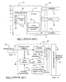
- Fig. 1 is a simplified block diagram showing a memory chip or memory device 12.
- the memory chip 12 may be part of a DIMM (dual in-line memory module) or a PCB (printed circuit board) containing many such memory chips (not shown in Fig. 1 ).
- the memory chip 12 may include a plurality of pins 14 located outside of chip 12 for electrically connecting the chip 12 to other system devices. Some of those pins 14 may constitute memory address pins or address bus 17, data pins or data bus 18, and control pins or control bus 19. It is evident that each of the reference numerals 17-19 designates more than one pin in the corresponding bus. Further, it is understood that the schematic in Fig. 1 is for illustration only. That is, the pin arrangement or configuration in a typical memory chip may not be in the form shown in Fig. 1 .
- a processor or memory controller may communicate with the chip 12 and perform memory read/write operations.
- the processor and the memory chip 12 may communicate using address signals on the address lines or address bus 17, data signals on the data lines or data bus 18, and control signals (e.g., a row address strobe (RAS) signal, a column address strobe (CAS) signal, etc. (not shown)) on the control lines or control bus 19.
- control signals e.g., a row address strobe (RAS) signal, a column address strobe (CAS) signal, etc. (not shown)
- the "width" (i.e., number of pins) of address, data and control buses may differ from one memory configuration to another.
- memory chip 12 of Fig. 1 is simplified to illustrate one embodiment of a memory chip and is not intended to be a detailed illustration of all of the features of a typical memory chip.
- Numerous peripheral devices or circuits may be typically provided along with the memory chip 12 for writing data to and reading data from the memory cells 20. However, these peripheral devices or circuits are not shown in Fig. 1 for the sake of clarity.
- the memory chip 12 may include a plurality of memory cells 20 generally arranged in rows and columns to store data in rows and columns. Each memory cell 20 may store a bit of data.
- a row decode circuit 22 and a column decode circuit 24 may select the rows and columns in the memory cells 20 in response to decoding an address, provided on the address bus 17. Data to/from the memory cells 20 is then transferred over the data bus 18 via sense amplifiers and a data output path (not shown).
- a memory controller (not shown) may provide relevant control signals (not shown) on the control bus 19 to control data communication to and from the memory chip 12 via an I/O (input/output) unit 26.
- the I/O unit 26 may include a number of data output buffers to receive the data bits from the memory cells 20 and provide those data bits or data signals to the corresponding data lines in the data bus 18.
- the I/O unit 26 may further include a clock synchronization unit or delay locked loop (DLL) 28 to synchronize the external system clock (e.g., the clock used by the memory controller (not shown) to clock address, data and control signals between the memory chip 12 and the controller) with the internal clock used by the memory 12 to perform data write/read operations on the memory cells 20.
- DLL delay locked loop
- the memory controller may determine the modes of operation of memory chip 12.
- Some examples of the input signals or control signals (not shown in Fig. 1 ) on the control bus 19 include an External Clock signal, a Chip Select signal, a Row Access Strobe signal, a Column Access Strobe signal, a Write Enable signal, etc.
- the memory chip 12 communicates to other devices connected thereto via the pins 14 on the chip 12. These pins, as mentioned before, may be connected to appropriate address, data and control lines to carry out data transfer (i.e., data transmission and reception) operations.
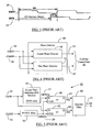
- Fig. 2 depicts a simplified block diagram of the delay-locked loop (DLL) 28 shown in Fig. 1 .
- the DLL 28 receives a reference clock (ClkREF) 30 as an input and generates an output clock or the ClkOut signal 32 at its output.
- a ClkOut signal 32 is, in turn, fed back as a feedback clock (ClkFB) 34 as discussed later.
- ClkFB feedback clock
- the reference clock 30 is interchangeably referred to herein as “ClkREF”, “ClkREF signal”, “Ref clock signal” or “Ref clock”; whereas the feedback clock 34 is interchangeably referred to herein as “ClkFB”, “ClkFB signal”, “FB clock signal” or “FB clock.”
- the reference clock 30 is typically the external system clock serving the microprocessor or a delayed/buffered version of it.
- the system clock 36 is shown buffered through a clock buffer 37.
- the output of the clock buffer 37-i.e., the Ref clock 30-thus is a buffered version of the system clock 36.
- the Ref clock 30 is input into a bank of registers and delay lines 38 as shown in Fig. 2 .
- the registers in the bank 38 control delay lines with phase difference information received from a phase detector 40, as discussed below.
- the bank of registers and delay lines 38 in Fig. 2 is referred to as "the delay line block" hereinbelow.
- the clock output of the delay line block 38-the ClkOut signal 32- is used to provide the internal clock (not shown) used by the SDRAM 12 to perform data read/write operations on memory cells 20 and to transfer the data out of the SDRAM to the data requesting device (e.g., a microprocessor (not shown)).
- the ClkOut 32 is sent to a clock distribution network or clock tree circuit 42 whose output 43 may be coupled to SDRAM clock driver and data output stages (not shown) in the I/O unit 26 to clock the data retrieval and transfer operations.
- the ClkOut signal 32 (and, hence, the FB clock 34) is generated using delay lines in the delay line block 38, which introduces a specific delay into the input Ref clock 30 to obtain the "lock" condition.
- the purpose of the DLL 28 is to align or lock the memory's 12 internal clock (not shown) to the system's external clock (e.g., the system clock 36).
- a phase detector (PD) 40 compares the relative timing of the edges of the system clock 36 and the memory's internal clock (not shown) by comparing the relative timing of their respective representative signals-the Ref clock 30 which relates to the system clock 36, and the FB clock signal 34 which relates to the memory's internal clock-so as to establish the lock condition. As shown in Fig.
- an I/O delay model circuit 44 may be a part of the DLL 28 to function as a buffer or dummy delay circuit for the ClkOut signal 32 before the ClkOut signal 32 is fed into the phase detector 40 as the FB clock 34. It is noted that although the ClkOut signal 32 is shown as an input to the I/O delay model 44, in some practical applications, the ClkOut signal 32 may still be an input to the clock distribution network 42, but another clock signal (not shown) received from the clock distribution network 42 may be fed as an input to the I/O delay model 44 instead of the ClkOut signal 32.
- the output of the I/O model 44 (i.e., the FB clock 34) effectively represents the memory's internal clock, which may be provided through the clock driver and data output stages (not shown) in the I/O unit 26.
- the I/O delay model 44 replicates the intrinsic delay of the clock feedback path, which includes the delay "A" of the system clock input buffer 37 and delay "B" that includes the delay encountered by the ClkOut signal 32 in the output data path (not shown) in the memory 12 prior to the output of the memory's internal clock (not shown).
- the I/O model 44 may be a replica of the system clock receiver circuit (not shown) that includes the external clock buffer 37, and the clock and data output path (not shown) so as to match respective delays imparted by these stages to the system clock 36 and the ClkOut signal 32, thereby making the Ref clock 30 and the FB clock 34 resemble, respectively, the system clock 36 and the internal clock (not shown) of the memory as closely as possible.
- the I/O delay model 44 attempts to maintain the phase relationship between the Ref clock 30 and the FB clock 34 as close as possible to the phase relationship that exists between the system clock 36 and the memory's internal clock (not shown).
- the Ref clock 30 and the FB clock 34 are fed as inputs into the phase detector 40 for phase comparison.
- the SL/SR signal 45 may determine whether the Ref clock 30 should be shifted left (SL) or shifted right (SR) through the appropriate delay units in the delay line block 38 so as to match the phases of the Ref clock 30 and the FB clock 34 to establish the lock condition.
- the SL/SR signal 45 may be supplied to the delay line block 38 via a delay control unit 46, which may control the timing of application of the SL/SR signal 45 by generating a delay adjustment signal 47, which, in effect, serves the same purpose as the SL/SR signal 45 but its application to the delay line block 38 is controlled by the delay control unit 46.
- the delay imparted to the Ref clock 30 by the delay line block 38 operates to adjust the time difference between the output clock (i.e., the FB clock 34) and the input Ref clock 30 until they are aligned.
- the phase detector 40 generates the shift left and shift right signals depending on the detected phase difference or timing difference between the Ref clock 30 and the FB clock 34, as is known in the art.
- Fig. 3 illustrates a timing mismatch between ClkREF 30 and ClkFB 34 operated on by the phase detector 40 in Fig. 2 .
- ClkFB 34 is generated after an intrinsic delay (i.e., the total of delays A and B in Fig. 2 ) of t ID seconds has elapsed since the receipt of the first rising edge of ClkREF 30 by the phase detector 40.
- t D 200ps
- m 10.
- the clock periods of ClkREF 30 and ClkFB 34 remain equal, but there may be a phase difference or timing mismatch ("lag” or “lead") between the two clocks that is detected by the phase detector 40 and adjusted by the delay line block 38 using the SL/SR signal 45 from the phase detector 40.
- lag phase difference or timing mismatch
- Fig. 4 depicts through a block diagram the major circuit elements of the phase detector 40 in Fig. 2 .
- the phase detector 40 may include two phase detection units: a coarse phase detector 50 and a fine phase detector 52.
- the outputs 53-54 of the coarse and fine phase detectors, respectively, are supplied to the delay control unit 46 as respective SL/SR signals.
- the SL/SR signal 45 of Fig. 2 may consist of two separate SL/SR signals, each from one of the corresponding coarse and fine phase detectors 50, 52.
- the coarse phase detector 50 may initially act on ClkREF 30 and ClkFB 34 to instruct the delay line block 38 to provide a coarse delay to ClkREF 30 to establish a coarse phase alignment between ClkREF 30 and ClkFB 34. Thereafter, the fine phase detector 52 may take over and perform "fine tuning" or fine phase alignment of these two clocks to establish a perfect lock condition.
- the delay control unit 46 may ignore any output 54 from the fine phase detector 52 until the output 53 of the coarse phase detector 50 indicates a primary "lock” (albeit, a rudimentary or less than perfect lock) between ClkREF 30 and ClkFB 34. Then the delay control unit 46 receives the output 54 from the fine phase detector 52 to instruct the delay line block 38 to provide a fine delay to ClkREF 30 until a perfect or fine lock between ClkREF 30 and ClkFB 34 is achieved.
- Fig. 5 shows an exemplary block diagram depicting various circuit elements constituting the coarse phase detector 50 depicted in Fig. 4 .
- the coarse phase detector 50 includes a coarse phase detection (PD) window 56 that provides an initial delay of "t PDW " to ClkFB 34 to generate a delayed feedback clock signal (ClkFB2d) 57 at its output.
- the amount of the delay t PDW may be fixed or predetermined.
- Another delay element 58 provides t PDW /2 delay (i.e., half of the delay provided by the coarse PD window 56) to ClkREF 30 to generate a delayed reference clock signal (ClkREFd) 59 at its output.
- the ClkREFd signal 59 clocks the sampler circuits (here, in the form of a set of D flipflops) 60, 62 to sample the feedback clock (ClkFB) 34 and the delayed feedback clock (ClkFB2d) 57 as shown in Fig. 5 .
- the outputs PH1 (64) and PH2 (65) of D flipflops 62 and 60, respectively, represent the value of their respective D inputs (ClkFB 34 or ClkFB2d 57) sampled at the rising edge of ClkREFd 59.
- the values of PH1 and PH2 at any given instant determine the phase of ClkFB 34 with respect to the phase of ClkREF 30 (i.e., whether ClkFB 34 is in phase, 180° out of phase, etc. with respect to ClkREF 30 as discussed below).
- the relation between the phases of PH1 64 and PH2 65 may determine, as discussed in more detail below, whether to shift the reference clock 30 to the left or to the right.
- a majority filter 66 may be provided to receive PH1 (64), PH2 (65), and a counting clock signal (not shown) as inputs, and to responsively generate an appropriate SL/SR signal as the output 53 of the coarse phase detector 50.
- the majority filter 66 may include a binary up/down counter (clocked by a counting clock signal (not shown)), which is incremented or decremented by the values of PH1 and PH2 signals 64-65.
- the counting clock may be the same as the system clock 36 or the reference clock 30.
- a certain number of counting of input clock pulses i.e., clock pulses of the counting clock signal (not shown)
- Such counting may consume time and delay the shifting of the Ref clock 30 and, hence, may delay the establishment of the lock as discussed in detail later hereinbelow.
- Fig. 6 illustrates a phase relationship between the PH1 (64) and PH2 (65) signals generated by the coarse phase detector 50 in Fig. 5 .
- the relationship between the phases of PH1 and PH2 may be used to identify what is the phase of ClkFB 34 with respect to ClkREF 30.
- the term "DP" difference in phase denotes the relative phase of ClkFB 34 with reference to ClkREF 30.
- a shift left (SL) signal may be generated by the coarse phase detector 50 (as illustrated in Fig. 7A ).
- shift right (SR) signal may be generated when appropriate phase relationship between PH1 and PH2 as depicted in Fig. 6 arises.
- the output 53 of the coarse phase detector 50 may indicate a phase equal condition (PHEQ) when a certain phase relationship between PH1 and PH2 exists as shown in Fig. 6 .
- the PHEQ condition may signify that ClkFB 34 is either substantially in phase ( ⁇ 0° phase difference) or substantially 360° out of phase with respect to ClkREF 30.
- Other phase relationships between ClkFB 34 and ClkREF 30 and corresponding function symbols in Fig. 6 are self explanatory and, hence, are not further discussed here.
- Figs. 7A-7C show the timing relationships among various waveforms in the coarse phase detector 50 of Fig. 5 and also shows whether the reference clock should be shifted left or right to establish a lock.
- the coarse phase detector 50 is in the shift left (SL) mode because ClkFB 34 has more than 180° (but less than 360°) phase distortion (180 ⁇ DP ⁇ 360) with respect to ClkREF 30, thereby generating high (or logic "1") values for both PH1 (64) and PH2 (65) signals.
- the DLL 28 increases delay applied to ClkREF 30.
- Fig. 7B shows exemplary signal waveforms for PHEQ mode. As is shown in Fig. 7B (and also in Fig.
- the delay control unit 46 may start receiving output 54 from the fine phase detector 52.
- fine phase detector 52 is active and after several successive PHEQ modes, a stable lock between ClkREF 30 and ClkFB 34 is established.
- Fig. 8 depicts a simplified and exemplary illustration of registers and delay lines in the delay line block 38 and also shows how the reference clock 30 is shifted through the delay lines during initialization of the DLL 28.
- Fig. 8 illustrates sixty-one (61) register-controlled delay lines in the delay line block 38. It is noted that the number of registers and delay lines in Fig. 8 are for illustration only. To make the function of DLL 28 simple, it is assumed that register # 0 (R0) is on or active upon initialization of the DLL 28. This means that the reference clock 30 initially bypasses the delay lines in the block 38. In the example discussed hereinbefore with reference to Fig.
- Fig. 9 illustrates an exemplary set of waveforms for the reference clock 30 and the feedback clock 34 upon initialization of the DLL 28 in Fig. 1 .
- the waveforms in Fig. 9 depict a situation where a forced left shift (ForceSL or Force Shift Left) of the reference clock 30 is performed, even though the DLL 28 may be in the shift right (SR) mode (indicated by the crossed out portion in Fig. 9 ).
- SR shift right
- Such a relatively high value of "m” may extend the time needed to establish a lock, especially when the majority filter 66 is used during DLL initialization as is discussed below with the example in Fig. 10 . It is noted that the ForceSL mode is exited once the PH1 signal goes “high” or assumes a logic "1" value.
- Fig. 10 shows another exemplary set of waveforms for the reference clock 30 and the feedback clock 34 upon initialization of the DLL 28 in Fig. 1 .
- the DLL 28 would be in the shift right (SR) mode upon initialization.
- the DLL 28 would be forced to enter the shift left mode (ForceSL mode) during initialization.
- SR shift right
- ForceSL mode shift left mode
- the "On1x" mode may be enabled during initialization.
- the On1x mode is only enabled during the initialization.
- the DLL 28 enables the shift left (SL) command on every clock cycle (of the reference clock 30), and the majority filter 66 remains disabled during the On1x mode.
- the DLL 28 may not only enter into the ForceSL mode, but may also enter into the On1x mode to perform left shifting on every clock cycle to expedite lock point establishment.
- the On1x mode is typically exited when the DLL 28 enters the PHEQ mode.
- the On1x mode is generally good for slow frequency clocks only (with large t CK ), i.e., the ratio (t CK / t ID ) > 0.5.
- a high frequency reference clock 30 (small t CK ) may cause overshooting between the ClkREF 30 and ClkFB 34 after the On1x mode is exited by the PHEQ signal (which is generated when the DLL 28 enters the PHEQ mode as shown in Fig. 12 ).
- Fig. 11 depicts an exemplary set of waveforms for a high frequency reference clock 30 and the corresponding feedback clock 34 upon initialization of the DLL 28 in Fig. 1 .
- t CK 3ns
- t ID 10ns
- t CK 3ns
- t ID 10ns
- m 10.
- the overshooting results in this case because of small t CK (of ClkREF 30) and long feedback time (t FB ) as discussed with reference to Fig. 12 .
- Fig. 12 shows an exemplary set of waveforms to illustrate the overshooting problem encountered upon the exit of the On1x mode at high clock frequencies. It is noted here that because of a large number of waveforms in Fig. 12 , no reference numerals are provided in Fig. 12 for ease of discussion and illustration. It is seen from Fig. 12 that the DLL 28 enters the ForceSL and On1x modes upon initialization. Thus, the left shifting of ClkREF 30 starts immediately after the first clock cycle of ClkFB 34 is received as indicated by the set of SL clocks at the top in Fig. 12 . The On1x mode shifts ClkREF 30 left on each clock cycle of ClkREf 30 as indicated by the counting of the SL clocks in Fig. 12 .
- phase relation signals PH1 and PH2 are also illustrated in Fig. 12 .
- the PHEQ signal in Fig. 12 is generated when the relation between the PH1 and PH2 signals indicate the PHEQ mode (as illustrated in Fig. 6 ).
- the On1x mode adds four additional left shifts (as shown by clock numbered 11 through 14 in the SL signal in Fig. 12 ) by the time the On1x mode exits by the rising edge of the PHEQ signal. This results in the overshooting illustrated in Fig. 12 , which not only disrupts the phase alignment between ClkREF and ClkFB, but also further slows the lock establishment time by adding extra delays to establish lock.
- the majority filter 66 (which was disabled during the On1x mode) may be needed to establish the lock because ClkREF and ClkFB are still not aligned at the time of On1x mode exit. The use of the majority filter 66 may further add locking delays as discussed hereinbefore with reference to Fig. 10 .
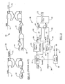
- Figs. 13A and 13B illustrate two exemplary circuits 70, 72, respectively, to generate and terminate ForceSL 74 and On1x 76 signals shown in Fig. 12 .
- the initialization pulse 75 (Init #) is active "low”.
- the Init # signal goes low (preferably in a pulse form) to generate the ForceSL signal 74 (shown in Fig. 12 ) to enter the force shift left mode.
- the On1x signal 76 (shown in Fig. 12 ) is also generated similarly in the circuit 72 of Fig. 13B.
- the ForceSL mode is exited (i.e., the ForceSL signal 74 in Fig. 13B goes low) using the circuit 70 of Fig.
- Fig. 14 depicts a set of waveforms illustrating the wrong ForceSL exit problem due to clock jitter.
- Fig. 12 because of a large number of waveforms in Fig. 14 , no reference numerals are provided in Fig. 14 for ease of discussion and illustration. It was shown and discussed with reference to Figs. 13A-B (and also with reference to Fig. 12 ) that ForceSL mode is exited when PH1 signal goes high. However, at long tCK (slower clock frequencies) and short tID, the clock jitter may cause the ForceSL mode to exit prematurely as shown through the waveforms in Fig. 14 . In the embodiment of Fig. 14 , the On1x mode is also exited together with the ForceSL mode.
- the problem of overshooting in the feedback path may occur, especially at higher frequencies.
- the untimely or wrong ForceSL/On1x exit results in activation of the majority filter 66 (through the Majority Filter Enable signal) to establish the lock.
- the majority filter 66 significantly delays lock establishment, especially during DLL initialization. It is observed here that the wrong ForceSL exit problem may be solved using an appropriate filter, but the On1x overshooting problem may still remain.
- the present disclosure contemplates a method of operating a synchronous circuit.
- the method comprises: applying a reference clock as an input to a delay line as part of the synchronous circuit; generating an output clock at an output of said delay line using the reference clock, generating from said output clock a feedback clock; obtaining from the feedback clock a first delayed feedback clock and a second delayed feedback clock, with the second delayed feedback clock having a fixed amount of delay compared to the first delayed feedback clock; and generating a shift signal to shift the reference clock through the delay line based on a relationship among the phases of the reference clock, the first delayed feedback clock, and the second delayed feedback clock.
- the first delayed feedback clock has a variable amount of delay compared to the feedback clock.
- the present disclosure contemplates a method that comprises: obtaining a reference clock; generating a feedback clock from the reference clock, wherein frequencies of the feedback clock and the reference clock are identical; obtaining a first delayed feedback clock and a second delayed feedback clock from the feedback clock; and shifting the reference clock left or right based on a relationship among the phases of the reference clock, the first delayed feedback clock, and the second delayed feedback clock.
- the present disclosure contemplates a method that comprises: obtaining a reference clock; entering a first shift left mode to shift the reference clock leftward; generating a feedback clock from the reference clock; monitoring a phase relationship between the phases of the reference clock and the feedback clock; and exiting the first shift left mode when the phase relationship indicates that the feedback clock is more than 180° but less than 360° out of phase with the reference clock.
- the present disclosure contemplates a synchronous circuit (e. g., a delay locked loop) constructed to include a coarse phase detector according to the teachings of the present disclosure.
- a synchronous circuit e. g., a delay locked loop
- the present disclosure contemplates a system that comprises a processor, a bus, and a memory device coupled to the processor via the bus and including the synchronous circuit.
- the system and method of the present disclosure generate and terminate clock shift modes during initialization of a synchronous circuit (e.g., a delay-locked loop or DLL).
- a synchronous circuit e.g., a delay-locked loop or DLL.
- the DLL Upon initialization, the DLL is entered into a ForceSL (Force Shift Left) mode and an On1x mode (i.e., left shifting on each clock cycle).
- the feedback clock that tracks the phase of the reference clock (which, in turn, is derived from the system clock) is initially delayed in a coarse phase detector prior to applying it to the coarse phase detection window. Two delayed versions of the feedback clock are sampled by the reference clock to generate a pair of phase information signals, which are then used to establish an advanced phase equal (APHEQ) signal.
- APHEQ advanced phase equal
- the APHEQ signal advances onset of the PHEQ (phase equalization) phase and is used to terminate the ForceSL and On1x modes, thereby preventing wrong ForceSL exit due to clock jitter or feedback path overshooting during On1x exit.
- the avoidance of wrong ForceSL exit and On1x overshooting problems further results in faster DLL locking time.
- Fig. 1 is a simplified block diagram showing a memory chip or memory device
- Fig. 2 depicts a simplified block diagram of the delay-locked loop shown in Fig. 1 ;
- Fig. 3 illustrates a timing mismatch between ClkREF and ClkFB operated on by the phase detector in Fig. 2 ;
- Fig. 4 depicts through a block diagram the major circuit elements of the phase detector in Fig. 2 ;
- Fig. 5 shows an exemplary block diagram depicting various circuit elements constituting the coarse phase detector depicted in Fig. 4 ;
- Fig. 6 illustrates a phase relationship between the PH1 and PH2 signals generated by the coarse phase detector in Fig. 5 ;
- Figs. 7A-7C show the timing relationships among various waveforms in the coarse phase detector of Fig. 5 and also shows whether the reference clock should be shifted left or right to establish a lock;
- Fig. 8 depicts a simplified and exemplary illustration of registers and delay lines in the delay line block and also shows how the reference clock is shifted through the delay lines during initialization of the DLL;
- Fig. 9 illustrates an exemplary set of waveforms for the reference clock and the feedback clock upon initialization of the DLL in Fig. 1 ;
- Fig. 10 shows another exemplary set of waveforms for the reference clock and the feedback clock upon initialization of the DLL in Fig. 1 ;
- Fig. 11 depicts an exemplary set of waveforms for a high frequency reference clock and the corresponding feedback clock upon initialization of the DLL in Fig. 1 ;
- Fig. 12 shows an exemplary set of waveforms to illustrate the overshooting problem encountered upon the exit of the On1x mode at high clock frequencies
- Fig. 13A and 13B illustrate two exemplary circuits to generate and terminate ForceSL and On1x signals, respectively, shown in Fig. 12 ;
- Fig. 14 depicts a set of waveforms illustrating the wrong ForceSL exit problem due to clock jitter
- Fig. 15 shows a coarse phase detector according to one embodiment of the present disclosure
- Fig. 16 illustrates an exemplary circuit layout and corresponding signal waveforms for the controlled delay unit shown in Fig. 15 ;
- Fig. 17 depicts an exemplary set of waveforms illustrating how the overshooting problem illustrated in Fig. 12 is avoided by use of the coarse phase detector of Fig. 15 ;
- Fig. 18 shows an exemplary circuit for the phase control unit of Fig. 15 ;
- Fig. 19 is a block diagram depicting a system in which a coarse phase detector constructed according to the teachings of the present disclosure may be used.
- Fig. 15 shows a coarse phase detector 80 according to one embodiment of the present disclosure.
- the phase detector 80 is similar to the prior art phase detector 50 in Fig. 5 , except for the addition of two circuit elements: a controlled delay unit 82, and a phase control unit 86.
- the presence of units 82 and 86 in the phase detector 80 results in a solution of the problems of wrong ForceSL exit and On1x overshooting discussed before under the "Background" section. It is noted here that the same reference numerals are used to refer to similar circuit elements in Figs. 5 and 15 for the sake of clarity of discussion and ease of comparison between the embodiments in Figs. 5 and 15 .
- a first delay is applied to the feedback clock 34 through the controlled delay unit 82, thereby generating a first delayed feedback clock (FB1) 83.
- the operation of the controlled delay unit 82 is discussed hereinbelow with reference to Fig. 16 .
- the FB1 clock 83 is then applied to the coarse PD window 56 to generate a second delayed feedback clock (FB2) 84.
- the delayed reference clock 59 samples the FB1 clock 83 (through the D flipflop 62) and the FB2 clock 84 (through the D flipflop 60) to generate the PH1 (64) and PH2 (65) signals, respectively, in the manner discussed hereinbefore with reference to Fig. 5 .
- the SL/SR signal output 53 is eventually generated from the PH1 and PH2 signals in the same manner as discussed before with reference to Fig. 5 .
- the phase control unit 86 applies the ForceSL signal 74 to the controlled delay unit 82 to control the application of the delay to ClkFB 34.
- a circuit layout for the phase control unit 86 is provided in Fig. 18 and discussed later hereinbelow. It is noted here, however, that although the same reference numeral "74" is used in Fig. 15 (and, also in Figs. 16 and 18 ) as in Fig. 13A to refer to the ForceSL signal, it is evident that the embodiment in Fig. 13A and that in Figs. 15-18 are different. The use of same reference numerals for identically-named signals is for convenience and ease of discussion only.
- Fig. 16 illustrates an exemplary circuit layout 82 and corresponding signal waveforms for the controlled delay unit 82 shown in Fig. 15 .
- the controlled delay unit 82 applies delay to the ClkFB 34 (thereby generating the first delayed feedback clock 83) based on the signal level of the ForceSL signal 74.
- the controlled delay unit 82 may include a number of delay elements 88 whose output is multiplexed with ClkFB signal 34 using a multiplexer 90 whose output (the FB1 clock 83) is then controlled by the ForceSL signal 74 as shown in Fig. 16 .
- Each delay element 88 provides a unit delay (t D ) to ClkFB 34 as shown.
- Each delay element 88 may consist of a combination of a delay line and a pair of AND gates as shown in Fig. 16 .
- the delay element 88 may be similar to a delay line in the delay line block 38.
- the construction and operation of a unit delay element is well known in the art and, hence, no additional discussion thereof is provided herein. It is noted, however, that the number of delay elements 88 in an implementation of the coarse phase detector 80 may either be fixed (or predetermined) or variable.
- the number of delay elements 88 for a particular coarse phase detector 80 is determined based on the latency of RAS (Row Address Strobe) and CAS (Column Address Strobe) signals from a memory controller (not shown) or on the ratio of the feedback delay (t FB ) to the reference clock cycle (t CK ) (t FB / t CK ).
- RAS Row Address Strobe
- CAS Cold Address Strobe
- Fig. 16 also illustrates the waveforms showing timing relationship between various signals in the controlled delay unit 82.
- the controlled delay unit 82 bypasses the four delay elements 88 once the ForceSL signal 74 goes inactive (or "low”).
- the FB1 clock 83 becomes the same as ClkFB 34 and is no longer a delayed version of ClkFB 34 as can be seen from the waveforms in Fig. 16 . It is noted here that the delay provided by the multiplexer 90 is ignored in depicting the waveforms in Fig. 16 .
- the use of the controlled delay unit 82 to "mirror" the feedback delay (t FB ) by providing that delay to ClkFB 34 through the delay elements 88 in advance of the application of ClkFB 34 to the coarse phase detection window 56 (and also to the sampling circuit 62) results in generation of an Advanced Phase Equal (APHEQ) signal 92 that allows timely termination of the ForceSL and On1x modes without the problems of clock jitter and overshooting as discussed below with reference to Figs. 17 and 18 . That is, the APHEQ signal 92 is generated in advance of or ahead in time of the PHEQ signal 77 shown in Figs. 12-13 to prevent clock overshooting.
- APHEQ Advanced Phase Equal
- Fig. 17 depicts an exemplary set of waveforms illustrating how the overshooting problem illustrated in Fig. 12 is avoided by use of the coarse phase detector 80 of Fig. 15 .
- t FB the feedback delay
- t CK the feedback delay
- the normal termination of On1x mode results in overshooting and it may not be desirable because, at high frequency, such overshooting may result in skipping of several lock points as discussed hereinbefore with reference to Fig. 12 .
- t ID t ID
- t D t D , etc.
- the values of various timing parameters are also the same in Figs. 12 and 17 .
- Fig. 17 it is seen from Fig. 17 that the problem of overshooting has been eliminated. That is, no feedback path overshooting occurs in Fig. 17 even after the On1x mode is disabled.
- the generation of FB1 and FB2 clocks in the embodiment of Fig. 15 allows the coarse PD window 56 to "see" the phase information between ClkREF 30 and ClkFB 34 not delayed by t FB (as was the case in the embodiment of Fig. 12 ), but advanced by t FB (by use of the controlled delay unit 82 in Fig. 15 ).
- FIG. 15 results in generation of the APHEQ phase in advance of the generation of the "regular" PHEQ phase as shown in Fig. 17 .
- the On1x mode and the ForceSL mode are exited by APHEQ signal 92 ( Fig. 18 ), which is generated during the SL mode, i.e., when the phase difference between ClkFB 34 and ClkREF 30 is more than 180° but less than 360° as shown in Fig. 6 .
- the coarse phase detector 80 of Fig. 15 generates a "dip" in the waveform of PH2 (as shown in Fig.
- the waveforms shown therein are exemplary in nature.
- the values of PH1 and PH2 signals shown in Fig. 17 may differ from one reference clock 30 to another, and may not even be identical from one set of DLL initialization waveforms to another because slightly different timing relationships may be present between FB1 (83), FB2 (84) and ClkREFd (59) clocks upon each DLL initialization.
- generation of APHEQ phase (and, hence, termination of ForceSL and On1x modes) relies on specific values of both PH1 and PH2 signals and, hence, the timing of generation of APHEQ phase may be affected by PH1 and PH2 signals only.
- both PH1 and PH2 signals are used to terminate the ForceSL mode (via activation of the APHEQ phase), instead of just the PH1 signal terminating the ForceSL mode as in the embodiment of Fig. 12 .
- the On1x mode and the ForceSL mode in Fig. 17 are terminated as soon as the first occurrence of the specific set of values for PH1 and PH2 (resulting in generation of the APHEQ phase), i.e., the value of PH1 is "high” or logic "1” and the value of PH2 is "low” or logic "0".
- the same set of values for PH1 and PH2 results in the later generation of the PHEQ phase, the termination of the On1x mode and the ForceSL mode in the embodiment of Fig. 17 is not made dependent on this later generated PHEQ phase (which was the case in the embodiment of Fig. 12 ).
- the On1x mode may be deactivated after ForceSL mode as discussed before (e.g., upon onset of the PHEQ phase succeeding the APHEQ phase shown in Fig. 17 ).
- the coarse phase detector 80 of Fig. 15 would prevent wrong ForceSL exit due to clock jitter or feedback clock overshooting upon On1x mode exit.
- the problem of wrong ForceSL exit due to clock jitter is avoided because ForceSL mode is exited by APHEQ phase (or the APHEQ signal 92 in Fig. 18 ), which may occur far from the P180 boundary ( Fig.
- the wrong ForceSL exit occurs at the P180 boundary (denoted in the waveform for the PH2 signal in Fig. 14 ), whereas, in Fig. 17 , the ForceSL mode is exited during the SL mode (because the APHEQ signal terminating the ForceSL mode is generated during the SL mode) and far from the P 180 boundary. Further, in the prior art, the ForceSL mode was terminated using the value of the PH1 signal only as discussed hereinbefore with reference to, for example, Fig. 12 and also shown in Fig. 14 . On the other hand, in the embodiment of Fig. 17 , the ForceSL mode is disabled using the values of PH1 and PH2 signals both, which further avoids wrong ForceSL exit due to clock jitter.
- the phases of ClkREF 30 and ClkFB 34 may not be aligned at the time of onset of the APHEQ phase as shown, for example, in Fig. 17 .
- the generation of the APHEQ signal 92 ( Fig. 18 ) may not mean that ClkREF 30 and ClkFB 34 are in fact aligned.
- the occurrence of the APHEQ phase signals the termination of the ForceSL mode (and also the On1x mode in Fig. 17 ) so as to allow proper time delay to achieve coarse locking of ClkREF and ClkFB without being affected by the problems of clock jitter or overshooting.
- the On1x mode may be exited not by the onset of the APHEQ phase, but by the succeeding PHEQ phase in the manner discussed hereinbefore with reference to Fig. 12 .
- the problem of feedback clock overshooting may not happen because of the manner in which the PH1 and PH2 signals are generated by the coarse phase detector 80 using the phase relationship among two delayed versions of the feedback clock 34 as discussed before.
- Fig. 18 shows an exemplary circuit for the phase control unit 86 of Fig. 15 .
- the circuit in Fig. 18 is substantially similar to that in Fig. 13B and, hence, no detailed explanation is provided for Fig. 18 . It is observed from a comparison of Figs. 13B and 18 that the APHEQ signal 92 in Fig. 18 is used in place of the PHEQ signal 77 in Fig. 13B to terminate both the ForceSL and On1x modes.
- the ForceSL signal 74 and the On1x signal 76 are generated together using the Init# signal in the same manner as discussed before with reference to Figs. 13A-B.
- the APHEQ signal 92 (which is generated in advance of the "regular" PHEQ signal 77) is used in Fig. 18 to terminate both the ForceSL and the On1x modes.
- the APHEQ signal 92 is used in the same manner as the PHEQ signal 77 in Fig. 13B to achieve the desired terminations.
- the term "APHEQ" is used to distinguish the phase equal signal PHEQ 77 from the APHEQ signal 92, in practice, both of these signals are part of the same PHEQ phase shown in Fig. 6 and as indicated by the PHEQ waveform in Fig. 17 .
- the APHEQ phase is nothing but the first occurrence of the PHEQ phase during DLL initialization.
- the PHEQ phase may occur (as indicated by the PHEQ signal in Fig. 17 going "high” (or logic "1 ”) again after APHEQ phase is over as shown in Fig. 17 .
- the coarse phase detector 80 may be part of a DLL (e.g., the DLL 28 suitably modified to include the detector 80), which, as discussed before, is one type of synchronous circuit that can be internal to any integrated circuit including, for example, an SDRAM memory unit.
- a DLL e.g., the DLL 28 suitably modified to include the detector 80
- the coarse phase detector 80 of the present disclosure may be used with any other synchronous circuit including, for example, a synchronous mirror delay circuit (SMD) that may also be used for clock synchronization in various electronic integrated circuits including, for example, SDRAMs.
- SMD synchronous mirror delay circuit
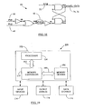
- Fig. 19 is a block diagram depicting a system 100 in which a coarse phase detector (e.g., the detector 80 in Fig. 15 ) constructed according to the teachings of the present disclosure may be used.
- the system 100 may include a data processing unit or computing unit 102 that includes a processor 104 for performing various computing functions, such as executing specific software to perform specific calculations or data processing tasks.
- the computing unit 102 may also include memory devices 106 that are in communication with the processor 104 through a bus 108.
- the bus 108 may include an address bus (not shown), a data bus (not shown), and a control bus (not shown).
- Each of the memory device 106 can be a dynamic random access memory (DRAM) chip or another type of memory circuits such as SRAM (Static Random Access Memory) chip or Flash memory.
- the DRAM could be a synchronous DRAM commonly referred to as SGRAM (Synchronous Graphics Random Access Memory), SDRAM (Synchronous Dynamic Random Access Memory), SDRAM II, or DDR SDRAM (Double Data Rate SDRAM), as well as Synchlink or Rambus DRAMs.
- SGRAM Synchronous Graphics Random Access Memory
- SDRAM Synchronous Dynamic Random Access Memory
- SDRAM II Secure Data Rate SDRAM
- DDR SDRAM Double Data Rate SDRAM
- Synchlink or Rambus DRAMs Synchlink or Rambus DRAMs.
- the processor 104 can perform a plurality of functions based on information and data stored in the memory devices 106.
- the processor 104 can be a microprocessor, digital signal processor, embedded processor, micro-controller, dedicated memory test chip, or the like
- Each of the memory devices 106 may have construction similar to that shown in Fig. 1 , with the exception that the DLL unit 28 may include the coarse phase detector 80 of Fig. 15 instead of the prior art coarse phase detector 50 shown in Fig. 5 .
- a memory controller 110 controls data communication to and from the memory devices 106 in response to control signals (not shown) received from the processor 104 over the bus 112.
- the memory controller 110 may include a command decode circuit (not shown).
- the command decode circuit may receive the input control signals (on the bus 112) (not shown) to determine the modes of operation of one or more of the memory devices 106.
- Some examples of the input signals or control signals (not shown in Fig. 19 ) on the bus 112 (and also on the bus 108) include an External Clock signal, a Chip Select signal, a Row Access Strobe signal, a Column Access Strobe signal, a Write Enable signal, etc.
- the system 100 may include one or more input devices 114 (e.g., a keyboard, a mouse, etc.) connected to the computing unit 102 to allow a user to manually input data, instructions, etc., to operate the computing unit 102.
- One or more output devices 116 connected to the computing unit 102 may also be provided as part of the system 100 to display or otherwise output data generated by the processor 104. Examples of output devices 116 include printers, video terminals or video display units (VDUs).
- the system 100 also includes one or more data storage devices 118 connected to the data processing unit 102 to allow the processor 104 to store data in or retrieve data from internal or external storage media (not shown). Examples of typical data storage devices 118 include drives that accept hard and floppy disks, CD-ROMs (compact disk read-only memories), and tape cassettes.
- the foregoing describes a system and method to generate and terminate clock shift modes during initialization of a synchronous circuit (e.g., a delay-locked loop or DLL).
- a synchronous circuit e.g., a delay-locked loop or DLL.
- the DLL Upon initialization, the DLL is entered into a ForceSL (Force Shift Left) mode and an On1x mode (i.e., left shifting on each clock cycle).
- the feedback clock that tracks the phase of the reference clock (which, in turn, is derived from the system clock) is initially delayed in a coarse phase detector prior to applying it to the coarse phase detection window. Two delayed versions of the feedback clock are sampled by the reference clock to generate a pair of phase information signals, which are then used to establish an advanced phase equal (APHEQ) signal.
- APHEQ advanced phase equal
- the APHEQ signal advances onset of the PHEQ (phase equalization) phase and is used to terminate the ForceSL and On1x modes, thereby preventing wrong ForceSL exit due to clock jitter or feedback path overshooting during On1x exit.
- the avoidance of wrong ForceSL exit and On1x overshooting problems further results in faster DLL locking time.
Description
- The present disclosure generally relates to synchronous circuits and, more particularly, to a system and method to generate and terminate clock shift modes during initialization of a synchronous circuit.
- Most digital logic implemented on integrated circuits is clocked synchronous sequential logic. In electronic devices such as synchronous dynamic random access memory circuits (SDRAM), microprocessors, digital signal processors, etc., the processing storage, and retrieval of information is coordinated or synchronized with a clock signal. The speed and stability of the clock signal determines to a large extent the data rate at which a circuit can function. Many high speed integrated circuit devices, such as SDRAMs, microprocessors, etc., rely upon clock signals to control the flow of commands, data, addresses, etc., into, through and out of the devices.
- In SDRAMs or other semiconductor memory devices, it is desirable to have the data output from the memory synchronized with the system clock that also serves the microprocessor. Delay-locked loops (DLLs) are synchronous circuits used in SDRAMs to synchronize an external clock (e.g., the system clock serving a microprocessor) and an interval clock (e.g., the clock used internally within the SDRAM to perform data read/write operations on various memory cells) with each other. Typically, a DLL is a feedback circuit that operates to feed back a phase difference-related signal to control a delay line, until the timing of one clock signal (e.g., the system clock) is advanced or delayed until its rising edge is coincident (or "locked") with the rising edge of a second clock signal (e.g., the memory internal clock).
-
U.S. Published Application No. 2002/0036527 discloses a DLL circuit having edge detecting/phase comparing portion 2 that generates an original comparison signal that is set to logic "1" when the rise-up of feedback clock FBCLK is prior to the rise-up of reference clock RCLK, and also set to logic "0" when the rise-up of the feedback clock FBCLK is subsequent to the rise-up of the reference clock RCLK, outputs the original comparison signal as subsequent phase comparison result CMPR when it is detected that the level of the reference clock RCLK and the level of the feedback clock FBCLK are varied in same directions within time T0, and keeps the output logical level of the phase comparison result CMPR and outputs it as subsequent phase comparison result CMPR when it is detected that the level of the reference clock RCLK and the feedback clock FBCLK are varied in opposite directions within the time T0.
U.S. Published Application No. 2002/0043996 discloses a DLL circuit that includes a delay line having a configuration with delay stages receiving alternate complementary clock signals ECK and /ECK having an adjusted phase difference therebetween. A capacitor can be used to adjust the phase difference between signals ECK and /ECK to allow the delay line to provide an amount of delay-varying minutely. Preferably, for a fast clock, delay adjustment starts with a shift register having an initial value providing an intermediate amount of delay, and for a slow clock, delay adjustment starts with the shift register having an initial value providing a minimal amount of delay. There can be provided a semiconductor device provided with a DLL circuit accommodating a fast clock with reduced jitter.
U.S. Patent No. 6,807,868 discloses an improved edge-triggered fully digital delay locked loop (DLL), which maintains reliable synchronization from startup and in spite of system clock jitter. An internal clock signal is synchronized with a reference clock signal by propagating the reference clock signal through a variable digital delay path. A wide phase detection region surrounds a selected rising edge of the internal clock signal. The DLL loop is open as long as the internal clock signal and a target edge of the reference clock signal are not simultaneously within the phase detection region. To achieve a DLL locked condition, the variable delay is increased from a minimum setting until the edge of the phase detection region is shifted in time just past the target edge of the reference clock. Once the DLL loop has been closed, a clock jitter filter is enabled to reject reference clock jitter effects on the DLL locked condition. A digital phase detector controls the delay line propagation delay to establish synchronization between the internal clock and the reference clock. Unused delay elements within the variable delay path are deactivated to save power.
European Patent Application No.EP1 276 240 discloses a method and apparatus to ensure DLL locking at a minimum delay. In one embodiment, a DLL circuit includes a phase detector, a counter, a programmable delay line, and a counter control circuit. Upon initialization of the DLL circuit, the counter control circuit is configured to cause the counter to count increment, regardless of the phase relationship between a reference clock signal and the output clock signal. The counter continues incrementing, thereby changing the phase relationship between the reference clock signal and the output clock signal by adjusting the delay of the programmable delay line. This eventually results in a phase lock between the reference clock signal and the output clock signal at a minimum delay. Once the DLL achieves a phase lock between the reference clock signal and the output clock signal, the counter increments or decrements its count to maintain or re-acquire a lock. -
Fig. 1 is a simplified block diagram showing a memory chip ormemory device 12. Thememory chip 12 may be part of a DIMM (dual in-line memory module) or a PCB (printed circuit board) containing many such memory chips (not shown inFig. 1 ). Thememory chip 12 may include a plurality ofpins 14 located outside ofchip 12 for electrically connecting thechip 12 to other system devices. Some of thosepins 14 may constitute memory address pins oraddress bus 17, data pins ordata bus 18, and control pins orcontrol bus 19. It is evident that each of the reference numerals 17-19 designates more than one pin in the corresponding bus. Further, it is understood that the schematic inFig. 1 is for illustration only. That is, the pin arrangement or configuration in a typical memory chip may not be in the form shown inFig. 1 . - A processor or memory controller (not shown) may communicate with the
chip 12 and perform memory read/write operations. The processor and thememory chip 12 may communicate using address signals on the address lines oraddress bus 17, data signals on the data lines ordata bus 18, and control signals (e.g., a row address strobe (RAS) signal, a column address strobe (CAS) signal, etc. (not shown)) on the control lines orcontrol bus 19. The "width" (i.e., number of pins) of address, data and control buses may differ from one memory configuration to another. - Those of ordinary skill in the art will readily recognize that
memory chip 12 ofFig. 1 is simplified to illustrate one embodiment of a memory chip and is not intended to be a detailed illustration of all of the features of a typical memory chip. Numerous peripheral devices or circuits may be typically provided along with thememory chip 12 for writing data to and reading data from thememory cells 20. However, these peripheral devices or circuits are not shown inFig. 1 for the sake of clarity. - The
memory chip 12 may include a plurality ofmemory cells 20 generally arranged in rows and columns to store data in rows and columns. Eachmemory cell 20 may store a bit of data. Arow decode circuit 22 and acolumn decode circuit 24 may select the rows and columns in thememory cells 20 in response to decoding an address, provided on theaddress bus 17. Data to/from thememory cells 20 is then transferred over thedata bus 18 via sense amplifiers and a data output path (not shown). A memory controller (not shown) may provide relevant control signals (not shown) on thecontrol bus 19 to control data communication to and from thememory chip 12 via an I/O (input/output)unit 26. The I/O unit 26 may include a number of data output buffers to receive the data bits from thememory cells 20 and provide those data bits or data signals to the corresponding data lines in thedata bus 18. The I/O unit 26 may further include a clock synchronization unit or delay locked loop (DLL) 28 to synchronize the external system clock (e.g., the clock used by the memory controller (not shown) to clock address, data and control signals between thememory chip 12 and the controller) with the internal clock used by thememory 12 to perform data write/read operations on thememory cells 20. - The memory controller (not shown) may determine the modes of operation of
memory chip 12. Some examples of the input signals or control signals (not shown inFig. 1 ) on thecontrol bus 19 include an External Clock signal, a Chip Select signal, a Row Access Strobe signal, a Column Access Strobe signal, a Write Enable signal, etc. Thememory chip 12 communicates to other devices connected thereto via thepins 14 on thechip 12. These pins, as mentioned before, may be connected to appropriate address, data and control lines to carry out data transfer (i.e., data transmission and reception) operations. -
Fig. 2 depicts a simplified block diagram of the delay-locked loop (DLL) 28 shown inFig. 1 . TheDLL 28 receives a reference clock (ClkREF) 30 as an input and generates an output clock or theClkOut signal 32 at its output. AClkOut signal 32 is, in turn, fed back as a feedback clock (ClkFB) 34 as discussed later. Thereference clock 30 is interchangeably referred to herein as "ClkREF", "ClkREF signal", "Ref clock signal" or "Ref clock"; whereas thefeedback clock 34 is interchangeably referred to herein as "ClkFB", "ClkFB signal", "FB clock signal" or "FB clock." Thereference clock 30 is typically the external system clock serving the microprocessor or a delayed/buffered version of it. In the embodiment ofFig. 2 , thesystem clock 36 is shown buffered through aclock buffer 37. The output of the clock buffer 37-i.e., the Ref clock 30-thus is a buffered version of thesystem clock 36. In a register controlled DLL, theRef clock 30 is input into a bank of registers anddelay lines 38 as shown inFig. 2 . The registers in thebank 38 control delay lines with phase difference information received from aphase detector 40, as discussed below. For the ease of discussion, the bank of registers anddelay lines 38 inFig. 2 is referred to as "the delay line block" hereinbelow. - The clock output of the delay line block 38-the ClkOut signal 32-is used to provide the internal clock (not shown) used by the
SDRAM 12 to perform data read/write operations onmemory cells 20 and to transfer the data out of the SDRAM to the data requesting device (e.g., a microprocessor (not shown)). Thus, as shown inFig. 2 , theClkOut 32 is sent to a clock distribution network orclock tree circuit 42 whoseoutput 43 may be coupled to SDRAM clock driver and data output stages (not shown) in the I/O unit 26 to clock the data retrieval and transfer operations. As can be seen fromFig. 2 , the ClkOut signal 32 (and, hence, the FB clock 34) is generated using delay lines in thedelay line block 38, which introduces a specific delay into theinput Ref clock 30 to obtain the "lock" condition. - As noted before, the purpose of the
DLL 28 is to align or lock the memory's 12 internal clock (not shown) to the system's external clock (e.g., the system clock 36). A phase detector (PD) 40 compares the relative timing of the edges of thesystem clock 36 and the memory's internal clock (not shown) by comparing the relative timing of their respective representative signals-theRef clock 30 which relates to thesystem clock 36, and theFB clock signal 34 which relates to the memory's internal clock-so as to establish the lock condition. As shown inFig. 2 , an I/Odelay model circuit 44 may be a part of theDLL 28 to function as a buffer or dummy delay circuit for theClkOut signal 32 before theClkOut signal 32 is fed into thephase detector 40 as theFB clock 34. It is noted that although theClkOut signal 32 is shown as an input to the I/O delay model 44, in some practical applications, theClkOut signal 32 may still be an input to theclock distribution network 42, but another clock signal (not shown) received from theclock distribution network 42 may be fed as an input to the I/O delay model 44 instead of theClkOut signal 32. In any event, the output of the I/O model 44 (i.e., the FB clock 34) effectively represents the memory's internal clock, which may be provided through the clock driver and data output stages (not shown) in the I/O unit 26. The I/O delay model 44 replicates the intrinsic delay of the clock feedback path, which includes the delay "A" of the systemclock input buffer 37 and delay "B" that includes the delay encountered by theClkOut signal 32 in the output data path (not shown) in thememory 12 prior to the output of the memory's internal clock (not shown). Thus, the I/O model 44 may be a replica of the system clock receiver circuit (not shown) that includes theexternal clock buffer 37, and the clock and data output path (not shown) so as to match respective delays imparted by these stages to thesystem clock 36 and theClkOut signal 32, thereby making theRef clock 30 and theFB clock 34 resemble, respectively, thesystem clock 36 and the internal clock (not shown) of the memory as closely as possible. Thus, the I/O delay model 44 attempts to maintain the phase relationship between theRef clock 30 and theFB clock 34 as close as possible to the phase relationship that exists between thesystem clock 36 and the memory's internal clock (not shown). - The
Ref clock 30 and theFB clock 34 are fed as inputs into thephase detector 40 for phase comparison. The output of the PD 40-a shift left (SL)/shift right (SR) signal 45-controls the amount of delay imparted to theClkREF 30 by thedelay line block 38. The SL/SR signal 45 may determine whether theRef clock 30 should be shifted left (SL) or shifted right (SR) through the appropriate delay units in thedelay line block 38 so as to match the phases of theRef clock 30 and theFB clock 34 to establish the lock condition. The SL/SR signal 45 may be supplied to thedelay line block 38 via adelay control unit 46, which may control the timing of application of the SL/SR signal 45 by generating a delay adjustment signal 47, which, in effect, serves the same purpose as the SL/SR signal 45 but its application to thedelay line block 38 is controlled by thedelay control unit 46. The delay imparted to theRef clock 30 by thedelay line block 38 operates to adjust the time difference between the output clock (i.e., the FB clock 34) and theinput Ref clock 30 until they are aligned. Thephase detector 40 generates the shift left and shift right signals depending on the detected phase difference or timing difference between theRef clock 30 and theFB clock 34, as is known in the art. -
Fig. 3 illustrates a timing mismatch betweenClkREF 30 andClkFB 34 operated on by thephase detector 40 inFig. 2 . As is seen fromFig. 3 ,ClkFB 34 is generated after an intrinsic delay (i.e., the total of delays A and B inFig. 2 ) of tID seconds has elapsed since the receipt of the first rising edge ofClkREF 30 by thephase detector 40. The mismatch between the timing ofClkREF 30 andClkFB 34 is corrected by thephase detector 40 by instructing thedelay line block 38 with appropriate shift left (SL) or shift right (SR)indication 45 to provide a delay equal to m*tD, where "m" is the number of delay elements or delay lines in the delay line block 38 (m = 0,1,2,3,...) and "tD" is the delay provided by a single delay element or delay line. For example, if the clock period (tCK) of theRef clock 30 is 12ns and tID = 10ns, then theDLL 28 has to push out the rising edge ofClkFB 34 orleft shift ClkREF 30 by 2ns (tCK-tID = 2ns) to establish a "lock" (i.e., the rising edges of theRef clock 30 and theFB clock 34 are substantially "aligned" or "synchronized" or almost "in phase"). In this example, if tD = 200ps, then m =10. As is known in the art, the clock periods ofClkREF 30 andClkFB 34 remain equal, but there may be a phase difference or timing mismatch ("lag" or "lead") between the two clocks that is detected by thephase detector 40 and adjusted by thedelay line block 38 using the SL/SR signal 45 from thephase detector 40. -
Fig. 4 depicts through a block diagram the major circuit elements of thephase detector 40 inFig. 2 . Thephase detector 40 may include two phase detection units: acoarse phase detector 50 and afine phase detector 52. The outputs 53-54 of the coarse and fine phase detectors, respectively, are supplied to thedelay control unit 46 as respective SL/SR signals. Thus, in the embodiment ofFig. 4 , the SL/SR signal 45 ofFig. 2 may consist of two separate SL/SR signals, each from one of the corresponding coarse andfine phase detectors coarse phase detector 50 may initially act onClkREF 30 andClkFB 34 to instruct thedelay line block 38 to provide a coarse delay toClkREF 30 to establish a coarse phase alignment betweenClkREF 30 andClkFB 34. Thereafter, thefine phase detector 52 may take over and perform "fine tuning" or fine phase alignment of these two clocks to establish a perfect lock condition. During operation of thecoarse phase detector 50, thedelay control unit 46 may ignore anyoutput 54 from thefine phase detector 52 until theoutput 53 of thecoarse phase detector 50 indicates a primary "lock" (albeit, a rudimentary or less than perfect lock) betweenClkREF 30 andClkFB 34. Then thedelay control unit 46 receives theoutput 54 from thefine phase detector 52 to instruct thedelay line block 38 to provide a fine delay toClkREF 30 until a perfect or fine lock betweenClkREF 30 andClkFB 34 is achieved. -
Fig. 5 shows an exemplary block diagram depicting various circuit elements constituting thecoarse phase detector 50 depicted inFig. 4 . Thecoarse phase detector 50 includes a coarse phase detection (PD)window 56 that provides an initial delay of "tPDW" toClkFB 34 to generate a delayed feedback clock signal (ClkFB2d) 57 at its output. The amount of the delay tPDW may be fixed or predetermined. Anotherdelay element 58 provides tPDW/2 delay (i.e., half of the delay provided by the coarse PD window 56) toClkREF 30 to generate a delayed reference clock signal (ClkREFd) 59 at its output. TheClkREFd signal 59 clocks the sampler circuits (here, in the form of a set of D flipflops) 60, 62 to sample the feedback clock (ClkFB) 34 and the delayed feedback clock (ClkFB2d) 57 as shown inFig. 5 . The outputs PH1 (64) and PH2 (65) ofD flipflops ClkFB 34 or ClkFB2d 57) sampled at the rising edge ofClkREFd 59. The values of PH1 and PH2 at any given instant determine the phase ofClkFB 34 with respect to the phase of ClkREF 30 (i.e., whetherClkFB 34 is in phase, 180° out of phase, etc. with respect toClkREF 30 as discussed below). The relation between the phases ofPH1 64 andPH2 65 may determine, as discussed in more detail below, whether to shift thereference clock 30 to the left or to the right. Amajority filter 66 may be provided to receive PH1 (64), PH2 (65), and a counting clock signal (not shown) as inputs, and to responsively generate an appropriate SL/SR signal as theoutput 53 of thecoarse phase detector 50. Although the construction of themajority filter 66 is not shown here, it is known in the art that themajority filter 66 may include a binary up/down counter (clocked by a counting clock signal (not shown)), which is incremented or decremented by the values of PH1 and PH2 signals 64-65. The counting clock may be the same as thesystem clock 36 or thereference clock 30. However, it is noted that a certain number of counting of input clock pulses (i.e., clock pulses of the counting clock signal (not shown)) may be required by the counter in themajority filter 66 before an SL or SR signal can be output. For example, themajority filter 66 may always count up to four input clock cycles (c = 4) before generating an SL or SR indication. Such counting may consume time and delay the shifting of theRef clock 30 and, hence, may delay the establishment of the lock as discussed in detail later hereinbelow. -
Fig. 6 illustrates a phase relationship between the PH1 (64) and PH2 (65) signals generated by thecoarse phase detector 50 inFig. 5 . As is shown inFig. 6 , the relationship between the phases of PH1 and PH2 may be used to identify what is the phase ofClkFB 34 with respect toClkREF 30. InFig. 6 , the term "DP" (difference in phase) denotes the relative phase ofClkFB 34 with reference toClkREF 30. Thus, for example, when both PH1 and PH2 achieve "high" or logic "1" values after their respective rising edges, that may indicate thatClkFB 34 is more than 180° but less than 360° out of phase with respect toClkREF 30 as shown inFig. 6 . When this phase relationship betweenClkFB 34 andClkREF 30 is in effect, a shift left (SL) signal may be generated by the coarse phase detector 50 (as illustrated inFig. 7A ). Similarly, shift right (SR) signal may be generated when appropriate phase relationship between PH1 and PH2 as depicted inFig. 6 arises. Theoutput 53 of thecoarse phase detector 50 may indicate a phase equal condition (PHEQ) when a certain phase relationship between PH1 and PH2 exists as shown inFig. 6 . The PHEQ condition may signify thatClkFB 34 is either substantially in phase (~0° phase difference) or substantially 360° out of phase with respect toClkREF 30. Other phase relationships betweenClkFB 34 and ClkREF 30 and corresponding function symbols inFig. 6 are self explanatory and, hence, are not further discussed here. -
Figs. 7A-7C show the timing relationships among various waveforms in thecoarse phase detector 50 ofFig. 5 and also shows whether the reference clock should be shifted left or right to establish a lock. InFig. 7A , thecoarse phase detector 50 is in the shift left (SL) mode becauseClkFB 34 has more than 180° (but less than 360°) phase distortion (180<DP<360) with respect toClkREF 30, thereby generating high (or logic "1") values for both PH1 (64) and PH2 (65) signals. During the SL mode, theDLL 28 increases delay applied toClkREF 30.Fig. 7B shows exemplary signal waveforms for PHEQ mode. As is shown inFig. 7B (and also inFig. 6 ), in the PHEQ mode, the value of PH1 is "high" or logic "1" whereas the value of PH2 is "low" or logic "0." These values are generated when the phase ofClkFB 34 is similar (~0° or ~360° phase difference) to the phase ofClkREF 30. When thecoarse phase detector 50 enters the PHEQ mode, thedelay control unit 46 may start receivingoutput 54 from thefine phase detector 52. Thus, during PHEQ mode,fine phase detector 52 is active and after several successive PHEQ modes, a stable lock betweenClkREF 30 andClkFB 34 is established.Fig. 7C , on the other hand, shows the shift right (SR) mode of thecoarse phase detector 50 because the phase distortion betweenClkFB 34 andClkREF 30 is more than 0° but less than 180° (0<DP<180), thereby generating a "low" or logic "0" value for both PH1 and PH2 signals as shown. During the SR mode, theDLL 28 decreases delay applied toClkREF 30. Although the waveforms for the 180° phase distortion case (represented by the function symbol "P180" inFig. 6 ) are not shown inFigs. 7A-7C , it is noted here that when the phase ofClkFB 34 is around 180° out of phase withClkREF 30, thecoarse phase detector 50 enters the SL mode as depicted inFig. 6 . -
Fig. 8 depicts a simplified and exemplary illustration of registers and delay lines in thedelay line block 38 and also shows how thereference clock 30 is shifted through the delay lines during initialization of theDLL 28.Fig. 8 illustrates sixty-one (61) register-controlled delay lines in thedelay line block 38. It is noted that the number of registers and delay lines inFig. 8 are for illustration only. To make the function ofDLL 28 simple, it is assumed that register # 0 (R0) is on or active upon initialization of theDLL 28. This means that thereference clock 30 initially bypasses the delay lines in theblock 38. In the example discussed hereinbefore with reference toFig. 3 , it was noted that if tCK = 12ns, tID = 10ns, and tD = 200ps, then theDLL 28 would need m =10, i.e.,DLL 28 would add delays through ten delay lines. Thus, in this example, ten left shifts (SLs) would be applied toClkREF 30 from the initial entry point (R0) and register # 10 (R10) will represent the lock point. It was noted before that a left shift adds a delay whereas a right shift reduces a delay. - It is observed that during initialization of
DLL 28, the SR (shift right) mode is not allowed, even though theDLL 28 could be in the SR region (e.g., the timing relationship between various clock waveforms may be similar to that inFig. 7C ) because there is no register on the right side of register # 0 (R0) inFig. 8 . -
Fig. 9 illustrates an exemplary set of waveforms for thereference clock 30 and thefeedback clock 34 upon initialization of theDLL 28 inFig. 1 . The waveforms inFig. 9 depict a situation where a forced left shift (ForceSL or Force Shift Left) of thereference clock 30 is performed, even though theDLL 28 may be in the shift right (SR) mode (indicated by the crossed out portion inFig. 9 ). For example, for the waveforms inFig. 9 , if tCK = 8ns, tID = 10ns and tD =200ps, then DLL 28 would need 6ns of additional (forced left shift) delays to establish a lock upon initialization of theDLL 28 because, inFig. 9 , 6ns = 2tCK-tID = m * tD. With the foregoing values, the value of "m" (i.e., the number of delay lines or delay elements) needed to establish a lock is m = 30. Such a relatively high value of "m" may extend the time needed to establish a lock, especially when themajority filter 66 is used during DLL initialization as is discussed below with the example inFig. 10 . It is noted that the ForceSL mode is exited once the PH1 signal goes "high" or assumes a logic "1" value. -
Fig. 10 shows another exemplary set of waveforms for thereference clock 30 and thefeedback clock 34 upon initialization of theDLL 28 inFig. 1 . For the timing relationship illustrated inFig. 10 , theDLL 28 would be in the shift right (SR) mode upon initialization. However, as discussed with reference toFig. 9 , theDLL 28 would be forced to enter the shift left mode (ForceSL mode) during initialization. For the waveforms inFig. 10 , if tCK = 9.8ns, tID = 10ns, and tD = 200ps, then theDLL 28 has to shift left by 9.6ns (m*tD) using the ForceSL mode because 9.6ns = 2*tCK-tID= m*tD. With the foregoing values, the value of "m" (i.e., the number of delay lines or delay elements) needed to establish a lock is m = 48. Therefore, ifDLL 28 uses the majority filter 66 (with counting interval c = 4, as mentioned before by way of an example with reference toFig. 5 ) to establish lock during initialization, then 192 clock cycles may be needed to establish the lock point because c * m = 4 * 48 =192 tCK. Hence, the use ofmajority filter 66 during initialization may significantly slow down the lock point establishment. This example illustrates the need to reduce the time needed to establish a lock. - To reduce the lock time upon initialization of the
DLL 28, the "On1x" mode may be enabled during initialization. Typically, the On1x mode is only enabled during the initialization. Further, during the On1x mode, theDLL 28 enables the shift left (SL) command on every clock cycle (of the reference clock 30), and themajority filter 66 remains disabled during the On1x mode. Thus, during initialization, theDLL 28 may not only enter into the ForceSL mode, but may also enter into the On1x mode to perform left shifting on every clock cycle to expedite lock point establishment. The On1x mode is typically exited when theDLL 28 enters the PHEQ mode. However, it is observed that the On1x mode is generally good for slow frequency clocks only (with large tCK), i.e., the ratio (tCK/ tID) > 0.5. A high frequency reference clock 30 (small tCK) may cause overshooting between theClkREF 30 andClkFB 34 after the On1x mode is exited by the PHEQ signal (which is generated when theDLL 28 enters the PHEQ mode as shown inFig. 12 ). -
Fig. 11 depicts an exemplary set of waveforms for a highfrequency reference clock 30 and thecorresponding feedback clock 34 upon initialization of theDLL 28 inFig. 1 . In the timing diagram ofFig. 11 , tCK = 3ns, tID = 10ns, and tD = 200ps. Therefore, m * tD = 4 * tCK - tID = 2 ns. Thus, m = 10. However, as discussed below with reference to the expanded waveforms inFig. 12 , the overshooting betweenClkREF 30 andClkFB 34 occurs because On1x mode does not exit when m =10 is reached (i.e., when ten cycles of consecutive left shifts are performed), but exits when theDLL 28 enters the PHEQ mode. The overshooting results in this case because of small tCK (of ClkREF 30) and long feedback time (tFB) as discussed with reference toFig. 12 . -
Fig. 12 shows an exemplary set of waveforms to illustrate the overshooting problem encountered upon the exit of the On1x mode at high clock frequencies. It is noted here that because of a large number of waveforms inFig. 12 , no reference numerals are provided inFig. 12 for ease of discussion and illustration. It is seen fromFig. 12 that theDLL 28 enters the ForceSL and On1x modes upon initialization. Thus, the left shifting ofClkREF 30 starts immediately after the first clock cycle ofClkFB 34 is received as indicated by the set of SL clocks at the top inFig. 12 . The On1x mode shiftsClkREF 30 left on each clock cycle ofClkREf 30 as indicated by the counting of the SL clocks inFig. 12 . Further, during On1x mode, themajority filter 66 remains disabled as seen from the waveform of the "Majority Filter Enable" signal at the bottom ofFig. 12 . The generation of phase relation signals PH1 and PH2 is also illustrated inFig. 12 . The PHEQ signal inFig. 12 is generated when the relation between the PH1 and PH2 signals indicate the PHEQ mode (as illustrated inFig. 6 ). The other remaining signals-i.e., the ClkFB2d and ClkREFd signals-are the same as those illustrated inFig. 5 . - In the timing diagram of
Fig. 12 , as inFig. 11 , tCK = 3ns, tID = 10ns, and tD = 200ps. Therefore, m * tD = 4 * tCK - tID = 2 ns. Thus, m =10. Hence, it is seen from the ClkREF and ClkFB waveforms inFig. 12 that these two clocks are aligned after ten (10) consecutive left shifts or delays. However, because of the intrinsic delay (tID), small tCK (high reference clock frequency), and a long feedback time or feedback delay (tFB = tID + m * tD = 4 * tCK inFig. 12 ), the On1x mode adds four additional left shifts (as shown by clock numbered 11 through 14 in the SL signal inFig. 12 ) by the time the On1x mode exits by the rising edge of the PHEQ signal. This results in the overshooting illustrated inFig. 12 , which not only disrupts the phase alignment between ClkREF and ClkFB, but also further slows the lock establishment time by adding extra delays to establish lock. Furthermore, after On1x mode exits, the majority filter 66 (which was disabled during the On1x mode) may be needed to establish the lock because ClkREF and ClkFB are still not aligned at the time of On1x mode exit. The use of themajority filter 66 may further add locking delays as discussed hereinbefore with reference toFig. 10 . - It was noted before that the ForceSL mode exits at the rising edge of PH1 signal (as shown in
Fig. 12 ). However, as discussed in the preceding paragraph, if the On1x mode is continued after ForceSL mode ends (as shown inFig. 12 ), the problem of overshooting on the feedback path may occur, especially when tFB > 1 * tCK (tFB = 4tCK for the waveforms inFig. 12 ), which is quite common in modem high speed system and reference clocks. Therefore, it may be desirable to disable the On1x mode prior to activation of the PHEQ signal so as to prevent the overshooting. - Figs. 13A and 13B illustrate two
exemplary circuits On1x 76 signals shown inFig. 12 . In thecircuit 70 of Fig. 13A, the initialization pulse 75 (Init #) is active "low". During initialization ofDLL 28, the Init # signal goes low (preferably in a pulse form) to generate the ForceSL signal 74 (shown inFig. 12 ) to enter the force shift left mode. The On1x signal 76 (shown inFig. 12 ) is also generated similarly in thecircuit 72 of Fig. 13B. The ForceSL mode is exited (i.e., theForceSL signal 74 in Fig. 13B goes low) using thecircuit 70 of Fig. 13A when thePH1 signal 64 goes high (as illustrated inFig. 12 ). Similarly, the On1x mode is exited (i. e., theOn1x signal 76 in Fig. 13B goes low) when thePHEQ signal 77 in thecircuit 72 of Fig. 13B goes high (as illustrated inFig. 12 ). It is seen from Figs. 13A-B (and also fromFigs. 6 and12 ) that thePHEQ signal 77 is generated when PHI is high (logic "1") and PH2 is low (logic "0"). -
Fig. 14 depicts a set of waveforms illustrating the wrong ForceSL exit problem due to clock jitter. As inFig. 12 , because of a large number of waveforms inFig. 14 , no reference numerals are provided inFig. 14 for ease of discussion and illustration. It was shown and discussed with reference to Figs. 13A-B (and also with reference toFig. 12 ) that ForceSL mode is exited when PH1 signal goes high. However, at long tCK (slower clock frequencies) and short tID, the clock jitter may cause the ForceSL mode to exit prematurely as shown through the waveforms inFig. 14 . In the embodiment ofFig. 14 , the On1x mode is also exited together with the ForceSL mode. However, as discussed before with reference toFig. 12 , when the On1x mode is exited after the ForceSL mode, the problem of overshooting in the feedback path may occur, especially at higher frequencies. In case of the waveforms inFig. 14 , the untimely or wrong ForceSL/On1x exit results in activation of the majority filter 66 (through the Majority Filter Enable signal) to establish the lock. Themajority filter 66, as already discussed before, significantly delays lock establishment, especially during DLL initialization. It is observed here that the wrong ForceSL exit problem may be solved using an appropriate filter, but the On1x overshooting problem may still remain. - Therefore, it is desirable to disable the On1x mode prior to activation of the PHEQ signal so as to prevent the overshooting on the feedback path, especially when the On1x mode is exited after the ForceSL mode. In the event that the ForceSL and the On1x mode are exited together, it may still be desirable to prevent wrong ForceSL exit due to clock jitter or noise without using additional filter circuits. It is also desirable to avoid wrong ForceSL exit and On1x overshooting problems so as to achieve faster DLL locking time.
- The present disclosure contemplates a method of operating a synchronous circuit. The method comprises: applying a reference clock as an input to a delay line as part of the synchronous circuit; generating an output clock at an output of said delay line using the reference clock, generating from said output clock a feedback clock; obtaining from the feedback clock a first delayed feedback clock and a second delayed feedback clock, with the second delayed feedback clock having a fixed amount of delay compared to the first delayed feedback clock; and generating a shift signal to shift the reference clock through the delay line based on a relationship among the phases of the reference clock, the first delayed feedback clock, and the second delayed feedback clock. The first delayed feedback clock has a variable amount of delay compared to the feedback clock.
- In one embodiment, the present disclosure contemplates a method that comprises: obtaining a reference clock; generating a feedback clock from the reference clock, wherein frequencies of the feedback clock and the reference clock are identical; obtaining a first delayed feedback clock and a second delayed feedback clock from the feedback clock; and shifting the reference clock left or right based on a relationship among the phases of the reference clock, the first delayed feedback clock, and the second delayed feedback clock.
- In a further embodiment, the present disclosure contemplates a method that comprises: obtaining a reference clock; entering a first shift left mode to shift the reference clock leftward; generating a feedback clock from the reference clock; monitoring a phase relationship between the phases of the reference clock and the feedback clock; and exiting the first shift left mode when the phase relationship indicates that the feedback clock is more than 180° but less than 360° out of phase with the reference clock.
- In a still further embodiment, the present disclosure contemplates a synchronous circuit (e. g., a delay locked loop) constructed to include a coarse phase detector according to the teachings of the present disclosure. In an alternative embodiment, the present disclosure contemplates a system that comprises a processor, a bus, and a memory device coupled to the processor via the bus and including the synchronous circuit.
- The system and method of the present disclosure generate and terminate clock shift modes during initialization of a synchronous circuit (e.g., a delay-locked loop or DLL). Upon initialization, the DLL is entered into a ForceSL (Force Shift Left) mode and an On1x mode (i.e., left shifting on each clock cycle). The feedback clock that tracks the phase of the reference clock (which, in turn, is derived from the system clock) is initially delayed in a coarse phase detector prior to applying it to the coarse phase detection window. Two delayed versions of the feedback clock are sampled by the reference clock to generate a pair of phase information signals, which are then used to establish an advanced phase equal (APHEQ) signal. The APHEQ signal advances onset of the PHEQ (phase equalization) phase and is used to terminate the ForceSL and On1x modes, thereby preventing wrong ForceSL exit due to clock jitter or feedback path overshooting during On1x exit. The avoidance of wrong ForceSL exit and On1x overshooting problems further results in faster DLL locking time.
- For the present disclosure to be easily understood and readily practiced, the present disclosure will now be described for purposes of illustration and not limitation, in connection with the following figures, wherein:
-
Fig. 1 is a simplified block diagram showing a memory chip or memory device; -
Fig. 2 depicts a simplified block diagram of the delay-locked loop shown inFig. 1 ; -
Fig. 3 illustrates a timing mismatch between ClkREF and ClkFB operated on by the phase detector inFig. 2 ; -
Fig. 4 depicts through a block diagram the major circuit elements of the phase detector inFig. 2 ; -
Fig. 5 shows an exemplary block diagram depicting various circuit elements constituting the coarse phase detector depicted inFig. 4 ; -
Fig. 6 illustrates a phase relationship between the PH1 and PH2 signals generated by the coarse phase detector inFig. 5 ; -
Figs. 7A-7C show the timing relationships among various waveforms in the coarse phase detector ofFig. 5 and also shows whether the reference clock should be shifted left or right to establish a lock; -
Fig. 8 depicts a simplified and exemplary illustration of registers and delay lines in the delay line block and also shows how the reference clock is shifted through the delay lines during initialization of the DLL; -
Fig. 9 illustrates an exemplary set of waveforms for the reference clock and the feedback clock upon initialization of the DLL inFig. 1 ; -
Fig. 10 shows another exemplary set of waveforms for the reference clock and the feedback clock upon initialization of the DLL inFig. 1 ; -
Fig. 11 depicts an exemplary set of waveforms for a high frequency reference clock and the corresponding feedback clock upon initialization of the DLL inFig. 1 ; -
Fig. 12 shows an exemplary set of waveforms to illustrate the overshooting problem encountered upon the exit of the On1x mode at high clock frequencies; - Fig. 13A and 13B illustrate two exemplary circuits to generate and terminate ForceSL and On1x signals, respectively, shown in
Fig. 12 ; -
Fig. 14 depicts a set of waveforms illustrating the wrong ForceSL exit problem due to clock jitter; -
Fig. 15 shows a coarse phase detector according to one embodiment of the present disclosure; -
Fig. 16 illustrates an exemplary circuit layout and corresponding signal waveforms for the controlled delay unit shown inFig. 15 ; -
Fig. 17 depicts an exemplary set of waveforms illustrating how the overshooting problem illustrated inFig. 12 is avoided by use of the coarse phase detector ofFig. 15 ; -
Fig. 18 shows an exemplary circuit for the phase control unit ofFig. 15 ; and -
Fig. 19 is a block diagram depicting a system in which a coarse phase detector constructed according to the teachings of the present disclosure may be used. - Reference will now be made in detail to some embodiments of the present disclosure, examples of which are illustrated in the accompanying drawings. It is to be understood that the figures and descriptions of the present disclosure included herein illustrate and describe elements that are of particular relevance to the present disclosure, while eliminating, for the sake of clarity, other elements found in typical solid-state memories or memory-based systems. It is noted at the outset that the terms "connected", "connecting," "electrically connected," etc., are used interchangeably herein to generally refer to the condition of being electrically connected. It is further noted that various block diagrams, circuit diagrams and timing waveforms shown and discussed herein employ logic circuits that implement positive logic, i.e., a high value on a signal is treated as a logic "1" whereas a low value is treated as a logic "0." However, any of the circuit discussed herein may be easily implemented in negative logic (i.e., a high value on a signal is treated as a logic "0" whereas a low value is treated as a logic "1").
-
Fig. 15 shows acoarse phase detector 80 according to one embodiment of the present disclosure. Thephase detector 80 is similar to the priorart phase detector 50 inFig. 5 , except for the addition of two circuit elements: a controlleddelay unit 82, and aphase control unit 86. The presence ofunits phase detector 80 results in a solution of the problems of wrong ForceSL exit and On1x overshooting discussed before under the "Background" section. It is noted here that the same reference numerals are used to refer to similar circuit elements inFigs. 5 and15 for the sake of clarity of discussion and ease of comparison between the embodiments inFigs. 5 and15 . It is evident to one skilled in the art, however, that although the final output of both thephase detectors SR signal 53, the overall operation of the phase detector 80 (as depicted through a set of waveforms inFig. 17 ) is different from that of the priorart phase detector 50 inFig. 5 . - In the
coarse phase detector 80 ofFig. 15 , a first delay is applied to thefeedback clock 34 through the controlleddelay unit 82, thereby generating a first delayed feedback clock (FB1) 83. The operation of the controlleddelay unit 82 is discussed hereinbelow with reference toFig. 16 . TheFB1 clock 83 is then applied to thecoarse PD window 56 to generate a second delayed feedback clock (FB2) 84. The delayedreference clock 59 samples the FB1 clock 83 (through the D flipflop 62) and the FB2 clock 84 (through the D flipflop 60) to generate the PH1 (64) and PH2 (65) signals, respectively, in the manner discussed hereinbefore with reference toFig. 5 . The SL/SR signal output 53 is eventually generated from the PH1 and PH2 signals in the same manner as discussed before with reference toFig. 5 . Thephase control unit 86 applies theForceSL signal 74 to the controlleddelay unit 82 to control the application of the delay toClkFB 34. A circuit layout for thephase control unit 86 is provided inFig. 18 and discussed later hereinbelow. It is noted here, however, that although the same reference numeral "74" is used inFig. 15 (and, also inFigs. 16 and18 ) as in Fig. 13A to refer to the ForceSL signal, it is evident that the embodiment in Fig. 13A and that inFigs. 15-18 are different. The use of same reference numerals for identically-named signals is for convenience and ease of discussion only. -
Fig. 16 illustrates anexemplary circuit layout 82 and corresponding signal waveforms for the controlleddelay unit 82 shown inFig. 15 . The controlleddelay unit 82 applies delay to the ClkFB 34 (thereby generating the first delayed feedback clock 83) based on the signal level of theForceSL signal 74. The controlleddelay unit 82 may include a number ofdelay elements 88 whose output is multiplexed withClkFB signal 34 using amultiplexer 90 whose output (the FB1 clock 83) is then controlled by theForceSL signal 74 as shown inFig. 16 . Eachdelay element 88 provides a unit delay (tD) toClkFB 34 as shown. Eachdelay element 88 may consist of a combination of a delay line and a pair of AND gates as shown inFig. 16 . Thedelay element 88 may be similar to a delay line in thedelay line block 38. The construction and operation of a unit delay element is well known in the art and, hence, no additional discussion thereof is provided herein. It is noted, however, that the number ofdelay elements 88 in an implementation of thecoarse phase detector 80 may either be fixed (or predetermined) or variable. In one embodiment, the number ofdelay elements 88 for a particularcoarse phase detector 80 is determined based on the latency of RAS (Row Address Strobe) and CAS (Column Address Strobe) signals from a memory controller (not shown) or on the ratio of the feedback delay (tFB) to the reference clock cycle (tCK) (tFB / tCK). For example, in case of timing relation of high frequency clocks shown inFig. 12 , tFB = 4 * tCK. Therefore, a controlled delay unit (e.g., theunit 82 inFig. 16 ) designed to handle the same clock frequencies as shown inFig. 12 may have four (4)delay elements 88 as shown, for example, inFig. 16 . -
Fig. 16 also illustrates the waveforms showing timing relationship between various signals in the controlleddelay unit 82. As is seen inFig. 16 , the controlleddelay unit 82 bypasses the fourdelay elements 88 once theForceSL signal 74 goes inactive (or "low"). In that case, theFB1 clock 83 becomes the same asClkFB 34 and is no longer a delayed version ofClkFB 34 as can be seen from the waveforms inFig. 16 . It is noted here that the delay provided by themultiplexer 90 is ignored in depicting the waveforms inFig. 16 . - The use of the controlled
delay unit 82 to "mirror" the feedback delay (tFB) by providing that delay toClkFB 34 through thedelay elements 88 in advance of the application ofClkFB 34 to the coarse phase detection window 56 (and also to the sampling circuit 62) results in generation of an Advanced Phase Equal (APHEQ) signal 92 that allows timely termination of the ForceSL and On1x modes without the problems of clock jitter and overshooting as discussed below with reference toFigs. 17 and18 . That is, theAPHEQ signal 92 is generated in advance of or ahead in time of thePHEQ signal 77 shown inFigs. 12-13 to prevent clock overshooting. -
Fig. 17 depicts an exemplary set of waveforms illustrating how the overshooting problem illustrated inFig. 12 is avoided by use of thecoarse phase detector 80 ofFig. 15 . As noted before, at high system clock frequency, tFB (the feedback delay) may not be equal to tCK. Therefore, the normal termination of On1x mode (as shown inFig. 12 ) results in overshooting and it may not be desirable because, at high frequency, such overshooting may result in skipping of several lock points as discussed hereinbefore with reference toFig. 12 . The waveforms inFig. 17 illustrate the same high frequency signals (tFB = 4 * tCK) as shown inFig. 12 . The values of various timing parameters (e.g., tID, tD, etc.) are also the same inFigs. 12 and17 . However, it is seen fromFig. 17 that the problem of overshooting has been eliminated. That is, no feedback path overshooting occurs inFig. 17 even after the On1x mode is disabled. The generation of FB1 and FB2 clocks in the embodiment ofFig. 15 allows thecoarse PD window 56 to "see" the phase information betweenClkREF 30 andClkFB 34 not delayed by tFB (as was the case in the embodiment ofFig. 12 ), but advanced by tFB (by use of the controlleddelay unit 82 inFig. 15 ). Thus, the arrangement ofFig. 15 results in generation of the APHEQ phase in advance of the generation of the "regular" PHEQ phase as shown inFig. 17 . In the embodiment ofFig. 17 , the On1x mode and the ForceSL mode are exited by APHEQ signal 92 (Fig. 18 ), which is generated during the SL mode, i.e., when the phase difference betweenClkFB 34 andClkREF 30 is more than 180° but less than 360° as shown inFig. 6 . Thus, thecoarse phase detector 80 ofFig. 15 generates a "dip" in the waveform of PH2 (as shown inFig. 17 ) prior to the "regular" PHEQ phase represented by the low level of PH2 and high level of PH1 (as shown inFig. 6 ). This "dip" represents the advanced phased equal phase (APHEQ phase), which is treated as the triggering event for termination of the ForceSL and On1x modes as shown inFig. 17 . - It is observed here that no separate AHEQ signal is shown in
Fig. 17 , but the APHEQ phase is represented by the appearance of the first "high" level on the PHEQ signal inFig. 17 . As is seen fromFig. 17 , this first "high" level of PHEQ signal is followed by another "high" level representing the "regular" PHEQ phase discussed hereinbefore with reference toFigs. 6 and12 . Thus, the circuit arrangement ofFig. 15 results in advancement of the PHEQ phase (as represented by the APHEQ phase inFig. 17 ), which functions to timely terminate the ForceSL and On1x modes before extra shift left signals (SL clock at top inFig. 17 ) are generated. A comparison ofFigs. 12 and17 shows that the termination of On1x mode by the APHEQ phase stops the SL clock at m =10, i.e., when the 10th shift left signal is generated, as opposed to when four additional SL signals are generated as inFig. 12 (because of the termination of On1x mode by a late PHEQ signal inFig. 12 ). Thus, although the On1x modes inFigs. 12 and17 are both terminated by the PHEQ signal, the advancement of generation of the PHEQ signal (through the APHEQ phase) inFig. 17 results in timely termination of On1x mode inFig. 17 , and thus prevention of the clock overshooting problem. - It was noted before with reference to
Fig. 12 that even if the On1x and the ForceSL modes are terminated together, there is still some time delay involved in establishing the lock because of the activation and lock establishment through themajority filter 66. On the other hand, although themajority filter 66 gets activated (after appropriate delay) once the On1x mode is disabled in the embodiment ofFig. 17 , that activation does not add any additional delays to lock establishment because, as seen fromFig. 17 , theClkFB 34 andClkREF 30 clocks already are coarse-aligned after tFB time has elapsed because of the disablement of the On1x mode. In the absence of overshooting, there may be no additional need to establish coarse alignment using themajority filter 66. Therefore, in that event, thedelay control unit 46 may start receiving the output from the fine phase detector 52 (Fig. 4 ) and, hence, any delaying effect ofmajority filter 66 may be ignored by thedelay control unit 46. - It is observed with reference to
Fig. 17 that the waveforms shown therein are exemplary in nature. Thus, for example, the values of PH1 and PH2 signals shown inFig. 17 may differ from onereference clock 30 to another, and may not even be identical from one set of DLL initialization waveforms to another because slightly different timing relationships may be present between FB1 (83), FB2 (84) and ClkREFd (59) clocks upon each DLL initialization. However, it is noted that generation of APHEQ phase (and, hence, termination of ForceSL and On1x modes) relies on specific values of both PH1 and PH2 signals and, hence, the timing of generation of APHEQ phase may be affected by PH1 and PH2 signals only. Further, in the embodiment ofFig. 17 , both PH1 and PH2 signals are used to terminate the ForceSL mode (via activation of the APHEQ phase), instead of just the PH1 signal terminating the ForceSL mode as in the embodiment ofFig. 12 . Thus, the On1x mode and the ForceSL mode inFig. 17 are terminated as soon as the first occurrence of the specific set of values for PH1 and PH2 (resulting in generation of the APHEQ phase), i.e., the value of PH1 is "high" or logic "1" and the value of PH2 is "low" or logic "0". Of course the same set of values for PH1 and PH2 results in the later generation of the PHEQ phase, the termination of the On1x mode and the ForceSL mode in the embodiment ofFig. 17 is not made dependent on this later generated PHEQ phase (which was the case in the embodiment ofFig. 12 ). - It is noted that although ForceSL and On1x modes are disabled together in the embodiment of
Fig. 17 , the On1x mode may be deactivated after ForceSL mode as discussed before (e.g., upon onset of the PHEQ phase succeeding the APHEQ phase shown inFig. 17 ). In any event, i.e., whether On1x and ForceSL modes are disabled together or at different times, thecoarse phase detector 80 ofFig. 15 would prevent wrong ForceSL exit due to clock jitter or feedback clock overshooting upon On1x mode exit. The problem of wrong ForceSL exit due to clock jitter is avoided because ForceSL mode is exited by APHEQ phase (or theAPHEQ signal 92 inFig. 18 ), which may occur far from the P180 boundary (Fig. 6 ) between SR and SL modes. For example, in the embodiment ofFig. 14 , the wrong ForceSL exit occurs at the P180 boundary (denoted in the waveform for the PH2 signal inFig. 14 ), whereas, inFig. 17 , the ForceSL mode is exited during the SL mode (because the APHEQ signal terminating the ForceSL mode is generated during the SL mode) and far from theP 180 boundary. Further, in the prior art, the ForceSL mode was terminated using the value of the PH1 signal only as discussed hereinbefore with reference to, for example,Fig. 12 and also shown inFig. 14 . On the other hand, in the embodiment ofFig. 17 , the ForceSL mode is disabled using the values of PH1 and PH2 signals both, which further avoids wrong ForceSL exit due to clock jitter. - It is further noted that the phases of
ClkREF 30 andClkFB 34 may not be aligned at the time of onset of the APHEQ phase as shown, for example, inFig. 17 . Thus, the generation of the APHEQ signal 92 (Fig. 18 ) may not mean thatClkREF 30 andClkFB 34 are in fact aligned. However, the occurrence of the APHEQ phase signals the termination of the ForceSL mode (and also the On1x mode inFig. 17 ) so as to allow proper time delay to achieve coarse locking of ClkREF and ClkFB without being affected by the problems of clock jitter or overshooting. In one embodiment, the On1x mode may be exited not by the onset of the APHEQ phase, but by the succeeding PHEQ phase in the manner discussed hereinbefore with reference toFig. 12 . In such an event, the problem of feedback clock overshooting may not happen because of the manner in which the PH1 and PH2 signals are generated by thecoarse phase detector 80 using the phase relationship among two delayed versions of thefeedback clock 34 as discussed before. -
Fig. 18 shows an exemplary circuit for thephase control unit 86 ofFig. 15 . The circuit inFig. 18 is substantially similar to that in Fig. 13B and, hence, no detailed explanation is provided forFig. 18 . It is observed from a comparison of Figs. 13B and18 that theAPHEQ signal 92 inFig. 18 is used in place of thePHEQ signal 77 in Fig. 13B to terminate both the ForceSL and On1x modes. TheForceSL signal 74 and theOn1x signal 76 are generated together using the Init# signal in the same manner as discussed before with reference to Figs. 13A-B. However, instead of the "regular"PHEQ signal 77 terminating the On1x mode, the APHEQ signal 92 (which is generated in advance of the "regular" PHEQ signal 77) is used inFig. 18 to terminate both the ForceSL and the On1x modes. Thus, inFig. 18 , theAPHEQ signal 92 is used in the same manner as thePHEQ signal 77 in Fig. 13B to achieve the desired terminations. It is again noted that although the term "APHEQ" is used to distinguish the phaseequal signal PHEQ 77 from theAPHEQ signal 92, in practice, both of these signals are part of the same PHEQ phase shown inFig. 6 and as indicated by the PHEQ waveform inFig. 17 . Thus, the APHEQ phase is nothing but the first occurrence of the PHEQ phase during DLL initialization. The PHEQ phase may occur (as indicated by the PHEQ signal inFig. 17 going "high" (or logic "1 ") again after APHEQ phase is over as shown inFig. 17 . - It is noted that the discussion given hereinbefore relates to the
coarse phase detector 80 according to one embodiment of the present disclosure. Thecoarse phase detector 80 may be part of a DLL (e.g., theDLL 28 suitably modified to include the detector 80), which, as discussed before, is one type of synchronous circuit that can be internal to any integrated circuit including, for example, an SDRAM memory unit. Further, although the discussion given hereinbefore is with reference to a DLL, thecoarse phase detector 80 of the present disclosure may be used with any other synchronous circuit including, for example, a synchronous mirror delay circuit (SMD) that may also be used for clock synchronization in various electronic integrated circuits including, for example, SDRAMs. -
Fig. 19 is a block diagram depicting asystem 100 in which a coarse phase detector (e.g., thedetector 80 inFig. 15 ) constructed according to the teachings of the present disclosure may be used. Thesystem 100 may include a data processing unit orcomputing unit 102 that includes aprocessor 104 for performing various computing functions, such as executing specific software to perform specific calculations or data processing tasks. Thecomputing unit 102 may also includememory devices 106 that are in communication with theprocessor 104 through abus 108. Thebus 108 may include an address bus (not shown), a data bus (not shown), and a control bus (not shown). Each of thememory device 106 can be a dynamic random access memory (DRAM) chip or another type of memory circuits such as SRAM (Static Random Access Memory) chip or Flash memory. Furthermore, the DRAM could be a synchronous DRAM commonly referred to as SGRAM (Synchronous Graphics Random Access Memory), SDRAM (Synchronous Dynamic Random Access Memory), SDRAM II, or DDR SDRAM (Double Data Rate SDRAM), as well as Synchlink or Rambus DRAMs. Those of ordinary skill in the art will readily recognize that amemory device 106 ofFig. 19 is simplified to illustrate one embodiment of a memory device and is not intended to be a detailed illustration of all of the features of a typical memory chip. Theprocessor 104 can perform a plurality of functions based on information and data stored in thememory devices 106. Theprocessor 104 can be a microprocessor, digital signal processor, embedded processor, micro-controller, dedicated memory test chip, or the like. - Each of the
memory devices 106 may have construction similar to that shown inFig. 1 , with the exception that theDLL unit 28 may include thecoarse phase detector 80 ofFig. 15 instead of the prior artcoarse phase detector 50 shown inFig. 5 . Amemory controller 110 controls data communication to and from thememory devices 106 in response to control signals (not shown) received from theprocessor 104 over thebus 112. Thememory controller 110 may include a command decode circuit (not shown). The command decode circuit may receive the input control signals (on the bus 112) (not shown) to determine the modes of operation of one or more of thememory devices 106. Some examples of the input signals or control signals (not shown inFig. 19 ) on the bus 112 (and also on the bus 108) include an External Clock signal, a Chip Select signal, a Row Access Strobe signal, a Column Access Strobe signal, a Write Enable signal, etc. - The
system 100 may include one or more input devices 114 (e.g., a keyboard, a mouse, etc.) connected to thecomputing unit 102 to allow a user to manually input data, instructions, etc., to operate thecomputing unit 102. One ormore output devices 116 connected to thecomputing unit 102 may also be provided as part of thesystem 100 to display or otherwise output data generated by theprocessor 104. Examples ofoutput devices 116 include printers, video terminals or video display units (VDUs). In one embodiment, thesystem 100 also includes one or moredata storage devices 118 connected to thedata processing unit 102 to allow theprocessor 104 to store data in or retrieve data from internal or external storage media (not shown). Examples of typicaldata storage devices 118 include drives that accept hard and floppy disks, CD-ROMs (compact disk read-only memories), and tape cassettes. - The foregoing describes a system and method to generate and terminate clock shift modes during initialization of a synchronous circuit (e.g., a delay-locked loop or DLL). Upon initialization, the DLL is entered into a ForceSL (Force Shift Left) mode and an On1x mode (i.e., left shifting on each clock cycle). The feedback clock that tracks the phase of the reference clock (which, in turn, is derived from the system clock) is initially delayed in a coarse phase detector prior to applying it to the coarse phase detection window. Two delayed versions of the feedback clock are sampled by the reference clock to generate a pair of phase information signals, which are then used to establish an advanced phase equal (APHEQ) signal. The APHEQ signal advances onset of the PHEQ (phase equalization) phase and is used to terminate the ForceSL and On1x modes, thereby preventing wrong ForceSL exit due to clock jitter or feedback path overshooting during On1x exit. The avoidance of wrong ForceSL exit and On1x overshooting problems further results in faster DLL locking time.
- While the disclosure has been described in detail and with reference to specific embodiments thereof, it will be apparent to one skilled in the art that various changes and modifications can be made therein without departing from the spirit and scope of the embodiments. Thus, it is intended that the present disclosure cover the modifications and variations of this disclosure provided they come within the scope of the appended claims and their equivalents.
Claims (16)
- A method comprising:applying a reference clock (ClkREF) as an input to a delay line (38) as part of a synchronous circuit,generating an out ut clock (Clkout) at an output of said delay line using said reference clock,generating a feedback clock (ClkFB) by delaying said output clock by an input/output model delay,obtaining from said feedback clock a first delayed feedback clock (FB1) and a second delayed feedback clock (FB2), with the second delayed feedback clock having a fixed amount of delay compared to the first delayed feedback clock, andgenerating a shift left/shift right signal (SL/SR) to shift said reference clock through said delay line based on a lead/lag relationship among the phases of said reference clock, said first delayed feedback clock, and said second delayed feedback clock,the method characterized in that
the first delayed feedback clock has a variable amount of delay compared to the feedback clock. - The method of claim 1, wherein obtaining said first and said second delayed feedback clocks includes:delaying said feedback clock with a first variable delay (82) to obtain said first delayed feedback clock; anddelaying said first delayed feedback clock with a second fixed delay (56) to obtain said second delayed feedback clock.
- The method of claim 2, further comprising:delaying said reference clock with a third delay (58) to obtain a delayed reference clock (ClkREFd), and wherein generating said shift left/shift right signal includes generating said shift left/shift right signal based on said relationship among the phases of said delayed reference clock, said first delayed feedback clock, and said second delayed feedback clock.
- The method of claim 3, wherein the amount of said third delay is half of the amount of said second delay.
- The method of claim 3, further comprising:sampling (62) said first delayed feedback clock at a rising edge of said delayed reference clock to generate a first logic value;sampling (60) said second delayed feedback clock at said rising edge of said delayed reference clock to generate a second logic value; andapplying (66) said first delay to said feedback clock upon initialization of said synchronous circuit so long as both of said first and said second logic values are binary "1 ".
- The method of claim 5, further comprising:discontinuing the application of said first delay to said feedback clock at the first occurrence of said second logic value reaching binary "0" while said first logic value is still binary "1 ".
- The method of claim 5, further comprising:generating a shift left signal upon initialization of said synchronous circuit so long as both of said first and said second logic values are binary "1 ".
- The method of claim 7, further comprising:discontinuing the application of said shift left signal at the first occurrence of said second logic value reaching binary "0" while said first logic value is still binary "1 ".
- A synchronous circuit, comprising:a delay line (38) to receive a reference clock (ClkREF) and to generate an output clock (Clkout) therefrom,an input/output model delay circuit (44) to generate a feedback clock (ClkFB) from said output clock; anda phase detector (40) coupled to said delay line to receive said feedback clock and said reference clock,wherein
said phase detector is configured to generate from said feedback clock a first delayed feedback clock (FB1) and a second delayed feedback clock (FB2), with the second delayed feedback clock having a fixed delay compared to the first delayed feedback clock, and
said phase detector is further configured to generate (60, 62, 66) a shift left/shift right signal based on a lead/lag relationship among the phases of said reference clock, said first delayed feedback clock, and said second delayed feedback clock,
said shift left/shift right signal being input to said delay line,
characterized in that
the first delayed feedback clock has a variable amount of delay compared to the feedback clock. - The circuit of claim 9, wherein said phase detector comprises:a first delay unit (82) to provide a first delay to said feedback clock, thereby generating said first delayed feedback clock; anda second delay unit (56) to provide a second delay to said first delayed feedback clock, thereby generating said second delayed feedback clock.
- The circuit of claim 10, wherein said phase detector further comprises:a third delay unit (58) to provide a delay to said reference clock to obtain a delayed reference clock (ClkREFd), and wherein said phase detector is configured to generate said shift left/shift right signal based on the relationship among the phases of said delayed reference clock, said first delayed feedback clock and said second delayed feedback signal.
- The circuit of claim 11, wherein the amount of said third delay is half of the amount of said second delay.
- The circuit of claim 9, wherein said phase detector comprises:a first sampler circuit (62) to sample said first delayed feedback clock at a rising edge thereof to generate a first logic value;a second sampler circuit (60) to sample said second delayed feedback clock at a rising edge thereof to generate a second logic value; anda control unit (66) for applying said first delay to said feedback clock upon initialization of said circuit so long as both of said first and said second logic values are binary "1".
- The circuit of claim 13, wherein said control unit discontinues the application of said first delay to said feedback clock at the first occurrence of said second logic value reaching a binary "0" value while said first logic value is still a binary "1 ".
- The circuit of claim 13, wherein said control unit generates a shift left signal upon initialization of said synchronous circuit so long as both of said first and said second logic values are binary "1 ".
- The circuit of claim 15 wherein said control unit ceases to generate said shift left signal at the first occurrence of said second logic value reaching binary "0" while said first logic value is still binary "1".
Applications Claiming Priority (2)
| Application Number | Priority Date | Filing Date | Title |
|---|---|---|---|
| US10/848,261 US7421606B2 (en) | 2004-05-18 | 2004-05-18 | DLL phase detection using advanced phase equalization |
| PCT/US2005/015717 WO2005117265A1 (en) | 2004-05-18 | 2005-05-04 | Dll phase detection using advanced phase equalisation |
Publications (2)
| Publication Number | Publication Date |
|---|---|
| EP1751868A1 EP1751868A1 (en) | 2007-02-14 |
| EP1751868B1 true EP1751868B1 (en) | 2009-04-08 |
Family
ID=34968497
Family Applications (1)
| Application Number | Title | Priority Date | Filing Date |
|---|---|---|---|
| EP05744245A Active EP1751868B1 (en) | 2004-05-18 | 2005-05-04 | Dll phase detection using advanced phase equalisation |
Country Status (7)
| Country | Link |
|---|---|
| US (3) | US7421606B2 (en) |
| EP (1) | EP1751868B1 (en) |
| JP (1) | JP4678541B2 (en) |
| KR (1) | KR101144519B1 (en) |
| DE (1) | DE602005013772D1 (en) |
| TW (1) | TWI345882B (en) |
| WO (1) | WO2005117265A1 (en) |
Families Citing this family (27)
| Publication number | Priority date | Publication date | Assignee | Title |
|---|---|---|---|---|
| JP4220320B2 (en) * | 2003-07-10 | 2009-02-04 | 株式会社日立製作所 | Semiconductor integrated circuit device |
| US7421606B2 (en) * | 2004-05-18 | 2008-09-02 | Micron Technology, Inc. | DLL phase detection using advanced phase equalization |
| US8164368B2 (en) * | 2005-04-19 | 2012-04-24 | Micron Technology, Inc. | Power savings mode for memory systems |
| KR100807111B1 (en) * | 2005-09-29 | 2008-02-27 | 주식회사 하이닉스반도체 | Output control device |
| US7605622B2 (en) * | 2005-09-29 | 2009-10-20 | Hynix Semiconductor Inc. | Delay locked loop circuit |
| US7227809B2 (en) * | 2005-10-14 | 2007-06-05 | Micron Technology, Inc. | Clock generator having a delay locked loop and duty cycle correction circuit in a parallel configuration |
| US7423465B2 (en) * | 2006-01-27 | 2008-09-09 | Micron Technology, Inc. | Duty cycle error calculation circuit for a clock generator having a delay locked loop and duty cycle correction circuit |
| US8073890B2 (en) | 2006-02-22 | 2011-12-06 | Micron Technology, Inc. | Continuous high-frequency event filter |
| US7765425B1 (en) * | 2006-03-21 | 2010-07-27 | GlobalFoundries, Inc. | Incrementally adjustable skew and duty cycle correction for clock signals within a clock distribution network |
| US7770049B1 (en) * | 2006-03-21 | 2010-08-03 | Advanced Micro Devices, Inc. | Controller for clock skew determination and reduction based on a lead count over multiple clock cycles |
| KR100761401B1 (en) * | 2006-09-28 | 2007-09-27 | 주식회사 하이닉스반도체 | Semiconductor memory device and method for driving of the same |
| KR100919243B1 (en) * | 2007-01-17 | 2009-09-30 | 삼성전자주식회사 | Delay locked loop circuit having coarse lock time adapted frequency bandwidth and semiconductor memory device including thereof |
| KR100887238B1 (en) * | 2007-08-10 | 2009-03-06 | 삼성전자주식회사 | Apparatus and method for adaptive time borrowing technique in pipeline system |
| KR100930416B1 (en) * | 2008-08-11 | 2009-12-08 | 주식회사 하이닉스반도체 | Semiconductor integrated circuit and method of controlling the same |
| US8169242B2 (en) * | 2010-05-13 | 2012-05-01 | Ati Technologies Ulc | Programmable fine lock/unlock detection circuit |
| KR101143469B1 (en) | 2010-07-02 | 2012-05-08 | 에스케이하이닉스 주식회사 | Output enable signal generation circuit of semiconductor memory |
| US8451969B2 (en) * | 2011-03-15 | 2013-05-28 | Intel Corporation | Apparatus, system, and method for timing recovery |
| US9106400B2 (en) * | 2012-10-23 | 2015-08-11 | Futurewei Technologies, Inc. | Hybrid timing recovery for burst mode receiver in passive optical networks |
| US9270284B1 (en) * | 2014-10-27 | 2016-02-23 | Aeroflex Colorado Springs Inc. | Method for creating a reliable phase-locked loop in a ruggedized or harsh environment |
| US9577648B2 (en) | 2014-12-31 | 2017-02-21 | Semtech Corporation | Semiconductor device and method for accurate clock domain synchronization over a wide frequency range |
| US10218360B2 (en) * | 2016-08-02 | 2019-02-26 | Altera Corporation | Dynamic clock-data phase alignment in a source synchronous interface circuit |
| US10056909B1 (en) | 2017-05-01 | 2018-08-21 | Everspin Technologies, Inc. | Single-lock delay locked loop with cycle counter and method therefore |
| US10581417B2 (en) * | 2017-09-29 | 2020-03-03 | International Business Machines Corporation | Skew sensor with enhanced reliability |
| KR102502236B1 (en) | 2017-11-20 | 2023-02-21 | 삼성전자주식회사 | Clock data recovery circuit, apparatus including the same and method for recovery clock and data |
| CN108566197B (en) * | 2018-03-20 | 2022-03-04 | 上海集成电路研发中心有限公司 | Double-feedback delay phase-locked loop |
| CN110350913A (en) * | 2019-06-25 | 2019-10-18 | 电子科技大学 | A kind of more ADC synchronizing devices based on locking phase delay |
| US10999051B2 (en) * | 2019-09-18 | 2021-05-04 | Nvidia Corp. | Reference noise compensation for single-ended signaling |
Family Cites Families (66)
| Publication number | Priority date | Publication date | Assignee | Title |
|---|---|---|---|---|
| JPS57203213A (en) * | 1981-06-08 | 1982-12-13 | Trio Kenwood Corp | Clock signal reproducing circuit |
| US5118975A (en) * | 1990-03-05 | 1992-06-02 | Thinking Machines Corporation | Digital clock buffer circuit providing controllable delay |
| US5272729A (en) * | 1991-09-20 | 1993-12-21 | International Business Machines Corporation | Clock signal latency elimination network |
| US5295164A (en) * | 1991-12-23 | 1994-03-15 | Apple Computer, Inc. | Apparatus for providing a system clock locked to an external clock over a wide range of frequencies |
| US5317202A (en) * | 1992-05-28 | 1994-05-31 | Intel Corporation | Delay line loop for 1X on-chip clock generation with zero skew and 50% duty cycle |
| US5815016A (en) * | 1994-09-02 | 1998-09-29 | Xilinx, Inc. | Phase-locked delay loop for clock correction |
| US5537068A (en) * | 1994-09-06 | 1996-07-16 | Intel Corporation | Differential delay line clock generator |
| US5537069A (en) * | 1995-03-30 | 1996-07-16 | Intel Corporation | Apparatus and method for selecting a tap range in a digital delay line |
| JP3710845B2 (en) * | 1995-06-21 | 2005-10-26 | 株式会社ルネサステクノロジ | Semiconductor memory device |
| US5790612A (en) * | 1996-02-29 | 1998-08-04 | Silicon Graphics, Inc. | System and method to reduce jitter in digital delay-locked loops |
| US5724007A (en) * | 1996-03-25 | 1998-03-03 | Cypress Semiconductor Corporation | Adjustable lock detector for a phase-locked loop circuit |
| JP3739525B2 (en) * | 1996-12-27 | 2006-01-25 | 富士通株式会社 | Variable delay circuit and semiconductor integrated circuit device |
| CA2204089C (en) * | 1997-04-30 | 2001-08-07 | Mosaid Technologies Incorporated | Digital delay locked loop |
| JP3429977B2 (en) * | 1997-05-16 | 2003-07-28 | 富士通株式会社 | Skew reduction circuit and semiconductor device |
| JP3674244B2 (en) * | 1997-06-05 | 2005-07-20 | 富士通株式会社 | Electronic equipment |
| US6173432B1 (en) * | 1997-06-20 | 2001-01-09 | Micron Technology, Inc. | Method and apparatus for generating a sequence of clock signals |
| US5889336A (en) * | 1997-09-05 | 1999-03-30 | Tateishi; Kazuo | Power generating installation |
| JP3938617B2 (en) * | 1997-09-09 | 2007-06-27 | 富士通株式会社 | Semiconductor device and semiconductor system |
| US6101197A (en) * | 1997-09-18 | 2000-08-08 | Micron Technology, Inc. | Method and apparatus for adjusting the timing of signals over fine and coarse ranges |
| KR100269316B1 (en) * | 1997-12-02 | 2000-10-16 | 윤종용 | Delayed locked loop & phase locked loop merged with synchronous delay circuit |
| JP3789629B2 (en) * | 1998-01-27 | 2006-06-28 | 富士通株式会社 | Semiconductor device |
| KR100280447B1 (en) * | 1998-03-02 | 2001-02-01 | 김영환 | Degital delay locked loop |
| US6088255A (en) * | 1998-03-20 | 2000-07-11 | Fujitsu Limited | Semiconductor device with prompt timing stabilization |
| JPH11353878A (en) * | 1998-04-07 | 1999-12-24 | Fujitsu Ltd | Semiconductor device |
| US6069506A (en) * | 1998-05-20 | 2000-05-30 | Micron Technology, Inc. | Method and apparatus for improving the performance of digital delay locked loop circuits |
| US6327318B1 (en) * | 1998-06-30 | 2001-12-04 | Mosaid Technologies Incorporated | Process, voltage, temperature independent switched delay compensation scheme |
| US6280940B1 (en) * | 1998-08-05 | 2001-08-28 | Agouron Pharmaceuticals, Inc. | Reporter gene system for use in cell-based assessment of inhibitors of the Hepatitis C virus protease |
| US6448820B1 (en) | 1998-11-04 | 2002-09-10 | Altera Corporation | Fast locking phase frequency detector |
| US6140854A (en) * | 1999-01-25 | 2000-10-31 | Motorola, Inc. | System with DLL |
| DE19910885C2 (en) | 1999-03-11 | 2001-02-08 | Siemens Ag | Circuit arrangement for the trouble-free initialization of delay-locked loop circuits with Fast-Lock |
| JP2001060392A (en) * | 1999-08-24 | 2001-03-06 | Mitsubishi Electric Corp | Semiconductor device |
| KR100362199B1 (en) * | 2000-06-30 | 2002-11-23 | 주식회사 하이닉스반도체 | A register controlled DLL using ring delay and counter |
| KR100527397B1 (en) * | 2000-06-30 | 2005-11-15 | 주식회사 하이닉스반도체 | Delay Locked Loop having small jitter in semiconductor memory device |
| US6636093B1 (en) * | 2000-07-14 | 2003-10-21 | Micron Technology, Inc. | Compensation for a delay locked loop |
| KR100385232B1 (en) * | 2000-08-07 | 2003-05-27 | 삼성전자주식회사 | Synchronizer between two different clock frequencies |
| US6779126B1 (en) | 2000-08-31 | 2004-08-17 | Micron Technology, Inc. | Phase detector for all-digital phase locked and delay locked loops |
| JP3404369B2 (en) * | 2000-09-26 | 2003-05-06 | エヌイーシーマイクロシステム株式会社 | DLL circuit |
| JP2002124873A (en) * | 2000-10-18 | 2002-04-26 | Mitsubishi Electric Corp | Semiconductor device |
| US6285172B1 (en) * | 2000-11-13 | 2001-09-04 | Texas Instruments Incorporated | Digital phase-locked loop circuit with reduced phase jitter frequency |
| US20020130691A1 (en) * | 2001-03-15 | 2002-09-19 | Silvestri Paul A. | Method and apparatus for fast lock of delay lock loop |
| US6895522B2 (en) * | 2001-03-15 | 2005-05-17 | Micron Technology, Inc. | Method and apparatus for compensating duty cycle distortion in a data output signal from a memory device by delaying and distorting a reference clock |
| US6504408B1 (en) | 2001-07-09 | 2003-01-07 | Broadcom Corporation | Method and apparatus to ensure DLL locking at minimum delay |
| US6628154B2 (en) * | 2001-07-31 | 2003-09-30 | Cypress Semiconductor Corp. | Digitally controlled analog delay locked loop (DLL) |
| US6798259B2 (en) * | 2001-08-03 | 2004-09-28 | Micron Technology, Inc. | System and method to improve the efficiency of synchronous mirror delays and delay locked loops |
| US6556489B2 (en) * | 2001-08-06 | 2003-04-29 | Micron Technology, Inc. | Method and apparatus for determining digital delay line entry point |
| KR100422585B1 (en) * | 2001-08-08 | 2004-03-12 | 주식회사 하이닉스반도체 | Ring - register controlled DLL and its method |
| US6556643B2 (en) * | 2001-08-27 | 2003-04-29 | Micron Technology, Inc. | Majority filter counter circuit |
| US6731147B2 (en) * | 2001-10-29 | 2004-05-04 | Cypress Semiconductor Corp. | Method and architecture for self-clocking digital delay locked loop |
| US6759911B2 (en) * | 2001-11-19 | 2004-07-06 | Mcron Technology, Inc. | Delay-locked loop circuit and method using a ring oscillator and counter-based delay |
| US6664830B2 (en) * | 2001-11-30 | 2003-12-16 | Micron Technology, Inc. | Low pass filters in DLL circuits |
| JP4067838B2 (en) | 2002-02-13 | 2008-03-26 | Necエレクトロニクス株式会社 | Phase comparator |
| US6642760B1 (en) | 2002-03-29 | 2003-11-04 | Rambus, Inc. | Apparatus and method for a digital delay locked loop |
| JP2004046686A (en) * | 2002-07-15 | 2004-02-12 | Renesas Technology Corp | Circuit for generating clock |
| US6728163B2 (en) * | 2002-08-23 | 2004-04-27 | Micron Technology, Inc. | Controlling a delay lock loop circuit |
| US6680874B1 (en) | 2002-08-29 | 2004-01-20 | Micron Technology, Inc. | Delay lock loop circuit useful in a synchronous system and associated methods |
| US6836166B2 (en) * | 2003-01-08 | 2004-12-28 | Micron Technology, Inc. | Method and system for delay control in synchronization circuits |
| KR100520657B1 (en) * | 2003-03-19 | 2005-10-13 | 주식회사 하이닉스반도체 | Phase Comparator for DLL(Delay Locked Loop) |
| US6839301B2 (en) * | 2003-04-28 | 2005-01-04 | Micron Technology, Inc. | Method and apparatus for improving stability and lock time for synchronous circuits |
| US6937076B2 (en) * | 2003-06-11 | 2005-08-30 | Micron Technology, Inc. | Clock synchronizing apparatus and method using frequency dependent variable delay |
| US6812760B1 (en) * | 2003-07-02 | 2004-11-02 | Micron Technology, Inc. | System and method for comparison and compensation of delay variations between fine delay and coarse delay circuits |
| US7034589B2 (en) * | 2004-02-26 | 2006-04-25 | Silicon Integrated Systems Corp. | Multi-stage delay clock generator |
| US7421606B2 (en) * | 2004-05-18 | 2008-09-02 | Micron Technology, Inc. | DLL phase detection using advanced phase equalization |
| US7078950B2 (en) * | 2004-07-20 | 2006-07-18 | Micron Technology, Inc. | Delay-locked loop with feedback compensation |
| SG120185A1 (en) * | 2004-08-30 | 2006-03-28 | Micron Technology Inc | Delay lock loop phase glitch error filter |
| US7088156B2 (en) * | 2004-08-31 | 2006-08-08 | Micron Technology, Inc. | Delay-locked loop having a pre-shift phase detector |
| US7116143B2 (en) * | 2004-12-30 | 2006-10-03 | Micron Technology, Inc. | Synchronous clock generator including duty cycle correction |
-
2004
- 2004-05-18 US US10/848,261 patent/US7421606B2/en active Active
-
2005
- 2005-05-03 TW TW094114223A patent/TWI345882B/en active
- 2005-05-04 DE DE602005013772T patent/DE602005013772D1/en active Active
- 2005-05-04 JP JP2007527274A patent/JP4678541B2/en active Active
- 2005-05-04 KR KR1020067023220A patent/KR101144519B1/en active IP Right Grant
- 2005-05-04 EP EP05744245A patent/EP1751868B1/en active Active
- 2005-05-04 WO PCT/US2005/015717 patent/WO2005117265A1/en active Application Filing
-
2008
- 2008-08-15 US US12/228,771 patent/US8271823B2/en active Active
-
2012
- 2012-09-10 US US13/609,025 patent/US8595537B2/en active Active
Also Published As
| Publication number | Publication date |
|---|---|
| US20080320325A1 (en) | 2008-12-25 |
| KR20070026498A (en) | 2007-03-08 |
| US20130021073A1 (en) | 2013-01-24 |
| KR101144519B1 (en) | 2012-05-14 |
| JP4678541B2 (en) | 2011-04-27 |
| TW200612667A (en) | 2006-04-16 |
| TWI345882B (en) | 2011-07-21 |
| JP2007538468A (en) | 2007-12-27 |
| WO2005117265A1 (en) | 2005-12-08 |
| DE602005013772D1 (en) | 2009-05-20 |
| US20050262373A1 (en) | 2005-11-24 |
| US8271823B2 (en) | 2012-09-18 |
| US8595537B2 (en) | 2013-11-26 |
| US7421606B2 (en) | 2008-09-02 |
| EP1751868A1 (en) | 2007-02-14 |
Similar Documents
| Publication | Publication Date | Title |
|---|---|---|
| EP1751868B1 (en) | Dll phase detection using advanced phase equalisation | |
| US7098714B2 (en) | Centralizing the lock point of a synchronous circuit | |
| US9041446B2 (en) | Power savings mode for memory systems | |
| US5920518A (en) | Synchronous clock generator including delay-locked loop | |
| US7447106B2 (en) | Delay stage-interweaved analog DLL/PLL | |
| US6119242A (en) | Synchronous clock generator including a false lock detector | |
| US7428284B2 (en) | Phase detector and method providing rapid locking of delay-lock loops | |
| US6779126B1 (en) | Phase detector for all-digital phase locked and delay locked loops | |
| US7423456B2 (en) | Fast response time, low power phase detector circuits, devices and systems incorporating the same, and associated methods | |
| US7088156B2 (en) | Delay-locked loop having a pre-shift phase detector | |
| US7417478B2 (en) | Delay line circuit | |
| US9373374B2 (en) | Semiconductor apparatus capable of self-tuning a timing margin | |
| US7276946B2 (en) | Measure-controlled delay circuits with reduced phase error | |
| KR20080035367A (en) | Delay locked loop of semiconductor memory device |
Legal Events
| Date | Code | Title | Description |
|---|---|---|---|
| PUAI | Public reference made under article 153(3) epc to a published international application that has entered the european phase |
Free format text: ORIGINAL CODE: 0009012 |
|
| 17P | Request for examination filed |
Effective date: 20061208 |
|
| AK | Designated contracting states |
Kind code of ref document: A1 Designated state(s): DE FR GB IT |
|
| DAX | Request for extension of the european patent (deleted) | ||
| RBV | Designated contracting states (corrected) |
Designated state(s): DE FR GB IT |
|
| 17Q | First examination report despatched |
Effective date: 20070817 |
|
| GRAP | Despatch of communication of intention to grant a patent |
Free format text: ORIGINAL CODE: EPIDOSNIGR1 |
|
| GRAS | Grant fee paid |
Free format text: ORIGINAL CODE: EPIDOSNIGR3 |
|
| GRAA | (expected) grant |
Free format text: ORIGINAL CODE: 0009210 |
|
| AK | Designated contracting states |
Kind code of ref document: B1 Designated state(s): DE FR GB IT |
|
| REG | Reference to a national code |
Ref country code: GB Ref legal event code: FG4D |
|
| REF | Corresponds to: |
Ref document number: 602005013772 Country of ref document: DE Date of ref document: 20090520 Kind code of ref document: P |
|
| PLBE | No opposition filed within time limit |
Free format text: ORIGINAL CODE: 0009261 |
|
| STAA | Information on the status of an ep patent application or granted ep patent |
Free format text: STATUS: NO OPPOSITION FILED WITHIN TIME LIMIT |
|
| 26N | No opposition filed |
Effective date: 20100111 |
|
| PGFP | Annual fee paid to national office [announced via postgrant information from national office to epo] |
Ref country code: GB Payment date: 20130501 Year of fee payment: 9 |
|
| GBPC | Gb: european patent ceased through non-payment of renewal fee |
Effective date: 20140504 |
|
| PG25 | Lapsed in a contracting state [announced via postgrant information from national office to epo] |
Ref country code: GB Free format text: LAPSE BECAUSE OF NON-PAYMENT OF DUE FEES Effective date: 20140504 |
|
| REG | Reference to a national code |
Ref country code: DE Ref legal event code: R082 Ref document number: 602005013772 Country of ref document: DE |
|
| REG | Reference to a national code |
Ref country code: FR Ref legal event code: PLFP Year of fee payment: 12 |
|
| REG | Reference to a national code |
Ref country code: FR Ref legal event code: PLFP Year of fee payment: 13 |
|
| REG | Reference to a national code |
Ref country code: FR Ref legal event code: PLFP Year of fee payment: 14 |
|
| PGFP | Annual fee paid to national office [announced via postgrant information from national office to epo] |
Ref country code: IT Payment date: 20230525 Year of fee payment: 19 Ref country code: FR Payment date: 20230523 Year of fee payment: 19 Ref country code: DE Payment date: 20230530 Year of fee payment: 19 |