EP1756594B1 - Method and apparatus for detecting the wiring phase of an arbitrary unknown phase voltage relative to a reference phase voltage - Google Patents
Method and apparatus for detecting the wiring phase of an arbitrary unknown phase voltage relative to a reference phase voltage Download PDFInfo
- Publication number
- EP1756594B1 EP1756594B1 EP04734683A EP04734683A EP1756594B1 EP 1756594 B1 EP1756594 B1 EP 1756594B1 EP 04734683 A EP04734683 A EP 04734683A EP 04734683 A EP04734683 A EP 04734683A EP 1756594 B1 EP1756594 B1 EP 1756594B1
- Authority
- EP
- European Patent Office
- Prior art keywords
- phase
- wiring
- location
- relay
- time stamp
- Prior art date
- Legal status (The legal status is an assumption and is not a legal conclusion. Google has not performed a legal analysis and makes no representation as to the accuracy of the status listed.)
- Active
Links
Images


Classifications
-
- G—PHYSICS
- G01—MEASURING; TESTING
- G01R—MEASURING ELECTRIC VARIABLES; MEASURING MAGNETIC VARIABLES
- G01R29/00—Arrangements for measuring or indicating electric quantities not covered by groups G01R19/00 - G01R27/00
- G01R29/18—Indicating phase sequence; Indicating synchronism
-
- G—PHYSICS
- G01—MEASURING; TESTING
- G01R—MEASURING ELECTRIC VARIABLES; MEASURING MAGNETIC VARIABLES
- G01R25/00—Arrangements for measuring phase angle between a voltage and a current or between voltages or currents
Definitions
- the present invention relates to a method and an apparatus for detecting the wiring phase of an unknown phase voltage relative to a reference phase voltage in an electrical power distribution system having a poly phase power line.
- a poly phase power line comprises a plurality, typically three, conductors, each conductor carrying a specified phase voltage.
- a poly phase power line may or may not have a neutral conductor which, if present, constitutes an additional conductor of the poly phase power line.
- there may or may not be a further conductor which carries the ground potential.
- While a poly phase power line offers many advantages for certain types of loads, e.g. electrical machines employing rotating magnetic fields, there are many electrical consumers which are not connected to all the phases available in a given poly phase power line. For many types of loads it is sufficient that the load is connected between two of the phases, or more typical, between one of the available phases and the neutral conductor.
- This wiring scheme is widely spread particularly in the low voltage networks used for supplying consumer appliances with electricity in the domestic domain. In Europe, the low voltage power distribution network has three wiring phases, each at a voltage of 220 Volt to 240 Volt to neutral, the three phases being spaced apart at an angle of 120 °.
- phase to which a given load is connected.
- the transmitter may be highly desirable for the transmitter to know the phase voltage to which the receiver is connected, because it may be expected that the communication between the transmitter and the receiver via a power line is better if the transmitter and the receiver are connected to the same phase voltage than if the transmitter and the receiver communicates with each other across different phases through capacitive or inductive cross talk between the phases.
- an electricity metering system for metering the electric energy consumed by a plurality of consumers, there are good reasons to detect the wiring phase of an electricity meter located inside or outside of the consumer premises. For example, the detection of the wiring phase allows to judge whether a consumer has unlawfully rewired the electricity meter in order to prevent the meter from correctly measuring the consumed energy. If the meters communicate with other nodes in a remote metering system through power line communication, the knowledge of the phase to which the respective remote meters at the consumer premises are connected, is valuable information for optimising the communication performance of the remote metering system as a whole.
- the system comprises a first device connected to the reference phase and a second device connected to the unknown phase at another location.
- the first and second devices each comprise a modem for establishing a telephone connection between the two devices.
- the first device includes circuitry to produce a digital signal representative of the alternating voltage of the reference phase. This representative signal is transmitted through the two modems and the telephone connection from the first to the second device.
- the second device includes a phase detection circuit for identifying the unknown phase by detecting the phase angle between the alternating voltage of the reference phase and the alternating voltage of the unknown phase.
- the IEC 61334-5-2 defines a method for identifying an unknown phase within a poly phase network by means of injecting a short data packet or time stamp signal into the poly phase network when a first reference point, e.g. a zero crossing, occurs in the reference phase voltage.
- the poly phase network itself serves to communicate the short data packet or time stamp signal to the location where the unknown phase has to be identified.
- the short data packet or time stamp signal is extracted from the poly phase power line, and a time interval between the occurrence of the short data packet or time stamp signal and a reference point, e.g. a zero crossing in the unknown phase voltage is measured. That time interval is then indicative of the phase angle between the reference phase and the unknown phase.
- the phase angle thus determined allows to identify the unknown phase wiring.
- phase identification method does not require a separate telephone line between the location of known phase and the location of unknown phase
- this method suffers from the drawback that power line communication generally has a limited range only.
- the electrical characteristics of power lines are not ideally suited for transmitting communication signals.
- many electrical loads connected to power lines tend to generate a significant noise floor such that already at moderate distances from the location of the transmitter, the signal to noise ratio for detecting the short data packet or time stamp signal becomes unacceptably low. This limits the use of the phase detection method according to the IEC standard.
- a method for detecting the wiring phase at a remote location relative to a reference wiring phase at a reference location according to the preamble of claim 1 is known from US 5,617,329 .
- the central station combines the phase of the relay station and the phase of the meter relative to the relay station to determine the absolute phase of the meter.
- At least one relay location to relay signals between said reference location and said remote location is arranged between said reference location and said remote location and connected to a wiring phase of the poly phase power line.
- a first phase relation is detected between the reference wiring phase at the reference location and the wiring phase at a said relay location.
- a second phase relation is detected between the wiring phase at the relay location and the wiring phase at the remote location. Based on the first and second phase relation the wiring phase of the remote location relative to the reference wiring phase may be obtained.
- the detected first phase relation is transmitted from the relay location towards the remote location.
- the first phase relation can be obtained in a number of different ways. If a new node at a remote location is newly added to extend an existing network, a previously existing node of the network may take the function of a relay location for which the wiring phase is already known from a previous detection. In this case it is sufficient that the relay location performs the detection of the second phase relation between the wiring phase at the relay location and the newly added remote location.
- the wiring phase at the remote location can then be determined at the remote location or at the relay location on the basis of the second phase relation thus detected and the already known wiring phase of the relay location, or the relay location transmits the detected second phase relation to the reference location where the wiring phase of the remote location may be determined using the knowledge of the wiring phase of the relay location.
- the at least one relay locations between the reference location and the remote location have unknown arbitrary wiring phases, it may be advantageous to detect a first phase relation between the wiring phase at the reference location and the wiring phase at the relay location, and transmit it toward said remote location.
- a second phase relation between said relay location and said remote location is detected. Based on said first phase relation and said second phase relation, the wiring phase at said remote location relative to the wiring phase at the reference location can be detected.
- the locations may be nodes of a network using the power line as a communication signal transmission medium.
- the wiring phase of an unknown phase voltage relative to a reference phase voltage in an electrical power distribution system having a single phase or poly phase power line is detected by transmitting from a reference location a first time stamp signal when a first reference point in the reference phase voltage occurs.
- the first time stamp signal is received at a relay location where a first time interval is measured between the occurrence of the first time stamp signal and the occurrence of a reference point in a first arbitrary wiring phase of the power line, to obtain first phase relation information indicative of a phase relation between the reference phase voltage and the first arbitrary phase voltage.
- a relay message is transmitted which comprises this phase relation information.
- a relay time stamp signal is transmitted when a second reference point in the first arbitrary phase voltage occurs.
- the generation of a relay time stamp signal together with a relay message comprising said phase relation information allows to relay at the relay location the reference phase information to a remote location, without there being a need for a direct communication channel between the reference location and the remote location.
- the relay location may be followed by additional relay locations to bridge even larger distances between the reference location and the remote location.
- a further relay at a third location receives the relay time stamp signal and the relay message from the preceding relay location and measures a second time interval between the occurrence of the relay time stamp signal and the occurrence of a reference point in a second arbitrary phase voltage at the third location to obtain second phase relation information indicative of a phase relation between the wiring phase voltages at the consecutive relay locations.
- the second phase relation information and the first phase relation information that was received from the preceding relay location is then combined.
- the combined phase relation information is indicative of the phase relation between the reference phase voltage and the wiring phase voltage at the third location.
- This information can be transmitted to the further location in the form of a further relay message, or this information can be used to determine the unknown wiring phase at the third location.
- the term 'reference location' may refer to a location or node where the wiring phase of the power line is known, be it simply by definition, as would be the case at the outlet of a three phase transformer.
- the term remote location then refers to a location or node where the wiring phase is unknown. It has to be noted, however, that in the alternative, the term 'reference location' may also refer to a location or node where the wiring phase is unknown and the term 'remote location' refers to a location or node where the wiring phase is known. In the embodiment described above, the combined phase relation between adjacent locations is taken along to the remote location.
- phase relation information can be represented in terms of time, in terms of phase angles or in terms of 'hops' between consecutive phases to be distinguished in the phase diagram which describes the polyphase system.
- each hop would correspond to a phase angle of 120°. If there is a need to also detect reverse wiring, then in a three phase system there would be six different wiring possibilities to be distinguished, and each hop would correspond to 60° because in this case there are three normal phases plus another three reverse phases to be considered.
- phase relation information in a received relay message and the phase relation information obtained from measuring the time interval between the received time stamp signal and a reference point in a wiring phase voltage at the receiver location can be combined in a variety of ways, and preferably by simply adding the respective time intervals, associated phase angle values or number of hops.
- This addition may advantageously be a modulo M addition. If the phase relation information is represented in terms of time, then M denotes the period of the alternating voltage carried on the poly phase power line. If the phase relation information is represented in terms of phase angles, M denotes the phase angle value associated with a full cycle, that is 2n or 360°. If the phase relation information is represented in terms of a number of hops between the phases, then M denotes the number of wiring phase possibilities to be distinguished in the poly phase system.
- the time interval between the occurrence of a time stamp signal and the occurrence of a reference point is measured redundantly in order to increase the reliability of the final measurement result.
- the transmitter transmits more than one time stamp signals, each time stamp signal being synchronized with a reference point in the phase voltage of the transmitter. This enables the receiver to repeat the measurement of the time interval between the time stamp signal and the occurrence of a reference point in the phase voltage of the receiver in order to decide the measured time interval based on a majority vote, and/or to inform the transmitter of a time interval measurement failure if a clear majority vote is not achieved.
- the same relays which relay the time stamp signal and phase relation information may be used to relay a return message from the remote location of unknown phase wiring to the reference phase location in order to inform the reference phase location of the detected wiring phase at the remote location.
- the respective reference points in the reference phase and in the arbitrary wiring phases at the respective relay location(s) and remote location are predetermined repetitive events which occur with a period T which is the alternating voltage period of the poly phase power distribution network, e.g. 20ms in case of a 50Hz system.
- a period T which is the alternating voltage period of the poly phase power distribution network, e.g. 20ms in case of a 50Hz system.
- Zero crossings of the respective phase voltages with a slope of specified sign are particularly suitable as reference points.
- a time stamp signal may be a short burst or any kind of suitable data packet or symbol sequence that is short in comparison with the phase voltage period T divided by the number of wiring phase possibilities to be distinguished.
- the time stamp signal can also be a phase discontinuity and/or an amplitude discontinuity in a more complex signal, bit sequence or message signal.
- This feature may be particularly useful in remote electricity metering applications in order to detect a wiring error or unlawful rewiring of the remote meter at the consumer premises.
- the time stamp signals and messages generated at the various locations may preferably be transmitted from one location to the next by means of power line communication, or by means of any other communication technology which offers a communication range sufficient to bridge the distance to the next relay location, for example optical cable or radio communication.
- power line communication is used for transmitting the time stamp signals and messages from one location to the next, these signals may be injected into all the N phases of the poly phase power line, or it may be sufficient to inject these signals into a single phase only, due to the rather strong capacitive and inductive coupling that exists in a typical poly phase power line between the various phases.
- blue tooth communication or any other limited range radio communication can be a suitable communication technology between the various consecutive locations up to the remote location the phase wiring of which is to be detected.
- An embodiment of a relay apparatus for detecting the phase wiring of an arbitrary unknown phase voltage comprises a circuit for receiving a first time stamp signal, a circuit for measuring a time interval between the occurrence of said time stamp signal and the occurrence of a reference point in an arbitrary wiring phase voltage of said power line to obtain phase relation information indicative of a phase relation between said time stamp signal and said arbitrary phase voltage, a circuit for generating and transmitting a relay message which comprises said phase relation information, and a circuit for generating and transmitting a relay time stamp signal when a second reference point in said arbitrary phase voltage occurs.
- the relay apparatus preferably also comprises a circuit for receiving phase relation information attributed to said first time stamp signal, which phase relation information may be in the form of a relay message from a relay apparatus at a preceding relay location.
- the circuit for generating a relay message then preferably combines the received phase relation and the phase relation information obtained from measuring the time interval, to generate the relay message such that it comprises the combined phase relation information.
- an apparatus for detecting the phase wiring of an arbitrary unknown phase voltage comprises a circuit for receiving a time stamp signal, a circuit for measuring a time interval between the occurrence of the time stamp signal and the occurrence of a reference point in said arbitrary unknown wiring phase voltage to obtain phase relation information indicative of a phase relation between said time stamp signal and said arbitrary unknown phase voltage, a circuit for receiving a relay message comprising phase relation information indicative of a phase relation between the reference phase and the time stamp signal, and a circuit for combining the phase relation information indicative of a phase relation between the time stamp signal and said arbitrary unknown phase voltage and said received phase relation information, as well as a circuit for determining the phase wiring of said unknown arbitrary phase voltage from said combined phase relation information.
- An apparatus according to this embodiment of the present information is able to communicate with a preceding relay location in order to determine the phase wiring of the unknown arbitrary phase voltage at the location of the apparatus.
- a particularly advantageous application of the.present invention resides in the field of remote metering the consumption of electricity distributed to a large number of consumers through a public electricity distribution system.
- a remote metering system of this kind may comprise a concentrator located e.g. at a secondary substation for transforming the voltage carried on the medium voltage distribution network, e.g. 20 kV, into a low voltage, e.g. 230 V.
- the secondary sub station feeds a low voltage polyphase network to which a plurality of consumers is connected.
- Each consumer has an electricity meter capable of communicating with the concentrator of the network section to which it is connected.
- each remote meter preferably comprises a relay apparatus according to the present invention and/or an apparatus for detecting the phase wiring of an arbitrary unknown phase voltage according to the present invention.
- Fig. 1 shows the outline of a system for detecting the wiring phase of an unknown phase voltage in an electrical power distribution system according to the present invention.
- L denotes a poly phase power line as a part of an electrical power distribution system.
- the poly phase power line L in Fig. 1 is a three phase power line having three phases denoted as R, S and T, as well as a neutral conductor N. Between any two of the three phases R, S and T there is a phase shift of 120°, as is well known for three phase power distribution systems.
- PC in Fig. 1 denotes parasitic distributed coupling capacitances between the three phases R, S and T of the poly phase power line L.
- Reference numeral 1 denotes a node connected to the power line L at a first location.
- the node 1 is connected to all the three phases R, S and T as well as to the neutral conductor N of the power line L in order to be able to inject and extract power line communication signals into and from the power line L, although due to the parasitic capacitive coupling between the three phases it would be sufficient to connect the node 1 to less than all the three phases.
- the node 1 uses one of the three phases R, S and T as a reference phase. Any one of the available phases R, S and T may be chosen at node 1 as a reference phase. Without any loss of generality it may be assumed that R denotes the reference phase in the wiring phase detection system shown in Fig. 1 .
- Reference numerals 2 and 3 in Fig. 1 denote relay nodes connected to arbitrary, a priori unknown phases of the poly phase power line L.
- relay node 2 is connected between phase T and neutral N
- relay node 3 is connected between phase R and neutral N.
- the wiring phase of these relay nodes is arbitrary in the sense that any of the available phases of the power line L may be used, without a need to know in advance which of the phases the node is connected to.
- a poly phase power line is shown in this embodiment, the present invention is not limited to wiring phase detection for poly phase power lines. In case of a single phase power line it may be interesting to detect reverse wiring of a consumer at a remote location. The present invention is also applicable to single phase systems.
- Reference numeral 4 denotes a node connected to an unknown arbitrary phase of the poly phase power line L.
- the node 4 may be any kind of apparatus or circuit for which the information is of interest to which of the three phases R, S and T it is connected.
- the node 4 may be a single phase or poly phase electricity meter for which it is desired to detect its wiring phase(s) relative to the reference phase R, e.g. in order to be able to detect errors or fraud in the way the meter is connected to the poly phase power line L, and/or in order to use the remote meter 4 as a node in power line communication applications like remote metering of electricity in an optimised way.
- Fig. 1 there is no need for a direct communication channel between the reference location of node 1 and the remote location of the node 4 the wiring phase of which is to be detected.
- the nodes 2 and 3 act as relays. The operation of this system of Fig. 1 will be explained in the following making reference to Fig. 2 .
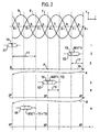
- Fig. 2 shows a time diagram for illustrating the operation of the wiring phase detection system shown in Fig. 1 according to an embodiment of the present invention.
- Fig. 2 shows the three phase voltages R, S and T over time.
- the three phase voltages are sign waves with the phase voltage S being 120° behind the phase voltage R, and the phase voltage T being 120° behind the phase voltage S and thus 120° ahead of the phase voltage R.
- Each of the three phase voltages have two zero crossings per cycle, that is one zero crossing per cycle with a specified slope.
- the zero crossings with a positive slope are denoted R+, S+ and T+, respectively, while zero crossings with a negative slope are denoted with R-, S- and T-, respectively.
- Fig. 2 the horizontal axis t denotes the time axis, while the dashed lines in the vertical direction Y in Fig. 2 correlate various events shown in Fig. 2 with certain points of the phase voltages R, S and T, as will be explained in detail in the following.
- the arrows A and B in Fig. 2 indicate that for reasons of space on the drawing sheet, the time axis has been drawn in three portions one above the other. The two points connected by the arrow A are actually coincident on the time axis. The same applies for the two points connected by the error B.
- P denotes the alternating voltage period in the three phase voltages R, S and T which is 20 ms in case of a 50 Hz system.
- the numerals 1 to 4 in the right hand portion of Fig. 2 refer to the nodes 1 to 4 in Fig. 1 to indicate the location where the respective events depicted in Fig. 2 take place.
- the node 1 connected to the reference phase R sends a message S1 with a time stamp TS therein essentially coinciding with a zero crossing R+ of the reference phase R.
- the embodiment shown in Fig. 1 uses power line communication to transmit this time stamp TS in the message S1 of node 1 to the relay node 2.
- the relay node 2 receives the message S1 with the time stamp TS and measures a time interval, denoted T1 in Fig. 2 , between the received time stamp TS in the message S1 and the occurrence of a reference point T+ in the arbitrary phase voltage T to which the node 2 is connected.
- the node 2 then takes the measured time interval T1 to generate a message M1(T1) which contains the information about a phase relation between the received time stamp signal TS in the message S1 and the wiring phase of the node 2.
- the node 2 generates a message S2 which contains a time stamp signal TS coinciding with the occurrence of another reference point T+ in the phase voltage of the wiring phase T of node 2.
- the message S2 generated and transmitted by the node 2 via the power line L furthermore comprises the phase relation information message M1(T1).
- the message S2 is received at the relay node 3, and the relay node 3 then measures a time interval, denoted T2 in Fig. 2 , between the received time stamp TS in the message S2 from the node 2, and the occurrence of a reference point R+ in the phase voltage to which the node 3 is connected.
- T2 a time interval
- the time interval T2 reaches from T+ to R+.
- phase relation information M1(T1) contained in the message S2 and the measured time interval T2 is suitably combined to obtain combined phase relation information as will be exemplified in more detail below.
- Node 3 then generates a message S3 which comprises a time stamp TS as well as the combined phase relation information M2(T1+T2).
- This message S3 is transmitted by the node 3 via the power line L at a timing such that the time stamp TS coincides with a subsequent reference point R+ on the phase voltage R to which the node 3 is connected in the embodiment shown.
- the message S3 containing the time stamp TS is received, and the node 4 measures a time interval, denoted T3 in Fig. 2 , between the time stamp TS in the message S3 and a reference point S+ in the phase voltage S to which the node 4 is connected.
- the combined phase relation information M2(T1+T2) in the message S2 and the time interval T3 is sufficient for node 4 to determine is wiring phase relative to the wiring phase of the reference node 1.
- Node 4 can determine its relative wiring phase by combining the phase relation information M2(T1+T2) in the received message S3 and the measured time interval T3.
- Node 4 may then generate a return message S4 which contains a message M3(T1+T2+T3) with the phase relation information thus combined.
- This message S4 may be relayed via the nodes 3 and 2 back to the node 1 to inform the node 1 about the wiring phase of the node 4.
- the phase relation information obtained for measuring the respective time intervals T1, T2 and T3 is preferably expressed in terms of an integer obtained by mapping the measured time interval T1, T2 and T3, respectively, onto one of N integers, N being the number of wiring phase possibilities to be distinguished in the wiring phase detection.
- This mapping operation corresponds to dividing the measured time interval by P/N.
- the integers obtained by this mapping operation are a suitable representation of phase relation information.
- phase relation information can advantageously take place simply by adding these integers, and most preferably by means of a modulo N addition.
- the message M1(T1) will carry the integer 2.
- the operation 0 + 1 mod 3 performed at node 4 will then reveal that node 4 is one phase behind the reference phase, that is node 4 is connected to the phase voltage S. Accordingly, the message M3 transmitted back to the reference node 1 simply contains the integer 1.
- phase relation information is a particularly advantageous implementation in terms of computational complexity
- other representations would include the explicit time intervals in terms of seconds or in terms of phase angle or any other suitable representation.
- the message portions M1, M2 and M3 and the time stamp TS are respectively integrated into a single message S1, S2, S3 and S4.
- the message S1 shown in Fig. 2 does not comprise a message portion, because this message has been generated by the reference node and need not carry any additional phase relation information. Nevertheless, in order to obtain a unified communication protocol, it may be advantageous to provide also the message S1 with a message portion which may contain dummy information.
- the message S4 is shown in Fig. 2 without a time stamp signal, because this message serves to report the combined phase relation information obtained at node 4 back to the reference node 1 for which a specified timing is not required. Nevertheless, again for the sake of a unified communication protocol it may be advantageous to build the message S4 with a time stamp similar to the other messages, and to transmit the message S4 such that its time stamp coincides with a reference point in the wiring phase of the node S4.
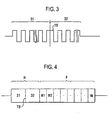
- Fig. 3 shows an embodiment of a time stamp signal.
- the signal shown in Fig. 3 consists of first portion 31 and a second portion 32.
- the first portion 31 comprises an alternating signal pattern at a specified frequency.
- the portion 32 comprises a signal pattern at the same specified frequency, however, with an inverse phase relative to the phase of the signal pattern 31.
- the phase discontinuity between the first portion 31 and the second portion 32 constitutes the time stamp TS.
- Fig. 4 shows an embodiment of a message signal which integrates a time stamp signal and a message portion.
- reference numeral 31 and 32 denote the signal sections described above with reference to Fig. 3 .
- TS denotes a time stamp in the form of a phase discontinuity between the signal portions 31 and 32.
- the two signal portions 31 and 32 constitute a header H which is useful for establishing bit synchronization.
- Reference character F in Fig. 4 denotes a message field.
- the message field F may comprise a plurality of message sub fields N1, N2, ..., Ni.
- the messages S1 to S4 shown in Fig. 2 are structured in accordance with the embodiment of Fig. 4 .
- Each of the message fields N1 to Ni comprises phase relation information as described in connection with Fig. 2 , and furthermore the address of the node where this phase relation information has been obtained as described above, that is by combining received phase relation information and a measured time interval.
- each node that receives phase relation information and combines the received phase relation information with information obtained from measuring a time interval between the time stamp and a reference point on its wiring phase appends the combined phase relation information thus obtained together with its own node address to the message that it relays to the next node.
- the message S4 in Fig. 2 from the node 4 back to the node 1 in Fig. 1 comprises phase relation information that allows the node 1 to obtain the wiring phase of all the nodes involved in the wiring phase detection of node 4.
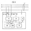
- Fig. 5 shows a block diagram of a node forming part of the system shown in Fig. 1 .
- the reference characters R, S, T and N denote the three phases and neutral, respectively, of the power line L, as explained before.
- the node shown may be connected to one or all of the three phases.
- TR denotes a transceiver circuit for establishing power line communication via the power line L.
- CCT, CCS and CCR denote coupling capacitors, which allow the transceiver circuit TR to transmit and receive power line communication signals from those phases of the power line L to which the node is connected.
- inductive coupling means may be used for this purpose, for example coupling transformers, as is well known as such.
- Power line communication signals may be injected into and extracted from one conductor only or into/from more or all conductors of the power line, on each phase with a separate transceiver front end or with a single transceiver front end for all lines in parallel.
- ZD denotes a reference point detector, for example a zero crossing detector circuit which is connected to detect zero crossings at a specified one of the three phases R, S and T to which the node shown in Fig. 5 is connected.
- the specified phase is that phase of the node the wiring of which is to be detected.
- MC denotes a micro controller circuit.
- MEM denotes a memory section
- TM denotes a timer circuit.
- IF denotes an interface circuit for interfacing the node shown in Fig.
- B denotes a bus for exchanging data and address information between the micro controller unit MC, the memory section MEM, the transceiver circuit TR, the zero crossing detector ZD, the timer TM and the interface circuit IF.
- IRQ denotes an interrupt request line to notify the micro controller unit MC of interrupts generated by the transceiver circuit TR and the zero detector circuit ZD, respectively, as will be explained in the following.
- the node sown in Fig. 5 operates under software control in accordance with program data stored in the memory section MEM to perform operations as described above with reference to Fig. 2 . If the node of Fig. 5 is controlled to act as the node 1 at the reference location, that phase to which the input IN1 of the zero crossing detector ZD is connected, will be the reference phase for performing the wiring phase detection, that is phase R in Fig. 5 . Whenever the zero crossing detector ZD detects a zero crossing with positive slope, ZD generates an interrupt request on the line IRQ for the micro controller MC and places information on the bus B that a zero crossing with a specified slope has occurred.
- the micro controller will read information from bus B concerning the source of the interrupt and then instruct the transceiver circuit TR to place a predetermined signal pattern on the power line L which contains a time stamp, e.g. as explained above in connection with Fig. 3 or Fig. 4 .
- the node at the reference location 1 preferably also transmits a message which contains an address of the remote node 4 the phase wiring of which is to be detected.
- each message transmitted by a node contains not only the remote node address but a list of node addresses of all nodes involved in the detection of the wiring phase of the remote node 4 as well as an address pointer field which contains the address of the respective next node to which the message is to be addressed.
- Each node contained in the list updates the address pointer field in accordance with the entries in the list of node addresses to achieve that the relay messages follow a sequence of nodes defined in the node address list.
- the transceiver circuit TR will listen to communication on the power line L. Whenever the transceiver circuit TR receives a message addressed to its own node, it will perform the necessary demodulation and decoding steps, inform the micro controller MC about the reception of a new message and place the received data on the bus B. If the micro controller MC identifies the message to be a return message S4 from a remote node the phase wiring of which is to be detected, the micro controller MC will evaluate the information contained in the received message in accordance with the operations described above to obtain the phase wiring of the remote node, and store the result in the memory section MEM.
- the transceiver circuit TR receives such a message, informs the micro controller MC via an interrupt request of the received message and places its content on the data bus B as before.
- the micro controller MC evaluates the address and message content to determine whether the message has to be relayed to another node. If so, it then instructs the timer TM to begin a time measuring operation.
- a further interrupt request is generated to the micro controller, this time by the zero crossing detector, and in response to this interrupt request the micro controller will then stop the time measuring operation of the timer circuit TM and suitably process the data concerning the time interval measured by the timer circuit TM in accordance with the principles described above.
- the time information thus obtained and phase relation information extracted from the received message are then combined under program control by the micro controller MC, and a new message is assembled by the micro controller MC which contains the resulting combined phase relation information. This message is made available to the transceiver circuit TR through the data bus B.
- the micro controller MC then instructs the transceiver circuit TR to generate and transmit a message that contains a time stamp and the combined phase relation information as well as the address of that node the wiring phase of which is to be detected, which address was contained in the previously received message.
- the message also contains said list of addresses of said address pointer field that was updated by the node to indicate the address of the next node for the message.
- the micro controller MC extracts the phase relation information contained in the received message and measures the time between the time stamp in the received message and the occurrence of a reference point in the phase to which the zero crossing detector ZD is connected, according to the same principles as described before, using the timer circuit TM. The result of this time interval measurement is then combined by the micro controller MC with the phase relation information in the received message. The combined phase relation information thus obtained is then included by the micro controller in a return message generated by the transceiver circuit TR to inform the reference node about the phase wiring of the present node relative to the reference phase of the requesting node.
- each of the nodes 1 to 4 has essentially the same configuration and operates under software control by virtue of a micro controller in accordance with the message content it has received.
- At least one node is adapted to generate a wiring phase detection request message addressed to a specified remote node, as described. Any node involved in the relay process that receives a wiring phase detection request message not for itself but for a different node, will take the received message and perform a relay operation as described before.
- a node that receives a wiring phase detection request message for itself will perform the operations as described to return a message to the requesting node where the wiring phase detection request message originated in order to inform that node about its own wiring phase relative to the wiring phase of the requesting node.
- a time offset may occur between the zero crossing and the time stamp.
- a simple solution to compensate the delay between the zero crossing and the associated time stamp is, to add to each measured time interval the known offset.
- Fig. 6A shows an embodiment of a time stamp detector circuit for detecting a time stamp signal shown in Fig. 3 .
- the time stamp detector circuit of Fig. 6A may be a part of the transceiver circuit TR in Fig. 5 .
- IN2 denotes the input of the time stamp detector circuit. This input is connected to receive an input signal from the receiver and demodulator (not shown) of the transceiver circuit TR in Fig. 5 .
- R1 and R2 denote two resistors connected to constitute a voltage divider.
- A denotes an operational amplifier or comparator the positive input of which is connected to the output of the voltage divider R1, R2 and the negative input of which is connected to ground.
- C1 and R3 denote a capacitor and a resistor, respectively, which are connected to differentiate an output signal at the negative output of the operational amplifier A.
- C2 and R4 denote a differentiator which is connected to differentiate an output signal at the positive output of the amplifier A.
- D1 denotes a diode connected in parallel with the resistor R3 such that the cathode of this diode is connected to the capacitor C1 while the anode is connected to ground.
- D3 denotes a diode which is connected in parallel to the resistor R4 such that the cathode of diode D3 is connected with the capacitor C2 while the anode of diode D3 is connected to ground.
- the cathode of diode D1 is connected with the resistor R5 through a further diode D2.
- the cathode of diode D3 is connected to the same node of the resistor R5 through a diode D4.
- This node of the resistor R5 is connected with the input of a retriggerable monoflop MF.
- the other output of the resistor R5 is connected to ground.
- the output of this monoflop constitutes the output OUT of the time stamp detector circuit.
- the retriggerable monoflop has a time period of about 1.5 times the duration between two regular consecutive edges of the signal section 31 shown in Fig. 4 .
- Fig. 6B illustrates the operation of the time stamp detector of Fig. 6A .
- the upper diagram in Fig. 6B shows the voltage wave form at the input IN2 of the time stamp detector.
- the operational amplifier A converts this input signal into complementary digital signals at its positive and negative outputs.
- the differentiator and the subsequent diode network connected to the respective outputs emphasize only the positive edges in the output signals of the respective outputs.
- These differentiated and rectified signals are combined at the resistor R5, this leading to an output signal across the resistor R5 as shown in the middle of Fig. 6B .
- the signal across resistor R5 triggers the retriggerable monoflop which will maintain its triggered state as long as the pulses across R5 are regularly spaced, as shown.
- a pulse across R5 will be missing such that the monoflop MF will fall back into the reset state and thus generate a detection signal at the output OUT.
- a time stamp detector circuit may be based on integrating the signal at the input IN2 and comparing the integrated signal with a threshold that will be reached when the duration of a signal segment of constant amplitude is longer than usual, i.e. when the phase inversion occurs.
- Other alternatives of detecting the time stamp signal according to the embodiment of Fig. 3 may adopt a digital signal pattern detector or any other suitable circuit known per se.
- the zero crossing detector ZD may be implemented in a variety of ways well known as such.
- a suitable implementation of the zero crossing detector ZD comprises a circuit having a comparator, a differentiator and a rectifier connected to its output; essentially similar to the capacitor, resistor and diode network connected to one of the two outputs of the comparator A shown in Fig. 6A .
- the present invention is not limited to the particular phase relation detection mechanisms herein described.
- a person skilled in the art will appreciate that any phase relation detection mechanism which provides phase relation information between two consecutive locations, can be employed in the wiring phase detection according to the present invention.
- the invention is not limited to the time stamp signal herein described or to a particular time stamp detection circuit. It has to be emphasized that the circuits and signals shown merely serve the purpose of illustrating particular embodiments of the present invention. Reference signs in the claims serve to increase their intelligibility. They shall not be construed as limiting the claims.
Abstract
Description
- The present invention relates to a method and an apparatus for detecting the wiring phase of an unknown phase voltage relative to a reference phase voltage in an electrical power distribution system having a poly phase power line.
- Modern power distribution systems use poly phase power lines for distributing electricity. A poly phase power line comprises a plurality, typically three, conductors, each conductor carrying a specified phase voltage. As is well known, a poly phase power line may or may not have a neutral conductor which, if present, constitutes an additional conductor of the poly phase power line. Moreover, in addition to these conductors of a typical poly phase power line, there may or may not be a further conductor which carries the ground potential.
- While a poly phase power line offers many advantages for certain types of loads, e.g. electrical machines employing rotating magnetic fields, there are many electrical consumers which are not connected to all the phases available in a given poly phase power line. For many types of loads it is sufficient that the load is connected between two of the phases, or more typical, between one of the available phases and the neutral conductor. This wiring scheme is widely spread particularly in the low voltage networks used for supplying consumer appliances with electricity in the domestic domain. In Europe, the low voltage power distribution network has three wiring phases, each at a voltage of 220 Volt to 240 Volt to neutral, the three phases being spaced apart at an angle of 120 °. Particularly in the domestic domain, most electrical loads are connected between one of the three wiring phases R, S, T and the neutral conductor N, the particular phase R or S or T to which the load is actually connected, being insignificant for most types of single phase applications and loads, and therefore typically unknown.
- In some cases it is, however, desirable to detect the phase to which a given load is connected. For example, in a power line communication system that uses the existing power line distribution network for telecommunication purposes, it may be highly desirable for the transmitter to know the phase voltage to which the receiver is connected, because it may be expected that the communication between the transmitter and the receiver via a power line is better if the transmitter and the receiver are connected to the same phase voltage than if the transmitter and the receiver communicates with each other across different phases through capacitive or inductive cross talk between the phases.
- In an electricity metering system for metering the electric energy consumed by a plurality of consumers, there are good reasons to detect the wiring phase of an electricity meter located inside or outside of the consumer premises. For example, the detection of the wiring phase allows to judge whether a consumer has unlawfully rewired the electricity meter in order to prevent the meter from correctly measuring the consumed energy. If the meters communicate with other nodes in a remote metering system through power line communication, the knowledge of the phase to which the respective remote meters at the consumer premises are connected, is valuable information for optimising the communication performance of the remote metering system as a whole.
- From
US 4,626,622 it is known to identify an unknown phase within a poly phase network by comparison of the unknown phase with a known reference phase of the poly phase network. The system comprises a first device connected to the reference phase and a second device connected to the unknown phase at another location. The first and second devices each comprise a modem for establishing a telephone connection between the two devices. The first device includes circuitry to produce a digital signal representative of the alternating voltage of the reference phase. This representative signal is transmitted through the two modems and the telephone connection from the first to the second device. The second device includes a phase detection circuit for identifying the unknown phase by detecting the phase angle between the alternating voltage of the reference phase and the alternating voltage of the unknown phase. - While the method and system known from this document is suitable to carry out the identification of the unknown phase when the reference location of known wiring phase at a point of the poly phase network, e.g. the outlets of a substation transformer, is far from the location where the phase is unknown, this method and system has the drawback that a separate telephone connection between the first and the second devices is required. In many cases, a separate telephone connection is not available.
- The IEC 61334-5-2 defines a method for identifying an unknown phase within a poly phase network by means of injecting a short data packet or time stamp signal into the poly phase network when a first reference point, e.g. a zero crossing, occurs in the reference phase voltage. The poly phase network itself serves to communicate the short data packet or time stamp signal to the location where the unknown phase has to be identified. At the location of the unknown phase, the short data packet or time stamp signal is extracted from the poly phase power line, and a time interval between the occurrence of the short data packet or time stamp signal and a reference point, e.g. a zero crossing in the unknown phase voltage is measured. That time interval is then indicative of the phase angle between the reference phase and the unknown phase. The phase angle thus determined allows to identify the unknown phase wiring.
- While the phase identification method defined in this standard does not require a separate telephone line between the location of known phase and the location of unknown phase, this method suffers from the drawback that power line communication generally has a limited range only. The electrical characteristics of power lines are not ideally suited for transmitting communication signals. Moreover, many electrical loads connected to power lines tend to generate a significant noise floor such that already at moderate distances from the location of the transmitter, the signal to noise ratio for detecting the short data packet or time stamp signal becomes unacceptably low. This limits the use of the phase detection method according to the IEC standard.
- A method for detecting the wiring phase at a remote location relative to a reference wiring phase at a reference location according to the preamble of
claim 1 is known fromUS 5,617,329 . According to this document, the central station combines the phase of the relay station and the phase of the meter relative to the relay station to determine the absolute phase of the meter. - Accordingly, it is an object of the present invention, to provide a method and apparatus for detecting the wiring phase of an unknown phase voltage relative to a reference phase voltage in an electrical poly phase power distribution system, which method and device allow to detect the wiring phase even if the location of unknown wiring phase is at a larger distance from the known reference phase and a direct communication channel connecting the location of known phase and the location of unknown wiring phase is not available.
- This object is solved in accordance with the present invention as defined in the independent patent claims. Advantageous embodiments of the present invention are given in the dependent claims.
- According to an embodiment of the present invention, in order to detect the wiring phase of an unknown phase voltage at a remote location relative to a reference phase voltage (R) at a reference location in an electrical power distribution system having a single phase or poly phase power line (R, S, T, N), at least one relay location to relay signals between said reference location and said remote location is arranged between said reference location and said remote location and connected to a wiring phase of the poly phase power line. A first phase relation is detected between the reference wiring phase at the reference location and the wiring phase at a said relay location. Moreover, a second phase relation is detected between the wiring phase at the relay location and the wiring phase at the remote location. Based on the first and second phase relation the wiring phase of the remote location relative to the reference wiring phase may be obtained.
- According to the invention, the detected first phase relation is transmitted from the relay location towards the remote location.
- The first phase relation can be obtained in a number of different ways. If a new node at a remote location is newly added to extend an existing network, a previously existing node of the network may take the function of a relay location for which the wiring phase is already known from a previous detection. In this case it is sufficient that the relay location performs the detection of the second phase relation between the wiring phase at the relay location and the newly added remote location. The wiring phase at the remote location can then be determined at the remote location or at the relay location on the basis of the second phase relation thus detected and the already known wiring phase of the relay location, or the relay location transmits the detected second phase relation to the reference location where the wiring phase of the remote location may be determined using the knowledge of the wiring phase of the relay location.
- If the at least one relay locations between the reference location and the remote location have unknown arbitrary wiring phases, it may be advantageous to detect a first phase relation between the wiring phase at the reference location and the wiring phase at the relay location, and transmit it toward said remote location. A second phase relation between said relay location and said remote location is detected. Based on said first phase relation and said second phase relation, the wiring phase at said remote location relative to the wiring phase at the reference location can be detected.
- Advantageously, the locations may be nodes of a network using the power line as a communication signal transmission medium.
- According to an embodiment of the present invention, the wiring phase of an unknown phase voltage relative to a reference phase voltage in an electrical power distribution system having a single phase or poly phase power line is detected by transmitting from a reference location a first time stamp signal when a first reference point in the reference phase voltage occurs. The first time stamp signal is received at a relay location where a first time interval is measured between the occurrence of the first time stamp signal and the occurrence of a reference point in a first arbitrary wiring phase of the power line, to obtain first phase relation information indicative of a phase relation between the reference phase voltage and the first arbitrary phase voltage. From the relay location a relay message is transmitted which comprises this phase relation information. Moreover, from the relay location a relay time stamp signal is transmitted when a second reference point in the first arbitrary phase voltage occurs.
- According to this embodiment of the present invention, the generation of a relay time stamp signal together with a relay message comprising said phase relation information allows to relay at the relay location the reference phase information to a remote location, without there being a need for a direct communication channel between the reference location and the remote location.
- The relay location may be followed by additional relay locations to bridge even larger distances between the reference location and the remote location. Advantageously, a further relay at a third location receives the relay time stamp signal and the relay message from the preceding relay location and measures a second time interval between the occurrence of the relay time stamp signal and the occurrence of a reference point in a second arbitrary phase voltage at the third location to obtain second phase relation information indicative of a phase relation between the wiring phase voltages at the consecutive relay locations. At the third location, the second phase relation information and the first phase relation information that was received from the preceding relay location, is then combined. The combined phase relation information is indicative of the phase relation between the reference phase voltage and the wiring phase voltage at the third location. This information can be transmitted to the further location in the form of a further relay message, or this information can be used to determine the unknown wiring phase at the third location.
- The term 'reference location' may refer to a location or node where the wiring phase of the power line is known, be it simply by definition, as would be the case at the outlet of a three phase transformer. The term remote location then refers to a location or node where the wiring phase is unknown. It has to be noted, however, that in the alternative, the term 'reference location' may also refer to a location or node where the wiring phase is unknown and the term 'remote location' refers to a location or node where the wiring phase is known. In the embodiment described above, the combined phase relation between adjacent locations is taken along to the remote location. It does not make a principal difference for detecting an unknown wiring phase whether this phase relation is taken along in the direction from the location with the known wiring phase to the location with the unknown wiring phase or in the opposite direction. In the former case the information required to determine the unknown wiring phase is available at the location of unknown wiring phase, while in the latter case this information is available at the location of known wiring phase.
- The phase relation information can be represented in terms of time, in terms of phase angles or in terms of 'hops' between consecutive phases to be distinguished in the phase diagram which describes the polyphase system. In a three phase system each hop would correspond to a phase angle of 120°. If there is a need to also detect reverse wiring, then in a three phase system there would be six different wiring possibilities to be distinguished, and each hop would correspond to 60° because in this case there are three normal phases plus another three reverse phases to be considered.
- The phase relation information in a received relay message and the phase relation information obtained from measuring the time interval between the received time stamp signal and a reference point in a wiring phase voltage at the receiver location can be combined in a variety of ways, and preferably by simply adding the respective time intervals, associated phase angle values or number of hops. This addition may advantageously be a modulo M addition. If the phase relation information is represented in terms of time, then M denotes the period of the alternating voltage carried on the poly phase power line. If the phase relation information is represented in terms of phase angles, M denotes the phase angle value associated with a full cycle, that is 2n or 360°. If the phase relation information is represented in terms of a number of hops between the phases, then M denotes the number of wiring phase possibilities to be distinguished in the poly phase system.
- Preferably, the time interval between the occurrence of a time stamp signal and the occurrence of a reference point is measured redundantly in order to increase the reliability of the final measurement result. Preferably, for measuring a particular time interval, the transmitter transmits more than one time stamp signals, each time stamp signal being synchronized with a reference point in the phase voltage of the transmitter. This enables the receiver to repeat the measurement of the time interval between the time stamp signal and the occurrence of a reference point in the phase voltage of the receiver in order to decide the measured time interval based on a majority vote, and/or to inform the transmitter of a time interval measurement failure if a clear majority vote is not achieved.
- Advantageously, the same relays which relay the time stamp signal and phase relation information, may be used to relay a return message from the remote location of unknown phase wiring to the reference phase location in order to inform the reference phase location of the detected wiring phase at the remote location.
- Preferably, the respective reference points in the reference phase and in the arbitrary wiring phases at the respective relay location(s) and remote location are predetermined repetitive events which occur with a period T which is the alternating voltage period of the poly phase power distribution network, e.g. 20ms in case of a 50Hz system. Zero crossings of the respective phase voltages with a slope of specified sign are particularly suitable as reference points.
- A time stamp signal may be a short burst or any kind of suitable data packet or symbol sequence that is short in comparison with the phase voltage period T divided by the number of wiring phase possibilities to be distinguished. The time stamp signal can also be a phase discontinuity and/or an amplitude discontinuity in a more complex signal, bit sequence or message signal.
- Preferably, in a poly phase system with an odd number N of phases, the phase relation information is mapped onto 2N different wiring phases, for example at a spacing of 60° if N = 3, in order to take account of the possibility that at a relay location or at the remote location with the unknown phase wiring, a particular phase may be connected with reversed polarity. This feature may be particularly useful in remote electricity metering applications in order to detect a wiring error or unlawful rewiring of the remote meter at the consumer premises.
- The time stamp signals and messages generated at the various locations may preferably be transmitted from one location to the next by means of power line communication, or by means of any other communication technology which offers a communication range sufficient to bridge the distance to the next relay location, for example optical cable or radio communication. If power line communication is used for transmitting the time stamp signals and messages from one location to the next, these signals may be injected into all the N phases of the poly phase power line, or it may be sufficient to inject these signals into a single phase only, due to the rather strong capacitive and inductive coupling that exists in a typical poly phase power line between the various phases. In applications with a large number of available relay locations, e.g. in a remote electricity metering system with a considerable number of consumers connected to the same low voltage network section, blue tooth communication or any other limited range radio communication can be a suitable communication technology between the various consecutive locations up to the remote location the phase wiring of which is to be detected.
- The present invention also relates to an apparatus for performing or participating in a method according to the present invention. An embodiment of a relay apparatus for detecting the phase wiring of an arbitrary unknown phase voltage comprises a circuit for receiving a first time stamp signal, a circuit for measuring a time interval between the occurrence of said time stamp signal and the occurrence of a reference point in an arbitrary wiring phase voltage of said power line to obtain phase relation information indicative of a phase relation between said time stamp signal and said arbitrary phase voltage, a circuit for generating and transmitting a relay message which comprises said phase relation information, and a circuit for generating and transmitting a relay time stamp signal when a second reference point in said arbitrary phase voltage occurs. The relay apparatus according to this embodiment preferably also comprises a circuit for receiving phase relation information attributed to said first time stamp signal, which phase relation information may be in the form of a relay message from a relay apparatus at a preceding relay location. The circuit for generating a relay message then preferably combines the received phase relation and the phase relation information obtained from measuring the time interval, to generate the relay message such that it comprises the combined phase relation information.
- According to a further embodiment of the present invention, an apparatus for detecting the phase wiring of an arbitrary unknown phase voltage comprises a circuit for receiving a time stamp signal, a circuit for measuring a time interval between the occurrence of the time stamp signal and the occurrence of a reference point in said arbitrary unknown wiring phase voltage to obtain phase relation information indicative of a phase relation between said time stamp signal and said arbitrary unknown phase voltage, a circuit for receiving a relay message comprising phase relation information indicative of a phase relation between the reference phase and the time stamp signal, and a circuit for combining the phase relation information indicative of a phase relation between the time stamp signal and said arbitrary unknown phase voltage and said received phase relation information, as well as a circuit for determining the phase wiring of said unknown arbitrary phase voltage from said combined phase relation information. An apparatus according to this embodiment of the present information is able to communicate with a preceding relay location in order to determine the phase wiring of the unknown arbitrary phase voltage at the location of the apparatus.
- A particularly advantageous application of the.present invention resides in the field of remote metering the consumption of electricity distributed to a large number of consumers through a public electricity distribution system. A remote metering system of this kind may comprise a concentrator located e.g. at a secondary substation for transforming the voltage carried on the medium voltage distribution network, e.g. 20 kV, into a low voltage, e.g. 230 V. The secondary sub station feeds a low voltage polyphase network to which a plurality of consumers is connected. Each consumer has an electricity meter capable of communicating with the concentrator of the network section to which it is connected. In order to assist the concentrator in detecting the wiring phase of the remote meters connected to its low voltage network section, each remote meter preferably comprises a relay apparatus according to the present invention and/or an apparatus for detecting the phase wiring of an arbitrary unknown phase voltage according to the present invention.
- In the following, advantageous embodiments of the present invention will be described with reference to the accompanying drawings. The following description serves to illustrate particular embodiments of the present invention which shall, however, not be construed to limit the present invention.
- Fig. 1
- shows the outline of a system for detecting the wiring phase of an unknown phase voltage in an electrical power distribution system according to the present invention;
- Fig. 2
- shows a time diagram for illustrating the operation of the wiring phase detection system shown in
Fig. 1 according to an embodiment of the present invention; - Fig. 3
- shows an embodiment of a time stamp signal;
- Fig. 4
- shows a message signal comprising a time stamp signal and a message portion;
- Fig. 5
- shows a block diagram of a node forming part of the system shown in
Fig. 1 ; - Fig. 6A
- shows an embodiment of a circuit for detecting time stamps in a phase voltage;
- Fig. 6B
- is a timing diagram illustrating the operation of the circuit shown in
Fig. 6A . -
Fig. 1 shows the outline of a system for detecting the wiring phase of an unknown phase voltage in an electrical power distribution system according to the present invention. InFig. 1 , L denotes a poly phase power line as a part of an electrical power distribution system. The poly phase power line L inFig. 1 is a three phase power line having three phases denoted as R, S and T, as well as a neutral conductor N. Between any two of the three phases R, S and T there is a phase shift of 120°, as is well known for three phase power distribution systems. PC inFig. 1 denotes parasitic distributed coupling capacitances between the three phases R, S and T of the poly phase power line L. -
Reference numeral 1 denotes a node connected to the power line L at a first location. In the embodiment ofFig. 1 , thenode 1 is connected to all the three phases R, S and T as well as to the neutral conductor N of the power line L in order to be able to inject and extract power line communication signals into and from the power line L, although due to the parasitic capacitive coupling between the three phases it would be sufficient to connect thenode 1 to less than all the three phases. Thenode 1 uses one of the three phases R, S and T as a reference phase. Any one of the available phases R, S and T may be chosen atnode 1 as a reference phase. Without any loss of generality it may be assumed that R denotes the reference phase in the wiring phase detection system shown inFig. 1 . -
Reference numerals Fig. 1 denote relay nodes connected to arbitrary, a priori unknown phases of the poly phase power line L. In the example shown inFig. 1 ,relay node 2 is connected between phase T and neutral N, whilerelay node 3 is connected between phase R and neutral N. The wiring phase of these relay nodes is arbitrary in the sense that any of the available phases of the power line L may be used, without a need to know in advance which of the phases the node is connected to. It has to be noted that although a poly phase power line is shown in this embodiment, the present invention is not limited to wiring phase detection for poly phase power lines. In case of a single phase power line it may be interesting to detect reverse wiring of a consumer at a remote location. The present invention is also applicable to single phase systems. -
Reference numeral 4 denotes a node connected to an unknown arbitrary phase of the poly phase power line L. Thenode 4 may be any kind of apparatus or circuit for which the information is of interest to which of the three phases R, S and T it is connected. As an example, thenode 4 may be a single phase or poly phase electricity meter for which it is desired to detect its wiring phase(s) relative to the reference phase R, e.g. in order to be able to detect errors or fraud in the way the meter is connected to the poly phase power line L, and/or in order to use theremote meter 4 as a node in power line communication applications like remote metering of electricity in an optimised way. - In the embodiment shown in
Fig. 1 , there is no need for a direct communication channel between the reference location ofnode 1 and the remote location of thenode 4 the wiring phase of which is to be detected. In order to be able to perform this detection, thenodes Fig. 1 will be explained in the following making reference toFig. 2 . -
Fig. 2 shows a time diagram for illustrating the operation of the wiring phase detection system shown inFig. 1 according to an embodiment of the present invention. - The upper portion of
Fig. 2 shows the three phase voltages R, S and T over time. As shown, the three phase voltages are sign waves with the phase voltage S being 120° behind the phase voltage R, and the phase voltage T being 120° behind the phase voltage S and thus 120° ahead of the phase voltage R. Each of the three phase voltages have two zero crossings per cycle, that is one zero crossing per cycle with a specified slope. In the diagram ofFig. 2 , the zero crossings with a positive slope are denoted R+, S+ and T+, respectively, while zero crossings with a negative slope are denoted with R-, S- and T-, respectively. In the embodiment shown, zero crossings with a positive slope in the respective phase voltages R, S and T have been chosen to serve as reference points of the respective phase voltages. InFig. 2 , the horizontal axis t denotes the time axis, while the dashed lines in the vertical direction Y inFig. 2 correlate various events shown inFig. 2 with certain points of the phase voltages R, S and T, as will be explained in detail in the following. The arrows A and B inFig. 2 indicate that for reasons of space on the drawing sheet, the time axis has been drawn in three portions one above the other. The two points connected by the arrow A are actually coincident on the time axis. The same applies for the two points connected by the error B. P denotes the alternating voltage period in the three phase voltages R, S and T which is 20 ms in case of a 50 Hz system. Thenumerals 1 to 4 in the right hand portion ofFig. 2 refer to thenodes 1 to 4 inFig. 1 to indicate the location where the respective events depicted inFig. 2 take place. - In order to perform the detection of the wiring phase of
node 4 inFig. 2 , thenode 1 connected to the reference phase R sends a message S1 with a time stamp TS therein essentially coinciding with a zero crossing R+ of the reference phase R. The embodiment shown inFig. 1 uses power line communication to transmit this time stamp TS in the message S1 ofnode 1 to therelay node 2. Therelay node 2 receives the message S1 with the time stamp TS and measures a time interval, denoted T1 inFig. 2 , between the received time stamp TS in the message S1 and the occurrence of a reference point T+ in the arbitrary phase voltage T to which thenode 2 is connected. Thenode 2 then takes the measured time interval T1 to generate a message M1(T1) which contains the information about a phase relation between the received time stamp signal TS in the message S1 and the wiring phase of thenode 2. Thenode 2 generates a message S2 which contains a time stamp signal TS coinciding with the occurrence of another reference point T+ in the phase voltage of the wiring phase T ofnode 2. The message S2 generated and transmitted by thenode 2 via the power line L furthermore comprises the phase relation information message M1(T1). - The message S2 is received at the
relay node 3, and therelay node 3 then measures a time interval, denoted T2 inFig. 2 , between the received time stamp TS in the message S2 from thenode 2, and the occurrence of a reference point R+ in the phase voltage to which thenode 3 is connected. In this example the time interval T2 reaches from T+ to R+. - At
node 3, the phase relation information M1(T1) contained in the message S2 and the measured time interval T2 is suitably combined to obtain combined phase relation information as will be exemplified in more detail below.Node 3 then generates a message S3 which comprises a time stamp TS as well as the combined phase relation information M2(T1+T2). This message S3 is transmitted by thenode 3 via the power line L at a timing such that the time stamp TS coincides with a subsequent reference point R+ on the phase voltage R to which thenode 3 is connected in the embodiment shown. - At the
node 4, the message S3 containing the time stamp TS is received, and thenode 4 measures a time interval, denoted T3 inFig. 2 , between the time stamp TS in the message S3 and a reference point S+ in the phase voltage S to which thenode 4 is connected. The combined phase relation information M2(T1+T2) in the message S2 and the time interval T3 is sufficient fornode 4 to determine is wiring phase relative to the wiring phase of thereference node 1.Node 4 can determine its relative wiring phase by combining the phase relation information M2(T1+T2) in the received message S3 and the measured time interval T3.Node 4 may then generate a return message S4 which contains a message M3(T1+T2+T3) with the phase relation information thus combined. This message S4 may be relayed via thenodes node 1 to inform thenode 1 about the wiring phase of thenode 4. - In the embodiment shown, the phase relation information obtained for measuring the respective time intervals T1, T2 and T3 is preferably expressed in terms of an integer obtained by mapping the measured time interval T1, T2 and T3, respectively, onto one of N integers, N being the number of wiring phase possibilities to be distinguished in the wiring phase detection. This mapping operation corresponds to dividing the measured time interval by P/N. In the embodiment shown in
Fig. 2 , three wiring phase possibilities are considered, such that N = 3. Accordingly, in the depicted example T1 is mapped onto 2 (two), T2 is mapped onto 1 (one) and T3 is mapped onto 1 (one). The integers obtained by this mapping operation are a suitable representation of phase relation information. Combining the phase relation information can advantageously take place simply by adding these integers, and most preferably by means of a modulo N addition. In the embodiment shown inFig. 3 this will lead to the following result: The message M1(T1) will carry theinteger 2. The combined phase relation information carried in the message M2(T1+T2) is 2 + 1mod 3 = 0 which indicates that thenode 3 is connected.to the same wiring phase as the reference phase. The operation 0 + 1mod 3 performed atnode 4 will then reveal thatnode 4 is one phase behind the reference phase, that isnode 4 is connected to the phase voltage S. Accordingly, the message M3 transmitted back to thereference node 1 simply contains theinteger 1. - It has to be noted that while the integer representation of the phase relation information just described is a particularly advantageous implementation in terms of computational complexity, there are of course other possibilities to represent the phase relation information obtained from the measurement of the time intervals T1, T2 and T3. other representations would include the explicit time intervals in terms of seconds or in terms of phase angle or any other suitable representation. The exemplary embodiment in
Fig. 3 distinguishes between three wiring phases R, S and T. If inverse phase wirings are to be considered as additional wiring possibilities, then this will result in six different phases, i.e. N = 6. In this case, the reference points of the inverse phase voltages (not shown in the figure) will coincide with the points R-, S- and T- shown inFig. 2 . - In the embodiment of
Fig. 2 , the message portions M1, M2 and M3 and the time stamp TS are respectively integrated into a single message S1, S2, S3 and S4. Alternatively, it would be possible to transmit the time stamp signal TS and the associated message portion M1 in separate messages, there being no necessity to transmit the message portions M1 to M3 at a specified timing. - The message S1 shown in
Fig. 2 does not comprise a message portion, because this message has been generated by the reference node and need not carry any additional phase relation information. Nevertheless, in order to obtain a unified communication protocol, it may be advantageous to provide also the message S1 with a message portion which may contain dummy information. The message S4 is shown inFig. 2 without a time stamp signal, because this message serves to report the combined phase relation information obtained atnode 4 back to thereference node 1 for which a specified timing is not required. Nevertheless, again for the sake of a unified communication protocol it may be advantageous to build the message S4 with a time stamp similar to the other messages, and to transmit the message S4 such that its time stamp coincides with a reference point in the wiring phase of the node S4. -
Fig. 3 shows an embodiment of a time stamp signal. The signal shown inFig. 3 consists offirst portion 31 and asecond portion 32. Thefirst portion 31 comprises an alternating signal pattern at a specified frequency. Theportion 32 comprises a signal pattern at the same specified frequency, however, with an inverse phase relative to the phase of thesignal pattern 31. The phase discontinuity between thefirst portion 31 and thesecond portion 32 constitutes the time stamp TS. -
Fig. 4 shows an embodiment of a message signal which integrates a time stamp signal and a message portion. InFig. 4 ,reference numeral Fig. 3 . TS denotes a time stamp in the form of a phase discontinuity between thesignal portions signal portions Fig. 4 denotes a message field. The message field F may comprise a plurality of message sub fields N1, N2, ..., Ni. Advantageously, the messages S1 to S4 shown inFig. 2 are structured in accordance with the embodiment ofFig. 4 . Each of the message fields N1 to Ni comprises phase relation information as described in connection withFig. 2 , and furthermore the address of the node where this phase relation information has been obtained as described above, that is by combining received phase relation information and a measured time interval. Advantageously, each node that receives phase relation information and combines the received phase relation information with information obtained from measuring a time interval between the time stamp and a reference point on its wiring phase, appends the combined phase relation information thus obtained together with its own node address to the message that it relays to the next node. In this way, the message S4 inFig. 2 from thenode 4 back to thenode 1 inFig. 1 comprises phase relation information that allows thenode 1 to obtain the wiring phase of all the nodes involved in the wiring phase detection ofnode 4. -
Fig. 5 shows a block diagram of a node forming part of the system shown inFig. 1 . InFig. 5 the reference characters R, S, T and N denote the three phases and neutral, respectively, of the power line L, as explained before. The node shown may be connected to one or all of the three phases. TR denotes a transceiver circuit for establishing power line communication via the power line L. CCT, CCS and CCR denote coupling capacitors, which allow the transceiver circuit TR to transmit and receive power line communication signals from those phases of the power line L to which the node is connected. Of course, alternatively inductive coupling means may be used for this purpose, for example coupling transformers, as is well known as such. Power line communication signals may be injected into and extracted from one conductor only or into/from more or all conductors of the power line, on each phase with a separate transceiver front end or with a single transceiver front end for all lines in parallel. ZD denotes a reference point detector, for example a zero crossing detector circuit which is connected to detect zero crossings at a specified one of the three phases R, S and T to which the node shown inFig. 5 is connected. The specified phase is that phase of the node the wiring of which is to be detected. MC denotes a micro controller circuit. MEM denotes a memory section, and TM denotes a timer circuit. IF denotes an interface circuit for interfacing the node shown inFig. 5 with other circuitry not shown in the Figure, e.g. circuitry for metering the consumption of electricity or for performing any other function not directly related to the principles of the present invention. B denotes a bus for exchanging data and address information between the micro controller unit MC, the memory section MEM, the transceiver circuit TR, the zero crossing detector ZD, the timer TM and the interface circuit IF. IRQ denotes an interrupt request line to notify the micro controller unit MC of interrupts generated by the transceiver circuit TR and the zero detector circuit ZD, respectively, as will be explained in the following. - The node sown in
Fig. 5 operates under software control in accordance with program data stored in the memory section MEM to perform operations as described above with reference toFig. 2 . If the node ofFig. 5 is controlled to act as thenode 1 at the reference location, that phase to which the input IN1 of the zero crossing detector ZD is connected, will be the reference phase for performing the wiring phase detection, that is phase R inFig. 5 . Whenever the zero crossing detector ZD detects a zero crossing with positive slope, ZD generates an interrupt request on the line IRQ for the micro controller MC and places information on the bus B that a zero crossing with a specified slope has occurred. In response to the interrupt request, the micro controller will read information from bus B concerning the source of the interrupt and then instruct the transceiver circuit TR to place a predetermined signal pattern on the power line L which contains a time stamp, e.g. as explained above in connection withFig. 3 or Fig. 4 . The node at thereference location 1 preferably also transmits a message which contains an address of theremote node 4 the phase wiring of which is to be detected. Advantageously, each message transmitted by a node contains not only the remote node address but a list of node addresses of all nodes involved in the detection of the wiring phase of theremote node 4 as well as an address pointer field which contains the address of the respective next node to which the message is to be addressed. Each node contained in the list updates the address pointer field in accordance with the entries in the list of node addresses to achieve that the relay messages follow a sequence of nodes defined in the node address list. - The transceiver circuit TR will listen to communication on the power line L. Whenever the transceiver circuit TR receives a message addressed to its own node, it will perform the necessary demodulation and decoding steps, inform the micro controller MC about the reception of a new message and place the received data on the bus B. If the micro controller MC identifies the message to be a return message S4 from a remote node the phase wiring of which is to be detected, the micro controller MC will evaluate the information contained in the received message in accordance with the operations described above to obtain the phase wiring of the remote node, and store the result in the memory section MEM.
- If the node shown in
Fig. 5 receives a wiring phase detection message, the transceiver circuit TR receives such a message, informs the micro controller MC via an interrupt request of the received message and places its content on the data bus B as before. The micro controller MC evaluates the address and message content to determine whether the message has to be relayed to another node. If so, it then instructs the timer TM to begin a time measuring operation. At the occurrence of a reference point on the phase to which the zero detector circuit of the node is connected, a further interrupt request is generated to the micro controller, this time by the zero crossing detector, and in response to this interrupt request the micro controller will then stop the time measuring operation of the timer circuit TM and suitably process the data concerning the time interval measured by the timer circuit TM in accordance with the principles described above. The time information thus obtained and phase relation information extracted from the received message are then combined under program control by the micro controller MC, and a new message is assembled by the micro controller MC which contains the resulting combined phase relation information. This message is made available to the transceiver circuit TR through the data bus B. At the occurrence of a further reference point in the phase to which the zero crossing detector ZD is connected, the micro controller MC then instructs the transceiver circuit TR to generate and transmit a message that contains a time stamp and the combined phase relation information as well as the address of that node the wiring phase of which is to be detected, which address was contained in the previously received message. Advantageously, as explained before, the message also contains said list of addresses of said address pointer field that was updated by the node to indicate the address of the next node for the message. - On the other hand, if the micro controller determines from the address and content of a received message that it contains a wiring phase detection request concerning its own node, the micro controller MC extracts the phase relation information contained in the received message and measures the time between the time stamp in the received message and the occurrence of a reference point in the phase to which the zero crossing detector ZD is connected, according to the same principles as described before, using the timer circuit TM. The result of this time interval measurement is then combined by the micro controller MC with the phase relation information in the received message. The combined phase relation information thus obtained is then included by the micro controller in a return message generated by the transceiver circuit TR to inform the reference node about the phase wiring of the present node relative to the reference phase of the requesting node.
- According to the embodiment shown in
Fig. 5 , each of thenodes 1 to 4 has essentially the same configuration and operates under software control by virtue of a micro controller in accordance with the message content it has received. At least one node is adapted to generate a wiring phase detection request message addressed to a specified remote node, as described. Any node involved in the relay process that receives a wiring phase detection request message not for itself but for a different node, will take the received message and perform a relay operation as described before. A node that receives a wiring phase detection request message for itself, will perform the operations as described to return a message to the requesting node where the wiring phase detection request message originated in order to inform that node about its own wiring phase relative to the wiring phase of the requesting node. - When a zero crossing triggers the generation of a time stamp signal, a time offset may occur between the zero crossing and the time stamp. This offset may be due to a header preceding the actual time stamp, as shown for example in
Fig. 3 , and/or due to a limited processing speed of the micro controller MC. The effect of this is that the time stamp and the associated zero crossing do not perfectly coincide. If the number of phase wiring possibilities is low (e.g. N=3), this offset may be negligible. A simple solution to compensate the delay between the zero crossing and the associated time stamp is, to add to each measured time interval the known offset. -
Fig. 6A shows an embodiment of a time stamp detector circuit for detecting a time stamp signal shown inFig. 3 . The time stamp detector circuit ofFig. 6A may be a part of the transceiver circuit TR inFig. 5 . InFig. 6A , IN2 denotes the input of the time stamp detector circuit. This input is connected to receive an input signal from the receiver and demodulator (not shown) of the transceiver circuit TR inFig. 5 . R1 and R2 denote two resistors connected to constitute a voltage divider. A denotes an operational amplifier or comparator the positive input of which is connected to the output of the voltage divider R1, R2 and the negative input of which is connected to ground. C1 and R3 denote a capacitor and a resistor, respectively, which are connected to differentiate an output signal at the negative output of the operational amplifier A. Similarly, C2 and R4 denote a differentiator which is connected to differentiate an output signal at the positive output of the amplifier A. D1 denotes a diode connected in parallel with the resistor R3 such that the cathode of this diode is connected to the capacitor C1 while the anode is connected to ground. D3 denotes a diode which is connected in parallel to the resistor R4 such that the cathode of diode D3 is connected with the capacitor C2 while the anode of diode D3 is connected to ground. The cathode of diode D1 is connected with the resistor R5 through a further diode D2. The cathode of diode D3 is connected to the same node of the resistor R5 through a diode D4. This node of the resistor R5 is connected with the input of a retriggerable monoflop MF. The other output of the resistor R5 is connected to ground. The output of this monoflop constitutes the output OUT of the time stamp detector circuit. The retriggerable monoflop has a time period of about 1.5 times the duration between two regular consecutive edges of thesignal section 31 shown inFig. 4 . -
Fig. 6B illustrates the operation of the time stamp detector ofFig. 6A . The upper diagram inFig. 6B shows the voltage wave form at the input IN2 of the time stamp detector. The operational amplifier A converts this input signal into complementary digital signals at its positive and negative outputs. The differentiator and the subsequent diode network connected to the respective outputs emphasize only the positive edges in the output signals of the respective outputs. These differentiated and rectified signals are combined at the resistor R5, this leading to an output signal across the resistor R5 as shown in the middle ofFig. 6B . The signal across resistor R5 triggers the retriggerable monoflop which will maintain its triggered state as long as the pulses across R5 are regularly spaced, as shown. As soon as the time stamp occurs, i.e. the phase inversion in the signal at the input IN2, a pulse across R5 will be missing such that the monoflop MF will fall back into the reset state and thus generate a detection signal at the output OUT. In order to avoid spurious output pulses at the output OUT, it is preferable to mask the output signal at OUT by means of an AND gate with a control signal that indicates a locked state when detecting thepreamble 31 of the time stamp signal. - Alternative implementations of a time stamp detector circuit may be based on integrating the signal at the input IN2 and comparing the integrated signal with a threshold that will be reached when the duration of a signal segment of constant amplitude is longer than usual, i.e. when the phase inversion occurs. Other alternatives of detecting the time stamp signal according to the embodiment of
Fig. 3 may adopt a digital signal pattern detector or any other suitable circuit known per se. - The zero crossing detector ZD may be implemented in a variety of ways well known as such. A suitable implementation of the zero crossing detector ZD comprises a circuit having a comparator, a differentiator and a rectifier connected to its output; essentially similar to the capacitor, resistor and diode network connected to one of the two outputs of the comparator A shown in
Fig. 6A . - The present invention is not limited to the particular phase relation detection mechanisms herein described. A person skilled in the art will appreciate that any phase relation detection mechanism which provides phase relation information between two consecutive locations, can be employed in the wiring phase detection according to the present invention. The invention is not limited to the time stamp signal herein described or to a particular time stamp detection circuit. It has to be emphasized that the circuits and signals shown merely serve the purpose of illustrating particular embodiments of the present invention. Reference signs in the claims serve to increase their intelligibility. They shall not be construed as limiting the claims.
Claims (28)
- A method for detecting the wiring phase (R; S; T) at a remote location relative to a reference wiring phase (R) at a reference location in an electrical power distribution system having a power line with a single phase or poly phase wiring (R, S, T, N), the method comprising the steps:- connecting at least one relay location to a wiring phase of said poly phase power line at a location between said reference location and said remote location,- detecting a first phase relation between the reference wiring phase voltage at the reference location (1) and the wiring phase voltage at a said relay location (2);- transmitting from said relay location said detected first phase relation towards said remote location;- detecting a second phase relation between a wiring phase voltage at a said relay location and a wiring phase voltage at said remote location; and- determining the wiring phase of said remote location relative to the wiring phase at said reference location based on said first phase relation and said second phase relation.
- The method according to claim 1, wherein said step of detecting a first phase relation comprises- transmitting from said reference location (1) a first time stamp signal (S1, TS) when a first reference point (R+) in said reference wiring phase voltage (R) occurs;- receiving at said relay location (2) said first time stamp signal (S1, TS);- measuring a first time interval (T1) between the occurrence of said first time stamp signal (S1, TS) and the occurrence of a reference point (T+) in a wiring phase voltage (T) at said relay location to obtain said first phase relation (M1) between said reference wiring phase voltage (R) and said wiring phase voltage (T).
- The method according to claim 1 or 2, wherein said step of detecting a second phase relation comprises- transmitting from said relay location a relay time stamp signal (S2, TS) when a reference point (T+) in said wiring phase voltage (T) of said relay location (2) occurs;- receiving at said remote location said relay time stamp signal (S2, TS); and- measuring at said remote location the time interval between the occurrence of said relay time stamp signal and the occurrence of a reference point in the wiring phase voltage of said remote location.
- The method according to any preceding claim, comprising said remote location generating a return message (S4) for communicating its wiring phase to the reference location (1).
- The method according to any one of the claims 2 to 4, wherein said reference points are zero crossings of the respective phase voltages (R; S; T).
- The method according to claim 5, wherein said reference points are zero crossings of said respective phase voltages (R; S; T) with a slope (R+; S+; T+) of specified sign.
- The method according to any one of the claims 2 to 6, wherein said time stamp signal (TS) is short in comparison with the phase voltage period divided by the number of wiring phase possibilities to be distinguished.
- The method according to any one of the preceding claims 2 to 7, wherein said time stamp signal is a repetitive signal pattern (A, B) comprising a phase discontinuity (TS) and/or an amplitude discontinuity and/or a frequency discontinuity.
- The method according to any one of the claims 2 to 8, wherein said time stamp signals (TS) are transmitted via said power line (R, S, T, N) by injection into one or more conductors of said power line (L) by means of capacitive (CCR, CCS, CCT) or inductive coupling.
- The method according to claim 9, wherein said time stamp signals (TS) are injected into that phase voltage (R; S, T) of the power line (L) for which the injected time stamp signal (TS) indicates the occurrence of a reference point (R+; S+; T+).
- The method according to any one of the claims 1 to 9, wherein said phase relation information is transmitted through radio communication channels or optical cable between said locations.
- The method according to any one of the preceding claims, wherein said step of transmitting said first phase relation towards said remote location comprises- generating a relay message (S2) which comprises said first phase relation information (M1) and transmitting from said relay location said relay message (S2) via said power line (R, S, T, N) or via optical cable or via radio communication channels.
- The method according to claim 12, comprising the steps of- receiving said relay message (S2, M1) at a further relay location (3) arranged between said relay location (2) and said remote location;- detecting a further phase relation between the wiring phase voltage (T) at said relay location (2) and the wiring phase voltage (R) at said further relay location (3); and- combining (M2) the further phase relation information and the phase relation information comprised in said relay message.
- The method according to claim 13, comprising the operation of- generating a further relay message (S3) which comprises a combination (M2) of all previously obtained phase relation information, and transmitting said further relay message (S3) towards said remote location.
- The method according to claim 13 or 14, wherein each phase relation information comprises a respective phase angle value, and said phase relation information and said further phase relation information is combined by means of modulo addition of the respective phase angle values.
- The method according to any one of the claims 12 to 15, wherein a said message (S2 to S4) comprises a time stamp field (A, B) containing a time stamp signal (TS) and an information field (F) containing said phase relation information (M1, M2, M3).
- The method according to claim 16, wherein said time stamp field (A) acts as a header (H) for the information field (F) to establish bit synchronization.
- The method according to claim 16, wherein said information field (F) carries a dual tone multiple function signal (DTMF) containing said phase relation information (M1, M2, M3).
- The method according to any one of the claims 12 to 18, wherein each message (S1 to S4) comprises information identifying its sender (1; 2; 3; 4).
- The method according to claim 19, wherein each time stamp signal (TS) and/or each message (S1 to S4) comprises a list of nodes (N1, ..., Ni) which have previously relayed the time stamp signal.
- A relay apparatus (1, 2, 3) for detecting the wiring phase (R; S; T) at a remote location relative to a reference wiring phase voltage (R) of a reference location (1) in an electrical power distribution system having a power line (L) with a single phase or poly phase wiring, comprising- a circuit (TM) for detecting a first phase relation between the wiring phase at the reference location (1) and the wiring phase at a relay location (2); and- a circuit adapted to communicate with said remote location in detecting a second phase relation between a wiring phase voltage at said relay location and a wiring phase voltage at said remote location;
characterized by- a circuit for transmitting said detected first phase relation towards said remote location. - The apparatus according to claim 21, wherein said circuit (TM) for detecting a first phase relation between the wiring phase at the reference location (1) and the wiring phase at a relay location (2) comprises- a circuit (TM) for receiving a first time stamp signal (TS); and- a circuit (TM) for measuring a time interval (T1; T2; T3) between the occurrence of said time stamp signal (TS) and the occurrence of a reference point (T+; R+; S+) in the wiring phase voltage (T; R; S) at said relay location (2) to obtain a phase relation between said wiring phase at the reference location (1) and said wiring phase (T) at said relay location (2).
- The apparatus according to claim 22, wherein said circuit for transmitting said detected first phase relation towards said remote location comprises- a circuit (MC, TR) for generating and transmitting a relay message (S2; S3) which comprises said first phase relation information (M1; M2).
- The apparatus according to claim 23, wherein said circuit adapted to communicate with said remote location in detecting a second phase relation comprises- a circuit (MC, TR) for generating and transmitting a relay time stamp signal (S2, TS; S3, TS) when a second reference point (T+; R+) in said wiring phase voltage (T) at the relay location occurs.
- The apparatus (2, 3) according to anyone of the claims 22 to 24, comprising- a circuit (TR) for receiving phase relation information (M1) ;- said circuit for transmitting said detected first phase relation being adapted to combine said first phase relation and said second phase relation and transmit said combined phase towards said remote location.
- The apparatus according to claim 25, wherein said circuit (MC) for generating a relay message (S3) is adapted to combine said received phase relation information (M1) and said phase relation information (T2) indicative of a phase relation between said time stamp signal (TS) and said arbitrary phase voltage (T), and to generate said relay message (S3) such that it comprises said combined phase relation information.
- An apparatus (4) for detecting at a remote location the phase wiring of an arbitrary unknown phase voltage (R; S, T) relative to a reference phase voltage (R) in an electrical power distribution system having a single phase or poly phase power line (L), wherein the apparatus is located in the remote location and comprises:- a circuit (TR) for receiving a time stamp signal (S3, TS);- a circuit (TM) for measuring a time interval (T3) between the occurrence of said time stamp signal (S3, TS) and the occurrence of a reference point (S+) in said arbitrary unknown wiring phase voltage (S) of said power line (2) to obtain phase relation information indicative of a phase relation between said time stamp signal (S3, TS) and said arbitrary unknown phase voltage (S);
characterized by- a circuit for receiving a relay message (M2) comprising phase relation information indicative of a phase relation between said reference phase (R) and said time stamp signal (S3, TS) ;- a circuit for combining said phase relation information indicative of a phase relation between said time stamp signal (S3, TS) and said arbitrary unknown phase voltage (S) and said received phase relation information; and- a circuit for determining the phase wiring of said unknown arbitrary phase voltage (S) from said combined phase relation information (M2, T3). - A remote meter for remote metering the consumption of utilities like electricity, water or gas in a utility distribution system, comprising an apparatus according to anyone of the claims 21 to 27.
Priority Applications (3)
| Application Number | Priority Date | Filing Date | Title |
|---|---|---|---|
| DK04734683.8T DK1756594T3 (en) | 2004-05-25 | 2004-05-25 | Method and apparatus for detecting the current phase of any unknown phase voltage relative to a reference phase voltage |
| SI200431431T SI1756594T1 (en) | 2004-05-25 | 2004-05-25 | Method and apparatus for detecting the wiring phase of an arbitrary unknown phase voltage relative to a reference phase voltage |
| PL04734683T PL1756594T3 (en) | 2004-05-25 | 2004-05-25 | Method and apparatus for detecting the wiring phase of an arbitrary unknown phase voltage relative to a reference phase voltage |
Applications Claiming Priority (1)
| Application Number | Priority Date | Filing Date | Title |
|---|---|---|---|
| PCT/EP2004/005616 WO2005116668A1 (en) | 2004-05-25 | 2004-05-25 | Method and apparatus for detecting the phase wiring of an arbitrary unknown phase voltage relative to a reference phase voltage |
Publications (2)
| Publication Number | Publication Date |
|---|---|
| EP1756594A1 EP1756594A1 (en) | 2007-02-28 |
| EP1756594B1 true EP1756594B1 (en) | 2010-03-10 |
Family
ID=34957684
Family Applications (1)
| Application Number | Title | Priority Date | Filing Date |
|---|---|---|---|
| EP04734683A Active EP1756594B1 (en) | 2004-05-25 | 2004-05-25 | Method and apparatus for detecting the wiring phase of an arbitrary unknown phase voltage relative to a reference phase voltage |
Country Status (16)
| Country | Link |
|---|---|
| US (2) | US8013592B2 (en) |
| EP (1) | EP1756594B1 (en) |
| JP (1) | JP5006190B2 (en) |
| CN (1) | CN1997900B (en) |
| AT (1) | ATE460676T1 (en) |
| BR (1) | BRPI0418802B8 (en) |
| DE (1) | DE602004025988D1 (en) |
| DK (1) | DK1756594T3 (en) |
| ES (1) | ES2342829T3 (en) |
| HR (1) | HRP20100329T1 (en) |
| MX (1) | MXPA06013819A (en) |
| PL (1) | PL1756594T3 (en) |
| PT (1) | PT1756594E (en) |
| SI (1) | SI1756594T1 (en) |
| TW (1) | TWI370253B (en) |
| WO (1) | WO2005116668A1 (en) |
Cited By (1)
| Publication number | Priority date | Publication date | Assignee | Title |
|---|---|---|---|---|
| EP2887557B1 (en) | 2013-12-19 | 2016-07-20 | LSIS Co., Ltd. | Apparatus for power line communication |
Families Citing this family (42)
| Publication number | Priority date | Publication date | Assignee | Title |
|---|---|---|---|---|
| SI1756594T1 (en) | 2004-05-25 | 2010-08-31 | Enel Distribuzione Spa | Method and apparatus for detecting the wiring phase of an arbitrary unknown phase voltage relative to a reference phase voltage |
| ES2681720T3 (en) * | 2004-08-16 | 2018-09-14 | e-distribuzione S.p.A. | Method and system to detect the wiring phase of an unknown phase voltage relative to a reference phase voltage |
| US7610175B2 (en) * | 2006-02-06 | 2009-10-27 | Agilent Technologies, Inc. | Timestamping signal monitor device |
| US7826538B1 (en) * | 2006-08-31 | 2010-11-02 | Dgi Creations, Llc | Remote determination of network transmitter identity and output strength |
| US7514932B2 (en) * | 2007-01-04 | 2009-04-07 | Trane International Inc. | Method of recognizing signal mis-wiring of a three-phase circuit |
| US8315152B2 (en) | 2008-06-06 | 2012-11-20 | Maxim Integrated Products, Inc. | System and method for applying multi-tone OFDM based communications within a prescribed frequency range |
| US8207726B2 (en) * | 2008-09-05 | 2012-06-26 | Silver Spring Networks, Inc. | Determining electric grid endpoint phase connectivity |
| WO2010065591A1 (en) | 2008-12-03 | 2010-06-10 | Sensus Usa Inc. | System and method for determining a load ' s phase in a three-phase system |
| DE102009060593A1 (en) | 2008-12-30 | 2010-07-08 | Atmel Automotive Gmbh | System, method and circuit for distance measurement between two nodes of a radio network |
| US8143879B2 (en) | 2008-12-30 | 2012-03-27 | General Electric Company | Meter phase identification |
| DE102009060591A1 (en) * | 2008-12-30 | 2010-07-08 | Atmel Automotive Gmbh | Transmitter-receiver circuit and method for distance measurement between a first node and a second node of a radio network |
| US20100262395A1 (en) * | 2009-04-08 | 2010-10-14 | Manu Sharma | System and Method for Determining a Phase Conductor Supplying Power to a Device |
| US8320233B2 (en) * | 2009-06-12 | 2012-11-27 | Maxim Integrated Products, Inc. | Transmitter and method for applying multi-tone OFDM based communications within a lower frequency range |
| US8533121B1 (en) * | 2009-11-25 | 2013-09-10 | Gregory Hubert Piesinger | Method and apparatus for phase identification in a three-phase power distribution network |
| US8326554B2 (en) * | 2009-12-31 | 2012-12-04 | General Electric Company | Systems, methods, and apparatus for utility meter phase identification |
| US9826040B2 (en) * | 2010-01-28 | 2017-11-21 | Texas Instruments Incorporated | System and method for preventing collisions in a hierarchical network |
| US8570024B1 (en) * | 2010-02-24 | 2013-10-29 | Gregory Hubert Piesinger | Non-contact phase identification method and apparatus |
| US20120176119A1 (en) * | 2011-01-06 | 2012-07-12 | General Electric Company | Phase line identification system and method |
| US8587290B2 (en) | 2011-03-29 | 2013-11-19 | General Electric Company | Method, system and device of phase identification using a smart meter |
| US9330563B2 (en) | 2013-02-12 | 2016-05-03 | Digimarc Corporation | Synchronized metrology in power generation and distribution networks |
| US9883259B2 (en) | 2011-08-15 | 2018-01-30 | Digimarc Corporation | Synchronized metrology in power generation and distribution networks |
| WO2013025836A1 (en) * | 2011-08-15 | 2013-02-21 | Digimarc Corporation | A/b/c phase determination using common electric smart meters |
| US9230429B2 (en) | 2011-08-15 | 2016-01-05 | Digimarc Corporation | A/B/C phase determination and synchrophasor measurement using common electric smart meters and wireless communications |
| KR101801983B1 (en) * | 2011-09-06 | 2017-11-28 | 한국전력공사 | Automatic meter reading system and method for detecting phase |
| TWI464424B (en) * | 2012-07-13 | 2014-12-11 | Univ Ishou | Switchboard detection device |
| KR101333845B1 (en) * | 2012-09-14 | 2013-11-27 | 엘에스산전 주식회사 | Method for parallel processing metering between a concentrator and watt-hour meters |
| US9122471B2 (en) | 2012-12-07 | 2015-09-01 | Lenovo Enterprise Solutions (Singapore) Pte. Ltd. | Identification of power source electrical connectivity |
| US9257837B2 (en) | 2013-01-04 | 2016-02-09 | Solarcity Corporation | Power balancing in a multi-phase system |
| US9255954B2 (en) * | 2013-07-22 | 2016-02-09 | Gregory Hubert Piesinger | Method and apparatus for phase identification in a three-phase power distribution network using servers |
| JP6209951B2 (en) | 2013-11-14 | 2017-10-11 | 富士通株式会社 | Transformer connection phase determination device, method, and program |
| JP6409286B2 (en) | 2014-02-27 | 2018-10-24 | 富士通株式会社 | Transformer connection phase determination device, method, and program |
| CN105182078B (en) * | 2015-10-08 | 2017-12-26 | 常兴 | High voltage phasing tester on-line monitoring system and its method of work |
| US9991066B2 (en) * | 2016-01-11 | 2018-06-05 | Honeywell International Inc. | Synchronizing switching times of relays to a zero-crossing |
| US20210377633A1 (en) * | 2016-09-29 | 2021-12-02 | Signify Holding B.V. | Voltage detection system and method |
| CN107741521B (en) * | 2017-11-30 | 2023-06-09 | 福州大学 | Three-phase system non-contact high-voltage electrification judging and indicating device and method thereof |
| FR3078168B1 (en) * | 2018-02-16 | 2020-03-06 | Enedis | DETERMINING THE PHASE OF A CONDUCTOR BELONGING TO A POLYPHASE NETWORK |
| FR3078167B1 (en) * | 2018-02-16 | 2020-02-21 | Enedis | DETERMINING THE PHASE OF A CONDUCTOR BELONGING TO A POLYPHASE NETWORK |
| US10775448B2 (en) | 2018-06-18 | 2020-09-15 | Schweitzer Engineering Laboratories, Inc. | Automatic phase identification for electric power delivery lines |
| CN109142977B (en) * | 2018-09-13 | 2021-02-02 | 无锡圣普电力科技有限公司 | Phase automatic detection method of transient recording type fault indicator |
| CN111665400A (en) * | 2019-03-07 | 2020-09-15 | 丹佛斯(天津)有限公司 | Phase loss detection device, compressor comprising same and phase loss detection method |
| US11411598B2 (en) | 2019-05-29 | 2022-08-09 | Itron Global Sarl | Electrical phase computation using RF media |
| DE102021123908A1 (en) * | 2021-09-15 | 2023-03-16 | Werner Schnabel | Arrangement and method for phase assignment |
Family Cites Families (33)
| Publication number | Priority date | Publication date | Assignee | Title |
|---|---|---|---|---|
| US3940558A (en) | 1975-01-31 | 1976-02-24 | Digital Communications Corporation | Remote master/slave station clock |
| JPS5866541A (en) * | 1981-10-15 | 1983-04-20 | 松下電工株式会社 | 3-phase power line carriage controller |
| CA1212416A (en) | 1983-11-15 | 1986-10-07 | Michel Bouvrette | Device for measuring at a distance the phase in an electrical network transmission line and/or feeder |
| WO1993013429A1 (en) * | 1985-08-07 | 1993-07-08 | Toshisada Fujiki | Voltage detector |
| JPH05227682A (en) * | 1992-02-12 | 1993-09-03 | Nec Eng Ltd | Digital relay unit for fault locating signal of transmission line |
| GB9313198D0 (en) * | 1993-06-25 | 1993-08-11 | Remote Metering Systems Ltd | Mains phase determination |
| DE69432819T2 (en) | 1993-08-23 | 2004-05-06 | Echelon Corp., Palo Alto | PHASE MEASUREMENT BETWEEN A BRUSH SIGNAL AND A REFERENCE SIGNAL |
| US5510700A (en) | 1993-10-14 | 1996-04-23 | Systems Analysis And Integration, Inc. | Apparatus and method for identifying the phase of a three phase power line at a remote location |
| DE4405809C2 (en) | 1994-02-23 | 1996-02-29 | Stewing Nachrichtentechnik | Method and device for identifying an AC voltage in a power supply network with multiple AC voltages |
| GB9416688D0 (en) | 1994-08-18 | 1994-10-12 | Remote Metering Systems Ltd | Mains signalling systems |
| CN1039750C (en) * | 1994-11-17 | 1998-09-09 | 郝玉山 | Method for measuring phase angle of sinusoidal quantity of electric power system and measuring system |
| JP3107994B2 (en) * | 1995-07-18 | 2000-11-13 | 東京電力株式会社 | Telemetry communication device |
| US6130531A (en) * | 1995-11-17 | 2000-10-10 | Hao; Yushan | Phase angle measurement method and system in electric power systems |
| CA2198049A1 (en) | 1996-02-21 | 1997-08-21 | Shuzo Kudo | Method of manufacturing nitrogen oxide sensor, and nitrogen oxide sensor manufactured by the method and material therefor |
| DE19653969A1 (en) | 1996-12-20 | 1998-06-25 | Boehringer Ingelheim Kg | New aqueous pharmaceutical preparation for the production of propellant-free aerosols |
| TW388795B (en) | 1997-12-24 | 2000-05-01 | Via Tech Inc | Auxiliary device and method for signal testing |
| JPH11252727A (en) * | 1998-02-26 | 1999-09-17 | Kyoto Trust Kk | Monitor for distribution facility and remote monitoring system |
| TW380206B (en) | 1998-05-29 | 2000-01-21 | Taiwan Power Co | Phase inspection system |
| US7570781B2 (en) | 1999-05-19 | 2009-08-04 | Digimarc Corporation | Embedded data in gaming objects for authentication and association of behavior information |
| AU5997800A (en) | 1999-08-09 | 2001-03-05 | Nortel Networks Limited | Data packet repeater |
| JP2001215248A (en) | 2000-01-31 | 2001-08-10 | Kansai Electric Power Co Inc:The | Phase detecting system, for power transmission/ distribution line |
| US6545481B1 (en) | 2000-11-20 | 2003-04-08 | International Business Machines Corporation | Power interruption detection |
| JP2002300735A (en) * | 2001-03-30 | 2002-10-11 | Fuji Electric Co Ltd | Power cable data collecting device |
| WO2003001783A1 (en) * | 2001-06-22 | 2003-01-03 | Power-Linx, Inc. | Hotel computer networking system |
| US7336700B2 (en) | 2001-09-20 | 2008-02-26 | Lockheed Martin Corporation | System bus transceiver interface |
| US6734658B1 (en) | 2002-01-18 | 2004-05-11 | Walter S Bierer | Wireless alternating current phasing voltmeter multimeter |
| US6667610B2 (en) | 2002-03-11 | 2003-12-23 | Gregory Hubert Piesinger | Apparatus and method for identifying cable phase in a three-phase power distribution network |
| US7031859B2 (en) * | 2002-03-11 | 2006-04-18 | Piesinger Gregory H | Apparatus and method for identifying cable phase in a three-phase power distribution network |
| US6642700B2 (en) * | 2002-03-26 | 2003-11-04 | Avistar, Inc. | System, method, field unit, reference unit and computer program product for phase tracking of electrical conductors |
| SI1756594T1 (en) | 2004-05-25 | 2010-08-31 | Enel Distribuzione Spa | Method and apparatus for detecting the wiring phase of an arbitrary unknown phase voltage relative to a reference phase voltage |
| ES2681720T3 (en) * | 2004-08-16 | 2018-09-14 | e-distribuzione S.p.A. | Method and system to detect the wiring phase of an unknown phase voltage relative to a reference phase voltage |
| WO2010065591A1 (en) * | 2008-12-03 | 2010-06-10 | Sensus Usa Inc. | System and method for determining a load ' s phase in a three-phase system |
| US8283911B1 (en) * | 2010-08-03 | 2012-10-09 | Bierer Walter S | Long range phasing voltmeter |
-
2004
- 2004-05-25 SI SI200431431T patent/SI1756594T1/en unknown
- 2004-05-25 AT AT04734683T patent/ATE460676T1/en active
- 2004-05-25 WO PCT/EP2004/005616 patent/WO2005116668A1/en active Application Filing
- 2004-05-25 BR BRPI0418802A patent/BRPI0418802B8/en active IP Right Grant
- 2004-05-25 CN CN2004800435972A patent/CN1997900B/en active Active
- 2004-05-25 US US11/597,518 patent/US8013592B2/en active Active
- 2004-05-25 JP JP2007513690A patent/JP5006190B2/en active Active
- 2004-05-25 PT PT04734683T patent/PT1756594E/en unknown
- 2004-05-25 DK DK04734683.8T patent/DK1756594T3/en active
- 2004-05-25 PL PL04734683T patent/PL1756594T3/en unknown
- 2004-05-25 EP EP04734683A patent/EP1756594B1/en active Active
- 2004-05-25 ES ES04734683T patent/ES2342829T3/en active Active
- 2004-05-25 MX MXPA06013819A patent/MXPA06013819A/en active IP Right Grant
- 2004-05-25 DE DE602004025988T patent/DE602004025988D1/en active Active
-
2005
- 2005-05-25 TW TW094117063A patent/TWI370253B/en active
-
2010
- 2010-06-08 HR HR20100329T patent/HRP20100329T1/en unknown
-
2011
- 2011-08-02 US US13/196,362 patent/US8791688B2/en active Active
Cited By (1)
| Publication number | Priority date | Publication date | Assignee | Title |
|---|---|---|---|---|
| EP2887557B1 (en) | 2013-12-19 | 2016-07-20 | LSIS Co., Ltd. | Apparatus for power line communication |
Also Published As
| Publication number | Publication date |
|---|---|
| US8791688B2 (en) | 2014-07-29 |
| ATE460676T1 (en) | 2010-03-15 |
| US20110285379A1 (en) | 2011-11-24 |
| EP1756594A1 (en) | 2007-02-28 |
| CN1997900B (en) | 2010-10-13 |
| BRPI0418802A (en) | 2007-10-16 |
| TW200613747A (en) | 2006-05-01 |
| TWI370253B (en) | 2012-08-11 |
| US8013592B2 (en) | 2011-09-06 |
| JP2008500519A (en) | 2008-01-10 |
| CN1997900A (en) | 2007-07-11 |
| MXPA06013819A (en) | 2007-04-16 |
| JP5006190B2 (en) | 2012-08-22 |
| ES2342829T3 (en) | 2010-07-15 |
| PL1756594T3 (en) | 2010-10-29 |
| DK1756594T3 (en) | 2010-07-05 |
| SI1756594T1 (en) | 2010-08-31 |
| US20080116877A1 (en) | 2008-05-22 |
| DE602004025988D1 (en) | 2010-04-22 |
| BRPI0418802B8 (en) | 2023-02-14 |
| PT1756594E (en) | 2010-06-16 |
| HRP20100329T1 (en) | 2010-07-31 |
| WO2005116668A1 (en) | 2005-12-08 |
| BRPI0418802B1 (en) | 2016-06-28 |
Similar Documents
| Publication | Publication Date | Title |
|---|---|---|
| EP1756594B1 (en) | Method and apparatus for detecting the wiring phase of an arbitrary unknown phase voltage relative to a reference phase voltage | |
| JP5043659B2 (en) | Method and system for detecting wiring phase of unknown phase voltage relative to reference phase voltage | |
| US4804938A (en) | Distribution energy management system | |
| Van Der Gracht et al. | Communication using pseudonoise modulation on electric power distribution circuits | |
| US20020130768A1 (en) | Low voltage power line carrier communications at fundamental working frequency | |
| JP2019033488A (en) | Spectrum spreading timing reference signal | |
| US9584185B2 (en) | Relative phase detection in power line communications networks | |
| US20110043374A1 (en) | Communication methods and devices | |
| CN102323485A (en) | The device of confirming to be used to judge the wire transmission line terminal, method and system based on characteristic impedance | |
| CN103222229A (en) | Path characteristic based association of communication devices | |
| US20150091545A1 (en) | Method and device for assigning individual phase conductors in a polyphase energy distribution network | |
| Gaushell et al. | SCADA communication techniques and standards | |
| RU2348938C2 (en) | Method and device for rating phase connection of arbitrary unknown phase voltage regarding reference phase | |
| JP2008042254A (en) | Method and apparatus for determining power line phase | |
| RU2343496C1 (en) | Method and system for detection of phase wire with unknown phase voltage relative to reference phase voltage | |
| Rinaldi et al. | An experimental characterization of time of arrival accuracy for time synchronization of medium voltage smart grid solutions | |
| Mohamed Tantawy et al. | Carrier Systems on Overhead Power Lines. | |
| RU2288507C1 (en) | Method for generation of resulting series of synchronization impulses during transfer of information by means of code messages along alternating-current electric network | |
| JP2001086258A (en) | Data transmitter and automatic metering system using the transmitter | |
| Tech | DESIGN AND IMPLEMENTATION OF EFFICIACE DATA TRANSFERER THROUGH POWER LINE COMMUNICATION | |
| JPH09331320A (en) | Reception timing generator |
Legal Events
| Date | Code | Title | Description |
|---|---|---|---|
| PUAI | Public reference made under article 153(3) epc to a published international application that has entered the european phase |
Free format text: ORIGINAL CODE: 0009012 |
|
| 17P | Request for examination filed |
Effective date: 20061116 |
|
| AK | Designated contracting states |
Kind code of ref document: A1 Designated state(s): AT BE BG CH CY CZ DE DK EE ES FI FR GB GR HU IE IT LI LU MC NL PL PT RO SE SI SK TR |
|
| AX | Request for extension of the european patent |
Extension state: AL HR LT LV MK |
|
| 17Q | First examination report despatched |
Effective date: 20080429 |
|
| GRAP | Despatch of communication of intention to grant a patent |
Free format text: ORIGINAL CODE: EPIDOSNIGR1 |
|
| GRAS | Grant fee paid |
Free format text: ORIGINAL CODE: EPIDOSNIGR3 |
|
| GRAA | (expected) grant |
Free format text: ORIGINAL CODE: 0009210 |
|
| AK | Designated contracting states |
Kind code of ref document: B1 Designated state(s): AT BE BG CH CY CZ DE DK EE ES FI FR GB GR HU IE IT LI LU MC NL PL PT RO SE SI SK TR |
|
| AX | Request for extension of the european patent |
Extension state: AL HR LT LV MK |
|
| REG | Reference to a national code |
Ref country code: GB Ref legal event code: FG4D |
|
| REG | Reference to a national code |
Ref country code: CH Ref legal event code: EP |
|
| REG | Reference to a national code |
Ref country code: IE Ref legal event code: FG4D |
|
| REF | Corresponds to: |
Ref document number: 602004025988 Country of ref document: DE Date of ref document: 20100422 Kind code of ref document: P |
|
| REG | Reference to a national code |
Ref country code: RO Ref legal event code: EPE |
|
| REG | Reference to a national code |
Ref country code: HR Ref legal event code: TUEP Ref document number: P20100329 Country of ref document: HR |
|
| REG | Reference to a national code |
Ref country code: PT Ref legal event code: SC4A Free format text: AVAILABILITY OF NATIONAL TRANSLATION Effective date: 20100609 Ref country code: NL Ref legal event code: T3 |
|
| REG | Reference to a national code |
Ref country code: SE Ref legal event code: TRGR |
|
| REG | Reference to a national code |
Ref country code: CH Ref legal event code: NV Representative=s name: NOVAGRAAF INTERNATIONAL SA |
|
| REG | Reference to a national code |
Ref country code: DK Ref legal event code: T3 |
|
| REG | Reference to a national code |
Ref country code: ES Ref legal event code: FG2A Ref document number: 2342829 Country of ref document: ES Kind code of ref document: T3 |
|
| REG | Reference to a national code |
Ref country code: GR Ref legal event code: EP Ref document number: 20100401499 Country of ref document: GR |
|
| REG | Reference to a national code |
Ref country code: HR Ref legal event code: T1PR Ref document number: P20100329 Country of ref document: HR |
|
| PG25 | Lapsed in a contracting state [announced via postgrant information from national office to epo] |
Ref country code: CY Free format text: LAPSE BECAUSE OF FAILURE TO SUBMIT A TRANSLATION OF THE DESCRIPTION OR TO PAY THE FEE WITHIN THE PRESCRIBED TIME-LIMIT Effective date: 20100310 |
|
| REG | Reference to a national code |
Ref country code: PL Ref legal event code: T3 |
|
| REG | Reference to a national code |
Ref country code: SK Ref legal event code: T3 Ref document number: E 7656 Country of ref document: SK |
|
| PG25 | Lapsed in a contracting state [announced via postgrant information from national office to epo] |
Ref country code: MC Free format text: LAPSE BECAUSE OF NON-PAYMENT OF DUE FEES Effective date: 20100531 |
|
| PLBE | No opposition filed within time limit |
Free format text: ORIGINAL CODE: 0009261 |
|
| STAA | Information on the status of an ep patent application or granted ep patent |
Free format text: STATUS: NO OPPOSITION FILED WITHIN TIME LIMIT |
|
| 26N | No opposition filed |
Effective date: 20101213 |
|
| PG25 | Lapsed in a contracting state [announced via postgrant information from national office to epo] |
Ref country code: IT Free format text: LAPSE BECAUSE OF NON-PAYMENT OF DUE FEES Effective date: 20100525 |
|
| REG | Reference to a national code |
Ref country code: HU Ref legal event code: AG4A Ref document number: E010045 Country of ref document: HU |
|
| REG | Reference to a national code |
Ref country code: CH Ref legal event code: PFA Owner name: ENEL DISTRIBUZIONE S.P.A. Free format text: ENEL DISTRIBUZIONE S.P.A.#VIA OMBRONE 2#00198 ROMA (IT) -TRANSFER TO- ENEL DISTRIBUZIONE S.P.A.#VIA OMBRONE 2#00198 ROMA (IT) |
|
| PGRI | Patent reinstated in contracting state [announced from national office to epo] |
Ref country code: IT Effective date: 20110616 |
|
| PG25 | Lapsed in a contracting state [announced via postgrant information from national office to epo] |
Ref country code: LU Free format text: LAPSE BECAUSE OF NON-PAYMENT OF DUE FEES Effective date: 20100525 |
|
| REG | Reference to a national code |
Ref country code: FR Ref legal event code: PLFP Year of fee payment: 13 |
|
| REG | Reference to a national code |
Ref country code: FR Ref legal event code: PLFP Year of fee payment: 14 |
|
| REG | Reference to a national code |
Ref country code: FR Ref legal event code: PLFP Year of fee payment: 15 |
|
| REG | Reference to a national code |
Ref country code: HR Ref legal event code: ODRP Ref document number: P20100329 Country of ref document: HR Payment date: 20190506 Year of fee payment: 16 |
|
| REG | Reference to a national code |
Ref country code: EE Ref legal event code: HC1A Ref document number: E004608 Country of ref document: EE |
|
| REG | Reference to a national code |
Ref country code: HR Ref legal event code: ODRP Ref document number: P20100329 Country of ref document: HR Payment date: 20200420 Year of fee payment: 17 |
|
| REG | Reference to a national code |
Ref country code: HR Ref legal event code: ODRP Ref document number: P20100329 Country of ref document: HR Payment date: 20210513 Year of fee payment: 18 |
|
| REG | Reference to a national code |
Ref country code: HR Ref legal event code: ODRP Ref document number: P20100329 Country of ref document: HR Payment date: 20220518 Year of fee payment: 19 |
|
| REG | Reference to a national code |
Ref country code: DE Ref legal event code: R081 Ref document number: 602004025988 Country of ref document: DE Owner name: GRIDSPERTISE S.R.L., IT Free format text: FORMER OWNER: ENEL DISTRIBUZIONE S.P.A., ROM/ROMA, IT |
|
| REG | Reference to a national code |
Ref country code: GB Ref legal event code: 732E Free format text: REGISTERED BETWEEN 20220915 AND 20220921 |
|
| REG | Reference to a national code |
Ref country code: NL Ref legal event code: PD Owner name: GRIDSPERTISE S.R.I.; IT Free format text: DETAILS ASSIGNMENT: CHANGE OF OWNER(S), ASSIGNMENT; FORMER OWNER NAME: E-DISTRIBUZIONE S.P.A. Effective date: 20221227 Ref country code: NL Ref legal event code: HC Owner name: E-DISTRIBUZIONE S.P.A.; IT Free format text: DETAILS ASSIGNMENT: CHANGE OF OWNER(S), CHANGE OF OWNER(S) NAME; FORMER OWNER NAME: ENEL DISTRIBUZIONE S.P.A. Effective date: 20221227 |
|
| REG | Reference to a national code |
Ref country code: HR Ref legal event code: ODRP Ref document number: P20100329 Country of ref document: HR Payment date: 20230522 Year of fee payment: 20 |
|
| PGFP | Annual fee paid to national office [announced via postgrant information from national office to epo] |
Ref country code: RO Payment date: 20230516 Year of fee payment: 20 Ref country code: PT Payment date: 20230511 Year of fee payment: 20 Ref country code: NL Payment date: 20230519 Year of fee payment: 20 Ref country code: IT Payment date: 20230511 Year of fee payment: 20 Ref country code: IE Payment date: 20230522 Year of fee payment: 20 Ref country code: FR Payment date: 20230525 Year of fee payment: 20 Ref country code: EE Payment date: 20230515 Year of fee payment: 20 Ref country code: DK Payment date: 20230524 Year of fee payment: 20 Ref country code: DE Payment date: 20230519 Year of fee payment: 20 Ref country code: CZ Payment date: 20230515 Year of fee payment: 20 Ref country code: CH Payment date: 20230605 Year of fee payment: 20 Ref country code: BG Payment date: 20230526 Year of fee payment: 20 |
|
| PGFP | Annual fee paid to national office [announced via postgrant information from national office to epo] |
Ref country code: TR Payment date: 20230522 Year of fee payment: 20 Ref country code: SK Payment date: 20230516 Year of fee payment: 20 Ref country code: SI Payment date: 20230511 Year of fee payment: 20 Ref country code: SE Payment date: 20230519 Year of fee payment: 20 Ref country code: PL Payment date: 20230512 Year of fee payment: 20 Ref country code: HU Payment date: 20230523 Year of fee payment: 20 Ref country code: GR Payment date: 20230522 Year of fee payment: 20 Ref country code: FI Payment date: 20230523 Year of fee payment: 20 Ref country code: AT Payment date: 20230522 Year of fee payment: 20 |
|
| PGFP | Annual fee paid to national office [announced via postgrant information from national office to epo] |
Ref country code: BE Payment date: 20230519 Year of fee payment: 20 |
|
| PGFP | Annual fee paid to national office [announced via postgrant information from national office to epo] |
Ref country code: GB Payment date: 20230523 Year of fee payment: 20 Ref country code: ES Payment date: 20230724 Year of fee payment: 20 |