EP1762177A2 - X-ray computed tomographic apparatus - Google Patents
X-ray computed tomographic apparatus Download PDFInfo
- Publication number
- EP1762177A2 EP1762177A2 EP06018573A EP06018573A EP1762177A2 EP 1762177 A2 EP1762177 A2 EP 1762177A2 EP 06018573 A EP06018573 A EP 06018573A EP 06018573 A EP06018573 A EP 06018573A EP 1762177 A2 EP1762177 A2 EP 1762177A2
- Authority
- EP
- European Patent Office
- Prior art keywords
- rotary base
- ray
- computed tomographic
- flat plate
- tomographic apparatus
- Prior art date
- Legal status (The legal status is an assumption and is not a legal conclusion. Google has not performed a legal analysis and makes no representation as to the accuracy of the status listed.)
- Granted
Links
- 230000003014 reinforcing effect Effects 0.000 claims abstract description 74
- 230000002093 peripheral effect Effects 0.000 claims description 20
- 239000000463 material Substances 0.000 claims description 14
- XEEYBQQBJWHFJM-UHFFFAOYSA-N Iron Chemical compound [Fe] XEEYBQQBJWHFJM-UHFFFAOYSA-N 0.000 claims description 12
- RTAQQCXQSZGOHL-UHFFFAOYSA-N Titanium Chemical compound [Ti] RTAQQCXQSZGOHL-UHFFFAOYSA-N 0.000 claims description 6
- 229910052742 iron Inorganic materials 0.000 claims description 6
- 229910001220 stainless steel Inorganic materials 0.000 claims description 6
- 239000010935 stainless steel Substances 0.000 claims description 6
- 239000010936 titanium Substances 0.000 claims description 6
- 229910052719 titanium Inorganic materials 0.000 claims description 6
- 238000002591 computed tomography Methods 0.000 description 38
- 230000005484 gravity Effects 0.000 description 18
- 229910052782 aluminium Inorganic materials 0.000 description 7
- XAGFODPZIPBFFR-UHFFFAOYSA-N aluminium Chemical compound [Al] XAGFODPZIPBFFR-UHFFFAOYSA-N 0.000 description 7
- 230000005540 biological transmission Effects 0.000 description 7
- 230000003321 amplification Effects 0.000 description 5
- 238000003199 nucleic acid amplification method Methods 0.000 description 5
- 238000001816 cooling Methods 0.000 description 4
- 230000006866 deterioration Effects 0.000 description 4
- 238000009434 installation Methods 0.000 description 4
- 238000012423 maintenance Methods 0.000 description 4
- 238000005452 bending Methods 0.000 description 3
- 239000000470 constituent Substances 0.000 description 3
- 238000004519 manufacturing process Methods 0.000 description 3
- 230000005856 abnormality Effects 0.000 description 2
- 230000001133 acceleration Effects 0.000 description 2
- 238000001514 detection method Methods 0.000 description 2
- 238000010586 diagram Methods 0.000 description 2
- 238000005304 joining Methods 0.000 description 2
- 230000001681 protective effect Effects 0.000 description 2
- 238000003860 storage Methods 0.000 description 2
- 238000003745 diagnosis Methods 0.000 description 1
- 201000010099 disease Diseases 0.000 description 1
- 208000037265 diseases, disorders, signs and symptoms Diseases 0.000 description 1
- 230000000694 effects Effects 0.000 description 1
- 229910052751 metal Inorganic materials 0.000 description 1
- 239000002184 metal Substances 0.000 description 1
- 238000000034 method Methods 0.000 description 1
- 239000000203 mixture Substances 0.000 description 1
- 238000004904 shortening Methods 0.000 description 1
- 238000001356 surgical procedure Methods 0.000 description 1
Images


Classifications
-
- A—HUMAN NECESSITIES
- A61—MEDICAL OR VETERINARY SCIENCE; HYGIENE
- A61B—DIAGNOSIS; SURGERY; IDENTIFICATION
- A61B6/00—Apparatus for radiation diagnosis, e.g. combined with radiation therapy equipment
- A61B6/02—Devices for diagnosis sequentially in different planes; Stereoscopic radiation diagnosis
- A61B6/03—Computerised tomographs
- A61B6/032—Transmission computed tomography [CT]
- A61B6/035—Mechanical aspects of CT
-
- A—HUMAN NECESSITIES
- A61—MEDICAL OR VETERINARY SCIENCE; HYGIENE
- A61B—DIAGNOSIS; SURGERY; IDENTIFICATION
- A61B6/00—Apparatus for radiation diagnosis, e.g. combined with radiation therapy equipment
- A61B6/44—Constructional features of apparatus for radiation diagnosis
- A61B6/4488—Means for cooling
Definitions
- the present invention relates to an X-ray computed tomographic apparatus including a rotating part which rotates in order to acquire an X-ray tomographic image of a subject.
- X-ray CT Computer Tomography
- Such an X-ray CT apparatus has an annular rotary base.
- This rotary base is supported so as to be rotatable about the axial center thereof, and various devices, such as an X-ray tube, an X-ray detector, and a high-voltage generator, are fixed inside the rotary base.
- Rotation of the rotary base will change the orientation of the X-ray tube and the X-ray detector.
- photographing of a subject from various directions is made using a change in the orientation of the above-mentioned X-ray tube and X-ray detector (for example, refer to JP-A No. 8-52130 ).
- the rotary base rotates at high speed, a great centrifugal force may be generated in heavy loads, such as the X-ray tube, the X-ray detector, and the high-voltage generator, which are fixed inside the rotary base, and consequently the rotary base may be deformed.
- FIG. 11 is a sectional view showing the configuration of a conventional rotating part 40.
- a rotating part 40 which can rotate continuously at high speed (for example, greater than 1 second/rotation) in order to acquire an X-ray tomographic image of a subject is provided in a gantry of a conventional X-ray CT apparatus.
- This rotating part 40 is rotatably held in a frame 23 via a bearing 91.
- An X-ray tube unit 41, an X-ray detecting unit 42, a signal amplification unit 43, and other units (not shown) are attached to the rotating part 40.
- each of these units may be called a rotating part unit.
- Each of these rotating part units is attached to a ring-shaped flat plate part 48 (flat plate) centering on a rotational axis N.
- a drum-shaped drum part 49 is formed in an outer peripheral end of the flat plate part 48.
- a combination of the flat plate part 48 and the drum part 49 is referred to as a rotary base 52.
- the rotary base 52 is held in the frame 23 via the bearing 91.
- the bearing 91 is sandwiched by the flat plate part 48 and the bearing holding part 24.
- each rotating part unit is attached to the inside of the drum part 49 (see, for example, JP-A No. 2000-116641 ).
- the center of gravity of each rotating part unit in the direction of the rotational axis N of the rotating part 40 does not often coincide with the position of the flat plate part 48.
- the X-ray tube unit 41 and the X-ray detecting unit 42 are disposed such that the X-rays radiated from the X-ray tube unit 41 and transmitted through a subject is detected by the X-ray detecting unit 42 disposed opposite to the X-ray tube unit 41, with the subject therebetween.
- the X-ray tube unit 41 is disposed so as to form a transmission surface of X-rays parallel to the flat plate part 48 in a position away from the flat plate part in the direction of the rotational axis N.
- the center of gravity of the X-ray tube unit 41 is often in the vicinity of a position where X-rays are generated.
- heavy things, such as a rotor (anode) and protective lead for shielding leakage X-rays are disposed in the vicinity of the X-ray generated position. Accordingly, the center of gravity of the X-ray tube unit 41 will be in a position that is away from the flat plate part 48 in the direction of the rotational axis N.
- the center of gravity of the X-ray detecting unit 42 will be in a position that is away from the flat plate part 48 in the direction of the rotational axis N, like the center of gravity of the X-ray tube unit 41.
- the center of gravity often deviates, similar to the X-ray tube unit 41 or X-ray detecting unit 42.
- a centrifugal force F which acts on the X-ray tube unit 41 is shown in FIG. 11 as an example.
- the gravitational acceleration of about 10G is generated.
- the gravitational acceleration of about 15G is generated.
- a component force F1 of the centrifugal force F which acts on each rotating part unit when the rotating part 40 rotates at high speed may act on a holding position of the rotary base 52 as a bending moment, and the flat plate part 48 may be deformed accordingly.
- the centrifugal force may also act on the X-ray detecting unit 42 or other rotating part units to deform the flat plate part 48.
- deformation is caused in the flat plate part 48 similarly.
- the deformation of the flat plate part 48 based on the centrifugal force F makes it difficult to ensure the degree of precision of the position of the X-ray transmission surface at the time of high-speed rotation.
- the X-ray transmission surface is made wide so that the X-ray detecting unit 42 can detect X-rays with a high degree of precision. In this case, however, the amount of exposure of a subject will be increased. Further, in a case where the degree of deformation of the flat plate part 48 is great, breakage of the rotary base 52, abnormality of a CT image due to shift of CT values, etc. may be caused.
- the rotary base 52 is often fabricated of aluminum cast. In this case, if the thickness of the rotary base is increased partially, a problem occurs in flow or cooling of molten metal of the cast. As a result, there is a fear that, for example, an internal stress may be generated or the degree of precision of a shape may deteriorate. On the other hand, if the whole rotary base including the drum part 49 is thickened, the weight thereof increases, and thereby a motor to drive the rotary base is also required to be enlarged. As a result, there is a problem that the X-ray CT apparatus may be enlarged.
- the invention provides an X-ray computed tomographic apparatus that, even if a rotary base rotates at high speed, deterioration of image quality is hardly caused without deviation of the installation angle of an X-ray tube and a detector.
- the invention provides an X-ray computed tomographic apparatus capable of reinforcing a rotary base without enlarging the apparatus.
- the X-ray computed tomographic apparatus of the invention is configured as follows.
- the rotary base rotates at high speed, deviation of the installation angle of an X-ray tube and a detector does not deviate, and deterioration of image quality is hardly caused. Moreover, it is not necessary to enlarge the apparatus.
- FIGS. 1 to 5 First, a first embodiment of the invention will be described referring to FIGS. 1 to 5.
- FIG. 1 is a perspective view of an X-ray CT apparatus according to the first embodiment of the invention.
- the X-ray CT apparatus includes a gantry 20 which radiates X-rays to a subject and acquires image signals in a plurality of sections of the subject on the basis of the X-rays transmitted through the subject, a control device 30 which controls operation of the gantry 20 and creates diagnostic images in the plurality of sections of the subject on the basis of the image signals acquired by the gantry 20, and a bed 10 which positions the subject in a photographing position of the gantry 20.
- a gantry 20 which radiates X-rays to a subject and acquires image signals in a plurality of sections of the subject on the basis of the X-rays transmitted through the subject
- a control device 30 which controls operation of the gantry 20 and creates diagnostic images in the plurality of sections of the subject on the basis of the image signals acquired by the gantry 20, and a bed 10 which positions the subject in a photographing position of the gantry 20.
- An important element in this embodiment is a rotary base 11 provided within the gantry 20. Accordingly, the description of a part which is not so important in this embodiment, for example, a housing part is omitted in the following description. Further, in the description of this embodiment, the "front” indicates the near side in FIG. 1, and the “rear” indicates the rear side in FIG. 1.
- FIG. 2 is a schematic view of the gantry 20 according to this embodiment.
- the gantry 20 includes a photographing port 5 into which a subject is put during photographing, and a cylindrical rotary base 11 is disposed inside the gantry 20 so as to surround the photographing port 5 and to be coaxial with the photographing port 5.
- the rotary base 11 is rotated at high speed about the axial center of the rotary base 11 by a drive mechanism disposed within the gantry 20.
- FIG. 3 is a perspective view of the rotary base 11 according to the first embodiment
- FIG. 4 is a sectional side view of the rotary base 11 according to the first embodiment.
- the rotary base 11 has a cylindrical shape as mentioned above, and has therein fixed an X-ray tube unit 12 which radiates X-rays to a subject which is put into the photographing port 5, an X-ray detecting unit 13 which detects the X-rays transmitted through the subject, and a power unit 14 which generates a high voltage to be applied to the X-ray tube unit 12.
- These X-ray tube unit 12, X-ray detecting unit 13, and power unit 14 are so-called heavy loads whose weight is very heavy. Aluminum, etc. is used as a material of the rotary base 11.
- the X-ray tube unit 12 is fixed to a position which is slightly offset forward from an axial central part of the rotary base 11 in an inner peripheral face of the rotary base 11. Accordingly, the center of gravity of the X-ray tube unit 12 is biased forward of the rotary base 11. Bolts are used for fixation of the rotary base 11 and the X-ray tube unit 12.
- the X-ray detecting unit 13 is fixed to a front face of an attaching member 11b provided in the inner peripheral face of the rotary base 11.
- the attaching member 11b is disposed in substantially the central part of the rotary base 11 in the axial direction thereof. Accordingly, both the center of gravity of the X-ray detecting unit 13 fixed to the front face of the attaching member 11b and the center of gravity of the X-ray tube unit 12 are biased forward of the rotary base 11.
- Bolts are used for fixation of the attaching member 11b and the X-ray detecting unit 13, and fixation of the attaching member 11b and the power unit 14.
- a reinforcing ring 15 is fixed to a front end face of the rotary base 11 so that it may be coaxial with the rotary base 11.
- the reinforcing ring 15 is composed of a plurality of, for example, four circular-arc members 15a. Accordingly, the manufacture is markedly simplified compared with a case in which the reinforcing ring 15 is composed of one member.
- the reinforcing ring 15 according the invention may be a one ring-shaped member, not limited thereto.
- a fixing ring 16 is disposed at a front end face of the reinforcing ring 15.
- the fixing ring 16 is composed of a plurality of, for example, four circular-arc fixing members 16a. Each fixing member 16a is disposed so as to cover a joint of the circular-arc members 15a constituting the reinforcing ring 15, thereby joining the adjacent fixing members 16a with bolts.
- Bolts (not shown) are used for fixation of the reinforcing ring 15 to the rotary base 11.
- the bolts may be common to the bolts which are used to join the above-mentioned reinforcing ring 15.
- another fixing ring (not shown) may be disposed at the front end face of the fixing ring 16.
- the reinforcing ring 15 is fixed to the front end face of the rotary base 11 in this embodiment. Moreover, as the material of the reinforcing ring 15, iron, stainless steel, or titanium whose rigidity is higher than the material of the rotary base 11 is used.
- the rotary base 11 will not be deformed by virtue of the rigidity of the reinforcing ring 15.
- the installation angle of the X-ray tube unit 12 or X-ray detecting unit 13, which are disposed inside the rotary base 11 is kept constant and the rotary base 11 rotates at high speed, a stable and clear diagnostic image is created.
- the reinforcing ring 15 since only the reinforcing ring 15 is attached, it can be simply introduced into a conventional X-ray computed tomographic apparatus having no reinforcing ring 15. That is, even in an X-ray computed tomographic apparatus on condition of rotating the rotary base 11 at low speed, it is possible to cope with high-speed rotation of the rotary base 11 only by attaching the reinforcing ring 15.
- FIG. 5 is a sectional side view of the rotary base 11 according to the modified example of this embodiment.
- the reinforcing ring 17 in this embodiment is fixed to an inner peripheral face of a front end of the rotary base 11. That is, the reinforcing ring 17 is fitted on the outside of the rotary base 11.
- the reinforcing ring 17 is composed of a plurality of, for example, four circular-arc members 17a. Accordingly, the manufacture is markedly simplified compared with a case in which the reinforcing ring 17 is composed of one member.
- the reinforcing ring 17 according the invention may be a one ring-shaped member, not limited thereto.
- a fixing ring 18 is disposed at a front end face of the reinforcing ring 17.
- the fixing ring 18 is composed of a plurality of, for example, four circular-arc fixing members 18a. Each fixing member 18a is disposed so as to cover a joint of the circular-arc members 17a constituting the reinforcing ring 17, and the adjacent reinforcing rings 18a are joined together with bolts. Bolts (not shown) are used for fixation of the reinforcing ring 17 to the rotary base 11.
- Bolts (not shown) are used for fixation of the reinforcing ring 17 to the rotary base 11.
- this embodiment has been described about the case in which the fixing ring 18 is disposed at the front end face of the reinforcing ring 17, the fixing ring may be fixed to, for example, the outer peripheral face of the reinforcing ring 17.
- the material of the reinforcing ring 15, 17 is selected according to the material of the rotary base 11.
- the reinforcing ring 15, 17 is provided at the front end of the rotary base 11. However, if the centers of gravity of the X-ray tube unit 12, X-ray detecting unit 13, and power unit 14 are biased toward the rear of the rotary base 11, the reinforcing ring 15, 17 is provided at a rear end of the rotary base 11. Of course, the reinforcing rings 15, 17 may provided at front and rear ends of the rotary base 11 irrespective of the center of gravity of the X-ray tube unit 12, X-ray detecting unit 13, and power unit 14.
- bolts are used for fixation of the rotary base 11 and the X-ray tube unit 12, fixation of the rotary base 11 and the X-ray detecting unit 13, fixation of the rotary base 11 and the power unit 14, and fixation of the rotary base 11 and the reinforcing ring 15, 17.
- the invention is not limited thereto, and any means may be used as long as they can ensure firm fixation to the rotary base 11.
- FIGS. 6 to 10 a second embodiment of the invention will be described.
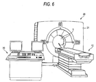
- FIG. 6 is a view showing the external configuration of an X-ray CT apparatus of this embodiment
- FIG. 7 is a block diagram showing the configuration of the X-ray CT apparatus of this embodiment
- FIGS. 8 and 9 are perspective views showing the configuration of a rotating part provided in a gantry of the X-ray CT apparatus of this embodiment
- FIG. 10 is a sectional view showing the configuration of a rotating part 40 of this embodiment.
- the X-ray CT apparatus of this embodiment includes a bed 10 for carrying a subject (not shown), such as a patient, a gantry 20 which has a photographing port 5 for inserting the subject and radiating X-rays, and is covered with a gantry cover 21, and a control device 30 which controls operation of the whole X-ray CT apparatus.
- the bed 10 is made to approach the gantry 20 by the driving unit 61, and the subject carried on the bed 10 is inserted into the photographing port 5 of the gantry 20.
- a rotating part 40 is provided within the gantry 20. As shown in FIG.
- the rotating part includes an X-ray tube unit 41 which generates X-rays, an X-ray detecting unit 42 which is disposed opposite to the X-ray tube unit 41, with a subject therebetween, in order to detect the X-rays radiated from the X-ray tube unit 41 and transmitted through the subject, a signal amplification unit 43 which amplifies the signals detected by the X-ray detecting unit 42, a cooling unit 44 which is provided adjacent to the X-ray tube unit 41 to cool down the X-ray tube unit 41, power units 45 and 46 for supplying tube voltage (tube current) to the X-ray tube unit 41, and a power control unit 47 which controls the power units 45 and 46.
- the rotating part includes the X-ray tube unit 41, the X-ray detecting unit 42, the signal amplification unit 43, the cooling unit 44, the power unit 45 and 46, and the power control unit 47 (Hereinafter, each of these units each may be referred to a rotating part unit).
- the control device 30 includes an input unit 31 for inputting various commands required for acquisition of an X-ray CT image, a display unit 32 which displays information required for acquisition of an X-ray CT image, an acquired X-ray CT image, etc., a storage unit 33 which stores information required for acquisition of an X-ray CT image, an acquired X-ray CT image, etc., and a system control unit 34 which controls operation of each unit of the X-ray CT apparatus.
- the rotating part 40 is rotated by a drive motor 51 under the control of a rotation control unit 50. This rotates the rotating part 40 at high speed around a subject.
- the rotational speed of the rotating part 40 is, for example, more than 1 second/rotation, particularly, more than 0.5 seconds/rotation. That is, in order to obtain an X-ray CT image of a subject, the time that the rotating part 40 is required to make one rotation around a subject becomes 1 second or less, particularly, 0.5 seconds or less.
- X-rays are radiated to the subject from the X-ray tube unit 41 by supplying a predetermined tube voltage (tube current) to the X-ray tube unit 41 from the power units 45 and 46 under the control of the power control unit 47, and the X-rays transmitted through the subject are detected by the X-ray detecting unit 42 while the rotating part 40 goes around the subject.
- the detection signals related to the X-rays detected by the X-ray detecting unit 42 are amplified by the signal amplification unit 43, and are supplied to the system control unit 34.
- the system control unit 34 performs predetermined image reconstruction processing, etc. on the basis of the detection signals, to acquire an X-ray CT image, and makes the acquired X-ray CT image displayed on the display unit 32 and stored the image in the storage unit 33.
- FIG. 8 the bed side of the rotating part 40 will be referred to as "front side,” and the opposite side will be referred to as "back side.” Accordingly, the perspective view shown in FIG. 8 is referred to as a perspective view when viewed from the front side, and the perspective view shown in FIG. 9 is referred to as a perspective view when viewed from the back side. Further, the back side of the rotating part 40 is omitted in FIG. 8.
- the rotating part 40 is fabricated of, for example, aluminum cast, and has on the front side thereof a ring-shaped flat plate part (flat plate) 48 which rotates about a rotational axis N (refer to FIG. 10) around a subject inserted into the photographing port 5.
- An outer peripheral end of the flat plate part 48 is formed with a drum part (cylinder) 49 which is coaxial with the shape of a ring and wider than the width (plate thickness) of the flat plate part 48 in the direction of the rotational axis N.
- the drum part 49 as shown in FIG. 10, is formed from the front side of the flat plate part 48 to the rear side thereof, and a joining portion of the flat plate part 48 and the drum part 49 has a T-shaped cross section.
- a combination of the flat plate part 48 and the drum part 49 may be referred to as a rotary base 52.
- the length of the flat plate part 48 in a rotational radial direction (refer to FIG. 10) perpendicular to the rotational axis N, i.e., the width of a ring shape is such that the X-ray detecting unit 42 is attached. Further, the X-ray tube unit 41, the X-ray detecting unit 42, the signal amplification unit 43, the cooling unit 44, the power units 45 and 46, and the power control unit 47, which are the above-mentioned rotating part units, are attached to the front side of the flat plate part 48 with fixing bolts (not shown).
- the width of a cylinder of the drum part 49 in the direction of the rotational axis N is such that each of the above units attached to the flat plate part 48 does not protrude from the cylinder of the drum part 49 in the direction of the rotational axis N.
- the X-ray tube unit 41 is disposed so as to form a transmission surface of X-rays parallel to the flat plate part 48 in a position away from the flat plate part 48 in the direction of the rotational axis N.
- the center of gravity of the X-ray tube unit 41 is often in the vicinity the X-ray generated position. That is, also in this embodiment, the center of gravity of the X-ray tube unit 41 will be in a position that is away from the flat plate part 48 toward the transmission surface of X-rays in the direction of the rotational axis N.
- a reinforcing member 25 is attached to the rotary base 52 on the back side of the flat plate part 48, and constitutes a double structure together with the rotary base 52.
- the reinforcing member 25 is fabricated of, for example, aluminum cast.
- the reinforcing member has a ring-shaped and L-shaped section as an example like the flat plate part 48. Further, the length of the reinforcing member 25 in the rotational radial direction is almost the same as the length of the flat plate part 48 in the rotational radial direction.
- the reinforcing member 25 is joined to the drum part 49 from the back side using fixing bolts (not shown) at a plurality of attaching parts 101 in the positions in the vicinity of an outer peripheral end of the rotary base 52. Further, the reinforcing member, as shown in FIG. 8, is joined to the flat plate part 48 from the front side using fixing bolts (not shown) at a plurality of attaching parts 102 in the positions in the vicinity of an inner peripheral end of the rotary base 52. Further, a hollow part 26 is defined between the reinforcing member 25 and the flat plate part 48.
- the reinforcing member 25 By attaching the reinforcing member 25 in this way, the geometrical moment of inertia in a direction perpendicular to the rotational axial direction increases, and consequently the strength against bending in the direction of the rotational axis N increases. Further, the hollow part 26 is formed to reduce an increase in weight, and the attaching member is simply attached along the flat plate part 48 to increase the geometrical moment of inertia and consequently further increase the strength.
- this embodiment illustrates an example in which the reinforcing member 25 sandwiches a bearing 91 together with a bearing holding part 24 so that the rotating part 40 is rotatably held by the frame 23 using the bearing 91.
- the rotary base 52 rotates about the rotational axis N, and the X-ray tube unit 41 rotates around a subject inserted into the photographing port 5.
- a centrifugal force acts on the center of gravity of the X-ray tube unit 41 in a direction (outward) away from the rotational axis N, and a component force of the centrifugal force F serves as a bending moment which tends to deform the flat plate part 48 in the direction of the rotational axis N.
- the strength of the rotary base 52 is increased by the reinforcing member 25 as described above, deformation of the rotary base 52 can be suppressed.
- the rotating part 40 rotates, the degree of precision of the position of a transmission surface of X-rays can be ensured.
- the rotating part can be rotated at high speed, and photographing can be made while the rotational speed is changed.
- the rotating part unit as shown in FIG. 8, is attached to the front side of the flat plate part 48 so that maintenance can be performed easily from the front side, the reinforcing member 25 is attached to the back side of the flat plate part 48.
- the workability at the time of maintenance will not be lowered.
- the thickness of the flat plate part 48 is not increased, a problem in fabrication or deterioration of the degree of precision of a shape is not caused, for example, in a case where the rotary base 52 is fabricated of aluminum cast.
- the reinforcing member 25 is formed into a ring shape in this embodiment, the reinforcing member, for example, may be formed into a shape which partially reinforces at least the vicinity of the X-ray tube unit 41, etc. as a double structure to suppress deformation.
- the rotating part unit may be attached to the inner peripheral face (unit attaching face) of the drum part 49 like the X-ray CT apparatus described in JP-A No. 2000-116641 .
- the provision of the reinforcing member 25 can suppress deformation of the rotary base 52.
- the attachment of the rotating part unit to the inner peripheral face of the drum part 49 may be performed using fixing bolts, etc., or otherwise may be performed by providing a guide rail in the inner peripheral face of the drum part 49, and then causing a rotating part unit to slide along the guide rail.
Abstract
Description
- The present invention relates to an X-ray computed tomographic apparatus including a rotating part which rotates in order to acquire an X-ray tomographic image of a subject.
- An X-ray computed tomographic apparatus (hereinafter referred to as "X-ray CT (Computed Tomography) apparatus"), which provides the information on a subject as an image on the basis of the intensity of X-rays transmitted through the subject, plays an important role in many medical acts, including diagnosis of diseases, medical care, surgery planning, etc.
- Such an X-ray CT apparatus has an annular rotary base. This rotary base is supported so as to be rotatable about the axial center thereof, and various devices, such as an X-ray tube, an X-ray detector, and a high-voltage generator, are fixed inside the rotary base.
- Rotation of the rotary base will change the orientation of the X-ray tube and the X-ray detector. In the X-ray CT apparatus, photographing of a subject from various directions is made using a change in the orientation of the above-mentioned X-ray tube and X-ray detector (for example, refer to
JP-A No. 8-52130 - Meanwhile, since the X-ray tube, the X-ray detector, the high-voltage generator, etc. have heavy weight, when the rotary base rotates at high speed, a great centrifugal force may be generated in heavy loads, such as the X-ray tube, the X-ray detector, and the high-voltage generator, which are fixed inside the rotary base, and consequently the rotary base may be deformed.
- Since the angle of the X-rays radiated from the X-ray tube will deviate if the installation angle of the X-ray tube gets wrong due to deformation of the rotary base, it becomes impossible for the X-ray detector to detect the X-rays correctly. Moreover, when deviation occurs in an X-ray path, the position where X-rays are detected will change and deterioration of an image will be caused.
- Hereinafter, another case will be further described as an example with reference to FIG. 11.
- FIG. 11 is a sectional view showing the configuration of a conventional
rotating part 40. As shown in FIG. 11, arotating part 40 which can rotate continuously at high speed (for example, greater than 1 second/rotation) in order to acquire an X-ray tomographic image of a subject is provided in a gantry of a conventional X-ray CT apparatus. This rotatingpart 40 is rotatably held in aframe 23 via abearing 91. AnX-ray tube unit 41, anX-ray detecting unit 42, asignal amplification unit 43, and other units (not shown) are attached to therotating part 40. Hereinafter, each of these units may be called a rotating part unit. Each of these rotating part units is attached to a ring-shaped flat plate part 48 (flat plate) centering on a rotational axis N. - A drum-
shaped drum part 49 is formed in an outer peripheral end of theflat plate part 48. Hereinbelow, a combination of theflat plate part 48 and thedrum part 49 is referred to as arotary base 52. Therotary base 52 is held in theframe 23 via thebearing 91. Thebearing 91 is sandwiched by theflat plate part 48 and thebearing holding part 24. - An X-ray CT apparatus in which each rotating part unit is attached to the inside of the
drum part 49 is disclosed (see, for example,JP-A No. 2000-116641 rotating part 40, the center of gravity of each rotating part unit in the direction of the rotational axis N of therotating part 40 does not often coincide with the position of theflat plate part 48. For example, theX-ray tube unit 41 and theX-ray detecting unit 42 are disposed such that the X-rays radiated from theX-ray tube unit 41 and transmitted through a subject is detected by theX-ray detecting unit 42 disposed opposite to theX-ray tube unit 41, with the subject therebetween. That, theX-ray tube unit 41 is disposed so as to form a transmission surface of X-rays parallel to theflat plate part 48 in a position away from the flat plate part in the direction of the rotational axis N. In this case, the center of gravity of theX-ray tube unit 41 is often in the vicinity of a position where X-rays are generated. Specifically, heavy things, such as a rotor (anode) and protective lead for shielding leakage X-rays are disposed in the vicinity of the X-ray generated position. Accordingly, the center of gravity of theX-ray tube unit 41 will be in a position that is away from theflat plate part 48 in the direction of the rotational axis N. Further, since theX-ray detecting unit 42 is disposed on the side of an X-ray transmission surface of theflat plate part 48, the center of gravity of theX-ray detecting unit 42 will be in a position that is away from theflat plate part 48 in the direction of the rotational axis N, like the center of gravity of theX-ray tube unit 41. Moreover, since other rotating part units are disposed on the same side as theX-ray tube unit 41 andX-ray detecting unit 42 with respect to theflat plate part 48 from the viewpoint of easiness of work at the time of maintenance, the center of gravity often deviates, similar to theX-ray tube unit 41 orX-ray detecting unit 42. - When the rotating
part 40 rotates at high speed, a centrifugal force will act on the center of gravity of each rotating part unit. For example; a centrifugal force F which acts on theX-ray tube unit 41 is shown in FIG. 11 as an example. For example, in a case where the distance from the rotational axis N to the center of gravity of theX-ray tube unit 41 is 600 mm and rotational speed is 0.5 second/rotation, the gravitational acceleration of about 10G is generated. Further, in a case where the distance from the rotational axis N to the center of gravity of theX-ray tube unit 41 is 600 mm and the rotational speed is 0.4 seconds/rotation, the gravitational acceleration of about 15G is generated. - Meanwhile, if the center of gravity of the
X-ray tube unit 41 has deviated from the position of theflat plate part 48 in the direction of the rotational axis N as mentioned above, a component force F1 of the centrifugal force F which acts on each rotating part unit when therotating part 40 rotates at high speed may act on a holding position of therotary base 52 as a bending moment, and theflat plate part 48 may be deformed accordingly. Similarly, the centrifugal force may also act on theX-ray detecting unit 42 or other rotating part units to deform theflat plate part 48. Although there is a difference in deformation volume even in a case where each rotating part unit is attached to the inside of thedrum part 49 as disclosed inJP-A No. 2000-116641 flat plate part 48 similarly. The deformation of theflat plate part 48 based on the centrifugal force F makes it difficult to ensure the degree of precision of the position of the X-ray transmission surface at the time of high-speed rotation. - Thus, there is also a case where the X-ray transmission surface is made wide so that the
X-ray detecting unit 42 can detect X-rays with a high degree of precision. In this case, however, the amount of exposure of a subject will be increased. Further, in a case where the degree of deformation of theflat plate part 48 is great, breakage of therotary base 52, abnormality of a CT image due to shift of CT values, etc. may be caused. - On the other hand, although there is a demand for shortening the time required for photographing a moving object, for example, a heart, etc., that is, a demand for photographing the moving object while being made to rotate at higher speed so that the object can be observed as if it stands still, the above-mentioned deformation will be increased due to the higher-speed rotation.
- Further, there is also a demand for photographing an object while the rotational speed is changed. Since a centrifugal force will change if rotational speed is changed, deformation volume will also change with the change in rotational speed. Therefore, there is a fear that abnormality of a CT image may be further caused due to the change in deformation volume.
- Further, although it is considered that the strength of the
flat plate part 48 is raised by increasing the thickness thereof, therotary base 52 is often fabricated of aluminum cast. In this case, if the thickness of the rotary base is increased partially, a problem occurs in flow or cooling of molten metal of the cast. As a result, there is a fear that, for example, an internal stress may be generated or the degree of precision of a shape may deteriorate. On the other hand, if the whole rotary base including thedrum part 49 is thickened, the weight thereof increases, and thereby a motor to drive the rotary base is also required to be enlarged. As a result, there is a problem that the X-ray CT apparatus may be enlarged. - Further, depending on a method of reinforcing the
rotary base 52, lowering of the workability at the time of maintenance as described above may be caused. - The invention provides an X-ray computed tomographic apparatus that, even if a rotary base rotates at high speed, deterioration of image quality is hardly caused without deviation of the installation angle of an X-ray tube and a detector.
- The invention provides an X-ray computed tomographic apparatus capable of reinforcing a rotary base without enlarging the apparatus.
- The X-ray computed tomographic apparatus of the invention is configured as follows.
- (1) An X-ray computed tomographic apparatus includes a cylindrical rotary base supported so as to be rotatable about a rotational axis, an X-ray tube mounted on the rotary base, an X-ray detector mounted on the rotary base, and a reinforcing ring fixed to the rotary base, and having a greater rigidity than the rotary base.
- (2) In the X-ray computed tomographic apparatus as set forth in (1), the X-ray tube and the X-ray detector are disposed in positions offset toward the same side from a central part of the rotary base in the axial direction thereof, and the reinforcing ring is provided at an end, which is close to the X-ray tube and the X-ray detector, of the ends of the rotary base in the axial direction thereof.
- (3) In the X-ray computed tomographic apparatus as set forth in
claim 1, the reinforcing ring is fixed to an end face of the rotary base. - (4) In the X-ray computed tomographic apparatus as set forth in (1), the reinforcing ring is fixed to an outer peripheral face of the rotary base.
- (5) In the X-ray computed tomographic apparatus as set forth in (1), the reinforcing ring is formed of any one of iron, stainless steel, and titanium.
- (6) An X-ray computed tomographic apparatus includes a cylindrical rotary base supported so as to be rotatable about a rotational axis, an X-ray tube mounted on the rotary base, an X-ray detector mounted on the rotary base, and a reinforcing member fabricated of a material having a greater rigidity than the rotary base, and attached to an end of the rotary base to suppress deflection of the rotary base.
- (7) In an X-ray computed tomographic apparatus having a rotating part which rotates in order to acquire an X-ray tomographic image of a subject, the rotating part includes a rotary base having a ring-shaped flat plate centering on a rotational axis of the rotating part, and a cylinder formed at an outer peripheral end of the flat plate, an X-ray tube which radiates X-rays to the subject on any one surface of the flat plate, and a reinforcing member attached to the rotary base on the other surface of the flat plate, and constituting a double structure along with the rotary base.
- (8) In the X-ray computed tomographic apparatus as set forth in (7), the reinforcing member is joined to the rotary base in the vicinity of inner and outer peripheral ends of the rotary base.
- (9) In the X-ray computed tomographic apparatus as set forth in (7), a hollow part is formed between the reinforcing member and the flat plate.
- (10) In the X-ray computed tomographic apparatus as set forth in (7), the reinforcing member has a ring shape.
- (11) In the X-ray computed tomographic apparatus as set forth in (7), the X-ray tube is attached to an inner peripheral face of the cylinder.
- According to the X-ray computed tomographic apparatus, even if the rotary base rotates at high speed, deviation of the installation angle of an X-ray tube and a detector does not deviate, and deterioration of image quality is hardly caused. Moreover, it is not necessary to enlarge the apparatus.
- The invention can be more fully understood from the following detailed description when taken in conjunction with the accompanying drawings, in which:
- FIG. 1 is a perspective view of an X-ray CT apparatus according to the first embodiment of the invention;
- FIG. 2 is a schematic view of a gantry according to the first embodiment;
- FIG. 3 is a perspective view of a rotary base according to the first embodiment;
- FIG. 4 is a sectional side view of the rotary base according to the first embodiment;
- FIG. 5 is a sectional side view of a rotary base according to a modified example of the first embodiment; FIG. 6 is a view showing the external configuration of an X-ray CT apparatus according to a second embodiment of the invention;
- FIG. 7 is a block diagram showing the configuration of the X-ray CT apparatus according to the second embodiment;
- FIG. 8 is a perspective view showing the configuration of a rotating part provided within a gantry of the X-ray CT apparatus according to the second embodiment;
- FIG. 9 is a perspective view showing the configuration of the rotating part provided within the gantry of the X-ray CT apparatus according to the second embodiment;
- FIG. 10 is a sectional view showing the configuration of the rotating part provided within the gantry of the X-ray CT apparatus according to the second embodiment; and
- FIG. 11 is a sectional view showing the configuration of the rotating part provided within the gantry of the X-ray CT apparatus according to the second embodiment.
- First, a first embodiment of the invention will be described referring to FIGS. 1 to 5.
- FIG. 1 is a perspective view of an X-ray CT apparatus according to the first embodiment of the invention.
- As shown in FIG. 1, the X-ray CT apparatus includes a
gantry 20 which radiates X-rays to a subject and acquires image signals in a plurality of sections of the subject on the basis of the X-rays transmitted through the subject, acontrol device 30 which controls operation of thegantry 20 and creates diagnostic images in the plurality of sections of the subject on the basis of the image signals acquired by thegantry 20, and abed 10 which positions the subject in a photographing position of thegantry 20. - An important element in this embodiment is a
rotary base 11 provided within thegantry 20. Accordingly, the description of a part which is not so important in this embodiment, for example, a housing part is omitted in the following description. Further, in the description of this embodiment, the "front" indicates the near side in FIG. 1, and the "rear" indicates the rear side in FIG. 1. - FIG. 2 is a schematic view of the
gantry 20 according to this embodiment. - As shown in FIG. 2, the
gantry 20 includes a photographingport 5 into which a subject is put during photographing, and acylindrical rotary base 11 is disposed inside thegantry 20 so as to surround the photographingport 5 and to be coaxial with the photographingport 5. Therotary base 11 is rotated at high speed about the axial center of therotary base 11 by a drive mechanism disposed within thegantry 20. - FIG. 3 is a perspective view of the
rotary base 11 according to the first embodiment, and FIG. 4 is a sectional side view of therotary base 11 according to the first embodiment. - As shown in FIGS. 3 and 4, the
rotary base 11 has a cylindrical shape as mentioned above, and has therein fixed anX-ray tube unit 12 which radiates X-rays to a subject which is put into the photographingport 5, anX-ray detecting unit 13 which detects the X-rays transmitted through the subject, and apower unit 14 which generates a high voltage to be applied to theX-ray tube unit 12. TheseX-ray tube unit 12,X-ray detecting unit 13, andpower unit 14 are so-called heavy loads whose weight is very heavy. Aluminum, etc. is used as a material of therotary base 11. - The
X-ray tube unit 12 is fixed to a position which is slightly offset forward from an axial central part of therotary base 11 in an inner peripheral face of therotary base 11. Accordingly, the center of gravity of theX-ray tube unit 12 is biased forward of therotary base 11. Bolts are used for fixation of therotary base 11 and theX-ray tube unit 12. - The
X-ray detecting unit 13 is fixed to a front face of an attachingmember 11b provided in the inner peripheral face of therotary base 11. The attachingmember 11b is disposed in substantially the central part of therotary base 11 in the axial direction thereof. Accordingly, both the center of gravity of theX-ray detecting unit 13 fixed to the front face of the attachingmember 11b and the center of gravity of theX-ray tube unit 12 are biased forward of therotary base 11. Bolts are used for fixation of the attachingmember 11b and theX-ray detecting unit 13, and fixation of the attachingmember 11b and thepower unit 14. - A reinforcing
ring 15 is fixed to a front end face of therotary base 11 so that it may be coaxial with therotary base 11. The reinforcingring 15 is composed of a plurality of, for example, four circular-arc members 15a. Accordingly, the manufacture is markedly simplified compared with a case in which the reinforcingring 15 is composed of one member. However, the reinforcingring 15 according the invention may be a one ring-shaped member, not limited thereto. - A fixing
ring 16 is disposed at a front end face of the reinforcingring 15. The fixingring 16 is composed of a plurality of, for example, four circular-arc fixing members 16a. Each fixingmember 16a is disposed so as to cover a joint of the circular-arc members 15a constituting the reinforcingring 15, thereby joining theadjacent fixing members 16a with bolts. Bolts (not shown) are used for fixation of the reinforcingring 15 to therotary base 11. The bolts may be common to the bolts which are used to join the above-mentioned reinforcingring 15. As a material of the reinforcingring 15, iron, stainless steel, or titanium that is a material whose rigidity is higher than aluminum is used. In addition, another fixing ring (not shown) may be disposed at the front end face of the fixingring 16. - Next, the operation and effects of the X-ray CT apparatus having the above configuration will be described.
- When the
rotary base 11 rotates at high speed, a great centrifugal force will be generated in heavy loads, such as theX-ray tube unit 12,X-ray detecting unit 13, andpower unit 14, which are disposed inside the rotary base, and a force which tries to spread will act on a front end of therotary base 11. - However, the reinforcing
ring 15 is fixed to the front end face of therotary base 11 in this embodiment. Moreover, as the material of the reinforcingring 15, iron, stainless steel, or titanium whose rigidity is higher than the material of therotary base 11 is used. - Accordingly, even if a great force which tries to spread acts on the front end of the
rotary base 1, therotary base 11 will not be deformed by virtue of the rigidity of the reinforcingring 15. As a result, even when the installation angle of theX-ray tube unit 12 orX-ray detecting unit 13, which are disposed inside therotary base 11, is kept constant and therotary base 11 rotates at high speed, a stable and clear diagnostic image is created. - Moreover, since only the reinforcing
ring 15 is attached, it can be simply introduced into a conventional X-ray computed tomographic apparatus having no reinforcingring 15. That is, even in an X-ray computed tomographic apparatus on condition of rotating therotary base 11 at low speed, it is possible to cope with high-speed rotation of therotary base 11 only by attaching the reinforcingring 15. - Next, referring to FIG. 5, a reinforcing
ring 17 according to a modified example of this embodiment will be described. - FIG. 5 is a sectional side view of the
rotary base 11 according to the modified example of this embodiment. - As shown in FIG. 5, the reinforcing
ring 17 in this embodiment is fixed to an inner peripheral face of a front end of therotary base 11. That is, the reinforcingring 17 is fitted on the outside of therotary base 11. - The reinforcing
ring 17 is composed of a plurality of, for example, four circular-arc members 17a. Accordingly, the manufacture is markedly simplified compared with a case in which the reinforcingring 17 is composed of one member. However, the reinforcingring 17 according the invention may be a one ring-shaped member, not limited thereto. - A fixing
ring 18 is disposed at a front end face of the reinforcingring 17. The fixingring 18 is composed of a plurality of, for example, four circular-arc fixing members 18a. Each fixingmember 18a is disposed so as to cover a joint of the circular-arc members 17a constituting the reinforcingring 17, and the adjacent reinforcingrings 18a are joined together with bolts. Bolts (not shown) are used for fixation of the reinforcingring 17 to therotary base 11. In addition, although this embodiment has been described about the case in which the fixingring 18 is disposed at the front end face of the reinforcingring 17, the fixing ring may be fixed to, for example, the outer peripheral face of the reinforcingring 17. As a material of the reinforcingring 17, iron, stainless steel, or titanium that is a material whose rigidity is higher than aluminum is used. In addition, another fixing ring (not shown) may be disposed at the front end face of the fixingring 18. - In this way, when the reinforcing
ring 17 is fixed to the outer peripheral face of therotary base 11, attachment of the reinforcingring 17 is simplified. Further, only small intensity is required for bolts used for fixation of therotary base 11 and the reinforcingring 17. - In addition, although this embodiment has been described about the case in which iron, stainless steel, and titanium are used as the material of the reinforcing
ring rotary base 11. Accordingly, the material of the reinforcingring rotary base 11. - Moreover, in this embodiment, the reinforcing
ring rotary base 11. However, if the centers of gravity of theX-ray tube unit 12,X-ray detecting unit 13, andpower unit 14 are biased toward the rear of therotary base 11, the reinforcingring rotary base 11. Of course, the reinforcingrings rotary base 11 irrespective of the center of gravity of theX-ray tube unit 12,X-ray detecting unit 13, andpower unit 14. - Furthermore, in this embodiment, bolts are used for fixation of the
rotary base 11 and theX-ray tube unit 12, fixation of therotary base 11 and theX-ray detecting unit 13, fixation of therotary base 11 and thepower unit 14, and fixation of therotary base 11 and the reinforcingring rotary base 11. - Next, referring to FIGS. 6 to 10, a second embodiment of the invention will be described.
- FIG. 6 is a view showing the external configuration of an X-ray CT apparatus of this embodiment, FIG. 7 is a block diagram showing the configuration of the X-ray CT apparatus of this embodiment, FIGS. 8 and 9 are perspective views showing the configuration of a rotating part provided in a gantry of the X-ray CT apparatus of this embodiment, and FIG. 10 is a sectional view showing the configuration of a
rotating part 40 of this embodiment. - In FIG. 6, the X-ray CT apparatus of this embodiment includes a
bed 10 for carrying a subject (not shown), such as a patient, agantry 20 which has a photographingport 5 for inserting the subject and radiating X-rays, and is covered with agantry cover 21, and acontrol device 30 which controls operation of the whole X-ray CT apparatus. - In a case where an X-ray CT image of a subject is acquired, the
bed 10 is made to approach thegantry 20 by the drivingunit 61, and the subject carried on thebed 10 is inserted into the photographingport 5 of thegantry 20. Arotating part 40 is provided within thegantry 20. As shown in FIG. 8, the rotating part includes anX-ray tube unit 41 which generates X-rays, anX-ray detecting unit 42 which is disposed opposite to theX-ray tube unit 41, with a subject therebetween, in order to detect the X-rays radiated from theX-ray tube unit 41 and transmitted through the subject, asignal amplification unit 43 which amplifies the signals detected by theX-ray detecting unit 42, a coolingunit 44 which is provided adjacent to theX-ray tube unit 41 to cool down theX-ray tube unit 41,power units X-ray tube unit 41, and apower control unit 47 which controls thepower units X-ray tube unit 41, theX-ray detecting unit 42, thesignal amplification unit 43, the coolingunit 44, thepower unit - As shown in FIG. 7, the
control device 30 includes aninput unit 31 for inputting various commands required for acquisition of an X-ray CT image, adisplay unit 32 which displays information required for acquisition of an X-ray CT image, an acquired X-ray CT image, etc., astorage unit 33 which stores information required for acquisition of an X-ray CT image, an acquired X-ray CT image, etc., and asystem control unit 34 which controls operation of each unit of the X-ray CT apparatus. - Further, the
rotating part 40 is rotated by adrive motor 51 under the control of arotation control unit 50. This rotates therotating part 40 at high speed around a subject. In addition, the rotational speed of therotating part 40 is, for example, more than 1 second/rotation, particularly, more than 0.5 seconds/rotation. That is, in order to obtain an X-ray CT image of a subject, the time that therotating part 40 is required to make one rotation around a subject becomes 1 second or less, particularly, 0.5 seconds or less. - In a case where an X-ray CT image of a subject is acquired, X-rays are radiated to the subject from the
X-ray tube unit 41 by supplying a predetermined tube voltage (tube current) to theX-ray tube unit 41 from thepower units power control unit 47, and the X-rays transmitted through the subject are detected by theX-ray detecting unit 42 while therotating part 40 goes around the subject. The detection signals related to the X-rays detected by theX-ray detecting unit 42 are amplified by thesignal amplification unit 43, and are supplied to thesystem control unit 34. Thesystem control unit 34 performs predetermined image reconstruction processing, etc. on the basis of the detection signals, to acquire an X-ray CT image, and makes the acquired X-ray CT image displayed on thedisplay unit 32 and stored the image in thestorage unit 33. - Hereinafter, the configuration of the rotating part of this embodiment will be described in detail with reference to FIGS. 8 to 10. In addition, in description of this embodiment, the bed side of the
rotating part 40 will be referred to as "front side," and the opposite side will be referred to as "back side." Accordingly, the perspective view shown in FIG. 8 is referred to as a perspective view when viewed from the front side, and the perspective view shown in FIG. 9 is referred to as a perspective view when viewed from the back side. Further, the back side of therotating part 40 is omitted in FIG. 8. - As shown in FIG. 8, the
rotating part 40 is fabricated of, for example, aluminum cast, and has on the front side thereof a ring-shaped flat plate part (flat plate) 48 which rotates about a rotational axis N (refer to FIG. 10) around a subject inserted into the photographingport 5. An outer peripheral end of theflat plate part 48 is formed with a drum part (cylinder) 49 which is coaxial with the shape of a ring and wider than the width (plate thickness) of theflat plate part 48 in the direction of the rotational axis N. Thedrum part 49, as shown in FIG. 10, is formed from the front side of theflat plate part 48 to the rear side thereof, and a joining portion of theflat plate part 48 and thedrum part 49 has a T-shaped cross section. Hereinbelow, a combination of theflat plate part 48 and thedrum part 49 may be referred to as arotary base 52. - The length of the
flat plate part 48 in a rotational radial direction (refer to FIG. 10) perpendicular to the rotational axis N, i.e., the width of a ring shape is such that theX-ray detecting unit 42 is attached. Further, theX-ray tube unit 41, theX-ray detecting unit 42, thesignal amplification unit 43, the coolingunit 44, thepower units power control unit 47, which are the above-mentioned rotating part units, are attached to the front side of theflat plate part 48 with fixing bolts (not shown). Further, the width of a cylinder of thedrum part 49 in the direction of the rotational axis N is such that each of the above units attached to theflat plate part 48 does not protrude from the cylinder of thedrum part 49 in the direction of the rotational axis N. Further, theX-ray tube unit 41 is disposed so as to form a transmission surface of X-rays parallel to theflat plate part 48 in a position away from theflat plate part 48 in the direction of the rotational axis N. Further, as discussed in "Description of Related Art," since a rotor (positive pole) and a heavy thing, such as protective lead for shielding leakage X-rays, are disposed in the vicinity of a position where X-rays are generated, the center of gravity of theX-ray tube unit 41 is often in the vicinity the X-ray generated position. That is, also in this embodiment, the center of gravity of theX-ray tube unit 41 will be in a position that is away from theflat plate part 48 toward the transmission surface of X-rays in the direction of the rotational axis N. - Further, as shown in FIGS. 9 and 10, a reinforcing
member 25 is attached to therotary base 52 on the back side of theflat plate part 48, and constitutes a double structure together with therotary base 52. The reinforcingmember 25 is fabricated of, for example, aluminum cast. In this embodiment, the reinforcing member has a ring-shaped and L-shaped section as an example like theflat plate part 48. Further, the length of the reinforcingmember 25 in the rotational radial direction is almost the same as the length of theflat plate part 48 in the rotational radial direction. Further, the reinforcingmember 25 is joined to thedrum part 49 from the back side using fixing bolts (not shown) at a plurality of attachingparts 101 in the positions in the vicinity of an outer peripheral end of therotary base 52. Further, the reinforcing member, as shown in FIG. 8, is joined to theflat plate part 48 from the front side using fixing bolts (not shown) at a plurality of attachingparts 102 in the positions in the vicinity of an inner peripheral end of therotary base 52. Further, ahollow part 26 is defined between the reinforcingmember 25 and theflat plate part 48. By attaching the reinforcingmember 25 in this way, the geometrical moment of inertia in a direction perpendicular to the rotational axial direction increases, and consequently the strength against bending in the direction of the rotational axis N increases. Further, thehollow part 26 is formed to reduce an increase in weight, and the attaching member is simply attached along theflat plate part 48 to increase the geometrical moment of inertia and consequently further increase the strength. - Further, this embodiment illustrates an example in which the reinforcing
member 25 sandwiches abearing 91 together with abearing holding part 24 so that therotating part 40 is rotatably held by theframe 23 using thebearing 91. - In such a configuration, the
rotary base 52 rotates about the rotational axis N, and theX-ray tube unit 41 rotates around a subject inserted into the photographingport 5. In this case, as described in "BACKGRAND OF THE INVENTION" a centrifugal force acts on the center of gravity of theX-ray tube unit 41 in a direction (outward) away from the rotational axis N, and a component force of the centrifugal force F serves as a bending moment which tends to deform theflat plate part 48 in the direction of the rotational axis N. However, since the strength of therotary base 52 is increased by the reinforcingmember 25 as described above, deformation of therotary base 52 can be suppressed. - Accordingly, even if the
rotating part 40 rotates, the degree of precision of the position of a transmission surface of X-rays can be ensured. As a result, the rotating part can be rotated at high speed, and photographing can be made while the rotational speed is changed. Further, although the rotating part unit, as shown in FIG. 8, is attached to the front side of theflat plate part 48 so that maintenance can be performed easily from the front side, the reinforcingmember 25 is attached to the back side of theflat plate part 48. Thus the workability at the time of maintenance will not be lowered. Further, since the thickness of theflat plate part 48 is not increased, a problem in fabrication or deterioration of the degree of precision of a shape is not caused, for example, in a case where therotary base 52 is fabricated of aluminum cast. - Further, although the reinforcing
member 25 is formed into a ring shape in this embodiment, the reinforcing member, for example, may be formed into a shape which partially reinforces at least the vicinity of theX-ray tube unit 41, etc. as a double structure to suppress deformation. - Further, although the case in which the rotating part unit is attached to the front side of the
flat plate part 48 is described as an example, the rotating part unit may be attached to the inner peripheral face (unit attaching face) of thedrum part 49 like the X-ray CT apparatus described inJP-A No. 2000-116641 drum part 49, the provision of the reinforcingmember 25 can suppress deformation of therotary base 52. - Further, the attachment of the rotating part unit to the inner peripheral face of the
drum part 49, similar to the X-ray CT apparatus described inJP-A No. 2000-116641 drum part 49, and then causing a rotating part unit to slide along the guide rail. - The invention is not limited to the above embodiments themselves, but it can be embodied in practice by modifying constituent elements without departing the scope of the invention. Further, various inventions can be made by combinations of a plurality of suitable constituent elements disclosed in the above embodiments. For example, some constituent elements may be eliminated from all the components shown in the above embodiments.
- It is explicitly stated that all features disclosed in the description and/or the claims are intended to be disclosed separately and independently from each other for the purpose of original disclosure as well as for the purpose of restricting the claimed invention independent of the composition of the features in the embodiments and/or the claims. It is explicitly stated that all value ranges or indications of groups of entities disclose every possible intermediate value or intermediate entity for the purpose of original disclosure as well as for the purpose of restricting the claimed invention, in particular as limits of value ranges.
Claims (11)
- An X-ray computed tomographic apparatus characterized by comprising:a cylindrical rotary base (11) supported so as to be rotatable about a rotational axis;an X-ray tube (12) mounted on the rotary base;an X-ray detector (13) mounted on the rotary base; anda reinforcing ring (15) fixed to the rotary base, and having a greater rigidity than the rotary base.
- The X-ray computed tomographic apparatus according to claim 1,
characterized in that the X-ray tube and the X-ray detector are disposed in positions offset toward the same side from a central part of the rotary base in the axial direction thereof, and
the reinforcing ring is provided at an end, which is close to the X-ray tube and the X-ray detector, of the ends of the rotary base in the axial direction thereof. - The X-ray computed tomographic apparatus according to claim 1,
characterized in that the reinforcing ring is fixed to an end face of the rotary base. - The X-ray computed tomographic apparatus according to claim 1,
characterized in that the reinforcing ring is fixed to an outer peripheral face of the rotary base. - The X-ray computed tomographic apparatus according to claim 1,
characterized in that the reinforcing ring is formed of any one of iron, stainless steel, and titanium. - An X-ray computed tomographic apparatus characterized by comprising:a cylindrical rotary base (11) supported so as to be rotatable about a rotational axis;an X-ray tube (12) mounted on the rotary base;an X-ray detector (13) mounted on the rotary base; anda reinforcing member (15) fabricated of a material having a greater rigidity than the rotary base, and attached to an end of the rotary base to suppress deflection of the rotary base.
- An X-ray computed tomographic apparatus having a rotating part which rotates in order to acquire an X-ray tomographic image of a subject, the rotating part characterized by comprising:a rotary base (11) including a ring-shaped flat plate centering on a rotational axis of the rotating part, and a cylinder formed at an outer peripheral end of the flat plate;an X-ray tube (12) which radiates X-rays to the subject on any one surface of the flat plate; anda reinforcing member (15) attached to the rotary base on the other surface of the flat plate, and constituting a double structure along with the rotary base.
- The X-ray computed tomographic apparatus according to claim 7,
characterized in that the reinforcing member is joined to the rotary base in the vicinity of inner and outer peripheral ends of the rotary base. - The X-ray computed tomographic apparatus according to claim 7,
characterized in that a hollow part is formed between the reinforcing member and the flat plate. - The X-ray computed tomographic apparatus according to claim 7, characterized in that the reinforcing member has a ring shape.
- The X-ray computed tomographic apparatus according to claim 7,
characterized in that the X-ray tube is attached to an inner peripheral face of the cylinder.
Applications Claiming Priority (2)
| Application Number | Priority Date | Filing Date | Title |
|---|---|---|---|
| JP2005261009A JP4761898B2 (en) | 2005-09-08 | 2005-09-08 | X-ray computed tomography system |
| JP2005324386A JP2007130119A (en) | 2005-11-09 | 2005-11-09 | X-ray ct apparatus |
Publications (3)
| Publication Number | Publication Date |
|---|---|
| EP1762177A2 true EP1762177A2 (en) | 2007-03-14 |
| EP1762177A3 EP1762177A3 (en) | 2008-01-30 |
| EP1762177B1 EP1762177B1 (en) | 2014-11-05 |
Family
ID=37649299
Family Applications (1)
| Application Number | Title | Priority Date | Filing Date |
|---|---|---|---|
| EP06018573.3A Active EP1762177B1 (en) | 2005-09-08 | 2006-09-05 | X-ray computed tomographic apparatus |
Country Status (2)
| Country | Link |
|---|---|
| US (1) | US7447294B2 (en) |
| EP (1) | EP1762177B1 (en) |
Cited By (7)
| Publication number | Priority date | Publication date | Assignee | Title |
|---|---|---|---|---|
| WO2009063354A1 (en) | 2007-11-16 | 2009-05-22 | Koninklijke Philips Electronics N.V. | High speed rotating gantry |
| CN110234275A (en) * | 2016-11-15 | 2019-09-13 | 反射医疗公司 | For emitting the system of guiding high-energy photon transmission |
| US11627920B2 (en) | 2008-03-14 | 2023-04-18 | Reflexion Medical, Inc. | Method and apparatus for emission guided radiation therapy |
| US11675097B2 (en) | 2017-07-11 | 2023-06-13 | Reflexion Medical, Inc. | Methods for PET detector afterglow management |
| US11794036B2 (en) | 2016-11-15 | 2023-10-24 | Reflexion Medical, Inc. | Radiation therapy patient platform |
| US11878185B2 (en) | 2015-06-10 | 2024-01-23 | Reflexion Medical, Inc. | High bandwidth binary multi-leaf collimator design |
| US11904184B2 (en) | 2017-03-30 | 2024-02-20 | Reflexion Medical, Inc. | Radiation therapy systems and methods with tumor tracking |
Families Citing this family (12)
| Publication number | Priority date | Publication date | Assignee | Title |
|---|---|---|---|---|
| DE102008036016B4 (en) * | 2008-08-01 | 2012-01-05 | Siemens Aktiengesellschaft | Rotor, gantry and computer tomography device with a rotor on which components of a receiving device are mounted |
| DE102008036019B4 (en) * | 2008-08-01 | 2010-11-11 | Siemens Aktiengesellschaft | Computed tomography device and rotor for a gantry of a computed tomography device |
| US20120032084A1 (en) * | 2009-04-15 | 2012-02-09 | Koninklijke Philips Electronics N. V. | Drive with curved linear induction motor |
| US8781061B2 (en) * | 2009-04-16 | 2014-07-15 | Hitachi Medical Corporation | X-ray CT rotary apparatus |
| US9044152B2 (en) * | 2012-04-05 | 2015-06-02 | Analogic Corporation | Rotatable drum assembly for radiology imaging modalities |
| US8829446B2 (en) | 2012-04-05 | 2014-09-09 | Analogic Corporation | Tile for detector array of imaging modality having selectively removable/replaceable tile sub-assemblies |
| EP2838433B1 (en) * | 2012-04-16 | 2017-10-11 | Neurologica Corp. | Imaging system with rigidly mounted fiducial markers |
| US9254108B2 (en) * | 2014-03-18 | 2016-02-09 | General Electric Company | Gantry with bore safety mechanism |
| CN104198506B (en) * | 2014-08-27 | 2017-11-07 | 清华大学 | Low-angle is from pendulum-type large-sized multiple layer helical CT device and inspection method |
| CN107981880B (en) * | 2016-10-26 | 2021-03-16 | 北京东软医疗设备有限公司 | CT machine and rotator thereof |
| US10575796B2 (en) * | 2017-05-30 | 2020-03-03 | General Electric Company | Computed tomography gantry |
| CN111419259B (en) * | 2020-04-01 | 2023-05-02 | 上海大骋医疗科技有限公司 | Mechanism suitable for installation and adjustment of X-ray tube of CT equipment |
Citations (2)
| Publication number | Priority date | Publication date | Assignee | Title |
|---|---|---|---|---|
| JPH0852130A (en) | 1994-06-07 | 1996-02-27 | Toshiba Corp | X-ray ct apparatus |
| JP2000116641A (en) | 1998-10-16 | 2000-04-25 | Toshiba Corp | X-ray ct instrument |
Family Cites Families (11)
| Publication number | Priority date | Publication date | Assignee | Title |
|---|---|---|---|---|
| US5093850A (en) * | 1976-04-19 | 1992-03-03 | General Electric Company | Tomographic scanning apparatus |
| GB1594274A (en) * | 1976-09-13 | 1981-07-30 | Siemens Ag | Tomographic scanning apparatus |
| US4217499A (en) * | 1976-09-13 | 1980-08-12 | General Electric Company | Tomographic scanning apparatus with ionization detector means |
| US5031198A (en) * | 1989-11-17 | 1991-07-09 | Picker International, Inc. | Composite detector mounting ring for CT scanners |
| JP3256579B2 (en) * | 1992-09-18 | 2002-02-12 | 株式会社島津製作所 | Rotating cathode X-ray tube device |
| US5703921A (en) * | 1995-05-30 | 1997-12-30 | Kabushiki Kaisha Toshiba | X-ray computed tomography apparatus |
| US5761269A (en) | 1995-08-29 | 1998-06-02 | Kabushiki Kaisha Toshiba | X-ray computerized tomography system having cooling features |
| JPH0956710A (en) | 1995-08-29 | 1997-03-04 | Toshiba Corp | X-ray computer tomography apparatus |
| GB9520564D0 (en) * | 1995-10-07 | 1995-12-13 | Philips Electronics Nv | Apparatus for treating a patient |
| JP3633713B2 (en) * | 1996-04-23 | 2005-03-30 | 松下電器産業株式会社 | Distance measuring method and distance sensor |
| DE69937067D1 (en) * | 1998-11-30 | 2007-10-18 | Invision Technologies Inc | IMPROPER INSPECTION SYSTEM |
-
2006
- 2006-09-05 EP EP06018573.3A patent/EP1762177B1/en active Active
- 2006-09-07 US US11/470,902 patent/US7447294B2/en not_active Expired - Fee Related
Patent Citations (2)
| Publication number | Priority date | Publication date | Assignee | Title |
|---|---|---|---|---|
| JPH0852130A (en) | 1994-06-07 | 1996-02-27 | Toshiba Corp | X-ray ct apparatus |
| JP2000116641A (en) | 1998-10-16 | 2000-04-25 | Toshiba Corp | X-ray ct instrument |
Cited By (10)
| Publication number | Priority date | Publication date | Assignee | Title |
|---|---|---|---|---|
| WO2009063354A1 (en) | 2007-11-16 | 2009-05-22 | Koninklijke Philips Electronics N.V. | High speed rotating gantry |
| CN101854864B (en) * | 2007-11-16 | 2013-03-13 | 皇家飞利浦电子股份有限公司 | High speed rotating gantry |
| US8681930B2 (en) | 2007-11-16 | 2014-03-25 | Koninklijke Philips N.V. | High speed rotating gantry |
| US11627920B2 (en) | 2008-03-14 | 2023-04-18 | Reflexion Medical, Inc. | Method and apparatus for emission guided radiation therapy |
| US11878185B2 (en) | 2015-06-10 | 2024-01-23 | Reflexion Medical, Inc. | High bandwidth binary multi-leaf collimator design |
| CN110234275A (en) * | 2016-11-15 | 2019-09-13 | 反射医疗公司 | For emitting the system of guiding high-energy photon transmission |
| CN110234275B (en) * | 2016-11-15 | 2023-08-22 | 反射医疗公司 | System for emission guided high energy photon transport |
| US11794036B2 (en) | 2016-11-15 | 2023-10-24 | Reflexion Medical, Inc. | Radiation therapy patient platform |
| US11904184B2 (en) | 2017-03-30 | 2024-02-20 | Reflexion Medical, Inc. | Radiation therapy systems and methods with tumor tracking |
| US11675097B2 (en) | 2017-07-11 | 2023-06-13 | Reflexion Medical, Inc. | Methods for PET detector afterglow management |
Also Published As
| Publication number | Publication date |
|---|---|
| US20070053479A1 (en) | 2007-03-08 |
| US7447294B2 (en) | 2008-11-04 |
| EP1762177B1 (en) | 2014-11-05 |
| EP1762177A3 (en) | 2008-01-30 |
Similar Documents
| Publication | Publication Date | Title |
|---|---|---|
| EP1762177B1 (en) | X-ray computed tomographic apparatus | |
| JP5677940B2 (en) | X-ray CT system | |
| US6810103B1 (en) | Gantry for combined tomography scanner | |
| US7020233B1 (en) | Dual gantry bearing for combined tomography scanner | |
| US20080025459A1 (en) | X-ray hybrid diagnosis system | |
| US9014341B2 (en) | CT collimator and CT system including the CT collimator | |
| US7073940B2 (en) | Apparatus for mechanical transmission | |
| JPH10328173A (en) | X-ray diagnostic system | |
| EP2211720B1 (en) | High speed rotating gantry | |
| JP2010035984A (en) | X-ray imaging apparatus | |
| JP5342589B2 (en) | X-ray CT system | |
| JPH0888093A (en) | X-ray tube assembly | |
| JP2007037873A (en) | X-ray ct equipment | |
| US7623619B2 (en) | X-ray CT apparatus | |
| KR20150073858A (en) | Rotating frame for the gantry of a computed tompgraphic machine, gantry and computed tompgraphic machine with such a rotating frame | |
| JP4325792B2 (en) | C-arm X-ray device with mechanically adjustable brake | |
| JP5041591B2 (en) | X-ray imaging apparatus and adjusting method of rotating surface thereof | |
| US20210145383A1 (en) | Methods and systems for a medical imaging system with c-arm | |
| JP4761898B2 (en) | X-ray computed tomography system | |
| US20160058398A1 (en) | Rotor for a gantry of a computed tomograpy apparatus | |
| JP2008029846A6 (en) | X-ray imaging apparatus and adjusting method of rotating surface thereof | |
| JP5072223B2 (en) | X-ray CT system | |
| JP2007130119A (en) | X-ray ct apparatus | |
| EP2994050B1 (en) | Imaging system rotating component alignment with iso-center | |
| EP2983590B1 (en) | Computerized tomography (ct) imaging system with improved x-ray tube mount |
Legal Events
| Date | Code | Title | Description |
|---|---|---|---|
| PUAI | Public reference made under article 153(3) epc to a published international application that has entered the european phase |
Free format text: ORIGINAL CODE: 0009012 |
|
| 17P | Request for examination filed |
Effective date: 20060905 |
|
| AK | Designated contracting states |
Kind code of ref document: A2 Designated state(s): AT BE BG CH CY CZ DE DK EE ES FI FR GB GR HU IE IS IT LI LT LU LV MC NL PL PT RO SE SI SK TR |
|
| AX | Request for extension of the european patent |
Extension state: AL BA HR MK YU |
|
| PUAL | Search report despatched |
Free format text: ORIGINAL CODE: 0009013 |
|
| AK | Designated contracting states |
Kind code of ref document: A3 Designated state(s): AT BE BG CH CY CZ DE DK EE ES FI FR GB GR HU IE IS IT LI LT LU LV MC NL PL PT RO SE SI SK TR |
|
| AX | Request for extension of the european patent |
Extension state: AL BA HR MK YU |
|
| 17Q | First examination report despatched |
Effective date: 20080411 |
|
| AKX | Designation fees paid |
Designated state(s): DE NL |
|
| GRAJ | Information related to disapproval of communication of intention to grant by the applicant or resumption of examination proceedings by the epo deleted |
Free format text: ORIGINAL CODE: EPIDOSDIGR1 |
|
| GRAP | Despatch of communication of intention to grant a patent |
Free format text: ORIGINAL CODE: EPIDOSNIGR1 |
|
| RIC1 | Information provided on ipc code assigned before grant |
Ipc: A61B 6/00 20060101ALN20140227BHEP Ipc: A61B 6/03 20060101AFI20140227BHEP |
|
| INTG | Intention to grant announced |
Effective date: 20140404 |
|
| INTC | Intention to grant announced (deleted) | ||
| GRAJ | Information related to disapproval of communication of intention to grant by the applicant or resumption of examination proceedings by the epo deleted |
Free format text: ORIGINAL CODE: EPIDOSDIGR1 |
|
| GRAP | Despatch of communication of intention to grant a patent |
Free format text: ORIGINAL CODE: EPIDOSNIGR1 |
|
| INTG | Intention to grant announced |
Effective date: 20140618 |
|
| RIC1 | Information provided on ipc code assigned before grant |
Ipc: A61B 6/03 20060101AFI20140610BHEP Ipc: A61B 6/00 20060101ALN20140610BHEP |
|
| GRAS | Grant fee paid |
Free format text: ORIGINAL CODE: EPIDOSNIGR3 |
|
| GRAA | (expected) grant |
Free format text: ORIGINAL CODE: 0009210 |
|
| AK | Designated contracting states |
Kind code of ref document: B1 Designated state(s): DE NL |
|
| RIN1 | Information on inventor provided before grant (corrected) |
Inventor name: HARADA, TOMOKAZU Inventor name: NAKANO, MAKOTO Inventor name: SADOTOMO, TETSUYA Inventor name: GOTANDA, KATSUMI Inventor name: SHINDO, YASUTAKA |
|
| REG | Reference to a national code |
Ref country code: DE Ref legal event code: R081 Ref document number: 602006043553 Country of ref document: DE Owner name: TOSHIBA MEDICAL SYSTEMS CORPORATION, OTAWARA-S, JP Free format text: FORMER OWNERS: KABUSHIKI KAISHA TOSHIBA, TOKIO/TOKYO, JP; TOSHIBA MEDICAL SYSTEMS CORPORATION, OTAWARA-SHI, TOCHIGI-KEN, JP |
|
| REG | Reference to a national code |
Ref country code: DE Ref legal event code: R096 Ref document number: 602006043553 Country of ref document: DE Effective date: 20141218 |
|
| RAP2 | Party data changed (patent owner data changed or rights of a patent transferred) |
Owner name: KABUSHIKI KAISHA TOSHIBA Owner name: TOSHIBA MEDICAL SYSTEMS CORPORATION |
|
| REG | Reference to a national code |
Ref country code: NL Ref legal event code: T3 |
|
| REG | Reference to a national code |
Ref country code: DE Ref legal event code: R097 Ref document number: 602006043553 Country of ref document: DE |
|
| PLBE | No opposition filed within time limit |
Free format text: ORIGINAL CODE: 0009261 |
|
| STAA | Information on the status of an ep patent application or granted ep patent |
Free format text: STATUS: NO OPPOSITION FILED WITHIN TIME LIMIT |
|
| 26N | No opposition filed |
Effective date: 20150806 |
|
| REG | Reference to a national code |
Ref country code: NL Ref legal event code: PD Owner name: TOSHIBA MEDICAL SYSTEMS CORPORATION; JP Free format text: DETAILS ASSIGNMENT: VERANDERING VAN EIGENAAR(S), OVERDRACHT; FORMER OWNER NAME: TOSHIBA MEDICAL SYSTEMS CORPORATION Effective date: 20160627 |
|
| REG | Reference to a national code |
Ref country code: DE Ref legal event code: R081 Ref document number: 602006043553 Country of ref document: DE Owner name: TOSHIBA MEDICAL SYSTEMS CORPORATION, OTAWARA-S, JP Free format text: FORMER OWNERS: KABUSHIKI KAISHA TOSHIBA, TOKYO, JP; TOSHIBA MEDICAL SYSTEMS CORP., OTAWARA-SHI, TOCHIGI, JP Ref country code: DE Ref legal event code: R082 Ref document number: 602006043553 Country of ref document: DE Representative=s name: KRAMER BARSKE SCHMIDTCHEN PATENTANWAELTE PARTG, DE |
|
| PGFP | Annual fee paid to national office [announced via postgrant information from national office to epo] |
Ref country code: NL Payment date: 20230719 Year of fee payment: 18 |
|
| PGFP | Annual fee paid to national office [announced via postgrant information from national office to epo] |
Ref country code: DE Payment date: 20230712 Year of fee payment: 18 |