EP1775402A2 - Connecting and disconnecting device for sliding wing and upright - Google Patents
Connecting and disconnecting device for sliding wing and upright Download PDFInfo
- Publication number
- EP1775402A2 EP1775402A2 EP06352017A EP06352017A EP1775402A2 EP 1775402 A2 EP1775402 A2 EP 1775402A2 EP 06352017 A EP06352017 A EP 06352017A EP 06352017 A EP06352017 A EP 06352017A EP 1775402 A2 EP1775402 A2 EP 1775402A2
- Authority
- EP
- European Patent Office
- Prior art keywords
- connecting rod
- translation
- finger
- female element
- ramp
- Prior art date
- Legal status (The legal status is an assumption and is not a legal conclusion. Google has not performed a legal analysis and makes no representation as to the accuracy of the status listed.)
- Withdrawn
Links
Images


Classifications
-
- E—FIXED CONSTRUCTIONS
- E05—LOCKS; KEYS; WINDOW OR DOOR FITTINGS; SAFES
- E05B—LOCKS; ACCESSORIES THEREFOR; HANDCUFFS
- E05B65/00—Locks or fastenings for special use
- E05B65/08—Locks or fastenings for special use for sliding wings
- E05B65/087—Locks or fastenings for special use for sliding wings the bolts sliding parallel to the wings
-
- E—FIXED CONSTRUCTIONS
- E05—LOCKS; KEYS; WINDOW OR DOOR FITTINGS; SAFES
- E05B—LOCKS; ACCESSORIES THEREFOR; HANDCUFFS
- E05B47/00—Operating or controlling locks or other fastening devices by electric or magnetic means
- E05B47/0001—Operating or controlling locks or other fastening devices by electric or magnetic means with electric actuators; Constructional features thereof
- E05B47/0002—Operating or controlling locks or other fastening devices by electric or magnetic means with electric actuators; Constructional features thereof with electromagnets
-
- E—FIXED CONSTRUCTIONS
- E05—LOCKS; KEYS; WINDOW OR DOOR FITTINGS; SAFES
- E05B—LOCKS; ACCESSORIES THEREFOR; HANDCUFFS
- E05B47/00—Operating or controlling locks or other fastening devices by electric or magnetic means
- E05B47/02—Movement of the bolt by electromagnetic means; Adaptation of locks, latches, or parts thereof, for movement of the bolt by electromagnetic means
- E05B47/026—Movement of the bolt by electromagnetic means; Adaptation of locks, latches, or parts thereof, for movement of the bolt by electromagnetic means the bolt moving rectilinearly
-
- E—FIXED CONSTRUCTIONS
- E05—LOCKS; KEYS; WINDOW OR DOOR FITTINGS; SAFES
- E05B—LOCKS; ACCESSORIES THEREFOR; HANDCUFFS
- E05B47/00—Operating or controlling locks or other fastening devices by electric or magnetic means
- E05B47/0001—Operating or controlling locks or other fastening devices by electric or magnetic means with electric actuators; Constructional features thereof
- E05B47/0002—Operating or controlling locks or other fastening devices by electric or magnetic means with electric actuators; Constructional features thereof with electromagnets
- E05B47/0003—Operating or controlling locks or other fastening devices by electric or magnetic means with electric actuators; Constructional features thereof with electromagnets having a movable core
- E05B47/0004—Operating or controlling locks or other fastening devices by electric or magnetic means with electric actuators; Constructional features thereof with electromagnets having a movable core said core being linearly movable
Definitions
- the present invention relates to hooking and unhooking devices between a slider and an upright, which find a particularly advantageous application in electrical control systems for closing and opening sliding doors, windows, French windows or the like. , especially in homes.
- the object of the present invention is to provide a hooking and unhooking device between a slider and a frame, or between two sliders able to move relative to one another, which finds a particularly advantageous application in electric lock systems while having a relatively simple structure, and which is easy to install.
- said male element is formed on said connecting rod and the female element on said upright.
- the first end of the connecting rod comprises one of the following means: a flat, a notch, an oblong orifice, said finger being mounted in cooperation with one of these means.
- said finger is constituted by a roller.
- the means for mounting said link rod in displacement with respect to said slide in the second direction Tr comprise a groove, said connecting rod being mounted in translation in said groove.
- the amount is a sliding frame amount.
- the object of the invention comprises "at least one" element having a given function
- the embodiment described may comprise several of these elements.
- the embodiment of the object according to the invention as illustrated has several elements of identical function and if, in the description, it is not specified that the object according to this invention must obligatorily comprise a number particular of these elements, the object of the invention may be defined as comprising "at least one" of these elements.
- the present invention relates to a hooking device and stall between a slider 6 and a post 12 or the like, the slider being able to move in translation in a first direction Dd relative to a frame 20 or the like to get closer or away from the amount 12.
- the translation of the sliding is obtained in a conventional manner by one or more trolleys 50, known in themselves.
- the hooking and unhitching between the slider 6 and the upright 12 are obtained by the cooperation of two respectively male 1 and female 10 elements.
- the male element 1 is able to penetrate into the female element 10 and to leave it when the sliding member 6 moves towards or away from the upright 12 in the first direction of translation Dd, and to hook onto the female element and unhook when, when it is in the female element, it moves in translation in a direction or in the other following a second direction Tr making with the first direction Dd a non-zero angle.
- the angle between them the second direction Tr and the first direction Dd is substantially equal to ninety degrees.
- the male element 1 is constituted by a bolt and the female element is constituted by a striker 10, as illustrated in Figures 1 to 3.
- the device according to the invention comprises a connecting rod 2, such as a cremone bolt or the like, means 5 for mounting the connecting rod in displacement relative to the sliding member in the second direction Tr, first means for mounting a first 1, 10 two elements on the connecting rod 2, and second means for mounting the second 10, 1 of the two elements on the upright 12.
- a connecting rod 2 such as a cremone bolt or the like
- means 5 for mounting the connecting rod in displacement relative to the sliding member in the second direction Tr
- first means for mounting a first 1, 10 two elements on the connecting rod 2 and second means for mounting the second 10, 1 of the two elements on the upright 12.
- the device further comprises means 30 for transforming the displacements in translation of the slider 6 in the first direction Dd, of opposite directions between two first and second positions P C1 , P C2 with respect to the chassis 20, in two displacements in translation of the connecting rod 2 along the second direction Tr, of opposite directions between two first and second positions P t1 , P t2 , the first position P t1 of the rod 2 corresponding to the first position P C1 of the slider 6 in which the two elements 1 10, are spaced from each other, and the second position P t2 of the rod 2 corresponding to the second position P C2 of the slider 6 in which the male element 1 has penetrated into the female element 10 without being hooked, and means 40 for controlling the passage of the connecting rod 2 from its second position P t2 to a third position P t3 and vice versa, when the slider is in its second position P C2 , so that the male element 1 clings to the element female 10 or unhooks.
- the male element 1 like a bolt
- the female element 10 like a keeper
- the hook 11 of the bolt 1 being turned down with reference to Figure 1.
- the present invention applies both to a fixed amount 12 relative to the frame 20 to a fixed amount of a second sliding which is adapted to translate in the same plane as the first sliding 6 relative to the chassis 20 following the first direction Dd.
- the amount 12 of the second slider will be considered fixed, assuming that the second slider has taken its final closing position, so that the bolt of one of the two sliders and the latch of the other are able to cooperate as explained in the present description.
- the means 30 for transforming the two displacements into translation of the slider 6 along the first direction Dd in two translation displacements of the connecting rod 2 following the second direction Tr, movements more amply defined above are constituted by a finger 9 secured to a first end 7 of the connecting rod 2, a ramp 3 with a slope 31 determined, means for mounting the ramp 3 in cooperation with the frame 20 so that, when the slider 6 passes from its first position P C1 to its second position P C2 (and reciprocally), the finger 9 travels the slope 31 and passes from a first level to a second level, the slope 31 being determined so that the difference in level between these two first and second levels equal to the amplitude of the displacement in translation of the connecting rod 2 defined along the second direction Tr between its first and second positions P t1 , P t2 , the ramp 3 being furthermore positioned relative to the frame 20 so that when the sliding member 6 reaches its second position P C2 , the finger 9 leaves the top 32 of the ramp
- the means 40 for controlling the passage of the connecting rod 2, when the slider 6 is in its second position P C2 , its second position P t2 to a third position P t3 and vice versa, so that the male element 1 hooks or detaches from the female element 10, comprise, firstly to move the connecting rod from its second position P t2 to its third position P t3 , elastic means 18 to tend to bring back the connecting rod in its first position P t1 , and secondly to move the connecting rod from its third position P t3 to its second position P t2 , means 14 for applying a traction force on the finger 9 of to bring it back to the level of the summit 32 of the ramp 3.
- the means 14 for applying a traction force on the finger 9 so as to return it to the top 32 of the ramp 3 are constituted by a tab 19, or the like, positioned relative to the ramp 3 to be able to receive the finger 9 when it leaves the top 32 of the ramp 3, an electromagnet 42 integral with the frame 20, and a core 41 integral with the tab 19 and mounted in cooperation with the electromagnet 42 so that it is able to be translated next the second direction Tr by driving the tab 19 as described below.
- the finger 9 can be mounted in cooperation with the first end 7 of the connecting rod 2 in various ways, in particular by one of the following means: a flat, the finger then being offset from this plate, a notch 8 as illustrated in FIG. 1, the finger then being at the top on an edge of the notch, or an oblong orifice, the finger then being mounted at the top of this oblong orifice, as illustrated in FIG.
- the finger 9 is constituted, for example, by a roller mounted in rotation.
- the means 5 for mounting the connecting rod 2, for example a cremone or the like, in displacement relative to the sliding member 6 in the second direction Tr consist of a groove 5 made for example on the profile constituting the slice of the slider 6, the connecting rod 2 then being mounted in translation in this groove.
- the slider 6 and the amount 12 are then hooked to one another, which prevents any opening of the slider relative to the amount.
- the user wants to open the slider he controls the electromagnet 14, for example by means of an electric button, which raises the core 41 and thus the tab 19 which brings the roller 9 at the top 32 of the ramp 3.
- the bolt 1 has returned to its position 100 and the user can act to move the slide from its position P C2 to its position P C1 corresponding to the opening of the sliding, the roller 9 rolling again on the ramp 3 to return to its original position at the bottom of the ramp.
- the essential advantage of the device according to the invention in addition to the simplicity of its structure lies in the fact that its operation can be fully automated, allowing the user to exert no effort, or to move the sliding 6, nor to hang on the amount, or to pick it up.
- the spring 18 connects the connecting rod 2 to a low point of the slide 6.
- the connecting rod 2 to tend to hold the connecting rod 2 in its first position P t1 , it works in traction .
- it could connect the connecting rod 2 for example to a high point of the sliding and, in this case, it would work in thrust.
- FIGS. 1 and 2 show a first preferred embodiment of the device according to the invention, in which the bolt 1 is mounted on the slider 6 and the striker 2 on the upright 12, the hook 11 of the bolt being turned towards the bottom of the sliding when it moves, as normally, in a vertical position on carriages 50 with respect to slide rails 51.
- FIG. 3 represents another possible embodiment of the invention, in which the striker 10 is mounted on the connecting rod 2 and therefore able to translate on the slide 6 in the second direction Tr, and the bolt 1 is mounted on the upright 12.
- the slope 31 of the ramp 3 is the opposite of that illustrated in FIGS. and 2
- the spring 18 (schematically shown) acts in thrust to tend to raise the rod 2
- the lug 19 in cooperation with the electromagnet 42 via the core 41 is mounted to push the roller 9 down when the electromagnet is controlled to allow the stall between the striker 10 and the bolt 1.
- the rest position of the electromagnet is that in which the tab 19 is in the upper position for example by means of a traction spring between it and the chassis 20.
Abstract
Description
La présente invention concerne les dispositifs d'accrochage et de décrochage entre un coulissant et un montant, qui trouvent une application particulièrement avantageuse dans les systèmes à commande électrique pour la fermeture et l'ouverture de coulissants de portes, fenêtres, portes-fenêtres ou analogues, notamment dans les habitations.The present invention relates to hooking and unhooking devices between a slider and an upright, which find a particularly advantageous application in electrical control systems for closing and opening sliding doors, windows, French windows or the like. , especially in homes.
Il est connu aujourd'hui des systèmes à commande électrique pour la fermeture et l'ouverture d'une porte traditionnelle de type battante intérieure ou extérieure, que les techniciens dénomment sous le terme générique de "serrures électriques".It is known today electric control systems for the closing and opening of a traditional indoor or outdoor swing type door, which technicians call the generic term "electric locks".
Cependant, les systèmes de serrures électriques actuellement connus s'appliquent exclusivement aux portes à ouverture battante.However, currently known electric lock systems apply exclusively to swing opening doors.
Aussi, la présente invention a-t-elle pour but de réaliser un dispositif d'accrochage et de décrochage entre un coulissant et un dormant, ou entre deux coulissants aptes à se déplacer l'un par rapport à l'autre, qui trouve une application particulièrement avantageuse dans les systèmes de serrure à commande électrique tout en présentant une structure relativement simple, et qui soit facile à installer.Also, the object of the present invention is to provide a hooking and unhooking device between a slider and a frame, or between two sliders able to move relative to one another, which finds a particularly advantageous application in electric lock systems while having a relatively simple structure, and which is easy to install.
Plus précisément, la présente invention a pour objet un dispositif d'accrochage et de décrochage entre un coulissant et un montant, le coulissant étant apte à se déplacer en translation suivant une première direction par rapport à un châssis pour se rapprocher ou s'éloigner du montant, l'accrochage et le décrochage entre le coulissant et le montant étant obtenus par la coopération de deux éléments, l'un des deux éléments étant un élément mâle et l'autre un élément femelle, l'élément mâle étant apte à pénétrer dans l'élément femelle et à en sortir lorsque le coulissant se rapproche ou s'éloigne du montant suivant la première direction de translation, et à s'accrocher à l'élément femelle et se décrocher lorsque, quand il est dans l'élément femelle, il se déplace en translation suivant une seconde direction faisant avec la première direction un angle non nul, dans un sens ou dans l'autre,
caractérisé par le fait qu'il comporte :
- une tige de liaison,
- des moyens pour monter ladite tige de liaison en déplacement par rapport au dit coulissant suivant la seconde direction,
- des premiers moyens pour monter un premier des deux élément sur ladite tige de liaison,
- des seconds moyens pour monter le second des deux éléments sur ledit montant,
- des moyens pour transformer les déplacements en translation du coulissant suivant la première direction, de sens opposés entre deux première et seconde positions par rapport au châssis, en deux déplacements en translation de la tige de liaison suivant la seconde direction, de sens opposés entre deux première et deuxième positions, la première position de la tige correspondant à la première position du coulissant dans laquelle les deux éléments sont éloignés l'un de l'autre, et la deuxième position de la tige correspondant à la seconde position du coulissant dans laquelle l'élément mâle a pénétré dans l'élément femelle sans être accroché au dit élément femelle, et
- des moyens pour commander le passage de la tige de liaison de sa deuxième position à une troisième position et réciproquement, quand le coulissant est dans sa seconde position, de façon que l'élément mâle s'accroche ou se décroche de l'élément femelle.
characterized by the fact that it comprises:
- a connecting rod,
- means for mounting said link rod moving relative to said slide in the second direction,
- first means for mounting a first of the two elements on said connecting rod,
- second means for mounting the second of the two elements on said upright,
- means for converting displacements in translation of the slider in the first direction, of opposite directions between two first and second positions relative to the chassis, in two displacements in translation of the connecting rod in the second direction, of opposite directions between first two and second positions, the first position of the rod corresponding to the first position of the slide in which the two elements are spaced from each other, and the second position of the rod corresponding to the second position of the slide in which the male element has penetrated into the female element without being hooked to said female element, and
- means for controlling the passage of the connecting rod from its second position to a third position and vice versa, when the slider is in its second position, so that the male member is hooked or unhooked from the female member.
Selon une caractéristique avantageuse, les moyens pour transformer les deux déplacements en translation du coulissant suivant la première direction Dd, de sens opposés entre deux première et seconde positions par rapport au châssis, en deux déplacements en translation de la tige de liaison suivant la seconde direction Tr, de sens opposés entre deux première et deuxième positions, la première position de la tige correspondant à la première position du coulissant dans laquelle les deux éléments sont éloignés l'un de l'autre, et la seconde position de la tige correspondant à la deuxième position du coulissant dans laquelle l'élément mâle a pénétré dans l'élément femelle sans être accroché au dit élément femelle, sont constitués par :
- un doigt solidaire d'une première extrémité de la tige de liaison,
- une rampe avec une pente déterminée,
- des moyens pour monter la rampe en coopération avec le châssis de façon que, lorsque le coulissant passe de sa première position Pc1 à sa seconde position Pc2 et réciproquement, le doigt parcourt la pente et passe d'un premier niveau à un second niveau, la pente étant déterminée de façon que la différence de niveau entre ces deux premier et second niveaux soit égale à l'amplitude du déplacement en translation défini suivant la seconde direction Tr, de la tige de liaison entre ses première et deuxième positions Pt1, Pt2, la rampe étant en outre positionnée par rapport au châssis de façon que, lorsque le coulissant arrive à sa seconde position Pc2, le doigt quitte le sommet de la rampe.
- a finger secured to a first end of the connecting rod,
- a ramp with a determined slope,
- means for mounting the ramp in cooperation with the chassis so that when the sliding passes from its first position P c1 to its second position P c2 and vice versa, the finger travels the slope and goes from a first level to a second level , the slope being determined so that the difference in level between these two first and second levels is equal to the amplitude of the displacement in translation defined along the second direction Tr, of the connecting rod between its first and second positions P t1 , P t2 , the ramp being further positioned relative to the frame so that when the slide reaches its second position P c2 , the finger leaves the top of the ramp.
Selon une caractéristique avantageuse, les moyens pour commander le passage de la tige de liaison, quand le coulissant est dans sa seconde position, de sa deuxième position à une troisième position et réciproquement, de façon que l'élément mâle s'accroche ou se décroche de l'élément femelle, comportent :
- pour faire passer la tige de liaison de sa deuxième position Pt2 à sa troisième position Pt3, des moyens élastiques pour tendre à ramener ladite tige de liaison dans sa première position Pt1, et
- pour faire passer la tige de liaison de sa troisième position Pt3 à sa deuxième position Pt2, des moyens pour appliquer une force de traction sur le doigt, de façon à le ramener au niveau du sommet de la rampe.
- to move the connecting rod from its second position P t2 to its third position P t3 , elastic means for tending to return said connecting rod in its first position P t1 , and
- to move the connecting rod from its third position P t3 to its second position P t2 , means for applying a traction force on the finger, so as to bring it to the level of the top of the ramp.
Selon une caractéristique avantageuse, les moyens pour appliquer une force de traction sur le doigt, de façon à le ramener au sommet de la rampe, sont constitués par :
- une patte montée en coopération avec la rampe de façon à recevoir ledit doigt,
- un électroaimant, et
- un noyau monté solidaire de la patte et en coopération avec ledit électroaimant.
- a tab mounted in cooperation with the ramp so as to receive said finger,
- an electromagnet, and
- a core mounted integral with the tab and in cooperation with said electromagnet.
Selon une caractéristique avantageuse, ledit élément mâle est réalisé sur ladite tige de liaison et l'élément femelle sur ledit montant.According to an advantageous characteristic, said male element is formed on said connecting rod and the female element on said upright.
Selon une caractéristique avantageuse, la première extrémité de la tige de liaison comporte l'un des moyens suivant : un plat, une encoche, un orifice oblong, ledit doigt étant monté en coopération avec l'un de ces moyens.According to an advantageous characteristic, the first end of the connecting rod comprises one of the following means: a flat, a notch, an oblong orifice, said finger being mounted in cooperation with one of these means.
Selon une caractéristique avantageuse, ledit doigt est constitué par un galet.According to an advantageous characteristic, said finger is constituted by a roller.
Selon une caractéristique avantageuse, les moyens pour monter ladite tige de liaison en déplacement par rapport au dit coulissant suivant la seconde direction Tr, comprennent une rainure, ladite tige de liaison étant montée en translation dans ladite rainure.According to an advantageous characteristic, the means for mounting said link rod in displacement with respect to said slide in the second direction Tr, comprise a groove, said connecting rod being mounted in translation in said groove.
Selon une caractéristique avantageuse, le montant est un montant de châssis coulissant.According to an advantageous characteristic, the amount is a sliding frame amount.
D'autres caractéristiques et avantages de l'invention apparaîtront au cours de la description suivante donnée en regard des dessins annexés à titre illustratif mais nullement limitatif, dans lesquels :
- La figure 1 représente le schéma fonctionnel d'un premier mode de réalisation du dispositif d'accrochage et de décrochage selon l'invention entre un coulissant et un montant,
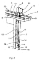
- La figure 2 représente une vue en perspective cavalière d'une partie d'un mode de réalisation industriel du dispositif d'accrochage et de décrochage selon l'invention en accord avec le schéma selon la figure 1, et
- La figure 3 représente un schéma d'une partie d'un autre mode de réalisation du dispositif d'accrochage et de décrochage selon l'invention entre un coulissant et un montant.
- FIG. 1 represents the block diagram of a first embodiment of the hooking and unhooking device according to the invention between a slider and an amount,
- FIG. 2 represents a perspective view in a perspective view of part of an industrial embodiment of the hooking and unhooking device according to the invention in accordance with the diagram according to FIG. 1, and
- Figure 3 shows a diagram of a portion of another embodiment of the attachment device and stall according to the invention between a sliding and an amount.
Il est tout d'abord précisé que, sur les figures, les mêmes références désignent les mêmes éléments, quelle que soit la figure sur laquelle elles apparaissent et quelle que soit la forme de représentation de ces éléments. De même, si des éléments ne sont pas spécifiquement référencés sur l'une des figures, leurs références peuvent être aisément retrouvées en se reportant à une autre figure.It is first of all specified that, in the figures, the same references designate the same elements, whatever the figure on which they appear and whatever the form of representation of these elements. Similarly, if elements are not specifically referenced in one of the figures, their references can be easily found by referring to another figure.
Il est aussi précisé que les figures représentent essentiellement deux modes de réalisation de l'objet selon l'invention, mais qu'il peut exister d'autres modes de réalisation qui répondent à la définition de cette invention.It is also stated that the figures essentially represent two embodiments of the object according to the invention, but that there may be other embodiments that meet the definition of this invention.
Il est en outre précisé que, lorsque, selon la définition de l'invention, l'objet de l'invention comporte "au moins un" élément ayant une fonction donnée, le mode de réalisation décrit peut comporter plusieurs de ces éléments. Réciproquement, si le mode de réalisation de l'objet selon l'invention tel qu'illustré comporte plusieurs éléments de fonction identique et si, dans la description, il n'est pas spécifié que l'objet selon cette invention doit obligatoirement comporter un nombre particulier de ces éléments, l'objet de l'invention pourra être défini comme comportant "au moins un" de ces éléments.It is furthermore specified that, when, according to the definition of the invention, the object of the invention comprises "at least one" element having a given function, the embodiment described may comprise several of these elements. Conversely, if the embodiment of the object according to the invention as illustrated has several elements of identical function and if, in the description, it is not specified that the object according to this invention must obligatorily comprise a number particular of these elements, the object of the invention may be defined as comprising "at least one" of these elements.
Il est enfin précisé que lorsque, dans la présente description, une expression définit à elle seule, sans mention particulière spécifique la concernant, un ensemble de caractéristiques structurelles, ces caractéristiques peuvent être prises, pour la définition de l'objet de la protection demandée, quand cela est techniquement possible, soit séparément, soit en combinaison totale et/ou partielle.Lastly, it is specified that when, in the present description, an expression defines, by itself, without a specific particular mention concerning it, a set of structural characteristics, these characteristics may be taken, for the definition of the object of the protection requested, when technically possible, either separately, or in full and / or partial combination.
La présente invention a pour objet un dispositif d'accrochage et de décrochage entre un coulissant 6 et un montant 12 ou analogue, le coulissant étant apte à se déplacer en translation suivant une première direction Dd par rapport à un châssis 20 ou analogue pour se rapprocher ou s'éloigner du montant 12. La translation du coulissant est obtenue de façon classique par un ou plusieurs chariots 50, connus en eux-mêmes.The present invention relates to a hooking device and stall between a
L'accrochage et le décrochage entre le coulissant 6 et le montant 12 sont obtenus par la coopération de deux éléments respectivement mâle 1 et femelle 10. L'élément mâle 1 est apte à pénétrer dans l'élément femelle 10 et à en sortir lorsque le coulissant 6 se rapproche ou s'éloigne du montant 12 suivant la première direction de translation Dd, et à s'accrocher à l'élément femelle et se décrocher lorsque, quand il est dans l'élément femelle, il se déplace en translation dans un sens ou dans l'autre suivant une seconde direction Tr faisant avec la première direction Dd un angle non nul.The hooking and unhitching between the
De façon préférentielle, l'angle que font entre elles la seconde direction Tr et la première direction Dd est sensiblement égal à quatre-vingt dix degrés. Dans une réalisation habituelle, l'élément mâle 1 est constitué par un pêne et l'élément femelle est constitué par une gâche 10, comme illustré sur les figures 1 à 3.Preferably, the angle between them the second direction Tr and the first direction Dd is substantially equal to ninety degrees. In a usual embodiment, the
Le dispositif selon l'invention comporte une tige de liaison 2, comme une crémone ou analogue, des moyens 5 pour monter cette tige de liaison en déplacement par rapport au coulissant suivant la seconde direction Tr, des premiers moyens pour monter un premier 1, 10 des deux éléments sur la tige de liaison 2, et des seconds moyens pour monter le second 10, 1 des deux éléments sur le montant 12.The device according to the invention comprises a connecting
Ces deux derniers moyens de montage sont bien connus en eux-mêmes et ne seront pas plus amplement décrits ici, dans le seul souci de simplifier la présente description.These last two mounting means are well known in themselves and will not be further described here, for the sole purpose of simplifying the present description.
Le dispositif comporte en outre des moyens 30 pour transformer les déplacements en translation du coulissant 6 suivant la première direction Dd, de sens opposés entre deux première et seconde positions PC1, PC2 par rapport au châssis 20, en deux déplacements en translation de la tige de liaison 2 suivant la seconde direction Tr, de sens opposés entre deux première et deuxième positions Pt1, Pt2, la première position Pt1 de la tige 2 correspondant à la première position PC1 du coulissant 6 dans laquelle les deux éléments 1, 10 sont éloignés l'un de l'autre, et la deuxième position Pt2 de la tige 2 correspondant à la seconde position PC2 du coulissant 6 dans laquelle l'élément mâle 1 a pénétré dans l'élément femelle 10 sans lui être accroché, et des moyens 40 pour commander le passage de la tige de liaison 2 de sa deuxième position Pt2 à une troisième position Pt3 et réciproquement, quand le coulissant est dans sa seconde position PC2, de façon que l'élément mâle 1 s'accroche à l'élément femelle 10 ou se décroche.The device further comprises means 30 for transforming the displacements in translation of the
Dans les réalisations illustrées sur les figures 1 et 2, l'élément mâle 1, comme un pêne, est monté solidaire de la tige de liaison 2, tandis que l'élément femelle 10, comme une gâche, est monté sur le montant 12, le crochet 11 du pêne 1 étant tourné vers le bas par référence à la figure 1. Mais il est bien évident qu'une configuration symétrique par rapport à la direction Dd est possible, à savoir avec le crochet 11 du pêne tourné vers le haut de la figure 1 et une position de la gâche adaptée à celle du pêne, c'est-à-dire symétrique de celle illustrée par rapport à la direction Dd.In the embodiments illustrated in FIGS. 1 and 2, the
Il est également souligné que la présente invention s'applique aussi à un montage inverse, c'est-à-dire avec la gâche 10 montée sur la tige de liaison 2 et le pêne 1 sur le montant 12. Ce mode de réalisation inverse sera succinctement décrit ci-après en regard de la figure 3.It is also emphasized that the present invention also applies to a reverse assembly, that is to say with the
De même, la présente invention s'applique aussi bien à un montant 12 fixe par rapport au châssis 20 qu'à un montant solidaire d'un second coulissant qui est apte à se translater dans le même plan que le premier coulissant 6 par rapport au châssis 20 suivant la première direction Dd. Pour cette dernière application, le montant 12 du second coulissant sera considéré comme fixe, en supposant que ce second coulissant aura pris sa position définitive de fermeture, de façon que le pêne de l'un des deux coulissants et la gâche de l'autre soient aptes à coopérer comme explicité dans la présente description.Similarly, the present invention applies both to a fixed
Comme illustré sur les figures 1 et 2, et même la figure 3, de façon très avantageuse, les moyens 30 pour transformer les deux déplacements en translation du coulissant 6 suivant la première direction Dd en deux déplacements en translation de la tige de liaison 2 suivant la seconde direction Tr, déplacements plus amplement définis ci-dessus, sont constitués par un doigt 9 solidaire d'une première extrémité 7 de la tige de liaison 2, une rampe 3 avec une pente 31 déterminée, des moyens pour monter la rampe 3 en coopération avec le châssis 20 de façon que, lorsque le coulissant 6 passe de sa première position PC1 à sa seconde position PC2 (et réciproquement), le doigt 9 parcourt la pente 31 et passe d'un premier niveau à un second niveau, la pente 31 étant déterminée de façon que la différence de niveau entre ces deux premier et second niveaux soit égale à l'amplitude du déplacement en translation de la tige de liaison 2 défini suivant la seconde direction Tr entre ses première et deuxième positions Pt1, Pt2, la rampe 3 étant en outre positionnée par rapport au châssis 20 de façon que, lorsque le coulissant 6 arrive à sa seconde position PC2, le doigt 9 quitte le sommet 32 de la rampe 3.As illustrated in FIGS. 1 and 2, and even FIG. 3, in a very advantageous manner, the
De façon préférentielle, les moyens 40 pour commander le passage de la tige de liaison 2, quand le coulissant 6 est dans sa seconde position PC2, de sa deuxième position Pt2 à une troisième position Pt3 et réciproquement, de façon que l'élément mâle 1 s'accroche ou se décroche de l'élément femelle 10, comportent, d'une part pour faire passer la tige de liaison de sa deuxième position Pt2 à sa troisième position Pt3, des moyens élastiques 18 pour tendre à ramener la tige de liaison dans sa première position Pt1, et d'autre part pour faire passer la tige de liaison de sa troisième position Pt3 à sa deuxième position Pt2, des moyens 14 pour appliquer une force de traction sur le doigt 9 de façon à le ramener au niveau du sommet 32 de la rampe 3.Preferably, the
Avantageusement, les moyens 14 pour appliquer une force de traction sur le doigt 9 de façon à le ramener au sommet 32 de la rampe 3, sont constitués par une patte 19, ou analogue, positionnée par rapport à la rampe 3 pour être apte à recevoir le doigt 9 quand il quitte le sommet 32 de la rampe 3, un électroaimant 42 solidaire du châssis 20, et un noyau 41 solidaire de la patte 19 et monté en coopération avec l'électroaimant 42 pour qu'il soit apte à être translaté suivant la seconde direction Tr en entraînant la patte 19 comme décrit ci-après.Advantageously, the
Le doigt 9 peut être monté en coopération avec la première extrémité 7 de la tige de liaison 2 de différentes façons, notamment par l'un des moyens suivants: un plat, le doigt étant alors en déport de ce plat, une encoche 8 comme illustré sur la figure 1, le doigt étant alors au sommet sur un bord de l'encoche, ou un orifice oblong, le doigt étant alors monté sommet de cet orifice oblong, comme illustré sur la figure 2.The finger 9 can be mounted in cooperation with the
En outre, pour faciliter le glissement du doigt sur la pente 31 de la rampe 3, il est avantageux que ce doigt 9 soit constitué, par exemple, par un galet monté en rotation.In addition, to facilitate the sliding of the finger on the
Enfin, dans une réalisation avantageuse, les moyens 5 pour monter la tige de liaison 2, par exemple une crémone ou analogue, en déplacement par rapport au coulissant 6 suivant la seconde direction Tr, sont constitués par une rainure 5 réalisée par exemple sur le profilé constituant la tranche du coulissant 6, la tige de liaison 2 étant alors montée en translation dans cette rainure.Finally, in an advantageous embodiment, the
Le mode de réalisation du dispositif décrit ci-dessus en regard des figures 1 et 2 fonctionne de la façon suivante :The embodiment of the device described above with reference to FIGS. 1 and 2 operates as follows:
On suppose tout d'abord que le coulissant 6 est en position ouverte, c'est-à-dire éloigné du montant 12, la tige de liaison 2 étant alors en position Pt1 sous l'action des moyens élastiques 18, c'est-à-dire un ressort de traction dans le mode de réalisation illustré sur ces figures 1 et 2. L'électroaimant 42 est en position de repos, sans action sur le noyau 41, et la patte 19 est en position basse par exemple sous l'action de la pesanteur ou d'un ressort.It is assumed firstly that the
Pour obtenir la fermeture du coulissant 6, il est translaté suivant la direction Dd vers le montant 12. Quand il arrive à sa première position PC1, le galet 9 rencontre la rampe 3. Quand le coulissant passe de sa première position PC1 à sa seconde position PC2, le galet gravit la pente 31 de la rampe 3 pour faire passer la tige 2, à l'encontre du ressort de traction 18, de sa première position Pt1 à sa deuxième position Pt2, cette dernière position étant celle dans laquelle le galet 9 atteint et dépasse le sommet 32 de la rampe 3. Dans cette position Pt2 de la tige 2, le pêne 1 a pénétré dans la gâche 10, comme illustré en traits interrompus en 100 sur la figure 1.To obtain the closure of the
Quand le galet 9 dépasse le sommet 32 de la rampe 3, il tombe vers la patte 19 sous l'action exercée par le ressort de traction 18 agissant sur la tige 2. Dans ce mouvement, le pêne 1 vient dans la position illustrée en traits pointillés en 101 sur la figure 1, dans laquelle son crochet 11 est positionné derrière la paroi de retenue 102 de la gâche 10.When the roller 9 exceeds the top 32 of the
Le coulissant 6 et le montant 12 sont alors accrochés l'un à l'autre, ce qui empêche toute ouverture du coulissant par rapport au montant.The
Si l'utilisateur veut procéder à l'ouverture du coulissant, il commande l'électroaimant 14, par exemple au moyen d'un bouton électrique, qui remonte le noyau 41 et donc la patte 19 qui ramène le galet 9 au niveau du sommet 32 de la rampe 3. Le pêne 1 a repris sa position 100 et l'utilisateur peut agir pour déplacer le coulissant, de sa position PC2 vers sa position PC1 correspondant à l'ouverture du coulissant, le galet 9 roulant à nouveau sur la rampe 3 jusqu'à reprendre sa position origine en bas de la rampe.If the user wants to open the slider, he controls the
L'avantage essentiel du dispositif selon l'invention, outre la simplicité de sa structure, réside dans le fait que son fonctionnement peut être entièrement automatisé, permettant à l'utilisateur de n'exercer aucun effort, ni pour déplacer le coulissant 6, ni pour l'accrocher au montant, ni pour le décrocher.The essential advantage of the device according to the invention, in addition to the simplicity of its structure lies in the fact that its operation can be fully automated, allowing the user to exert no effort, or to move the sliding 6, nor to hang on the amount, or to pick it up.
Dans ce qui vient d'être décrit, le ressort 18 relie la tige de liaison 2 à un point bas du coulissant 6. De ce fait, pour tendre à maintenir la tige de liaison 2 dans sa première position Pt1, il travaille en traction. Mais, dans une réalisation équivalente, il pourrait relier la tige de liaison 2 par exemple à un point haut du coulissant et, dans ce cas, il travaillerait en poussée.In what has just been described, the
Les figures 1 et 2 représentent un premier mode de réalisation préférentiel du dispositif selon l'invention, dans lequel le pêne 1 est monté sur le coulissant 6 et la gâche 2 sur le montant 12, le crochet 11 du pêne étant tourné vers le bas du coulissant quand il se déplace, comme normalement, en position verticale sur des chariots 50 par rapport à des rails de coulissement 51.FIGS. 1 and 2 show a first preferred embodiment of the device according to the invention, in which the
Cependant, comme mentionné auparavant, l'invention n'est pas limitée à ce mode de réalisation, et la figure 3 représente un autre mode de réalisation possible de l'invention, dans lequel la gâche 10 est montée sur la tige de liaison 2 et donc apte à se translater sur le coulissant 6 suivant la seconde direction Tr, et le pêne 1 est monté sur le montant 12. Dans ce mode de réalisation, la pente 31 de la rampe 3 est l'inverse de celle illustrée sur les figures 1 et 2, le ressort 18 (schématiquement représenté) agit en poussée pour tendre à faire remonter la tige 2, et la patte 19 en coopération avec l'électroaimant 42 via le noyau 41 est montée de façon à repousser le galet 9 vers le bas quand l'électroaimant est commandé pour permettre le décrochage entre la gâche 10 et le pêne 1. Dans ce mode de réalisation, la position de repos de l'électroaimant est celle dans laquelle la patte 19 est en position haute par exemple au moyen d'un ressort de traction agissant entre elle et le châssis 20.However, as mentioned before, the invention is not limited to this embodiment, and FIG. 3 represents another possible embodiment of the invention, in which the
Le fonctionnement du mode de réalisation illustré sur la figure 3 se déduit aisément de la description donnée ci-dessus du fonctionnement du mode de réalisation illustré sur les figures 1 et 2. Il ne sera donc pas plus amplement décrit ici, dans l'unique souci simplifier la présente description.The operation of the embodiment illustrated in FIG. 3 is easily deduced from the description given above of the operation of the embodiment illustrated in FIGS. 1 and 2. It will therefore not be more fully described here, for the sole purpose of simplify this description.
Claims (9)
caractérisé par le fait qu'il comporte :
characterized by the fact that it comprises:
Applications Claiming Priority (1)
| Application Number | Priority Date | Filing Date | Title |
|---|---|---|---|
| FR0509799A FR2891296B1 (en) | 2005-09-26 | 2005-09-26 | DEVICE FOR HITCHING AND REMOVING BETWEEN SLIDING AND AMOUNT. |
Publications (2)
| Publication Number | Publication Date |
|---|---|
| EP1775402A2 true EP1775402A2 (en) | 2007-04-18 |
| EP1775402A3 EP1775402A3 (en) | 2007-06-06 |
Family
ID=35996359
Family Applications (1)
| Application Number | Title | Priority Date | Filing Date |
|---|---|---|---|
| EP06352017A Withdrawn EP1775402A3 (en) | 2005-09-26 | 2006-09-22 | Connecting and disconnecting device for sliding wing and upright |
Country Status (2)
| Country | Link |
|---|---|
| EP (1) | EP1775402A3 (en) |
| FR (1) | FR2891296B1 (en) |
Cited By (2)
| Publication number | Priority date | Publication date | Assignee | Title |
|---|---|---|---|---|
| EP3168396A1 (en) | 2015-11-12 | 2017-05-17 | Christian Chorin | Locking device for sliding gate, and associated sliding gate |
| EP3498960A1 (en) * | 2017-12-15 | 2019-06-19 | Liberda, Victor | Locking device for a door, in particular sliding door |
Citations (8)
| Publication number | Priority date | Publication date | Assignee | Title |
|---|---|---|---|---|
| US3390557A (en) * | 1965-10-06 | 1968-07-02 | Amerock Corp | Door latch |
| US3938836A (en) * | 1974-07-12 | 1976-02-17 | Smith Donald V | High strength bolt assembly for doors and the like |
| DE2455479A1 (en) * | 1974-11-23 | 1976-05-26 | Uhl Kg Geb | Mechanism for locking of sliding windows - has handle actuated locking rod with wedge shaped locking pieces |
| US4902056A (en) * | 1986-09-16 | 1990-02-20 | Ferco International | Locking fitting in particular for the sliding leaf |
| EP0902140A1 (en) * | 1997-09-11 | 1999-03-17 | Kaba Gallenschütz GmbH | Door installation with door lock |
| DE19957033A1 (en) * | 1999-11-26 | 2001-05-31 | Lehmann Vertriebsgmbh | Cupboard has roll-front which slides in lateral guides and locking strip at bottom, rotating handle connected by rod to swivelling latch and bar the back of strip which is gripped at either end by holder and locking component |
| US6585303B1 (en) * | 1999-09-27 | 2003-07-01 | R.R. Brink Locking Systems, Inc. | Door locking and operating mechanism |
| FR2860260A1 (en) * | 2003-09-26 | 2005-04-01 | Brandt Ind | Access door lock for household electric appliance e.g. washing machine, has locking units provided with bolts moving simultaneously in door, where units stop door on frame in direction of opening of door |
-
2005
- 2005-09-26 FR FR0509799A patent/FR2891296B1/en active Active
-
2006
- 2006-09-22 EP EP06352017A patent/EP1775402A3/en not_active Withdrawn
Patent Citations (8)
| Publication number | Priority date | Publication date | Assignee | Title |
|---|---|---|---|---|
| US3390557A (en) * | 1965-10-06 | 1968-07-02 | Amerock Corp | Door latch |
| US3938836A (en) * | 1974-07-12 | 1976-02-17 | Smith Donald V | High strength bolt assembly for doors and the like |
| DE2455479A1 (en) * | 1974-11-23 | 1976-05-26 | Uhl Kg Geb | Mechanism for locking of sliding windows - has handle actuated locking rod with wedge shaped locking pieces |
| US4902056A (en) * | 1986-09-16 | 1990-02-20 | Ferco International | Locking fitting in particular for the sliding leaf |
| EP0902140A1 (en) * | 1997-09-11 | 1999-03-17 | Kaba Gallenschütz GmbH | Door installation with door lock |
| US6585303B1 (en) * | 1999-09-27 | 2003-07-01 | R.R. Brink Locking Systems, Inc. | Door locking and operating mechanism |
| DE19957033A1 (en) * | 1999-11-26 | 2001-05-31 | Lehmann Vertriebsgmbh | Cupboard has roll-front which slides in lateral guides and locking strip at bottom, rotating handle connected by rod to swivelling latch and bar the back of strip which is gripped at either end by holder and locking component |
| FR2860260A1 (en) * | 2003-09-26 | 2005-04-01 | Brandt Ind | Access door lock for household electric appliance e.g. washing machine, has locking units provided with bolts moving simultaneously in door, where units stop door on frame in direction of opening of door |
Cited By (3)
| Publication number | Priority date | Publication date | Assignee | Title |
|---|---|---|---|---|
| EP3168396A1 (en) | 2015-11-12 | 2017-05-17 | Christian Chorin | Locking device for sliding gate, and associated sliding gate |
| FR3043711A1 (en) * | 2015-11-12 | 2017-05-19 | Christian Chorin | LOCKING DEVICE FOR SLIDING GATE AND SLIDING GATE |
| EP3498960A1 (en) * | 2017-12-15 | 2019-06-19 | Liberda, Victor | Locking device for a door, in particular sliding door |
Also Published As
| Publication number | Publication date |
|---|---|
| FR2891296B1 (en) | 2007-12-28 |
| EP1775402A3 (en) | 2007-06-06 |
| FR2891296A1 (en) | 2007-03-30 |
Similar Documents
| Publication | Publication Date | Title |
|---|---|---|
| FR3071199A1 (en) | SLIDE FOR VEHICLE SEAT AND VEHICLE SEAT COMPRISING SUCH A SLIDER | |
| WO2000001910A1 (en) | Vehicle door window-lift with automatic fixing to the window slider supporting the window | |
| EP1775402A2 (en) | Connecting and disconnecting device for sliding wing and upright | |
| FR2777588A1 (en) | LOCKING DEVICE FOR SLIDING DOOR | |
| EP0611864B1 (en) | Lock for sliding door or window | |
| EP0219589B1 (en) | Folding door | |
| FR2650025A1 (en) | LOCKING FERRULE OF A SLIDING OPENING OF A WINDOW, DOOR OR SIMILAR IN PROFILES | |
| EP0715383A1 (en) | Device for locking an electric apparatus on a mounting rail | |
| FR2588605A1 (en) | Controllable system for immobilising a shutter and assembly for hooking the said shutter | |
| EP0882861B1 (en) | Locking device for a sliding wing | |
| FR2488318A1 (en) | Three-point door lock - has covered slidable link and uses link end pins to effect release of cover studs by frame integral with pivot bolts | |
| FR2880379A1 (en) | Male and female hinge pins locking device for e.g. door, has star wheel screwed for sliding removable part of female hinge pin towards male hinge pin so that serrations of two pins are overlapped with each other to lock pins | |
| EP0029404A1 (en) | Casement bolt, especially casement bolt lock for a door, French window or the like | |
| EP0607715B1 (en) | Sliding wing lock containing hook locking system for closed position | |
| FR2838474A1 (en) | Fastening mechanism for motorized gates comprises sliding part which is translated horizontally by motorization operating part to engage strike plate and through transmission rod penetrates bolt into shoe | |
| EP2320012B1 (en) | Locking device for the door of a box | |
| EP1359274A1 (en) | Adjustable ventilation stop for openings | |
| EP1004735A1 (en) | Device preventing incorrect operation of doors, windows and the like comprising an espagnolette or an espagnolette lock | |
| JPS6018529Y2 (en) | Swing type overhead door | |
| EP2386706A1 (en) | Locking device for a semi-stationary shutter | |
| FR3102786A1 (en) | Leaf detection device | |
| FR2756586A1 (en) | BEARING DEVICE FOR SLIDING OPENING | |
| FR2486497A1 (en) | Plastics box for drawing instruments - has cover incorporating sliding latch with lower hooked part engaging slot in top of base | |
| FR2697278A1 (en) | Locking / unlocking device for double-leaf gate, and gate equipped with such a device. | |
| FR3116849A1 (en) | Removable opening limiting and blocking device for sliding doors |
Legal Events
| Date | Code | Title | Description |
|---|---|---|---|
| PUAI | Public reference made under article 153(3) epc to a published international application that has entered the european phase |
Free format text: ORIGINAL CODE: 0009012 |
|
| AK | Designated contracting states |
Kind code of ref document: A2 Designated state(s): AT BE BG CH CY CZ DE DK EE ES FI FR GB GR HU IE IS IT LI LT LU LV MC NL PL PT RO SE SI SK TR |
|
| AX | Request for extension of the european patent |
Extension state: AL BA HR MK YU |
|
| PUAL | Search report despatched |
Free format text: ORIGINAL CODE: 0009013 |
|
| AK | Designated contracting states |
Kind code of ref document: A3 Designated state(s): AT BE BG CH CY CZ DE DK EE ES FI FR GB GR HU IE IS IT LI LT LU LV MC NL PL PT RO SE SI SK TR |
|
| AX | Request for extension of the european patent |
Extension state: AL BA HR MK YU |
|
| 17P | Request for examination filed |
Effective date: 20071127 |
|
| 17Q | First examination report despatched |
Effective date: 20080114 |
|
| AKX | Designation fees paid |
Designated state(s): AT BE BG CH CY CZ DE DK EE ES FI FR GB GR HU IE IS IT LI LT LU LV MC NL PL PT RO SE SI SK TR |
|
| STAA | Information on the status of an ep patent application or granted ep patent |
Free format text: STATUS: THE APPLICATION IS DEEMED TO BE WITHDRAWN |
|
| 18D | Application deemed to be withdrawn |
Effective date: 20120403 |