EP1786033A2 - Semiconductor device and manufacturing method of the same - Google Patents
Semiconductor device and manufacturing method of the same Download PDFInfo
- Publication number
- EP1786033A2 EP1786033A2 EP06002647A EP06002647A EP1786033A2 EP 1786033 A2 EP1786033 A2 EP 1786033A2 EP 06002647 A EP06002647 A EP 06002647A EP 06002647 A EP06002647 A EP 06002647A EP 1786033 A2 EP1786033 A2 EP 1786033A2
- Authority
- EP
- European Patent Office
- Prior art keywords
- transparent member
- shock
- groove
- absorbing
- forming
- Prior art date
- Legal status (The legal status is an assumption and is not a legal conclusion. Google has not performed a legal analysis and makes no representation as to the accuracy of the status listed.)
- Granted
Links
- 239000004065 semiconductor Substances 0.000 title claims abstract description 114
- 238000004519 manufacturing process Methods 0.000 title claims description 101
- 238000007789 sealing Methods 0.000 claims abstract description 100
- 239000000463 material Substances 0.000 claims description 150
- 238000005520 cutting process Methods 0.000 claims description 138
- 238000000034 method Methods 0.000 claims description 41
- 230000008569 process Effects 0.000 claims description 38
- 239000002390 adhesive tape Substances 0.000 claims description 36
- 239000011248 coating agent Substances 0.000 claims description 3
- 238000000576 coating method Methods 0.000 claims description 3
- 239000011347 resin Substances 0.000 description 84
- 229920005989 resin Polymers 0.000 description 84
- 125000006850 spacer group Chemical group 0.000 description 72
- 239000000853 adhesive Substances 0.000 description 18
- 230000001070 adhesive effect Effects 0.000 description 18
- 239000011521 glass Substances 0.000 description 12
- 125000003700 epoxy group Chemical group 0.000 description 9
- 238000012856 packing Methods 0.000 description 8
- XUIMIQQOPSSXEZ-UHFFFAOYSA-N Silicon Chemical compound [Si] XUIMIQQOPSSXEZ-UHFFFAOYSA-N 0.000 description 7
- 230000000694 effects Effects 0.000 description 7
- 230000006378 damage Effects 0.000 description 6
- 238000010438 heat treatment Methods 0.000 description 6
- 238000002844 melting Methods 0.000 description 6
- 230000008018 melting Effects 0.000 description 6
- 229910052710 silicon Inorganic materials 0.000 description 6
- 239000010703 silicon Substances 0.000 description 6
- 239000007787 solid Substances 0.000 description 6
- 239000010432 diamond Substances 0.000 description 4
- 229910003460 diamond Inorganic materials 0.000 description 4
- 239000003822 epoxy resin Substances 0.000 description 4
- 229920000647 polyepoxide Polymers 0.000 description 4
- 239000000919 ceramic Substances 0.000 description 3
- 238000005259 measurement Methods 0.000 description 3
- 230000003287 optical effect Effects 0.000 description 3
- 229920000642 polymer Polymers 0.000 description 3
- 239000002904 solvent Substances 0.000 description 2
- 238000012360 testing method Methods 0.000 description 2
- 239000004925 Acrylic resin Substances 0.000 description 1
- 229920000178 Acrylic resin Polymers 0.000 description 1
- 239000012790 adhesive layer Substances 0.000 description 1
- 230000005540 biological transmission Effects 0.000 description 1
- 230000008859 change Effects 0.000 description 1
- 230000000295 complement effect Effects 0.000 description 1
- 230000006835 compression Effects 0.000 description 1
- 238000007906 compression Methods 0.000 description 1
- 239000013078 crystal Substances 0.000 description 1
- 230000006870 function Effects 0.000 description 1
- 229910044991 metal oxide Inorganic materials 0.000 description 1
- 150000004706 metal oxides Chemical class 0.000 description 1
- 238000012986 modification Methods 0.000 description 1
- 230000004048 modification Effects 0.000 description 1
- 238000004806 packaging method and process Methods 0.000 description 1
- 230000035699 permeability Effects 0.000 description 1
- 229920003023 plastic Polymers 0.000 description 1
- 239000010453 quartz Substances 0.000 description 1
- 239000010980 sapphire Substances 0.000 description 1
- 229910052594 sapphire Inorganic materials 0.000 description 1
- VYPSYNLAJGMNEJ-UHFFFAOYSA-N silicon dioxide Inorganic materials O=[Si]=O VYPSYNLAJGMNEJ-UHFFFAOYSA-N 0.000 description 1
- 239000000758 substrate Substances 0.000 description 1
Images


Classifications
-
- H—ELECTRICITY
- H01—ELECTRIC ELEMENTS
- H01L—SEMICONDUCTOR DEVICES NOT COVERED BY CLASS H10
- H01L27/00—Devices consisting of a plurality of semiconductor or other solid-state components formed in or on a common substrate
- H01L27/14—Devices consisting of a plurality of semiconductor or other solid-state components formed in or on a common substrate including semiconductor components sensitive to infrared radiation, light, electromagnetic radiation of shorter wavelength or corpuscular radiation and specially adapted either for the conversion of the energy of such radiation into electrical energy or for the control of electrical energy by such radiation
- H01L27/144—Devices controlled by radiation
- H01L27/146—Imager structures
- H01L27/14601—Structural or functional details thereof
- H01L27/14618—Containers
-
- H—ELECTRICITY
- H01—ELECTRIC ELEMENTS
- H01L—SEMICONDUCTOR DEVICES NOT COVERED BY CLASS H10
- H01L23/00—Details of semiconductor or other solid state devices
- H01L23/28—Encapsulations, e.g. encapsulating layers, coatings, e.g. for protection
-
- H—ELECTRICITY
- H01—ELECTRIC ELEMENTS
- H01L—SEMICONDUCTOR DEVICES NOT COVERED BY CLASS H10
- H01L21/00—Processes or apparatus adapted for the manufacture or treatment of semiconductor or solid state devices or of parts thereof
- H01L21/02—Manufacture or treatment of semiconductor devices or of parts thereof
- H01L21/04—Manufacture or treatment of semiconductor devices or of parts thereof the devices having at least one potential-jump barrier or surface barrier, e.g. PN junction, depletion layer or carrier concentration layer
- H01L21/50—Assembly of semiconductor devices using processes or apparatus not provided for in a single one of the subgroups H01L21/06 - H01L21/326, e.g. sealing of a cap to a base of a container
- H01L21/56—Encapsulations, e.g. encapsulation layers, coatings
-
- H—ELECTRICITY
- H01—ELECTRIC ELEMENTS
- H01L—SEMICONDUCTOR DEVICES NOT COVERED BY CLASS H10
- H01L27/00—Devices consisting of a plurality of semiconductor or other solid-state components formed in or on a common substrate
- H01L27/14—Devices consisting of a plurality of semiconductor or other solid-state components formed in or on a common substrate including semiconductor components sensitive to infrared radiation, light, electromagnetic radiation of shorter wavelength or corpuscular radiation and specially adapted either for the conversion of the energy of such radiation into electrical energy or for the control of electrical energy by such radiation
- H01L27/144—Devices controlled by radiation
- H01L27/146—Imager structures
- H01L27/14601—Structural or functional details thereof
- H01L27/14625—Optical elements or arrangements associated with the device
- H01L27/14627—Microlenses
-
- H—ELECTRICITY
- H01—ELECTRIC ELEMENTS
- H01L—SEMICONDUCTOR DEVICES NOT COVERED BY CLASS H10
- H01L27/00—Devices consisting of a plurality of semiconductor or other solid-state components formed in or on a common substrate
- H01L27/14—Devices consisting of a plurality of semiconductor or other solid-state components formed in or on a common substrate including semiconductor components sensitive to infrared radiation, light, electromagnetic radiation of shorter wavelength or corpuscular radiation and specially adapted either for the conversion of the energy of such radiation into electrical energy or for the control of electrical energy by such radiation
- H01L27/144—Devices controlled by radiation
- H01L27/146—Imager structures
- H01L27/14683—Processes or apparatus peculiar to the manufacture or treatment of these devices or parts thereof
- H01L27/14685—Process for coatings or optical elements
-
- H—ELECTRICITY
- H01—ELECTRIC ELEMENTS
- H01L—SEMICONDUCTOR DEVICES NOT COVERED BY CLASS H10
- H01L2224/00—Indexing scheme for arrangements for connecting or disconnecting semiconductor or solid-state bodies and methods related thereto as covered by H01L24/00
- H01L2224/01—Means for bonding being attached to, or being formed on, the surface to be connected, e.g. chip-to-package, die-attach, "first-level" interconnects; Manufacturing methods related thereto
- H01L2224/26—Layer connectors, e.g. plate connectors, solder or adhesive layers; Manufacturing methods related thereto
- H01L2224/31—Structure, shape, material or disposition of the layer connectors after the connecting process
- H01L2224/32—Structure, shape, material or disposition of the layer connectors after the connecting process of an individual layer connector
- H01L2224/321—Disposition
- H01L2224/32151—Disposition the layer connector connecting between a semiconductor or solid-state body and an item not being a semiconductor or solid-state body, e.g. chip-to-substrate, chip-to-passive
- H01L2224/32221—Disposition the layer connector connecting between a semiconductor or solid-state body and an item not being a semiconductor or solid-state body, e.g. chip-to-substrate, chip-to-passive the body and the item being stacked
- H01L2224/32225—Disposition the layer connector connecting between a semiconductor or solid-state body and an item not being a semiconductor or solid-state body, e.g. chip-to-substrate, chip-to-passive the body and the item being stacked the item being non-metallic, e.g. insulating substrate with or without metallisation
-
- H—ELECTRICITY
- H01—ELECTRIC ELEMENTS
- H01L—SEMICONDUCTOR DEVICES NOT COVERED BY CLASS H10
- H01L2224/00—Indexing scheme for arrangements for connecting or disconnecting semiconductor or solid-state bodies and methods related thereto as covered by H01L24/00
- H01L2224/01—Means for bonding being attached to, or being formed on, the surface to be connected, e.g. chip-to-package, die-attach, "first-level" interconnects; Manufacturing methods related thereto
- H01L2224/42—Wire connectors; Manufacturing methods related thereto
- H01L2224/47—Structure, shape, material or disposition of the wire connectors after the connecting process
- H01L2224/48—Structure, shape, material or disposition of the wire connectors after the connecting process of an individual wire connector
- H01L2224/4805—Shape
- H01L2224/4809—Loop shape
- H01L2224/48091—Arched
-
- H—ELECTRICITY
- H01—ELECTRIC ELEMENTS
- H01L—SEMICONDUCTOR DEVICES NOT COVERED BY CLASS H10
- H01L2224/00—Indexing scheme for arrangements for connecting or disconnecting semiconductor or solid-state bodies and methods related thereto as covered by H01L24/00
- H01L2224/01—Means for bonding being attached to, or being formed on, the surface to be connected, e.g. chip-to-package, die-attach, "first-level" interconnects; Manufacturing methods related thereto
- H01L2224/42—Wire connectors; Manufacturing methods related thereto
- H01L2224/47—Structure, shape, material or disposition of the wire connectors after the connecting process
- H01L2224/48—Structure, shape, material or disposition of the wire connectors after the connecting process of an individual wire connector
- H01L2224/481—Disposition
- H01L2224/48151—Connecting between a semiconductor or solid-state body and an item not being a semiconductor or solid-state body, e.g. chip-to-substrate, chip-to-passive
- H01L2224/48221—Connecting between a semiconductor or solid-state body and an item not being a semiconductor or solid-state body, e.g. chip-to-substrate, chip-to-passive the body and the item being stacked
- H01L2224/48225—Connecting between a semiconductor or solid-state body and an item not being a semiconductor or solid-state body, e.g. chip-to-substrate, chip-to-passive the body and the item being stacked the item being non-metallic, e.g. insulating substrate with or without metallisation
- H01L2224/48227—Connecting between a semiconductor or solid-state body and an item not being a semiconductor or solid-state body, e.g. chip-to-substrate, chip-to-passive the body and the item being stacked the item being non-metallic, e.g. insulating substrate with or without metallisation connecting the wire to a bond pad of the item
-
- H—ELECTRICITY
- H01—ELECTRIC ELEMENTS
- H01L—SEMICONDUCTOR DEVICES NOT COVERED BY CLASS H10
- H01L2224/00—Indexing scheme for arrangements for connecting or disconnecting semiconductor or solid-state bodies and methods related thereto as covered by H01L24/00
- H01L2224/73—Means for bonding being of different types provided for in two or more of groups H01L2224/10, H01L2224/18, H01L2224/26, H01L2224/34, H01L2224/42, H01L2224/50, H01L2224/63, H01L2224/71
- H01L2224/732—Location after the connecting process
- H01L2224/73251—Location after the connecting process on different surfaces
- H01L2224/73265—Layer and wire connectors
-
- H—ELECTRICITY
- H01—ELECTRIC ELEMENTS
- H01L—SEMICONDUCTOR DEVICES NOT COVERED BY CLASS H10
- H01L23/00—Details of semiconductor or other solid state devices
- H01L23/28—Encapsulations, e.g. encapsulating layers, coatings, e.g. for protection
- H01L23/31—Encapsulations, e.g. encapsulating layers, coatings, e.g. for protection characterised by the arrangement or shape
- H01L23/3107—Encapsulations, e.g. encapsulating layers, coatings, e.g. for protection characterised by the arrangement or shape the device being completely enclosed
- H01L23/3121—Encapsulations, e.g. encapsulating layers, coatings, e.g. for protection characterised by the arrangement or shape the device being completely enclosed a substrate forming part of the encapsulation
- H01L23/3128—Encapsulations, e.g. encapsulating layers, coatings, e.g. for protection characterised by the arrangement or shape the device being completely enclosed a substrate forming part of the encapsulation the substrate having spherical bumps for external connection
-
- H—ELECTRICITY
- H01—ELECTRIC ELEMENTS
- H01L—SEMICONDUCTOR DEVICES NOT COVERED BY CLASS H10
- H01L24/00—Arrangements for connecting or disconnecting semiconductor or solid-state bodies; Methods or apparatus related thereto
- H01L24/73—Means for bonding being of different types provided for in two or more of groups H01L24/10, H01L24/18, H01L24/26, H01L24/34, H01L24/42, H01L24/50, H01L24/63, H01L24/71
-
- H—ELECTRICITY
- H01—ELECTRIC ELEMENTS
- H01L—SEMICONDUCTOR DEVICES NOT COVERED BY CLASS H10
- H01L2924/00—Indexing scheme for arrangements or methods for connecting or disconnecting semiconductor or solid-state bodies as covered by H01L24/00
- H01L2924/01—Chemical elements
- H01L2924/01077—Iridium [Ir]
-
- H—ELECTRICITY
- H01—ELECTRIC ELEMENTS
- H01L—SEMICONDUCTOR DEVICES NOT COVERED BY CLASS H10
- H01L2924/00—Indexing scheme for arrangements or methods for connecting or disconnecting semiconductor or solid-state bodies as covered by H01L24/00
- H01L2924/15—Details of package parts other than the semiconductor or other solid state devices to be connected
- H01L2924/151—Die mounting substrate
- H01L2924/153—Connection portion
- H01L2924/1531—Connection portion the connection portion being formed only on the surface of the substrate opposite to the die mounting surface
- H01L2924/15311—Connection portion the connection portion being formed only on the surface of the substrate opposite to the die mounting surface being a ball array, e.g. BGA
-
- H—ELECTRICITY
- H01—ELECTRIC ELEMENTS
- H01L—SEMICONDUCTOR DEVICES NOT COVERED BY CLASS H10
- H01L2924/00—Indexing scheme for arrangements or methods for connecting or disconnecting semiconductor or solid-state bodies as covered by H01L24/00
- H01L2924/15—Details of package parts other than the semiconductor or other solid state devices to be connected
- H01L2924/181—Encapsulation
- H01L2924/1815—Shape
Definitions
- the present invention generally relates to semiconductor devices and manufacturing methods of the same, and more specifically, to a semiconductor device packaged or forming a module by sealing a semiconductor element and a manufacturing method of the same.
- a solid-state image sensing device formed by packaging and modularizing a solid-state image sensor with a transparent member such as glass, a wiring board, a wiring connecting the solid-state image sensor and the wiring board, sealing resin, and others, is well-known.
- the solid-state image sensing device is, for example, an image sensor such as a Charge Couple Device (CCD), or Complementary Metal Oxide Semiconductor (CMOS).
- CCD Charge Couple Device
- CMOS Complementary Metal Oxide Semiconductor
- FIG. 1 is a cross-sectional view of a related art solid-state image sensing device.
- a solid-state image sensing device 10 has a structure where a solid-state image sensor 8 is mounted on a wiring board 4 having a lower surface where plural bumps 2 are formed, via a die bonding member 6. A large number of micro lenses 9 are provided on an upper surface of the solid-state image sensor 8.
- the solid-state image sensor 8 is electrically connected to the wiring board 4 by a bonding wire 7.
- a transparent member 1 such as glass is mounted above the solid-state image sensor 8 via a space 3. Parts of the solid-state image sensor 8 and the wiring board 4 where the bonding wires 7 are provided, external circumferential parts of the transparent member 1, and side parts of the spacers 3 are sealed by sealing resin 5.
- the solid-state image sensor 8 is sealed by the transparent member 1 and the sealing resin 5. See Japan Laid-Open Patent Application Publications No. 62-67863 , No 2000-323692 , and No. 2002-16194 .
- coefficients of thermal expansion of members forming the solid-state image sensing device 10 shown in FIG. 1 are different from each other.
- the coefficient of thermal expansion of silicon (Si) used as the solid-state image sensor 8 is 3 ⁇ 10 -6 /°C
- the coefficient of thermal expansion of glass used as the transparent member 1 is 7X10 -6 /°C
- the coefficient of thermal expansion of the sealing resin 5 is 8x10 -6 /°C
- the coefficient of thermal expansion of the wiring board 4 is 16x10 -6 /°C.
- the temperature inside of a reflow hearth in a reflow process for mounting a package such as a camera module on the wiring board 4 reaches around 260 °C.
- Heat is applied as a reliability test of the solid-state image sensing device 10.
- the solid-state image sensing device 10 may be put under atmospheric conditions wherein the temperature in summer may be higher than 80 °C.
- the members may expand or contract by heat due to the difference of the coefficients of thermal expansion of the members, so that the transparent member 1 may receive stress from the sealing resin 5 and/or the wiring board 4.
- an interface of the transparent member 1 and the sealing resin 5, shown by a dotted line in FIG. 1 may peel off, or the transparent member 1 or the solid-state image sensing device 10 may be damaged.
- Glass and others used as the transparent member 1 are strong against compression but weak (may be broken) against tension. Therefore, if the transparent member receives tension stress due to the difference of the coefficients of thermal expansion of the sealing resin 5 or the wiring board 4 and the transparent member 1, the transparent member 1 may be broken.
- the transparent member 1 and the sealing resin 5 may be pulled (tensioned) due to the thermal expansion of the wiring board 4. As a result of this, the transparent member 4 may be broken.
- a ceramic board having a smaller coefficient of thermal expansion may be used as the wiring board 4.
- the ceramic board is expensive and use of the ceramic board causes a high price of the solid-state image sensing device 10.
- the wiring board 4 may be formed by the same material as the transparent member 1 such as glass, and the solid-state image sensor 8 may be put between the transparent member 1 such as glass or the wiring board 4 made of glass, so that the members having the same coefficients of thermal expansion may be provided at upper and lower part of the solid-state image sensor 8.
- this structure is not preferable because the wiring board made of glass is also relatively expensive.
- an air part is formed between the transparent member 1 and the solid-state image sensor 8 by the spacers 3 in the solid-state image sensing device 10 shown in FIG. 1.
- the air part contributes to a light condensing effect by the micro lens 9.
- Japan Laid-Open Patent Application Publications No. 2003-197656 and No. 2003-163342 disclose a manufacturing method of the solid-state image sensing device having such an air part.
- an anti-reflection film (AR coating film) for improving an optical property is provided on the transparent member, it is extremely difficult to form the spacer and a foreign article may become adhered to the transparent member.
- Another and more specific object of the present invention is to provide a semiconductor device having high reliability whereby destruction of the semiconductor device or members forming the semiconductor device due to the stress generated based on the difference of the coefficients of thermal expansion of the members forming the semiconductor device may be prevented, and a manufacturing method of the semiconductor device.
- a semiconductor device including:
- the above object of the present invention is also achieved by a manufacturing method of a semiconductor device, the semiconductor device including a semiconductor element and a transparent member separated from the semiconductor element by a designated length and facing the semiconductor element, the manufacturing method including the steps of:
- FIG. 2 is a cross-sectional view of the solid-state image sensing device of the first embodiment of the present invention.
- a solid-state image sensing device 20 has a structure where a solid image sensor 28 as a semiconductor element is packaged (forms a module) with a transparent member 21, a bonding wire 27, a wiring board 24, sealing resin 25, and others.
- the solid image sensor 28 is sealed by the transparent member 21 and the sealing resin 25.
- the solid-state image sensor 28 is mounted on the wiring board 24 having a lower surface where plural outside connection terminals 22 are formed, via a die bonding member 26.
- a large number of micro lenses (light receiving lenses) 29 are provided on an upper surface of the solid-state image sensor 28.
- An electrode of the solid-state image sensor 28 is electrically connected to an electrode of the wiring board 24 by a bonding wire 27.
- the transparent member 21 is provided at an upper part of the solid-state image sensor 28 so as to be separated from the solid-state image sensor 28 at a designated distance "a".
- Silicon for example, can be used as a semiconductor substrate forming the solid-state image sensor 28.
- Glass, transparent plastic, crystal, quartz, sapphire, or the like can be used as the transparent member 21.
- the present invention is not limited to these examples.
- the sealing resin 25 is provided on a part where the bonding wires 27 are provided of the solid-state image sensor 28 and the wiring board 24 so that a top surface of the sealing resin 25 is situated as almost planar with an upper surface of the transparent member 21.
- the upper surface of the transparent member 21 is opposite to a surface facing the solid-state image sensor 28.
- Silicon group resin, acrylic resin, epoxy resin, or the like can be used as the sealing resin 25.
- the present invention is not limited to these examples.
- a shock-absorbing member 100 is provided, in an area where the micro lens 29 is not provided on an upper surface of the solid-state image sensor 28, and between the sealing resin 25 and the transparent member 21, that is, between the sealing resin 25 and an external circumferential side surface of the transparent member 21.
- a resin material having Young's modulus of approximately 0.1 through 10 GPa such as epoxy resin, denatured polymer, or denatured silicon, may be used as the shock-absorbing member 100.
- the width (length in upper and lower directions in FIG. 2) of the shock-absorbing member 100 is longer than the width (length in upper and lower directions in FIG. 2) of the transparent member 21 and a designated amount of the shock-absorbing member 100 projects to a side of the solid-state image sensor 28. As a result of this, it is possible to form a distance "a" between the transparent member 21 and the solid-state image sensor 28.
- the coefficient of thermal expansion of silicon (Si) used as the solid-state image sensor 28 is 3x10 -6 /°C
- the coefficient of thermal expansion of glass used as the transparent member 21 is 7x10 -6 /°C
- the coefficient of thermal expansion of the sealing resin 25 is 8x10 -6 /°C
- the coefficient of thermal expansion of the wiring board 24 is 16x 10 -6 /°C.
- the transparent member 21 or the solid-state image sensing device 20 it is possible to prevent the transparent member 21 or the solid-state image sensing device 20 from being destroyed in a manufacturing process of, a testing step of, or use of the solid-state image sensing device 20. Thus, it is possible to improve the reliability of the solid-state image sensing device 20.
- FIG. 3 is a cross-sectional view of a solid-state image sensing device 30 of the first modified example of the first embodiment of the present invention.
- the shock-absorbing member 100 is provided between the sealing resin 25 and the transparent member 21, that is, between the sealing resin 25 and an external circumferential side surface of the transparent member 21.
- a spacer 110 is provided on an area where the micro lens 29 is not provided of an upper surface of the solid-state image sensor 28.
- the spacer 110 is provided from an inside of a projection part of the shock-absorbing member 100 in a light receiving area direction of the solid-state image sensor 28.
- the spacer 110 sets a distance "a" between the transparent member 21 and the solid-state image sensor 28, so that an air part can be formed between the transparent member 21 and the solid-state image sensor 28. As a result of this, it is possible to obtain a light condensing effect of the micro lens 29 formed on the solid-state image sensor 28 maximum.
- An adhesive layer formed by, for example, epoxy group resin, can be used as the spacer 110.
- the present invention is not limited to this example.
- FIG. 4 is a cross-sectional view of a solid-state image sensing device 40 of the second modified example of the first embodiment of the present invention.
- a spacer 111 is provided on an area where the micro lens 29 is not provided of an upper surface of the solid-state image sensor 28.
- the shock-absorbing member 100 does not project from the lower surface of the transparent member 21, and the spacer 111 is provided between the transparent member 21 and the solid-state image sensor 28 and between the shock-absorbing member 100 having the same width as the transparent member 21 and the solid-state image sensor 28.
- an air part can be formed between the transparent member 21 and the solid-state image sensor 28 by the spacer 111. As a result of this, it is possible to obtain a maximum light condensing effect of the micro lens 29 formed on the solid-state image sensor 28.
- FIG. 5 is a cross-sectional view of a solid-state image sensing device 50 of the third modified example of the first embodiment of the present invention.
- the same material as the shock-absorbing member 100 is used as the spacer 112.
- a member made of a material the same as the shock-absorbing member 100 provided between the sealing resin 25 and a circumferential side surface (edge surface) of the transparent member 21 as the spacer 112 is provided between the transparent member 21 and the solid-state image sensor 20.
- the same material as the shock-absorbing member 100 is used as the spacer 112 forming an air part between the solid-state image sensor 28 and the transparent member 21, it is possible effectively prevent the destruction of the transparent member 21 due to the stress from the solid-state image sensor 28.
- the same material as the shock-absorbing member 100 provided between the circumferential side surface of the transparent member 21 and the sealing resin 25 is used as the spacer 112 provided between the transparent member 21 and the solid-state image sensor 28, it is possible to reduce the manufacturing cost of the solid-state image sensing device 50.
- FIG. 6 is a cross-sectional view of a solid-state image sensing device 60 of the fourth modified example of the first embodiment of the present invention.
- a spacer 113 is made of a material having a Young's modulus different from that of the shock-absorbing member 100 provided between the circumferential side surface (edge surface) of the transparent member 21 and the sealing resin 25.
- the difference of the coefficients of thermal expansion between the solid state image sensor 28 and the transparent member 21 is different from the difference of the coefficients of thermal expansion between the sealing resin 25 and the transparent member 21. Therefore, if the differences of the coefficients of thermal expansion of the members are different from each other, amounts of the stress generated based on the differences of the coefficients of thermal expansion are different.
- the shock-absorbing member 100 is provided between the edge surface of the transparent member 21 and the sealing resin 25.
- the spacer 113 forming a space between the solid-state image sensor 28 and the transparent member 21 is made of the material having the different Young's modulus of the shock-absorbing member 100 provided.
- FIG. 7 is a cross-sectional view of a solid-state image sensing device of a fourth modified example of a second embodiment of the present invention.
- a second shock-absorbing member 101 is provided at an external circumferential part of the shock-absorbing member 100 ("the first shock-absorbing member 100" in the following explanation of this embodiment), namely between the sealing resin 25 and a circumferential side surface (edge surface) of the transparent member 21.
- the Young's modulus of the second shock-absorbing member 101 is different from that of the first shock-absorbing member 100.
- a width (length in upper and lower directions in FIG. 7) of the shock-absorbing members 100 and 101 is longer than the width (length in upper and lower directions in FIG. 7) of the transparent member 21, and a designated amount of the shock-absorbing members 100 and 101 projects to a side of the solid-state image sensor 28. As a result of this, it is possible to form a distance "a" between the transparent member 21 and the solid-state image sensor 28.
- a resin material having Young's modulus of approximately 0.1 through 10 GPa such as epoxy resin, denatured polymer, or denatured silicon, may be used as the first and second shock-absorbing members 100 and 101.
- a material having Young's modulus of approximately 1 GPa such as epoxy resin
- the Young's modulus of the second shock-absorbing members 101 be less than the Young's modulus of the first shock-absorbing member 100.
- the second shock-absorbing member 101 which may be easily deformed and has a Young's modulus less than the Young's modulus of the first shock-absorbing member 100 be provided at a side of the sealing resin 25, namely a side where the big stress is generated due to the large coefficient of thermal expansion.
- a structure of the shock-absorbing members provided between the sealing resin 25 and the transparent member 21 is not limited to this example. It is possible to effectively ease the stress generated based on the difference of the coefficients of thermal expansion of the sealing resin 25 and the transparent member 21 by selecting the kinds and/or the number of the shock-absorbing members provided between the sealing resin 25 and the transparent member 21.
- FIG. 8 is a cross-sectional view of a solid-state image sensing device of the third embodiment of the present invention.
- the shock-absorbing member 100 is not provided between the sealing resin 25 and the circumferential side surface (edge surface) of the transparent member 21. Instead, an air space 102 is formed along the circumferential side surface (edge surface) of the transparent member 21 between the sealing resin 25 and the circumferential side surface (edge surface) of the transparent member 21.
- the air space 102 is formed between the sealing resin 25 and the circumferential side surface (edge surface) of the transparent member 21, even if the temperature is changed, it is possible to prevent the generation of the stress due to the difference of the coefficients of thermal expansion of the sealing resin 25 and the transparent member 21. Therefore, it is possible to prevent the destruction of the solid-state image sensing device 80 and avoid the interference between the sealing resin 21 and the transparent member 25 so that reliability of the solid-state image sensing device 80 can be improved. That is, the space 102 functions the same as the shock-absorbing member 100.
- a spacer 114 is provided between the transparent member 21 and the solid-state image sensor 28 so that a space is formed between the transparent member 21 and the solid-state image sensor 28 by the spacer 114.
- a spacer 114 is provided between the transparent member 21 and the solid-state image sensor 28 so that a space is formed between the transparent member 21 and the solid-state image sensor 28 by the spacer 114.
- FIG. 9 is a cross-sectional view of a solid-state image sensing device of the fourth embodiment of the present invention.
- a space 103 having a groove shape is provided between the sealing resin 25 and the shock-absorbing member 100 provided at the circumferential side surface (edge surface) of the transparent member 21.
- a width (length in upper and lower directions in FIG. 7) of the shock-absorbing member 100 is longer than the width (length in upper and lower directions in FIG. 7) of the transparent member 21 and a designated amount of the shock-absorbing member 100 projects to a side of the solid-state image sensor 28.
- a distance "a" between the transparent member 21 and the solid-state image sensor 28.
- shock-absorbing member 100 it is possible to avoid the deformation of an image sensor side (lower side) of the transparent member 21 due to the difference of the coefficients of thermal expansion of the solid-state image sensor 28 and the transparent member 21 or the destruction of the transparent member 21 due to the stress from the solid-state image sensor 28.
- FIG. 10 is a cross-sectional view of a solid-state image sensing device of the fifth embodiment of the present invention.
- an external circumferential side surface of the transparent member 210 is tilted upward toward the center of the transparent member 210.
- the shock-absorbing member 100 is provided along the inclination of the transparent member 210 between the sealing resin 25 and the transparent member 210.
- the sealing resin 25 and the transparent member 210 are fixed to each other via the shock-absorbing member 100.
- the external circumferential side surface of the transparent member 210 is covered with the sealing resin 25 via the shock-absorbing member 100.
- the sealing resin 25 covers the external circumferential side surface of the transparent member 210 from an oblique upward side of the transparent member 210.
- the reliability of the solid-state image sensing device 120 can be improved.
- the external circumferential side surface of the transparent member 210 is tilted upward toward the center of the transparent member 210, and the shock-absorbing member 100 is provided on the circumferential side surface (edge surface) of the transparent member 210 along the inclination of the transparent member 210. Accordingly, a wide space is formed above the electrode part of the wiring board 24 and the solid-state image sensor 28.
- FIG. 11 is a cross-sectional view of a solid-state image sensing device of the sixth embodiment of the present invention.
- the shock-absorbing member 100 is provided, for example, between the sealing resin 25 and the transparent member 21, that is, between the sealing resin 25 and the external circumferential side surface of the transparent member 21.
- a spacer 110 is provided in an area where the micro lens 29 is not provided of an upper surface of the solid-state image sensor 28, in a light receiving area direction of the solid-image sensor 28 from a projection part of the shock-absorbing member 100.
- a surface process is performed on both surfaces of the transparent member 21.
- a covering film 125 such as an infrared (IR) filter, a low pass filter, or an anti-reflection film (AR coating film) is formed on a main surface (a light transmission surface).
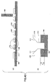
- FIG. 12 through FIG. 19 are views (part 1 through part 8) for explaining a manufacturing method of the solid-state image sensing device shown in FIG. 2, of the seventh embodiment of the present invention.
- a cutting process using a first cutting blade 145 having a cutting edge thickness "e" is applied to a transparent plate adhered on the main surface of a dicing tape 140 and the dicing tape 140, so that the transparent member is divided into plural transparent members 21 by a piercing hole 141 and plural grooves 148 are formed in the dicing tape 140.
- FIG. 12-(B) is an enlarged view of a part surrounded by a dotted line in FIG. 12-(A).
- An ultraviolet curing type adhesive tape may be used as the dicing tape 140, so that an adhesive force is reduced by irradiation of the ultraviolet rays.
- the transparent plate is pierced and cut by the first cutting blade 145 such as a diamond blade (diamond saw) rotated at high speed so that the piercing hole 141 is formed.
- the dicing tape 140 is cut to a depth "a" between the transparent member 21 and the solid-state image sensor 28 shown in FIG. 2, namely a height "a” of the space formed between the transparent member 21 and the solid-state image sensor 28, so that the groove 148 is formed.
- the transparent member 21 is, for example, made of a glass plate.
- the transparent plate is cut by the first cutting blade 145 so that the transparent member 21 has a configuration and an area corresponding to a light receiving area of the solid-state image sensor as a semiconductor element.
- the transparent plate on the dicing tape is cut in directions crossing at right angles to each other, namely X direction and Y direction, by the cutting blade so that plural transparent members 21 are separated in the X direction and Y direction.
- the configuration of the transparent member 21 is selected as corresponding to the configuration of the solid-state image sensor 28, the configuration of the light receiving area of the solid-state image sensor 29, the way of use of the semiconductor device 20, or the like. Accordingly, the cutting configuration of the transparent member 21 is selected based on this.
- shock-absorbing part material a material of the shock-absorbing member 100 (hereinafter "shock-absorbing part material”) 147.
- a dam 142 is provided on the dicing tape 140 so as to surround the arrangement of the transparent member 21 in advance and therefore the shock-absorbing part material 147 is provided at the circumferential side surface (edge surface) of the transparent member 21 situated at the outermost of the arrangement of the transparent member 21.
- the piercing hole 141 and the groove 148 are filled with the shock-absorbing part material 147. Details of the shock-absorbing part material 147 are as discussed above.
- FIG. 13-(B) is an enlarged view of a part surrounded by a dotted line in FIG. 13-(A).
- FIG. 14 shows this state. As shown in FIG. 14, at an inside of the dam 142, the surrounding area of the transparent members 21 divided in plural is filled with the shock-absorbing part material 147.
- FIG. 13-(A) shows a state where the groove 148 is not formed at a surface side facing the dam 142 of the transparent member 21 situated outermost. This is because it is assumed that the outermost transparent member has a measurement or configuration not being used. If the outermost transparent member has a measurement or configuration capable of being used, groove 148 is formed at a surface side facing the dam 142 of the transparent member 21 situated outermost. This is applied to other embodiment shown in FIG. 24, FIG. 30, FIG. 33, FIG. 37, FIG. 43, or the like.
- the shock-absorbing part material 147 shown in FIG. 14 is cut by using a second cutting blade 155 having a having a cutting edge thickness "m" less than the first cutting blade 145.
- the shock-absorbing part material 147 (see FIG. 14) with which the piercing hole 141 and the groove 148 are filled is cut by using the second cutting blade 155, so that the shock-absorbing member 100 is formed at the circumferential side surface of the transparent member 21.
- the second cutting blade 155 reaches inside of the dicing tape 140.
- ultraviolet rays UV are irradiated from a lower surface side of the dicing tape 140.
- FIG. 17-(A) is a plan view of the transparent member 21 obtained by the processes shown in FIG. 11 through FIG. 16.
- FIG. 17-(B) is a cross-sectional view taken along line X-X' of FIG. 17-(A).
- the circumferential side surface of the transparent member 21 is covered with the shock-absorbing member 100.
- the shock-absorbing member 100 has a length (thickness) greater than a length (thickness) of the transparent member 21 by a length (thickness) corresponding to the separated length "a" (see FIG. 2) between the transparent member 21 and the solid-state image sensor 28.
- the transparent member 21 whose circumferential side surface is covered with the shock-absorbing member 100 is provided and fixed on the light receiving surface of the solid-state image sensor 28 mounted on the wiring board 24.
- the solid-state image sensor 28 is fixed on the wiring board by the bonding member 26 in advance.
- the transparent member 21 is fixed on the light receiving surface of the solid-state image sensor 28 by heating and melting a contact part of the shock-absorbing member 100 and the solid-state image sensor 28 or by applying another epoxy group adhesive to the contact part.
- the transparent member 21 is provided on the solid-state image sensor 28 in an example shown in FIG. 18, the present invention is not limited to this.
- the transparent member 21 may be provided on the wafer state solid-state image sensor 28.
- an electrode of the solid-state image sensor 29 is connected to an electrode on the wiring board 24 by the bonding wire 27.
- the solid-state image sensing device 20 is formed via a sealing process using the sealing resin 25, a process for forming an outside connection terminal on another main surface of the wiring board 24, and a packing process using the sealing resin 25 (not shown).
- the degree of freedom to set the length and width (thickness) of the shock-absorbing member 100 is high. That is, the width (thickness) of the shock-absorbing member 100 can be selected by changing a cut amount "a" of the dicing tape 140 by the first cutting blade 145 shown in FIG. 12 in the manufacturing process of the solid state image sensing device 20.
- a covering thickness of the shock-absorbing member 100 that is, a thickness at which the external circumferential side surface of the transparent member 21 is covered, can be selected by changing a cutting edge of the first cutting blade 145 cutting in the dicing tape 140 and/or a cutting edge of the second cutting blade cutting off the dicing tape 140.
- shock-absorbing member 100 is to be manufactured by using a well-known printing technique, it is necessary to form a printing mask. In addition, it is necessary to form a new printing mask whenever the size of the solid-state image sensor is changed. This causes an increase of the manufacturing cost.
- the manufacturing method of the solid-state image sensing device 20 of this embodiment it is possible to easily form the light receiving part proper for various kinds of solid-state image sensors by changing the cutting blade 145 or 155 and/or the dicing condition.
- FIG. 20 through FIG. 28 are views (part 1 through part 9) for explaining a manufacturing method of the solid-state image sensing device 40 shown in FIG. 4, of the seventh embodiment of the present invention.
- the dicing tape 140 same as the tape used in the above-discussed in the seventh embodiment is cut to a designated depth by using a third cutting blade 165 having a cutting edge thickness "b" so that the groove forming parts 161 crossing in the X and Y directions are formed.
- FIG. 20-(B) is an enlarged view of a part surrounded by a dotted line in FIG. 20-(A).
- a cutting depth of the dicing tape 140 by the third cutting blade 165 is the same as a height "a" of the spacer 110 provided between the transparent member 21 and the solid-state image sensor 28, namely a height of a space formed between the transparent member 21 and the solid-state image sensor 28.
- the transparent plate 200 is adhered on the dicing tape 140 where the grooves 161 are formed so that the grooves 161 are covered by the transparent plate 200.
- FIG. 21-(B) is an enlarged view of a part surrounded by a dotted line in FIG. 21-(A).
- the transparent plate 200 is cut, as corresponding to the grooves 161, by using the fourth cutting blade 175 whose cutting edge thickness "c" is less than the cutting edge thickness "b" of the third cutting blade 165.
- FIG. 22-(B) is an enlarged view of a part surrounded by a dotted line in FIG. 22-(A).
- the transparent plate 200 shown in FIG. 21 is cut and separated by the fourth cutting blade 175 so that plural cutting members 21 are formed.
- the piercing holes 171 of the dicing tape 140 are formed above the grooves 161.
- the groove 161 is filled with a spacer material 167 forming the spacer 110 and cured.
- a spacer material 167 forming the spacer 110 and cured.
- an epoxy group adhesive or the like can be used as the spacer material 167.
- FIG. 23-(B) is an enlarged view of a part surrounded by a dotted line in FIG. 23-(A).
- a filling amount of the spacer material 167 is selected so that the spacer material 167 fills to a height contacting a lower surface of the transparent member 21.
- the dam 142 for filling the groove 171 with the shock-absorbing part material 147 is provided on the dicing tape and around the arrangement of the transparent member 21. After that, the piercing hole 171 is filled with the shock-absorbing part material 147. Details of the shock-absorbing part material 147 are as discussed above.
- FIG. 24-(B) is an enlarged view of a part surrounded by a dotted line in FIG. 24-(A).
- the shock-absorbing part material 147 fills to a height the same as an upper surface of the transparent member 21 and is cured.
- FIG. 25 shows a state where the shock-absorbing part material 147 fills in the grooves 171.
- the surrounding area of the transparent members 21 separated in X and Y directions are covered with the shock-absorbing part material 147 filling in the groove 171.
- the shock-absorbing part material 147 and the spacer member 167 are cut by using the fifth cutting blade 185 whose cutting edge thickness "d" is less than the cutting edge thickness "c" of the fourth cutting blade 175.
- FIG. 26-(B) is an enlarged view of a part surrounded by a dotted line in FIG. 26-(A).
- a cutting process using the fifth cutting blade 185 is implemented so that the shock-absorbing part material 147 filling in the piercing hole 171 is pierced, the spacer material 167 filling in the groove 161 is pierced, and the dicing tape 140 is cut.
- the shock-absorbing member 100 is formed on the circumferential side surface of the transparent member 21 and the spacer 11 continuing from the shock-absorbing member 100 is formed.
- ultraviolet rays UV are irradiated from a lower surface side of the dicing tape 140.
- the circumferential side surface (edge surface) of the transparent member 21 is covered with the shock-absorbing member 100, and a spacer 111 having a thickness "a" is provided on a circumferential edge part of another main surface of the transparent member 21.
- the transparent member 21 is provided and fixed on the light receiving surface of the solid-state image sensor 28 by heating and melting a contact part of the spacer 111 and the solid-state image sensor 28 or by applying another epoxy group adhesive to the contact part.
- an electrode of the solid-state image sensor 29 is connected to an electrode on the wiring board 24 by the bonding wire 27.
- the solid-state image sensing device 40 is formed via a sealing process using the sealing resin 25, a process for forming an outside connection terminal on another main surface of the wiring board 24, and a packing process using the sealing resin 25 (not shown).
- the height of the spacer 111 can be selected by changing a dicing condition, namely a cut amount "a" of the dicing tape 140 by the third cutting blade 165 shown in FIG. 20 in the manufacturing process of the solid state image sensing device 40.
- thickness of the shock-absorbing member 100 and the spacer 111 can be selected by changing a cutting edge of the fifth cutting blade 185 shown in FIG. 26.
- a dicing condition namely, a cutting length or a cutting position where the transparent member 21 and the dicing tape 140 are diced by using the fourth cutting blade 175 shown in FIG. 22.
- the manufacturing method of the solid-state image sensing device 40 of this embodiment it is possible to easily form the shock-absorbing member and the transparent member having the spacer proper for various kinds of solid-state image sensors at low cost by changing the cutting blade and/or the dicing condition.
- the shock-absorbing member 100 is provided between the sealing resin 25 and the circumferential side surface (edge surface) of the transparent member 21, and the spacer 111 is provided on the upper surface of the solid-state image sensor 28.
- the shock-absorbing member having a Young's modulus different from the Young's modulus of the shock-absorbing member 100 provided between the sealing resin 25 and the circumferential side surface (edge surface) of the transparent member 21 is provided as the spacer 113 between the transparent member 21 and the solid-state image sensor 20.
- the solid-state image sensing device 70 shown in FIG. 6 by implementing the manufacturing method of the seventh embodiment of the present invention wherein the material having the Young's modulus different from the Young's modulus of the shock-absorbing member 100 is used as a material of the spacer 113 instead of the spacer material 167 being a material of the spacer 110.
- FIG. 3 a manufacturing method of the solid-state image sensing device 30 shown in FIG. 3 is discussed as a ninth embodiment of the present invention with reference to FIG. 20 through FIG. 23 and FIG. 29 through FIG. 32.
- the dicing tape 140 is cut at a designated depth by using the third cutting blade 165 having the cutting edge thickness "b" so that plural groove forming parts 161 are formed.
- FIG. 20-(B) is an enlarged view of a part surrounded by a dotted line in FIG. 20-(A).
- the cutting depth of the dicing tape 140 by the third cutting blade 165 is the same as a height "a" of the spacer 110 provided between the transparent member 21 and the solid-state image sensor 28, namely a height of a space formed between the transparent member 21 and the solid-state image sensor 28.
- the transparent plate 200 is adhered on the dicing tape 140 where the grooves 161 are formed so that the grooves 161 are covered by the transparent plate 200.
- FIG. 21-(B) is an enlarged view of a part surrounded by a dotted line in FIG. 21-(A).
- the transparent plate 200 is cut, as corresponding to the grooves 161, by using the fourth cutting blade 175 whose cutting edge thickness "c" is less than the cutting edge thickness "b" of the third cutting blade 165.
- FIG. 22-(B) is an enlarged view of a part surrounded by a dotted line in FIG. 22-(A).
- the transparent plate 200 shown in FIG. 21 is cut and separated by the fourth cutting blade 175 so that plural cutting members 21 are formed.
- the piercing holes 171 of the dicing tape 140 are formed above the grooves 161.
- the groove 161 is filled with a spacer material 167 forming the spacer 110 and cured.
- a spacer material 167 forming the spacer 110 and cured.
- an epoxy group adhesive or the like can be used as the spacer material 167.
- FIG. 23-(B) is an enlarged view of a part surrounded by a dotted line in FIG. 23-(A).
- a filling amount of the spacer material 167 is selected so that the spacer material 167 fills to height contacting a lower surface of the transparent member 21.
- the piercing hole 171 is pierced again by the fourth cutting blade 175 shown in FIG. 22 so that the spacer material filling in the groove 161 is cut.
- FIG. 29-(B) is an enlarged view of a part surrounded by a dotted line in FIG. 29-(A).
- a cutting process is implemented so as to reach the bottom surface of the groove 161 situated in the dicing tape 140, so that the spacer material 167 is cut and separated as corresponding to each of the transparent member 21.
- a groove having a width of "c" the same as the width of the piercing hole 171 is formed in the groove 161 having a width of "b” and the spacer material 167 is provided on the inner surface of the groove.
- the spacer material 167 is positioned in the vicinity of the external circumferential part of the transparent member 21 at the other main surface of the transparent member 21.
- the dam 142 for filling the groove 171 with the shock-absorbing part material 147 is provided on the dicing tape 140 and around of the arrangement of the transparent member 21.
- the piercing part 171 is filled with the shock-absorbing part material 147.
- the details of the shock-absorbing part material 147 are as discussed above.
- FIG. 30-(B) is an enlarged view of a part surrounded by a dotted line in FIG. 30-(A).
- the shock-absorbing part material 147 fills in the piercing part 171 and the groove 161 and is cured. At this time, in the groove 161, the spacer 110 made of the spacer material 167 comes in contact with the circumference of the shock-absorbing part material 147.
- the shock-absorbing part material 147 filling in the piercing hole 171 and the groove 161 are cut by using the fifth cutting blade 185 shown in FIG. 29 whose cutting edge thickness "d" is less than the cutting edge thickness "c" of the fourth cutting blade 175.
- FIG. 31-(B) is an enlarged view of a part surrounded by a dotted line in FIG. 31-(A).
- ultraviolet rays UV are irradiated from a lower surface side of the dicing tape 140.
- the circumferential side surface (edge surface) of the transparent member 21 is covered with the shock- absorbing member 100, and a spacer 111 having a thickness "a" and an extending part (wide width part) of the shock-absorbing member 100 are provided on a circumferential edge part of another main surface of the transparent member 21.
- the transparent member 21 is provided and fixed on the light receiving surface of the solid-state image sensor 28 by heating and melting a contact part of the spacer 111 and the solid-state image sensor 28 or by applying another epoxy group adhesive to the contact part.
- an electrode of the solid-state image sensor 29 is connected to an electrode on the wiring board 24 by the bonding wire 27.
- the solid-state image sensing device 30 is formed via a sealing process using the sealing resin 25, a process for forming an outside connection terminal on another main surface of the wiring board 24, and a packing process using the sealing resin 25 (not shown).
- FIG. 5 a manufacturing method of the solid-state image sensing device 50 shown in FIG. 5 is discussed as a tenth embodiment of the present invention with reference to FIG. 20 through FIG. 25 and FIG. 33 through FIG. 35.
- the shock-absorbing member having a Young's modulus the same as the Young's modulus of the shock-absorbing member 101 provided between the sealing resin 25 and the circumferential side surface (edge surface) of the transparent member 21 is provided as the spacer between the transparent member 21 and the sealing resin 25.
- the dicing tape 140 is cut at a designated depth by using the third cutting blade 165 having the cutting edge thickness "b" so that plural groove forming parts 161 are formed.
- FIG. 20-(B) is an enlarged view of a part surrounded by a dotted line in FIG. 20-(A).
- the cutting depth of the dicing tape 140 by the third cutting blade 165 is the same as a height "a" of the spacer 110 provided between the transparent member 21 and the solid-state image sensor 28, namely a height of a space formed between the transparent member 21 and the solid-state image sensor 28.
- the transparent plate 200 is adhered on the dicing tape 140 where the grooves 161 are formed so that the grooves 161 are covered by the transparent plate 200.
- FIG. 21-(B) is an enlarged view of a part surrounded by a dotted line in FIG. 21-(A).
- the transparent plate 200 is cut, as corresponding to the grooves 161, by using the fourth cutting blade 175 whose cutting edge thickness "c" is less than the cutting edge thickness "b" of the third cutting blade 165.
- FIG. 22-(B) is an enlarged view of a part surrounded by a dotted line in FIG. 22-(A).
- the transparent plate 200 shown in FIG. 21 is cut and separated by the fourth cutting blade 175 so that plural cutting members 21 are formed.
- the piercing holes 171 of the dicing tape 140 are formed above the grooves 161.
- a dam 142 for being filled with the shock-absorbing part material 147 is provided on the dicing tape 140 so as to surround the arrangement of the transparent member 21.
- the groove 161 and the piercing hole 141 are concurrently (continuously) filled with the shock-absorbing part material 171 and the shock-absorbing part material 171 is cured.
- FIG. 33-(B) is an enlarged view of a part surrounded by a dotted line in FIG. 33-(A).
- the shock-absorbing part material 171 fills the piercing hole 171 and the groove 161 so as to reach the upper surface of the piercing hole 171, namely at a height the same as the upper surface of the transparent member 21.
- the shock-absorbing part material 147 is cut by using the fifth cutting blade 185 whose cutting edge thickness "d" is less than the cutting edge thickness "c" of the fourth cutting blade 175.
- FIG. 34-(B) is an enlarged view of a part surrounded by a dotted line in FIG. 34-(A).
- a cutting process using the fifth cutting blade 185 is implemented so that the shock-absorbing part material 147 filling in the piercing hole 171 and the groove 161 is pierced and the dicing tape 140 is cut.
- the spacer material 167 filling in the groove 161 forms the shock-absorbing member 100 situated on the side surface circumference of the transparent member 21 and forms the spacer situated on another main surface of the transparent member 21.
- ultraviolet rays UV are irradiated from a lower surface side of the dicing tape 140.
- the circumferential side surface (edge surface) of the transparent member 21 is covered with the shock-absorbing member 100, and a spacer 112 having a thickness "a" and an extending part (wide width part) of the shock-absorbing member 100 are provided on a circumferential edge part of another main surface of the transparent member 21.
- the shock-absorbing member 100 and the spacer 112 are formed in a body.
- the transparent member 21 is provided and fixed on the light receiving surface of the solid-state image sensor 28 by heating and melting a contact part of the spacer 111 and the solid-state image sensor 28 or by applying another epoxy group adhesive to the contact part.
- an electrode of the solid-state image sensor 29 is connected to an electrode on the wiring board 24 by the bonding wire 27.
- the solid-state image sensing device 50 shown in FIG. 5 is formed via a sealing process using the sealing resin 25, a process for forming an outside connection terminal on another main surface of the wiring board 24, and a packing process using the sealing resin 25 (not shown).
- the shock-absorbing member 100 provided between the circumferential side surface (edge surface) of the transparent member 21 and the sealing resin 25 and the spacer 112 provided between the transparent member 21 and the solid-state image sensor 20 are made of the same material and formed in a body. Therefore, it is possible to reduce the number of processes and the cost for manufacturing the solid-state image sensing device 50.
- FIG. 7 a manufacturing method of the solid-state image sensing device 70 shown in FIG. 7 is discussed as an eleventh embodiment of the present invention with reference to FIG. 12, FIG. 13, and FIG. 36 through FIG. 39.
- the first shock-absorbing member 100 and the second shock-absorbing member 101 whose Young's modulus is different from that of the first shock-absorbing member 100 are between the sealing resin 25 and a circumferential side surface (edge surface) of the transparent member 21.
- a cutting process using a first cutting blade 145 having a cutting edge thickness "e" is applied to a transparent plate adhered on the main surface of a dicing tape 140 and the dicing tape 140, so that the transparent member is divided into plural transparent members 21 by piercing holes 141 and plural grooves 148 are formed in the dicing tape 140.
- FIG. 12-(B) is an enlarged view of a part surrounded by a dotted line in FIG. 12-(A).
- the transparent plate is pierced and cut by the first cutting blade 145 such as a diamond blade (diamond saw) rotated at high speed so that the piercing hole 141 is formed.
- the dicing tape 140 is cut to a separate depth "a" between the transparent member 21 and the solid-state image sensor 28 shown in FIG. 2, namely a height "a” of the space formed between the transparent member 21 and the solid-state image sensor 28, so that the groove 148 is formed.
- shock-absorbing part material a material of the shock-absorbing member 100 (hereinafter "shock-absorbing part material”) 147.
- a dam 142 is provided on the dicing tape 140 so as to surround the arrangement of the transparent member 21 in advance and therefore the shock-absorbing part material 147 is provided at the circumferential side surface (edge surface) of the transparent member 21 situated at the outermost of the arrangement of the transparent member 21.
- the piercing hole 141 and the groove 148 are filled with the shock-absorbing part material 147. Details of the shock-absorbing part material 147 are as discussed above.
- FIG. 13-(B) is an enlarged view of a part surrounded by a dotted line in FIG. 13-(A).
- the shock-absorbing part material 147 filling in the groove 141 is cut by using the sixth cutting blade 235 whose cutting edge thickness "f" is less than the cutting edge thickness of the first cutting blade 145.
- FIG. 36-(B) is an enlarged view of a part surrounded by a dotted line in FIG. 36-(A).
- the circumferential side surface (edge surface) of the transparent member 21 and the inside surface of the groove 148 formed in the dicing tape 140 are covered with the first shock-absorbing part material 100.
- a second groove 190 having a width "f" is formed between the first shock-absorbing part materials 100 neighboring each other.
- the second groove 190 is filled with a material of the second shock-absorbing member (hereinafter "second shock-absorbing part material”) 197.
- FIG. 37-(B) is an enlarged view of a part surrounded by a dotted line in FIG. 37-(A).
- the second shock-absorbing part material 197 filling in the second groove 190 is cured. Details of the shock-absorbing part material 147 and second shock-absorbing part material 197 are as discussed above.
- the second shock-absorbing part material 197 is cut by using the seventh cutting blade 195 whose cutting edge thickness "g" is less than the cutting edge thickness of the sixth cutting blade 235.
- FIG. 38-(B) is an enlarged view of a part surrounded by a dotted line in FIG. 38-(A).
- a cutting process using the seventh cutting blade 195 is implemented so that the second shock-absorbing part material 197 filling in the second groove 195 is pierced and the dicing tape 140 is cut, and thereby the second shock-absorbing part 101 is formed.
- ultraviolet rays UV are irradiated from a lower surface side of the dicing tape 140.
- the circumferential side surface (edge surface) of the transparent member 21 is covered with the first shock-absorbing member 100 and the second shock-absorbing member 101, and a double extending part (wide width part) having thickness "a" of the shock-absorbing members 100 and 101 are provided on a circumferential edge part of another main surface of the transparent member 21.
- the transparent member 21 is provided and fixed on the light receiving surface of the solid-state image sensor 28 by heating and melting a contact part of the spacer 111 and the solid-state image sensor 28 or by applying another epoxy group adhesive to the contact part.
- an electrode of the solid-state image sensor 29 is connected to an electrode on the wiring board 24 by the bonding wire 27.
- the solid-state image sensing device 50 shown in FIG. 5 is formed via a sealing process using the sealing resin 25, a process for forming an outside connection terminal on another main surface of the wiring board 24, and a packing process using the sealing resin 25 (not shown).
- the shock-absorbing member 100 is not provided between the sealing resin 25 and the circumferential side surface (edge surface) of the transparent member 21. Instead, a groove-shaped air space 102 is formed along the circumferential side surface (edge surface) of the transparent member 21 between the sealing resin 25 and the circumferential side surface (edge surface) of the transparent member 21.
- the manufacturing method of the solid-state image sensing device 80 is a modified method of the manufacturing method of the solid-state image sensing device 40 that is the eighth embodiment of the present invention.
- the piercing hole in the process shown in FIG. 24, the piercing hole is filled with the shock-absorbing part material 147.
- the piercing hole 171 is filled with the resist 300 and the resist 300 is cured.
- the same processes as the processes of the eighth embodiment are applied.
- the resist 300 is removed by a solvent.
- the groove-shaped air space 102 is formed between the sealing resin 25 and the circumferential side surface (edge surface) of the transparent member 21.
- the manufacturing method of this embodiment it is possible to form the solid-state image sensing device 80 at low cost by using the cutting blades having different cutting edge widths and/or changing the dicing condition.
- the second shock-absorbing part material 102 provided in the solid-state image sensing device 70 shown in FIG. 7 is not provided. Instead, groove-shaped air space 103 is formed between the sealing resin 25 and the shock-absorbing part material 100.
- the manufacturing method of the solid-state image sensing device 90 is a modified method of the manufacturing method of the solid-state image sensing device 70 that is the eleventh embodiment of the present invention.
- the second groove 190 is filled with the shock-absorbing part material 197 being a material of the second shock-absorbing member 102.
- a resist fills in the second groove 190 and is cured.
- the same processes as the processes of the eleventh embodiment are applied.
- the resist 301 is removed by a solvent.
- the air space 103 is formed between the sealing resin 25 and the shock-absorbing part material 100 provided on the circumferential side surface (edge surface) of the transparent member 21.
- the manufacturing method of this embodiment it is possible to form the solid-state image sensing device 90 at low cost by using the cutting blades having different cutting edge widths and/or changing the dicing condition.
- an external circumferential side surface of the transparent member 210 is tilted upward toward the center of the transparent member 210.
- the shock-absorbing member 100 is provided along the inclination of the transparent member 210 between the sealing resin 25 and the transparent member 210.
- a transparent plate, which is adhered on the dicing tape 140, and the dicing tape 140 are cut by the first dicing blade at a designated depth so that plural transparent members 210 are formed.
- the grooves 148 reaching into the dicing tape 140 are formed at the circumference of the transparent members 210.
- the transparent member 210 is formed, before or after cutting by the first cutting blade, the transparent member 210 is cut as corresponding to the groove 148 by using another cutting blade (not shown) wherein the cutting surface is an inclination surface (taper), so that a taper part 211 is formed on the circumferential side surface (edge surface) of the transparent member 210.
- the depth of the taper part 211 does not reach from the surface to the bottom surface of the transparent member 210.
- a cutting part by the cutting blade 145 is formed at a lower part of the transparent member 210, namely in the vicinity of the dicing tape 140.
- FIG. 42-(A) shows a state where the taper is not formed at the external circumferential part of the transparent member situated at an outermost past of the arrangement of the transparent members 210.
- the outermost transparent member has a measurement or configuration capable for being used, a taper is formed at the external circumferential part of the transparent member situated at an outermost past of the arrangement of the transparent members 210.
- FIG. 42-(B) is an enlarged view of a part surrounded by a dotted line in FIG. 42-(A).
- the transparent plate is pierced and cut by the first cutting blade 145 so that the piercing hole 215 is formed.
- the dicing tape 140 is cut at a separate distance "a" between the transparent member 210 and the solid-state image sensor 28 shown in FIG. 10, namely a height "a” of the space formed between the transparent member 210 and the solid-state image sensor 28, so that the groove 148 is formed.
- the taper 211 is formed on the circumferential side surface (edge surface) of the transparent member 210, an upper part of the piercing hole 215 is opened larger than a lower part of the piercing hole 215.
- a dam 142 is provided on the dicing tape 140 so as to surround the arrangement of the transparent members 210 in advance. After that, the piercing hole 215 and the groove 148 are filled with the shock-absorbing part material 147.
- FIG. 43-(B) is an enlarged view of a part surrounded by a dotted line in FIG. 43-(A).
- the shock-absorbing part material 147 fills in the piercing hole 215 and the groove 148 at a height the same as an upper surface of the transparent member 210 and is cured.
- the surface part of the shock-absorbing part material 147 is cut by an eighth cutting blade 255 wherein a cutting edge thickness (width) of the eighth cutting blade 225 is smaller than that of the first cutting blade 145 and a taper having the same inclination angle as the taper part 211 of the transparent member 210 is formed at a head end of the eighth cutting blade 225.
- FIG. 44-(B) is an enlarged view of a part surrounded by a dotted line in FIG. 44-(A).
- a V-shaped taper groove 212 is formed in the substantially center in the upper part of the shock-absorbing part material 147.
- the shock-absorbing part material 147 is cut by using the second cutting blade 155 whose cutting edge thickness is less than the cutting edge thickness of the first cutting blade 145.
- FIG. 45-(B) is an enlarged view of a part surrounded by a dotted line in FIG. 45-(A).
- a cutting process using the second cutting blade 155 is implemented so that the shock-absorbing part material 147 (See FIG. 44) filling in the groove 141 is pierced and the dicing tape 140 is cut.
- ultraviolet rays UV are irradiated from a lower surface side of the dicing tape 140.
- the circumferential side surface (edge surface) including the inclination surface of the transparent member 210 is covered with the shock-absorbing member 104, and an extending part (wide width part) of the shock-absorbing member 104 is provided on a circumferential edge part of another main surface of the transparent member 21.
- the transparent member 210 is provided and fixed on the light receiving surface of the solid-state image sensor 28 by heating and melting a contact part of the spacer 111 and the solid-state image sensor 28 or by applying another epoxy group adhesive to the contact part.
- an electrode of the solid-state image sensor 29 is connected to an electrode on the wiring board 24 by the bonding wire 27.
- the solid-state image sensing device 70 shown in FIG. 7 is formed via a sealing process using the sealing resin 25, a process for forming an outside connection terminal on another main surface of the wiring board 24, and a packing process using the sealing resin 25 (not shown).
- the manufacturing method of this embodiment it is possible to form the solid-state image sensing device 120 at low cost by using the cutting blades having different cutting edge widths and/or changing the dicing condition.
- shock-absorbing member 104 along the circumferential side surface (edge surface) of the transparent member 210 by using the cutting blade wherein an inclination (taper) is formed at the head end.
- materials of the transparent member 21 or 210 and the solid-state image sensor 28 may be selected so that the coefficient of thermal expansion of the transparent member 21 or 210 is the same as the coefficient of thermal expansion of the solid-state image sensor 28.
- the spacer 110 provided between the transparent member 21 or 210 and the solid-state image sensor 28 is made of, for example, an adhesive, if the coefficient of thermal expansion of the transparent member 21 or 210 is different from the coefficient of thermal expansion of the solid-state image sensor 28, stress is concentrated on the adhesive, namely the spacer 110, so that the adhesive may be peeled off.
- the solid-state image sensing device is explained as an example of the semiconductor device of the present invention
- the solid-state image sensor is explained as an example of the semiconductor element forming the semiconductor device of the present invention.
- the present invention is not limited to this.
- the semiconductor element is not limited to the solid-state image sensor such as an image sensor but may be, for example, a fingerprint sensor using glass.
- the semiconductor device is not limited to the semiconductor devices of the above-mentioned embodiments.
- the present invention can be applied to a semiconductor device such as an optical module or Erasable Programmable Read Only Memory (EPROM).
- EPROM Erasable Programmable Read Only Memory
Abstract
Description
- The present invention generally relates to semiconductor devices and manufacturing methods of the same, and more specifically, to a semiconductor device packaged or forming a module by sealing a semiconductor element and a manufacturing method of the same.
- A solid-state image sensing device, formed by packaging and modularizing a solid-state image sensor with a transparent member such as glass, a wiring board, a wiring connecting the solid-state image sensor and the wiring board, sealing resin, and others, is well-known. Here, the solid-state image sensing device is, for example, an image sensor such as a Charge Couple Device (CCD), or Complementary Metal Oxide Semiconductor (CMOS).
- FIG. 1 is a cross-sectional view of a related art solid-state image sensing device.
- Referring to FIG. 1, a solid-state
image sensing device 10 has a structure where a solid-state image sensor 8 is mounted on awiring board 4 having a lower surface whereplural bumps 2 are formed, via a die bonding member 6. A large number ofmicro lenses 9 are provided on an upper surface of the solid-state image sensor 8. The solid-state image sensor 8 is electrically connected to thewiring board 4 by abonding wire 7. - In addition, a
transparent member 1 such as glass is mounted above the solid-state image sensor 8 via aspace 3. Parts of the solid-state image sensor 8 and thewiring board 4 where thebonding wires 7 are provided, external circumferential parts of thetransparent member 1, and side parts of thespacers 3 are sealed by sealing resin 5. - Thus, the solid-
state image sensor 8 is sealed by thetransparent member 1 and the sealing resin 5. SeeJapan Laid-Open Patent Application Publications No. 62-67863 No 2000-323692 No. 2002-16194 - However, coefficients of thermal expansion of members forming the solid-state
image sensing device 10 shown in FIG. 1 are different from each other. For example, the coefficient of thermal expansion of silicon (Si) used as the solid-state image sensor 8 is 3×10⁻⁶/°C, the coefficient of thermal expansion of glass used as thetransparent member 1 is 7X10⁻⁶/°C, the coefficient of thermal expansion of the sealing resin 5 is 8x10⁻⁶/°C, and the coefficient of thermal expansion of thewiring board 4 is 16x10-6/°C. - In addition, for example, the temperature inside of a reflow hearth in a reflow process for mounting a package such as a camera module on the
wiring board 4 reaches around 260 °C. Heat is applied as a reliability test of the solid-stateimage sensing device 10. Furthermore, in normal use of the solid-stateimage sensing device 10, the solid-stateimage sensing device 10 may be put under atmospheric conditions wherein the temperature in summer may be higher than 80 °C. - Accordingly, under the atmospheric conditions wherein such a temperature change is made, the members may expand or contract by heat due to the difference of the coefficients of thermal expansion of the members, so that the
transparent member 1 may receive stress from the sealing resin 5 and/or thewiring board 4. As a result of this, an interface of thetransparent member 1 and the sealing resin 5, shown by a dotted line in FIG. 1, may peel off, or thetransparent member 1 or the solid-stateimage sensing device 10 may be damaged. - Glass and others used as the
transparent member 1 are strong against compression but weak (may be broken) against tension. Therefore, if the transparent member receives tension stress due to the difference of the coefficients of thermal expansion of the sealing resin 5 or thewiring board 4 and thetransparent member 1, thetransparent member 1 may be broken. - As discussed above, since the coefficient of thermal expansion of the
wiring board 4 is greater than the coefficients of thermal expansion of thetransparent member 1 and the sealing resin 5, thetransparent member 1 and the sealing resin 5 may be pulled (tensioned) due to the thermal expansion of thewiring board 4. As a result of this, thetransparent member 4 may be broken. - Because of this, a ceramic board having a smaller coefficient of thermal expansion may be used as the
wiring board 4. However, the ceramic board is expensive and use of the ceramic board causes a high price of the solid-stateimage sensing device 10. - Similarly, in order to prevent the generation of the above-mentioned stress, the
wiring board 4 may be formed by the same material as thetransparent member 1 such as glass, and the solid-state image sensor 8 may be put between thetransparent member 1 such as glass or thewiring board 4 made of glass, so that the members having the same coefficients of thermal expansion may be provided at upper and lower part of the solid-state image sensor 8. However, this structure is not preferable because the wiring board made of glass is also relatively expensive. - In addition, an air part is formed between the
transparent member 1 and the solid-state image sensor 8 by thespacers 3 in the solid-stateimage sensing device 10 shown in FIG. 1. The air part contributes to a light condensing effect by themicro lens 9. -
Japan Laid-Open Patent Application Publications No. 2003-197656 No. 2003-163342 - Accordingly, it is a general object of the present invention to provide a novel and useful semiconductor device and manufacturing method of the same.
- Another and more specific object of the present invention is to provide a semiconductor device having high reliability whereby destruction of the semiconductor device or members forming the semiconductor device due to the stress generated based on the difference of the coefficients of thermal expansion of the members forming the semiconductor device may be prevented, and a manufacturing method of the semiconductor device.
- It is also an object of the present invention to provide a manufacturing method of a semiconductor device whereby the semiconductor device can be easily manufactured without preparing a specific apparatus or member which fits the size of the semiconductor device.
- The above object of the present invention is achieved by a semiconductor device, including:
- a semiconductor element,
- a transparent member separated from the semiconductor element by a designated length and facing the semiconductor element,
- a sealing member sealing an edge surface of the transparent member and an edge part of the semiconductor element, and
- a shock-absorbing member provided between the edge surface of the transparent member and the sealing member and easing a stress which the transparent member receives from the sealing member or the semiconductor element.
- The above object of the present invention is also achieved by a manufacturing method of a semiconductor device, the semiconductor device including a semiconductor element and a transparent member separated from the semiconductor element by a designated length and facing the semiconductor element, the manufacturing method including the steps of:
- a) forming a piercing part in the transparent member adhered on an adhesive tape and forming a groove by cutting a part of the adhesive tape corresponding to the piercing part,
- b) filling in the piercing part and the groove with a material of a shock-absorbing part configured to ease a stress in the transparent member, and curing the material of the shock-absorbing part,
- c) cutting the material of the shock-absorbing part provided in the piercing part and the groove, and
- d) peeling off the transparent member from the adhesive tape.
- Other objects, features, and advantages of the present invention will be come more apparent from the following detailed description when read in conjunction with the accompanying drawings.
-
- FIG. 1 is a cross-sectional view of a related art solid-state image sensing device;
- FIG. 2 is a cross-sectional view of a solid-state image sensing device of a first embodiment of the present invention;
- FIG. 3 is a cross-sectional view of a solid-state image sensing device of a first modified example of the first embodiment of the present invention;
- FIG. 4 is a cross-sectional view of a solid-state image sensing device of a second modified example of the first embodiment of the present invention;
- FIG. 5 is a cross-sectional view of a solid-state image sensing device of a third modified example of the first embodiment of the present invention;
- FIG. 6 is a cross-sectional view of a solid-state image sensing device of a fourth modified example of the first embodiment of the present invention;
- FIG. 7 is a cross-sectional view of a solid-state image sensing device of a second embodiment of the present invention;
- FIG. 8 is a cross-sectional view of a solid-state image sensing device of a third embodiment of the present invention;
- FIG. 9 is a cross-sectional view of a solid-state image sensing device of a fourth embodiment of the present invention;
- FIG. 10 is a cross-sectional view of a solid-state image sensing device of a fifth embodiment of the present invention;
- FIG. 11 is a cross-sectional view of a solid-state image sensing device of a sixth embodiment of the present invention;
- FIG. 12 is a view (part 1) for explaining a manufacturing method of the solid-state image sensing device shown in FIG. 2, of a seventh embodiment of the present invention;
- FIG. 13 is a view (part 2) for explaining a manufacturing method of the solid-state image sensing device shown in FIG. 2, of the seventh embodiment of the present invention;
- FIG. 14 is a view (part 3) for explaining a manufacturing method of the solid-state image sensing device shown in FIG. 2, of the seventh embodiment of the present invention;
- FIG. 15 is a view (part 4) for explaining a manufacturing method of the solid-state image sensing device shown in FIG. 2, of the seventh embodiment of the present invention;
- FIG. 16 is a view (part 5) for explaining a manufacturing method of the solid-state image sensing device shown in FIG. 2, of the seventh embodiment of the present invention;
- FIG. 17 is a view (part 6) for explaining a manufacturing method of the solid-state image sensing device shown in FIG. 2, of the seventh embodiment of the present invention;
- FIG. 18 is a view (part 7) for explaining a manufacturing method of the solid-state image sensing device shown in FIG. 2, of the seventh embodiment of the present invention;
- FIG. 19 is a view (part 8) for explaining a manufacturing method of the solid-state image sensing device shown in FIG. 2, of the seventh embodiment of the present invention;
- FIG. 20 is a view (part 1) for explaining a manufacturing method of the solid-state image sensing device shown in FIG. 4, of an eighth embodiment of the present invention;
- FIG. 21 is a view (part 2) for explaining a manufacturing method of the solid-state image sensing device shown in FIG. 4, of the eighth embodiment of the present invention;
- FIG. 22 is a view (part 3) for explaining a manufacturing method of the solid-state image sensing device shown in FIG. 4, of the eighth embodiment of the present invention;
- FIG. 23 is a view (part 4) for explaining a manufacturing method of the solid-state image sensing device shown in FIG. 4, of the eighth embodiment of the present invention;
- FIG. 24 is a view (part 5) for explaining a manufacturing method of the solid-state image sensing device shown in FIG. 4, of the eighth embodiment of the present invention;
- FIG. 25 is a view (part 6) for explaining a manufacturing method of the solid-state image sensing device shown in FIG. 4, of the eighth embodiment of the present invention;
- FIG. 26 is a view (part 7) for explaining a manufacturing method of the solid-state image sensing device shown in FIG. 4, of the eighth embodiment of the present invention;
- FIG. 27 is a view (part 8) for explaining a manufacturing method of the solid-state image sensing device shown in FIG. 4, of the eighth embodiment of the present invention;
- FIG. 28 is a view (part 9) for explaining a manufacturing method of the solid-state image sensing device shown in FIG. 4, of the eighth embodiment of the present invention;
- FIG. 29 is a view (part 1) for explaining a manufacturing method of the solid-state image sensing device shown in FIG. 3, of a ninth embodiment of the present invention;
- FIG. 30 is a view (part 2) for explaining a manufacturing method of the solid-state image sensing device shown in FIG. 3, of the ninth embodiment of the present invention;
- FIG. 31 is a view (part 3) for explaining a manufacturing method of the solid-state image sensing device shown in FIG. 3, of the ninth embodiment of the present invention;
- FIG. 32 is a view (part 4) for explaining a manufacturing method of the solid-state image sensing device shown in FIG. 3, of the ninth embodiment of the present invention;
- FIG. 33 is a view (part 1) for explaining a manufacturing method of the solid-state image sensing device shown in FIG. 5, of a tenth embodiment of the present invention;
- FIG. 34 is a view (part 2) for explaining a manufacturing method of the solid-state image sensing device shown in FIG. 5, of the ninth embodiment of the present invention;
- FIG. 35 is a view (part 3) for explaining a manufacturing method of the solid-state image sensing device shown in FIG. 5, of the ninth embodiment of the present invention;
- FIG. 36 is a view (part 1) for explaining a manufacturing method of the solid-state image sensing device shown in FIG. 7, of an eleventh embodiment of the present invention;
- FIG. 37 is a view (part 2) for explaining a manufacturing method of the solid-state image sensing device shown in FIG. 7, of the eleventh embodiment of the present invention;
- FIG. 38 is a view (part 3) for explaining a manufacturing method of the solid-state image sensing device shown in FIG. 7, of the eleventh embodiment of the present invention;
- FIG. 39 is a view (part 4) for explaining a manufacturing method of the solid-state image sensing device shown in FIG. 7, of an eleventh embodiment of the present invention;
- FIG. 40 is a view for explaining a manufacturing method of the solid-state image sensing device shown in FIG. 8, of a twelfth embodiment of the present invention;
- FIG. 41 is a view for explaining a manufacturing method of the solid-state image sensing device shown in FIG. 9, of a thirteenth embodiment of the present invention;
- FIG. 42 is a view (part 1) for explaining a manufacturing method of the solid-state image sensing device shown in FIG. 10, of a fourteenth eighth embodiment of the present invention;
- FIG. 43 is a view (part 2) for explaining a manufacturing method of the solid-state image sensing device shown in FIG. 10 of the fourteenth embodiment of the present invention;
- FIG. 44 is a view (part 3) for explaining a manufacturing method of the solid-state image sensing device shown in FIG. 10, of the fourteenth embodiment of the present invention;
- FIG. 45 is a view (part 4) for explaining a manufacturing method of the solid-state image sensing device shown in FIG. 10, of the fourteenth embodiment of the present invention; and
- FIG. 46 is a view (part 5) for explaining a manufacturing method of the solid-state image sensing device shown in FIG. 10, of the fourteenth embodiment of the present invention.
- A description is given below, with reference to the FIG. 2 through FIG. 46 of embodiments of the present invention.
- For the convenience of explanation, a description of a semiconductor device of an embodiment of the present invention is given with reference to FIG. 2 through FIG. 11, and then a description of a manufacturing method of the semiconductor device of an embodiment of the present invention is given with reference to FIG. 12 through FIG. 46.
- In the followings, a solid-state image sensing device is explained as an example of a semiconductor device of the present invention.
- First, a solid-state image sensing device of a first embodiment of the present invention is discussed with reference to FIG. 2. Here, FIG. 2 is a cross-sectional view of the solid-state image sensing device of the first embodiment of the present invention.
- Referring to FIG. 2, a solid-state
image sensing device 20 has a structure where asolid image sensor 28 as a semiconductor element is packaged (forms a module) with atransparent member 21, abonding wire 27, awiring board 24, sealingresin 25, and others. Thesolid image sensor 28 is sealed by thetransparent member 21 and the sealingresin 25. In other words, the solid-state image sensor 28 is mounted on thewiring board 24 having a lower surface where pluraloutside connection terminals 22 are formed, via adie bonding member 26. - A large number of micro lenses (light receiving lenses) 29 are provided on an upper surface of the solid-
state image sensor 28. An electrode of the solid-state image sensor 28 is electrically connected to an electrode of thewiring board 24 by abonding wire 27. - In addition, the
transparent member 21 is provided at an upper part of the solid-state image sensor 28 so as to be separated from the solid-state image sensor 28 at a designated distance "a". - Since the
transparent member 21 is separated from the solid-state image sensor 28 at a designated distance "a", an air part is formed between thetransparent member 21 and the solid-state image sensor 28. - Because of the difference of indexes of reflection between air and the
micro lens 29, light incident through thetransparent member 21 is effectively incident on a light receiving element (photo diode) formed on a main surface of the solid-state image sensor 28. - Silicon (Si), for example, can be used as a semiconductor substrate forming the solid-
state image sensor 28. Glass, transparent plastic, crystal, quartz, sapphire, or the like can be used as thetransparent member 21. However, the present invention is not limited to these examples. - The sealing
resin 25 is provided on a part where thebonding wires 27 are provided of the solid-state image sensor 28 and thewiring board 24 so that a top surface of the sealingresin 25 is situated as almost planar with an upper surface of thetransparent member 21. Here, the upper surface of thetransparent member 21 is opposite to a surface facing the solid-state image sensor 28. - Silicon group resin, acrylic resin, epoxy resin, or the like can be used as the sealing
resin 25. However, the present invention is not limited to these examples. - In this embodiment, under this structure, a shock-absorbing
member 100 is provided, in an area where themicro lens 29 is not provided on an upper surface of the solid-state image sensor 28, and between the sealingresin 25 and thetransparent member 21, that is, between the sealingresin 25 and an external circumferential side surface of thetransparent member 21. - A resin material having Young's modulus of approximately 0.1 through 10 GPa, such as epoxy resin, denatured polymer, or denatured silicon, may be used as the shock-absorbing
member 100. - When the shock-absorbing
member 100 is provided on the external circumferential surface of thetransparent member 21, the width (length in upper and lower directions in FIG. 2) of the shock-absorbingmember 100 is longer than the width (length in upper and lower directions in FIG. 2) of thetransparent member 21 and a designated amount of the shock-absorbingmember 100 projects to a side of the solid-state image sensor 28. As a result of this, it is possible to form a distance "a" between thetransparent member 21 and the solid-state image sensor 28. - The coefficient of thermal expansion of silicon (Si) used as the solid-
state image sensor 28 is 3x10⁻⁶/°C, the coefficient of thermal expansion of glass used as thetransparent member 21 is 7x10⁻⁶ /°C, the coefficient of thermal expansion of the sealingresin 25 is 8x10⁻⁶/°C, and the coefficient of thermal expansion of thewiring board 24 is 16x 10-6/°C. - Although there are differences of the coefficients of thermal expansion as discussed above, a designated stress, given from the sealing
resin 25 and thewiring board 24 to thetransparent member 21 due to the thermal expansion of thetransparent member 21, the sealingresin 25 and the solid-state image sensor 28 and the difference of the coefficients of thermal expansion of the members, can be eased and absorbed by the shock-absorbingmember 100. - Accordingly, it is possible to prevent the
transparent member 21 or the solid-stateimage sensing device 20 from being destroyed in a manufacturing process of, a testing step of, or use of the solid-stateimage sensing device 20. Thus, it is possible to improve the reliability of the solid-stateimage sensing device 20. - Next, a solid-state image sensing device of a first modified example of the first embodiment of the present invention is discussed with reference to FIG. 3. Here, FIG. 3 is a cross-sectional view of a solid-state
image sensing device 30 of the first modified example of the first embodiment of the present invention. - Referring to FIG. 3, in the modified example, the shock-absorbing
member 100 is provided between the sealingresin 25 and thetransparent member 21, that is, between the sealingresin 25 and an external circumferential side surface of thetransparent member 21. In addition, aspacer 110 is provided on an area where themicro lens 29 is not provided of an upper surface of the solid-state image sensor 28. Thespacer 110 is provided from an inside of a projection part of the shock-absorbingmember 100 in a light receiving area direction of the solid-state image sensor 28. - The
spacer 110, as well as the projection part of the shock-absorbingmember 100, sets a distance "a" between thetransparent member 21 and the solid-state image sensor 28, so that an air part can be formed between thetransparent member 21 and the solid-state image sensor 28. As a result of this, it is possible to obtain a light condensing effect of themicro lens 29 formed on the solid-state image sensor 28 maximum. - An adhesive layer formed by, for example, epoxy group resin, can be used as the
spacer 110. However, the present invention is not limited to this example. - Next, a solid-state image sensing device of a second modified example of the first embodiment of the present invention is discussed with reference to FIG. 4. Here, FIG. 4 is a cross-sectional view of a solid-state
image sensing device 40 of the second modified example of the first embodiment of the present invention. - Referring to FIG. 4, only a
spacer 111 is provided on an area where themicro lens 29 is not provided of an upper surface of the solid-state image sensor 28. In other words, in this modified example, unlike the above-discussed embodiment or the modified example, the shock-absorbingmember 100 does not project from the lower surface of thetransparent member 21, and thespacer 111 is provided between thetransparent member 21 and the solid-state image sensor 28 and between the shock-absorbingmember 100 having the same width as thetransparent member 21 and the solid-state image sensor 28. - Under this structure, an air part can be formed between the
transparent member 21 and the solid-state image sensor 28 by thespacer 111. As a result of this, it is possible to obtain a maximum light condensing effect of themicro lens 29 formed on the solid-state image sensor 28. - Next, a solid-state image sensing device of a third modified example of the first embodiment of the present invention is discussed with reference to FIG. 5. Here, FIG. 5 is a cross-sectional view of a solid-state
image sensing device 50 of the third modified example of the first embodiment of the present invention. - Referring to FIG. 5, the same material as the shock-absorbing
member 100 is used as thespacer 112. In other words, a member made of a material the same as the shock-absorbingmember 100 provided between the sealingresin 25 and a circumferential side surface (edge surface) of thetransparent member 21 as thespacer 112 is provided between thetransparent member 21 and the solid-state image sensor 20. - As discussed above, there is a difference of the coefficients of thermal expansion between the solid-
state image sensor 28 and thetransparent member 21. Therefore, stress based on the difference of such coefficient of thermal expansion may be generated between the solid-state image sensor 28 and thetransparent member 21. - In this example, since the same material as the shock-absorbing
member 100 is used as thespacer 112 forming an air part between the solid-state image sensor 28 and thetransparent member 21, it is possible effectively prevent the destruction of thetransparent member 21 due to the stress from the solid-state image sensor 28. - Furthermore, since the same material as the shock-absorbing
member 100 provided between the circumferential side surface of thetransparent member 21 and the sealingresin 25 is used as thespacer 112 provided between thetransparent member 21 and the solid-state image sensor 28, it is possible to reduce the manufacturing cost of the solid-stateimage sensing device 50. - Next, a solid-state image sensing device of a fourth modified example of the first embodiment of the present invention is discussed with reference to FIG. 6. FIG. 6 is a cross-sectional view of a solid-state
image sensing device 60 of the fourth modified example of the first embodiment of the present invention. - Referring to FIG. 6, a
spacer 113 is made of a material having a Young's modulus different from that of the shock-absorbingmember 100 provided between the circumferential side surface (edge surface) of thetransparent member 21 and the sealingresin 25. - As discussed above, the difference of the coefficients of thermal expansion between the solid
state image sensor 28 and thetransparent member 21 is different from the difference of the coefficients of thermal expansion between the sealingresin 25 and thetransparent member 21. Therefore, if the differences of the coefficients of thermal expansion of the members are different from each other, amounts of the stress generated based on the differences of the coefficients of thermal expansion are different. - Thus, in this example, the shock-absorbing
member 100 is provided between the edge surface of thetransparent member 21 and the sealingresin 25. Thespacer 113 forming a space between the solid-state image sensor 28 and thetransparent member 21 is made of the material having the different Young's modulus of the shock-absorbingmember 100 provided. - Under this structure, even if the difference of the coefficients of thermal expansion between the solid
state image sensor 28 and thetransparent member 21 is different from the difference of the coefficients of thermal expansion between the sealingresin 25 and thetransparent member 21, it is possible to ease and absorb the stress generated due to the difference of the coefficients of thermal expansion between the members so that the destruction of thetransparent member 21 and others can be prevented. - Next, a solid-state image sensing device of a second embodiment of the present invention is discussed with reference to FIG. 7. Here, FIG. 7 is a cross-sectional view of a solid-state image sensing device of a fourth modified example of a second embodiment of the present invention.
- In the following explanations, parts that are the same as the parts shown in the above- referred drawings are given the same reference numerals, and explanation thereof is omitted.
- Referring to FIG. 7, in the solid-state
image sensing device 70 of the second embodiment, a second shock-absorbingmember 101 is provided at an external circumferential part of the shock-absorbing member 100 ("the first shock-absorbingmember 100" in the following explanation of this embodiment), namely between the sealingresin 25 and a circumferential side surface (edge surface) of thetransparent member 21. The Young's modulus of the second shock-absorbingmember 101 is different from that of the first shock-absorbingmember 100. - When the shock-absorbing
members transparent member 21, a width (length in upper and lower directions in FIG. 7) of the shock-absorbingmembers transparent member 21, and a designated amount of the shock-absorbingmembers state image sensor 28. As a result of this, it is possible to form a distance "a" between thetransparent member 21 and the solid-state image sensor 28. - A resin material having Young's modulus of approximately 0.1 through 10 GPa, such as epoxy resin, denatured polymer, or denatured silicon, may be used as the first and second shock-absorbing
members members 100, it is preferable to use a resin material having Young's modulus of approximately 0.1 GPa, such as denatured polymer, or denatured silicon, as the second shock-absorbingmembers 101. - In other words, it is preferable that the Young's modulus of the second shock-absorbing
members 101 be less than the Young's modulus of the first shock-absorbingmember 100. As discussed above, since the coefficient of thermal expansion of the sealingresin 25 is greater than the coefficient of thermal expansion of thetransparent member 21, the vicinity of the interface of the sealingresin 25 and thetransparent member 21 may receive a bigger stress. Hence, it is preferable that the second shock-absorbingmember 101 which may be easily deformed and has a Young's modulus less than the Young's modulus of the first shock-absorbingmember 100 be provided at a side of the sealingresin 25, namely a side where the big stress is generated due to the large coefficient of thermal expansion. - While two kinds of shock-absorbing members, that is the first and second shock-absorbing
members resin 25 and thetransparent member 21 is not limited to this example. It is possible to effectively ease the stress generated based on the difference of the coefficients of thermal expansion of the sealingresin 25 and thetransparent member 21 by selecting the kinds and/or the number of the shock-absorbing members provided between the sealingresin 25 and thetransparent member 21. - Next, a solid-state image sensing device of a third embodiment of the present invention is discussed with reference to FIG. 8. Here, FIG. 8 is a cross-sectional view of a solid-state image sensing device of the third embodiment of the present invention.
- Referring to FIG. 8, in the solid-state
image sensing device 80 of the third embodiment, the shock-absorbingmember 100 is not provided between the sealingresin 25 and the circumferential side surface (edge surface) of thetransparent member 21. Instead, anair space 102 is formed along the circumferential side surface (edge surface) of thetransparent member 21 between the sealingresin 25 and the circumferential side surface (edge surface) of thetransparent member 21. - Since the
air space 102 is formed between the sealingresin 25 and the circumferential side surface (edge surface) of thetransparent member 21, even if the temperature is changed, it is possible to prevent the generation of the stress due to the difference of the coefficients of thermal expansion of the sealingresin 25 and thetransparent member 21. Therefore, it is possible to prevent the destruction of the solid-stateimage sensing device 80 and avoid the interference between the sealingresin 21 and thetransparent member 25 so that reliability of the solid-stateimage sensing device 80 can be improved. That is, thespace 102 functions the same as the shock-absorbingmember 100. - On the other hand, a
spacer 114 is provided between thetransparent member 21 and the solid-state image sensor 28 so that a space is formed between thetransparent member 21 and the solid-state image sensor 28 by thespacer 114. As a result of this, it is possible to obtain a light condensing effect of themicro lens 29 formed on the solid-state image sensor 28 maximum by the air in the space. - In addition, it is possible to prevent the generation of the stress based on the difference of the coefficients of thermal expansion of the
transparent member 21 and the solid-state image sensor 28 by forming thespacer 114 with the shock-absorbing members. As a result of this, it is possible to avoid the interference between the sealingresin 21 and the solid-state image sensor 28. - Next, a solid-state image sensing device of a fourth embodiment of the present invention is discussed with reference to FIG. 9. Here, FIG. 9 is a cross-sectional view of a solid-state image sensing device of the fourth embodiment of the present invention.
- Referring to FIG. 9, in the solid-state
image sensing device 90 of the fourth embodiment, aspace 103 having a groove shape is provided between the sealingresin 25 and the shock-absorbingmember 100 provided at the circumferential side surface (edge surface) of thetransparent member 21. - Because of the above-mentioned
space 103, even if the temperature is changed, it is possible to prevent the generation of the stress due to the difference of the coefficients of thermal expansion of the sealingresin 25 and thetransparent member 21. Therefore, it is possible to prevent the destruction of the solid-stateimage sensing device 80 and avoid the interference between the sealingresin 21 and thetransparent member 25 so that reliability of the solid-stateimage sensing device 80 can be improved. - In this embodiment as well as the above-discussed first embodiment, when the shock-absorbing
member 100 is provided on the external circumferential surface of thetransparent member 21, a width (length in upper and lower directions in FIG. 7) of the shock-absorbingmember 100 is longer than the width (length in upper and lower directions in FIG. 7) of thetransparent member 21 and a designated amount of the shock-absorbingmember 100 projects to a side of the solid-state image sensor 28. As a result of this, it is possible to form a distance "a" between thetransparent member 21 and the solid-state image sensor 28. - In addition, by the shock-absorbing
member 100, it is possible to avoid the deformation of an image sensor side (lower side) of thetransparent member 21 due to the difference of the coefficients of thermal expansion of the solid-state image sensor 28 and thetransparent member 21 or the destruction of thetransparent member 21 due to the stress from the solid-state image sensor 28. - Next, a solid-state image sensing device of a fifth embodiment of the present invention is discussed with reference to FIG. 10. Here, FIG. 10 is a cross-sectional view of a solid-state image sensing device of the fifth embodiment of the present invention.
- Referring to FIG. 10, in the solid-state
image sensing device 120 of the fourth embodiment, an external circumferential side surface of thetransparent member 210 is tilted upward toward the center of thetransparent member 210. In addition, the shock-absorbingmember 100 is provided along the inclination of thetransparent member 210 between the sealingresin 25 and thetransparent member 210. - Accordingly, the sealing
resin 25 and thetransparent member 210 are fixed to each other via the shock-absorbingmember 100. The external circumferential side surface of thetransparent member 210 is covered with the sealingresin 25 via the shock-absorbingmember 100. In other words, the sealingresin 25 covers the external circumferential side surface of thetransparent member 210 from an oblique upward side of thetransparent member 210. - Therefore, even if pressure is applied to the
transparent member 210, it is possible to avoid thetransparent member 210 coming out from a designated position. In addition, even if thetransparent member 210 receives the stress from the sealingresin 25, it is difficult for thetransparent member 210 to be broken. Hence, the reliability of the solid-stateimage sensing device 120 can be improved. - Furthermore, as discussed above, the external circumferential side surface of the
transparent member 210 is tilted upward toward the center of thetransparent member 210, and the shock-absorbingmember 100 is provided on the circumferential side surface (edge surface) of thetransparent member 210 along the inclination of thetransparent member 210. Accordingly, a wide space is formed above the electrode part of thewiring board 24 and the solid-state image sensor 28. - Therefore, in assembly of the solid-state
image sensing apparatus 120, when the electrode of the solid-state image sensor 28 and the electrode of thewiring board 24 are connected by thebonding wire 27, it is possible to prevent the contact of a bonding capillary and the circumferential side surface (edge surface) of thetransparent member 210 so that the bonding process can be implemented properly and efficiently. - Next, a solid-state image sensing device of a sixth embodiment of the present invention is discussed with reference to FIG. 11. Here, FIG. 11 is a cross-sectional view of a solid-state image sensing device of the sixth embodiment of the present invention.
- Referring to FIG. 11, in the solid-state
image sensing device 130 of the fourth embodiment, the shock-absorbingmember 100 is provided, for example, between the sealingresin 25 and thetransparent member 21, that is, between the sealingresin 25 and the external circumferential side surface of thetransparent member 21. In addition, aspacer 110 is provided in an area where themicro lens 29 is not provided of an upper surface of the solid-state image sensor 28, in a light receiving area direction of the solid-image sensor 28 from a projection part of the shock-absorbingmember 100. - Under the above-mentioned structure, a surface process is performed on both surfaces of the
transparent member 21. A coveringfilm 125 such as an infrared (IR) filter, a low pass filter, or an anti-reflection film (AR coating film) is formed on a main surface (a light transmission surface). - It is possible to improve the permeability of the
transparent member 21 by providing thecovering film 125 on the surface of thetransparent member 21, so that an optical property of the solid-state image sensor 130 can be improved. - Next, a manufacturing method of the above-discussed solid-state image sensing device as an example of a manufacturing method of a semiconductor device of the present invention is discussed.
- First, a manufacturing method of the solid-state
image sensing device 20 shown in FIG. 2 is discussed as a seventh embodiment of the present invention with reference to FIG. 12 through FIG. 19. Here, FIG. 12 through FIG. 19 are views (part 1 through part 8) for explaining a manufacturing method of the solid-state image sensing device shown in FIG. 2, of the seventh embodiment of the present invention. - Referring to FIG. 12-(A), a cutting process using a
first cutting blade 145 having a cutting edge thickness "e" is applied to a transparent plate adhered on the main surface of a dicingtape 140 and the dicingtape 140, so that the transparent member is divided into pluraltransparent members 21 by a piercinghole 141 andplural grooves 148 are formed in the dicingtape 140. - FIG. 12-(B) is an enlarged view of a part surrounded by a dotted line in FIG. 12-(A).
- An ultraviolet curing type adhesive tape may be used as the dicing
tape 140, so that an adhesive force is reduced by irradiation of the ultraviolet rays. - The transparent plate is pierced and cut by the
first cutting blade 145 such as a diamond blade (diamond saw) rotated at high speed so that the piercinghole 141 is formed. In addition, the dicingtape 140 is cut to a depth "a" between thetransparent member 21 and the solid-state image sensor 28 shown in FIG. 2, namely a height "a" of the space formed between thetransparent member 21 and the solid-state image sensor 28, so that thegroove 148 is formed. - The
transparent member 21 is, for example, made of a glass plate. The transparent plate is cut by thefirst cutting blade 145 so that thetransparent member 21 has a configuration and an area corresponding to a light receiving area of the solid-state image sensor as a semiconductor element. - In a case where a plan configuration of the
transparent member 21 is rectangular-shaped, the transparent plate on the dicing tape is cut in directions crossing at right angles to each other, namely X direction and Y direction, by the cutting blade so that pluraltransparent members 21 are separated in the X direction and Y direction. - The configuration of the
transparent member 21 is selected as corresponding to the configuration of the solid-state image sensor 28, the configuration of the light receiving area of the solid-state image sensor 29, the way of use of thesemiconductor device 20, or the like. Accordingly, the cutting configuration of thetransparent member 21 is selected based on this. - Next, as shown in FIG. 13-(A), the piercing
hole 141 and thegroove 148 are filled with a material of the shock-absorbing member 100 (hereinafter "shock-absorbing part material") 147. - At this time, a
dam 142 is provided on the dicingtape 140 so as to surround the arrangement of thetransparent member 21 in advance and therefore the shock-absorbingpart material 147 is provided at the circumferential side surface (edge surface) of thetransparent member 21 situated at the outermost of the arrangement of thetransparent member 21. - After that, the piercing
hole 141 and thegroove 148 are filled with the shock-absorbingpart material 147. Details of the shock-absorbingpart material 147 are as discussed above. - FIG. 13-(B) is an enlarged view of a part surrounded by a dotted line in FIG. 13-(A).
- The piercing
hole 141 and thegroove 148 are filled with the shock-absorbingpart material 147, and the shock-absorbingpart material 147 is cured. FIG. 14 shows this state. As shown in FIG. 14, at an inside of thedam 142, the surrounding area of thetransparent members 21 divided in plural is filled with the shock-absorbingpart material 147. - In the meantime, FIG. 13-(A) shows a state where the
groove 148 is not formed at a surface side facing thedam 142 of thetransparent member 21 situated outermost. This is because it is assumed that the outermost transparent member has a measurement or configuration not being used. If the outermost transparent member has a measurement or configuration capable of being used,groove 148 is formed at a surface side facing thedam 142 of thetransparent member 21 situated outermost. This is applied to other embodiment shown in FIG. 24, FIG. 30, FIG. 33, FIG. 37, FIG. 43, or the like. - Next, in this embodiment, as shown in FIG. 15-(A), the shock-absorbing
part material 147 shown in FIG. 14 is cut by using asecond cutting blade 155 having a having a cutting edge thickness "m" less than thefirst cutting blade 145. - More specifically, as shown in FIG. 15-(B) being an enlarged view of a part surrounded by a dotted line in FIG. 15-(A), the shock-absorbing part material 147 (see FIG. 14) with which the piercing
hole 141 and thegroove 148 are filled is cut by using thesecond cutting blade 155, so that the shock-absorbingmember 100 is formed at the circumferential side surface of thetransparent member 21. At this time, thesecond cutting blade 155 reaches inside of the dicingtape 140. - Next, as shown in FIG. 16, ultraviolet rays UV are irradiated from a lower surface side of the dicing
tape 140. - As a result of this, the adhesive force of the dicing
tape 140 is reduced and therefore thetransparent member 21 can b easily peeled off from the dicingtape 140. Thus, pluraltransparent members 21 having structures shown in FIG. 17 can be obtained. - FIG. 17-(A) is a plan view of the
transparent member 21 obtained by the processes shown in FIG. 11 through FIG. 16. FIG. 17-(B) is a cross-sectional view taken along line X-X' of FIG. 17-(A). - The circumferential side surface of the
transparent member 21 is covered with the shock-absorbingmember 100. The shock-absorbingmember 100 has a length (thickness) greater than a length (thickness) of thetransparent member 21 by a length (thickness) corresponding to the separated length "a" (see FIG. 2) between thetransparent member 21 and the solid-state image sensor 28. - Next, as shown in FIG. 18, the
transparent member 21 whose circumferential side surface is covered with the shock-absorbingmember 100 is provided and fixed on the light receiving surface of the solid-state image sensor 28 mounted on thewiring board 24. The solid-state image sensor 28 is fixed on the wiring board by the bondingmember 26 in advance. - The
transparent member 21 is fixed on the light receiving surface of the solid-state image sensor 28 by heating and melting a contact part of the shock-absorbingmember 100 and the solid-state image sensor 28 or by applying another epoxy group adhesive to the contact part. - While the
transparent member 21 is provided on the solid-state image sensor 28 in an example shown in FIG. 18, the present invention is not limited to this. Thetransparent member 21 may be provided on the wafer state solid-state image sensor 28. - Next, as shown in FIG. 19, an electrode of the solid-
state image sensor 29 is connected to an electrode on thewiring board 24 by thebonding wire 27. - After that, the solid-state
image sensing device 20 is formed via a sealing process using the sealingresin 25, a process for forming an outside connection terminal on another main surface of thewiring board 24, and a packing process using the sealing resin 25 (not shown). - According to the manufacturing method of the solid-state
image sensing device 20 of this embodiment, the degree of freedom to set the length and width (thickness) of the shock-absorbingmember 100 is high. That is, the width (thickness) of the shock-absorbingmember 100 can be selected by changing a cut amount "a" of the dicingtape 140 by thefirst cutting blade 145 shown in FIG. 12 in the manufacturing process of the solid stateimage sensing device 20. - In addition, a covering thickness of the shock-absorbing
member 100, that is, a thickness at which the external circumferential side surface of thetransparent member 21 is covered, can be selected by changing a cutting edge of thefirst cutting blade 145 cutting in the dicingtape 140 and/or a cutting edge of the second cutting blade cutting off the dicingtape 140. - Furthermore, even if the configuration or the area of the light receiving area of the solid-
state image sensor 28 is changed, it is possible to easily correspond to this by changing a dicing condition, namely, a position where thetransparent member 21 and the dicingtape 140 are diced. - If the shock-absorbing
member 100 is to be manufactured by using a well-known printing technique, it is necessary to form a printing mask. In addition, it is necessary to form a new printing mask whenever the size of the solid-state image sensor is changed. This causes an increase of the manufacturing cost. - According to the manufacturing method of the solid-state
image sensing device 20 of this embodiment, it is possible to easily form the light receiving part proper for various kinds of solid-state image sensors by changing thecutting blade - Next, a manufacturing method of the solid-state
image sensing device 40 shown in FIG. 4 is discussed as a seventh embodiment of the present invention with reference to FIG. 20 through FIG. 28. Here, FIG. 20 through FIG. 28 are views (part 1 through part 9) for explaining a manufacturing method of the solid-stateimage sensing device 40 shown in FIG. 4, of the seventh embodiment of the present invention. - Referring to FIG. 20-(A), the dicing
tape 140 same as the tape used in the above-discussed in the seventh embodiment is cut to a designated depth by using athird cutting blade 165 having a cutting edge thickness "b" so that thegroove forming parts 161 crossing in the X and Y directions are formed. - FIG. 20-(B) is an enlarged view of a part surrounded by a dotted line in FIG. 20-(A).
- Here, a cutting depth of the dicing
tape 140 by thethird cutting blade 165, namely depth of thegroove 161, is the same as a height "a" of thespacer 110 provided between thetransparent member 21 and the solid-state image sensor 28, namely a height of a space formed between thetransparent member 21 and the solid-state image sensor 28. - Next, as shown in FIG. 21- (A), the
transparent plate 200 is adhered on the dicingtape 140 where thegrooves 161 are formed so that thegrooves 161 are covered by thetransparent plate 200. - FIG. 21-(B) is an enlarged view of a part surrounded by a dotted line in FIG. 21-(A). By the
transparent plate 200 being adhered onto the dicingtape 140, parts above thegrooves 161 are covered with the dicingtape 140 so that a closed space of thegroove 161 is formed. - Next, as shown in FIG. 22-(A), the
transparent plate 200 is cut, as corresponding to thegrooves 161, by using thefourth cutting blade 175 whose cutting edge thickness "c" is less than the cutting edge thickness "b" of thethird cutting blade 165. - FIG. 22-(B) is an enlarged view of a part surrounded by a dotted line in FIG. 22-(A).
- The
transparent plate 200 shown in FIG. 21 is cut and separated by thefourth cutting blade 175 so thatplural cutting members 21 are formed. In addition, the piercingholes 171 of the dicingtape 140 are formed above thegrooves 161. - Next, as Shown in FIG. 23-(A), the
groove 161 is filled with aspacer material 167 forming thespacer 110 and cured. As discussed above, for example, an epoxy group adhesive or the like can be used as thespacer material 167. - FIG. 23-(B) is an enlarged view of a part surrounded by a dotted line in FIG. 23-(A).
- While the
spacer material 167 fills thegroove 161, thespacer material 167 does not fill the piercinghole 171. In other words, a filling amount of thespacer material 167 is selected so that thespacer material 167 fills to a height contacting a lower surface of thetransparent member 21. - Next, as shown in FIG. 24-(A), the
dam 142 for filling thegroove 171 with the shock-absorbingpart material 147 is provided on the dicing tape and around the arrangement of thetransparent member 21. After that, the piercinghole 171 is filled with the shock-absorbingpart material 147. Details of the shock-absorbingpart material 147 are as discussed above. - FIG. 24-(B) is an enlarged view of a part surrounded by a dotted line in FIG. 24-(A).
- As shown in FIG. 24- (B), in the
grooves 171, the shock-absorbingpart material 147 fills to a height the same as an upper surface of thetransparent member 21 and is cured. - FIG. 25 shows a state where the shock-absorbing
part material 147 fills in thegrooves 171. In a surface area of the dicing tape defined by thedam 142, the surrounding area of thetransparent members 21 separated in X and Y directions are covered with the shock-absorbingpart material 147 filling in thegroove 171. - Next, as shown in FIG. 26-(A), the shock-absorbing
part material 147 and thespacer member 167 are cut by using thefifth cutting blade 185 whose cutting edge thickness "d" is less than the cutting edge thickness "c" of thefourth cutting blade 175. - FIG. 26-(B) is an enlarged view of a part surrounded by a dotted line in FIG. 26-(A).
- A cutting process using the
fifth cutting blade 185 is implemented so that the shock-absorbingpart material 147 filling in the piercinghole 171 is pierced, thespacer material 167 filling in thegroove 161 is pierced, and the dicingtape 140 is cut. - By such a cutting process, the shock-absorbing
member 100 is formed on the circumferential side surface of thetransparent member 21 and the spacer 11 continuing from the shock-absorbingmember 100 is formed. - Next, as shown in FIG. 27, ultraviolet rays UV are irradiated from a lower surface side of the dicing
tape 140. - As a result of this, the adhesive force of the dicing
tape 140 is reduced and therefore thetransparent member 21 can b easily peeled off from the dicingtape 140. Thus, pluraltransparent members 21 having structures shown in FIG. 17 can be obtained. - Next, as shown in FIG. 28, the circumferential side surface (edge surface) of the
transparent member 21 is covered with the shock-absorbingmember 100, and aspacer 111 having a thickness "a" is provided on a circumferential edge part of another main surface of thetransparent member 21. - Next, as discussed in the seventh embodiment with reference to FIG. 18, the
transparent member 21 is provided and fixed on the light receiving surface of the solid-state image sensor 28 by heating and melting a contact part of thespacer 111 and the solid-state image sensor 28 or by applying another epoxy group adhesive to the contact part. - Next, as discussed in the seventh embodiment with reference to FIG. 19, an electrode of the solid-
state image sensor 29 is connected to an electrode on thewiring board 24 by thebonding wire 27. - After that, the solid-state
image sensing device 40 is formed via a sealing process using the sealingresin 25, a process for forming an outside connection terminal on another main surface of thewiring board 24, and a packing process using the sealing resin 25 (not shown). - According to the manufacturing method of the solid-state
image sensing device 40 of this embodiment, as well as the manufacturing method of the solid-stateimage sensing device 20 of the seventh embodiment of the present invention, the height of thespacer 111 can be selected by changing a dicing condition, namely a cut amount "a" of the dicingtape 140 by thethird cutting blade 165 shown in FIG. 20 in the manufacturing process of the solid stateimage sensing device 40. - In addition, thickness of the shock-absorbing
member 100 and thespacer 111 can be selected by changing a cutting edge of thefifth cutting blade 185 shown in FIG. 26. - Furthermore, even if the size of the solid-
state image sensor 28 is changed, it is possible to easily correspond to this by changing a dicing condition, namely, a cutting length or a cutting position where thetransparent member 21 and the dicingtape 140 are diced by using thefourth cutting blade 175 shown in FIG. 22. - Thus, according to the manufacturing method of the solid-state
image sensing device 40 of this embodiment, it is possible to easily form the shock-absorbing member and the transparent member having the spacer proper for various kinds of solid-state image sensors at low cost by changing the cutting blade and/or the dicing condition. - In the meantime, in the solid-state
image sensing device 40 shown in FIG. 4, the shock-absorbingmember 100 is provided between the sealingresin 25 and the circumferential side surface (edge surface) of thetransparent member 21, and thespacer 111 is provided on the upper surface of the solid-state image sensor 28. On the other hand, in the solid-stateimage sensing device 60 shown in FIG. 6, the shock-absorbing member having a Young's modulus different from the Young's modulus of the shock-absorbingmember 100 provided between the sealingresin 25 and the circumferential side surface (edge surface) of thetransparent member 21 is provided as thespacer 113 between thetransparent member 21 and the solid-state image sensor 20. - Therefore, it is possible to form the solid-state
image sensing device 70 shown in FIG. 6 by implementing the manufacturing method of the seventh embodiment of the present invention wherein the material having the Young's modulus different from the Young's modulus of the shock-absorbingmember 100 is used as a material of thespacer 113 instead of thespacer material 167 being a material of thespacer 110. - Next, a manufacturing method of the solid-state
image sensing device 30 shown in FIG. 3 is discussed as a ninth embodiment of the present invention with reference to FIG. 20 through FIG. 23 and FIG. 29 through FIG. 32. - For manufacturing the solid-state
image sensing device 30, in this embodiment, the processes discussed with reference to FIG. 20 through FIG. 23 are implemented. - That is, as shown in FIG. 20-(A), the dicing
tape 140 is cut at a designated depth by using thethird cutting blade 165 having the cutting edge thickness "b" so that pluralgroove forming parts 161 are formed. - FIG. 20-(B) is an enlarged view of a part surrounded by a dotted line in FIG. 20-(A).
- Here, the cutting depth of the dicing
tape 140 by thethird cutting blade 165, namely depth of thegroove 161, is the same as a height "a" of thespacer 110 provided between thetransparent member 21 and the solid-state image sensor 28, namely a height of a space formed between thetransparent member 21 and the solid-state image sensor 28. - Next, as shown in FIG. 21-(A), the
transparent plate 200 is adhered on the dicingtape 140 where thegrooves 161 are formed so that thegrooves 161 are covered by thetransparent plate 200. - FIG. 21-(B) is an enlarged view of a part surrounded by a dotted line in FIG. 21-(A). By adhering the
transparent plate 200 on the dicingtape 140, a part above thegrooves 161 are covered with the dicingtape 140 so that a closed space of thegroove 161 is formed. - Next, as shown in FIG. 22-(A), the
transparent plate 200 is cut, as corresponding to thegrooves 161, by using thefourth cutting blade 175 whose cutting edge thickness "c" is less than the cutting edge thickness "b" of thethird cutting blade 165. - FIG. 22-(B) is an enlarged view of a part surrounded by a dotted line in FIG. 22-(A).
- The
transparent plate 200 shown in FIG. 21 is cut and separated by thefourth cutting blade 175 so thatplural cutting members 21 are formed. In addition, the piercingholes 171 of the dicingtape 140 are formed above thegrooves 161. - Next, as shown in FIG. 23-(A), the
groove 161 is filled with aspacer material 167 forming thespacer 110 and cured. As discussed above, for example, an epoxy group adhesive or the like can be used as thespacer material 167. - FIG. 23-(B) is an enlarged view of a part surrounded by a dotted line in FIG. 23-(A).
- While the
spacer material 167 fills thegroove 161, thespacer material 167 does not fill the piercinghole 171. In other words, a filling amount of thespacer material 167 is selected so that thespacer material 167 fills to height contacting a lower surface of thetransparent member 21. - Next, in this embodiment, as shown in FIG. 29-(A), the piercing
hole 171 is pierced again by thefourth cutting blade 175 shown in FIG. 22 so that the spacer material filling in thegroove 161 is cut. - FIG. 29-(B) is an enlarged view of a part surrounded by a dotted line in FIG. 29-(A). A cutting process is implemented so as to reach the bottom surface of the
groove 161 situated in the dicingtape 140, so that thespacer material 167 is cut and separated as corresponding to each of thetransparent member 21. - As a result of this, a groove having a width of "c" the same as the width of the piercing
hole 171 is formed in thegroove 161 having a width of "b" and thespacer material 167 is provided on the inner surface of the groove. Thespacer material 167 is positioned in the vicinity of the external circumferential part of thetransparent member 21 at the other main surface of thetransparent member 21. - Next, as shown in FIG. 30-(A), the
dam 142 for filling thegroove 171 with the shock-absorbingpart material 147 is provided on the dicingtape 140 and around of the arrangement of thetransparent member 21. - After that, the piercing
part 171 is filled with the shock-absorbingpart material 147. The details of the shock-absorbingpart material 147 are as discussed above. - FIG. 30-(B) is an enlarged view of a part surrounded by a dotted line in FIG. 30-(A).
- That is, the shock-absorbing
part material 147 fills in the piercingpart 171 and thegroove 161 and is cured. At this time, in thegroove 161, thespacer 110 made of thespacer material 167 comes in contact with the circumference of the shock-absorbingpart material 147. - Next, as shown in FIG. 31-(A), the shock-absorbing
part material 147 filling in the piercinghole 171 and thegroove 161 are cut by using thefifth cutting blade 185 shown in FIG. 29 whose cutting edge thickness "d" is less than the cutting edge thickness "c" of thefourth cutting blade 175. - FIG. 31-(B) is an enlarged view of a part surrounded by a dotted line in FIG. 31-(A).
- The cutting process whereby the shock-absorbing
part material 147 filling in the piercinghole 171 and thegroove 161 is pierced and the dicingtape 140 is cut is implemented. As a result of this, thespacer material 167 filling in thegroove 161 forms thespacer 110. - Next, as shown in FIG. 27, ultraviolet rays UV are irradiated from a lower surface side of the dicing
tape 140. - As a result of this, the adhesive force of the dicing
tape 140 is reduced and therefore thetransparent member 21 can be easily peeled off from the dicingtape 140. Thus, pluraltransparent members 21 having structures shown in FIG. 32 can be obtained. - Next, as shown in FIG. 32, the circumferential side surface (edge surface) of the
transparent member 21 is covered with the shock- absorbingmember 100, and aspacer 111 having a thickness "a" and an extending part (wide width part) of the shock-absorbingmember 100 are provided on a circumferential edge part of another main surface of thetransparent member 21. - Next, as discussed in the seventh embodiment with reference to FIG. 18, the
transparent member 21 is provided and fixed on the light receiving surface of the solid-state image sensor 28 by heating and melting a contact part of thespacer 111 and the solid-state image sensor 28 or by applying another epoxy group adhesive to the contact part. - Next, as discussed in the seventh embodiment with reference to FIG. 19, an electrode of the solid-
state image sensor 29 is connected to an electrode on thewiring board 24 by thebonding wire 27. - After that, the solid-state
image sensing device 30 is formed via a sealing process using the sealingresin 25, a process for forming an outside connection terminal on another main surface of thewiring board 24, and a packing process using the sealing resin 25 (not shown). - According to the manufacturing method of this embodiment, it is possible to achieve the same effect as the seventh and eighth embodiments.
- Next, a manufacturing method of the solid-state
image sensing device 50 shown in FIG. 5 is discussed as a tenth embodiment of the present invention with reference to FIG. 20 through FIG. 25 and FIG. 33 through FIG. 35. - In the solid-state
image sensing device 50 shown in FIG. 5, the shock-absorbing member having a Young's modulus the same as the Young's modulus of the shock-absorbingmember 101 provided between the sealingresin 25 and the circumferential side surface (edge surface) of thetransparent member 21 is provided as the spacer between thetransparent member 21 and the sealingresin 25. - For manufacturing the solid-state
image sensing device 50, in this embodiment, the processes discussed with reference to FIG. 20 through FIG. 22 are implemented. - That is, as shown in FIG. 20-(A), the dicing
tape 140 is cut at a designated depth by using thethird cutting blade 165 having the cutting edge thickness "b" so that pluralgroove forming parts 161 are formed. - FIG. 20-(B) is an enlarged view of a part surrounded by a dotted line in FIG. 20-(A).
- Here, the cutting depth of the dicing
tape 140 by thethird cutting blade 165, namely depth of thegroove 161, is the same as a height "a" of thespacer 110 provided between thetransparent member 21 and the solid-state image sensor 28, namely a height of a space formed between thetransparent member 21 and the solid-state image sensor 28. - Next, as shown in FIG. 21-(A), the
transparent plate 200 is adhered on the dicingtape 140 where thegrooves 161 are formed so that thegrooves 161 are covered by thetransparent plate 200. - FIG. 21-(B) is an enlarged view of a part surrounded by a dotted line in FIG. 21-(A). By adhering the
transparent plate 200 on the dicingtape 140, a part above thegrooves 161 are covered with the dicingtape 140 so that a closed space of thegrooves 161 is formed. - Next, as shown in FIG. 22-(A), the
transparent plate 200 is cut, as corresponding to thegrooves 161, by using thefourth cutting blade 175 whose cutting edge thickness "c" is less than the cutting edge thickness "b" of thethird cutting blade 165. - FIG. 22-(B) is an enlarged view of a part surrounded by a dotted line in FIG. 22-(A).
- The
transparent plate 200 shown in FIG. 21 is cut and separated by thefourth cutting blade 175 so thatplural cutting members 21 are formed. In addition, the piercingholes 171 of the dicingtape 140 are formed above thegrooves 161. - Next, as shown in FIG. 33-(A), a
dam 142 for being filled with the shock-absorbingpart material 147 is provided on the dicingtape 140 so as to surround the arrangement of thetransparent member 21. - After that, the
groove 161 and the piercinghole 141 are concurrently (continuously) filled with the shock-absorbingpart material 171 and the shock-absorbingpart material 171 is cured. - FIG. 33-(B) is an enlarged view of a part surrounded by a dotted line in FIG. 33-(A).
- The shock-absorbing
part material 171 fills the piercinghole 171 and thegroove 161 so as to reach the upper surface of the piercinghole 171, namely at a height the same as the upper surface of thetransparent member 21. - Next, as shown in FIG. 34-(A), the shock-absorbing
part material 147 is cut by using thefifth cutting blade 185 whose cutting edge thickness "d" is less than the cutting edge thickness "c" of thefourth cutting blade 175. - FIG. 34-(B) is an enlarged view of a part surrounded by a dotted line in FIG. 34-(A).
- A cutting process using the
fifth cutting blade 185 is implemented so that the shock-absorbingpart material 147 filling in the piercinghole 171 and thegroove 161 is pierced and the dicingtape 140 is cut. - As a result of this, the
spacer material 167 filling in thegroove 161 forms the shock-absorbingmember 100 situated on the side surface circumference of thetransparent member 21 and forms the spacer situated on another main surface of thetransparent member 21. - Next, ultraviolet rays UV are irradiated from a lower surface side of the dicing
tape 140. - As a result of this, the adhesive force of the dicing
tape 140 is reduced and therefore thetransparent member 21 can be easily peeled off from the dicingtape 140. Thus, pluraltransparent members 21 having structures shown in FIG. 35 can be obtained. - As shown in FIG. 35, the circumferential side surface (edge surface) of the
transparent member 21 is covered with the shock-absorbingmember 100, and aspacer 112 having a thickness "a" and an extending part (wide width part) of the shock-absorbingmember 100 are provided on a circumferential edge part of another main surface of thetransparent member 21. The shock-absorbingmember 100 and thespacer 112 are formed in a body. - Next, as discussed in the seventh embodiment with reference to FIG. 18, the
transparent member 21 is provided and fixed on the light receiving surface of the solid-state image sensor 28 by heating and melting a contact part of thespacer 111 and the solid-state image sensor 28 or by applying another epoxy group adhesive to the contact part. - Next, as discussed in the seventh embodiment with reference to FIG. 19, an electrode of the solid-
state image sensor 29 is connected to an electrode on thewiring board 24 by thebonding wire 27. - After that, the solid-state
image sensing device 50 shown in FIG. 5 is formed via a sealing process using the sealingresin 25, a process for forming an outside connection terminal on another main surface of thewiring board 24, and a packing process using the sealing resin 25 (not shown). - According to the manufacturing method of this embodiment, the shock-absorbing
member 100 provided between the circumferential side surface (edge surface) of thetransparent member 21 and the sealingresin 25 and thespacer 112 provided between thetransparent member 21 and the solid-state image sensor 20 are made of the same material and formed in a body. Therefore, it is possible to reduce the number of processes and the cost for manufacturing the solid-stateimage sensing device 50. - Next, a manufacturing method of the solid-state
image sensing device 70 shown in FIG. 7 is discussed as an eleventh embodiment of the present invention with reference to FIG. 12, FIG. 13, and FIG. 36 through FIG. 39. - In the solid-state
image sensing device 70, the first shock-absorbingmember 100 and the second shock-absorbingmember 101 whose Young's modulus is different from that of the first shock-absorbingmember 100 are between the sealingresin 25 and a circumferential side surface (edge surface) of thetransparent member 21. - Referring to FIG. 12-(A), a cutting process using a
first cutting blade 145 having a cutting edge thickness "e" is applied to a transparent plate adhered on the main surface of a dicingtape 140 and the dicingtape 140, so that the transparent member is divided into pluraltransparent members 21 by piercingholes 141 andplural grooves 148 are formed in the dicingtape 140. - FIG. 12-(B) is an enlarged view of a part surrounded by a dotted line in FIG. 12-(A).
- The transparent plate is pierced and cut by the
first cutting blade 145 such as a diamond blade (diamond saw) rotated at high speed so that the piercinghole 141 is formed. In addition, the dicingtape 140 is cut to a separate depth "a" between thetransparent member 21 and the solid-state image sensor 28 shown in FIG. 2, namely a height "a" of the space formed between thetransparent member 21 and the solid-state image sensor 28, so that thegroove 148 is formed. - Next, as shown in FIG. 13-(A), the piercing
hole 141 and thegroove 148 are filled with a material of the shock-absorbing member 100 (hereinafter "shock-absorbing part material") 147. - At this time, a
dam 142 is provided on the dicingtape 140 so as to surround the arrangement of thetransparent member 21 in advance and therefore the shock-absorbingpart material 147 is provided at the circumferential side surface (edge surface) of thetransparent member 21 situated at the outermost of the arrangement of thetransparent member 21. - After that, the piercing
hole 141 and thegroove 148 are filled with the shock-absorbingpart material 147. Details of the shock-absorbingpart material 147 are as discussed above. - FIG. 13-(B) is an enlarged view of a part surrounded by a dotted line in FIG. 13-(A).
- Next, as shown in FIG. 36-(A), the shock-absorbing
part material 147 filling in thegroove 141 is cut by using thesixth cutting blade 235 whose cutting edge thickness "f" is less than the cutting edge thickness of thefirst cutting blade 145. - FIG. 36-(B) is an enlarged view of a part surrounded by a dotted line in FIG. 36-(A).
- As shown in FIG. 36-(B), the circumferential side surface (edge surface) of the
transparent member 21 and the inside surface of thegroove 148 formed in the dicingtape 140 are covered with the first shock-absorbingpart material 100. Asecond groove 190 having a width "f" is formed between the first shock-absorbingpart materials 100 neighboring each other. - Next, as shown in FIG. 37-(A), the
second groove 190 is filled with a material of the second shock-absorbing member (hereinafter "second shock-absorbing part material") 197. - FIG. 37-(B) is an enlarged view of a part surrounded by a dotted line in FIG. 37-(A).
- The second shock-absorbing
part material 197 filling in thesecond groove 190 is cured. Details of the shock-absorbingpart material 147 and second shock-absorbingpart material 197 are as discussed above. - Next, as shown in FIG. 38-(A), the second shock-absorbing
part material 197 is cut by using theseventh cutting blade 195 whose cutting edge thickness "g" is less than the cutting edge thickness of thesixth cutting blade 235. - FIG. 38-(B) is an enlarged view of a part surrounded by a dotted line in FIG. 38-(A).
- A cutting process using the
seventh cutting blade 195 is implemented so that the second shock-absorbingpart material 197 filling in thesecond groove 195 is pierced and the dicingtape 140 is cut, and thereby the second shock-absorbingpart 101 is formed. - Next, ultraviolet rays UV are irradiated from a lower surface side of the dicing
tape 140. - As a result of this, the adhesive force of the dicing
tape 140 is reduced and therefore thetransparent member 21 can be easily peeled off from the dicingtape 140. Thus, pluraltransparent members 21 having structures shown in FIG. 39 can be obtained. - As shown in FIG. 39, the circumferential side surface (edge surface) of the
transparent member 21 is covered with the first shock-absorbingmember 100 and the second shock-absorbingmember 101, and a double extending part (wide width part) having thickness "a" of the shock-absorbingmembers transparent member 21. - Next, as discussed in the seventh embodiment with reference to FIG. 18, the
transparent member 21 is provided and fixed on the light receiving surface of the solid-state image sensor 28 by heating and melting a contact part of thespacer 111 and the solid-state image sensor 28 or by applying another epoxy group adhesive to the contact part. - Next, as discussed in the seventh embodiment with reference to FIG. 19, an electrode of the solid-
state image sensor 29 is connected to an electrode on thewiring board 24 by thebonding wire 27. - After that, the solid-state
image sensing device 50 shown in FIG. 5 is formed via a sealing process using the sealingresin 25, a process for forming an outside connection terminal on another main surface of thewiring board 24, and a packing process using the sealing resin 25 (not shown). - According to the manufacturing method of this embodiment, it is possible to obtain the same effect as the above-discussed other embodiments.
- Next, a manufacturing method of the solid-state
image sensing device 80 shown in FIG. 8 is discussed as a twelfth embodiment of the present invention with reference to FIG. 40. - In the solid-state
image sensing device 80 shown in FIG. 8, the shock-absorbingmember 100 is not provided between the sealingresin 25 and the circumferential side surface (edge surface) of thetransparent member 21. Instead, a groove-shapedair space 102 is formed along the circumferential side surface (edge surface) of thetransparent member 21 between the sealingresin 25 and the circumferential side surface (edge surface) of thetransparent member 21. - The manufacturing method of the solid-state
image sensing device 80 is a modified method of the manufacturing method of the solid-stateimage sensing device 40 that is the eighth embodiment of the present invention. - In the eighth embodiment, in the process shown in FIG. 24, the piercing hole is filled with the shock-absorbing
part material 147. On the other hand, in the twelfth embodiment, as shown in FIG. 40-(A), the piercinghole 171 is filled with the resist 300 and the resist 300 is cured. Other than this process, the same processes as the processes of the eighth embodiment are applied. - After the packing process using the sealing
resin 25, the resist 300 is removed by a solvent. As a result of this, as shown in FIG. 40-(B), the groove-shapedair space 102 is formed between the sealingresin 25 and the circumferential side surface (edge surface) of thetransparent member 21. - According to the manufacturing method of this embodiment, it is possible to form the solid-state
image sensing device 80 at low cost by using the cutting blades having different cutting edge widths and/or changing the dicing condition. - It is also possible to easily form the
air space 102 between the circumferential side surface (edge surface) of thetransparent member 21 and the sealingresin 25 by removing the resist 300 filling in the piercinghole 171. - Next, a manufacturing method of the solid-state
image sensing device 90 shown in FIG. 9 is discussed as a thirteenth embodiment of the present invention with reference to FIG. 41. - In the solid-state
image sensing device 90 shown in FIG. 9, the second shock-absorbingpart material 102 provided in the solid-stateimage sensing device 70 shown in FIG. 7 is not provided. Instead, groove-shapedair space 103 is formed between the sealingresin 25 and the shock-absorbingpart material 100. - The manufacturing method of the solid-state
image sensing device 90 is a modified method of the manufacturing method of the solid-stateimage sensing device 70 that is the eleventh embodiment of the present invention. - In the eleventh embodiment, after the processes shown in FIG. 12, FIG. 13 and FIG. 36, in the process shown in FIG. 37-(A), the
second groove 190 is filled with the shock-absorbingpart material 197 being a material of the second shock-absorbingmember 102. - In this embodiment, as shown in FIG. 41-(A), instead of the shock-absorbing
part material 197, a resist fills in thesecond groove 190 and is cured. Other than this process, the same processes as the processes of the eleventh embodiment are applied. - After the packing process using the sealing
resin 25, the resist 301 is removed by a solvent. As a result of this, as shown in FIG. 41-(B), theair space 103 is formed between the sealingresin 25 and the shock-absorbingpart material 100 provided on the circumferential side surface (edge surface) of thetransparent member 21. - According to the manufacturing method of this embodiment, it is possible to form the solid-state
image sensing device 90 at low cost by using the cutting blades having different cutting edge widths and/or changing the dicing condition. - It is also possible to easily form the
air space 103 between the sealingresin 25 and the shock-absorbingpart material 100 provided on the circumferential side surface (edge surface) of thetransparent member 21 by removing the resist 301 filling in the piercinghole 171. - Next, a manufacturing method of the solid-state
image sensing device 120 shown in FIG. 10 is discussed as a fourteenth embodiment of the present invention with reference to FIG. 42 through FIG. 46. - In the solid-state
image sensing device 120 shown in FIG. 10, an external circumferential side surface of thetransparent member 210 is tilted upward toward the center of thetransparent member 210. In addition, the shock-absorbingmember 100 is provided along the inclination of thetransparent member 210 between the sealingresin 25 and thetransparent member 210. - Referring to FIG. 42-(A), in this embodiment, a transparent plate, which is adhered on the dicing
tape 140, and the dicingtape 140 are cut by the first dicing blade at a designated depth so that pluraltransparent members 210 are formed. As a result of this, thegrooves 148 reaching into the dicingtape 140 are formed at the circumference of thetransparent members 210. - When the
transparent member 210 is formed, before or after cutting by the first cutting blade, thetransparent member 210 is cut as corresponding to thegroove 148 by using another cutting blade (not shown) wherein the cutting surface is an inclination surface (taper), so that ataper part 211 is formed on the circumferential side surface (edge surface) of thetransparent member 210. The depth of thetaper part 211 does not reach from the surface to the bottom surface of thetransparent member 210. A cutting part by thecutting blade 145 is formed at a lower part of thetransparent member 210, namely in the vicinity of the dicingtape 140. - In the meantime, FIG. 42-(A) shows a state where the taper is not formed at the external circumferential part of the transparent member situated at an outermost past of the arrangement of the
transparent members 210. However, as discussed above, if the outermost transparent member has a measurement or configuration capable for being used, a taper is formed at the external circumferential part of the transparent member situated at an outermost past of the arrangement of thetransparent members 210. - FIG. 42-(B) is an enlarged view of a part surrounded by a dotted line in FIG. 42-(A).
- The transparent plate is pierced and cut by the
first cutting blade 145 so that the piercinghole 215 is formed. In addition, the dicingtape 140 is cut at a separate distance "a" between thetransparent member 210 and the solid-state image sensor 28 shown in FIG. 10, namely a height "a" of the space formed between thetransparent member 210 and the solid-state image sensor 28, so that thegroove 148 is formed. - As discussed above, since the
taper 211 is formed on the circumferential side surface (edge surface) of thetransparent member 210, an upper part of the piercinghole 215 is opened larger than a lower part of the piercinghole 215. - Next, as shown in FIG. 43-(A), a
dam 142 is provided on the dicingtape 140 so as to surround the arrangement of thetransparent members 210 in advance. After that, the piercinghole 215 and thegroove 148 are filled with the shock-absorbingpart material 147. - FIG. 43-(B) is an enlarged view of a part surrounded by a dotted line in FIG. 43-(A).
- The shock-absorbing
part material 147 fills in the piercinghole 215 and thegroove 148 at a height the same as an upper surface of thetransparent member 210 and is cured. - Next, as shown in FIG. 44-(A), the surface part of the shock-absorbing
part material 147 is cut by aneighth cutting blade 255 wherein a cutting edge thickness (width) of the eighth cutting blade 225 is smaller than that of thefirst cutting blade 145 and a taper having the same inclination angle as thetaper part 211 of thetransparent member 210 is formed at a head end of the eighth cutting blade 225. - FIG. 44-(B) is an enlarged view of a part surrounded by a dotted line in FIG. 44-(A).
- As a result of the above-mentioned cutting by the
eighth cutting blade 255, a V-shapedtaper groove 212 is formed in the substantially center in the upper part of the shock-absorbingpart material 147. - Next, as shown in FIG. 45-(A), the shock-absorbing
part material 147 is cut by using thesecond cutting blade 155 whose cutting edge thickness is less than the cutting edge thickness of thefirst cutting blade 145. - FIG. 45-(B) is an enlarged view of a part surrounded by a dotted line in FIG. 45-(A).
- A cutting process using the
second cutting blade 155 is implemented so that the shock-absorbing part material 147 (See FIG. 44) filling in thegroove 141 is pierced and the dicingtape 140 is cut. - Next, ultraviolet rays UV are irradiated from a lower surface side of the dicing
tape 140. - As a result of this, the adhesive force of the dicing
tape 140 is reduced and therefore thetransparent member 21 can be easily peeled off from the dicingtape 140. Thus, pluraltransparent members 210 having structures shown in FIG. 46 can be obtained. - Next, as shown in FIG. 46, the circumferential side surface (edge surface) including the inclination surface of the
transparent member 210 is covered with the shock-absorbing member 104, and an extending part (wide width part) of the shock-absorbing member 104 is provided on a circumferential edge part of another main surface of thetransparent member 21. - Next, as discussed in the seventh embodiment with reference to FIG. 18, the
transparent member 210 is provided and fixed on the light receiving surface of the solid-state image sensor 28 by heating and melting a contact part of thespacer 111 and the solid-state image sensor 28 or by applying another epoxy group adhesive to the contact part. - Next, as discussed in the seventh embodiment with reference to FIG. 19, an electrode of the solid-
state image sensor 29 is connected to an electrode on thewiring board 24 by thebonding wire 27. - After that, the solid-state
image sensing device 70 shown in FIG. 7 is formed via a sealing process using the sealingresin 25, a process for forming an outside connection terminal on another main surface of thewiring board 24, and a packing process using the sealing resin 25 (not shown). - According to the manufacturing method of this embodiment, it is possible to form the solid-state
image sensing device 120 at low cost by using the cutting blades having different cutting edge widths and/or changing the dicing condition. - Furthermore, it is possible to form the shock-absorbing member 104 along the circumferential side surface (edge surface) of the
transparent member 210 by using the cutting blade wherein an inclination (taper) is formed at the head end. - According to the manufacturing method of this embodiment, it is possible to achieve the same effect as the above-discussed embodiments.
- The present invention is not limited to these embodiments, but variations and modifications may be made without departing from the scope of the present invention.
- For example, materials of the
transparent member state image sensor 28 may be selected so that the coefficient of thermal expansion of thetransparent member state image sensor 28. In a case where thespacer 110 provided between thetransparent member state image sensor 28 is made of, for example, an adhesive, if the coefficient of thermal expansion of thetransparent member state image sensor 28, stress is concentrated on the adhesive, namely thespacer 110, so that the adhesive may be peeled off. However, it is possible to prevent the stress from being generated by making the coefficient of thermal expansion of thetransparent member state image sensor 28. - In addition, in the above-discussed embodiments, the solid-state image sensing device is explained as an example of the semiconductor device of the present invention, and the solid-state image sensor is explained as an example of the semiconductor element forming the semiconductor device of the present invention. However, the present invention is not limited to this.
- The semiconductor element is not limited to the solid-state image sensor such as an image sensor but may be, for example, a fingerprint sensor using glass.
- Furthermore, as long as a semiconductor device is packaged or forms a module by sealing the semiconductor element by using the sealing resin, the semiconductor device is not limited to the semiconductor devices of the above-mentioned embodiments. For example, the present invention can be applied to a semiconductor device such as an optical module or Erasable Programmable Read Only Memory (EPROM).
- This patent application is based on
Japanese Priority Patent Application No. 2005-330499
Claims (17)
- A semiconductor device, comprising:a semiconductor element;a transparent member separated from the semiconductor element by a designated length and facing the semiconductor element;a sealing member sealing an edge surface of the transparent member and an edge part of the semiconductor element; anda shock-absorbing member provided between the edge surface of the transparent member and the sealing member and easing a stress which the transparent member receives from the sealing member or the semiconductor element.
- The semiconductor device as claimed in claim 1, further comprising:an air part forming part put between the transparent member and the semiconductor element and forming an air part between the transparent member and the semiconductor element;wherein a Young's modulus of a material forming the shock-absorbing member is different from a Young's modulus of a material forming the air part forming part.
- The semiconductor device as claimed in claim 1, further comprising:an air part forming part put between the transparent member and the semiconductor element and forming an air part between the transparent member and the semiconductor element;wherein a Young's modulus of a material forming the shock-absorbing member is the same as a Young's modulus of a material forming the air part forming part.
- The semiconductor device as claimed in claim 1,
wherein the shock-absorbing member is provided along the edge surface of the transparent member and tilted upward toward to a center of the transparent member. - The semiconductor device as claimed in claim 1,
wherein the shock-absorbing member is made of plural kinds of materials whose Young's moduli are different. - The semiconductor device as claimed in claim 1,
wherein the shock-absorbing member includes an elastic body. - The semiconductor device as claimed in claim 1,
wherein the shock-absorbing member is formed by an air space separating the transparent member and the sealing member. - The semiconductor device as claimed in claim 1,
wherein a coefficient of thermal expansion of a material forming the transparent member is the same as a coefficient of thermal expansion of a material forming the semiconductor element. - The semiconductor device as claimed in claim 1,
wherein a coating film is applied on a surface of the transparent member. - A manufacturing method of a semiconductor device, the semiconductor device including a semiconductor element and a transparent member separated from the semiconductor element by a designated length and facing the semiconductor element, the manufacturing method comprising the steps of:a) forming a piercing part in the transparent member adhered on an adhesive tape and forming a groove by cutting a part of the adhesive tape corresponding to the piercing part;b) filling in the piercing part and the groove with a material of a shock-absorbing part configured to ease a stress in the transparent member, and curing the material of the shock-absorbing part;c) cutting the material of the shock-absorbing part provided in the piercing part and the groove; andd) peeling off the transparent member from the adhesive tape.
- A manufacturing method of a semiconductor device, the semiconductor device including a semiconductor element and a transparent member separated from the semiconductor element by a designated length and facing the semiconductor element, the manufacturing method comprising the steps of:a) forming a groove by cutting in an adhesive tape by a designated length;b) adhering the transparent member on the adhesive tape where the groove is formed;c) forming a piercing part having a width shorter than the groove of the adhesive tape, at a part of the transparent member corresponding to the groove of the adhesive tape;d) filling in between the semiconductor element and the transparent member with a material of an air part forming member, and curing the material of the air part forming member;e) filling in the piercing part with a material of a shock-absorbing part configured to ease a stress to the transparent member, and curing the material of the shock-absorbing part;f) cutting the material of the air part forming member provided in the groove and the material of the shock-absorbing part provided in the piercing part; andg) peeling off the transparent member from the adhesive tape.
- A manufacturing method of a semiconductor device, the semiconductor device including a semiconductor element and a transparent member separated from the semiconductor element by a designated length and facing the semiconductor element, the manufacturing method comprising the steps of:a) forming a groove by cutting into an adhesive tape by a designated length;b) adhering the transparent member on the adhesive tape where the groove is formed;c) forming a piercing part having a width shorter than the groove of the adhesive tape, at a part of the transparent member corresponding to the groove of the adhesive tape;d) filling in between the semiconductor element and the transparent member with a material of an air part forming member, and curing the material of the air part forming member;e) applying the step c) again so that the piercing part is pierced again and a part of the material of the air part forming member provided in the groove is cut into;f) filling in a part of the groove where the material of the air part forming member is cut into and the piercing part with a material of a shock-absorbing part configured to ease a stress in the transparent member, and curing the material of the shock-absorbing part;g) cutting the material of the shock-absorbing part; andh) peeling off the transparent member from the adhesive tape.
- A manufacturing method of a semiconductor device, the semiconductor device including a semiconductor element and a transparent member separated from the semiconductor element by a designated length and facing the semiconductor element, the manufacturing method comprising the steps of:a) forming a groove by cutting in an adhesive tape by a designated length;b) adhering the transparent member on the adhesive tape where the groove is formed;c) forming a piercing part having a width shorter than the groove of the adhesive tape, at a part of the transparent member corresponding to the groove of the adhesive tape;d) filling in the groove and the piercing part with a material of a shock-absorbing part configured to ease a stress to the transparent member, and curing the material of the shock-absorbing part;e) cutting the material of the shock-absorbing part provided in the groove and the piercing part; andf) peeling off the transparent member from the adhesive tape.
- A manufacturing method of a semiconductor device, the semiconductor device including a semiconductor element and a transparent member separated from the semiconductor element by a designated length and facing the semiconductor element, the manufacturing method comprising the steps of:a) forming a piercing part in the transparent member adhered on the adhesive tape and cutting into a part of the adhesive tape corresponding to the piercing part, so that a first groove is formed;b) filling in the piercing part and the first groove with a material of a first shock-absorbing part configured to ease a stress to the transparent member, and curing the material of the first shock-absorbing part;c) cutting the material of the shock-absorbing part provided in the piercing part and the first groove so that a second groove whose width is less than the width of the first groove is formed;d) filling in the second groove with a material of a second shock-absorbing part configured to ease the stress in the transparent member, and curing the material of the second shock-absorbing part;e) cutting the material of the second shock-absorbing part provided in the second groove; andf) peeling off the transparent member from the adhesive tape.
- A manufacturing method of a semiconductor device, the semiconductor device including a semiconductor element and a transparent member separated from the semiconductor element by a designated length and facing the semiconductor element, the manufacturing method comprising the steps of:a) forming a groove by cutting into an adhesive tape by a designated length;b) adhering the transparent member on the adhesive tape where the groove is formed;c) forming a piercing part having a width shorter than the groove of the adhesive tape, at a part of the transparent member corresponding to the groove of the adhesive tape;d) filling in between the semiconductor element and the transparent member with a material of an air part forming member, and curing the material of the air part forming member;e) filling in the piercing part with an air space forming material removable after a process for making a piece of the semiconductor device, and curing the air space forming material;f) cutting the material of the air part forming member provided in the groove and the material of the air space forming material provided in the piercing part; andg) peeling off the transparent member from the adhesive tape.
- A manufacturing method of a semiconductor device, the semiconductor device including a semiconductor element and a transparent member separated from the semiconductor element by a designated length and facing the semiconductor element, the manufacturing method comprising the steps of:a) forming a piercing part in the transparent member adhered on the adhesive tape and cutting into a part of the adhesive tape corresponding to the piercing part, so that a first groove is formed;b) filling in the piercing part and the first groove with a material of a shock-absorbing part configured to ease a stress in the transparent member, and curing the material of the shock-absorbing part;c) cutting the material of the shock-absorbing part provided in the piercing part and the first groove so that a second groove whose width is less than the width of the first groove is formed;d) filling in the second groove with an air space forming material removable after a process for making a piece of the semiconductor device, and curing the air space forming material;e) cutting the material of the space forming material provided in the second groove; andf) peeling off the transparent member from the adhesive tape.
- A manufacturing method of a semiconductor device, the semiconductor device including a semiconductor element and a transparent member separated from the semiconductor element by a designated length and facing the semiconductor element, the transparent member having an edge surface where a taper is formed, the manufacturing method comprising the steps of:a) forming a piercing part in the transparent member adhered on the adhesive tape and cutting into a part of the adhesive tape corresponding to the piercing part, so that a groove is formed;b) filling in the piercing part and the groove with a material of a shock-absorbing part configured to ease a stress to the transparent member, and curing the material of the shock-absorbing part;c) forming a taper groove having a substantially same inclination angle as the taper of the transparent member, in a substantially center of an upper part of the material of the shock-absorbing part;d) cutting the material of the shock-absorbing part provided in the piercing part and the groove; ande) peeling off the transparent member from the adhesive tape.
Applications Claiming Priority (1)
| Application Number | Priority Date | Filing Date | Title |
|---|---|---|---|
| JP2005330499A JP4382030B2 (en) | 2005-11-15 | 2005-11-15 | Semiconductor device and manufacturing method thereof |
Publications (3)
| Publication Number | Publication Date |
|---|---|
| EP1786033A2 true EP1786033A2 (en) | 2007-05-16 |
| EP1786033A3 EP1786033A3 (en) | 2008-05-21 |
| EP1786033B1 EP1786033B1 (en) | 2012-10-31 |
Family
ID=37836840
Family Applications (1)
| Application Number | Title | Priority Date | Filing Date |
|---|---|---|---|
| EP06002647A Active EP1786033B1 (en) | 2005-11-15 | 2006-02-09 | Semiconductor device and manufacturing method of the same |
Country Status (6)
| Country | Link |
|---|---|
| US (2) | US7719097B2 (en) |
| EP (1) | EP1786033B1 (en) |
| JP (1) | JP4382030B2 (en) |
| KR (1) | KR100681781B1 (en) |
| CN (1) | CN100565891C (en) |
| TW (1) | TWI306291B (en) |
Cited By (2)
| Publication number | Priority date | Publication date | Assignee | Title |
|---|---|---|---|---|
| EP2341541A3 (en) * | 2009-12-31 | 2012-08-08 | Kingpak Technology Inc. | Image sensor packaging structure with predetermined focal length |
| EP4004483A4 (en) * | 2019-07-31 | 2023-11-29 | BAE SYSTEMS Information and Electronic Systems Integration, Inc. | Wing mounted seeker |
Families Citing this family (37)
| Publication number | Priority date | Publication date | Assignee | Title |
|---|---|---|---|---|
| US6995462B2 (en) * | 2003-09-17 | 2006-02-07 | Micron Technology, Inc. | Image sensor packages |
| JP2006100763A (en) * | 2004-09-06 | 2006-04-13 | Fuji Photo Film Co Ltd | Manufacturing method and joining apparatus of solid-state imaging device |
| US8093672B2 (en) * | 2005-10-28 | 2012-01-10 | Panasonic Corporation | Solid-state imaging device |
| JP4838609B2 (en) * | 2006-03-22 | 2011-12-14 | 富士通セミコンダクター株式会社 | Semiconductor device |
| US7964945B2 (en) * | 2007-09-28 | 2011-06-21 | Samsung Electro-Mechanics Co., Ltd. | Glass cap molding package, manufacturing method thereof and camera module |
| JP2009152481A (en) * | 2007-12-21 | 2009-07-09 | Shinko Electric Ind Co Ltd | Semiconductor device for imaging and method of manufacturing the same |
| WO2009113262A1 (en) * | 2008-03-11 | 2009-09-17 | パナソニック株式会社 | Semiconductor device and semiconductor device manufacturing method |
| US9142480B2 (en) * | 2008-08-15 | 2015-09-22 | Intel Corporation | Microelectronic package with high temperature thermal interface material |
| JP2010098117A (en) * | 2008-10-16 | 2010-04-30 | Nec Electronics Corp | Electronic device and method of manufacturing the same |
| TWI398949B (en) * | 2009-07-29 | 2013-06-11 | Kingpak Tech Inc | Manufacturing method for molding image sensor package structure and image sensor package structure thereof |
| JP2011128140A (en) * | 2009-11-19 | 2011-06-30 | Dainippon Printing Co Ltd | Sensor device and method of manufacturing the same |
| US8796798B2 (en) * | 2010-01-27 | 2014-08-05 | Ricoh Company, Ltd. | Imaging module, fabricating method therefor, and imaging device |
| JP2011238667A (en) * | 2010-05-06 | 2011-11-24 | Shinko Electric Ind Co Ltd | Manufacturing method of solid-state imaging device and solid-state imaging device |
| JP2013229675A (en) * | 2012-04-24 | 2013-11-07 | Sony Corp | Image pickup unit and image pickup device |
| JP2014130077A (en) * | 2012-12-28 | 2014-07-10 | Hitachi High-Technologies Corp | Pattern shape evaluation method, semiconductor device manufacturing method, and pattern shape evaluation device |
| US9608029B2 (en) * | 2013-06-28 | 2017-03-28 | Stmicroelectronics Pte Ltd. | Optical package with recess in transparent cover |
| TW201508931A (en) | 2013-08-16 | 2015-03-01 | Upi Semiconductor Corp | Light sensor and manufacturing method thereof |
| SG10201705797UA (en) * | 2013-09-10 | 2017-08-30 | Heptagon Micro Optics Pte Ltd | Compact opto-electronic modules and fabrication methods for such modules |
| US20150116576A1 (en) * | 2013-10-30 | 2015-04-30 | Blackberry Limited | Image capture assembly, digital camera and a mobile device having an improved construction |
| US9887221B2 (en) | 2014-02-18 | 2018-02-06 | Heptagon Micro Optics Pte. Ltd. | Optical modules including customizable spacers for focal length adjustment and/or reduction of tilt, and fabrication of the optical modules |
| CN103996687A (en) * | 2014-06-12 | 2014-08-20 | 中国电子科技集团公司第四十四研究所 | Local-thinned backside illuminated type image sensor structure and packaging process thereof |
| TWI567834B (en) * | 2014-06-13 | 2017-01-21 | 新東亞微電子股份有限公司 | Manufacturing method for packaging module of fingerprint identification chip |
| TWI575761B (en) * | 2016-04-27 | 2017-03-21 | 南茂科技股份有限公司 | Optoelectronic chip package and optoelectronic chip packaging process |
| CN108231700B (en) * | 2016-12-21 | 2020-03-03 | 苏州迈瑞微电子有限公司 | Chip packaging structure and method |
| KR102404330B1 (en) * | 2017-06-13 | 2022-06-07 | 삼성전기주식회사 | Image sensor module and method for manufacturing the image sensor module |
| JP6757862B2 (en) * | 2018-01-16 | 2020-09-23 | 富士フイルム株式会社 | Imaging unit and imaging device |
| CN110828387B (en) | 2018-08-10 | 2021-10-22 | 财团法人工业技术研究院 | Protection structure and electronic device with same |
| CN111199985B (en) * | 2018-11-20 | 2023-04-18 | 中芯集成电路(宁波)有限公司 | Camera shooting assembly, packaging method thereof, lens module and electronic equipment |
| CN111200700B (en) * | 2018-11-20 | 2021-10-19 | 中芯集成电路(宁波)有限公司 | Camera shooting assembly and packaging method thereof, lens module and electronic equipment |
| CN111199986B (en) * | 2018-11-20 | 2022-10-18 | 中芯集成电路(宁波)有限公司 | Camera shooting assembly, packaging method thereof, lens module and electronic equipment |
| CN111200701B (en) * | 2018-11-20 | 2021-08-10 | 中芯集成电路(宁波)有限公司 | Camera shooting assembly and packaging method thereof, lens module and electronic equipment |
| CN111199984B (en) * | 2018-11-20 | 2022-12-02 | 中芯集成电路(宁波)有限公司 | Camera shooting assembly and packaging method thereof, lens module and electronic equipment |
| JP2020136545A (en) * | 2019-02-21 | 2020-08-31 | ソニーセミコンダクタソリューションズ株式会社 | Solid-state imaging device and electronic apparatus |
| CN113678234A (en) | 2019-05-15 | 2021-11-19 | 索尼半导体解决方案公司 | Semiconductor package, semiconductor package manufacturing method, and electronic device |
| JP7303698B2 (en) | 2019-08-08 | 2023-07-05 | キヤノン株式会社 | Semiconductor equipment and equipment |
| KR20210158012A (en) | 2020-06-23 | 2021-12-30 | 삼성전자주식회사 | Cmos image sensor package |
| US11543654B2 (en) * | 2020-09-16 | 2023-01-03 | Aac Optics Solutions Pte. Ltd. | Lens module and system for producing image having lens module |
Citations (6)
| Publication number | Priority date | Publication date | Assignee | Title |
|---|---|---|---|---|
| JPS6267863A (en) | 1985-09-20 | 1987-03-27 | Toshiba Corp | Solid-state image pickup device |
| JP2000323692A (en) | 1999-05-07 | 2000-11-24 | Canon Inc | Solid-state image sensing device |
| JP2002016194A (en) | 2000-06-29 | 2002-01-18 | Kyocera Corp | Semiconductor device |
| JP2003163342A (en) | 2001-11-29 | 2003-06-06 | Olympus Optical Co Ltd | Solid state imaging device and its manufacturing method |
| JP2003197656A (en) | 2001-12-27 | 2003-07-11 | Seiko Epson Corp | Optical device and its manufacturing method, optical module, and circuit board and electronic instrument |
| JP2005330499A (en) | 2004-04-21 | 2005-12-02 | Jfe Steel Kk | Iron-based mixed powder for powder metallurgy |
Family Cites Families (16)
| Publication number | Priority date | Publication date | Assignee | Title |
|---|---|---|---|---|
| US5198685A (en) * | 1990-08-01 | 1993-03-30 | Canon Kabushiki Kaisha | Photoelectric conversion apparatus with shock-absorbing layer |
| US5338812A (en) | 1991-12-24 | 1994-08-16 | Phillips Petroleum Company | Olefin polymerization |
| JPH10144898A (en) | 1996-11-15 | 1998-05-29 | Sony Corp | Solid state image pickup apparatus |
| JP2001085655A (en) | 1999-09-14 | 2001-03-30 | Fuji Photo Film Co Ltd | Solid-state imaging device and manufacturing method therefor |
| JP3900768B2 (en) * | 2000-01-06 | 2007-04-04 | 三菱電機株式会社 | Power module |
| TW523924B (en) | 2001-01-12 | 2003-03-11 | Konishiroku Photo Ind | Image pickup device and image pickup lens |
| FR2819634B1 (en) * | 2001-01-15 | 2004-01-16 | St Microelectronics Sa | SEMICONDUCTOR PACKAGE WITH SENSOR PROVIDED WITH AN INSERT AND MANUFACTURING METHOD THEREOF |
| JP3839271B2 (en) | 2001-05-01 | 2006-11-01 | 富士写真フイルム株式会社 | Solid-state imaging device and manufacturing method thereof |
| ATE302526T1 (en) | 2001-09-27 | 2005-09-15 | Cit Alcatel | MODEM AND METHOD FOR CONNECTING MODEMS IN PARALLEL ON A NETWORK |
| JP2003174154A (en) | 2001-12-05 | 2003-06-20 | Matsushita Electric Ind Co Ltd | Solid-state imaging device and its manufacturing method |
| US6825540B2 (en) * | 2001-12-05 | 2004-11-30 | Matsushita Electric Industrial Co., Ltd. | Miniaturized, resin-sealed solid state imaging apparatus |
| JP4143304B2 (en) | 2002-01-24 | 2008-09-03 | 富士通株式会社 | Manufacturing method of camera module |
| US6667543B1 (en) | 2002-10-29 | 2003-12-23 | Motorola, Inc. | Optical sensor package |
| US20040161871A1 (en) * | 2002-11-27 | 2004-08-19 | Seiko Epson Corporation | Semiconductor device, method of manufacturing the same, circuit substrate and electronic equipment |
| WO2005031862A1 (en) * | 2003-09-26 | 2005-04-07 | Tessera, Inc. | Structure and method of making sealed capped chips |
| KR100539082B1 (en) * | 2003-10-01 | 2006-01-10 | 주식회사 네패스 | Structure of package for semiconductor image pickup device and fabricating method thereof |
-
2005
- 2005-11-15 JP JP2005330499A patent/JP4382030B2/en active Active
-
2006
- 2006-02-09 EP EP06002647A patent/EP1786033B1/en active Active
- 2006-02-10 US US11/350,759 patent/US7719097B2/en active Active
- 2006-02-13 TW TW095104709A patent/TWI306291B/en active
- 2006-02-27 KR KR1020060018726A patent/KR100681781B1/en active IP Right Grant
- 2006-03-02 CN CNB2006100547288A patent/CN100565891C/en active Active
-
2010
- 2010-03-29 US US12/749,440 patent/US7932121B2/en active Active
Patent Citations (6)
| Publication number | Priority date | Publication date | Assignee | Title |
|---|---|---|---|---|
| JPS6267863A (en) | 1985-09-20 | 1987-03-27 | Toshiba Corp | Solid-state image pickup device |
| JP2000323692A (en) | 1999-05-07 | 2000-11-24 | Canon Inc | Solid-state image sensing device |
| JP2002016194A (en) | 2000-06-29 | 2002-01-18 | Kyocera Corp | Semiconductor device |
| JP2003163342A (en) | 2001-11-29 | 2003-06-06 | Olympus Optical Co Ltd | Solid state imaging device and its manufacturing method |
| JP2003197656A (en) | 2001-12-27 | 2003-07-11 | Seiko Epson Corp | Optical device and its manufacturing method, optical module, and circuit board and electronic instrument |
| JP2005330499A (en) | 2004-04-21 | 2005-12-02 | Jfe Steel Kk | Iron-based mixed powder for powder metallurgy |
Cited By (3)
| Publication number | Priority date | Publication date | Assignee | Title |
|---|---|---|---|---|
| EP2341541A3 (en) * | 2009-12-31 | 2012-08-08 | Kingpak Technology Inc. | Image sensor packaging structure with predetermined focal length |
| US8441086B2 (en) | 2009-12-31 | 2013-05-14 | Kingpak Technology Inc. | Image sensor packaging structure with predetermined focal length |
| EP4004483A4 (en) * | 2019-07-31 | 2023-11-29 | BAE SYSTEMS Information and Electronic Systems Integration, Inc. | Wing mounted seeker |
Also Published As
| Publication number | Publication date |
|---|---|
| TW200719443A (en) | 2007-05-16 |
| CN1967853A (en) | 2007-05-23 |
| JP4382030B2 (en) | 2009-12-09 |
| US7719097B2 (en) | 2010-05-18 |
| EP1786033A3 (en) | 2008-05-21 |
| US20070108578A1 (en) | 2007-05-17 |
| EP1786033B1 (en) | 2012-10-31 |
| TWI306291B (en) | 2009-02-11 |
| US7932121B2 (en) | 2011-04-26 |
| CN100565891C (en) | 2009-12-02 |
| KR100681781B1 (en) | 2007-02-12 |
| US20100248453A1 (en) | 2010-09-30 |
| JP2007141957A (en) | 2007-06-07 |
Similar Documents
| Publication | Publication Date | Title |
|---|---|---|
| EP1786033B1 (en) | Semiconductor device and manufacturing method of the same | |
| US7001797B2 (en) | Optical device and method of manufacturing the same, optical module, circuit board, and electronic instrument | |
| KR100604190B1 (en) | Solid state imaging device, semiconductor wafer, optical device module, method of solid state imaging device fabrication, and method of optical device module fabrication | |
| US6982470B2 (en) | Semiconductor device, method of manufacturing the same, cover for semiconductor device, and electronic equipment | |
| KR100652375B1 (en) | Image sensor module structure comprising a wire bonding package and method of manufacturing the same | |
| US5776796A (en) | Method of encapsulating a semiconductor package | |
| US6232152B1 (en) | Method of manufacturing a plurality of semiconductor packages and the resulting semiconductor package structures | |
| EP1462839B1 (en) | Module for optical image capturing device comprising objective lens and image sensor | |
| US6359335B1 (en) | Method of manufacturing a plurality of semiconductor packages and the resulting semiconductor package structures | |
| JP4951989B2 (en) | Semiconductor device | |
| US9093450B2 (en) | Chip package and manufacturing method thereof | |
| WO2008032404A1 (en) | Semiconductor device and method for manufacturing same | |
| KR101066175B1 (en) | Electronic device and method for manufacturing electronic device | |
| US9327457B2 (en) | Electronic device and method for manufacturing electronic device | |
| JP2002329850A (en) | Chip size package and its manufacturing method | |
| US8243461B2 (en) | Electronic device and process for manufacturing electronic device | |
| JP4450168B2 (en) | Semiconductor device manufacturing method and semiconductor device cover | |
| CN111900181A (en) | Wafer level packaging method for image sensing chip | |
| TWI324829B (en) | Optical semiconductor package and method for manufacturing the same | |
| WO2014027476A1 (en) | Semiconductor device | |
| KR100843419B1 (en) | Semiconductor chip package and manufacturing the same | |
| JP4890682B2 (en) | Solid-state imaging device and manufacturing method thereof | |
| CN107994039B (en) | Wafer level packaging method of CMOS image sensor | |
| JP2001308301A (en) | Solid-state image sensing device and its manufacturing method | |
| JP2003115563A (en) | Electric component and manufacturing method thereof |
Legal Events
| Date | Code | Title | Description |
|---|---|---|---|
| PUAI | Public reference made under article 153(3) epc to a published international application that has entered the european phase |
Free format text: ORIGINAL CODE: 0009012 |
|
| AK | Designated contracting states |
Kind code of ref document: A2 Designated state(s): AT BE BG CH CY CZ DE DK EE ES FI FR GB GR HU IE IS IT LI LT LU LV MC NL PL PT RO SE SI SK TR |
|
| AX | Request for extension of the european patent |
Extension state: AL BA HR MK YU |
|
| PUAL | Search report despatched |
Free format text: ORIGINAL CODE: 0009013 |
|
| AK | Designated contracting states |
Kind code of ref document: A3 Designated state(s): AT BE BG CH CY CZ DE DK EE ES FI FR GB GR HU IE IS IT LI LT LU LV MC NL PL PT RO SE SI SK TR |
|
| AX | Request for extension of the european patent |
Extension state: AL BA HR MK YU |
|
| RIC1 | Information provided on ipc code assigned before grant |
Ipc: H01L 31/0203 20060101AFI20080414BHEP Ipc: H01L 23/16 20060101ALI20080414BHEP |
|
| 17P | Request for examination filed |
Effective date: 20080520 |
|
| RAP1 | Party data changed (applicant data changed or rights of an application transferred) |
Owner name: FUJITSU MICROELECTRONICS LIMITED |
|
| AKX | Designation fees paid |
Designated state(s): DE FR IT |
|
| RAP1 | Party data changed (applicant data changed or rights of an application transferred) |
Owner name: FUJITSU SEMICONDUCTOR LIMITED |
|
| GRAP | Despatch of communication of intention to grant a patent |
Free format text: ORIGINAL CODE: EPIDOSNIGR1 |
|
| GRAS | Grant fee paid |
Free format text: ORIGINAL CODE: EPIDOSNIGR3 |
|
| GRAA | (expected) grant |
Free format text: ORIGINAL CODE: 0009210 |
|
| AK | Designated contracting states |
Kind code of ref document: B1 Designated state(s): DE FR IT |
|
| REG | Reference to a national code |
Ref country code: DE Ref legal event code: R096 Ref document number: 602006032732 Country of ref document: DE Effective date: 20121227 |
|
| PG25 | Lapsed in a contracting state [announced via postgrant information from national office to epo] |
Ref country code: IT Free format text: LAPSE BECAUSE OF FAILURE TO SUBMIT A TRANSLATION OF THE DESCRIPTION OR TO PAY THE FEE WITHIN THE PRESCRIBED TIME-LIMIT Effective date: 20121031 |
|
| PLBE | No opposition filed within time limit |
Free format text: ORIGINAL CODE: 0009261 |
|
| STAA | Information on the status of an ep patent application or granted ep patent |
Free format text: STATUS: NO OPPOSITION FILED WITHIN TIME LIMIT |
|
| 26N | No opposition filed |
Effective date: 20130801 |
|
| REG | Reference to a national code |
Ref country code: FR Ref legal event code: ST Effective date: 20131031 |
|
| REG | Reference to a national code |
Ref country code: DE Ref legal event code: R097 Ref document number: 602006032732 Country of ref document: DE Effective date: 20130801 |
|
| PG25 | Lapsed in a contracting state [announced via postgrant information from national office to epo] |
Ref country code: FR Free format text: LAPSE BECAUSE OF NON-PAYMENT OF DUE FEES Effective date: 20130228 |
|
| REG | Reference to a national code |
Ref country code: DE Ref legal event code: R082 Ref document number: 602006032732 Country of ref document: DE Representative=s name: REICHERT & LINDNER PARTNERSCHAFT PATENTANWAELT, DE |
|
| REG | Reference to a national code |
Ref country code: DE Ref legal event code: R082 Ref document number: 602006032732 Country of ref document: DE Representative=s name: REICHERT & LINDNER PARTNERSCHAFT PATENTANWAELT, DE Effective date: 20150512 Ref country code: DE Ref legal event code: R081 Ref document number: 602006032732 Country of ref document: DE Owner name: SOCIONEXT INC., YOKOHAMA-SHI, JP Free format text: FORMER OWNER: FUJITSU SEMICONDUCTOR LIMITED, YOKOHAMA-SHI, KANAGAWA, JP Effective date: 20150512 Ref country code: DE Ref legal event code: R081 Ref document number: 602006032732 Country of ref document: DE Owner name: SOCIONEXT INC., YOKOHAMA-SHI, JP Free format text: FORMER OWNER: FUJITSU LTD., KAWASAKI-SHI, KANAGAWA-KEN, JP Effective date: 20121031 Ref country code: DE Ref legal event code: R081 Ref document number: 602006032732 Country of ref document: DE Owner name: SOCIONEXT INC., YOKOHAMA-SHI, JP Free format text: FORMER OWNER: FUJITSU LIMITED, KAWASAKI-SHI, KANAGAWA, JP Effective date: 20121031 |
|
| PGFP | Annual fee paid to national office [announced via postgrant information from national office to epo] |
Ref country code: DE Payment date: 20230216 Year of fee payment: 18 |