EP1786887B1 - Polymerisable liquid crystal material - Google Patents
Polymerisable liquid crystal material Download PDFInfo
- Publication number
- EP1786887B1 EP1786887B1 EP05777335A EP05777335A EP1786887B1 EP 1786887 B1 EP1786887 B1 EP 1786887B1 EP 05777335 A EP05777335 A EP 05777335A EP 05777335 A EP05777335 A EP 05777335A EP 1786887 B1 EP1786887 B1 EP 1786887B1
- Authority
- EP
- European Patent Office
- Prior art keywords
- polymerisable
- formula
- compounds
- oco
- atoms
- Prior art date
- Legal status (The legal status is an assumption and is not a legal conclusion. Google has not performed a legal analysis and makes no representation as to the accuracy of the status listed.)
- Not-in-force
Links
- 0 CC(C)(C(c(cc1)ccc1-c(c(F)c1)ccc1-c1ccc(*)cc1)=O)N1CCOCC1 Chemical compound CC(C)(C(c(cc1)ccc1-c(c(F)c1)ccc1-c1ccc(*)cc1)=O)N1CCOCC1 0.000 description 3
- PEDJXJZUJMTWBB-UHFFFAOYSA-N CCCC(CC1)CCC1C1COc2ccc(cccc3)c3c2-c2c(cccc3)c3ccc2OC1 Chemical compound CCCC(CC1)CCC1C1COc2ccc(cccc3)c3c2-c2c(cccc3)c3ccc2OC1 PEDJXJZUJMTWBB-UHFFFAOYSA-N 0.000 description 1
- OVYCZXLSZRFECO-UHFFFAOYSA-N CNOc(cc1)ccc1OC1COc(ccc2ccccc22)c2-c(c2ccccc2cc2)c2OC1 Chemical compound CNOc(cc1)ccc1OC1COc(ccc2ccccc22)c2-c(c2ccccc2cc2)c2OC1 OVYCZXLSZRFECO-UHFFFAOYSA-N 0.000 description 1
- NPJJAROHPYGBEX-HKOYGPOVSA-N CNOc(cc1)ccc1OO/C1=C/Oc(ccc2ccccc22)c2-c(c(cccc2)c2cc2)c2OC1 Chemical compound CNOc(cc1)ccc1OO/C1=C/Oc(ccc2ccccc22)c2-c(c(cccc2)c2cc2)c2OC1 NPJJAROHPYGBEX-HKOYGPOVSA-N 0.000 description 1
Images


Classifications
-
- C—CHEMISTRY; METALLURGY
- C09—DYES; PAINTS; POLISHES; NATURAL RESINS; ADHESIVES; COMPOSITIONS NOT OTHERWISE PROVIDED FOR; APPLICATIONS OF MATERIALS NOT OTHERWISE PROVIDED FOR
- C09K—MATERIALS FOR MISCELLANEOUS APPLICATIONS, NOT PROVIDED FOR ELSEWHERE
- C09K19/00—Liquid crystal materials
- C09K19/04—Liquid crystal materials characterised by the chemical structure of the liquid crystal components, e.g. by a specific unit
- C09K19/06—Non-steroidal liquid crystal compounds
- C09K19/08—Non-steroidal liquid crystal compounds containing at least two non-condensed rings
- C09K19/10—Non-steroidal liquid crystal compounds containing at least two non-condensed rings containing at least two benzene rings
- C09K19/14—Non-steroidal liquid crystal compounds containing at least two non-condensed rings containing at least two benzene rings linked by a carbon chain
- C09K19/18—Non-steroidal liquid crystal compounds containing at least two non-condensed rings containing at least two benzene rings linked by a carbon chain the chain containing carbon-to-carbon triple bonds, e.g. tolans
-
- C—CHEMISTRY; METALLURGY
- C09—DYES; PAINTS; POLISHES; NATURAL RESINS; ADHESIVES; COMPOSITIONS NOT OTHERWISE PROVIDED FOR; APPLICATIONS OF MATERIALS NOT OTHERWISE PROVIDED FOR
- C09K—MATERIALS FOR MISCELLANEOUS APPLICATIONS, NOT PROVIDED FOR ELSEWHERE
- C09K19/00—Liquid crystal materials
- C09K19/04—Liquid crystal materials characterised by the chemical structure of the liquid crystal components, e.g. by a specific unit
- C09K2019/0444—Liquid crystal materials characterised by the chemical structure of the liquid crystal components, e.g. by a specific unit characterized by a linking chain between rings or ring systems, a bridging chain between extensive mesogenic moieties or an end chain group
- C09K2019/0448—Liquid crystal materials characterised by the chemical structure of the liquid crystal components, e.g. by a specific unit characterized by a linking chain between rings or ring systems, a bridging chain between extensive mesogenic moieties or an end chain group the end chain group being a polymerizable end group, e.g. -Sp-P or acrylate
-
- C—CHEMISTRY; METALLURGY
- C09—DYES; PAINTS; POLISHES; NATURAL RESINS; ADHESIVES; COMPOSITIONS NOT OTHERWISE PROVIDED FOR; APPLICATIONS OF MATERIALS NOT OTHERWISE PROVIDED FOR
- C09K—MATERIALS FOR MISCELLANEOUS APPLICATIONS, NOT PROVIDED FOR ELSEWHERE
- C09K19/00—Liquid crystal materials
- C09K19/04—Liquid crystal materials characterised by the chemical structure of the liquid crystal components, e.g. by a specific unit
- C09K2019/0488—Liquid crystal materials characterised by the chemical structure of the liquid crystal components, e.g. by a specific unit characterized by a special bonding
- C09K2019/0496—Liquid crystal materials characterised by the chemical structure of the liquid crystal components, e.g. by a specific unit characterized by a special bonding the special bonding being a specific pi-conjugated group
-
- C—CHEMISTRY; METALLURGY
- C09—DYES; PAINTS; POLISHES; NATURAL RESINS; ADHESIVES; COMPOSITIONS NOT OTHERWISE PROVIDED FOR; APPLICATIONS OF MATERIALS NOT OTHERWISE PROVIDED FOR
- C09K—MATERIALS FOR MISCELLANEOUS APPLICATIONS, NOT PROVIDED FOR ELSEWHERE
- C09K2323/00—Functional layers of liquid crystal optical display excluding electroactive liquid crystal layer characterised by chemical composition
Definitions
- the invention relates to a polymerisable liquid crystal (LC) material, to optically biaxial films prepared thereof, to novel polymerisable compounds used therein and to the use of the material and films in optical devices like compensators and LC displays (LCDs).
- LC liquid crystal
- Biaxial negative C-plate retarders are suitable for use as compensators in LCDs to improve the optical parameters such as contrast ratio and grey scale representation at large viewing angles.
- a biaxial negative C-plate retarder in its optical properties approximates to a combination of a planar A-plate and a negative C-plate, but shows better optical performance than such a combination.
- the in-plane anisotropy of the biaxial negative C-plate retarder ( ⁇ n xy ) approximates to the A-plate and the out-of-plane anisotropy ( ⁇ n xz and ⁇ n yz ) to the negative C-plate.
- WO 03/054111 discloses a biaxial negative C-plate comprising a cholesteric film having a deformed helix structure with an elliptical refractive index. It also discloses a method of preparing such a film from a polymerisable cholesteric LC material comprising a dichroic UV-photoinitiator. The cholesteric material is applied onto a substrate and irradiated with linear polarised UV light. The use of a dichroic UV-photoinitiator in combination linear polarised UV light induces a deformed helix structure in the LC material which is then fixed by in-situ polymerisation. As a consequence the resulting polymer film exhibits an elliptical refractive index and optical biaxiality.
- the films disclosed in prior art do only have a limited biaxiality. To increase the biaxiality of the films new materials and methods are required.
- 'film' includes rigid or flexible, self-supporting or freestanding films with mechanical stability, as well as coatings or layers on a supporting substrate or between two substrates.
- 'liquid crystal or mesogenic material' or 'liquid crystal or mesogenic compound' means materials or compounds comprising one or more rod-shaped, board-shaped or disk-shaped mesogenic groups, i.e. groups with the ability to induce liquid crystal (LC) phase behaviour.
- LC compounds with rod-shaped or board-shaped groups are also known in the art as 'calamitic' liquid crystals.
- LC compounds with a disk-shaped group are also known in the art as 'discotic' liquid crystals.
- the compounds or materials comprising mesogenic groups do not necessarily have to exhibit an LC phase themselves. It is also possible that they show LC phase behaviour only in mixtures with other compounds, or when the mesogenic compounds or materials, or the mixtures thereof, are polymerised.
- liquid crystal material' is used hereinafter for both mesogenic and LC materials.
- Polymerisable compounds with one polymerisable group are also referred to as 'monoreactive' compounds, compounds with two polymerisable groups as 'direactive' compounds, and compounds with more than two polymerisable groups as 'multireactive' compounds.
- Compounds without a polymerisable group are also referred to as 'non-reactive' compounds.
- RM 'reactive mesogen'
- the term 'director' is known in the art and means the preferred orientation direction of the long molecular axes (in case of calamitic compounds) or short molecular axis (in case of discotic compounds) of the mesogenic groups in an LC material.
- the invention relates to a polymerisable LC material comprising
- the invention further relates to an optically biaxial film obtainable from a polymerisable LC material as described above and below.
- the invention further relates to the use of a biaxial film as described above and below as retardation or compensation film in optical devices like for example LCDs.
- the invention further relates to a compensator comprising a biaxial film as described above and below.
- the invention further relates to an LCD comprising a compensator or biaxial film as described above and below.
- At least one compound of formula Ia is used wherein P and Sp are as defined in formula I, Z 0 is -COO-, -OCO- or a single bond, preferably -COO-, L 1a,1b,2a,2b are independently of each other F, Cl, CN, (O) a C b F c H 2b+1-c or COCH 3 , preferably Cl, CH 3 or OCH 3 , r1 a, r1 b, r2a, r2b are independently of each other 0 or 1, with at least one of r1 a, r1b, r2a, r2b being 1, R 1a is Cl or optionally mono- or polyfluorinated straight-chain or branched alkyl with 1 to 6 C-atoms wherein one or two non-adjacent CH 2 -groups are optionally replaced by -O-, -S-, -CO-, - COO-, -OCO-, -OCO
- the compounds of formula la are novel and are another aspect of the invention.
- a further aspect of the invention relates to the use of novel compounds of formula la in optical and electrooptical components or devices, in particular optical films, polarisers, compensators, beam splitters, reflective films, alignment layers, colour filters, holographic elements, hot stamping foils, coloured images, decorative or security markings, liquid crystal pigments, adhesives, synthetic resins with anisotropic mechanical properties, cosmetics, diagnostics, nonlinear optics, optical information storage or in LC media for LC display devices, preferably for use in polymerisable LC materials and for the preparation of optically biaxial films.
- novel compounds of formula la can be prepared in analogy to the methods described in US 6,514,578 or GB 2 388 599 A in particular according to or in analogy to schemes 1 and 2 below, wherein L has one of the meanings of L 1a given above, r is 0, 1 or 2, and R has one of the meanings of R 1a given above.
- Component B) preferably comprises one or more direactive compouds of formula II wherein P, Sp, L 1 , L 2 , r1 and r2 have independently of each other the meanings of formula I, Z 1 and Z 2 have one of the meanings given for Z in formula I, L 3 has one of the meanings of L 1 and r3 has one of the meanings of r1.
- Z 1 and Z 2 are -CH 2 CH 2 -, -COO-, -OCO- or a single bond, in particular wherein Z 1 is -COO- and Z 2 is -OCO-.
- r2 and r3 are 0, r1 is 0, 1 or 2 and L 1 is F, Cl, CH 3 , C 2 H 5 , OCH 3 or COCH 3 .
- the chiral compounds of component C) can be selected from, optionally polymerisable, chiral dopants which are known from prior art, like for example the commercially available R- or S-811, R- or S-1011, R- or S-2011, R- or S-3011, R- or S-4011, R- or S-5011, or CB 15 (from Merck KGaA, Darmstadt, Germany).
- chiral compounds having a high value of the helical twisting power (HTP), in particular with a HTP of at least 40 ⁇ m -1 , very preferably of at least 60 ⁇ m -1 , for example from 60 to 110 ⁇ m -1 .
- HTP helical twisting power
- chiral compounds with a high HTP as disclosed in WO 98/00428 (sorbitols), GB 2,328,207 (hydrobenzoins), WO 02/94805 (binaphthols), WO 02/34739 (binaphthols), WO 02/06265 (TADDOLs), WO 02/06196 or WO 02/06195 (compounds with CF 2 O-groups, in particular binaphthols).
- chiral binaphthols as disclosed in WO 02/34739 and WO 02/94805 .
- Very preferred are compounds of formula III wherein R 3 has one of the meanings of R 1 of formula I or is P-Sp, and P, Sp, Z, A, L 1 , L 2 , r1 and r2 have the meanings of formula I and m3 is 0, 1, 2 or 3.
- Component D) preferably comprises one or more compounds having a nematic phase, preferably an enantiotropic nematic phase, and a clearing point (nematic-isotropic phase transition temperature) of 85°C or higher, preferably 100°C or higher.
- a clearing point nematic-isotropic phase transition temperature
- Component E) preferably comprises a mesogenic or liquid crystal photoinitiator.
- dichroic photoinitiator for example the following compounds can be used
- dichroic photoinitiators comprising an ⁇ -amino group as disclosed in EP-A-1 388 538 , in particular those of formula V wherein A, Z, m3, L 1 and r1 are as defined above, and R, R' and R" have one of the meanings of R 1 in formula I.
- R' and R" are preferably selected from alkyl or alkoxy with 1 to 6 C-atoms.
- R is preferably an unpolar group as defined above.
- Very preferred compounds of formula V are the following wherein L" is H or F, R is alkyl or alkoxy with 1 to 12 C-atoms, R' and R" are selected from alkyl or alkoxy with 1 to 6 C-atoms, very preferably from methyl, ethyl or propyl.
- R, R 1 and R 2 can be a polar or an unpolar group.
- Polar groups are preferably selected from halogen, CN, NCS, SF 5 , OCH 3 , optionally mono- or polyfluorinated alkycarbonyl, alkoxycarbonyl, alkylcarbonyloxy or alkoxycarbonyloxy with 1 to 4 C-atoms, and mono-, oligo- or polyfluorinated alkyl or alkoxy with 1 to 4 C-atoms.
- Unpolar groups are preferably selected from optionally halogenated alkyl, alkoxy, alkycarbonyl, alkoxycarbonyl, alkylcarbonyloxy or alkoxycarbonyloxy with 1 or more, preferably 1 to 15 C-atoms which is not covered by the above definition of 'polar group'.
- Especially preferred polar groups are selected of F, Cl, CN, OCH 3 , COCH 3 , COC 2 H 5 , COOCH 3 , COOC 2 H 5 , CF 3 , CHF 2 , CH 2 F, OCF 3 , OCHF 2 , OCH 2 F, C 2 F 5 and OC 2 F 5 , in particular F, Cl, CN, CF 3 , OCHF 2 and OCF 3 .
- Especially preferred unpolar groups are selected from unsubstituted alkyl with 1 to 12 C-atoms or unsubstituted alkoxy with 2 to 12 C-atoms.
- R, R 1 or R 2 is an alkyl or alkoxy group, i.e. where the terminal CH 2 group is replaced by -O-, this may be straight-chain or branched. It is preferably straight-chain, has 1, 2, 3, 4, 5, 6, 7 or 8 carbon atoms and accordingly is preferably methyl, ethyl, propyl, butyl, pentyl, hexyl, heptyl, octyl, methoxy, ethoxy, propoxy, butoxy, pentoxy, hexoxy, heptoxy, or octoxy, furthermore nonyl, decyl, undecyl, dodecyl, tridecyl, tetradecyl, pentadecyl, nonoxy, decoxy, undecoxy, dodecoxy, tridecoxy or tetradecoxy, for example.
- R 1 or R 2 is alkylsulfanyl (thioether), i.e. alkyl where the CH 2 group that is linked to the adjacent group is replaced by -S-, it is preferably straight-chain, has 1, 2, 3, 4, 5, 6, 7 or 8 carbon atoms and accordingly is preferably methylsulfanyl, ethylsulfanyl, propylsulfanyl, butylsulfanyl, pentylsulfanyl, hexylsulfanyl, heptylsulfanyl, octylsulfanyl, furthermore nonylsulfanyl, decylsulfanyl, undecylsulfanyl or dodecylsulfanyl, for example.
- thioether i.e. alkyl where the CH 2 group that is linked to the adjacent group is replaced by -S-, it is preferably straight-chain, has 1, 2, 3, 4, 5, 6, 7 or 8 carbon
- R, R 1 or R 2 can be an achiral or a chiral group.
- A is preferably selected from 1,4-cyclohexylene, 1,4-phenylene, tetrahydropyrane-2,5-diyl, dioxane-2,5-diyl, furane-2,5-diyl, thiophene-2,5-diyl, pyrrol-2,5-diyl, pyridine-2,5-diyl, pyrimidine-2,5-diyl, naphthalene-2,6-diyl, 1,2,3,4-tetrahydronaphthalene-2,6-diyl, decaline-2,6-diyl, indane-2,5-diyl, these groups optionally being mono- or polysubstituted by L 1 as defined above.
- L 1-5 are preferably selected from F, Cl, CN, NO 2 CH 3 , C 2 H 5 , OCH 3 , OC 2 H 5 , COCH 3 , COC 2 H 5 , COOCH 3 , COOC 2 H 5 , CF 3 , OCF 3 , OCHF 2 or OC 2 F 5 , in particular F, Cl, CN, CH 3 , C 2 H 5 , OCH 3 , COCH 3 or OCF 3 , most preferably F, Cl, CH 3 , OCH 3 or COCH 3 .
- -(A-Z) m1 -, -(A-Z) m2 -, -(A-Z) m3 - and -(A-Z) m4 - are selected from the groups listed below and their mirror images.
- Phe is 1,4-phenylene
- PheL is 1,4-phenylene that is substituted by 1 to 4 groups L 1 as defined above
- Cyc is 1,4-cyclohexylene and Z has one of the meanings of Z 1 in formula I.
- PheL in these preferred formulae is preferably denoting with L having each independently one of the meanings given above.
- Halogen is preferably F or Cl.
- Y 1 and Y 2 are preferably H or F.
- the polymerisable group P is a group that is capable of participating in a polymerisation reaction, like radicalic or ionic chain polymerisation, polyaddition or polycondensation, or capable of being grafted, for example by condensation or addition, to a polymer backbone in a polymeranaloguous reaction.
- a polymerisation reaction like radicalic or ionic chain polymerisation, polyaddition or polycondensation, or capable of being grafted, for example by condensation or addition, to a polymer backbone in a polymeranaloguous reaction.
- polymerisable groups for chain polymerisation reactions like radicalic, cationic or anionic polymerisation.
- Very preferred are polymerisable groups comprising a C-C double or triple bond, and polymerisable groups capable of polymerisation by a ring-opening reaction, like oxetanes or epoxides.
- Oxetanes produce less shrinkage upon polymerisation (cross-linking), which results in less stress development within films, leading to higher retention of ordering and fewer defects.
- Oxetane cross-linking also requires a cationic initiator, which unlike free radical initiator is inert to oxygen.
- the spacer group Sp all groups can be used that are known for this purpose to the skilled in the art.
- the spacer group Sp is preferably of formula Sp'-X, such that P-Sp- is P-Sp'-X-, wherein
- Typical groups Sp' are, for example, -(CH 2 ) p -, -(CH 2 CH 2 O) q -CH 2 CH 2 -,-CH 2 CH 2 -S-CH 2 CH 2 - or -CH 2 CH 2 -NH-CH 2 CH 2 - or -(SiR 0 R 00 -O) p -, with p being an integer from 2 to 12, q being an integer from 1 to 3 and R 0 and R 00 having the meanings given above.
- Preferred groups Sp' are ethylene, propylene, butylene, pentylene, hexylene, heptylene, octylene, nonylene, decylene, undecylene, dodecylene, octadecylene, ethyleneoxyethylene, methyleneoxybutylene, ethylene-thioethylene, ethylene-N-methyliminoethylene, 1-methylalkylene, ethenylene, propenylene and butenylene for example.
- each of the two polymerisable groups P and the two spacer groups Sp can be identical or different.
- group Sp' is a chiral group of the following formula wherein
- the polymerisable LC material according to the present invention preferably has a chiral smectic or chiral nematic (cholesteric) LC phase or a blue phase. Especially preferred is a cholesteric LC (CLC) material.
- CLC cholesteric LC
- the polymerisable LC material preferably comprises one or more monofunctional chiral polymerisable mesogenic compounds and one or more di- or multifunctional achiral polymerisable mesogenic compounds.
- the polymerisable LC material may comprise one or more additional polymerisable mesogenic compounds.
- additional compounds are preferably selected of the following formulae wherein P and L 1 are as defined above, A is cyclohexylene or phenylene that is optionally substituted by 1 to 4 groups L 1 , x is an integer from 1 to 12, u and v are independently of each other 0 or 1, R 0 is a polar or unpolar group as defined above, and the phenyl rings are optionally substituted by 1, 2, 3 or 4 groups L 1 .
- Compounds of formula I are disclosed for example in US 6,514,578 .
- Compounds of formula IV are disclosed in US 6,491,990 .
- Compounds of formula III are disclosed in WO 02/94805 .
- Compounds of formula V are disclosed in EP-A-1 388 538 .
- Compounds of formula II and suitable additional polymerisable mesogenic compounds like those of formula R1-R10 are disclosed for example in WO 93/22397 , US 5,518,652 , DE 195 04 224 , US 5,750,051 , US 5,770,107 and US 6,514,578 .
- the polymerisable LC material preferably comprises one or more components selected from
- the polymerisable material comprises one or more surfactants F) to achieve planar alignment with a low tilt angle.
- Suitable surfactants are described for example in J. Cognard, Mol.Cryst.Liq.Cryst. 78, Supplement 1,1-77 (1981 ).
- Particularly preferred are non-ionic surfactants, e.g. non-ionic fluorocarbon surfactants, like the commercially available Fluorad® (from 3M), or Zonyl FSN® (from DuPont), or polymerizable fluorocarbon surfactants as disclosed in EP 1 256 617 A1 .
- Further preferred are multiblock surfactants as disclosed in GB 2 383 040 A .
- the polymerisable material comprises one or more non-mesogenic polymerisable compounds G), preferably in a concentration from 0 to 30%, preferably 0 to 20 %.
- Typical examples of monoreactive non-mesogenic compounds are alkylacrylates or alkylmethacrylates.
- Typical examples for direactive non-mesogenic compounds are alkyldiacrylates or alkyldimethacrylates with alkyl groups of 1 to 20 C atoms.
- Typical examples for multireactive non-mesogenic compounds are trimethylpropanetrimethacrylate or pentaerythritoltetraacrylate.
- the polymerisable material comprises one or more chain transfer agents H), in order to modify the physical properties of the polymer film.
- chain transfer agents H Especially preferred are thiol compounds, such as monofunctional thiol compounds like e.g. dodecane thiol or multifunctional thiol compounds like e.g. trimethylpropane tri(3-mercaptopropionate), very preferably mesogenic or LC thiol compounds as for example disclosed in WO 96/12209 , WO 96/25470 or US 6,420,001 .
- the polymerisable material comprises one or more dyes I) having an absorption maximum at the wavelength of the radiation used for polymerisation of the material.
- dyes I e.g. 4,4'-azoxy anisole or the commercially available Tinuvin (from Ciba AG, Basel, Switzerland).
- a preferred polymerisable LC mixture comprises
- the polymerisable LC material according to the present invention can be used for the preparation of biaxial films.
- another aspect of the invention relates to a biaxial film which is obtainable from the polymerisable material as described above and below.
- the biaxial film according to the present invention preferably has a cholesteric structure with a distorted helix, resulting in an elliptical, discotic refractive index ellipsoid.
- the pitch of the cholesteric helix has a value well below the visible wavelength range, preferably below 225 nm, so that only the average directional refractive indices are experienced.
- the Bragg reflection bands occur in the UV range of light, so the film is transparent to visible wavelengths of light and behaves purely as retarders between crossed polarisers for these visible wavelengths.
- the biaxial film has optical biaxial negative C symmetry with n x > n y > n z , wherein n x and n y are the principal refractive indices in orthogonal directions within the film plane and n z is the principal refractive index perpendicular to the film plane.
- the reflection wavelength of the biaxial film is preferably below 380 nm. Further preferred is a biaxial film that is substantially transparent for light with a wavelength of 400 nm or higher, preferably 380 nm or higher. Very preferably the biaxial film is substantially transparent for visible light with a wavelength from 380 to at least 780 nm.
- the thickness of the biaxial film is preferably from 0.5 to 5 ⁇ m, very preferably from 0.5 to 3 ⁇ m.
- the on-axis retardation (previously defined as R 0 ) of a biaxial film according to the present invention is preferably from 10 to 150 nm, very preferably from 20 to 100 nm, most preferably from 30 to 80 nm.
- QWF quarter wave retardation film
- Especially preferred for such uses are retardation values from 90 to 200 nm, preferably from 100 to 175 nm.
- Another preferred embodiment relates to a biaxial film with approximately half wave ( ⁇ /2) retardation for use as half wave retardation film (HWF).
- ⁇ /2 half wave retardation film
- Especially preferred for such uses are retardation values from 180 to 400 nm, preferably from 200 to 350 nm.
- Another aspect of the invention relates to a method of preparing a biaxial film.
- a process of preparing a biaxial film by providing a layer of a polymerisable LC material as described above and below on a substrate, aligning the material in its LC phase into planar orientation, photopolymerising the material by exposure to linear polarised light, and optionally removing the polymerised material from the substrate.
- the biaxial film is prepared in analogy to the method as described in WO 03/54111 .
- a polymerisable cholesteric LC material is coated as a thin film onto a substrate, where it adopts a planar orientation with the cholesteric helix being substantially perpendicular to the plane of the film.
- Planar alignment of the LC material can be aided by adding aligning agents such as surfactants, or by applying an alignment layer to the substrate and/or rubbing the substrate or the alignment layer.
- the material can also be annealed at high temperatures to improve alignment.
- the aligned cholesteric material is then exposed to linear polarised UV light.
- the dichroic photoinitiator (E) present in the material locally aligns with its UV-absorbing axis parallel to the LC director.
- E dichroic photoinitiator
- Inhomogeneous free-radical production results in local polymerisation, predominantly of the highly reactive components, like the di- or multifunctional polymerisable compounds. This results in concentration gradients between the high and low reactive components within a half turn of the helix.
- the highly reactive components become concentrated where the director lies parallel to the E-field (maximum concentration of free radicals) and the less reactive components, like the monofunctional polymerisable or non-polymerisable compounds, become concentrated where the director is perpendicular to the E-field.
- Localised variation of the chiral component results in distortion of the sinusoidal helix (which above and below is also referred to as 'distorted' or 'deformed' helix).
- the biaxial films according to the present invention preferably have a value of BI ⁇ 0.14, in particular ⁇ 0.20, very preferably ⁇ 0.25, most preferably ⁇ 0.30.
- the polymerisable LC chiral mixture is preferably designed such that its selective reflection wavelength is below the wavelength of light that is normally used for polymerisation (typically UV light of about 365nm) and enables local variation of the birefringence. This is achieved by using chiral compounds of formula III with high twist to push the Bragg reflection band into the UV, and by using improved dichroic photoinitiators, especially those of formula V.
- the polymerisable LC chiral mixture according to the present invention allows to make the film production process suitable for manufacture on a plastic substrate, with a cure time of less than 3 minutes, preferably less than 1 minute, which is especially suitable for mass production.
- the polymerisable LC mixture according to the present invention has a high clearing point and allows polymerisation at higher temperature within the LC phase. It was found that, by increasing the polymerisation temperature to a certain extent within the LC phase of the polymerisable material, it is possible to increase the biaxiality of the resulting polymer film. Therefore, polymerisable LC mixtures with high clearing points are especially suitable and preferred.
- the polymerisation temperature is selected, within the LC phase of the polymerisable material, in a range from 40°C to 100°C, in particular from 40°C to 90°C, preferably from 50°C to 80°C, very preferably from 55 to 65°C or from 60 to 80°C.
- the direction of the slow axis of the biaxial film can be controlled.
- the slow axis corresponds to the x-direction, i.e. the direction of the highest refractive index n x .
- irradiation with linear polarised UV light can be achieved by passing UV light through a linear polariser (e.g. a commercially available dye-doped absorption polarizer).
- the direction of the slow axis in the resulting biaxial film will then correspond to the direction of the transmission axis of the polariser.
- the direction of the slow axis can thus be controlled.
- the optically biaxial film comprises at least two areas with different retardation birefringence or a pattern of two or more areas having different retardation.
- Such a film can be prepared by the method as described above, wherein only selected areas of the polymerisable material are polymerised. This is achieved for example by photopolymerisation through a photomask so that only the uncovered areas are exposed to UV light. Different areas are then polymerised under different conditions, e.g. at different curing temperature, leading to a change in on-axis retardation.
- a biaxial film that comprises a pattern of one or more, preferably one, two or three different regions having different retardation values, each of said values being adjusted such that its efficiency of converting linearly polarised light into circularly polarised light is optimised for light of one of the primary colours red, green and blue (R, G, B).
- said values of retardation are as follows:
- the retardation is from 140 to 190 nm, preferably 145 to 180 nm, very preferably 145 to 160 nm, most preferably 150 nm.
- the retardation is from 122 to 152 nm, preferably 127 to 147 nm, very preferably 132 to 142 nm, most preferably 137 nm.
- the retardation is from 85 to 120 nm, preferably 90 to 115 nm, very preferably 100 to 115 nm, most preferably 112 nm.
- the polymerisable material is preferably coated or printed onto substrate, aligned into a uniform orientation and polymerised to permanently fix the orientation.
- a substrate for example a glass or quarz sheet or a plastic film or sheet can be used. It is also possible to put a second substrate on top of the coated mixture prior to and/or during and/or after polymerisation.
- the substrates can be removed after polymerisation or not.
- Isotropic or birefringent substrates can be used. In case the substrate is not removed from the polymerized film after polymerisation, preferably isotropic substrates are used.
- At least one substrate is a plastic substrate such as for example a film of polyester such as polyethyleneterephthalate (PET) or polyethylenenaphthalate (PEN), of polyvinylalcohol (PVA), polycarbonate (PC) or triacetylcellulose (TAC), especially preferably a PET film or a TAC film.
- PET polyethyleneterephthalate
- PEN polyethylenenaphthalate
- PVA polyvinylalcohol
- PC polycarbonate
- TAC triacetylcellulose
- PET films are commercially available from DuPont Teijin Films under the trade name Melinex ®.
- the polymerisable material can be applied onto the substate by conventional coating techniques like spin-coating or blade coating. It can also be applied to the substrate by conventional printing techniques which are known to the expert, like for example screen printing, offset printing, reel-to-reel printing, letter press printing, gravure printing, rotogravure printing, flexographic printing, intaglio printing, pad printing, heat-seal printing, ink-jet printing or printing by means of a stamp or printing plate.
- solvents for example standard organic solvents can be used the solvents can be selected for example from ketones like e.g. acetone, methyl ethyl ketone, methyl propyl ketone or cyclohexanone, acetates like e.g. methyl, ethyl or butyl acetate or methyl acetoacetate, alcohols like e.g.
- methanol e.g. ethanol, ethanol or isopropyl alcohol
- aromatic solvents like e.g. toluene or xylene
- halogenated hydrocarbons like e.g. di- or trichloromethane
- glycols or their esters like e.g. PGMEA (propyl glycol monomethyl ether acetate), ⁇ -butyrolactone, and the like.
- PGMEA propyl glycol monomethyl ether acetate
- ⁇ -butyrolactone and the like. It is also possible to use binary, ternary or higher mixtures of the above solvents.
- Polymerisation of the material is preferably achieved by exposing it to heat or actinic radiation.
- Actinic radiation means irradiation with light, like UV light, IR light or visible light, irradiation with X-rays or gamma rays or irradiation with high energy particles, such as ions or electrons.
- Preferably polymerisation is carried out by photoirradiation, in particular with UV light, very preferably with linear polarised UV light.
- a source for actinic radiation for example a single UV lamp or a set of UV lamps can be used. When using a high lamp power the curing time can be reduced.
- Another possible source for photoradiation is a laser, like e.g. a UV laser, an IR laser or a visible laser.
- the polymerisable material may also comprise one or more conventional photoinitators.
- photoinitiator for radical polymerisation for example the commercially available Irgacure® 651, Irgacure® 184, Darocure® 1173 or Darocure® 4205 (all from Ciba Geigy AG) can be used, whereas in case of cationic photopolymerisation the commercially available UVI 6974 (Union Carbide) can be used.
- the curing time is dependent, inter alia, on the reactivity of the polymerisable material, the thickness of the coated layer, the type of polymerisation initiator and the power of the UV lamp.
- the curing time according to the invention is preferably not longer than 10 minutes, particularly preferably not longer than 5 minutes and very particularly preferably shorter than 2 minutes. For mass production short curing times of 3 minutes or less, very preferably of 1 minute or less, in particular of 30 seconds or less, are preferred.
- the polymerisable material can additionally comprise one or more other suitable components such as, for example, catalysts, sensitizers, stabilizers, chain-transfer agents, inhibitors, accelerators, co-reacting monomers, surface-active compounds, lubricating agents, wetting agents, dispersing agents, hydrophobing agents, adhesive agents, flow improvers, defoaming agents, deaerators, diluents, reactive diluents, auxiliaries, colourants, dyes or pigments.
- suitable components such as, for example, catalysts, sensitizers, stabilizers, chain-transfer agents, inhibitors, accelerators, co-reacting monomers, surface-active compounds, lubricating agents, wetting agents, dispersing agents, hydrophobing agents, adhesive agents, flow improvers, defoaming agents, deaerators, diluents, reactive diluents, auxiliaries, colourants, dyes or pigments.
- uniform alignment of the material can be aided for example by shearing the material, e.g. by means of a doctor blade. It is also possible to apply an alignment layer, for example a layer of rubbed polyimide or sputtered SiO x , on top of at least one of the substrates. Alignment can also be achieved by rubbing the substrate without applying an additional alignment layer, e.g. by means of a rubbing cloth or a rubbing roller.
- the polymerisable LC material is annealed at a high temperature within the LC phase before polymerisation to improve the alignment, preferably at a temperature close to its clearing point, very preferably less than 5°C, most preferably less than 2°C below its clearing point.
- polymerisation is carried out under an atmosphere of inert gas like for example nitrogen or argon.
- the biaxial film according to the present invention can be used alone or in combination with other retardation films as compensator or retarder, in particular for viewing angle compensation in LCDs.
- another aspect of the invention relates to an LCD device comprising at least one biaxial film or compensator as described above and below.
- the LCD device comprises the following elements
- the above display elements can be separated, stacked, mounted on top of each other or connected by means of adhesive layers in any combination of these means of assembly.
- the biaxial film and compensator according to the present invention can be used for compensation of conventional displays, in particular those of the TN (twisted nematic), HTN (highly twisted nematic) or STN (super twisted nematic) mode, in AMD-TN (active matrix driven TN) displays, in displays of the IPS (in plane switching) mode, which are also known as 'super TFT' displays, in displays of the DAP (deformation of aligned phases) or VA (vertically aligned) mode, like e.g.
- ECB electrically controlled birefringence
- CSH colour super homeotropic
- VAN or VAC vertically aligned nematic or cholesteric
- MVA multi-domain vertically aligned
- OCB optically compensated bend cell or optically compensated birefringence
- R-OCB reflective OCB
- HAN hybrid aligned nematic or pi-cell ( ⁇ -cell) displays, or transflective displays.
- TN TN
- STN STN
- VA STN
- MVA MVA
- OCB OCB
- pi-cell displays Especially preferred are TN, STN, VA, MVA, OCB and pi-cell displays.
- the biaxial film is used as optical retardation film in an LCD not outside the switchable LC cell of the display, but between the substrates, usually glass substrates, forming the switchable LC cell and containing the switchable LC medium (incell application). This avoids parallax problems and allows to reduce the total thickness of the LCD device.
- a further preferred LCD comprises
- An especially preferred LCD comprises
- Another preferred embodiment relates to a biaxial film with a pattern of areas or pixels with three different retardations, the retardation values in these regions being adjusted such that the efficiency of converting linearly polarised light into circularly polarised light in each region or pixel is optimised for one of the colours R, G and B, and is preferably positioned on the colour filter such that each R-, G- or B-pixel of the colour filter is covered by a corresponding pixel of the biaxial film having a retardation optimised for this colour.
- a pixelated biaxial QWF can be constructed having three types of pixels with a retardation of approximately 112 nm, 137nm and 150 nm, which correspond to approximately a quarter of the wavelength of the blue (B) pixel at 450 nm, green (G) pixel at 550 nm and red (R) pixel at 600 nm of the colour filter, respectively.
- a pixelated HWF can be prepared analoguously.
- an unpixelated film will only provide an average uniform property for all areas of the display.
- the biaxial film can also have a pattern of areas having QWF (or HWF) retardation and areas having another retardation, e.g. zero retardation.
- a patterned film is especially suitable for as compensater in a patterned transflective display, e.g. a hole-in-mirror type transflective display as described e.g. in WO 03/019276 A2 or in van der Zande et al., SID Digest 14.2, 2003, page 194-197 , S. Roosendaal et al., SID Digest 8.1, 2003, page 78-81 and M. Kubo et al., Proccedings of the IDW 1999, page 183-186 .
- an unpatterned biaxial film according to the present invention for use in an LCD, e.g. of the VA or MVA type, as incell film.
- specific HTP values given above and below relate to a dopant concentration of 1 % in the LC host mixture MLC-6260 (commercially available from Merck KGaA, Darmstadt, Germany) at 20 °C.
- a polymerisable mixture is prepared as shown in example 2 of WO 03/054111 , comprising Compound (B1) 51.50 % Compound (B2) 12.00 % Compound (a) 8.00 % Compound (b) 21.00 % Compound (C1) 6.00 % Compound (e) 1.00 % FC171® 0.20 %
- FC171® is surfactant commercially available surfactant from 3M (St. Paul, Minnesota, USA).
- Chiral compound (C1) is disclosed in WO 02/94805 .
- a biaxial polymer film is prepared from this mixture as described in example 2 of WO 03/054111 .
- the retardation of the biaxial film is measured through a range of viewing angles and the biaxiality index BI calculated. The results are shown in table 1 below.
- Paliocolor LC756 ® is a reactive polymerisable chiral material commercially available from BASF AG (Ludwigshafen, Germany). Irganox 1076 ® is commercially available from Ciba AG (Basel, Switzerland). Chiral compound (C2) is disclosed in WO 98/00428 . Dichroic photoinitiator (E1) is disclosed in EP 1 388 538 .
- the mixture has a cholesteric phase and a clearing point of 59.6°C.
- the mixture is dissolved in PGMEA to give a 45% w/w solution.
- the solution is spin-coated onto a rubbed polyimide substrate using a spin speed of 2000rpm.
- the solvent is evaporated at ambient temperature and the coating is annealed for 1 minute at 57°C.
- the coating is then photopolymerised in an inert atmosphere through a UV linear polariser using UV light of 365nm for 1 minute at room temperature to give a polymer film.
- the retardation profile of the polymer film (retardation in nm on the x-axis versus viewing angle in degrees on the y-axis) is shown in Figure 1 .
- a polymer film is prepared from a polymerisable mixture as described in example 1, but wherein compound (E1) is replaced by compound (E2) (example 2, cp 65.3°C) and (E3) (example 3, cp 59.1°C), respectively, in the same amount (annealing temperature 63°C).
- the retardation at different viewing angles and the biaxiality index BI of the polymer films are shown in table 1.
- the retardation profiles of the films are shown in Figure 1 .
- Chiral compound (C3) is disclosed in WO 02/94805 .
- the mixture has a cholesteric phase and a clearing point of 55.1°C.
- a polymer film (Example 4) is prepared from this mixture as described in example 1 (annealing temperature 53°C, curing temperature is room temperature).
- Example 5 Another polymer film (Example 5) is prepared from a polymerisable mixture as described above, but wherein compound (E2) is replaced by compound (E3) in the same amount (clearing point of the mixture 48.2°C).
- the retardation at different viewing angles and the biaxiality index BI of the polymer films are shown in table 2.
- the retardation profiles of the films are shown in Figure 2 .
- Compound (D1) is disclosed in US 6,491,990 .
- the mixture has a cholesteric phase and a clearing point of 96.6°C.
- the mixture is dissolved in PGMEA to give a 45% w/w solution.
- the solution is spin-coated onto a rubbed polyimide substrate using a spin speed of 2000rpm.
- the solvent is evaporated at ambient temperature and the coating is annealed for 1 minute at 98°C.
- the coating is then photopolymerised through a UV linear polarizer using UV light of 365nm for 1 minute at 20°C to give a polymer film.
- Further polymer film samples are prepared using the same method but photopolymerising at 40°C, 60°C and 80°C, respectively.
- Polymer films are prepared from a polymerisable mixture as described in example 6, but wherein compound (D1) is replaced by compound (D2) in the same amount (clearing point of the mixture is 101.5°C).
- the retardation at different viewing angles and the biaxiality index BI of the polymer films are shown in table 4.
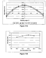
- the retardation profiles of the polymer films are shown in Figure 4A , the biaxiality index versus cure temperature in Figure 4B .
- Polymer films are prepared from a polymerisable mixture as described in example 6, but wherein compound (D1) is replaced by compound (D3) in the same amount (clearing point of the mixture is 90.0°C).
- the retardation at different viewing angles and the biaxiality index BI of the polymer films are shown in table 5.
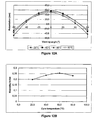
- the retardation profiles of the polymer films are shown in Figure 5A , the biaxiality index versus cure temperature in Figure 5B .
- Polymer films are prepared from a polymerisable mixture as described in example 6, but wherein compound (D1) was replaced by compound (D4) in the same amount (clearing point of the mixture is 86.0°C).
- the retardation at different viewing angles and the biaxiality index BI of the polymer films are shown in table 6.
- the retardation profiles of the polymer films are shown in Figure 6A , the biaxiality index versus cure temperature in Figure 6B .
- Polymer films are prepared from a polymerisable mixture as described in example 6, but wherein compound (D1) was replaced by compound (D5) in the same amount (clearing point of the mixture is 80.0°C).
- the retardation at different viewing angles and the biaxiality index Bl of the polymer films are shown in table 7.
- the retardation profiles of the polymer films are shown in Figure 7A , the biaxiality index versus cure temperature in Figure 7B .
- Polymer films are prepared from a polymerisable mixture as described in example 6, but wherein compound (D1) is replaced by compound (D6) in the same amount (clearing point of the mixture is 84.0°C).
- the retardation at different viewing angles and the biaxiality index BI of the polymer films are shown in table 8.
- the retardation profiles of the polymer films are shown in Figure 8A , the biaxiality index versus cure temperature in Figure 8B .
- Polymer films are prepared from a polymerisable mixture as described in example 6, but wherein compound (D1) is replaced by compound (D7) in the same amount (clearing point of the mixture is 76.0°C).
- the retardation at different viewing angles and the biaxiality index BI of the polymer films are shown in table 9.
- the retardation profiles of the polymer films are shown in Figure 9A , the biaxiality index versus cure temperature in Figure 9B .
- Polymer films are prepared from a polymerisable mixture as described in example 6, but wherein compound (D1) is replaced by compound (D8) in the same amount (clearing point of the mixture is 73.0°C).
- the retardation at different viewing angles and the biaxiality index BI of the polymer films are shown in table 10.
- the retardation profiles of the polymer films are shown in Figure 10A , the biaxiality index versus cure temperature in Figure 10B .
- Polymer films are prepared from a polymerisable mixture as described in example 6, but wherein compound (E2) is replaced by compound (E3) in the same amount (clearing point of the mixture is 92.4°C).
- the retardation at different viewing angles and the biaxiality index Bl of the polymer films are shown in table 11.
- the retardation profiles of the polymer films are shown in Figure 11A , the biaxiality index versus cure temperature in Figure 11B .
- Polymer films are prepared from a polymerisable mixture as described in example 6, but wherein compound (D1) is replaced by compound (D2) and compound (E2) is replaced by compound (E3) in the same amount (clearing point of the mixture is 100.2°C).
- the retardation at different viewing angles and the biaxiality index BI of the polymer films are shown in table 12.
- the retardation profiles of the polymer films are shown in Figure 12A , the biaxiality index versus cure temperature in Figure 12B .
- the mixture has a cholesteric phase and a clearing point of 101.0°C.
- Polymer films are prepared from this polymerisable mixture as described in example 6.
- the retardation at different viewing angles and the biaxiality index BI of the polymer films are shown in table 15.
- the retardation profiles of the polymer films are shown in Figure 13A , the biaxiality index versus cure temperature in Figure 13B .
- Polymer films are prepared from a polymerisable mixture as described in example 16, but wherein compound (D1) is replaced by compound (D2) in the same amount (clearing point of the mixture is 105.0°C).
- the retardation at different viewing angles and the biaxiality index BI of the polymer films are shown in table 14.
- the retardation profiles of the polymer films are shown in Figure 14A , the biaxiality index versus cure temperature in Figure 14B .
- Polymer films are prepared from a polymerisable mixture as described in example 16, but wherein compound (C3) is replaced by compound (C4) in the same amount (clearing point of the mixture is 102.0°C).
- the retardation at different viewing angles and the biaxiality index BI of the polymer films are shown in table 15.
- the retardation profiles of the polymer films are shown in Figure 15A , the biaxiality index versus cure temperature in Figure 15B .
- a polymer film is prepared from this mixture as described in example 1 (annealing temperature 61 °C, cured at room temperature).
- Chiral compound (C5) is disclosed in US 6,511,719 .
- a polymer film is prepared from this mixture as described in example 1 (annealing temperature 43°C).
- a polymer film is prepared from this mixture as described in example 1 (annealing temperature 57°C).
- the following polymerisable cholesteric LC mixture is prepared Compound (A2) 19.60 % Compound (B1) 19.20 % Compound (a) 11.20 % Compound (b) 33.62 % Compound (C2) 2.00 % Paliocolor LC756 ® 9.80 % Compound (E1) 4.00 % FC171® 0.50 % Irganox 1076 ® 0.08 %
- a polymer film is prepared from this mixture as described in example 1 (annealing temperature 58°C).
- Polymer films are prepared from a polymerisable mixture as described in example 23, but wherein compound (A2) is replaced by compound (A3) (example 24), (A4) (example 25) and (A5) (example 26), respectively, in the same amount.
- Table 20 The retardation at different viewing angles and the biaxiality index BI of the polymer films are shown in table 20.
- a polymer film is prepared from this mixture as described in example 1 (annealing temperature 45°C).
- Table 21 The retardation at different viewing angles and the biaxiality index BI of the polymer film are shown in table 21.
- a polymer film is prepared from a polymerisable mixture as described in example 27, but wherein compound (A1) is replaced by compound (A5) in the same amount.
- Table 22 The retardation at different viewing angles and the biaxiality index BI of the polymer film is shown in table 22.
- the following polymerisable cholesteric LC mixture is prepared Compound (A1) 20.00 % Compound (B1) 52.00 % Compound (B2) 13.50 % Paliocolor LC756 ® 10.00 % Compound (E1) 4.00 % FC171® 0.50 %
- a polymer film is prepared from this mixture as described in example 1 (annealing temperature 100°C).
- Table 23 The retardation at different viewing angles and the biaxiality index BI of the polymer film are shown in table 23.
- Polymer films are prepared from a polymerisable mixture as described in example 29, but wherein compound (A1) is replaced by the following compounds in the same amount:
- Example 30 31 32 33 34 35
- Compound A3 A6 A4 A5 A7 A8 annealing temperature 100°C 85°C 70°C 100°C 100°C 100°C 100°C
- Table 24 The retardation at different viewing angles and the biaxiality index BI of the polymer films are shown in table 24.
- the following polymerisable cholesteric LC mixture is prepared Compound (A3) 19.60 % Compound (B1) 45.42 % Compound (a) 5.00 % Compound (b) 13.60 % Compound (C2) 13.50 % Paliocolor LC756 ® 10.00 % Compound (E1) 4.00 % FC171® 0.50 % Irganox 1076 0.08%
- a polymer film is prepared from this mixture as described in example 1 (annealing temperature 77°C).
- Table 25 The retardation at different viewing angles and the biaxiality index BI of the polymer film are shown in table 25.
Abstract
Description
- The invention relates to a polymerisable liquid crystal (LC) material, to optically biaxial films prepared thereof, to novel polymerisable compounds used therein and to the use of the material and films in optical devices like compensators and LC displays (LCDs).
- Biaxial negative C-plate retarders are suitable for use as compensators in LCDs to improve the optical parameters such as contrast ratio and grey scale representation at large viewing angles. A biaxial negative C-plate retarder in its optical properties approximates to a combination of a planar A-plate and a negative C-plate, but shows better optical performance than such a combination. The in-plane anisotropy of the biaxial negative C-plate retarder (Δnxy) approximates to the A-plate and the out-of-plane anisotropy (Δnxz and Δnyz) to the negative C-plate. Simulations have shown that the optical performance of the biaxial negative C-plate retarder is superior to that of the A-plate and negative C-plate stacked sequentially, and shows exceptionally good viewing-angle performance for LCDs. Furthermore, the use of a single biaxial film instead of two stacked films reduces costs and manufacturing problems.
-
WO 03/054111 - However, the films disclosed in prior art do only have a limited biaxiality. To increase the biaxiality of the films new materials and methods are required.
- It was an aim of the present invention to provide new materials and methods for preparing biaxial negative C-plate retarders with improved properties, in particular with a higher biaxiality index. Another aim of the present invention was to extend the pool of materials for preparing biaxial films available to the expert. Other aims of the present invention are immediately evident to the person skilled in the art from the following detailed description.
- It was found that these aims can be achieved by providing materials and methods as claimed in the present invention.
-
US 6,514,578 B1 ,GB 2 388 599 AEP 1 388 538 A1US 6,491,990 B1 ,WO 02/094805 A1 WO 93/22397 A1 - The term 'film' includes rigid or flexible, self-supporting or freestanding films with mechanical stability, as well as coatings or layers on a supporting substrate or between two substrates.
- The term 'liquid crystal or mesogenic material' or 'liquid crystal or mesogenic compound' means materials or compounds comprising one or more rod-shaped, board-shaped or disk-shaped mesogenic groups, i.e. groups with the ability to induce liquid crystal (LC) phase behaviour. LC compounds with rod-shaped or board-shaped groups are also known in the art as 'calamitic' liquid crystals. LC compounds with a disk-shaped group are also known in the art as 'discotic' liquid crystals. The compounds or materials comprising mesogenic groups do not necessarily have to exhibit an LC phase themselves. It is also possible that they show LC phase behaviour only in mixtures with other compounds, or when the mesogenic compounds or materials, or the mixtures thereof, are polymerised.
- For the sake of simplicity, the term 'liquid crystal material' is used hereinafter for both mesogenic and LC materials.
- Polymerisable compounds with one polymerisable group are also referred to as 'monoreactive' compounds, compounds with two polymerisable groups as 'direactive' compounds, and compounds with more than two polymerisable groups as 'multireactive' compounds. Compounds without a polymerisable group are also referred to as 'non-reactive' compounds.
- The term 'reactive mesogen' (RM) means a polymerisable mesogenic or liquid crystal compound.
- The term 'director' is known in the art and means the preferred orientation direction of the long molecular axes (in case of calamitic compounds) or short molecular axis (in case of discotic compounds) of the mesogenic groups in an LC material.
- In films comprising uniaxially positive birefringent LC material the optical axis is given by the director.
- The degree of biaxiality in an optical film or layer can be expressed by the biaxiality index BI = R0/Rth, wherein


wherein d is the film thickness, nx and ny are the principal refractive indices in orthogonal directions within the film plane and nz is the principal refactive index in a direction perpendicular to the film plane. - The invention relates to a polymerisable LC material comprising
- A) at least one polymerisable mesogenic compound having high birefringence of 0.15 or higher, preferably 0.20 or higher and preferably selected of formula I

- P
- is a polymerisable group,
- Sp
- is a spacer group or a single bond,
- A
- is in case of multiple occurrence independently of one another an aromatic or aliphatic 5- or 6-ring, or a group comprising two or three fused aromatic or aliphatic 5- or 6-rings, these rings optionally containing one or more hetero atoms selected from N, O and S, and optionally being substituted by one or more identical or different groups L1,
- Z
- is in case of multiple occurrence independently of one another -O-, -S-, -CO-, -COO-, -OCO-, -S-CO-, -CO-S-, -O-CO-O-, -CO-NR0-, -NR0-CO-, -OCH2-, -CH2O-, -SCH2-, -CH2S-, -CF2O-, -OCF2-, -CF2S-, -SCF2-,-CH2CH2-, -CF2CH2-, -CH2CF2-, -CF2CF2-, -CH=CR0-,-CH=CH-, -CH=CF-, -CY1=CY1-, -C≡C-, -CH=CH-COO-, -OCO-CH=CH- or a single bond,
- R0 and R00
- are independently of each other H or alkyl with 1 to 12 C-atoms,
- Y1 and Y2
- are independently of each other H, F, Cl or CN,
- m1, m2
- are independently of each other 0, 1 or 2, with m1 +m2 ≤ 3,
- L1, L2
- are independently of each other F, Cl, Br, I, CN, NO2, P-Sp- or alkyl, alkoxy, alkylcarbonyl, alkoxycarbonyl, alkylcarbonlyoxy or alkoxycarbonyloxy with 1 to 12 C atoms, wherein one or more H atoms are optionally replaced by F or Cl,
- r1, r2
- are independently of each other 0, 1, 2, 3 or 4,
- R1
- is H, halogen, CN, NCS, SF5, P-Sp- or straight chain or branched alkyl with 1 to 20 C-atoms that is optionally mono- or polysubstituted by F, Cl, Br, I or CN, and wherein one or more non-adjacent CH2-groups are optionally replaced, in each case independently from one another, by -O-, -S-, -NR0-,-SiR0R00-, -CO-, -COO-, -OCO-, -OCO-O-, -NR0-CO-,-CO-NR0-, -NR0-CO-NR0-, -S-CO-, -CO-S-, -CY1=CY2-or -C≡C- in such a manner that O and/or S atoms are not linked directly to one another,
- B) at least one polymerisable mesogenic compound having two or more polymerisable groups,
- C) at least one chiral compound, preferably having a high helical twisting power (HTP) of at least 40µm-1, very preferably at least 60µm-1,
- D)optionally at least one monoreactive polymerisable compound having a liquid crystal phase, preferably an enantiotropic nematic phase, and a high clearing point, preferably of 75°C or higher,
- E) at least one dichroic photoinitiator,
characterized in that it comprises at least one compound of formula I selected of formula la
- P
- is a polymerisable or reactive group,
- Sp
- is a spacer group or a single bond,
- Z0
- is -COO-, -OCO- or a single bond,
- L1a,1b,2a,2b
- are independently of each other F, Cl, CN, (O)aCbFcH2b+1-c or COCH3,
- r1 a, r1 b, r2a, r2b
- are independently of each other 0 or 1, with at least one of r1 a, r1 b, r2a, r2b being 1,
- R1a
- is Cl or optionally mono- or polyfluorinated straight-chain or branched alkyl with 1 to 6 C-atoms wherein one or two non-adjacent CH2-groups are optionally replaced by -O-, -S-, -CO-, -COO-, -OCO-, -OCO-O-, -S-CO- or -CO-S- in such a manner that O and/or S atoms are not linked directly to one another,
- a
- is 0 or 1,
- b
- is 1 or 2,
- c
- is 0, 1, 2, 3, 4 or 5.
- The invention further relates to an optically biaxial film obtainable from a polymerisable LC material as described above and below.
- The invention further relates to the use of a biaxial film as described above and below as retardation or compensation film in optical devices like for example LCDs.
- The invention further relates to a compensator comprising a biaxial film as described above and below.
- The invention further relates to an LCD comprising a compensator or biaxial film as described above and below.
-
-
Figure 1 shows the retardation profile (retardation vs. viewing angle) of biaxial films according to examples 1, 2 and 3 of the present invention. -
Figure 2 shows the retardation profile of biaxial films according to examples 4 and 5 of the present invention. -
Figures 3A-15A show the retardation profile of biaxial films according to examples 6-18 of the present invention. -
Figures 3B-15B show the biaxiality index vs. curing temperature of biaxial films according to examples 6-18 of the present invention. - Especially preferred compounds of formula I are those wherein
- m1 is 1,
- m2 is 0,
- R1 is selected from Cl or optionally mono- or polyfluorinated straight-chain or branched alkyl with 1 to 12 C-atoms, preferably 1 to 6 C-atoms wherein one or two non-adjacent CH2-groups are optionally replaced by -O-, -S-, -CO-, -COO-, -OCO-, -OCO-O-, -S-CO- or -CO-S- in such a manner that O and/or S atoms are not linked directly to one another, very preferably optionally mono- or polyfluorinated straight-chain or branched alkyl Cl, alkyl, alkoxy or alkylsulfanyl (-S-alkyl) with 1 to 6 C-atoms,
- A is 1,4-cyclohexylene or 1,4-phenylene that is optionally substituted with 1 to 4 groups L1,
- r1 is 0, 1 or 2,
- r2 is 0, 1 or 2,
- r1+r2 is 1 or 2,
- Z is -COO-, -OCO- or a single bond.
- At least one compound of formula Ia is used

Z0 is -COO-, -OCO- or a single bond, preferably -COO-,
L1a,1b,2a,2b are independently of each other F, Cl, CN, (O)aCbFcH2b+1-c or COCH3, preferably Cl, CH3 or OCH3,
r1 a, r1 b, r2a, r2b are independently of each other 0 or 1, with at least one of r1 a, r1b, r2a, r2b being 1,
R1a is Cl or optionally mono- or polyfluorinated straight-chain or branched alkyl with 1 to 6 C-atoms wherein one or two non-adjacent CH2-groups are optionally replaced by -O-, -S-, -CO-, - COO-, -OCO-, -OCO-O-, -S-CO- or -CO-S- in such a manner that O and/or S atoms are not linked directly to one another,
a is 0 or 1,
b is 1 or 2,
c is 0, 1, 2, 3, 4 or 5. - Especially preferred are compounds of formula la wherein
- r1 a and r1 b are1,
- r1 b is 0,
- r2b is 0,
- r2a and r2b are 0,
- r1a is 1 and r1b is 0,
- r2a is 1 and r2b is 0,
- R1a is Cl or optionally mono- or polyfluorinated alkyl, alkoxy or alkylsulfanyl (-S-alkyl) with 1 to 6 C-atoms, very preferably Cl, CH3, C2H5, OCH3, OC2H5, SCH3, SC2H5, OCF3, OCHF2, OCH2F or OC2F5, most preferably Cl, CH3, C2H5, OCH3 or SCH3.
- The compounds of formula la are novel and are another aspect of the invention.
- A further aspect of the invention relates to the use of novel compounds of formula la in optical and electrooptical components or devices, in particular optical films, polarisers, compensators, beam splitters, reflective films, alignment layers, colour filters, holographic elements, hot stamping foils, coloured images, decorative or security markings, liquid crystal pigments, adhesives, synthetic resins with anisotropic mechanical properties, cosmetics, diagnostics, nonlinear optics, optical information storage or in LC media for LC display devices, preferably for use in polymerisable LC materials and for the preparation of optically biaxial films.
- The novel compounds of formula la can be prepared in analogy to the methods described in
US 6,514,578 orGB 2 388 599 Aschemes 


- Especially preferred are compounds of formula II wherein Z1 and Z2 are -CH2CH2-, -COO-, -OCO- or a single bond, in particular wherein Z1 is -COO- and Z2 is -OCO-. Further preferred are compounds of formula II wherein r2 and r3 are 0, r1 is 0, 1 or 2 and L1 is F, Cl, CH3, C2H5, OCH3 or COCH3.
- The chiral compounds of component C) can be selected from, optionally polymerisable, chiral dopants which are known from prior art, like for example the commercially available R- or S-811, R- or S-1011, R- or S-2011, R- or S-3011, R- or S-4011, R- or S-5011, or CB 15 (from Merck KGaA, Darmstadt, Germany).
- Especially preferred are chiral compounds having a high value of the helical twisting power (HTP), in particular with a HTP of at least 40µm-1, very preferably of at least 60µm-1, for example from 60 to 110µm-1.
- Very preferred are chiral compounds with a high HTP as disclosed in
WO 98/00428 GB 2,328,207 WO 02/94805 WO 02/34739 WO 02/06265 WO 02/06196 WO 02/06195 - Especially preferred are chiral binaphthols as disclosed in
WO 02/34739 WO 02/94805 
- Very preferred are compounds of formula III wherein R3 is P-Sp. Further preferred are compounds of formula III wherein m3 is 0 or 1, Z is -COO-, -OCO- or a single bond, A is 1,4-phenylene optionally substituted by 1 or 2 groups L1 or trans-1,4-cyclohexylene. Very preferred are the following compounds

- Component D) preferably comprises one or more compounds having a nematic phase, preferably an enantiotropic nematic phase, and a clearing point (nematic-isotropic phase transition temperature) of 85°C or higher, preferably 100°C or higher. Very preferred are compounds selected of formula IV

- m4
- is 0, 1 or 2,
- Z3
- is -COO-, -OCO- or a single bond,
- L4, L5
- have independently of each other one of the meanings of L1 in formula I,
- r4, r5
- are independently of each other 0, 1, 2, 3 or 4, with r4+r5 > 0,
- R2
- is H, halogen, CN, NCS, SF5 or straight chain or branched alkyl with 1 to 20 C-atoms that is optionally mono- or polysubstituted by F, Cl, Br, I or CN, and wherein one or more non-adjacent CH2 groups are optionally replaced, in each case independently from one another, by -O-, -S-, -NR0-, -SiR0R00-, -CO-,-COO-, -OCO-, -OCO-O-, -NR0-CO-, -CO-NR0-, -NR0-CO-NR0-, -S-CO-, -CO-S-, -CY1=CY2- or -C≡C- in such a manner that O and/or S atoms are not linked directly to one another.
- Especially preferred are compounds of formula IV wherein m4 is 0 or 1, most preferably 0, Z3 is -COO-, r1 is 0, r4 is 1 and r5 is 0 or 1. Very preferred are compounds of the following formula

- L4a,5a
- are independently of each other F, Cl, CH3, C2H5, OCH3 or COCH3,
- r4a, r5a
- are 0 or 1, with r4a + r5a > 0,
- R2a
- is Cl or optionally mono- or polyfluorinated straight-chain alkyl with 1 to 12 C-atoms, preferably 1 to 6 C-atoms
wherein one or two non-adjacent CH2-groups are optionally replaced by -O-, -S-, -CO-, -COO-, -OCO-, -OCO-O-, -S-CO- or -CO-S- in such a manner that O and/or S atoms are not linked directly to one another. - Especially preferred are compounds of formula IVa wherein
- r4a is 1,
- r5a is 0,
- L4a or L5a is Cl or OCH3,
- R2a is Cl, CN, OCH3, OC2H5, SCH3, SC2H5, OCF3, OCHF2, OCH2F or OC2F5, very preferably Cl or OCH3.
- Component E) preferably comprises a mesogenic or liquid crystal photoinitiator.
- As dichroic photoinitiator for example the following compounds can be used

- Especially preferred are dichroic photoinitiators comprising an α-amino group as disclosed in
EP-A-1 388 538 , in particular those of formula V
- Very preferred compounds of formula V are the following


- In the formulae shown above and below, R, R1 and R2 can be a polar or an unpolar group. Polar groups are preferably selected from halogen, CN, NCS, SF5, OCH3, optionally mono- or polyfluorinated alkycarbonyl, alkoxycarbonyl, alkylcarbonyloxy or alkoxycarbonyloxy with 1 to 4 C-atoms, and mono-, oligo- or polyfluorinated alkyl or alkoxy with 1 to 4 C-atoms. Unpolar groups are preferably selected from optionally halogenated alkyl, alkoxy, alkycarbonyl, alkoxycarbonyl, alkylcarbonyloxy or alkoxycarbonyloxy with 1 or more, preferably 1 to 15 C-atoms which is not covered by the above definition of 'polar group'.
- Especially preferred polar groups are selected of F, Cl, CN, OCH3, COCH3, COC2H5, COOCH3, COOC2H5, CF3, CHF2, CH2F, OCF3, OCHF2, OCH2F, C2F5 and OC2F5, in particular F, Cl, CN, CF3, OCHF2 and OCF3. Especially preferred unpolar groups are selected from unsubstituted alkyl with 1 to 12 C-atoms or unsubstituted alkoxy with 2 to 12 C-atoms.
- If R, R1 or R2 is an alkyl or alkoxy group, i.e. where the terminal CH2 group is replaced by -O-, this may be straight-chain or branched. It is preferably straight-chain, has 1, 2, 3, 4, 5, 6, 7 or 8 carbon atoms and accordingly is preferably methyl, ethyl, propyl, butyl, pentyl, hexyl, heptyl, octyl, methoxy, ethoxy, propoxy, butoxy, pentoxy, hexoxy, heptoxy, or octoxy, furthermore nonyl, decyl, undecyl, dodecyl, tridecyl, tetradecyl, pentadecyl, nonoxy, decoxy, undecoxy, dodecoxy, tridecoxy or tetradecoxy, for example.
- If R, R1 or R2 is oxaalkyl, i.e. where one CH2 group is replaced by -O-, it is preferably straight-chain 2-oxapropyl (=methoxymethyl), 2-(=ethoxymethyl) or 3-oxabutyl (=2-methoxyethyl), 2-, 3-, or 4-oxapentyl, 2-, 3-, 4-, or 5-oxahexyl, 2-, 3-, 4-, 5-, or 6-oxaheptyl, 2-, 3-, 4-, 5-, 6- or 7-oxaoctyl, 2-, 3-, 4-, 5-, 6-, 7- or 8-oxanonyl or 2-, 3-, 4-, 5-, 6-,7-, 8- or 9-oxadecyl, for example.
- If R, R1 or R2 is alkylsulfanyl (thioether), i.e. alkyl where the CH2 group that is linked to the adjacent group is replaced by -S-, it is preferably straight-chain, has 1, 2, 3, 4, 5, 6, 7 or 8 carbon atoms and accordingly is preferably methylsulfanyl, ethylsulfanyl, propylsulfanyl, butylsulfanyl, pentylsulfanyl, hexylsulfanyl, heptylsulfanyl, octylsulfanyl, furthermore nonylsulfanyl, decylsulfanyl, undecylsulfanyl or dodecylsulfanyl, for example.
- R, R1 or R2 can be an achiral or a chiral group.
- In the formulae shown above and below, A is preferably selected from 1,4-cyclohexylene, 1,4-phenylene, tetrahydropyrane-2,5-diyl, dioxane-2,5-diyl, furane-2,5-diyl, thiophene-2,5-diyl, pyrrol-2,5-diyl, pyridine-2,5-diyl, pyrimidine-2,5-diyl, naphthalene-2,6-diyl, 1,2,3,4-tetrahydronaphthalene-2,6-diyl, decaline-2,6-diyl, indane-2,5-diyl, these groups optionally being mono- or polysubstituted by L1 as defined above.
- Z, Z0 and Z1-3 are preferably selected from -COO-, -OCO-, -CH2CH2-, -OCF2-, -CF2O-, -CY1=CY2- or a single bond, very preferably -COO-, -OCO- or a single bond.
- L1-5 are preferably selected from F, Cl, CN, NO2 CH3, C2H5, OCH3, OC2H5, COCH3, COC2H5, COOCH3, COOC2H5, CF3, OCF3, OCHF2 or OC2F5, in particular F, Cl, CN, CH3, C2H5, OCH3, COCH3 or OCF3, most preferably F, Cl, CH3, OCH3 or COCH3.
- Preferably -(A-Z)m1-, -(A-Z)m2-, -(A-Z)m3- and -(A-Z)m4-, are selected from the groups listed below and their mirror images. Therein, Phe is 1,4-phenylene, PheL is 1,4-phenylene that is substituted by 1 to 4 groups L1 as defined above, Cyc is 1,4-cyclohexylene and Z has one of the meanings of Z1 in formula I.
- -Phe-Z- M1
- -Cyc-Z- M2
- -PheL-Z- M3
- -Cyc-Z-Cyc-Z- M4
- -Phe-Z-Cyc-Z- M5
- -PheL-Z-Cyc-Z- M6
- -Phe-Z-Phe-Z- M7
- -PheL-Z-Phe-Z- M8
- -PheL-Z-PheL-Z- M9
- PheL in these preferred formulae is preferably denoting

- Halogen is preferably F or Cl.
- Y1 and Y2 are preferably H or F.
- The polymerisable group P is a group that is capable of participating in a polymerisation reaction, like radicalic or ionic chain polymerisation, polyaddition or polycondensation, or capable of being grafted, for example by condensation or addition, to a polymer backbone in a polymeranaloguous reaction. Especially preferred are polymerisable groups for chain polymerisation reactions, like radicalic, cationic or anionic polymerisation. Very preferred are polymerisable groups comprising a C-C double or triple bond, and polymerisable groups capable of polymerisation by a ring-opening reaction, like oxetanes or epoxides.
- Very preferably the polymerisable group P is selected from
CH2=CW1-COO-, CH2=CW1-CO-,

- Especially preferred groups P are CH2=CH-COO-, CH2=C(CH3)-COO-, CH2=CH-, CH2=CH-O-, (CH2=CH)2CH-OCO-, (CH2=CH)2CH-0-,

- Very preferred are acrylate and oxetane groups. Oxetanes produce less shrinkage upon polymerisation (cross-linking), which results in less stress development within films, leading to higher retention of ordering and fewer defects. Oxetane cross-linking also requires a cationic initiator, which unlike free radical initiator is inert to oxygen.
- As for the spacer group Sp all groups can be used that are known for this purpose to the skilled in the art. The spacer group Sp is preferably of formula Sp'-X, such that P-Sp- is P-Sp'-X-, wherein
- Sp'
- is alkylene with 1 to 20 C atoms, preferably 1 to 12 C-atoms, which is optionally mono- or polysubstituted by F, Cl, Br, I or CN, and wherein one or more non-adjacent CH2 groups are optionally replaced, in each case independently from one another, by -O-, -S-, -NH-, -NR0-, -SiR0R00-, -CO-, -COO-,-OCO-, -OCO-O-, -S-CO-, -CO-S-, -NR0-CO-O-, -O-CO-NR0-,-NR0-CO-NR0-, -CH=CH- or -C≡C- in such a manner that O and/or S atoms are not linked directly to one another,
- X
- is -O-, -S-, -CO-, -COO-, -OCO-, -O-COO-, -CO-NR0-, -NR0-CO-, -NR0-CO-NR0-, -OCH2-, -CH2O-, -SCH2-, -CH2S-, -CF2O-,-OCF2-, -CF2S-, -SCF2-, -CF2CH2-, -CH2CF2-, -CF2CF2-, -CH=N-, -N=CH-, -N=N-, -CH=CR0-, -CY1=CY2-, -C≡C-, -CH=CH-COO-,-OCO-CH=CH- or a single bond,
- R0 and R00
- are independently of each other H or alkyl with 1 to 12 C-atoms, and
- Y1 and Y2
- are independently of each other H, F, Cl or CN.
- X is preferably -O-, -S-, -OCH2-, -CH2O-, -SCH2-, -CH2S-, -CF2O-,-OCF2-, -CF2S-, -SCF2-, -CH2CH2-, -CF2CH2-, -CH2CF2-, -CF2CF2-,-CH=N-, -N=CH-, -N=N-, -CH=CR0-, -CY1=CY2-, -C≡C- or a single bond, in particular -O-, -S-, -C≡C-, -CY1=CY2- or a single bond, very preferably a group that is able to from a conjugated system, such as -C≡C- or -CY1=CY2-, or a single bond.
- Typical groups Sp' are, for example, -(CH2)p-, -(CH2CH2O)q-CH2CH2-,-CH2CH2-S-CH2CH2- or -CH2CH2-NH-CH2CH2- or -(SiR0R00-O)p-, with p being an integer from 2 to 12, q being an integer from 1 to 3 and R0 and R00 having the meanings given above.
- Preferred groups Sp' are ethylene, propylene, butylene, pentylene, hexylene, heptylene, octylene, nonylene, decylene, undecylene, dodecylene, octadecylene, ethyleneoxyethylene, methyleneoxybutylene, ethylene-thioethylene, ethylene-N-methyliminoethylene, 1-methylalkylene, ethenylene, propenylene and butenylene for example.
- Further preferred are compounds with one or two groups P-Sp-
wherein Sp is a single bond. In case of compounds with two groups P-Sp, each of the two polymerisable groups P and the two spacer groups Sp can be identical or different. - In another preferred embodiment the group Sp' is a chiral group of the following formula

- Q1
- is an alkylene or alkylene-oxy group with 1 to 9 C atoms or a single bond,
- Q2
- is an alkyl or alkoxy group with 1 to 10 C atoms which may be unsubstituted, mono- or polysubstituted by F, Cl, Br or CN, it being also possible for one or more non-adjacent CH2 groups to be replaced, in each case independently from one another, by -C≡C-, -O-, -S-, -NH-, -N(CH3)-, -CO-, -COO-, -OCO-, -OCO-O-, -S-CO- or -CO-S- in such a manner that oxygen atoms are not linked directly to one another,
- Q4
- is an alkylene or alkylene-oxy group with 1 to 10 C atoms or a single bond, being different from Q1,
- The polymerisable LC material according to the present invention preferably has a chiral smectic or chiral nematic (cholesteric) LC phase or a blue phase. Especially preferred is a cholesteric LC (CLC) material.
- The polymerisable LC material preferably comprises one or more monofunctional chiral polymerisable mesogenic compounds and one or more di- or multifunctional achiral polymerisable mesogenic compounds.
- Further to the compounds of component A-E) mentioned above, the polymerisable LC material may comprise one or more additional polymerisable mesogenic compounds. These additional compounds are preferably selected of the following formulae


- The compounds of formula I, IV, II, III and V and R1-R10 are known from prior art or can be synthesized according to or in analogy to methods which are known per se and which are described in standard works of organic chemistry such as, for example, Houben-Weyl, Methoden der organischen Chemie, Thieme-Verlag, Stuttgart.
- Compounds of formula I are disclosed for example in
US 6,514,578 . Compounds of formula IV are disclosed inUS 6,491,990 . Compounds of formula III are disclosed inWO 02/94805 EP-A-1 388 538 . Compounds of formula II and suitable additional polymerisable mesogenic compounds like those of formula R1-R10 are disclosed for example inWO 93/22397 US 5,518,652 ,DE 195 04 224 ,US 5,750,051 ,US 5,770,107 andUS 6,514,578 . - Further to components A)-E) the polymerisable LC material preferably comprises one or more components selected from
- F) one or more surfactants,
- G) one or more non-mesogenic compounds having one, two or more polymerisable groups,
- H) one or more chain transfer agents,
- I) one or more dyes having an absorption maximum at a wavelength used to initiate photopolymerisation of the material.
- In a preferred embodiment the polymerisable material comprises one or more surfactants F) to achieve planar alignment with a low tilt angle. Suitable surfactants are described for example in J. Cognard, Mol.Cryst.Liq.Cryst. 78, ). Particularly preferred are non-ionic surfactants, e.g. non-ionic fluorocarbon surfactants, like the commercially available Fluorad® (from 3M), or Zonyl FSN® (from DuPont), or polymerizable fluorocarbon surfactants as disclosed in
EP 1 256 617 A1GB 2 383 040 A - In another preferred embodiment the polymerisable material comprises one or more non-mesogenic polymerisable compounds G), preferably in a concentration from 0 to 30%, preferably 0 to 20 %. Typical examples of monoreactive non-mesogenic compounds are alkylacrylates or alkylmethacrylates. Typical examples for direactive non-mesogenic compounds are alkyldiacrylates or alkyldimethacrylates with alkyl groups of 1 to 20 C atoms. Typical examples for multireactive non-mesogenic compounds are trimethylpropanetrimethacrylate or pentaerythritoltetraacrylate.
- In another preferred embodiment the polymerisable material comprises one or more chain transfer agents H), in order to modify the physical properties of the polymer film. Especially preferred are thiol compounds, such as monofunctional thiol compounds like e.g. dodecane thiol or multifunctional thiol compounds like e.g. trimethylpropane tri(3-mercaptopropionate), very preferably mesogenic or LC thiol compounds as for example disclosed in
WO 96/12209 WO 96/25470 US 6,420,001 . When adding a chain transfer agent, the length of the free polymer chains and/or the length of the polymer chains between two crosslinks in the polymer film can be controlled. When the amount of the chain transfer agent is increased, the polymer chain length in the polymer film is decreasing. - In another preferred embodiment the polymerisable material comprises one or more dyes I) having an absorption maximum at the wavelength of the radiation used for polymerisation of the material. Especially preferred are UV dyes like e.g. 4,4'-azoxy anisole or the commercially available Tinuvin (from Ciba AG, Basel, Switzerland).
- A preferred polymerisable LC mixture comprises
- A) 5 to 60 %, preferably 10 to 40 %, very preferably 15 to 30 % of one or more compounds of formula I,
- B) 5 to 80 %, preferably 10 to 65 %, very preferably 15 to 55 % of one or more mesogenic compounds having two or more polymerisable groups,
- C) 0.1 to 20 %, preferably 1 to 15 %, very preferably 2 to 10 % of one or more chiral compounds,
- D) 0 to 70 %, preferably 5 to 60 %, very preferably 10 to 50 % of one or more compounds of formula IV,
- E) 0.1 to 15 %, preferably 0.5 to 10 %, very preferably 1 to 7 % of one or more dichroic photoinitiators,
- F) 0 to 10 %, preferably 0.01 to 5 %, very preferably 0.05 to 3 % of one or more surfactants,
- G) 0 to 30 %, preferably 5 to 20 % of one or more mono-, di- or multifunctional polymerisable non-mesogenic compounds,
- H) 0 to 15 %, preferably 0.5 to 7 % of one or more chain transfer agents,
- I) 0 to 10 %, preferably 0.1 to 7 % of one or more dyes having an absorption maximum at the wavelength used for polymerisation of the material.
- The polymerisable LC material according to the present invention can be used for the preparation of biaxial films. Thus, another aspect of the invention relates to a biaxial film which is obtainable from the polymerisable material as described above and below.
- The biaxial film according to the present invention preferably has a cholesteric structure with a distorted helix, resulting in an elliptical, discotic refractive index ellipsoid. Furthermore, the pitch of the cholesteric helix has a value well below the visible wavelength range, preferably below 225 nm, so that only the average directional refractive indices are experienced. As a consequence the Bragg reflection bands occur in the UV range of light, so the film is transparent to visible wavelengths of light and behaves purely as retarders between crossed polarisers for these visible wavelengths.
- The biaxial film has optical biaxial negative C symmetry with nx > ny > nz, wherein nx and ny are the principal refractive indices in orthogonal directions within the film plane and nz is the principal refractive index perpendicular to the film plane.
- The reflection wavelength of the biaxial film is preferably below 380 nm. Further preferred is a biaxial film that is substantially transparent for light with a wavelength of 400 nm or higher, preferably 380 nm or higher. Very preferably the biaxial film is substantially transparent for visible light with a wavelength from 380 to at least 780 nm.
- The thickness of the biaxial film is preferably from 0.5 to 5 µm, very preferably from 0.5 to 3 µm.
- The on-axis retardation (previously defined as R0) of a biaxial film according to the present invention is preferably from 10 to 150 nm, very preferably from 20 to 100 nm, most preferably from 30 to 80 nm.
- Another preferred embodiment relates to a biaxial film with approximately quarter wave (λ/4) retardation (λ = wavelength of incident light) for use as quarter wave retardation film (QWF). Especially preferred for such uses are retardation values from 90 to 200 nm, preferably from 100 to 175 nm.
- Another preferred embodiment relates to a biaxial film with approximately half wave (λ/2) retardation for use as half wave retardation film (HWF). Especially preferred for such uses are retardation values from 180 to 400 nm, preferably from 200 to 350 nm.
- Another aspect of the invention relates to a method of preparing a biaxial film. Especially preferred is a process of preparing a biaxial film by providing a layer of a polymerisable LC material as described above and below on a substrate, aligning the material in its LC phase into planar orientation, photopolymerising the material by exposure to linear polarised light, and optionally removing the polymerised material from the substrate.
- Very preferably the biaxial film is prepared in analogy to the method as described in
WO 03/54111 - The aligned cholesteric material is then exposed to linear polarised UV light. The dichroic photoinitiator (E) present in the material locally aligns with its UV-absorbing axis parallel to the LC director. When illuminated with polarised UV light, polymerisation-initiating free radicals are predominantly produced where the local director lies parallel to the direction of polarisation.
- Inhomogeneous free-radical production results in local polymerisation, predominantly of the highly reactive components, like the di- or multifunctional polymerisable compounds. This results in concentration gradients between the high and low reactive components within a half turn of the helix. The highly reactive components become concentrated where the director lies parallel to the E-field (maximum concentration of free radicals) and the less reactive components, like the monofunctional polymerisable or non-polymerisable compounds, become concentrated where the director is perpendicular to the E-field. Localised variation of the chiral component results in distortion of the sinusoidal helix (which above and below is also referred to as 'distorted' or 'deformed' helix).
- By using the polymerisable LC material according to the present invention it is possible to achieve films with a biaxiality index BI of 0.2 or more. The biaxial films according to the present invention preferably have a value of BI ≥ 0.14, in particular ≥ 0.20, very preferably ≥ 0.25, most preferably ≥ 0.30.
- The polymerisable LC chiral mixture is preferably designed such that its selective reflection wavelength is below the wavelength of light that is normally used for polymerisation (typically UV light of about 365nm) and enables local variation of the birefringence. This is achieved by using chiral compounds of formula III with high twist to push the Bragg reflection band into the UV, and by using improved dichroic photoinitiators, especially those of formula V.
- The polymerisable LC chiral mixture according to the present invention allows to make the film production process suitable for manufacture on a plastic substrate, with a cure time of less than 3 minutes, preferably less than 1 minute, which is especially suitable for mass production.
- The polymerisable LC mixture according to the present invention has a high clearing point and allows polymerisation at higher temperature within the LC phase. It was found that, by increasing the polymerisation temperature to a certain extent within the LC phase of the polymerisable material, it is possible to increase the biaxiality of the resulting polymer film. Therefore, polymerisable LC mixtures with high clearing points are especially suitable and preferred. Preferably the polymerisation temperature is selected, within the LC phase of the polymerisable material, in a range from 40°C to 100°C, in particular from 40°C to 90°C, preferably from 50°C to 80°C, very preferably from 55 to 65°C or from 60 to 80°C.
- It is also possible, by varying the polarisation direction of the linear polarised photoradiation, to control the direction of the slow axis of the biaxial film (the "slow axis" corresponds to the x-direction, i.e. the direction of the highest refractive index nx). For example, irradiation with linear polarised UV light can be achieved by passing UV light through a linear polariser (e.g. a commercially available dye-doped absorption polarizer). The direction of the slow axis in the resulting biaxial film will then correspond to the direction of the transmission axis of the polariser. By rotating the polariser, the direction of the slow axis can thus be controlled.
- In another preferred embodiment of the present invention the optically biaxial film comprises at least two areas with different retardation birefringence or a pattern of two or more areas having different retardation.
- Such a film can be prepared by the method as described above, wherein only selected areas of the polymerisable material are polymerised. This is achieved for example by photopolymerisation through a photomask so that only the uncovered areas are exposed to UV light. Different areas are then polymerised under different conditions, e.g. at different curing temperature, leading to a change in on-axis retardation.
- It is also possible to prepare a biaxial film that comprises a pattern of one or more, preferably one, two or three different regions having different retardation values, each of said values being adjusted such that its efficiency of converting linearly polarised light into circularly polarised light is optimised for light of one of the primary colours red, green and blue (R, G, B). In particular, said values of retardation are as follows:
- For red light of a wavelength of 600 nm the retardation is from 140 to 190 nm, preferably 145 to 180 nm, very preferably 145 to 160 nm, most preferably 150 nm.
For green light of a wavelength of 550 nm the retardation is from 122 to 152 nm, preferably 127 to 147 nm, very preferably 132 to 142 nm, most preferably 137 nm.
For blue light of a wavelength of 450 nm the retardation is from 85 to 120 nm, preferably 90 to 115 nm, very preferably 100 to 115 nm, most preferably 112 nm. - For preparation of the biaxial film, the polymerisable material is preferably coated or printed onto substrate, aligned into a uniform orientation and polymerised to permanently fix the orientation. As a substrate for example a glass or quarz sheet or a plastic film or sheet can be used. It is also possible to put a second substrate on top of the coated mixture prior to and/or during and/or after polymerisation. The substrates can be removed after polymerisation or not. When using two substrates in case of curing by actinic radiation, at least one substrate has to be transmissive for the actinic radiation used for the polymerisation. Isotropic or birefringent substrates can be used. In case the substrate is not removed from the polymerized film after polymerisation, preferably isotropic substrates are used.
- Preferably at least one substrate is a plastic substrate such as for example a film of polyester such as polyethyleneterephthalate (PET) or polyethylenenaphthalate (PEN), of polyvinylalcohol (PVA), polycarbonate (PC) or triacetylcellulose (TAC), especially preferably a PET film or a TAC film. As a birefringent substrate for example an uniaxially stretched plastic film can be used. For example PET films are commercially available from DuPont Teijin Films under the trade name Melinex ®.
- The polymerisable material can be applied onto the substate by conventional coating techniques like spin-coating or blade coating. It can also be applied to the substrate by conventional printing techniques which are known to the expert, like for example screen printing, offset printing, reel-to-reel printing, letter press printing, gravure printing, rotogravure printing, flexographic printing, intaglio printing, pad printing, heat-seal printing, ink-jet printing or printing by means of a stamp or printing plate.
- It is also possible to dissolve the polymerisable material in a suitable solvent. This solution is then coated or printed onto the substrate, for example by spin-coating or printing or other known techniques, and the solvent is evaporated off before polymerization. In most cases it is suitable to heat the mixture in order to facilitate the evaporation of the solvent. As solvents for example standard organic solvents can be used the solvents can be selected for example from ketones like e.g. acetone, methyl ethyl ketone, methyl propyl ketone or cyclohexanone, acetates like e.g. methyl, ethyl or butyl acetate or methyl acetoacetate, alcohols like e.g. methanol, ethanol or isopropyl alcohol, aromatic solvents like e.g. toluene or xylene, halogenated hydrocarbons like e.g. di- or trichloromethane, glycols or their esters like e.g. PGMEA (propyl glycol monomethyl ether acetate), γ-butyrolactone, and the like. It is also possible to use binary, ternary or higher mixtures of the above solvents.
- Polymerisation of the material is preferably achieved by exposing it to heat or actinic radiation. Actinic radiation means irradiation with light, like UV light, IR light or visible light, irradiation with X-rays or gamma rays or irradiation with high energy particles, such as ions or electrons. Preferably polymerisation is carried out by photoirradiation, in particular with UV light, very preferably with linear polarised UV light. As a source for actinic radiation for example a single UV lamp or a set of UV lamps can be used. When using a high lamp power the curing time can be reduced. Another possible source for photoradiation is a laser, like e.g. a UV laser, an IR laser or a visible laser.
- In addition to the dichroic photoinitiator of component E) the polymerisable material may also comprise one or more conventional photoinitators. As standard photoinitiator for radical polymerisation for example the commercially available Irgacure® 651, Irgacure® 184, Darocure® 1173 or Darocure® 4205 (all from Ciba Geigy AG) can be used, whereas in case of cationic photopolymerisation the commercially available UVI 6974 (Union Carbide) can be used.
- The curing time is dependent, inter alia, on the reactivity of the polymerisable material, the thickness of the coated layer, the type of polymerisation initiator and the power of the UV lamp. The curing time according to the invention is preferably not longer than 10 minutes, particularly preferably not longer than 5 minutes and very particularly preferably shorter than 2 minutes. For mass production short curing times of 3 minutes or less, very preferably of 1 minute or less, in particular of 30 seconds or less, are preferred.
- The polymerisable material can additionally comprise one or more other suitable components such as, for example, catalysts, sensitizers, stabilizers, chain-transfer agents, inhibitors, accelerators, co-reacting monomers, surface-active compounds, lubricating agents, wetting agents, dispersing agents, hydrophobing agents, adhesive agents, flow improvers, defoaming agents, deaerators, diluents, reactive diluents, auxiliaries, colourants, dyes or pigments.
- Apart from using surfactants of component F), uniform alignment of the material can be aided for example by shearing the material, e.g. by means of a doctor blade. It is also possible to apply an alignment layer, for example a layer of rubbed polyimide or sputtered SiOx, on top of at least one of the substrates. Alignment can also be achieved by rubbing the substrate without applying an additional alignment layer, e.g. by means of a rubbing cloth or a rubbing roller.
- In a preferred embodiment the polymerisable LC material is annealed at a high temperature within the LC phase before polymerisation to improve the alignment, preferably at a temperature close to its clearing point, very preferably less than 5°C, most preferably less than 2°C below its clearing point.
- In some cases it is of advantage to apply a second substrate to aid alignment and exclude oxygen that may inhibit the polymerisation. In a preferred embodiment polymerisation is carried out under an atmosphere of inert gas like for example nitrogen or argon.
- The biaxial film according to the present invention can be used alone or in combination with other retardation films as compensator or retarder, in particular for viewing angle compensation in LCDs.
- Thus, another aspect of the invention relates to an LCD device comprising at least one biaxial film or compensator as described above and below.
- Preferably the LCD device comprises the following elements
- an LC cell formed by two transparent substrates having surfaces which oppose each other, an electrode layer provided on the inside of at least one of said two transparent substrates and optionally superposed with an alignment layer, and an LC medium which is present between the two transparent substrates,
- a polariser arranged outside said transparent substrates, or a pair of polarisers sandwiching said substrates, and
- at least one biaxial film or compensator according to the present invention, being situated between the LC cell and at least one of said polarisers.
- The above display elements can be be separated, stacked, mounted on top of each other or connected by means of adhesive layers in any combination of these means of assembly.
- The biaxial film and compensator according to the present invention can be used for compensation of conventional displays, in particular those of the TN (twisted nematic), HTN (highly twisted nematic) or STN (super twisted nematic) mode, in AMD-TN (active matrix driven TN) displays, in displays of the IPS (in plane switching) mode, which are also known as 'super TFT' displays, in displays of the DAP (deformation of aligned phases) or VA (vertically aligned) mode, like e.g. ECB (electrically controlled birefringence), CSH (colour super homeotropic), VAN or VAC (vertically aligned nematic or cholesteric) displays, MVA (multi-domain vertically aligned) displays, in displays of the bend mode or hybrid type displays, like e.g. OCB (optically compensated bend cell or optically compensated birefringence), R-OCB (reflective OCB), HAN (hybrid aligned nematic) or pi-cell (π-cell) displays, or transflective displays.
- Especially preferred are TN, STN, VA, MVA, OCB and pi-cell displays.
- Preferably the biaxial film is used as optical retardation film in an LCD not outside the switchable LC cell of the display, but between the substrates, usually glass substrates, forming the switchable LC cell and containing the switchable LC medium (incell application). This avoids parallax problems and allows to reduce the total thickness of the LCD device.
- A further preferred LCD comprises
- an LC cell formed by two plane parallel substrates at least one of which is transparent to incident light, an electrode layer provided on the inside of at least one of said two transparent substrates and optionally superposed with an alignment layer, and an LC medium which is present between the two substrates and is switchable between at least two different states by application of an electric field,
- a first linear polariser on one side of the LC cell,
- optionally a second linear polariser on the side of the LC cell opposite to that of said first linear polariser,
- at least one biaxial film as described above and below that is positioned between the two plane parallel substrates of said LC cell.
- An especially preferred LCD comprises
- an LC cell comprising the following elements
- a first and a second substrate plane parallel to each other, at least one of which is transparent to incident light,
- an array of nonlinear electric elements on one of said substrates which can be used to individually switch individual pixels of said LC cell, said elements being preferably active elements like transistors, very preferably TFTs,
- a colour filter array provided on one of said substrates, preferably on the substrate opposite to that carrying the array of nonlinear elements, and having a pattern of different pixels transmitting one of the primary colours red, green and blue (R, G, B), said colour filter optionally being covered by a planarisation layer,
- a first electrode layer provided on the inside of said first substrate,
- optionally a second electrode layer provided on the inside of said second substrate,
- optionally first and second alignment layers provided on said first and second electrodes,
- an LC medium that is switchable between at least two different orientations by application of an electric field,
- a first (or 'front') linear polariser on the first side of the LC cell,
- optionally a second (or 'back') linear polariser on the second side of the LC cell, and
- at least one biaxial film as described above and below that is situated between the first and second substrate of the LC cell, preferably between the colour filter and the liquid crystal medium, very preferably between the colour filter and one of said electrode layers, or if a planarisation layer is present, between the planarising layer and one of said electrode layers.
- Another preferred embodiment relates to a biaxial film with a pattern of areas or pixels with three different retardations, the retardation values in these regions being adjusted such that the efficiency of converting linearly polarised light into circularly polarised light in each region or pixel is optimised for one of the colours R, G and B, and is preferably positioned on the colour filter such that each R-, G- or B-pixel of the colour filter is covered by a corresponding pixel of the biaxial film having a retardation optimised for this colour.
- For example, a pixelated biaxial QWF can be constructed having three types of pixels with a retardation of approximately 112 nm, 137nm and 150 nm, which correspond to approximately a quarter of the wavelength of the blue (B) pixel at 450 nm, green (G) pixel at 550 nm and red (R) pixel at 600 nm of the colour filter, respectively. A pixelated HWF can be prepared analoguously. In contrast, an unpixelated film will only provide an average uniform property for all areas of the display.
- Alternatively or in addition to the RGB-pattern, the biaxial film can also have a pattern of areas having QWF (or HWF) retardation and areas having another retardation, e.g. zero retardation. Such a patterned film is especially suitable for as compensater in a patterned transflective display, e.g. a hole-in-mirror type transflective display as described e.g. in
WO 03/019276 A2 - It is also possible to use an unpatterned biaxial film according to the present invention for use in an LCD, e.g. of the VA or MVA type, as incell film.
- In the foregoing and the following, all temperatures are given in degrees Celsius, and all percentages are by weight, unless stated otherwise. The following abbreviations are used to illustrate the liquid crystalline phase behaviour of the compounds: C = crystalline; N = nematic; S = smectic; N*, Ch = chiral nematic or cholesteric; I = isotropic. The numbers between these symbols indicate the phase transition temperatures in degree Celsius. Furthermore, mp is the melting point and cp is the clearing point (in °C).
- The HTP of a chiral dopant in an LC host material is given as HTP = (p*c)-1 (in µm-1), wherein p is the pitch of the molecular helix (in µm) and c is the concentration (in wt. %) of the chiral compound in the host (a concentration of 1 % by weight for example corresponds to c=0.01). Unless stated otherwise, specific HTP values given above and below relate to a dopant concentration of 1 % in the LC host mixture MLC-6260 (commercially available from Merck KGaA, Darmstadt, Germany) at 20 °C.
- The following examples shall illustrate the invention without limiting it.
- A polymerisable mixture is prepared as shown in example 2 of
WO 03/054111 Compound (B1) 51.50 % Compound (B2) 12.00 % Compound (a) 8.00 % Compound (b) 21.00 % Compound (C1) 6.00 % Compound (e) 1.00 % FC171® 0.20 % 


- FC171® is surfactant commercially available surfactant from 3M (St. Paul, Minnesota, USA). Chiral compound (C1) is disclosed in
WO 02/94805 - A biaxial polymer film is prepared from this mixture as described in example 2 of
WO 03/054111 - Compound (A1) is prepared as described above in
scheme 1.
- The following polymerisable mixture is prepared
Compound (A1) 19.60 % Compound (B1) 19.20 % Compound (a) 11.20 % Compound (b) 33.62 % Compound (C2) 2.00 % Paliocolor LC756 ® 9.80 % Compound (E1) 4.00 % FC171® 0.50 % Irganox 1076 ® 0.08 % 

- Paliocolor LC756 ® is a reactive polymerisable chiral material commercially available from BASF AG (Ludwigshafen, Germany). Irganox 1076 ® is commercially available from Ciba AG (Basel, Switzerland). Chiral compound (C2) is disclosed in
WO 98/00428 EP 1 388 538 - The mixture has a cholesteric phase and a clearing point of 59.6°C.
- The mixture is dissolved in PGMEA to give a 45% w/w solution. The solution is spin-coated onto a rubbed polyimide substrate using a spin speed of 2000rpm. The solvent is evaporated at ambient temperature and the coating is annealed for 1 minute at 57°C. The coating is then photopolymerised in an inert atmosphere through a UV linear polariser using UV light of 365nm for 1 minute at room temperature to give a polymer film.
- After photopolymerisation, the retardation of the polymer film is measured through a range of viewing angles and the biaxiality index BI calculated. The results are shown in table 1.
- The retardation profile of the polymer film (retardation in nm on the x-axis versus viewing angle in degrees on the y-axis) is shown in
Figure 1 . - A polymer film is prepared from a polymerisable mixture as described in example 1, but wherein compound (E1) is replaced by compound (E2) (example 2, cp 65.3°C) and (E3) (example 3, cp 59.1°C), respectively, in the same amount (annealing temperature 63°C).


- The retardation at different viewing angles and the biaxiality index BI of the polymer films are shown in table 1. The retardation profiles of the films are shown in
Figure 1 .Table 1 -Retardation (nm) for polymer films of comparison example 1 and examples 1-3 measured at different viewing angles Viewing Angle Sample -60° -40° -20° 0° 20° 40° 60° BI Comp.Ex.1 -68.5 -30.7 -0.3 8.5 -1.9 -32.1 -70.9 0.040 Ex.1 -40.0 9.1 37.6 47.3 36.8 6.9 -35.8 0.206 Ex.2 -37.1 12.2 41.6 51.8 42.6 12.8 -29.3 0.226 Ex.3 -35.3 14.0 43.4 53.7 43.2 14.4 -27.6 0.234 - The following polymerisable mixture is prepared
Compound (A1) 19.60 % Compound (B1) 21.40 % Compound (a) 11.20 % Compound (b) 33.62 % Compound (C3) 9.60 % Compound (E2) 4.00 % FC171® 0.50 % Irganox 1076 ® 0.08% 
- Chiral compound (C3) is disclosed in
WO 02/94805 - The mixture has a cholesteric phase and a clearing point of 55.1°C.
- A polymer film (Example 4) is prepared from this mixture as described in example 1 (annealing temperature 53°C, curing temperature is room temperature).
- Another polymer film (Example 5) is prepared from a polymerisable mixture as described above, but wherein compound (E2) is replaced by compound (E3) in the same amount (clearing point of the mixture 48.2°C).
- The retardation at different viewing angles and the biaxiality index BI of the polymer films are shown in table 2. The retardation profiles of the films are shown in
Figure 2 .Table 2 -Retardation (nm) for polymer films of examples 3 and 4 measured at different viewing angles Viewing Angle Sample -60° -40° -20° 0° 20° 40° 60° Bl Ex. 4 -27.3 18.6 47.6 57.8 48.1 19.3 -23.5 0.257 Ex. 5 -27.3 15.3 44.8 56.0 46.7 19.1 -22.9 0.256 - The following polymerisable mixture is prepared
Compound (A1) 20.00 % Compound (B1) 32.00 % Compound (B2) 8.0 % Compound (C3) 9.60 % Compound (D1) 25.82 % Compound (E2) 4.00 % FC171® 0.50 % Irganox® 0.08 % 
- Compound (D1) is disclosed in
US 6,491,990 . - The mixture has a cholesteric phase and a clearing point of 96.6°C.
- The mixture is dissolved in PGMEA to give a 45% w/w solution. The solution is spin-coated onto a rubbed polyimide substrate using a spin speed of 2000rpm. The solvent is evaporated at ambient temperature and the coating is annealed for 1 minute at 98°C. The coating is then photopolymerised through a UV linear polarizer using UV light of 365nm for 1 minute at 20°C to give a polymer film. Further polymer film samples are prepared using the same method but photopolymerising at 40°C, 60°C and 80°C, respectively.
- After photopolymerisation, the retardation of the polymer film is measured through a range of viewing angles and the biaxiality index BI calculated. The results are shown in table 3.
Table 3 -Retardation (nm) for polymer films cured at different temperatures measured at different viewing angles Viewing Angle Curing Temp. -60° -40° -20° 0° 20° 40° 60° BI 20°C -50.6 6.89 43.4 57 42.9 8.91 -39.2 0.207 40°C -36.2 20 54.1 67 54.8 22.7 -23.4 0.256 60°C -21.9 25.1 54.8 67.2 55.7 21.1 -22.8 0.278 80°C -24.3 21.1 54.4 66.4 51.5 23.9 -22.4 0.274 - The retardation profiles of the polymer films are shown in
Figure 3A , the biaxiality index (BI) versus cure temperature inFigure 3B . - Polymer films are prepared from a polymerisable mixture as described in example 6, but wherein compound (D1) is replaced by compound (D2) in the same amount (clearing point of the mixture is 101.5°C).

- The retardation at different viewing angles and the biaxiality index BI of the polymer films are shown in table 4. The retardation profiles of the polymer films are shown in
Figure 4A , the biaxiality index versus cure temperature inFigure 4B .Table 4 -Retardation (nm) for polymer films cured at different temperatures measured at different viewing angles Viewing Angle Curing Temp. -60° -40° -20° 0 20° 40° 60° Bl 20°C -42.3 9.23 46.3 57.7 44.4 10 -38.9 0.217 40°C -33.3 20.9 51.1 61.5 49.3 17.9 -27.3 0.248 60°C -25.3 21.5 55.3 67.6 54.3 26.9 -24.3 0.271 80°C -32.1 21.8 48.3 59.8 50.8 23.5 -21.1 0.256 - Polymer films are prepared from a polymerisable mixture as described in example 6, but wherein compound (D1) is replaced by compound (D3) in the same amount (clearing point of the mixture is 90.0°C).

- The retardation at different viewing angles and the biaxiality index BI of the polymer films are shown in table 5. The retardation profiles of the polymer films are shown in
Figure 5A , the biaxiality index versus cure temperature inFigure 5B .Table 5 -Retardation (nm) for polymer films cured at different temperatures measured at different viewing angles Viewing Angle Curing Temp. -60° -40° -20° 0° 20° 40° 60° BI 20°C -48.9 11.1 49.7 62.5 48.2 9.56 -39.8 0.217 40°C -37.3 19.3 51.7 63.3 51.3 16.9 -29.5 0.242 60°C -22.3 24 53.4 63.4 54.1 23.8 -21.1 0.276 80°C -24.2 23.1 54.8 65.9 54.5 23.2 -26.4 0.268 - Polymer films are prepared from a polymerisable mixture as described in example 6, but wherein compound (D1) was replaced by compound (D4) in the same amount (clearing point of the mixture is 86.0°C).

- The retardation at different viewing angles and the biaxiality index BI of the polymer films are shown in table 6. The retardation profiles of the polymer films are shown in
Figure 6A , the biaxiality index versus cure temperature inFigure 6B .Table 6 -Retardation (nm) for polymer films cured at different temperatures measured at different viewing angles Viewing Angle Curing Temp. -60° -40° -20° 0° 20° 40° 60° BI 20°C -50.5 10.8 43.9 55.9 40 5.17 -44.2 0.200 40°C -35.6 18.8 51.7 64.2 53.7 18.9 -27 0.249 60°C -25.7 20.3 48.5 59 41.5 18.3 -25.3 0.259 80°C -25.5 19.6 49.7 60 44.5 15.5 -23.1 0.264 - Polymer films are prepared from a polymerisable mixture as described in example 6, but wherein compound (D1) was replaced by compound (D5) in the same amount (clearing point of the mixture is 80.0°C).

- The retardation at different viewing angles and the biaxiality index Bl of the polymer films are shown in table 7. The retardation profiles of the polymer films are shown in
Figure 7A , the biaxiality index versus cure temperature inFigure 7B .Table 7 -Retardation (nm) for polymer films cured at different temperatures measured at different viewing angles Viewing Angle Curing Temp. -60° -40° -20° 0° 20° 40° 60° BI 20°C -54 5.2 39.3 51.5 39 4.2 -50 0.184 40°C -42 17 49.8 61.8 51 17 -32 0.232 60°C -25 21.3 54.4 66.4 54 17 -27 0.267 - Polymer films are prepared from a polymerisable mixture as described in example 6, but wherein compound (D1) is replaced by compound (D6) in the same amount (clearing point of the mixture is 84.0°C).

- The retardation at different viewing angles and the biaxiality index BI of the polymer films are shown in table 8. The retardation profiles of the polymer films are shown in
Figure 8A , the biaxiality index versus cure temperature inFigure 8B .Table 8 -Retardation (nm) for polymer films cured at different temperatures measured at different viewing angles Viewing Angle Curing Temp. -60° -40° -20° 0° 20° 40° 60° BI 20°C -55 6.67 51.4 68.5 49.4 3.81 -60.8 0.201 40°C -39.8 21.3 50.8 61.4 47.1 14.4 -28.1 0.238 60°C -26.5 23.1 51.7 63.4 50.2 18.1 -25 0.263 80°C -30.9 22.5 52.9 63.1 47.9 14.9 -22 0.261 - Polymer films are prepared from a polymerisable mixture as described in example 6, but wherein compound (D1) is replaced by compound (D7) in the same amount (clearing point of the mixture is 76.0°C).

- The retardation at different viewing angles and the biaxiality index BI of the polymer films are shown in table 9. The retardation profiles of the polymer films are shown in
Figure 9A , the biaxiality index versus cure temperature inFigure 9B .Table 9 -Retardation (nm) for polymer films cured at different temperatures measured at different viewing angles Viewing Angle Curing Temp. -60° -40° -20° 0° 20° 40° 60° BI 20°C -56 10 43.6 58.2 46 19 -41 0.202 40°C -37 16 48.6 60.2 45 12 -29 0.239 60°C -28 17 48.3 60.1 49 19 -26 0.256 - Polymer films are prepared from a polymerisable mixture as described in example 6, but wherein compound (D1) is replaced by compound (D8) in the same amount (clearing point of the mixture is 73.0°C).

- The retardation at different viewing angles and the biaxiality index BI of the polymer films are shown in table 10. The retardation profiles of the polymer films are shown in
Figure 10A , the biaxiality index versus cure temperature inFigure 10B .Table 10 -Retardation (nm) for polymer films cured at different temperatures measured at different viewing angles Viewing Angle Curing Temp. -60° -40° -20° 0° 20° 40° 60° BI 20°C -57 4.68 42.3 55.2 38.5 -1.2 -49.1 0.189 40°C -35.1 18.8 46.4 58.3 44.3 15.3 -28.5 0.240 60°C -23.2 21.2 49.9 60.8 48.5 20.2 -22 0.270 - Polymer films are prepared from a polymerisable mixture as described in example 6, but wherein compound (E2) is replaced by compound (E3) in the same amount (clearing point of the mixture is 92.4°C).
- The retardation at different viewing angles and the biaxiality index Bl of the polymer films are shown in table 11. The retardation profiles of the polymer films are shown in
Figure 11A , the biaxiality index versus cure temperature inFigure 11B .Table 11 -Retardation (nm) for polymer films cured at different temperatures measured at different viewing angles Viewing Angle Curing Temp. -60° -40° -20° 0° 20° 40° 60° BI 20°C -43.4 7.83 43.1 53.1 39.3 7.79 -35.9 0.212 40°C -38.1 19.1 48.8 59.4 44.2 16.2 -28.7 0.237 60°C -27.4 15.5 48.8 58.2 46 16.3 -23.5 0.258 80°C -30.6 16.8 43 53.2 39.5 12 -26.3 0.241 - Polymer films are prepared from a polymerisable mixture as described in example 6, but wherein compound (D1) is replaced by compound (D2) and compound (E2) is replaced by compound (E3) in the same amount (clearing point of the mixture is 100.2°C).
- The retardation at different viewing angles and the biaxiality index BI of the polymer films are shown in table 12. The retardation profiles of the polymer films are shown in
Figure 12A , the biaxiality index versus cure temperature inFigure 12B .Table 12 -Retardation (nm) for polymer films cured at different temperatures measured at different viewing angles Viewing Angle Curing Temp. -60° -40° -20° 0° 20° 40° 60° BI 20°C -49 8.37 41.1 51.9 35.2 4.42 -42.4 0.197 40°C -34.5 13.2 46.9 56.5 45.4 13.7 -30.4 0.235 60°C -26.7 15.1 45.8 55.4 43.7 14.3 -24 0.254 80°C -33.4 12 38 48.5 37.5 13.6 -24.8 0.232 - The following polymerisable mixture is prepared
Compound (A1) 20.00 % Compound (B1) 17.12 % Compound (B2) 4.28 % Compound (D1) 44.42 % Compound (C3) 9.60 % Compound (E2) 4.00 % FC171® (surfactant) 0.50 % Irganox® 0.08 % - The mixture has a cholesteric phase and a clearing point of 101.0°C.
- Polymer films are prepared from this polymerisable mixture as described in example 6.
- The retardation at different viewing angles and the biaxiality index BI of the polymer films are shown in table 15. The retardation profiles of the polymer films are shown in
Figure 13A , the biaxiality index versus cure temperature inFigure 13B .Table 13 -Retardation (nm) for polymer films cured at different temperatures measured at different viewing angles Viewing Angle Curing Temp. -60° -40° -20° 0° 20° 40° 60° BI 20°C -54 13.3 54.6 69.6 56.5 15.1 -50.4 0.212 40°C -39.8 32.9 77.8 97.2 80.3 32.1 -40.1 0.263 60°C -14.3 36.1 72.9 86.3 68.2 35.2 -15.5 0.316 80°C -22.2 39.8 77.8 89.8 72.9 37.5 -18.1 0.302 - Polymer films are prepared from a polymerisable mixture as described in example 16, but wherein compound (D1) is replaced by compound (D2) in the same amount (clearing point of the mixture is 105.0°C).
- The retardation at different viewing angles and the biaxiality index BI of the polymer films are shown in table 14. The retardation profiles of the polymer films are shown in
Figure 14A , the biaxiality index versus cure temperature inFigure 14B .Table 14 -Retardation (nm) for polymer films cured at different temperatures measured at different viewing angles Viewing Angle Curing Temp. -60° -40° -20° 0° 20° 40° 60° Bl 20°C -45.5 11.3 44.8 58.3 46.6 6.38 -40.2 0.213 40°C -39.3 15.6 46.2 58.1 45.9 14.4 -33.1 0.228 60°C -17.8 27.2 59.3 72 59.9 30.5 -15.8 0.300 80°C -18.6 28.1 53.9 65.4 55.3 25 -19.2 0.287 - Polymer films are prepared from a polymerisable mixture as described in example 16, but wherein compound (C3) is replaced by compound (C4) in the same amount (clearing point of the mixture is 102.0°C).

- The retardation at different viewing angles and the biaxiality index BI of the polymer films are shown in table 15. The retardation profiles of the polymer films are shown in
Figure 15A , the biaxiality index versus cure temperature inFigure 15B .Table 15 -Retardation (nm) for polymer films cured at different temperatures measured at different viewing angles Viewing Angle Curing Temp. -60° -40° -20° 0° 20° 40° 60° BI 20°C -42.1 11.9 51.5 63.1 48.8 12.2 -40.7 0.224 40°C -21.7 27.4 58.9 70.8 58.5 27.7 -21.1 0.284 60°C -9.72 42.1 72.2 83.2 69.5 36.2 -6.07 0.338 80°C -4.54 42.4 73.1 84.7 70.3 40.2 -2 0.357 - The following polymerisable mixture is prepared
Compound (A1) 19.60% Compound (B1) 21.40 % Compound (a) 11.20 % Compound (b) 33.62 % Compound (C2) 9.60 % Compound (E1) 4.00 % FC171® 0.50 % Irganox 1076 ® 0.08 % - A polymer film is prepared from this mixture as described in example 1 (annealing temperature 61 °C, cured at room temperature).
- The retardation at different viewing angles and the biaxiality index Bl of the polymer film are shown in table 16.
Table 16 -Retardation (nm) for polymer film of example 19 measured at different viewing angles Viewing Angle Sample -60° -40° -20° 0° 20° 40° 60° Bl Ex. 19 -45.2 4.9 37.4 47.0 36.9 6.4 -36.7 0.198 - The following polymerisable mixture is prepared
Compound (A1) 19.60 % Compound (B1) 14.00 % Compound (a) 11.20 % Compound (b) 33.62 % Compound (C2) 2.00 % Compound (C5) 15.00 % Compound (E1) 4.00 % FC171® 0.50 % Irganox 1076 ® 0.08 % 
- Chiral compound (C5) is disclosed in
US 6,511,719 . - A polymer film is prepared from this mixture as described in example 1 (annealing temperature 43°C).
- The retardation at different viewing angles and the biaxiality index BI of the polymer film are shown in table 17.
Table 17 -Retardation (nm) for polymer film of example 20 measured at different viewing angles Viewing Angle Sample -60° -40° -20° 0° 20° 40° 60° Bl Ex. 20 -34.0 2.7 27.2 36.3 27.8 4.2 -26.9 0.201 - The following polymerisable mixture is prepared
Compound (A1) 19.60 % Compound (B1) 15.36 % Compound (B2) 3.84 % Compound (a) 11.20 % Compound (b) 33.62 % Compound (C2) 2.00 % Paliocolor LC756 ® 9.80 % Compound (E1) 4.00 % FC171® 0.50 % Irganox 1076 ® 0.08 % - A polymer film is prepared from this mixture as described in example 1 (annealing temperature 57°C).
- The retardation at different viewing angles and the biaxiality index BI of the polymer film are shown in table 18.
Table 18 -Retardation (nm) for polymer film of example 21 measured at different viewing angles Viewing Angle Sample -60° -40° -20° 0° 20° 40° 60° Bl Ex.21 -39.9 6.0 37.9 48.6 38.8 7.1 -32.4 0.212 - Compounds (A2-A8) are prepared as described above in
schemes 1 to 3
Compound L1a L1b L2a R1a x phase transitions (A2) Cl H H OCH3 3 K 111.4°C N 172.3°C I (A3) CH3 H H OCH3 6 K 80.8°C N 157.5°C I (A4) CH3 CH3 H OCH3 3 K 131.2°C N 137.8°C I (A5) CH3 H H OCH3 3 K 98.6°C N 179.6°C I (A6) H H CH3 CH3 3 K 92.6°C N 166.2°C I (A7) CH3 H H C2H5 3 K 70.0°C N 146.0°C I (A8) H H CH3 CH3 6 K 107.8°C N 150.0°C I - The following polymerisable cholesteric LC mixture is prepared
Compound (A2) 19.60 % Compound (B1) 19.20 % Compound (a) 11.20 % Compound (b) 33.62 % Compound (C2) 2.00 % Paliocolor LC756 ® 9.80 % Compound (E1) 4.00 % FC171® 0.50 % Irganox 1076 ® 0.08 % - A polymer film is prepared from this mixture as described in example 1 (annealing temperature 58°C).
- The retardation at different viewing angles and the biaxiality index BI of the polymer film are shown in table 19.
Table 19 -Retardation (nm) for polymer film of example 23 measured at different viewing angles Viewing Angle Sample -60° -40° -20° 0° 20° 40° 60° Bl Ex. 23 -43.3 5.8 34.4 43.7 33.9 5.3 -34.9 0.195 - Polymer films are prepared from a polymerisable mixture as described in example 23, but wherein compound (A2) is replaced by compound (A3) (example 24), (A4) (example 25) and (A5) (example 26), respectively, in the same amount.
- The retardation at different viewing angles and the biaxiality index BI of the polymer films are shown in table 20.
Table 20 -Retardation (nm) for polymer films of example 24-26 measured at different viewing angles Viewing Angle Sample -60° -40° -20° 0° 20° 40° 60° BI Ex.24 -38.0 5.8 33.9 43.7 34.0 3.7 -36.5 0.200 Ex.25 -40.3 3.5 28.4 37.4 27.9 2.1 -34.9 0.185 Ex.26 -43.5 3.6 33.3 44.7 35.1 5.2 -34.8 0.197 - The following polymerisable mixture is prepared
Compound (A1) 19.60 % Compound (B1) 21.40 % Compound (a) 11.20 % Compound (b) 33.62 % Compound (C3) 9.60 % Compound (E1) 4.00 % FC171® 0.50 % Irganox 1076 ® 0.08 % - A polymer film is prepared from this mixture as described in example 1 (annealing temperature 45°C).
- The retardation at different viewing angles and the biaxiality index BI of the polymer film are shown in table 21.
Table 21 -Retardation (nm) for polymer film of example 27 measured at different viewing angles Viewing Angle Sample -60° -40° -20° 0° 20° 40° 60° BI Ex. 27 -39.4 5.3 34.6 44.7 35.3 6.7 -33.7 0.204 - A polymer film is prepared from a polymerisable mixture as described in example 27, but wherein compound (A1) is replaced by compound (A5) in the same amount.
- The retardation at different viewing angles and the biaxiality index BI of the polymer film is shown in table 22.
Table 22 -Retardation (nm) for polymer film of example 28 measured at different viewing angles Viewing Angle Sample -60° -40° -20° 0° 20° 40° 60° Bl Ex. 27 -43.5 3.6 33.3 44.7 35.1 5.2 -34.8 0.197 - The following polymerisable cholesteric LC mixture is prepared
Compound (A1) 20.00 % Compound (B1) 52.00 % Compound (B2) 13.50 % Paliocolor LC756 ® 10.00 % Compound (E1) 4.00 % FC171® 0.50 % - A polymer film is prepared from this mixture as described in example 1 (
annealing temperature 100°C). - The retardation at different viewing angles and the biaxiality index BI of the polymer film are shown in table 23.
Table 23 -Retardation (nm) for polymer film of example 29 measured at different viewing angles Viewing Angle Sample -60° -40° -20° 0° 20° 40° 60° Bl Ex. 29 -55.8 -0.5 39.7 48.3 34.9 0.8 -52.2 0.175 - Polymer films are prepared from a polymerisable mixture as described in example 29, but wherein compound (A1) is replaced by the following compounds in the same amount:
Example 30 31 32 33 34 35 Compound A3 A6 A4 A5 A7 A8 annealing temperature 100°C 85° C 70°C 100°C 100°C 100°C - The retardation at different viewing angles and the biaxiality index BI of the polymer films are shown in table 24.
Table 24 -Retardation (nm) for polymer films of example 30-35 measured at different viewing angles Viewing Angle Sample -60° -40° -20° 0° 20° 40° 60° BI Ex.30 -48.4 -2.4 30.6 41.2 29.2 -3.1 -50.2 0.169 Ex.31 -66.6 -4.5 37.0 51.2 36.7 -4.0 -66.2 0.161 Ex.32 -62.0 -7.6 32.1 45.7 32.6 -7.0 -68.6 0.152 Ex.33 -64.6 0.1 41.6 55.2 40.9 -1.0 -61.3 0.173 Ex.34 -65.9 -5.7 33.2 46.6 33.3 -5.8 -61.4 0.157 Ex.35 -71.4 -8.3 35.5 50.8 36.1 -10.0 -74.9 0.152 - The following polymerisable cholesteric LC mixture is prepared
Compound (A3) 19.60 % Compound (B1) 45.42 % Compound (a) 5.00 % Compound (b) 13.60 % Compound (C2) 13.50 % Paliocolor LC756 ® 10.00 % Compound (E1) 4.00 % FC171® 0.50 % Irganox 1076 0.08% - A polymer film is prepared from this mixture as described in example 1 (annealing temperature 77°C).
- The retardation at different viewing angles and the biaxiality index BI of the polymer film are shown in table 25.
Table 25 -Retardation (nm) for polymer film of example 36 measured at different viewing angles Viewing Angle Sample -60° -40° -20° 0° 20° 40° 60° Bl Ex. 36 -47.5 -0.4 28.7 39.3 28.3 -2.1 -42.0 0.173
Claims (23)
- Polymerisable LC material comprisingA)at least one compound having a high birefringence selected of formula I
 P is a polymerisable or reactive group,Sp is a spacer group or a single bond,A is in case of multiple occurrence independently of one another an aromatic or aliphatic 5- or 6-ring, or a group comprising two or three fused aromatic or aliphatic 5- or 6-rings, these rings optionally containing one or more hetero atoms selected from N, O and S, and optionally being substituted by one or more identical or different groups L1,Z is in case of multiple occurrence independently of one another -O-, -S-, -CO-, -COO-, -OCO-, -S-CO-, -CO-S-, -O-CO-O-, -CO-NR0-, -NR0-CO-, -OCH2-,-CH2O-, -SCH2-, -CH2S-, -CF2O-, -OCF2-, -CF2S-,-SCF2-, -CH2CH2-, -CF2CH2-, -CH2CF2-, -CF2CF2-,-CH=CR0-, -CH=CH-, -CH=CF-, -CY1=CY1-, -C≡C-,-CH=CH-COO-, -OCO-CH=CH- or a single bond,R0, R00 are independently of each other H or alkyl with 1 to 12 C-atoms,Y1, Y2 are independently of each other H, F, Cl or CN,m1, m2 are independently of each other 0, 1 or 2, with m1+m2≤3,L1, L2 are independently of each other F, Cl, Br, I, CN, NO2, P-Sp- or alkyl, alkoxy, alkylcarbonyl, alkoxycarbonyl, alkylcarbonyloxy or alkoxycarbonyloxy with 1 to 12 C atoms, wherein one or more H atoms are optionally replaced by F or Cl,r1, r2 are independently of each other 0, 1, 2, 3 or 4,R1 is H, halogen, CN, NO2, NCS, SF5, P-Sp- or straight chain or branched alkyl with 1 to 20 C-atoms that is optionally mono- or polysubstituted by F, Cl, Br, I or CN, and wherein one or more non-adjacent CH2 groups are optionally replaced, in each case independently from one another, by -O-, -S-, -NR0-, -SiR0R00-, -CO-, -COO-, -OCO-, -OCO-O-, -NR0-CO-, -CO-NR0-, -NR0-CO-NR0-, -S-CO-, -CO-S-,-CY1=CY2- or -C≡C- in such a manner that O and/orS atoms are not linked directly to one another,B)at least one polymerisable mesogenic compound having two or more polymerisable groups,C)at least one chiral compound having a high helical twisting power (HTP),D)optionally at least one monoreactive polymerisable compound having an enantiotropic nematic phase and a clearing point of 75°C or higher,E)at least one dichroic photoinitiator,
characterized in that it comprises at least one compound of formula I selected of formula la P is a polymerisable or reactive group,Sp is a spacer group or a single bond,Z0 is -COO-, -OCO- or a single bond,L1a,1b,2a,2b are independently of each other F, Cl, CN, (O)aCbFcH2b+1-c or COCH3,r1 a, r1 b, r2a, r2b are independently of each other 0 or 1, with at least one of r1 a, r1 b, r2a, r2b being 1,R1a is Cl or optionally mono- or polyfluorinated straight-chain or branched alkyl with 1 to 6 C-atoms wherein one or two non-adjacent CH2-groups are optionally replaced by -O-, -S-, -CO-, -COO-, -OCO-, -OCO-O-, -S-CO- or -CO-S- in such a manner that O and/or S atoms are not linked directly to one another,a is 0 or 1,b is 1 or 2,c is 0, 1, 2, 3, 4 or 5.
 - Polymerisable LC material according to the preceding claim, characterized in that component A) comprises one or more compounds of formula I wherein m1 is 1, m2 is 0, A is 1,4-cyclohexylene or 1,4-phenylene that is optionally substituted with 1 to 4 groups L1, and Z is -COO-, -OCO- or a single bond.
- Polymerisable LC material according to at least one of the preceding claims, characterized in that component B) comprises one or more compounds of formula II

- Polymerisable LC material according to at least one of the preceding claims, characterized in that component C) comprises one or more compounds of formula III

- Polymerisable LC material according to at least one of the preceding claims, characterized in that it comprises component D) comprising one or more compounds of formula IV
 m4 is 0, 1 or 2,Z3 is -COO-, -OCO- or a single bond,L4, L5 have independently of each other one of the meanings of L1 in formula I,r4, r5 are independently of each other 0, 1, 2, 3 or 4, with r4+r5 > 0,R2 is H, halogen, CN, NO2, NCS, SF5 or straight chain or branched alkyl with 1 to 20 C-atoms that is optionally mono- or polysubstituted by F, Cl, Br, I or CN, andwherein one or more non-adjacent CH2 groups are optionally replaced, in each case independently from one another, by -O-, -S-, -NR0-, -SiR0R00-, -CO-, -COO-, -OCO-, -OCO-O-, -NR0-CO-, -CO-NR0-, -NR0-CO-NR0-,-S-CO-, -CO-S-, -CY1=CY2- or -C≡C- in such a manner that O and/or S atoms are not linked directly to one another.
 - Polymerisable LC material according to at least one of the preceding claims, characterized in that component E) comprises one or more compounds of formula V

- Polymerisable LC material according to at least one of the preceding claims, characterized in that it comprises- one or more compounds of the following formulawherein P and Sp are as defined in formula I,
 Z0 is -COO-, -OCO- or a single bond,L1a,1b,2a,2b are independently of each other F, Cl, CN, (O)aCbFcH2b+1-c or COCH3,r1 a, r1 b, r2a, r2b are independently of each other 0 or 1,R1a is Cl or optionally mono- or polyfluorinated straight-chain or branched alkyl with 1 to 6 C-atoms wherein one or two non-adjacent CH2-groups are optionally replaced by -O-, -S-, -CO-, -COO-, -OCO-, -OCO-O-, -S-CO- or -CO-S- in such a manner that O and/or S atoms are not linked directly to one another,a is 0 or 1,b is 1 or 2,c is 0, 1, 2, 3, 4 or 5,- one or more compounds of formula II wherein Z1 and Z2 are - COO- or -OCO-, r2 and r3 are 0, r1 is 0, 1 or 2 and L1 is F, Cl, CH3, C2H5, OCH3 or COCH3,- one or more compounds of the following formulawherein x is an integer from 1 to 12 and P is as defined in formula I,
 - one or more compounds of the following formula
 L4a,5a are independently of each other F, Cl, CH3, C2H5, OCH3 or COCH3,r4a, r5a are 0 or 1, with r4a + r5a > 0,R2a is Cl or optionally mono- or polyfluorinated straight-chain or branched alkyl with 1 to 12 C-atoms,
wherein one or two non-adjacent CH2-groups are optionally replaced by -O-, -S-, -CO-, -COO-, -OCO-, -OCO-O-, -S-CO- or -CO-S- in such a manner that O and/or S atoms are not linked directly to one another,- one or more compounds of the following formulawherein L" is H or F, R is alkyl or alkoxy with 1 to 12 C-atoms, R' and R" are selected from alkyl or alkoxy with 1 to 6 C-atoms.


- Polymerisable LC material according to at least one of the preceding claims, characterized in that it further comprises one or more of the following componentsF) one or more surfactants,G) one or more non-mesogenic compounds having one, two or more polymerisable groups,H) one or more chain transfer agents,I) one or more dyes having an absorption maximum at a wavelength used to initiate photopolymerisation of the material.
- Polymerisable LC material according to at least one of the preceding claims, characterized in that it comprisesA) 5 to 60 % of one or more compounds of formula I,B) 5 to 80 % of one or more mesogenic compounds having two or more polymerisable groups,C) 0.1 to 20 % of one or more chiral compounds,D) 0 to 70 % of one or more compounds of formula IV,E) 0.1 to 15 % of one or more dichroic photoinitiators,F) 0 to 10 % of one or more surfactants,G) 0 to 30 % of one or more mono-, di- or multifunctional polymerisable non-mesogenic compounds,H) 0 to 15 % of one or more chain transfer agents,I) 0 to 10 % of one or more dyes having an absorption maximum at the wavelength used for polymerisation of the material.
- Compounds of formula Ia
 P is a polymerisable or reactive group,Sp is a spacer group or a single bond,Z0 is -COO-, -OCO- or a single bond,L1a,1b,2a,2b are independently of each other F, Cl, CN, (O)aCbFcH2b+1-c or COCH3,r1 a, r1 b, r2a, r2b are independently of each other 0 or 1, with at least one of r1 a, r1 b, r2a, r2b being 1,R1a is Cl or optionally mono- or polyfluorinated straight-chain or branched alkyl with 1 to 6 C-atoms wherein one or two non-adjacent CH2-groups are optionally replaced by -O-, -S-, -CO-, -COO-, -OCO-, -OCO-O-, -S-CO- or -CO-S- in such a manner that O and/or S atoms are not linked directly to one another,a is 0 or 1,b is 1 or 2,c is 0, 1, 2, 3, 4 or 5,
 - Compounds of formula la according to the preceding claim, wherein Z0 is -COO-, L1a,1b,2a,2b is Cl, CH3 or OCH3, and R1a is Cl, (O)CH3, (O)C2H5 or SCH3.
- Use of compounds of formula la according to the preceding claims in optical and electrooptical components or devices, optical films, biaxial films, polarisers, compensators, beam splitters, reflective films, alignment layers, colour filters, holographic elements, hot stamping foils, coloured images, decorative or security markings, liquid crystal pigments, adhesives, synthetic resins with anisotropic mechanical properties, cosmetics, diagnostics, nonlinear optics, optical information storage, in LC media for LC display devices and in polymerisable LC materials.
- Process of preparing an optically biaxial film from a polymerisable LC material according to at least one of the preceding claims, by providing a layer of the polymerisable LC material on a substrate, aligning the material in its LC phase into planar orientation, photopolymerising the material by exposure to linear polarised light, and optionally removing the polymerised material from the substrate.
- Process according to the preceding claim, characterized in that photopolymerisation is carried out at a temperature from 40°C to 80°C.
- Optically biaxial film obtainable from a polymerisable LC material or by a process according to at least one of the preceding claims.
- Biaxial film according to the preceding claim, characterized in that nx > ny > nz, wherein nx and ny are the principal refractive indices in orthogonal directions within the film plane and nz is the principal refactive index in a direction perpendicular to the film plane
- Biaxial film according to at least one of the preceding claims, characterized in that R0/Rth≥0.14, wherein R0 = d·(nx-ny) and Rth = d·[(nx+ny)/2 - nz], wherein d is the film thickness.
- Use of a biaxial film according to at least one of the preceding claims as retardation or compensation film or alignment layer in optical devices like liquid crystal displays.
- Compensator comprising at least one film according to at least one of the preceding claims.
- Liquid crystal display comprising at least one film or compensator according to at least one of the preceding claims.
- Liquid crystal display comprising the following elements- an LC cell formed by two plane parallel substrates at least one of which is transparent to incident light, an electrode layer provided on the inside of at least one of said two transparent substrates and optionally superposed with an alignment layer, and an LC medium which is present between the two substrates and is switchable between at least two different states by application of an electric field,- a first linear polariser on one side of the LC cell,- optionally a second linear polariser on the side of the LC cell opposite to that of said first linear polariser,- at least one biaxial film or compensator according to at least one of the preceding claims that is positioned between the two plane parallel substrates of said LC cell.
- Liquid crystal display comprising- an LC cell comprising the following elements- a first and a second substrate plane parallel to each other, at least one of which is transparent to incident light,- an array of nonlinear electric elements on one of said substrates which can be used to individually switch individual pixels of said LC cell, said elements being preferably active elements like transistors, very preferably TFTs,- a colour filter array provided on one of said substrates, preferably on the substrate opposite to that carrying the array of nonlinear elements, and having a pattern of different pixels transmitting one of the primary colours red, green and blue (R, G, B), said colour filter optionally being covered by a planarisation layer,- a first electrode layer provided on the inside of said first substrate,- optionally a second electrode layer provided on the inside of said second substrate,- optionally first and second alignment layers provided on said first and second electrodes,- an LC medium that is switchable between at least two different orientations by application of an electric field,- a first (or 'front') linear polariser on the first side of the LC cell,- optionally a second (or 'back') linear polariser on the second side of the LC cell, and- at least one biaxial film or compensator according to at least one of the preceding claims that is situated between the first and second substrate of the LC cell.
- Liquid crystal display according to at least one of the preceding claims, characterized in that is a display of the TN (twisted nematic), OCB (optically compensated bend), pi-cell, VA (vertically aligned) or MVA (multi-domain vertically aligned) mode or a transflective display.
Priority Applications (1)
| Application Number | Priority Date | Filing Date | Title |
|---|---|---|---|
| EP05777335A EP1786887B1 (en) | 2004-09-06 | 2005-08-10 | Polymerisable liquid crystal material |
Applications Claiming Priority (3)
| Application Number | Priority Date | Filing Date | Title |
|---|---|---|---|
| EP04021104 | 2004-09-06 | ||
| EP05777335A EP1786887B1 (en) | 2004-09-06 | 2005-08-10 | Polymerisable liquid crystal material |
| PCT/EP2005/008676 WO2006027076A1 (en) | 2004-09-06 | 2005-08-10 | Polymerisable liquid crystal material |
Publications (2)
| Publication Number | Publication Date |
|---|---|
| EP1786887A1 EP1786887A1 (en) | 2007-05-23 |
| EP1786887B1 true EP1786887B1 (en) | 2008-07-02 |
Family
ID=35044561
Family Applications (1)
| Application Number | Title | Priority Date | Filing Date |
|---|---|---|---|
| EP05777335A Not-in-force EP1786887B1 (en) | 2004-09-06 | 2005-08-10 | Polymerisable liquid crystal material |
Country Status (9)
| Country | Link |
|---|---|
| US (1) | US7597942B2 (en) |
| EP (1) | EP1786887B1 (en) |
| JP (1) | JP4846724B2 (en) |
| KR (1) | KR101176677B1 (en) |
| CN (1) | CN101010414B (en) |
| AT (1) | ATE399832T1 (en) |
| DE (1) | DE602005007917D1 (en) |
| TW (1) | TWI402331B (en) |
| WO (1) | WO2006027076A1 (en) |
Cited By (2)
| Publication number | Priority date | Publication date | Assignee | Title |
|---|---|---|---|---|
| US9120883B2 (en) | 2011-04-18 | 2015-09-01 | Dic Corporation | Polymerizable compound having lateral substituent in terminal ring structure |
| WO2018192896A1 (en) | 2017-04-20 | 2018-10-25 | Merck Patent Gmbh | Light modulation element |
Families Citing this family (33)
| Publication number | Priority date | Publication date | Assignee | Title |
|---|---|---|---|---|
| JP2007262288A (en) * | 2006-03-29 | 2007-10-11 | Dainippon Ink & Chem Inc | Polymerizable liquid crystal composition |
| JP4917400B2 (en) * | 2006-03-29 | 2012-04-18 | 富士フイルム株式会社 | Holographic recording composition, optical recording medium, and optical recording method |
| JP5051417B2 (en) * | 2006-03-29 | 2012-10-17 | Dic株式会社 | Photoinitiator and polymerizable composition |
| JP5354238B2 (en) * | 2006-05-31 | 2013-11-27 | Dic株式会社 | Polymerizable liquid crystal composition |
| JP2008203382A (en) * | 2007-02-19 | 2008-09-04 | Hitachi Displays Ltd | Liquid crystal display device |
| KR101540139B1 (en) * | 2008-01-11 | 2015-07-28 | 메르크 파텐트 게엠베하 | Reactive mesogenic compounds and mixtures |
| EP2218764B1 (en) * | 2009-02-13 | 2012-01-18 | Merck Patent GmbH | Chiral reactive mesogen mixture |
| TWI544062B (en) | 2009-02-20 | 2016-08-01 | Dainippon Ink & Chemicals | Polymeric liquid crystal composition |
| US8176924B2 (en) * | 2009-03-11 | 2012-05-15 | Kent Displays Incorporated | Color changing artificial fingernails |
| US20100274515A1 (en) * | 2009-04-28 | 2010-10-28 | Abbott Diabetes Care Inc. | Dynamic Analyte Sensor Calibration Based On Sensor Stability Profile |
| KR101644046B1 (en) * | 2009-05-07 | 2016-08-01 | 삼성디스플레이 주식회사 | Liquid crystal device |
| CN102219876B (en) * | 2010-04-14 | 2014-09-24 | 统炀企业有限公司 | Macromolecular liquid crystal alignment polymer and method for manufacturing liquid crystal display device by utilizing same |
| JP5743129B2 (en) * | 2010-04-16 | 2015-07-01 | Dic株式会社 | Liquid crystal composition containing polymerizable compound and liquid crystal display device using the same |
| CN107011173A (en) * | 2010-06-25 | 2017-08-04 | 默克专利股份有限公司 | Polymerizable compound and its purposes in a liquid crystal display |
| JP5718260B2 (en) * | 2011-09-08 | 2015-05-13 | 富士フイルム株式会社 | Polymerizable liquid crystal compound, polymerizable composition, polymer material, and film |
| JP5797148B2 (en) * | 2011-09-12 | 2015-10-21 | 富士フイルム株式会社 | Cholesteric liquid crystalline mixture, film, selective reflector, laminate and laminated glass |
| JP2012162742A (en) * | 2012-05-21 | 2012-08-30 | Dic Corp | Polymerizable liquid crystal composition |
| KR102134572B1 (en) * | 2012-06-26 | 2020-07-16 | 메르크 파텐트 게엠베하 | Method of preparing a birefringent polymer film |
| JP5816232B2 (en) * | 2012-09-25 | 2015-11-18 | 富士フイルム株式会社 | Liquid crystal composition, method for producing the same, and film |
| TW201510186A (en) * | 2013-05-29 | 2015-03-16 | Dainippon Ink & Chemicals | Polymerisable liquid crystal composition, phase difference film, phase difference patterning film, and homogeneously aligned liquid crystal film |
| US9663718B2 (en) * | 2013-10-21 | 2017-05-30 | Merck Patent Gmbh | Method of preparing a birefringent polymer film |
| CN104479691B (en) * | 2014-12-05 | 2016-09-07 | 京东方科技集团股份有限公司 | Manufacture the composition of oriented layer, display base plate and manufacture method thereof and display floater |
| CN105441089B (en) * | 2015-01-26 | 2018-06-26 | 江苏和成新材料有限公司 | Polymerizable liquid crystal compound and its application |
| JP6847052B2 (en) * | 2015-05-21 | 2021-03-24 | メルク・パテント・ゲゼルシヤフト・ミツト・ベシユレンクテル・ハフツングMerck Patent GmbH | Reactive mesogen |
| CN108138052B (en) * | 2015-10-06 | 2022-04-12 | 默克专利股份有限公司 | Chiral compounds |
| KR102421011B1 (en) * | 2016-01-07 | 2022-07-13 | 삼성전자주식회사 | Monomer and polymer and compensation film and optical film and display device |
| CN105807359B (en) * | 2016-05-30 | 2017-04-05 | 京东方科技集团股份有限公司 | Line polarisation layer, rotatory polarization layer, flexible display apparatus and preparation method thereof |
| IL272838B2 (en) | 2017-10-06 | 2023-09-01 | Forma Therapeutics Inc | Inhibiting ubiquitin specific peptidase 30 |
| AU2019356011A1 (en) | 2018-10-05 | 2021-04-01 | Forma Therapeutics, Inc. | Fused pyrrolines which act as ubiquitin-specific protease 30 (USP30) inhibitors |
| TW202222922A (en) | 2020-09-24 | 2022-06-16 | 德商馬克專利公司 | Polymerizable liquid crystal material and polymerized liquid crystal film |
| EP4039776A3 (en) | 2020-11-20 | 2022-08-24 | Merck Patent GmbH | Polymerisable lc material and polymer film |
| GB2603274A (en) | 2020-12-04 | 2022-08-03 | Merck Patent Gmbh | Polymerizable liquid crystal material and polymerized liquid crystal film |
| EP4334408A1 (en) | 2021-05-07 | 2024-03-13 | Merck Patent GmbH | Reactive mesogens |
Family Cites Families (17)
| Publication number | Priority date | Publication date | Assignee | Title |
|---|---|---|---|---|
| WO1993022397A1 (en) * | 1992-04-27 | 1993-11-11 | Merck Patent Gmbh | Electrooptical liquid crystal system |
| US5871556A (en) * | 1997-05-02 | 1999-02-16 | Hepa Corporation | Clean room air filter system with self-supporting filter units |
| JP4517416B2 (en) * | 1999-03-30 | 2010-08-04 | Dic株式会社 | Polymerizable compound, synthetic intermediate of the compound, polymerizable liquid crystal composition containing the polymerizable compound, optical anisotropic body comprising the composition, and method for producing the optical anisotropic body |
| US6514578B1 (en) * | 1999-06-30 | 2003-02-04 | Merck Patent Gesellschaft Mit Beschrankter Haftung | Polymerizable mesogenic tolanes |
| KR100955968B1 (en) * | 1999-07-02 | 2010-05-13 | 메르크 파텐트 게엠베하 | Monoreactive mesogenic compounds |
| TW513598B (en) * | 2000-03-29 | 2002-12-11 | Sharp Kk | Liquid crystal display device |
| JP4058480B2 (en) * | 2001-03-12 | 2008-03-12 | 日東電工株式会社 | Liquid crystalline (meth) acrylate compound, liquid crystal composition containing the compound, and optical film using them |
| JP4058481B2 (en) | 2001-04-12 | 2008-03-12 | 日東電工株式会社 | Polymerizable liquid crystal compound and optical film |
| KR100920912B1 (en) * | 2001-05-21 | 2009-10-12 | 메르크 파텐트 게엠베하 | Chiral compounds |
| CN100344730C (en) * | 2001-12-12 | 2007-10-24 | 默克专利股份有限公司 | Biaxial film |
| GB2388599B (en) * | 2002-04-18 | 2005-07-13 | Merck Patent Gmbh | Polymerisable tolanes |
| TWI284230B (en) * | 2002-05-17 | 2007-07-21 | Merck Patent Gmbh | Compensator comprising a positive and a negative birefringent retardation film and use thereof |
| EP1388538B1 (en) * | 2002-07-09 | 2010-09-01 | Merck Patent GmbH | Polymerisation Initiator |
| GB2395201B (en) * | 2002-09-24 | 2006-10-04 | Merck Patent Gmbh | Broadband reflective film |
| WO2004063780A1 (en) | 2003-01-10 | 2004-07-29 | Nitto Denko Corporation | Broad-band-cholesteric liquid-crystal film and process for producing the same, circularly polarizing plate, linearly polarizing element, illuminator, and liquid-crystal display |
| JP4008358B2 (en) * | 2003-01-10 | 2007-11-14 | 日東電工株式会社 | Method for producing broadband cholesteric liquid crystal film |
| CN100375910C (en) | 2003-01-10 | 2008-03-19 | 日东电工株式会社 | Broad-band-cholesteric liquid-crystal film, process for producing the same, circularly polarizing plate, linearly polarizing element, illuminator, and liquid-crystal display unit |
-
2005
- 2005-08-10 US US11/661,832 patent/US7597942B2/en active Active
- 2005-08-10 EP EP05777335A patent/EP1786887B1/en not_active Not-in-force
- 2005-08-10 CN CN2005800298382A patent/CN101010414B/en active Active
- 2005-08-10 DE DE602005007917T patent/DE602005007917D1/en active Active
- 2005-08-10 AT AT05777335T patent/ATE399832T1/en not_active IP Right Cessation
- 2005-08-10 JP JP2007529325A patent/JP4846724B2/en active Active
- 2005-08-10 WO PCT/EP2005/008676 patent/WO2006027076A1/en active IP Right Grant
- 2005-08-10 KR KR1020077005357A patent/KR101176677B1/en active IP Right Grant
- 2005-09-06 TW TW094130575A patent/TWI402331B/en active
Cited By (3)
| Publication number | Priority date | Publication date | Assignee | Title |
|---|---|---|---|---|
| US9120883B2 (en) | 2011-04-18 | 2015-09-01 | Dic Corporation | Polymerizable compound having lateral substituent in terminal ring structure |
| US9688787B2 (en) | 2011-04-18 | 2017-06-27 | Dic Corporation | Polymerizable compound having lateral substituent in terminal ring structure |
| WO2018192896A1 (en) | 2017-04-20 | 2018-10-25 | Merck Patent Gmbh | Light modulation element |
Also Published As
| Publication number | Publication date |
|---|---|
| TW200624538A (en) | 2006-07-16 |
| CN101010414A (en) | 2007-08-01 |
| EP1786887A1 (en) | 2007-05-23 |
| WO2006027076A1 (en) | 2006-03-16 |
| US20080143943A1 (en) | 2008-06-19 |
| JP2008512504A (en) | 2008-04-24 |
| US7597942B2 (en) | 2009-10-06 |
| JP4846724B2 (en) | 2011-12-28 |
| ATE399832T1 (en) | 2008-07-15 |
| TWI402331B (en) | 2013-07-21 |
| DE602005007917D1 (en) | 2008-08-14 |
| KR101176677B1 (en) | 2012-08-23 |
| CN101010414B (en) | 2012-05-30 |
| KR20070061534A (en) | 2007-06-13 |
Similar Documents
| Publication | Publication Date | Title |
|---|---|---|
| EP1786887B1 (en) | Polymerisable liquid crystal material | |
| EP2227513B1 (en) | Reactive mesogenic compounds and mixtures | |
| EP3177693B1 (en) | Polymerisable lc medium and polymer film with negative optical dispersion | |
| KR101779226B1 (en) | Polymerisable lc material and polymer film with negative optical dispersion | |
| KR101489541B1 (en) | Fluorene derivatives | |
| KR101506055B1 (en) | Mesogenic dimers | |
| KR101531722B1 (en) | Birefringent layer with negative optical dispersion | |
| EP2129743B1 (en) | Birefringent polymer film with negative optical dispersion | |
| EP1340118B1 (en) | Homeotropic alignment layer | |
| KR101489540B1 (en) | Calamitic mesogenic compounds | |
| KR20080053949A (en) | Chiral compounds | |
| KR101356857B1 (en) | Polymerisable liquid crystal mixture |
Legal Events
| Date | Code | Title | Description |
|---|---|---|---|
| PUAI | Public reference made under article 153(3) epc to a published international application that has entered the european phase |
Free format text: ORIGINAL CODE: 0009012 |
|
| 17P | Request for examination filed |
Effective date: 20070115 |
|
| AK | Designated contracting states |
Kind code of ref document: A1 Designated state(s): AT BE BG CH CY CZ DE DK EE ES FI FR GB GR HU IE IS IT LI LT LU LV MC NL PL PT RO SE SI SK TR |
|
| 17Q | First examination report despatched |
Effective date: 20070621 |
|
| DAX | Request for extension of the european patent (deleted) | ||
| GRAP | Despatch of communication of intention to grant a patent |
Free format text: ORIGINAL CODE: EPIDOSNIGR1 |
|
| GRAS | Grant fee paid |
Free format text: ORIGINAL CODE: EPIDOSNIGR3 |
|
| GRAA | (expected) grant |
Free format text: ORIGINAL CODE: 0009210 |
|
| AK | Designated contracting states |
Kind code of ref document: B1 Designated state(s): AT BE BG CH CY CZ DE DK EE ES FI FR GB GR HU IE IS IT LI LT LU LV MC NL PL PT RO SE SI SK TR |
|
| REG | Reference to a national code |
Ref country code: GB Ref legal event code: FG4D |
|
| REG | Reference to a national code |
Ref country code: CH Ref legal event code: EP |
|
| REF | Corresponds to: |
Ref document number: 602005007917 Country of ref document: DE Date of ref document: 20080814 Kind code of ref document: P |
|
| REG | Reference to a national code |
Ref country code: IE Ref legal event code: FG4D |
|
| PG25 | Lapsed in a contracting state [announced via postgrant information from national office to epo] |
Ref country code: SI Free format text: LAPSE BECAUSE OF FAILURE TO SUBMIT A TRANSLATION OF THE DESCRIPTION OR TO PAY THE FEE WITHIN THE PRESCRIBED TIME-LIMIT Effective date: 20080702 |
|
| PG25 | Lapsed in a contracting state [announced via postgrant information from national office to epo] |
Ref country code: NL Free format text: LAPSE BECAUSE OF FAILURE TO SUBMIT A TRANSLATION OF THE DESCRIPTION OR TO PAY THE FEE WITHIN THE PRESCRIBED TIME-LIMIT Effective date: 20080702 |
|
| NLV1 | Nl: lapsed or annulled due to failure to fulfill the requirements of art. 29p and 29m of the patents act | ||
| PG25 | Lapsed in a contracting state [announced via postgrant information from national office to epo] |
Ref country code: LT Free format text: LAPSE BECAUSE OF FAILURE TO SUBMIT A TRANSLATION OF THE DESCRIPTION OR TO PAY THE FEE WITHIN THE PRESCRIBED TIME-LIMIT Effective date: 20080702 Ref country code: IS Free format text: LAPSE BECAUSE OF FAILURE TO SUBMIT A TRANSLATION OF THE DESCRIPTION OR TO PAY THE FEE WITHIN THE PRESCRIBED TIME-LIMIT Effective date: 20081102 |
|
| PG25 | Lapsed in a contracting state [announced via postgrant information from national office to epo] |
Ref country code: BG Free format text: LAPSE BECAUSE OF FAILURE TO SUBMIT A TRANSLATION OF THE DESCRIPTION OR TO PAY THE FEE WITHIN THE PRESCRIBED TIME-LIMIT Effective date: 20081002 Ref country code: FI Free format text: LAPSE BECAUSE OF FAILURE TO SUBMIT A TRANSLATION OF THE DESCRIPTION OR TO PAY THE FEE WITHIN THE PRESCRIBED TIME-LIMIT Effective date: 20080702 Ref country code: AT Free format text: LAPSE BECAUSE OF FAILURE TO SUBMIT A TRANSLATION OF THE DESCRIPTION OR TO PAY THE FEE WITHIN THE PRESCRIBED TIME-LIMIT Effective date: 20080702 Ref country code: PT Free format text: LAPSE BECAUSE OF FAILURE TO SUBMIT A TRANSLATION OF THE DESCRIPTION OR TO PAY THE FEE WITHIN THE PRESCRIBED TIME-LIMIT Effective date: 20081202 Ref country code: ES Free format text: LAPSE BECAUSE OF FAILURE TO SUBMIT A TRANSLATION OF THE DESCRIPTION OR TO PAY THE FEE WITHIN THE PRESCRIBED TIME-LIMIT Effective date: 20081013 Ref country code: LV Free format text: LAPSE BECAUSE OF FAILURE TO SUBMIT A TRANSLATION OF THE DESCRIPTION OR TO PAY THE FEE WITHIN THE PRESCRIBED TIME-LIMIT Effective date: 20080702 |
|
| PG25 | Lapsed in a contracting state [announced via postgrant information from national office to epo] |
Ref country code: MC Free format text: LAPSE BECAUSE OF NON-PAYMENT OF DUE FEES Effective date: 20080831 Ref country code: BE Free format text: LAPSE BECAUSE OF FAILURE TO SUBMIT A TRANSLATION OF THE DESCRIPTION OR TO PAY THE FEE WITHIN THE PRESCRIBED TIME-LIMIT Effective date: 20080702 |
|
| PG25 | Lapsed in a contracting state [announced via postgrant information from national office to epo] |
Ref country code: EE Free format text: LAPSE BECAUSE OF FAILURE TO SUBMIT A TRANSLATION OF THE DESCRIPTION OR TO PAY THE FEE WITHIN THE PRESCRIBED TIME-LIMIT Effective date: 20080702 Ref country code: DK Free format text: LAPSE BECAUSE OF FAILURE TO SUBMIT A TRANSLATION OF THE DESCRIPTION OR TO PAY THE FEE WITHIN THE PRESCRIBED TIME-LIMIT Effective date: 20080702 |
|
| PLBE | No opposition filed within time limit |
Free format text: ORIGINAL CODE: 0009261 |
|
| STAA | Information on the status of an ep patent application or granted ep patent |
Free format text: STATUS: NO OPPOSITION FILED WITHIN TIME LIMIT |
|
| REG | Reference to a national code |
Ref country code: IE Ref legal event code: MM4A |
|
| PG25 | Lapsed in a contracting state [announced via postgrant information from national office to epo] |
Ref country code: RO Free format text: LAPSE BECAUSE OF FAILURE TO SUBMIT A TRANSLATION OF THE DESCRIPTION OR TO PAY THE FEE WITHIN THE PRESCRIBED TIME-LIMIT Effective date: 20080702 Ref country code: CZ Free format text: LAPSE BECAUSE OF FAILURE TO SUBMIT A TRANSLATION OF THE DESCRIPTION OR TO PAY THE FEE WITHIN THE PRESCRIBED TIME-LIMIT Effective date: 20080702 Ref country code: SK Free format text: LAPSE BECAUSE OF FAILURE TO SUBMIT A TRANSLATION OF THE DESCRIPTION OR TO PAY THE FEE WITHIN THE PRESCRIBED TIME-LIMIT Effective date: 20080702 |
|
| 26N | No opposition filed |
Effective date: 20090403 |
|
| REG | Reference to a national code |
Ref country code: FR Ref legal event code: ST Effective date: 20090630 |
|
| PG25 | Lapsed in a contracting state [announced via postgrant information from national office to epo] |
Ref country code: IE Free format text: LAPSE BECAUSE OF NON-PAYMENT OF DUE FEES Effective date: 20080810 |
|
| PG25 | Lapsed in a contracting state [announced via postgrant information from national office to epo] |
Ref country code: IT Free format text: LAPSE BECAUSE OF FAILURE TO SUBMIT A TRANSLATION OF THE DESCRIPTION OR TO PAY THE FEE WITHIN THE PRESCRIBED TIME-LIMIT Effective date: 20080702 |
|
| PG25 | Lapsed in a contracting state [announced via postgrant information from national office to epo] |
Ref country code: FR Free format text: LAPSE BECAUSE OF NON-PAYMENT OF DUE FEES Effective date: 20080901 |
|
| PG25 | Lapsed in a contracting state [announced via postgrant information from national office to epo] |
Ref country code: SE Free format text: LAPSE BECAUSE OF FAILURE TO SUBMIT A TRANSLATION OF THE DESCRIPTION OR TO PAY THE FEE WITHIN THE PRESCRIBED TIME-LIMIT Effective date: 20081002 |
|
| REG | Reference to a national code |
Ref country code: CH Ref legal event code: PL |
|
| PG25 | Lapsed in a contracting state [announced via postgrant information from national office to epo] |
Ref country code: CH Free format text: LAPSE BECAUSE OF NON-PAYMENT OF DUE FEES Effective date: 20090831 Ref country code: LI Free format text: LAPSE BECAUSE OF NON-PAYMENT OF DUE FEES Effective date: 20090831 |
|
| PG25 | Lapsed in a contracting state [announced via postgrant information from national office to epo] |
Ref country code: PL Free format text: LAPSE BECAUSE OF FAILURE TO SUBMIT A TRANSLATION OF THE DESCRIPTION OR TO PAY THE FEE WITHIN THE PRESCRIBED TIME-LIMIT Effective date: 20080702 |
|
| PG25 | Lapsed in a contracting state [announced via postgrant information from national office to epo] |
Ref country code: LU Free format text: LAPSE BECAUSE OF NON-PAYMENT OF DUE FEES Effective date: 20080810 Ref country code: CY Free format text: LAPSE BECAUSE OF FAILURE TO SUBMIT A TRANSLATION OF THE DESCRIPTION OR TO PAY THE FEE WITHIN THE PRESCRIBED TIME-LIMIT Effective date: 20080702 Ref country code: HU Free format text: LAPSE BECAUSE OF FAILURE TO SUBMIT A TRANSLATION OF THE DESCRIPTION OR TO PAY THE FEE WITHIN THE PRESCRIBED TIME-LIMIT Effective date: 20090103 |
|
| PG25 | Lapsed in a contracting state [announced via postgrant information from national office to epo] |
Ref country code: TR Free format text: LAPSE BECAUSE OF FAILURE TO SUBMIT A TRANSLATION OF THE DESCRIPTION OR TO PAY THE FEE WITHIN THE PRESCRIBED TIME-LIMIT Effective date: 20080702 |
|
| PG25 | Lapsed in a contracting state [announced via postgrant information from national office to epo] |
Ref country code: GR Free format text: LAPSE BECAUSE OF FAILURE TO SUBMIT A TRANSLATION OF THE DESCRIPTION OR TO PAY THE FEE WITHIN THE PRESCRIBED TIME-LIMIT Effective date: 20081003 |
|
| PGFP | Annual fee paid to national office [announced via postgrant information from national office to epo] |
Ref country code: DE Payment date: 20130807 Year of fee payment: 9 |
|
| PGFP | Annual fee paid to national office [announced via postgrant information from national office to epo] |
Ref country code: GB Payment date: 20130807 Year of fee payment: 9 |
|
| REG | Reference to a national code |
Ref country code: DE Ref legal event code: R119 Ref document number: 602005007917 Country of ref document: DE |
|
| GBPC | Gb: european patent ceased through non-payment of renewal fee |
Effective date: 20140810 |
|
| REG | Reference to a national code |
Ref country code: DE Ref legal event code: R119 Ref document number: 602005007917 Country of ref document: DE Effective date: 20150303 |
|
| PG25 | Lapsed in a contracting state [announced via postgrant information from national office to epo] |
Ref country code: GB Free format text: LAPSE BECAUSE OF NON-PAYMENT OF DUE FEES Effective date: 20140810 Ref country code: DE Free format text: LAPSE BECAUSE OF NON-PAYMENT OF DUE FEES Effective date: 20150303 |