EP1787619A2 - Birthing bed calf support - Google Patents
Birthing bed calf support Download PDFInfo
- Publication number
- EP1787619A2 EP1787619A2 EP06255908A EP06255908A EP1787619A2 EP 1787619 A2 EP1787619 A2 EP 1787619A2 EP 06255908 A EP06255908 A EP 06255908A EP 06255908 A EP06255908 A EP 06255908A EP 1787619 A2 EP1787619 A2 EP 1787619A2
- Authority
- EP
- European Patent Office
- Prior art keywords
- lock release
- crossmember
- coupled
- patient
- support
- Prior art date
- Legal status (The legal status is an assumption and is not a legal conclusion. Google has not performed a legal analysis and makes no representation as to the accuracy of the status listed.)
- Granted
Links
- 244000309466 calf Species 0.000 title description 11
- 230000001419 dependent effect Effects 0.000 claims 1
- 230000007246 mechanism Effects 0.000 description 48
- 210000002414 leg Anatomy 0.000 description 30
- 210000003414 extremity Anatomy 0.000 description 10
- 238000006073 displacement reaction Methods 0.000 description 3
- 230000000712 assembly Effects 0.000 description 2
- 238000000429 assembly Methods 0.000 description 2
- 238000010276 construction Methods 0.000 description 2
- 239000002184 metal Substances 0.000 description 2
- 239000013518 molded foam Substances 0.000 description 2
- 210000000629 knee joint Anatomy 0.000 description 1
- 239000000463 material Substances 0.000 description 1
- 238000000034 method Methods 0.000 description 1
- 238000000465 moulding Methods 0.000 description 1
- 230000000717 retained effect Effects 0.000 description 1
Images


Classifications
-
- A—HUMAN NECESSITIES
- A61—MEDICAL OR VETERINARY SCIENCE; HYGIENE
- A61G—TRANSPORT, PERSONAL CONVEYANCES, OR ACCOMMODATION SPECIALLY ADAPTED FOR PATIENTS OR DISABLED PERSONS; OPERATING TABLES OR CHAIRS; CHAIRS FOR DENTISTRY; FUNERAL DEVICES
- A61G13/00—Operating tables; Auxiliary appliances therefor
- A61G13/0009—Obstetrical tables or delivery beds
-
- A—HUMAN NECESSITIES
- A61—MEDICAL OR VETERINARY SCIENCE; HYGIENE
- A61G—TRANSPORT, PERSONAL CONVEYANCES, OR ACCOMMODATION SPECIALLY ADAPTED FOR PATIENTS OR DISABLED PERSONS; OPERATING TABLES OR CHAIRS; CHAIRS FOR DENTISTRY; FUNERAL DEVICES
- A61G7/00—Beds specially adapted for nursing; Devices for lifting patients or disabled persons
- A61G7/002—Beds specially adapted for nursing; Devices for lifting patients or disabled persons having adjustable mattress frame
- A61G7/015—Beds specially adapted for nursing; Devices for lifting patients or disabled persons having adjustable mattress frame divided into different adjustable sections, e.g. for Gatch position
-
- A—HUMAN NECESSITIES
- A61—MEDICAL OR VETERINARY SCIENCE; HYGIENE
- A61G—TRANSPORT, PERSONAL CONVEYANCES, OR ACCOMMODATION SPECIALLY ADAPTED FOR PATIENTS OR DISABLED PERSONS; OPERATING TABLES OR CHAIRS; CHAIRS FOR DENTISTRY; FUNERAL DEVICES
- A61G7/00—Beds specially adapted for nursing; Devices for lifting patients or disabled persons
- A61G7/05—Parts, details or accessories of beds
- A61G7/0528—Steering or braking devices for castor wheels
-
- A—HUMAN NECESSITIES
- A61—MEDICAL OR VETERINARY SCIENCE; HYGIENE
- A61G—TRANSPORT, PERSONAL CONVEYANCES, OR ACCOMMODATION SPECIALLY ADAPTED FOR PATIENTS OR DISABLED PERSONS; OPERATING TABLES OR CHAIRS; CHAIRS FOR DENTISTRY; FUNERAL DEVICES
- A61G7/00—Beds specially adapted for nursing; Devices for lifting patients or disabled persons
- A61G7/05—Parts, details or accessories of beds
- A61G7/065—Rests specially adapted therefor
- A61G7/075—Rests specially adapted therefor for the limbs
- A61G7/0755—Rests specially adapted therefor for the limbs for the legs or feet
-
- Y—GENERAL TAGGING OF NEW TECHNOLOGICAL DEVELOPMENTS; GENERAL TAGGING OF CROSS-SECTIONAL TECHNOLOGIES SPANNING OVER SEVERAL SECTIONS OF THE IPC; TECHNICAL SUBJECTS COVERED BY FORMER USPC CROSS-REFERENCE ART COLLECTIONS [XRACs] AND DIGESTS
- Y10—TECHNICAL SUBJECTS COVERED BY FORMER USPC
- Y10T—TECHNICAL SUBJECTS COVERED BY FORMER US CLASSIFICATION
- Y10T74/00—Machine element or mechanism
- Y10T74/21—Elements
- Y10T74/2101—Cams
Definitions
- the present disclosure relates to accessories that attach to birthing beds to support the body of a patient during obstetric labor and delivery. More particularly, the present disclosure relates to patient support accessories that attach to birthing beds or birthing bed accessory frames and that are configured to engage and support limbs of the body of a patient during labor and delivery.
- a limb support is configured to be secured to a patient-support apparatus having two generally parallel longitudinal members spaced apart such as a birthing bed for obstetric delivery.
- the limb support embodied as a foot support, comprises a foot-receiving portion which is configured to be adjustable to support the foot of a patient thereon, especially, for example, a patient in labor for obstetric delivery.
- the foot support may be shaped to engage a foot of a patient.
- the foot support may further comprise a frame configured to pivot about both a vertical axis and a horizontal axis in relation to the patient support apparatus.
- a pair of locks configured to block pivoting movement of the frame about an associated axis is coupled to the frame.
- the frame includes a U-shaped bracket having a pair of walls positioned in a parallel spaced-apart relation to one another. Each wall is formed to include a blind slot having a termination and arranged to open away from the horizontal axis of rotation.
- a lock release actuator is coupled to the frame to receive an actuation force from a caregiver to simultaneously unlock both the vertical rotation-blocking lock and the horizontal rotation-blocking lock to allow the caregiver to move the foot support to a desired position.
- the lock release actuator may be embodied as a grip.
- the grip is coupled to a crossmember positioned such that portions of the crossmember are received by both slots for slidable movement therein.
- the crossmember is coupled to the locks via a pair of cables, each cable being coupled to an associated rotation-blocking lock.
- the grip is generally J-shaped and arranged to receive a hand of a caregiver for application of the actuation force.
- the grip is configured to transmit the actuation force to the locks regardless of where the actuation force is applied along the length of the grip.
- the crossmember When an actuation force is applied to the grip along a generally longitudinal axis of the foot support frame, the crossmember will move toward the opening of both slots in a generally symmetric motion.
- the arrangement of the slot terminations allows the crossmember to form a pivot axis about the termination if an oblique actuation force is applied to the grip.
- the other end is free to move toward the slot opening allowing the crossmember to sufficiently displace the cables so that the associated locks are released.
- the limb support may further comprise a leg support mounted on the foot support and moveable from a stowed position below the foot support to one of a number of use positions.
- the leg support may be pivotably coupled to the foot support through a pivot-coupler that is coupled to the foot support.
- the leg support comprises an arm, a ball-lock assembly coupled to the arm, and a cushion assembly coupled to the ball-lock assembly to receive and support a portion of a leg of an obstetric patient.
- the cushion may be configured to conform to the contours of the body of the patient.
- the leg support may have an upwardly facing surface which is convex in shape.
- the pivot-coupler has a body and a spring-loaded release handle.
- the pivot-coupler also has an internal pivot shaft about which the arm pivots.
- the arm comprises a pivot collar and an offset shaft.
- the pivot collar is formed to include two slots which receive a lock-rod coupled to the spring-loaded release handle to maintain the arm in a position in either a stowed position or a use position.
- the arm, and therefore the leg support are able to pivot about an axis to move the leg support from the stowed position to the use position to receive the leg of the patient.
- the ball-lock mechanism includes a housing, a release handle, a ball mount, and a spring bias assembly.
- the ball-lock mechanism is moveable between an unlocked position wherein the ball mount is free to pivot relative to the housing and a locked position wherein the ball mount is inhibited from moving relative to the housing.
- the ball mount comprises a spherical portion and a shaft configured to engage with a mount coupled to the cushion assembly.
- the release handle is used to engage the ball-lock mechanism.
- the release handle includes a bent shaft and a grip.
- the release handle is rotated by the caregiver to move the ball-lock mechanism between the locked and unlocked positions.
- a cam supports a flange of the spring bias assembly.
- the flange supports a plurality of spring washers that in turn support a cradle that receives the spherical portion of the ball mount.
- the cam is four sided with two opposing sides having a thickness smaller than the other two opposing sides. Thus, rotation of the cam ninety degrees in a prescribed direction changes the displacement of the flange and therefore the deflection of the spring washers.
- the ball mount When the force exerted by spring washers on the cradle, and therefore the ball mount, is minimal, the ball mount is pivotable in a plurality of directions about the center of the spherical portion.
- the cam When the cam is rotated in an opposite direction, the cradle is urged against the spherical portion which urges the spherical portion against an annular surface of the housing to cause the ball mount to be restrained from moving.
- a patient-support apparatus 10 for obstetric labor and delivery includes a pair of limb supports 12 and 14 embodied as foot supports 12 and 14.
- Foot supports 12 and 14 are of a similar construction with foot support 12 being a patient right hand version and foot support 14 being a patient left hand version.
- foot supports 12 and 14 are articulable relative to a yoke 16 of patient support apparatus 10 with foot support 14 being shown in an articulated position (in phantom). Articulation of the foot supports 12 and 14 permits a caregiver to adjust the position of the foot supports 12 and 14 to position the feet of a patient supported on a seat deck 18 and mattress 20 during the birthing process.
- foot support 14 operates in a substantially similar manner with the only difference being that foot support 14 is a left hand version and a foot support 12 is a right hand version.
- a main portion 22 of foot support 14 is pivotable about an axis 24 that is generally horizontal.
- a mount portion 26 of foot support 14 is pivotable about a generally vertical axis 28 that thereby pivots the entire foot support 14 about axis 28.
- Foot support 14 is shown with covers omitted to show the mechanical structure of the foot support 14, as suggested in Fig. 3.
- Foot support 14 is pivotable about axis 28 in a plurality of directions as depicted by arrow 30 as shown, for example, in Fig. 1.
- main portion 22 is pivotably coupled to the mount portion 26 and pivotable about axis 24 as depicted by arrow 32.
- the main portion 22 comprises a lock release 15 coupled to a frame 34, mount 36 coupled to frame 34 and configured to engage a gas spring 38 which acts as a counterbalance to resists rotation of main portion 22 about axis 24 so as to assist a caregiver in adjusting the position of main portion 22 about axis 24 when the load of a patient's foot is supported on foot support 14.
- Main portion 22 further comprises a bracket 40 coupled to frame 34 and positioned to support a locking mechanism 42 which is biased to a locked position to resists rotation of main portion 22 relative to mount portion 26 of foot support 14.
- the main portion 22 further comprises a flange 44 coupled to opposing sidewalls 54 and 56 of frame 34 as shown in Fig. 3.
- Flange 44 supports two release cable assemblies 46 and 48.
- Release cable 46 is coupled to locking mechanism 42 at one end of release cable 46 and is actuable to release locking mechanism 42 to permit main portion 22 to move about axis 24 relative to mount portion 26.
- Release cable 48 is coupled to a locking mechanism 50 (best seen in Fig. 5) and is actuable to release locking mechanism 50 to permit mount portion 26 to pivot about axis 28 and the direction of arrow 30.
- the main portion 22 further comprises an outer grip 52 that is U-shaped and is coupled to the outer surfaces of walls 54 and 56 of frame 34 as shown in Fig. 3.
- the outer grip 52 is accessible by a user to guide foot support 14 when foot support 14 is repositioned about axes 24 and 28.
- the main portion 22 still further comprises a guide bracket 58 coupled to frame 34.
- the guide bracket 58 has two slots 60 and 62 that receive a crossmember 64 of a release handle 66 such that the crossmember is free to move relative to guide bracket 58 within the slots 60 and 62 as shown in Fig. 7.
- the crossmember 64 has two apertures 68 and 70 that are configured to receive a portion of release cables 48 and 46 respectively.
- the release handle 66 comprises a grip portion 72 that is accessible by a user to grip and thereby actuate release cables 46 and 48 simultaneously to allow adjustment of foot support 14 about axes 24 and/or 28.
- Release cables 46 and 48 are of similar construction and each include an outer sheath 74 and an inner cable 76 which moves relative to outer sheath 74, as shown best in Figs. 4 and 7. Each of the release cables 46 and 48 further includes an engagement end 78 received in apertures 70 and 68 respectively.
- the release cable assemblies 46 and 48 are each supported on flange 44 by a fastener assembly 80 that maintains the outer sheath 74 of each cable 46 and 48 fixed relative to the frame 34.
- the inner cables 76 of each release cable 46 and 48 move relative to frame 34 which results in the release of locking mechanisms 42 and 50 thereby permitting adjustment of the position of foot support 14 relative to the yoke 22.
- the locking mechanisms 42 and 50 are biased such that the inner cables 76 are pulled toward the locking mechanisms 42 and 50 thereby urging the crossmember 64 in a direction opposite of arrow 82, as shown in Fig. 7.
- the slots 60 and 62 are blind slots with terminations 84 and 86 respectively.
- the bias of locking mechanisms 42 and 50 transmitted through inner cables 76 of release cables 46 and 48 urge the crossmember 64 to engage terminations 84 and 86. Movement of the crossmember 64 relative to a guide bracket 58 overcomes the bias of locking mechanisms 42 and 50 thereby releasing locking mechanisms 42 and 50.
- the crossmember 64 is free to move in a plurality of directions in a plane of movement defined by slots 60 and 62 of guide bracket 58.
- crossmember 64 is free to move in a plurality of directions, a user need not activate release handle 66 in the direction of arrow 82 in order to release locking mechanisms 42 and 50. For example, if a user grips grip portion 72 to move release handle 66 in the direction of the arrow 108, the motion is transferred to crossmember 64 such that crossmember 64 maintains contact with termination 86 of slot 62 and crossmember 64 moves within the slot 60 such that crossmember 64 pivots relative to termination 86.
- crossmember 64 is free to move in the plane of movement defined by slots 60 and 62 in a direction perpendicular to the longitudinal length of slots 60 and 62.
- inner cables 76 move relative to outer sheaths 74 of release cable 46 and 48 thereby releasing locking mechanisms 42 and 50. Therefore, a user may grip release handle 66 at any point along the length of grip release handle 66 to to apply an actuation force in any of a number of directions to simultaneously release locking mechanisms 42 and 50.
- locking mechanism 42 is pinned to bracket 40 by a retaining pin 88 and hairpin fastener 90 that retains pin 88 on bracket 40.
- locking mechanism 42 is also pinned to two flanges 92 and 94 coupled to a frame portion 96 of main portion 330 retaining pin 88 and hairpin fastener 90 couple the locking mechanism 42 to the flanges 94 and 92.
- Locking mechanism 42 is pivotable relative to bracket 40 about pin 88 and relative to flanges 92 and 94. When in the locked position, the locking mechanism 42 maintains the distance between the pins 88 and prevents rotation of main portion 22 about axis 24. By changing the distance between pin 88 and bracket 40 and pin 88 in flanges 92 and 94, main portion 22 pivots about axis 24 to change the position of foot support 14.
- Locking mechanism 50 is coupled to a frame 96 of mount portion 26 through a pin 98, as shown in Fig. 9. Locking mechanism 50 is also coupled to a cam plate 100 of a cam assembly 110 through a pin 102. Pins 98 and 102 are retained on locking mechanism 50 by a pair of e-rings 104 and 106 respectively.
- Cam assembly 110 further comprises a keyed collar 112 that is configured to engage a shaft to on yoke 22 of patient-support apparatus 10.
- the collar 112 comprises a keyed slot 114 that engages with a key (not shown) on the shaft (not shown) of the yoke 22.
- the shaft is fixed to the yoke 22 and keyed collar 112 is restrained from rotation about the shaft by the engagement of the keyed slot 114 with the key of the shaft.
- Cam assembly 110 is pivotable relative to frame 96 of mount portion 26 about axis 28.
- the locking mechanism 50 prevents rotation of the cam assembly 110 relative to frame 96 when the locking mechanism is engaged.
- an outer housing 116 of locking mechanism 50 is free to move along a shaft 118 that thereby permits frame 96 of mount portion 26 to rotate relative to cam assembly 110 to a new orientation.
- the cam assembly 110 stays in the same or relative position as it relates to the yoke 22, but the mount portion 26 and thereby the remainder of the foot support 14 pivots relative to the yoke 22.
- the locking mechanisms 42 and 50 operate in a similar fashion as will be discussed in reference to locking mechanism 42 shown in Fig. 8.
- the locking mechanism 42 is a wrap spring mechanism in which a wrap spring (not shown) engages the shaft 118 when the wrap spring is in a relaxed positioned.
- the inner diameter of the wrap spring is slightly smaller than the outer diameter of the shaft 118 such that when the wrap spring engages shaft 118 the spring is precluded from movement along the longitudinal length of the shaft 118 thereby securing the spring to the shaft to 118.
- Locking mechanism 42 further comprises an outer housing 116 that is engaged with the spring.
- the housing 116 comprises a cylindrical main portion 128 and two flanges 124 and 126 with each flange coupled to opposing sides of the cylindrical main portion 128.
- the housing 116 also comprises a connecting flange 130 that is used to connect to the housing 116 to an external member (not shown).
- the flanges 124 and 126 are coupled to a terminal end of cable 46 to transmit the actuation force to the flanges.
- the wrap spring internal to the housing, is configured such that the inner diameter of the spring body is enlarged so that the spring is free to move along shaft 118.
- the flanges 124 and 126 are released, the inner diameter of the spring contracts and the spring is secured to the shaft 118 and thus prevents the housing 116 from moving relative to the shaft 118.
- the shaft 118 includes a flange 120 positioned at one end which prevents the spring and therefore the housing 116 from sliding off the end of the shaft 118.
- an eyelet 122 coupled to the shaft 118 to connect the shaft 118 to another external member.
- a release cable 48 is coupled to the locking mechanisms such that the inner cable 76 is connected to flange 124 and the outer sheath 74 is connected to flange 126 so that movement of the release handle 66 as discussed above causes the flanges 124 and 126 to contract in the direction of arrow 132 thereby releasing the locking mechanism 42.
- This permits the adjustment of the foot support 14 relative to yoke 22 to a plurality of positions about axis 24.
- the release of locking mechanism 50 occurs in a similar fashion and allows foot support 14 to be adjusted about axis 28.
- the foot supports 12 and 14 are each shown in a home position in Fig. 1 and shown articulated about both the generally vertical and generally horizontal axes to an upright out-of-the-way position as shown in Fig. 10.
- the foot supports 12 and 14 are adjustable to a plurality of positions about the generally horizontal and generally vertical axes so that the foot support 12 and 14 may be positioned to a plurality of positions and orientations as desired by the caregiver.
- two leg supports 150 and 152 are coupled to foot supports 12 and 14 respectively.
- the foot support 12 comprises a foot receiving cover 140, a bellows cover 142 covering a horizontal pivoting mechanism, and a mount cover 138.
- the foot support 14 comprises a foot-receiving cover 144, a bellows 148, and a mount cover 146.
- leg support 216 is moveable between a stowed position below foot support 16 as shown in Fig. 12 and any of a number of use positions as shown in Fig. 14.
- the leg support 216 and leg support 218 are similar in structure with the leg support 216 being configured as a right-hand version and the leg support 218 being configured as a left-hand version.
- the structure of leg support 216 will be discussed in detail below. It should be understood that the description of leg support 216 is applicable to the general structure of leg support 218 with the only difference being the handedness of the two leg supports 216 and 218.
- leg support 216 is pivotably coupled to foot support 12 through a pivot-coupler 232 that is coupled to foot support 16.
- the leg support 216 comprises an arm 234, a ball-lock assembly 236 coupled to the arm 234, and a cushion assembly 238 coupled to the ball-lock assembly 236.
- the pivot-coupler 232 includes a body 240 having a first knuckle 235, a second knuckle 237, and a spring-loaded release handle 242 coupled to the first knuckle 235.
- the pivot-coupler 232 also has an internal pivot shaft 233 about which arm 234 pivots.
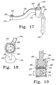
- the arm 234 is shown in Fig. 17 and comprises a pivot collar 244, an offset shaft 246, a first end 243, and a second end 245.
- the pivot collar 244 comprises two slots 248 and 250 which receive a lock-rod (not shown) coupled to the spring-loaded release handle 242 to maintain the arm 234 in a position in either a stowed position or a use position.
- the arm 234 and therefore leg support 216 pivots about an axis 252 shown in Fig. 15.
- the ball-lock mechanism 236 comprises a housing 254, an handle assembly 256, a ball mount 258, and a spring bias assembly 260.
- the ball-lock mechanism 236 is moveable between a position wherein the ball mount 258 is free to pivot relative to the housing 254 and position wherein ball mount 258 is constrained from moving relative to the housing 254.
- the ball mount 258 comprises a spherical portion 262 and a shaft 264 configured to engage with a mount 266 (best seen in Fig. 21) of the cushion assembly 238.
- the handle assembly 256 is used to engage the ball-lock mechanism 236.
- the handle assembly 256 comprises a bent shaft 268 and a grip 270.
- the handle assembly 256 is actuated such that the shaft 268 is rotated in the direction of arrow 272 to thereby move the ball-lock mechanism 236 between locked and unlocked positions.
- shaft 268 is coupled to a cam 274 that supports a flange 276 of the spring bias assembly 260.
- the flange 276 supports four spring washers 278 that in turn support a cradle 280 that supports the spherical portion 262 of ball mount 258.
- the cam 274 is four sided with two opposing sides having a thickness smaller than the other two opposing sides.
- a portion of housing 254 is removed to define a slot 292 that is configured to receive the shaft 264 of ball mount 258 when the leg support 216 is in a stowed position.
- the shaft 264 has two sides 288 and 290 that define a tapered cross-section of shaft 264. The tapering assists the shaft in nesting in the slot 292 to prevent the cushion assembly 238 from moving while the leg support 216 is stowed.
- leg support 216 permits the leg assembly to be rotated about an axis 294 shown in Fig. 20 in the direction of arrow 296. Once the leg support is rotated about axis 294, the cushion assembly 238 is positionable relative to the ball-lock mechanism 236 to a plurality of positions such as, for example, in direction 286 toward the use position shown in Fig. 16.
- the cushion assembly 238 comprises a molded foam covering 298 coupled to a support structure 300.
- the mount 266 is coupled to structure 300 through two fasteners 302.
- Mount 266 includes a through-hole 304 that is positioned such that when shaft 264 of ball mount 258 is positioned in a blind hole 306 in a lower surface 308 of mount 266, the cushion assembly 238 is coupled to the ball mount 258 and secured with a fastener 305.
- the covering 298 is molded to form two ridges 310 and 312 in a surface 532 of covering 298.
- the ridges 310 and 312 are spaced apart such that a strap 314 is positionable between the ridges 310 and 312.
- Strap 314 is used as a securing strap to assist a patient in maintaining their legs positioned in the cushion assembly 238 during labor.
- the ridges 310 and 312 assist in maintaining the strap 314 positioned without sliding along the longitudinal length of the cushion assembly 238.
- Cushion assembly 238 further includes a molded ridge 316 that extends about the perimeter of the cushion assembly 238 to eliminate sharp edges.
- the covering 298 comprises an over-molded foam.
- the covering 298 covers structure 300 that is a unitary metal sheet.
- the metal sheet may be replaced with a rigid plastic material such as ABS.
- Structure 300 includes a main portion 318 that has several through-holes 320 that are configured to allow the over-molding to adhere between an upper portion and lower portion.
- Structure 300 also includes two flanges 324 and 326 extending longitudinally along a length of main portion 318. An additional flange 322 is coupled to main portion 318 to provide support for a lower leg hanging over the edge of cushion assembly 238.
Abstract
Description
- The present disclosure relates to accessories that attach to birthing beds to support the body of a patient during obstetric labor and delivery. More particularly, the present disclosure relates to patient support accessories that attach to birthing beds or birthing bed accessory frames and that are configured to engage and support limbs of the body of a patient during labor and delivery.
- During obstetric delivery in which a patient is in a reclining position, it is desirable for the legs of a patient to be positioned by a caregiver so as not to be supported by an underlying table surface. In many situations is important to have a limb-support apparatus permitting flexure of the knee joints of a patient by a sufficient amount to place the patient in a desired position for delivery of a child.
- The present disclosure comprises one or more of the following features alone or in any combination, may comprise patentable subject matter:
- A limb support is configured to be secured to a patient-support apparatus having two generally parallel longitudinal members spaced apart such as a birthing bed for obstetric delivery. The limb support, embodied as a foot support, comprises a foot-receiving portion which is configured to be adjustable to support the foot of a patient thereon, especially, for example, a patient in labor for obstetric delivery. The foot support may be shaped to engage a foot of a patient.
- The foot support may further comprise a frame configured to pivot about both a vertical axis and a horizontal axis in relation to the patient support apparatus. A pair of locks configured to block pivoting movement of the frame about an associated axis is coupled to the frame. The frame includes a U-shaped bracket having a pair of walls positioned in a parallel spaced-apart relation to one another. Each wall is formed to include a blind slot having a termination and arranged to open away from the horizontal axis of rotation.
- A lock release actuator is coupled to the frame to receive an actuation force from a caregiver to simultaneously unlock both the vertical rotation-blocking lock and the horizontal rotation-blocking lock to allow the caregiver to move the foot support to a desired position. In some embodiments, the lock release actuator may be embodied as a grip. The grip is coupled to a crossmember positioned such that portions of the crossmember are received by both slots for slidable movement therein. The crossmember is coupled to the locks via a pair of cables, each cable being coupled to an associated rotation-blocking lock.
- The grip is generally J-shaped and arranged to receive a hand of a caregiver for application of the actuation force. The grip is configured to transmit the actuation force to the locks regardless of where the actuation force is applied along the length of the grip.
- When an actuation force is applied to the grip along a generally longitudinal axis of the foot support frame, the crossmember will move toward the opening of both slots in a generally symmetric motion. However, the arrangement of the slot terminations allows the crossmember to form a pivot axis about the termination if an oblique actuation force is applied to the grip. Thus, while one end of the crossmember pivots about the slot termination, the other end is free to move toward the slot opening allowing the crossmember to sufficiently displace the cables so that the associated locks are released.
- The limb support may further comprise a leg support mounted on the foot support and moveable from a stowed position below the foot support to one of a number of use positions. The leg support may be pivotably coupled to the foot support through a pivot-coupler that is coupled to the foot support. The leg support comprises an arm, a ball-lock assembly coupled to the arm, and a cushion assembly coupled to the ball-lock assembly to receive and support a portion of a leg of an obstetric patient. The cushion may be configured to conform to the contours of the body of the patient. In some embodiments, the leg support may have an upwardly facing surface which is convex in shape.
- The pivot-coupler has a body and a spring-loaded release handle. The pivot-coupler also has an internal pivot shaft about which the arm pivots.
- The arm comprises a pivot collar and an offset shaft. The pivot collar is formed to include two slots which receive a lock-rod coupled to the spring-loaded release handle to maintain the arm in a position in either a stowed position or a use position. The arm, and therefore the leg support, are able to pivot about an axis to move the leg support from the stowed position to the use position to receive the leg of the patient.
- The ball-lock mechanism includes a housing, a release handle, a ball mount, and a spring bias assembly. The ball-lock mechanism is moveable between an unlocked position wherein the ball mount is free to pivot relative to the housing and a locked position wherein the ball mount is inhibited from moving relative to the housing. The ball mount comprises a spherical portion and a shaft configured to engage with a mount coupled to the cushion assembly. The release handle is used to engage the ball-lock mechanism.
- The release handle includes a bent shaft and a grip. The release handle is rotated by the caregiver to move the ball-lock mechanism between the locked and unlocked positions. A cam supports a flange of the spring bias assembly. The flange supports a plurality of spring washers that in turn support a cradle that receives the spherical portion of the ball mount. The cam is four sided with two opposing sides having a thickness smaller than the other two opposing sides. Thus, rotation of the cam ninety degrees in a prescribed direction changes the displacement of the flange and therefore the deflection of the spring washers.
- When the force exerted by spring washers on the cradle, and therefore the ball mount, is minimal, the ball mount is pivotable in a plurality of directions about the center of the spherical portion. When the cam is rotated in an opposite direction, the cradle is urged against the spherical portion which urges the spherical portion against an annular surface of the housing to cause the ball mount to be restrained from moving.
- The invention will now be described by way of example with reference to the accompanying drawings in which:
- Fig. 1 is a perspective view from a foot end corner of a patient-support apparatus of the present disclosure showing a pair of limb supports coupled to an articulable yoke and a left limb support being shown in an articulated position in phantom;
- Fig. 2 is an exploded perspective view of illustrative components included in a limb support lock release mechanism of the patient-support apparatus of Fig. 1;
- Fig. 3 is a plan view of a limb support embodied as a foot support (with a cover removed) showing (from left to right) an outer grip, a lock release grip, a frame, and horizontal and vertical pivot mounts;
- Fig. 4 is a bottom view of the foot support of Fig. 3 showing the foot support with portions removed;
- Fig. 5 is a perspective view of the underside of the foot support of Fig. 3;
- Fig. 6 is a side elevation view of the foot support of Fig. 3;
- Fig. 7 is a perspective view of the lock release mechanism of Fig. 4 showing the grip coupled to a crossmember positioned in a pair of guide slots formed in a guide bracket and a pair of release cables coupled to the crossmember on first ends;
- Fig. 8 is a perspective view of a locking mechanism showing a shaft coupled to a mount;
- Fig. 9 is an enlarged plan view of the horizontal and vertical pivot mounts of Fig. 3;
- Fig. 10 is a perspective view similar to Fig. 1 showing the foot supports (and an accessory leg support mounted to each foot support) pivoted about both a vertical axis and a horizontal axis to move the foot supports to an upright out-of-the-way position;
- Fig. 11 is a plan view similar to Fig. 3 showing an outer grip removed;
- Fig. 12 is a perspective view of a patient-support apparatus in accordance with a second embodiment of the present disclosure showing a pair of foot supports further including a calf support mounted to and articulable relative to the foot support;
- Fig. 13 is a perspective view of the patient-support apparatus of Fig. 12 with each of the foot supports articulated to an out-of-the-way position to permit a caregiver access to a seat support section area of the patient-support apparatus;
- Fig. 14 s a perspective view of the patient-support apparatus of Fig. 12 with the foot supports and calf support articulated such that the calf supports are positioned for a patient to rest a portion of the patient's leg on the calf support during birthing labor;
- Fig. 15 is a perspective view of the calf support mounted to the foot support as shown in Fig. 13, the calf support shown articulated relative to the foot support and the calf support in a stowed position in phantom;
- Fig. 16 is a perspective view similar to Fig. 15 with the calf support articulated about a multi-axis pivot mount relative to the foot support and an intermediate position in phantom;
- Fig. 17 is a perspective view of a support arm and multi-axis pivot mount of a calf support of the illustrative embodiment of Fig. 12;
- Fig. 18 is a top view of the multi-axis pivot mount and a portion of the support arm of Fig. 17;
- Fig. 19 is a sectional view of the multi-axis pivot mount of Fig. 18 taken along lines 19-19;
- Fig. 20 is an exploded perspective view of illustrative components of the support arm and multi-axis pivot mount of Figs. 15 and 16;
- Fig. 21 is a perspective view of a cushion assembly of the calf support of Fig. 14;
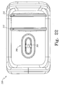
- Fig. 22 is a bottom view of the cushion assembly of Fig. 21;
- Fig. 23 is a cross-sectional view of the cushion assembly of Fig. 22 taken along lines 23-23; and
- Fig. 24 is a perspective view of a mechanical insert of the cushion assembly of Fig. 22.
- A patient-
support apparatus 10 for obstetric labor and delivery includes a pair of limb supports 12 and 14 embodied as foot supports 12 and 14. Foot supports 12 and 14 are of a similar construction withfoot support 12 being a patient right hand version andfoot support 14 being a patient left hand version. As depicted in Fig. 1, foot supports 12 and 14 are articulable relative to ayoke 16 ofpatient support apparatus 10 withfoot support 14 being shown in an articulated position (in phantom). Articulation of the foot supports 12 and 14 permits a caregiver to adjust the position of the foot supports 12 and 14 to position the feet of a patient supported on aseat deck 18 andmattress 20 during the birthing process. - In the foregoing discussion, the structure of
foot support 14 will be discussed and it should be understood thatfoot support 12 operates in a substantially similar manner with the only difference being thatfoot support 14 is a left hand version and afoot support 12 is a right hand version. As shown in Fig. 1, amain portion 22 offoot support 14 is pivotable about anaxis 24 that is generally horizontal. Additionally, amount portion 26 offoot support 14 is pivotable about a generallyvertical axis 28 that thereby pivots theentire foot support 14 aboutaxis 28. -
Foot support 14 is shown with covers omitted to show the mechanical structure of thefoot support 14, as suggested in Fig. 3.Foot support 14 is pivotable aboutaxis 28 in a plurality of directions as depicted byarrow 30 as shown, for example, in Fig. 1. Referring once again to Fig. 3,main portion 22 is pivotably coupled to themount portion 26 and pivotable aboutaxis 24 as depicted byarrow 32. Themain portion 22 comprises alock release 15 coupled to aframe 34, mount 36 coupled to frame 34 and configured to engage agas spring 38 which acts as a counterbalance to resists rotation ofmain portion 22 aboutaxis 24 so as to assist a caregiver in adjusting the position ofmain portion 22 aboutaxis 24 when the load of a patient's foot is supported onfoot support 14.Main portion 22 further comprises abracket 40 coupled to frame 34 and positioned to support alocking mechanism 42 which is biased to a locked position to resists rotation ofmain portion 22 relative to mountportion 26 offoot support 14. - The
main portion 22 further comprises aflange 44 coupled to opposingsidewalls frame 34 as shown in Fig. 3.Flange 44 supports tworelease cable assemblies Release cable 46 is coupled to lockingmechanism 42 at one end ofrelease cable 46 and is actuable to release lockingmechanism 42 to permitmain portion 22 to move aboutaxis 24 relative to mountportion 26.Release cable 48 is coupled to a locking mechanism 50 (best seen in Fig. 5) and is actuable to release lockingmechanism 50 to permitmount portion 26 to pivot aboutaxis 28 and the direction ofarrow 30. - The
main portion 22 further comprises anouter grip 52 that is U-shaped and is coupled to the outer surfaces ofwalls frame 34 as shown in Fig. 3. Theouter grip 52 is accessible by a user to guidefoot support 14 whenfoot support 14 is repositioned aboutaxes main portion 22 still further comprises aguide bracket 58 coupled toframe 34. Theguide bracket 58 has twoslots crossmember 64 of arelease handle 66 such that the crossmember is free to move relative to guidebracket 58 within theslots crossmember 64 has twoapertures release cables grip portion 72 that is accessible by a user to grip and thereby actuaterelease cables foot support 14 aboutaxes 24 and/or 28. -
Release cables inner cable 76 which moves relative to outer sheath 74, as shown best in Figs. 4 and 7. Each of therelease cables engagement end 78 received inapertures release cable assemblies flange 44 by afastener assembly 80 that maintains the outer sheath 74 of eachcable frame 34. Thus, whengrip portion 72 is actuated relative to frame 34 such as in the direction ofarrow 82, theinner cables 76 of eachrelease cable mechanisms foot support 14 relative to theyoke 22. - The locking
mechanisms inner cables 76 are pulled toward the lockingmechanisms crossmember 64 in a direction opposite ofarrow 82, as shown in Fig. 7. Theslots terminations mechanisms inner cables 76 ofrelease cables crossmember 64 to engageterminations crossmember 64 relative to aguide bracket 58 overcomes the bias of lockingmechanisms locking mechanisms crossmember 64 is free to move in a plurality of directions in a plane of movement defined byslots guide bracket 58. - Because
crossmember 64 is free to move in a plurality of directions, a user need not activate release handle 66 in the direction ofarrow 82 in order to release lockingmechanisms grip portion 72 to move release handle 66 in the direction of thearrow 108, the motion is transferred to crossmember 64 such thatcrossmember 64 maintains contact withtermination 86 ofslot 62 andcrossmember 64 moves within theslot 60 such thatcrossmember 64 pivots relative totermination 86. - In addition,
crossmember 64 is free to move in the plane of movement defined byslots slots inner cables 76 move relative to outer sheaths 74 ofrelease cable locking mechanisms mechanisms - Once again referring again to Fig. 3,
locking mechanism 42 is pinned tobracket 40 by a retainingpin 88 andhairpin fastener 90 that retainspin 88 onbracket 40. As suggested in Fig. 5,locking mechanism 42 is also pinned to twoflanges frame portion 96 of main portion 330 retainingpin 88 andhairpin fastener 90 couple thelocking mechanism 42 to theflanges mechanism 42 is pivotable relative tobracket 40 aboutpin 88 and relative toflanges locking mechanism 42 maintains the distance between thepins 88 and prevents rotation ofmain portion 22 aboutaxis 24. By changing the distance betweenpin 88 andbracket 40 andpin 88 inflanges main portion 22 pivots aboutaxis 24 to change the position offoot support 14. - Locking
mechanism 50 is coupled to aframe 96 ofmount portion 26 through apin 98, as shown in Fig. 9. Lockingmechanism 50 is also coupled to acam plate 100 of acam assembly 110 through apin 102.Pins mechanism 50 by a pair ofe-rings Cam assembly 110 further comprises akeyed collar 112 that is configured to engage a shaft to onyoke 22 of patient-support apparatus 10. Thecollar 112 comprises akeyed slot 114 that engages with a key (not shown) on the shaft (not shown) of theyoke 22. The shaft is fixed to theyoke 22 and keyedcollar 112 is restrained from rotation about the shaft by the engagement of thekeyed slot 114 with the key of the shaft. -
Cam assembly 110 is pivotable relative to frame 96 ofmount portion 26 aboutaxis 28. Thelocking mechanism 50 prevents rotation of thecam assembly 110 relative to frame 96 when the locking mechanism is engaged. When the locking mechanism is released anouter housing 116 of lockingmechanism 50 is free to move along ashaft 118 that thereby permitsframe 96 ofmount portion 26 to rotate relative tocam assembly 110 to a new orientation. Thecam assembly 110 stays in the same or relative position as it relates to theyoke 22, but themount portion 26 and thereby the remainder of thefoot support 14 pivots relative to theyoke 22. - The locking
mechanisms mechanism 42 shown in Fig. 8. Thelocking mechanism 42 is a wrap spring mechanism in which a wrap spring (not shown) engages theshaft 118 when the wrap spring is in a relaxed positioned. The inner diameter of the wrap spring is slightly smaller than the outer diameter of theshaft 118 such that when the wrap spring engagesshaft 118 the spring is precluded from movement along the longitudinal length of theshaft 118 thereby securing the spring to the shaft to 118. Lockingmechanism 42 further comprises anouter housing 116 that is engaged with the spring. - The
housing 116 comprises a cylindricalmain portion 128 and twoflanges main portion 128. Thehousing 116 also comprises a connectingflange 130 that is used to connect to thehousing 116 to an external member (not shown). Theflanges cable 46 to transmit the actuation force to the flanges. When theflanges arrow 132 in response to the actuation force transmitted bycable 46, the wrap spring, internal to the housing, is configured such that the inner diameter of the spring body is enlarged so that the spring is free to move alongshaft 118. When theflanges shaft 118 and thus prevents thehousing 116 from moving relative to theshaft 118. - The
shaft 118 includes aflange 120 positioned at one end which prevents the spring and therefore thehousing 116 from sliding off the end of theshaft 118. At the end of the shaft opposite to theflange 120 is aneyelet 122 coupled to theshaft 118 to connect theshaft 118 to another external member. In use, arelease cable 48 is coupled to the locking mechanisms such that theinner cable 76 is connected to flange 124 and the outer sheath 74 is connected to flange 126 so that movement of the release handle 66 as discussed above causes theflanges arrow 132 thereby releasing thelocking mechanism 42. This permits the adjustment of thefoot support 14 relative toyoke 22 to a plurality of positions aboutaxis 24. The release of lockingmechanism 50 occurs in a similar fashion and allowsfoot support 14 to be adjusted aboutaxis 28. - For example, the foot supports 12 and 14 are each shown in a home position in Fig. 1 and shown articulated about both the generally vertical and generally horizontal axes to an upright out-of-the-way position as shown in Fig. 10. The foot supports 12 and 14 are adjustable to a plurality of positions about the generally horizontal and generally vertical axes so that the
foot support - In the illustrative embodiment of Fig. 10, two leg supports 150 and 152 are coupled to foot supports 12 and 14 respectively. In addition, the
foot support 12 comprises afoot receiving cover 140, a bellows cover 142 covering a horizontal pivoting mechanism, and a mount cover 138. Thefoot support 14 comprises a foot-receiving cover 144, abellows 148, and amount cover 146. - In a second illustrative embodiment of a patient-
support apparatus 210 of Fig. 12, two limb supports 216 and 218 are coupled to foot supports 12 and 14, respectively. As suggested in Figs. 12-14, theleg support 216 is moveable between a stowed position belowfoot support 16 as shown in Fig. 12 and any of a number of use positions as shown in Fig. 14. Theleg support 216 andleg support 218 are similar in structure with theleg support 216 being configured as a right-hand version and theleg support 218 being configured as a left-hand version. The structure ofleg support 216 will be discussed in detail below. It should be understood that the description ofleg support 216 is applicable to the general structure ofleg support 218 with the only difference being the handedness of the two leg supports 216 and 218. - As shown in Figs. 13 and 14,
leg support 216 is pivotably coupled tofoot support 12 through a pivot-coupler 232 that is coupled tofoot support 16. Theleg support 216 comprises anarm 234, a ball-lock assembly 236 coupled to thearm 234, and acushion assembly 238 coupled to the ball-lock assembly 236. Referring now to Fig. 20, the pivot-coupler 232 includes abody 240 having afirst knuckle 235, asecond knuckle 237, and a spring-loaded release handle 242 coupled to thefirst knuckle 235. The pivot-coupler 232 also has aninternal pivot shaft 233 about which arm 234 pivots. - The
arm 234 is shown in Fig. 17 and comprises apivot collar 244, an offsetshaft 246, a first end 243, and a second end 245. Thepivot collar 244 comprises twoslots arm 234 in a position in either a stowed position or a use position. Thearm 234 and thereforeleg support 216 pivots about anaxis 252 shown in Fig. 15. - Details of the ball-
lock mechanism 236 are shown in Figs. 18 and 19 and the ball-lock mechanism 236 comprises ahousing 254, anhandle assembly 256, a ball mount 258, and a spring bias assembly 260. The ball-lock mechanism 236 is moveable between a position wherein the ball mount 258 is free to pivot relative to thehousing 254 and position wherein ball mount 258 is constrained from moving relative to thehousing 254. The ball mount 258 comprises aspherical portion 262 and ashaft 264 configured to engage with a mount 266 (best seen in Fig. 21) of thecushion assembly 238. Thehandle assembly 256 is used to engage the ball-lock mechanism 236. - The
handle assembly 256 comprises abent shaft 268 and agrip 270. Thehandle assembly 256 is actuated such that theshaft 268 is rotated in the direction ofarrow 272 to thereby move the ball-lock mechanism 236 between locked and unlocked positions. Referring now to Fig. 19,shaft 268 is coupled to acam 274 that supports aflange 276 of the spring bias assembly 260. Theflange 276 supports fourspring washers 278 that in turn support acradle 280 that supports thespherical portion 262 of ball mount 258. Thecam 274 is four sided with two opposing sides having a thickness smaller than the other two opposing sides. Thus, rotation of thecam 274 ninety degrees in the direction ofarrow 272 changes the displacement offlange 276 and therefore the deflection ofspring washers 278. As shown in Fig. 19, the displacement ofspring washers 278 is at a minimum. In the position of Fig. 19, the force exerted byspring washers 278 oncradle 280 and therefore ball mount 258 is minimal such that the ball mount 258 is pivotable in a plurality of directions about the center of thespherical portion 262. When thecam 274 is rotated ninety degrees, thecradle 280 is urged against thespherical portion 262 which is thereby urged against anannular surface 282 of thehousing 254 such that the ball mount 258 is restrained from moving. - Referring now to Fig. 23, a portion of
housing 254 is removed to define aslot 292 that is configured to receive theshaft 264 of ball mount 258 when theleg support 216 is in a stowed position. Theshaft 264 has twosides shaft 264. The tapering assists the shaft in nesting in theslot 292 to prevent thecushion assembly 238 from moving while theleg support 216 is stowed. - The structure of
leg support 216 permits the leg assembly to be rotated about anaxis 294 shown in Fig. 20 in the direction ofarrow 296. Once the leg support is rotated aboutaxis 294, thecushion assembly 238 is positionable relative to the ball-lock mechanism 236 to a plurality of positions such as, for example, indirection 286 toward the use position shown in Fig. 16. - Referring now to Figs. 21-24, the
cushion assembly 238 comprises a molded foam covering 298 coupled to asupport structure 300. Themount 266 is coupled to structure 300 through twofasteners 302.Mount 266 includes a through-hole 304 that is positioned such that whenshaft 264 of ball mount 258 is positioned in ablind hole 306 in alower surface 308 ofmount 266, thecushion assembly 238 is coupled to the ball mount 258 and secured with afastener 305. - The covering 298 is molded to form two
ridges ridges strap 314 is positionable between theridges Strap 314 is used as a securing strap to assist a patient in maintaining their legs positioned in thecushion assembly 238 during labor. Theridges strap 314 positioned without sliding along the longitudinal length of thecushion assembly 238.Cushion assembly 238 further includes a moldedridge 316 that extends about the perimeter of thecushion assembly 238 to eliminate sharp edges. The covering 298 comprises an over-molded foam. - The covering 298 covers
structure 300 that is a unitary metal sheet. In some embodiments, the metal sheet may be replaced with a rigid plastic material such as ABS.Structure 300 includes amain portion 318 that has several through-holes 320 that are configured to allow the over-molding to adhere between an upper portion and lower portion.Structure 300 also includes twoflanges main portion 318. Anadditional flange 322 is coupled tomain portion 318 to provide support for a lower leg hanging over the edge ofcushion assembly 238.
Claims (26)
- A lock release 15 for a limb support 12, 14 of a patient-support apparatus 10 comprising:a frame 34 coupleable to the patient-support apparatus 10 configured to pivot about a vertical axis 28 and a horizontal axis 24 in relation to the patient-support apparatus 10, the frame 34 including a guide bracket 58 having a pair of spaced-apart walls 59 positioned in a parallel relation to one another, each wall 59 formed to include a blind slot 60, 62 having a termination 84, 86 and an open end, and first and second pivot locks 42, 50 configured to block pivoting of the frame 34 about the vertical and horizontal axes 28, 24 relative to the patient-support apparatus 10,a crossmember 64 received by the slots 60, 62 for slidable movement therein, the crossmember 64 being coupled to the first and second pivot locks 42, 50, anda grip 72 coupled to the crossmember 64 and arranged for application of an actuation force thereto to unlock the first and second pivot locks 42, 50.
- The lock release 15 of claim 1, wherein the slots 60, 62 cooperate to define a plane of movement for the crossmember 64.
- The lock release 15 of claim 2, wherein the open end of each slot opens toward the grip 72.
- The lock release 15 of either claim 2 or claim 3, wherein the grip 72 is configured to receive the actuation force at any point along the length of the grip parallel to the plane of movement to transmit the actuation force to the crossmember 64.
- The lock release 15 of any one of claims 2 to 4, wherein the grip 72 is J-shaped and coupled on one end to the crossmember 64 adjacent to one of the spaced-apart walls 59.
- A lock release 15 for a limb support 12, 14 of a patient-support apparatus 10 comprising:a frame 34 coupleable to the patient-support apparatus 10 and configured to pivot about a first axis 24 and a second axis 28 in relation to the patient-support apparatus 10, the frame 34 including a first axis pivot lock 42 and a second axis pivot lock 50 configured to block pivoting movement of the frame 34 about the first and second axes 24, 28 in relation to the patient-support apparatus 10,an actuator 66 mounted to the frame 34, the actuator 66 being coupled to the first axis and second axis pivot locks 42, 50 and configured to simultaneously release the locks 42, 50 in response to an application of an actuation force to allow pivotable movement of the frame 34 in relation to the patient-support apparatus 10, andan actuator handle 72 coupled to the actuator 66, the handle 72 defining a plane of movement and configured to transmit to the actuator 66 an actuation force applied at any point along the length of the handle 72 along the plane of movement.
- The lock release 15 of claim 6, further comprising a foot support 12, 14 mounted to the frame 34.
- The lock release 15 of either claim 6 or claim 7, wherein the actuator 66 includes a guide bracket 58 having a pair of spaced-apart walls 59 positioned in a parallel relation to one another, each wall 59 formed to include a blind slot 60, 62 having a termination 84, 86 and an open end.
- The lock release 15 of claim 8, wherein each slot 60, 62 open end opens toward the handle 72.
- The lock release of either claim 9 or claim 10, further comprising a crossmember 64 received by the slots 60, 62 for slidable movement therein, the crossmember 64 being coupled to the first and second axis pivot locks 42, 50.
- The lock release of claim 10, wherein the actuator handle 72 is coupled to the crossmember 64 adjacent to one of the spaced-apart walls 59.
- The lock release of any one of claims 8 to 11, wherein the crossmember 64 is biased to engage the terminations 84, 86 of the slots 60, 62.
- The lock release of any one of claims 6 to 12, wherein the actuator handle 72 is a J-shaped grip.
- A lock release 15 for use with a patient-support apparatus comprising:a foot support 12, 14 coupleable to the patient-support apparatus 10 and configured to pivot about first and second axes 24, 28 in relation to the patient-support apparatus 10, the foot support 12, 14 having a U-shaped guide bracket 58 formed to include a pair of parallel spaced apart slots 60, 62 defining a plane of movement, each slot 60, 62 formed to include a termination 84, 86 and an open end, and a first and a second lock 42, 50 to block pivoting of the foot support 12, 14 about the first and second axes 24, 28 in relation to the patient-support apparatus 10,a crossmember 64 positioned in the slots 60, 62 for movement along the plane of movement relative to the guide bracket 58 and further coupled to the first and second locks 42, 50 to simultaneously release the locks 42, 50 to allow pivoting of the foot support 12, 14 about the first and second axes 24, 28 in relation to the patient-support apparatus 10, anda release actuator 66 coupled to the crossmember 64 for application of an actuation force to move the crossmember 64 in relation to the guide bracket 58 to simultaneously release the first and second locks 42, 50.
- The lock release 15 of claim 14, wherein the release actuator is a J-shaped grip 72, the grip 72 coupled on one end to the crossmember 64 and configured for application of an actuation force applied along the plane of movement at any point along the length of the grip 72.
- The lock release 15 of either claim 14 or claim 15, wherein the foot support 12, 14 includes a frame 34 having spaced-apart sidewalls 54, 56 and an outer grip 52 extending therebetween.
- The lock release of any one of claims 1 to 13 and 16, further comprising a mount portion 26 extending between the foot support 12, 14 and the patient-support apparatus 10.
- The lock release 15 of claim 17 as dependent on any one of claims 1 to 5, wherein the frame 34 comprises a foot support 12, 14.
- The lock release 15 of claim 17, further comprising a gas spring 38 coupled to the mount portion 26 on one end and to the frame 34 on an end opposite the mount portion 26.
- The lock release 15 of claim 19, wherein the gas spring 38 is configured to resist pivoting of the frame 34 about the horizontal axis 24 to counterbalance a load applied to the frame 34 by a limb of a patient.
- The lock release 15 of any one of claims 14 to 16, wherein the open end of each slot 60, 62 opens toward the outer grip 52.
- The lock release 15 of any one of claims 1 to 5, 14 to 16 and 21, wherein the crossmember 64 is biased to engage the terminations 84, 86 of the slots 60, 62.
- The lock release 15 of any one of claims 2, 3, 10 or 14 to 16, wherein the crossmember 64 is configured for movement upon application of the actuation force between a first release position where a portion of the crossmember 64 maintains contact with a respective slot termination 84, 86 to establish a pivot point thereupon while an opposite end of the crossmember 64 moves toward the open end of the slot 60, 62 to simultaneously unlock the first and second locks 42, 50, and a second release position where portions of the crossmember 64 move generally symmetrically along the slots 60, 62 from the termination 84, 86 toward the open end to simultaneously unlock the first and second locks 42, 50.
- The lock release 15 of any one of claims 1 to 5, 10, 11 and 24 to 16, wherein the lock release 66 further comprises a first cable 46 coupled to the first lock 42 and a second cable 48 coupled to the second lock 50, and the crossmember 64 is formed to include a pair of apertures 68, 70, each aperture 68, 70 configured to receive an end of a cable 78.
- The lock release of any one of claims 1 to 13 and 16, wherein the first and second locks 42, 50 each include an outer housing 116 coupled to the frame 34, a wrap spring positioned to engage the housing 116, a shaft 118 extending through the wrap spring, and a first and a second flange 124, 126 positioned in a spaced-apart relation and coupled to opposing sides of the outer housing 116, the flanges 124, 126 coupled to the lock release 15.
- The lock release 15 of claim 25, wherein the flanges 124, 126 are configured to move toward one another in response to the actuation force being applied to cause an inner diameter of the wrap spring to enlarge so that the wrap spring is free to move along the shaft 118.
Applications Claiming Priority (2)
| Application Number | Priority Date | Filing Date | Title |
|---|---|---|---|
| US73782005P | 2005-11-17 | 2005-11-17 | |
| US80384106P | 2006-06-02 | 2006-06-02 |
Publications (3)
| Publication Number | Publication Date |
|---|---|
| EP1787619A2 true EP1787619A2 (en) | 2007-05-23 |
| EP1787619A3 EP1787619A3 (en) | 2009-01-21 |
| EP1787619B1 EP1787619B1 (en) | 2012-02-22 |
Family
ID=37762633
Family Applications (11)
| Application Number | Title | Priority Date | Filing Date |
|---|---|---|---|
| EP06255891A Active EP1787614B1 (en) | 2005-11-17 | 2006-11-17 | Hospital bed caster control system |
| EP06255883A Active EP1787618B1 (en) | 2005-11-17 | 2006-11-17 | Birthing bed calf support |
| EP12151513.4A Active EP2486907B1 (en) | 2005-11-17 | 2006-11-17 | Patient Support Apparatus Including Storage Structure |
| EP10179047A Active EP2260820B1 (en) | 2005-11-17 | 2006-11-17 | Birthing bed calf support |
| EP10189297A Active EP2305201B1 (en) | 2005-11-17 | 2006-11-17 | Hospital bed caster control system |
| EP06255908A Active EP1787619B1 (en) | 2005-11-17 | 2006-11-17 | Birthing bed calf support |
| EP11165823A Active EP2359794B1 (en) | 2005-11-17 | 2006-11-17 | Stowing Birthing Bed Foot Section |
| EP06255878A Expired - Fee Related EP1787617B1 (en) | 2005-11-17 | 2006-11-17 | Birthing bed lift off foot section |
| EP12151516A Withdrawn EP2484332A1 (en) | 2005-11-17 | 2006-11-17 | Patient support apparatus including storage structure |
| EP10190040.5A Active EP2316402B1 (en) | 2005-11-17 | 2006-11-17 | Birthing bed lift off foot section |
| EP06255877A Active EP1787616B1 (en) | 2005-11-17 | 2006-11-17 | Stowing birthing bed foot section |
Family Applications Before (5)
| Application Number | Title | Priority Date | Filing Date |
|---|---|---|---|
| EP06255891A Active EP1787614B1 (en) | 2005-11-17 | 2006-11-17 | Hospital bed caster control system |
| EP06255883A Active EP1787618B1 (en) | 2005-11-17 | 2006-11-17 | Birthing bed calf support |
| EP12151513.4A Active EP2486907B1 (en) | 2005-11-17 | 2006-11-17 | Patient Support Apparatus Including Storage Structure |
| EP10179047A Active EP2260820B1 (en) | 2005-11-17 | 2006-11-17 | Birthing bed calf support |
| EP10189297A Active EP2305201B1 (en) | 2005-11-17 | 2006-11-17 | Hospital bed caster control system |
Family Applications After (5)
| Application Number | Title | Priority Date | Filing Date |
|---|---|---|---|
| EP11165823A Active EP2359794B1 (en) | 2005-11-17 | 2006-11-17 | Stowing Birthing Bed Foot Section |
| EP06255878A Expired - Fee Related EP1787617B1 (en) | 2005-11-17 | 2006-11-17 | Birthing bed lift off foot section |
| EP12151516A Withdrawn EP2484332A1 (en) | 2005-11-17 | 2006-11-17 | Patient support apparatus including storage structure |
| EP10190040.5A Active EP2316402B1 (en) | 2005-11-17 | 2006-11-17 | Birthing bed lift off foot section |
| EP06255877A Active EP1787616B1 (en) | 2005-11-17 | 2006-11-17 | Stowing birthing bed foot section |
Country Status (4)
| Country | Link |
|---|---|
| US (10) | US7698760B2 (en) |
| EP (11) | EP1787614B1 (en) |
| JP (5) | JP2007167628A (en) |
| DE (3) | DE602006019044D1 (en) |
Cited By (6)
| Publication number | Priority date | Publication date | Assignee | Title |
|---|---|---|---|---|
| WO2013181277A1 (en) * | 2012-05-29 | 2013-12-05 | Medical Technologies Industries | Wound care apparatus and methods for using the same |
| US8615827B2 (en) | 2009-03-03 | 2013-12-31 | Hill-Rom Services, Inc. | Person-support apparatus with movable portions |
| US9125495B2 (en) | 2008-11-27 | 2015-09-08 | Medical Technologies Industries, Inc. | Articulated chair having universal reclining armrest system |
| US9782319B2 (en) | 2008-11-27 | 2017-10-10 | Medical Technology Industries, Inc. | Articulated chair having universal reclining armrest system |
| CN110812081A (en) * | 2019-11-21 | 2020-02-21 | 王运斌 | Intelligent obstetrical device of gynaecology and obstetrics |
| CN111214355A (en) * | 2020-01-21 | 2020-06-02 | 漯河市第一人民医院 | Fixing device and fixing method for burn plastic surgery |
Families Citing this family (78)
| Publication number | Priority date | Publication date | Assignee | Title |
|---|---|---|---|---|
| ATE456351T1 (en) * | 2003-05-21 | 2010-02-15 | Hill Rom Services Inc | HOSPITAL BED |
| US8292327B2 (en) * | 2004-09-15 | 2012-10-23 | Fernando Esteban Araya Moreno | Device for the optional guiding of at least one self-steering wheel of a trolley |
| US9107788B2 (en) * | 2005-10-07 | 2015-08-18 | MediGlider Corp. | Cam mechanism to raise steering wheel of patient transfer device |
| US7698760B2 (en) * | 2005-11-17 | 2010-04-20 | Hill-Rom Services, Inc. | Hospital bed caster control system |
| US7810822B2 (en) | 2006-01-19 | 2010-10-12 | Hill-Rom Services, Inc. | Stretcher having hand actuated caster braking apparatus |
| US8264715B2 (en) * | 2006-04-25 | 2012-09-11 | Ricoh Company, Ltd. | Approach for implementing locked printing with remote unlock on printing devices |
| CZ17216U1 (en) * | 2006-11-09 | 2007-02-05 | Linet, Spol. S R. O. | Guide wheel assembly, especially for hospital bed |
| ES2388569T3 (en) * | 2008-02-07 | 2012-10-16 | Wissner-Bosserhoff Gmbh | Immobilization brake for furniture with rollers, in particular beds, and bed with an immobilization brake of this type |
| JP2009298280A (en) * | 2008-06-12 | 2009-12-24 | Mitaka Koki Co Ltd | Stopper structure of base |
| KR101024850B1 (en) * | 2008-11-20 | 2011-03-31 | 주식회사 메디슨 | Device for controlling a castor |
| CN101904791B (en) * | 2009-06-03 | 2012-02-01 | 安钛医疗设备股份有限公司 | Brake mechanism of operating table foundation |
| ES2394857B1 (en) * | 2010-04-28 | 2013-08-27 | Industrias Hidraulicas Pardo, S.A. | COUPLING SYSTEM AND / OR REPLACEMENT OF THE LIFT AXLE BARS AND THEIR CORRESPONDING ENGINE FOR ARTICULATED MILK BEDS |
| JP5450302B2 (en) * | 2010-07-27 | 2014-03-26 | 株式会社内外 | Braking caster device |
| DE102010046845A1 (en) * | 2010-09-29 | 2012-03-29 | Berchtold Holding Gmbh | operating table |
| CN102442334B (en) * | 2010-10-09 | 2016-04-20 | 深圳迈瑞生物医疗电子股份有限公司 | A kind of central control brake system and trolley type movable medical equipment |
| US8844075B2 (en) | 2010-10-22 | 2014-09-30 | Hill-Rom Services, Inc. | Footboard with partial mattress integration |
| US8522379B2 (en) | 2010-11-15 | 2013-09-03 | Hill-Rom Services, Inc. | Hospital bed foot section with caster cutouts |
| US8341779B2 (en) | 2010-12-06 | 2013-01-01 | Hill-Rom Services, Inc. | Retractable foot caster supports |
| US9173795B2 (en) * | 2011-02-08 | 2015-11-03 | Hill-Rom Services, Inc. | Brake pedal mechanism for hospital bed |
| JP5880933B2 (en) * | 2011-12-19 | 2016-03-09 | 株式会社ジェイ・エム・エス | Combined medical device, extracorporeal circulating blood processing device, and blood reservoir unit |
| US9061547B2 (en) * | 2011-12-23 | 2015-06-23 | Caremed Supply Inc. | Power-operated caster brake mechanism |
| US8484802B1 (en) * | 2012-01-11 | 2013-07-16 | Sunny Castors Co., Ltd. | Combination castor whose castor assemblies are braked and positioned simultaneously |
| US8516656B2 (en) * | 2012-01-11 | 2013-08-27 | Sunny Castors Co., Ltd. | Combination castor whose castor units are braked simultaneously |
| US8418315B1 (en) * | 2012-01-11 | 2013-04-16 | Sunny Castors Co., Ltd. | Combination castor brake system whose castor assemblies are braked and positioned simultaneously |
| CN102755234B (en) * | 2012-07-17 | 2014-08-06 | 西安交通大学 | Laminar flow hospital bed |
| US9074648B2 (en) | 2012-10-12 | 2015-07-07 | Steelcase Inc. | Braking mechanism |
| US9579241B2 (en) | 2012-10-12 | 2017-02-28 | Steelcase Inc. | Support arrangement with activation mechanism |
| DE102012110755A1 (en) * | 2012-11-09 | 2014-05-15 | MAQUET GmbH | Transport trolley for transporting a patient support surface and / or an operating table column of an operating table |
| GB2516051B (en) * | 2013-07-09 | 2016-06-08 | Eschmann Holdings Ltd | Surgical tables |
| GB2518394A (en) * | 2013-09-20 | 2015-03-25 | Sherborne Upholstery Ltd | Adjustable bed |
| US9869004B2 (en) * | 2013-10-18 | 2018-01-16 | American Manufacturing & Engineering Company, Inc. | Article processing fixture |
| US9603764B2 (en) | 2014-02-11 | 2017-03-28 | Medline Industries, Inc. | Method and apparatus for a locking caster |
| KR101527724B1 (en) * | 2014-03-03 | 2015-06-11 | 제이더블유중외메디칼 주식회사 | Nee supporter rotating appartus using bevel gear for medical examination stand |
| US20170014285A1 (en) * | 2014-04-05 | 2017-01-19 | Gayathree Mohan | Emergency mobile labor cot inside ambulance vans |
| JP6258823B2 (en) * | 2014-09-10 | 2018-01-10 | パラマウントベッド株式会社 | Maternity bed |
| US10188573B2 (en) | 2014-11-05 | 2019-01-29 | Allen Medical Systems, Inc. | Boot stirrup |
| JP6454179B2 (en) * | 2015-02-27 | 2019-01-16 | 日本光電工業株式会社 | Posture lock device for medical devices |
| CN106420245A (en) * | 2015-08-04 | 2017-02-22 | 俞小俊 | Height-adjustable obstetric table |
| CN106420238A (en) * | 2015-08-04 | 2017-02-22 | 俞小俊 | Improved obstetric table |
| CN106420240A (en) * | 2015-08-04 | 2017-02-22 | 俞小俊 | Novel obstetric table |
| CN106420247A (en) * | 2015-08-04 | 2017-02-22 | 俞小俊 | Obstetric table |
| US9944121B2 (en) | 2015-08-24 | 2018-04-17 | Darcor Limited | Dual end remote swivel-lock for caster carts and carts equipped with same |
| US9650060B2 (en) | 2015-09-15 | 2017-05-16 | Suncast Technologies, Llc | Swivelable and unidirectional platform truck |
| US10245886B2 (en) | 2015-10-07 | 2019-04-02 | Stryker Corporation | Person support apparatus with braking system |
| CN105708653A (en) * | 2016-01-19 | 2016-06-29 | 魏会芳 | Obstetric bed for obstetrics and gynecology department with leaning angle adjusting function |
| US10835440B2 (en) | 2016-04-01 | 2020-11-17 | Allen Medical Systems, Inc. | Boot carriage for repositioning a surgical boot along a support rod |
| MX2017006308A (en) * | 2016-05-13 | 2018-08-28 | Suncast Technologies Llc | Housekeeping cart with wall protectors. |
| US10980692B2 (en) * | 2016-08-29 | 2021-04-20 | Mobius Imaging, Llc | Table system for medical imaging |
| US10857052B1 (en) * | 2016-08-31 | 2020-12-08 | Pivotal Health Solutions, Inc. | Treatment table for therapeutic treatment, physical rehabilitation and training and method of use |
| CZ2016583A3 (en) | 2016-09-20 | 2018-07-04 | BORCAD Medical a.s. | A medical device for leg support |
| CN106389052A (en) * | 2016-11-03 | 2017-02-15 | 郑州郑先医药科技有限公司 | Multi-purpose type gynecologic bed |
| USD801537S1 (en) * | 2016-11-04 | 2017-10-31 | Larry Ralph Gibson | Support table |
| CN106821641A (en) * | 2017-03-31 | 2017-06-13 | 中山市康满堂生物科技有限公司 | A kind of patient care bed apparatus |
| IT201700062535A1 (en) * | 2017-06-07 | 2018-12-07 | Favero Health Projects Spa | TRANSPORTATION STRUCTURE FOR USE IN HEALTHCARE OR SIMILAR |
| CN107582306B (en) * | 2017-09-07 | 2019-05-28 | 烟台汇通佳仁医疗科技有限公司 | A kind of rotary examination bed of gynemetrics |
| US10336221B2 (en) * | 2017-10-18 | 2019-07-02 | Ami Industries, Inc. | Stowable seat with backrest release |
| US11160705B2 (en) | 2017-10-20 | 2021-11-02 | Stryker Corporation | Adjustable patient support apparatus for assisted egress and ingress |
| CN107753231A (en) * | 2017-11-03 | 2018-03-06 | 赣州市万研教育咨询有限公司 | A kind of pregnant woman is with portable examination couch |
| US10806653B2 (en) | 2017-12-21 | 2020-10-20 | Stryker Corporation | Patient transport apparatus with electro-mechanical braking system |
| CN107928955A (en) * | 2017-12-22 | 2018-04-20 | 太仓市康辉科技发展有限公司 | A kind of more position obstetric tables of the childbirth containing sitting posture |
| CN108635160A (en) * | 2018-04-26 | 2018-10-12 | 吴法贵 | A kind of gynecological examining table easy to use |
| US11229565B2 (en) * | 2018-05-21 | 2022-01-25 | Stryker Corporation | Pedal assembly for a patient support apparatus |
| EP3572239B1 (en) * | 2018-05-23 | 2023-09-20 | Stryker Corporation | Caster assembly with brake assembly having low actuation force |
| US10898000B2 (en) | 2018-07-26 | 2021-01-26 | United Metal Fabricators, Inc. | Leg extension for procedure chair |
| US11090214B2 (en) | 2018-08-06 | 2021-08-17 | United Metal Fabricators, Inc. | Leg support assembly for medical examination device |
| EP3759746B1 (en) | 2019-01-28 | 2021-09-08 | Wacker Chemie AG | Method for applying at least one silicone layer by laser transfer printing |
| CN109646227B (en) * | 2019-02-14 | 2020-08-14 | 孟琴 | Obstetric apparatus for assisting delivery |
| CN110464567B (en) * | 2019-08-27 | 2021-06-04 | 江苏医药职业学院 | Gynaecology and obstetrics is with lying-in woman device of suckleing |
| CN110946723A (en) * | 2019-12-22 | 2020-04-03 | 邵阳学院 | Convenient old person's daily life auxiliary device |
| CN111407380B (en) * | 2020-03-20 | 2021-05-04 | 南阳理工学院 | Intelligent control delivering robot |
| CN111317640A (en) * | 2020-04-02 | 2020-06-23 | 嘉兴新博信息科技有限公司 | Searchlighting and supporting integrated device for gynecological inflammation treatment and repair |
| CN111513966A (en) * | 2020-04-29 | 2020-08-11 | 曹娟 | Obstetric and gynecologic delivery bed and adjusting method thereof |
| CN112155912A (en) * | 2020-10-10 | 2021-01-01 | 新乡市中心医院(新乡中原医院管理中心) | Auxiliary monitoring type obstetric bed for obstetrical department |
| CN112402137B (en) * | 2020-12-31 | 2021-08-24 | 黑龙江省医院 | Intensive care bed and operation method |
| US11772420B2 (en) * | 2021-03-19 | 2023-10-03 | Pipp Mobile Storage Systems, Inc. | Caster wheel brake and anti-swivel system |
| JP7314195B2 (en) | 2021-04-16 | 2023-07-25 | フランスベッド株式会社 | bed equipment |
| CN115363892A (en) * | 2022-09-19 | 2022-11-22 | 河南省中医院(河南中医药大学第二附属医院) | Body support device for natural childbirth |
| CN116115452B (en) * | 2023-02-22 | 2023-09-26 | 吉林省藏舍生物科技有限公司 | Obstetric apparatus for obstetric and gynecologic antenatal delivery |
Citations (4)
| Publication number | Priority date | Publication date | Assignee | Title |
|---|---|---|---|---|
| US6289537B1 (en) * | 2000-02-09 | 2001-09-18 | Stryker Corporation | Patient support |
| WO2001093796A2 (en) * | 2000-06-02 | 2001-12-13 | Hill-Rom Services, Inc. | Foot support for a patient support |
| US20040226094A1 (en) * | 1998-08-07 | 2004-11-18 | Heimbrock Richard H. | OB/GYN stretcher |
| US20060117485A1 (en) * | 2004-12-03 | 2006-06-08 | Brophy Joseph T | Maternity bed foot support and abduction assembly |
Family Cites Families (286)
| Publication number | Priority date | Publication date | Assignee | Title |
|---|---|---|---|---|
| US388995A (en) | 1888-09-04 | Method of rolling slot-rails for cable railroads | ||
| US469837A (en) * | 1892-03-01 | Cloth-cutting machine | ||
| US336577A (en) * | 1886-02-23 | File-holder | ||
| US336578A (en) * | 1886-02-23 | Lubricator | ||
| US964170A (en) | 1905-01-09 | 1910-07-12 | William D Allison | Physician's table. |
| US1469928A (en) | 1920-02-05 | 1923-10-09 | Lazar Leon | Adjustable spotlight for dental chairs |
| US1469841A (en) | 1920-08-05 | 1923-10-09 | Lazar Leon | Adjustable spotlight for dental chairs |
| FR636085A (en) | 1927-06-16 | 1928-03-31 | Etablissements Fages Et Renoux | Two-piece bed with quick separation, for childbirth |
| US1835021A (en) | 1929-02-09 | 1931-12-08 | Chester J Decker | Lamp support |
| GB406491A (en) | 1932-03-19 | 1934-03-01 | Rene Jean Camille Tampier | Improvements in ball joints |
| US1930993A (en) | 1932-07-14 | 1933-10-17 | Leo S Blodgett | Lamp support |
| US2021107A (en) | 1935-05-07 | 1935-11-12 | Thomas T Logie | Obstetric bed |
| US2067891A (en) | 1935-12-27 | 1937-01-19 | Hospital Appliances Inc | Leg-supporting means for obstetrical beds |
| US2120732A (en) * | 1936-02-03 | 1938-06-14 | Hospital Appliances Inc | Obstetrical or similar bed |
| GB497662A (en) | 1937-06-22 | 1938-12-22 | Whitfields Bedsteads Ltd | Improvements in obstetric bedsteads |
| US2275973A (en) * | 1938-05-31 | 1942-03-10 | Stanton S Marchbanks | Hospital bed |
| US2290191A (en) | 1939-03-07 | 1942-07-21 | Stille Werner Ab | Delivery bed |
| US2257491A (en) | 1940-02-08 | 1941-09-30 | F O Schoedinger | Obstetrical table |
| US2306031A (en) | 1941-06-30 | 1942-12-22 | Scanlan Morris Company | Obstetrical and delivery operating table |
| US2381633A (en) | 1941-10-15 | 1945-08-07 | Young Leonard Weare | Lock and fastening device |
| US2323060A (en) * | 1942-08-25 | 1943-06-29 | Ohio Brass Co | Car and electric train line coupler |
| US2658211A (en) | 1944-02-15 | 1953-11-10 | Bendersky Sadie | Armrest for beds |
| US2470524A (en) * | 1946-07-13 | 1949-05-17 | Jarvis & Jarvis Inc | Intravenous stand attachment for wheel stretchers |
| US2605151A (en) * | 1949-03-23 | 1952-07-29 | Shampaine Hyman Robert | Obstetrical and delivery operating table |
| US2640998A (en) * | 1949-04-27 | 1953-06-09 | Clifford R Myre | Adjustable bed lamp |
| US2679445A (en) * | 1951-11-23 | 1954-05-25 | W D Allison Company | Physician's examining table |
| US2766463A (en) | 1952-02-19 | 1956-10-16 | Bendersky Sadie | Means for converting a bed to a chair |
| US2757058A (en) | 1953-03-02 | 1956-07-31 | Tad W Broesel | Delivery crutch for obstetrical tables |
| US2754142A (en) * | 1954-08-10 | 1956-07-10 | Connersville Casket Company In | Casket closure device |
| DE1098671B (en) | 1955-03-25 | 1961-02-02 | Stierlen Werke Ag | Operating table for gynecology |
| US2832655A (en) * | 1956-02-13 | 1958-04-29 | Shampaine Company | Obstetrical tables |
| US2872259A (en) | 1956-11-26 | 1959-02-03 | Allen & Hanburys Ltd | Operation tables having removably supported interchangeable head and leg extension sections |
| GB847976A (en) * | 1958-09-02 | 1960-09-14 | Tyler Refrigeration Corp | Improvements in or relating to shopping carts |
| US3055042A (en) | 1958-12-03 | 1962-09-25 | Ritter Co Inc | Caster mechanism and locks therefor |
| US2995762A (en) * | 1960-01-18 | 1961-08-15 | Miller Herman Inc | Appointments for beds |
| US3041120A (en) | 1960-09-22 | 1962-06-26 | Ritter Co Inc | Surgical table |
| US3041122A (en) | 1960-09-26 | 1962-06-26 | Ritter Co Inc | Surgical table |
| US3041121A (en) * | 1960-09-26 | 1962-06-26 | Ritter Co Inc | Surgical table |
| US3100129A (en) | 1961-08-21 | 1963-08-06 | Shampaine Ind Inc | Surgical furniture |
| US3227440A (en) * | 1962-03-09 | 1966-01-04 | Simmons Co | Operating table having a plurality of body supporting tops |
| US3167789A (en) * | 1962-07-09 | 1965-02-02 | Edward T Wicks | Patient supporting and carrying means for operating and stretcher tables and hospital beds |
| US3226105A (en) | 1962-07-11 | 1965-12-28 | Ritter Co Inc | Self-storing knee rest for medical examination table and the like |
| US3281141A (en) | 1963-01-15 | 1966-10-25 | American Sterilizer Co | Surgical table |
| US3231905A (en) | 1963-07-19 | 1966-02-01 | John B Brochu | Attachment for hospital beds and the like |
| US3220022A (en) | 1963-12-23 | 1965-11-30 | Nelson Ted | Hospital bed sliding foot section |
| US3318596A (en) | 1964-05-15 | 1967-05-09 | American Sterilizer Co | Surgical table |
| US3334951A (en) * | 1965-08-20 | 1967-08-08 | Affiliated Hospital Prod | Examining tables |
| FR1456058A (en) | 1965-09-08 | 1966-05-20 | Mattresses, especially for sick or injured beds | |
| US3348893A (en) * | 1965-10-11 | 1967-10-24 | Hamilton Mfg Co | Physician's examining table |
| US3499529A (en) * | 1965-10-11 | 1970-03-10 | American Hospital Supply Corp | Physician's examining table |
| US3372921A (en) * | 1966-01-03 | 1968-03-12 | Anderson Roger | Adjustably positioned support board for a surgical table |
| US3411766A (en) | 1966-02-23 | 1968-11-19 | American Hospital Supply Corp | Operating table |
| FR1518724A (en) | 1966-12-29 | 1968-03-29 | Alexandre Et Cie | Breaking control of elements of an operating table from the longitudinal sliding of the plate |
| US3486747A (en) | 1967-09-27 | 1969-12-30 | Samuel Chayes | Combination medical examining and operating table |
| FR1601041A (en) * | 1968-01-15 | 1970-08-03 | ||
| US3492679A (en) | 1968-02-23 | 1970-02-03 | Hill Rom Co Inc | Trendelenburg control mechanism |
| FR1566571A (en) | 1968-03-20 | 1969-05-09 | ||
| NL153772B (en) | 1968-05-07 | 1977-07-15 | Favro Bv | LIFTING CONSTRUCTION FOR A HOSPITAL BED. |
| US3599963A (en) | 1968-08-06 | 1971-08-17 | Jacquelyne A Grover | Examination table |
| US3587592A (en) | 1968-08-16 | 1971-06-28 | Int Patents & Dev Corp | Podiatric stand |
| DE6936217U (en) | 1969-09-16 | 1971-03-18 | Siemens Ag | LIGHTING DEVICE FOR DENTAL DEVICES. |
| US3686696A (en) | 1970-01-07 | 1972-08-29 | American Hospital Supply Corp | Hospital beds |
| SU381350A1 (en) | 1970-03-01 | 1973-05-22 | Опытно конструкторское бюро медицинской техники , Киевский филиал Всесоюзного научно исследовательского института технической эстетики | |
| US3733481A (en) * | 1970-06-11 | 1973-05-15 | Bausch & Lomb | Fiber optics light source |
| US3792679A (en) * | 1970-09-02 | 1974-02-19 | American Molded Prod Ltd | Self-righting road marker |
| US3764795A (en) | 1972-03-17 | 1973-10-09 | G Austin | Light base for a dental chair |
| GB1389344A (en) | 1972-05-22 | 1975-04-03 | Matburn Holdings Ltd | Surgical operation table |
| US3817512A (en) * | 1972-08-31 | 1974-06-18 | R Torrey | Genito-urinary examination device |
| US3813091A (en) | 1972-09-07 | 1974-05-28 | H Metzger | Couch |
| US3845945A (en) | 1972-11-06 | 1974-11-05 | W Lawley | Obstetrical examining chair and examination method |
| US3868103A (en) * | 1973-04-24 | 1975-02-25 | Millet Roux & Cie Ltee | Surgical and examination table structure |
| US4025972A (en) | 1974-08-09 | 1977-05-31 | Hill-Rom Company, Inc. | Elevating and Trendelenburg mechanism for an adjustable bed |
| US3997926A (en) | 1975-07-09 | 1976-12-21 | England Robert W | Bed with automatic tilting occupant support |
| US4034972A (en) * | 1975-09-02 | 1977-07-12 | Joerns Furniture Company | Examination table |
| CA1041586A (en) | 1975-09-02 | 1978-10-31 | Frank M. Damico | Examination table |
| US4097939A (en) * | 1976-02-18 | 1978-07-04 | Hill-Rom Company, Inc. | Hospital bed |
| CH615587A5 (en) | 1977-05-27 | 1980-02-15 | Schaerer Ag M | |
| DE7736502U1 (en) | 1977-09-27 | 1978-03-09 | Hamann, Arnold, 2061 Ahrensfelde | TREATMENT CHAIR WITH COLD LIGHT LAMP FOR DENTAL MEDICAL PURPOSES |
| US4139917A (en) | 1977-10-17 | 1979-02-20 | Loel Fenwick | Labor, delivery and patient care bed |
| SE410820C (en) | 1978-03-28 | 1985-05-31 | Landstingens Inkopscentral | FORLOSSNINGSBORD |
| US4180062A (en) * | 1978-04-10 | 1979-12-25 | James Alberti | Portable childbirth chair with electronic monitoring apparatus |
| US4178625A (en) | 1978-05-25 | 1979-12-11 | Schudel Marcus T | Lamp |
| US4227269A (en) | 1978-09-01 | 1980-10-14 | Burke, Inc. | Adjustable bed |
| ZA794931B (en) | 1978-10-05 | 1980-09-24 | Matburn Holdings Ltd | Surgical operation tables |
| US4225127A (en) | 1978-11-03 | 1980-09-30 | Strutton Bernice M | Natural childbirth positioner |
| US4247091A (en) | 1979-02-08 | 1981-01-27 | Borg-Warner Corporation | Adjustable labor-delivery-recovery hospital bed |
| US4276962A (en) | 1979-03-09 | 1981-07-07 | American Hospital Supply Corporation | Caster brake for stretcher or the like |
| US4309791A (en) | 1979-03-09 | 1982-01-12 | American Hospital Supply Corporation | Caster brake and swivel lock for stretcher or the like |
| US4333638A (en) | 1979-04-04 | 1982-06-08 | Gillotti Michael A | Massage and therapeutic body work table |
| US4323060A (en) * | 1979-04-23 | 1982-04-06 | Pecheux Jean Claude R | Splint |
| US4284268A (en) * | 1979-08-17 | 1981-08-18 | American Hospital Supply Corporation | Patient support table with adjustable stirrups |
| US4336965A (en) | 1980-05-15 | 1982-06-29 | Sybron Corporation | Expandable legrest for dental chairs |
| JPH019560Y2 (en) | 1980-05-28 | 1989-03-16 | ||
| US4356578A (en) | 1980-09-15 | 1982-11-02 | Clark Philip H | Obstetrics bed |
| US4439879A (en) | 1980-12-01 | 1984-04-03 | B-W Health Products, Inc. | Adjustable bed with improved castor control assembly |
| SE434910B (en) * | 1981-02-13 | 1984-08-27 | Landstingens Inkopscentral | DEVICE FOR ADJUSTING FOOTSTEPS AND BENEFITS AT A RELEASE TABLE |
| US4395071A (en) | 1981-02-23 | 1983-07-26 | Laird William B | Furniture with removable cushions |
| US4411035A (en) | 1981-03-30 | 1983-10-25 | Loel Fenwick | Maternity care bed |
| US4472845A (en) | 1981-09-01 | 1984-09-25 | B-W Health Products, Inc. | Latching system for adjustable motorized hospital bed |
| DE3201021C2 (en) | 1982-01-15 | 1985-09-12 | Dornier System Gmbh, 7990 Friedrichshafen | Patient bed |
| WO1983003195A1 (en) * | 1982-03-16 | 1983-09-29 | Jay, Eric, C. | Improved seat cushion |
| US4551348A (en) | 1983-02-15 | 1985-11-05 | Rich Products Corporation | Sugar infusion of fruit |
| DE3321410A1 (en) * | 1983-06-14 | 1984-12-20 | Wilhelm Link GmbH & Co KG Stahlrohrmöbel, 7475 Meßstetten | Chair |
| US4577730A (en) | 1983-08-30 | 1986-03-25 | P. L. Porter Company | Mechanical lock |
| GB2147201B (en) | 1983-10-01 | 1987-03-25 | Hoskins Ltd | Maternity bed |
| US4541622A (en) | 1983-12-22 | 1985-09-17 | Kazuhisa Tabuchi | Reclining bed for childbirth |
| DE3500313A1 (en) | 1984-01-07 | 1985-07-18 | Kabushiki Kaisha Morita Seisakusho, Kyoto | Seat-like delivery couch |
| DE3476333D1 (en) | 1984-01-24 | 1989-03-02 | Gmbh & Co Binz | Support for invalid beds, in particular support for stretcher |
| US4632349A (en) | 1984-03-21 | 1986-12-30 | Anstey Pty. Ltd. | Support assembly |
| US4564164B1 (en) * | 1984-06-08 | 1994-08-09 | Leasing Inc As | Adjustable support system |
| US4621349A (en) | 1984-07-09 | 1986-11-04 | Dictaphone Corporation | Microcassette changer and printer apparatus |
| US4646211A (en) | 1984-11-19 | 1987-02-24 | Hill-Rom Company, Inc. | Service outlet wall and rail system for use thereon |
| JPH0135924Y2 (en) * | 1984-12-28 | 1989-11-01 | ||
| SE451055B (en) * | 1985-01-28 | 1987-08-31 | Landstingens Inkopscentral | FORLOSSNINGSSENG |
| US4898491A (en) * | 1985-03-11 | 1990-02-06 | Amatech Corporation | Locking pivot assembly with both pivot and tilt axes |
| US4698837A (en) | 1985-03-11 | 1987-10-06 | Amatech Corporation | Armboard mounting assembly |
| SE451941B (en) * | 1986-03-05 | 1987-11-09 | Landstingens Inkopscentral | FORLOSSNINGSSENG |
| US4688780A (en) | 1986-03-31 | 1987-08-25 | Siemens Gammasonics, Inc. | Patient support |
| US4805249A (en) * | 1986-09-19 | 1989-02-21 | Pulukadang Freddy Usman | Rehabilitation bed |
| FR2606631B1 (en) | 1986-11-18 | 1991-03-22 | Medi 2000 Sarl | MEDICAL BED OR MEDICAL TABLE |
| US4807618A (en) | 1987-01-23 | 1989-02-28 | Andronic Devices, Ltd. | Patient limb positioning apparatus |
| US4724555A (en) | 1987-03-20 | 1988-02-16 | Hill-Rom Company, Inc. | Hospital bed footboard |
| US4751754A (en) * | 1987-04-02 | 1988-06-21 | Hill-Rom Company, Inc. | Dual hydraulic hospital bed with emergency bypass circuit |
| US4882797A (en) | 1987-07-15 | 1989-11-28 | Hausted, Inc. | Ophthalmic surgery stretcher |
| US4865484A (en) | 1987-07-31 | 1989-09-12 | Mcconnell Thomas E | Single release, multiple axis coupling |
| FR2621245B1 (en) | 1987-10-05 | 1997-10-24 | Tasserit Ets | ORTHOPEDIC OPERATING TABLE FOR MEMBERS AND PARTICULARLY FOR LOWER MEMBERS |
| GB8804576D0 (en) | 1988-02-26 | 1988-03-30 | Wickham J E A | Improvements in/relating to patient presentation |
| US4862529A (en) * | 1988-07-13 | 1989-09-05 | Hill-Rom Company, Inc. | Hospital bed convertible to chair |
| US4894876A (en) * | 1988-07-15 | 1990-01-23 | Hill-Rom Company, Inc. | Multipurpose maternity care bed |
| US4882566A (en) | 1988-08-03 | 1989-11-21 | Hill-Rom Company, Inc. | Safety control system for a hospital bed |
| JPH0257403A (en) * | 1988-08-19 | 1990-02-27 | Paramaunto Bed Kk | Operating mechanism of caster for bed or the like |
| US4886258A (en) | 1988-08-24 | 1989-12-12 | Scott James W | Well leg operative support |
| DE3837307C1 (en) | 1988-11-03 | 1989-11-09 | Albert Schulte Soehne Gmbh & Co, 5632 Wermelskirchen, De | |
| GB8827675D0 (en) | 1988-11-26 | 1988-12-29 | Nesbit Evans & Co Ltd | Obstetric bed |
| WO1990006739A1 (en) | 1988-12-16 | 1990-06-28 | Reimar Berger | Operator device |
| US4922574A (en) | 1989-04-24 | 1990-05-08 | Snap-On Tools Corporation | Caster locking mechanism and carriage |
| FR2652261B1 (en) | 1989-09-25 | 1994-05-20 | Michel Gaffe | DEVICE WITH A PREVENTIVE AND THERAPEUTIC PURPOSE BASED ON A DETERMINED POSITIONING OF THE LOWER LIMBS. |
| US4993762A (en) | 1989-10-31 | 1991-02-19 | Ram Enterprises, Inc. | Latch assembly and concealed opening |
| US4968013A (en) | 1989-11-22 | 1990-11-06 | Midmark Corporation | Footrest glide assembly |
| US5056535A (en) | 1990-01-22 | 1991-10-15 | Leonard Medical | Varus and valgus leg manipulator |
| US5039167A (en) | 1990-02-08 | 1991-08-13 | Lloyd Sweet | Movable footrest for handicap and styling chair |
| US5369827A (en) | 1990-02-21 | 1994-12-06 | Mend Technologies, Inc. | Medical stirrups |
| US5134737A (en) | 1990-05-07 | 1992-08-04 | Freedom Corporation | Patient bed system |
| US5577279A (en) | 1990-05-16 | 1996-11-26 | Hill-Rom Company, Inc. | Hospital bed |
| US5454126A (en) | 1994-01-25 | 1995-10-03 | Hill-Rom Company, Inc. | Foot egress chair bed |
| US5479666A (en) * | 1994-01-25 | 1996-01-02 | Hill-Rom Company, Inc. | Foot egress chair bed |
| US5362302A (en) | 1990-06-27 | 1994-11-08 | Jensen Three In One | Therapeutic table |
| FR2666013A1 (en) | 1990-08-27 | 1992-02-28 | Chardon Bernard | Surgical operating table with off-centre column connected to the seat element |
| US5103384A (en) * | 1990-10-16 | 1992-04-07 | Drohan William M | Flashlight holder |
| US5060327A (en) | 1990-10-18 | 1991-10-29 | Hill-Rom Company, Inc. | Labor grips for birthing bed |
| US5129117A (en) | 1990-11-28 | 1992-07-14 | Hill-Rom Company, Inc. | Birth assist protection guard |
| GB2250189B (en) * | 1990-11-28 | 1993-11-24 | Nesbit Evans & Co Ltd | Beds |
| USD336578S (en) | 1990-12-14 | 1993-06-22 | Hill-Rom Company, Inc. | Hand grip for a birthing bed |
| USD336577S (en) | 1990-12-17 | 1993-06-22 | Hill-Rom Company, Inc. | Sideguard for a birthing bed |
| US5078705A (en) * | 1991-02-05 | 1992-01-07 | Diasonics, Inc. | Drain bag apparatus |
| GB2252495B (en) | 1991-02-06 | 1994-12-14 | Nesbit Evans & Co Ltd | "Adjustable beds" |
| US5116008A (en) * | 1991-04-03 | 1992-05-26 | Edgewater Medical Equipment Systems, Inc. | Adjustable support assembly |
| US5157800A (en) * | 1991-04-15 | 1992-10-27 | Hill-Rom Company, Inc. | Foot section for birthing bed |
| US5109554A (en) * | 1991-04-15 | 1992-05-05 | Hill-Rom Company, Inc. | Shield for birthing bed |
| US5226187A (en) * | 1991-04-15 | 1993-07-13 | Hill-Rom Company, Inc. | Foot section for birthing bed |
| US5081729A (en) * | 1991-04-24 | 1992-01-21 | Menday Elisa C | Disposable fitted birthing sheet |
| US5129116A (en) | 1991-07-12 | 1992-07-14 | Hill-Rom Company, Inc. | Operating mechanism for a hospital bed head panel |
| US5197156A (en) | 1991-07-31 | 1993-03-30 | Stryker Corporation | Transfer board support lever and support post |
| US5214812A (en) | 1991-07-31 | 1993-06-01 | Stryker Corporation | Breakaway foot section for delivery bed |
| US5104363A (en) | 1991-09-17 | 1992-04-14 | James Shi | Hydraulic resistance type stationary rowing unit |
| CA2076728C (en) | 1991-09-30 | 2003-04-08 | David C. Newkirk | Mattress for birthing bed |
| US5148562A (en) * | 1991-10-21 | 1992-09-22 | Hill-Rom Company, Inc. | Birthing bed adjustable to Trendelenburg position |
| WO1993009750A1 (en) | 1991-11-12 | 1993-05-27 | Berghammer, Karin | Parturition bed |
| MX9207236A (en) | 1991-12-13 | 1993-07-01 | Midmark Corp | TABLE FOR SURGICAL OPERATIONS. |
| US5329657A (en) | 1992-10-21 | 1994-07-19 | Stryker Corporation | Quick release coupling for head section of a hospital bed |
| NL9202166A (en) | 1992-12-15 | 1994-07-01 | Cornelis De Putter | Operation lamp device. |
| JPH0737616Y2 (en) | 1992-12-25 | 1995-08-30 | パラマウントベッド株式会社 | Bottom structure in bed |
| US5375276A (en) | 1993-02-05 | 1994-12-27 | The United States Of America As Represented By The Secretary Of The Army | Portable surgical table |
| US5377372A (en) * | 1993-03-31 | 1995-01-03 | Hill-Rom Company, Inc. | Hospital bed castor control mechanism |
| US5398357A (en) * | 1993-06-03 | 1995-03-21 | Hill-Rom Company, Inc. | Hospital bed convertible to chair configuration |
| US5501682A (en) | 1993-06-10 | 1996-03-26 | Edwards-Cofie; Sophia | Multi purpose vibrating foot stool |
| US5423097A (en) * | 1993-07-01 | 1995-06-13 | Stryker Corporation | Emergency drop fowler and gatch |
| NL9301174A (en) * | 1993-07-05 | 1995-02-01 | Auping Bv | Coupling device for mattress. |
| US5481770A (en) * | 1993-09-30 | 1996-01-09 | Ahlsten; George E. | Stretcher device |
| US5460346A (en) | 1993-10-05 | 1995-10-24 | Hirsch; Nathan | Article holder |
| US5450639A (en) | 1993-12-21 | 1995-09-19 | Hill-Rom Company, Inc. | Electrically activated visual indicator for visually indicating the mode of a hospital bed castor |
| JPH07236651A (en) * | 1994-03-01 | 1995-09-12 | Sanyo Yakuhin Kogyo Kk | Nursing suppressing cover and its attachment device |
| US5472412A (en) | 1994-04-05 | 1995-12-05 | Mauch Laboratories, Inc. | Limb brace with adjustable hydraulic resistance unit |
| DE4412603C2 (en) | 1994-04-13 | 1996-06-05 | Tente Rollen Gmbh & Co | Locking device for castors, in particular swivel castors |
| FR2719754B1 (en) | 1994-05-11 | 1996-08-02 | Le Couviour Ets | Locking / unlocking device in translation of an extension relative to a piece of furniture and piece of furniture thus equipped. |
| US5560577A (en) | 1994-06-24 | 1996-10-01 | Allen Medical Systems | Adjustable limb support system |
| US6038718A (en) | 1994-08-15 | 2000-03-21 | Midmark Corporation | Surgical table |
| US5537715A (en) | 1994-11-03 | 1996-07-23 | Yang; Su-Hua | Twin caster of crib and the like |
| US5645079A (en) | 1994-12-02 | 1997-07-08 | Zahiri; Hormoz | Apparatus for mechanically holding, maneuvering and maintaining a body part of a patient during orthopedic surgery |
| JP3134724B2 (en) * | 1995-02-15 | 2001-02-13 | トヨタ自動車株式会社 | Valve drive for internal combustion engine |
| US5555582A (en) | 1995-03-06 | 1996-09-17 | Jerideau; Thomas H. | Convertible bed |
| US5636394A (en) | 1995-04-28 | 1997-06-10 | Stryker Corporation | Hospital bed with rack and pinion stabilizer |
| US5502862A (en) * | 1995-06-26 | 1996-04-02 | Quickie Manufacturing Corporation | Push broom locking bracket |
| DE29510756U1 (en) | 1995-07-03 | 1995-09-14 | Wissner Bosserhoff Gmbh | Bed with several steerable castors |
| DE19528179B4 (en) | 1995-08-01 | 2004-04-22 | Vauth-Sagel GmbH & Co. Grundstücksverwaltung | Hospital bed or nursing bed |
| US5778467A (en) | 1995-09-13 | 1998-07-14 | Standex International | Patient treatment apparatus |
| US5661859A (en) | 1995-10-20 | 1997-09-02 | Midmark Corporation | Shoulder arthoscopy attachment |
| US5636899A (en) | 1995-12-07 | 1997-06-10 | Atlantic Automotive Components, Inc. | Kinematic structure for vehicle armrest |
| US5862549A (en) * | 1996-01-05 | 1999-01-26 | Stryker Corporation | Maternity bed |
| US5926878A (en) | 1996-01-05 | 1999-07-27 | Stryker Corporation | Maternity bed |
| US5774914A (en) | 1996-01-05 | 1998-07-07 | Stryker Corporation | Maternity bed |
| US5740571A (en) | 1996-03-21 | 1998-04-21 | Fern Tyra | Foot support apparatus |
| GB9607595D0 (en) | 1996-04-12 | 1996-06-12 | Smiths Industries Plc | Patient support tables |
| US5806111A (en) | 1996-04-12 | 1998-09-15 | Hill-Rom, Inc. | Stretcher controls |
| US5791761A (en) | 1996-07-01 | 1998-08-11 | Bryant; Connie | Wheelchair warning lamp, umbrella, and accessory storage apparatus |
| US5735593A (en) * | 1996-08-29 | 1998-04-07 | Hill-Rom, Inc. | Light fixture apparatus for a hospital room |
| US5806114A (en) | 1996-10-11 | 1998-09-15 | Morgan; William D. | Invalid bed arrangement with bed pan facility |
| US6000076A (en) | 1996-10-23 | 1999-12-14 | Hill-Rom, Inc. | Procedural stretcher recline controls |
| GB9624990D0 (en) | 1996-11-30 | 1997-01-15 | Smiths Industries Plc | Patient support table |
| US5878452A (en) | 1996-12-03 | 1999-03-09 | Hill-Rom, Inc. | Long term care bed controls |
| US5692255A (en) | 1997-01-13 | 1997-12-02 | Canfield; Grant | Apparatus for elevating the foot of a bed |
| GB9700700D0 (en) * | 1997-01-16 | 1997-03-05 | Clares Merch Hand Equip Ltd | Mobile load carrier |
| US5899469A (en) | 1997-02-06 | 1999-05-04 | Pinto; David Alexander | Vehicle with lockable casters |
| US6089593A (en) | 1997-02-10 | 2000-07-18 | Hill-Rom, Inc. | Ambulatory care chair |
| US6409131B1 (en) | 1997-02-14 | 2002-06-25 | Ronald L. Bentley | Easily re-positionable, quick attach and remove, multiple purpose support system |
| DE29702889U1 (en) | 1997-02-19 | 1997-04-10 | Univ Dresden Tech | Delivery bed |
| DE29800015U1 (en) | 1997-02-19 | 1998-03-26 | Stiegelmeyer & Co Gmbh | Telescopic column |
| US5802641A (en) | 1997-03-07 | 1998-09-08 | Amatech Corporation | Leg holder system for simultaneous positioning in the abduction and lithotomy dimensions |
| US5961085A (en) | 1997-04-04 | 1999-10-05 | Amatech Corporation | Locking-cylinder supported surgical boot |
| US5894966A (en) | 1997-06-26 | 1999-04-20 | Hill-Rom, Inc. | Bariatric bed |
| US6076208A (en) | 1997-07-14 | 2000-06-20 | Hill-Rom, Inc. | Surgical stretcher |
| JP3490263B2 (en) * | 1997-08-27 | 2004-01-26 | 株式会社三愛自動車 | Opening / closing mechanism of door |
| US5878748A (en) | 1997-09-30 | 1999-03-09 | International Healthcare Devices | Apparatus for providing foot and leg support for an immobilized patient |
| US5913774A (en) | 1997-10-16 | 1999-06-22 | Stryker Corporation | Hospital bed mattress with an adjustable firmness perineal end section |
| WO1999023991A1 (en) | 1997-11-07 | 1999-05-20 | Hill-Rom, Inc. | Surgical table apparatus |
| US6754923B2 (en) | 1997-11-07 | 2004-06-29 | Hill-Rom Services, Inc. | Leg section support for a surgical table |
| US6240579B1 (en) | 1998-01-07 | 2001-06-05 | Stryker Corporation | Unitary pedal control of brake and fifth wheel deployment via side and end articulation with additional unitary pedal control of height of patient support |
| US6102645A (en) | 1998-02-27 | 2000-08-15 | Dethmers Manufacturing Company, Inc. | Wheeled cargo transportation cart with dual self-aligning spring action loading ramps |
| US6230345B1 (en) * | 1998-04-18 | 2001-05-15 | Maria Alba Borrero | Moveable pedicure table for combination with reclining facial bed |
| US6246006B1 (en) * | 1998-05-01 | 2001-06-12 | Commscope Properties, Llc | Shielded cable and method of making same |
| CA2331806A1 (en) | 1998-05-29 | 1999-12-02 | Kendall O. Shows | Bed frame |
| US5937440A (en) | 1998-06-26 | 1999-08-17 | Ferriter; Patrick J. | Knee protector |
| US6174068B1 (en) * | 1998-09-29 | 2001-01-16 | Hill-Rom, Inc. | Light fixture with auxiliary light |
| US6460207B1 (en) * | 1998-10-13 | 2002-10-08 | Cleveland Clinic Foundation | Anti-SIDS pediatric headrest |
| US6572134B2 (en) * | 1998-10-23 | 2003-06-03 | Graco Children′s Products Inc. | Multi-feature stroller and infant car seat |
| US6321878B1 (en) | 1999-03-05 | 2001-11-27 | Hill-Rom Services, Inc. | Caster and braking system |
| RU2141782C1 (en) * | 1999-04-02 | 1999-11-27 | Кулаченко Анатолий Михайлович | Cigarette filter |
| US6296261B1 (en) | 1999-07-12 | 2001-10-02 | Degoma Rolando I | Brake assisted steering system for a wheeled bed |
| US6757924B2 (en) | 1999-08-23 | 2004-07-06 | Hill-Rom Services, Inc. | Bed having a removable foot section |
| US6470520B1 (en) | 1999-08-23 | 2002-10-29 | Hill-Rom Services, Inc. | Bed section attachment mechanism |
| US6408464B1 (en) * | 1999-08-23 | 2002-06-25 | Hill-Rom Services, Inc. | Birthing bed foot section attachment mechanism |
| US6330926B1 (en) | 1999-09-15 | 2001-12-18 | Hill-Rom Services, Inc. | Stretcher having a motorized wheel |
| EP1084931A3 (en) | 1999-09-16 | 2002-05-15 | Giovanni Lanza | Holding device and carriage comprising a free-wheel and such a device |
| US6546577B1 (en) | 1999-11-08 | 2003-04-15 | James Chinn | Mobile medical emergency and surgical table |
| US6658680B2 (en) | 1999-12-29 | 2003-12-09 | Hill-Rom Services, Inc. | Hospital bed |
| US6219845B1 (en) | 2000-01-07 | 2001-04-24 | Patrick J. Ferriter | Knee protector |
| US6405393B2 (en) | 2000-05-01 | 2002-06-18 | Michael W. Megown | Height and angle adjustable bed having a rolling base |
| US6507964B1 (en) | 2000-06-12 | 2003-01-21 | Stryker Corporation | Surgical table |
| WO2002042093A1 (en) | 2000-11-21 | 2002-05-30 | Arrow Technology Systems Limited | A trolley wheel mechanism |
| US6487736B1 (en) * | 2001-01-03 | 2002-12-03 | George Militzer | Head support |
| WO2002055322A1 (en) | 2001-01-12 | 2002-07-18 | Tente-Rollen Gmbh & Co. Kg | Roller |
| US6684420B2 (en) | 2001-04-27 | 2004-02-03 | Hill-Rom Services, Inc. | Crib apparatus |
| US6643873B2 (en) | 2001-04-27 | 2003-11-11 | Hill-Rom Services, Inc. | Patient support apparatus having auto contour |
| US6575052B2 (en) | 2001-07-31 | 2003-06-10 | Ge Medical Systems Global Technology Company, Llc | Pedal mechanism for operating brake and directional lock on lever-operated caster wheels |
| US6704959B2 (en) * | 2001-08-13 | 2004-03-16 | Peter Schuerch | Adjustable position limb support for surgical tables |
| US6865775B2 (en) | 2001-09-05 | 2005-03-15 | Hill-Rom Services, Inc. | Hospital bed caster apparatus |
| US20030056285A1 (en) | 2001-09-05 | 2003-03-27 | Pollastri Janice R. | Disposable drainage container |
| DE10147142B4 (en) | 2001-09-25 | 2005-03-24 | Völker Möbelproduktionsgesellschaft mbH | Bed, in particular hospital or nursing bed |
| US6662675B2 (en) * | 2002-01-30 | 2003-12-16 | Sen-Yung Lee | Synchronous brake device |
| US6820294B2 (en) | 2002-02-26 | 2004-11-23 | Stryker Corporation | Linkage for lift/lowering control for a patient supporting platform |
| JP2003259939A (en) | 2002-03-06 | 2003-09-16 | Maruhachi Mawata Co Ltd | Bed used as folding chair |
| GB0207977D0 (en) * | 2002-04-05 | 2002-05-15 | Eschmann Holdings Ltd | Surgical table transfer system |
| US7353566B2 (en) | 2002-06-05 | 2008-04-08 | Sunrise Medical Hhg Inc. | Adjustable wheel assembly |
| US6725479B1 (en) * | 2002-07-10 | 2004-04-27 | Stryker Corporation | Patient supporting apparatus with foot end fowler/foot section assembly |
| US6725501B2 (en) | 2002-07-31 | 2004-04-27 | Fki Industries, Inc. | Caster with universal mount and swivel and wheel lock |
| US6564405B1 (en) | 2002-08-02 | 2003-05-20 | Stryker Corporation | Maternity patient support |
| US7302717B2 (en) | 2003-01-22 | 2007-12-04 | Hill-Rom Services, Inc. | Side and end brake/steer mechanism for stretchers |
| US6826793B2 (en) | 2003-02-05 | 2004-12-07 | Daniel R. Tekulve | Articulating bed frame |
| US6886861B2 (en) * | 2003-02-19 | 2005-05-03 | General Motors Corporation | Trunk mounted fuel tank assembly |
| SE525258C2 (en) * | 2003-05-05 | 2005-01-18 | Arjo Hospital Equipment Ab | Wadding on patient chair |
| US6807695B1 (en) | 2003-05-19 | 2004-10-26 | Stryker Corporation | Maternity patient support |
| US7140055B2 (en) | 2003-07-18 | 2006-11-28 | Joseph Bishop | Lightweight mobile lift-assisted patient transport device |
| NL1024063C2 (en) * | 2003-08-07 | 2005-02-08 | Sinmed B V | Modular patient support system for use in radiotherapy treatments. |
| GB2405789B (en) | 2003-09-11 | 2005-08-17 | Elekta Ab | Patient table |
| US7278987B2 (en) | 2004-07-09 | 2007-10-09 | Anthony Solazzo | Ergonomic urological catheterization/irrigation tray |
| EP2198820B1 (en) | 2004-07-30 | 2013-06-26 | Hill-Rom Services, Inc. | Patient support having adjustable width |
| US7124456B2 (en) | 2004-08-11 | 2006-10-24 | Stryker Corporation | Articulated support surface for a stretcher or gurney |
| US7685659B2 (en) | 2004-09-22 | 2010-03-30 | Hill-Rom Services, Inc. | Storable foot section for a bed |
| KR100633832B1 (en) * | 2004-10-15 | 2006-10-16 | 가부시끼 가이샤 구보다 | Speed maintaining mechanism for work vehicle |
| DE102004055977B3 (en) | 2004-11-19 | 2006-02-09 | Condor Gmbh Medicaltechnik | Surgical wound spreader has two ball joints with sliding locking sleeve |
| US7412739B2 (en) * | 2004-12-03 | 2008-08-19 | Stryker Corporation | Patient support apparatus with removable foot section |
| JP2006308072A (en) | 2005-03-30 | 2006-11-09 | Isamu Kawabata | Constant pressure ball joint |
| US7243654B2 (en) * | 2005-04-08 | 2007-07-17 | Peter Schuerch | Adjustable position limb support for surgical tables |
| US9038216B2 (en) * | 2005-07-28 | 2015-05-26 | The Brewer Company, Llc | Medical examination table |
| US7698760B2 (en) * | 2005-11-17 | 2010-04-20 | Hill-Rom Services, Inc. | Hospital bed caster control system |
| US8615827B2 (en) * | 2009-03-03 | 2013-12-31 | Hill-Rom Services, Inc. | Person-support apparatus with movable portions |
-
2006
- 2006-11-15 US US11/560,337 patent/US7698760B2/en active Active
- 2006-11-15 US US11/560,330 patent/US7676868B2/en active Active
- 2006-11-15 US US11/560,335 patent/US7669259B2/en active Active
- 2006-11-15 US US11/560,346 patent/US7757317B2/en active Active
- 2006-11-15 US US11/560,314 patent/US7657953B2/en active Active
- 2006-11-17 EP EP06255891A patent/EP1787614B1/en active Active
- 2006-11-17 JP JP2006312017A patent/JP2007167628A/en active Pending
- 2006-11-17 EP EP06255883A patent/EP1787618B1/en active Active
- 2006-11-17 EP EP12151513.4A patent/EP2486907B1/en active Active
- 2006-11-17 EP EP10179047A patent/EP2260820B1/en active Active
- 2006-11-17 EP EP10189297A patent/EP2305201B1/en active Active
- 2006-11-17 JP JP2006312020A patent/JP5128114B2/en not_active Expired - Fee Related
- 2006-11-17 JP JP2006312018A patent/JP2007136203A/en active Pending
- 2006-11-17 DE DE602006019044T patent/DE602006019044D1/en active Active
- 2006-11-17 EP EP06255908A patent/EP1787619B1/en active Active
- 2006-11-17 DE DE602006017491T patent/DE602006017491D1/en active Active
- 2006-11-17 EP EP11165823A patent/EP2359794B1/en active Active
- 2006-11-17 JP JP2006312019A patent/JP2007136204A/en active Pending
- 2006-11-17 EP EP06255878A patent/EP1787617B1/en not_active Expired - Fee Related
- 2006-11-17 EP EP12151516A patent/EP2484332A1/en not_active Withdrawn
- 2006-11-17 DE DE602006017952T patent/DE602006017952D1/en active Active
- 2006-11-17 JP JP2006312016A patent/JP2007144159A/en active Pending
- 2006-11-17 EP EP10190040.5A patent/EP2316402B1/en active Active
- 2006-11-17 EP EP06255877A patent/EP1787616B1/en active Active
-
2010
- 2010-02-18 US US12/708,344 patent/US8117697B2/en active Active
- 2010-03-12 US US12/723,099 patent/US8079101B2/en active Active
- 2010-07-12 US US12/834,681 patent/US8327480B2/en active Active
-
2012
- 2012-02-17 US US13/399,087 patent/US8640287B2/en active Active
- 2012-12-07 US US13/708,272 patent/US20130104309A1/en not_active Abandoned
Patent Citations (4)
| Publication number | Priority date | Publication date | Assignee | Title |
|---|---|---|---|---|
| US20040226094A1 (en) * | 1998-08-07 | 2004-11-18 | Heimbrock Richard H. | OB/GYN stretcher |
| US6289537B1 (en) * | 2000-02-09 | 2001-09-18 | Stryker Corporation | Patient support |
| WO2001093796A2 (en) * | 2000-06-02 | 2001-12-13 | Hill-Rom Services, Inc. | Foot support for a patient support |
| US20060117485A1 (en) * | 2004-12-03 | 2006-06-08 | Brophy Joseph T | Maternity bed foot support and abduction assembly |
Cited By (6)
| Publication number | Priority date | Publication date | Assignee | Title |
|---|---|---|---|---|
| US9125495B2 (en) | 2008-11-27 | 2015-09-08 | Medical Technologies Industries, Inc. | Articulated chair having universal reclining armrest system |
| US9782319B2 (en) | 2008-11-27 | 2017-10-10 | Medical Technology Industries, Inc. | Articulated chair having universal reclining armrest system |
| US8615827B2 (en) | 2009-03-03 | 2013-12-31 | Hill-Rom Services, Inc. | Person-support apparatus with movable portions |
| WO2013181277A1 (en) * | 2012-05-29 | 2013-12-05 | Medical Technologies Industries | Wound care apparatus and methods for using the same |
| CN110812081A (en) * | 2019-11-21 | 2020-02-21 | 王运斌 | Intelligent obstetrical device of gynaecology and obstetrics |
| CN111214355A (en) * | 2020-01-21 | 2020-06-02 | 漯河市第一人民医院 | Fixing device and fixing method for burn plastic surgery |
Also Published As
Similar Documents
| Publication | Publication Date | Title |
|---|---|---|
| EP1787619B1 (en) | Birthing bed calf support | |
| US8968333B2 (en) | Support assembly for robotic catheter system | |
| US5207791A (en) | Universal support for a hand operated device | |
| EP1286640B1 (en) | Foot support for a patient support | |
| EP1983865B1 (en) | End panel for a patient-support apparatus | |
| US7536734B2 (en) | Birthing support apparatus | |
| US10045901B2 (en) | Carriage for a surgical boot of a hip distractor | |
| US20100018537A1 (en) | Operative arm support | |
| AU2001275152A1 (en) | Foot support for a patient support | |
| JPH07204054A (en) | Tilt adjusting and locking mechanism for chair seat section | |
| US20220151855A1 (en) | Adjustable restraint strap for a limb rest | |
| US20230121597A1 (en) | Mobility systems and methods | |
| US11540968B2 (en) | Headrest for surgical chairs | |
| JP4810301B2 (en) | Height adjustment mechanism and children's chair | |
| US20050248188A1 (en) | Infant seat handle with ergonomic extension | |
| JP6040567B2 (en) | Chair | |
| WO2023148607A1 (en) | An attachment system | |
| JP2024035213A (en) | Desk riser with lock assembly | |
| WO2019059289A1 (en) | Headrest device, joint device, and wheelchair |
Legal Events
| Date | Code | Title | Description |
|---|---|---|---|
| PUAI | Public reference made under article 153(3) epc to a published international application that has entered the european phase |
Free format text: ORIGINAL CODE: 0009012 |
|
| AK | Designated contracting states |
Kind code of ref document: A2 Designated state(s): AT BE BG CH CY CZ DE DK EE ES FI FR GB GR HU IE IS IT LI LT LU LV MC NL PL PT RO SE SI SK TR |
|
| AX | Request for extension of the european patent |
Extension state: AL BA HR MK YU |
|
| PUAL | Search report despatched |
Free format text: ORIGINAL CODE: 0009013 |
|
| AK | Designated contracting states |
Kind code of ref document: A3 Designated state(s): AT BE BG CH CY CZ DE DK EE ES FI FR GB GR HU IE IS IT LI LT LU LV MC NL PL PT RO SE SI SK TR |
|
| AX | Request for extension of the european patent |
Extension state: AL BA HR MK RS |
|
| 17P | Request for examination filed |
Effective date: 20090629 |
|
| 17Q | First examination report despatched |
Effective date: 20090730 |
|
| AKX | Designation fees paid |
Designated state(s): DE FR GB |
|
| GRAP | Despatch of communication of intention to grant a patent |
Free format text: ORIGINAL CODE: EPIDOSNIGR1 |
|
| GRAS | Grant fee paid |
Free format text: ORIGINAL CODE: EPIDOSNIGR3 |
|
| GRAA | (expected) grant |
Free format text: ORIGINAL CODE: 0009210 |
|
| AK | Designated contracting states |
Kind code of ref document: B1 Designated state(s): DE FR GB |
|
| REG | Reference to a national code |
Ref country code: GB Ref legal event code: FG4D |
|
| REG | Reference to a national code |
Ref country code: DE Ref legal event code: R096 Ref document number: 602006027736 Country of ref document: DE Effective date: 20120419 |
|
| PLBE | No opposition filed within time limit |
Free format text: ORIGINAL CODE: 0009261 |
|
| STAA | Information on the status of an ep patent application or granted ep patent |
Free format text: STATUS: NO OPPOSITION FILED WITHIN TIME LIMIT |
|
| 26N | No opposition filed |
Effective date: 20121123 |
|
| REG | Reference to a national code |
Ref country code: DE Ref legal event code: R097 Ref document number: 602006027736 Country of ref document: DE Effective date: 20121123 |
|
| REG | Reference to a national code |
Ref country code: FR Ref legal event code: PLFP Year of fee payment: 10 |
|
| REG | Reference to a national code |
Ref country code: FR Ref legal event code: PLFP Year of fee payment: 11 |
|
| REG | Reference to a national code |
Ref country code: FR Ref legal event code: PLFP Year of fee payment: 12 |
|
| REG | Reference to a national code |
Ref country code: FR Ref legal event code: PLFP Year of fee payment: 13 |
|
| REG | Reference to a national code |
Ref country code: DE Ref legal event code: R082 Ref document number: 602006027736 Country of ref document: DE Representative=s name: PRUEFER & PARTNER MBB PATENTANWAELTE RECHTSANW, DE |
|
| PGFP | Annual fee paid to national office [announced via postgrant information from national office to epo] |
Ref country code: GB Payment date: 20231019 Year of fee payment: 18 |
|
| PGFP | Annual fee paid to national office [announced via postgrant information from national office to epo] |
Ref country code: FR Payment date: 20231019 Year of fee payment: 18 Ref country code: DE Payment date: 20231019 Year of fee payment: 18 |