EP1790302A1 - Compression instrument - Google Patents
Compression instrument Download PDFInfo
- Publication number
- EP1790302A1 EP1790302A1 EP06405476A EP06405476A EP1790302A1 EP 1790302 A1 EP1790302 A1 EP 1790302A1 EP 06405476 A EP06405476 A EP 06405476A EP 06405476 A EP06405476 A EP 06405476A EP 1790302 A1 EP1790302 A1 EP 1790302A1
- Authority
- EP
- European Patent Office
- Prior art keywords
- bone
- instrument
- handle
- sledge
- compression
- Prior art date
- Legal status (The legal status is an assumption and is not a legal conclusion. Google has not performed a legal analysis and makes no representation as to the accuracy of the status listed.)
- Granted
Links
Images


Classifications
-
- A—HUMAN NECESSITIES
- A61—MEDICAL OR VETERINARY SCIENCE; HYGIENE
- A61B—DIAGNOSIS; SURGERY; IDENTIFICATION
- A61B17/00—Surgical instruments, devices or methods, e.g. tourniquets
- A61B17/56—Surgical instruments or methods for treatment of bones or joints; Devices specially adapted therefor
- A61B17/58—Surgical instruments or methods for treatment of bones or joints; Devices specially adapted therefor for osteosynthesis, e.g. bone plates, screws, setting implements or the like
- A61B17/68—Internal fixation devices, including fasteners and spinal fixators, even if a part thereof projects from the skin
- A61B17/80—Cortical plates, i.e. bone plates; Instruments for holding or positioning cortical plates, or for compressing bones attached to cortical plates
- A61B17/8004—Cortical plates, i.e. bone plates; Instruments for holding or positioning cortical plates, or for compressing bones attached to cortical plates with means for distracting or compressing the bone or bones
- A61B17/8019—Cortical plates, i.e. bone plates; Instruments for holding or positioning cortical plates, or for compressing bones attached to cortical plates with means for distracting or compressing the bone or bones where the means are a separate tool rather than being part of the plate
-
- A—HUMAN NECESSITIES
- A61—MEDICAL OR VETERINARY SCIENCE; HYGIENE
- A61B—DIAGNOSIS; SURGERY; IDENTIFICATION
- A61B17/00—Surgical instruments, devices or methods, e.g. tourniquets
- A61B17/16—Bone cutting, breaking or removal means other than saws, e.g. Osteoclasts; Drills or chisels for bones; Trepans
- A61B17/17—Guides or aligning means for drills, mills, pins or wires
- A61B17/1728—Guides or aligning means for drills, mills, pins or wires for holes for bone plates or plate screws
Definitions
- the present invention relates to the field of bone fracture repair, and more particularly, to a compression instrument for use in conjunction with a bone plate.
- bone plates and other fixation means have been widely utilized by doctors and surgeons for repairing fractures formed in bones. Such fractures typically result in otherwise unitary bone structures being split into two or more fragments, with many of these bone fractures resulting in two separate fragments. Essentially, it has been the general practice to reset the different bone fragments to their original position, place a bone plate across the fragments, and affix the plate to each of the fragments through the use of screws or other fixation means. This allows the different fragments to reattach to one another through recalcification so as to permit the fractured pieces to be reformed into the original bone structure. During this process, the affixed bone plate preferably ensures that the fragments remain in their original position, and provides a certain level of support to the bone structure.
- a first aspect of the present invention is a method of moving a first bone fragment with respect to a second bone fragment.
- the method according to this aspect may include the steps of placing a bone plate adjacent and across the first and second bone fragments, affixing a first side of the bone plate to the first bone fragment, positioning an instrument in a hole formed in the bone plate and arranging an elongate element through a cannulated opening in said instrument and into the second bone fragment, causing a first portion of the instrument to move in a first direction to move a second portion of the instrument in a second direction which is different than said first direction, the movement of the first portion causing the second bone fragment to move with respect to the first bone fragment, and affixing a second side of the bone plate to the second bone fragment.
- Said bone plate may include at least three holes formed therein.
- Said sleeve may be cannulated for engaging said elongate element, and movement of said sleeve may cause translation of said elongate bone element.
- the method may include utilizing fixation means selected from the group consisting of screws, nails, bolts and staples.
- the elongate element may be selected from the group consisting of K-wires, drills, pins, screws, nails and bolts.
- the method may be performed to move the first and second bone fragments towards or away from one another.
- the instrument may include a handle, a sledge, a sleeve and a knob. In these embodiments, rotation of the knob may move the sledge and sleeve in a direction perpendicular to a longitudinal axis of the handle.
- the instrument includes a handle having a longitudinal axis, a sledge inserted into a portion of the handle and a knob connected to the handle, the sledge being movable with respect to the handle. Movement of the knob may cause movement of the sledge with respect to the handle. This movement may be in a direction perpendicular to the longitudinal axis of the handle.
- the instrument may also include a sleeve inserted through the handle and the sledge.
- the handle may include a cut out section for receiving the sledge and first and third parts of a channel for receiving the sleeve.
- the sledge may include a second part of the channel for receiving the sleeve.
- the sleeve may be sized to move within the first and third parts of the channel.
- the sleeve may also be cannulated for receiving an elongate element therethrough.
- the knob may be threadably connected to the handle and the instrument may include a nut threadably connected to the knob.
- the sledge may also include at least one groove for cooperating with at least one protrusion of the handle. Rotation of the knob may cause translation of the sledge in a direction perpendicular to the longitudinal axis of the handle.
- the handle may further include a tip for insertion into a hole formed through a bone plate.
- the kit includes at least one bone plate, at least one elongate element and at least one instrument each having a first portion adapted to cooperate with the bone plate, a second portion adapted to move with respect to the first portion, and a third portion adapted to cause movement of the second portion with respect to the first portion.
- the elongate element may be capable of being arranged with the instrument and movement of the second portion of the instrument may be capable of causing the elongate element to move with respect to the first portion of the instrument.
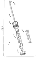
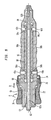
- Figure 1 is a perspective view of a compression instrument in accordance with an embodiment of the present invention.
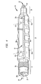
- Figure 2 is a top view of the compression instrument shown in Figure 1.
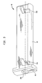
- Figure 3 is an exploded perspective view of the compression instrument shown in Figure 1.
- Figure 4 is a perspective view of a handle portion of the compression instrument shown in Figure 1.
- Figure 5 is a perspective view of a sledge portion of the compression instrument shown in Figure 1.
- Figure 6 is a perspective view of a sleeve portion of the compression instrument shown in Figure 1.
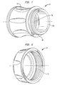
- Figure 7 is a perspective view of a knob portion of the compression instrument shown in Figure 1.
- Figure 8 is a perspective view of a nut portion of the compression instrument shown in Figure I.
- Figure 9 is a cross sectional side view of the compression instrument shown in Figure 1.
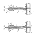
- FIGS 10a and 10b are illustrations depicting use of the compression instrument shown in Figure 1.
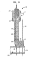
- Figure 11 is an illustration depicting use of a compression instrument according to a second embodiment of the present invention.
- compression instrument 10 is preferably usable in conjunction with many different types of bone plates or other such devices, including but not limited to, the bone plate assembly disclosed in commonly owned U.S. Patent Application published as US 2005/0143742 A1 , the disclosure of which is hereby incorporated by reference herein.
- compression instrument 10 of the present invention may be easily modified in order to be utilized in conjunction with many different bone plates. This will be discussed further below.
- compression instrument 10 may be an elongate structure having a proximal end 12 and a distal end 14.
- Compression instrument 10 is preferably sized and configured so as to allow a surgeon or other medical professional to grip and manipulate the instrument.
- compression instrument 10 may also be sized so as to allow its insertion into an incision or other opening in the body, as will be more completely discussed below in the discussion relating to the method of utilizing the present invention.
- compression instrument 10 may include a handle 16, a sledge portion 18, a K-wire sleeve 20, a knob 22 and a nut 24. These elements are each more particularly shown in Figures 4-8, respectively. Preferably, each of the elements may be interconnected with each other so as to form a single contained unit. However, it is to be understood that compression instrument 10 may include fewer or more elements in its fully constructed form. For example, as shown in Figure 3, compression instrument 10 may further include a spring assembly 26, which prevents sleeve 20 from falling out of a fully constructed instrument 10. This will be more fully discussed below, as will each of the individual elements of compression instrument 10.
- handle 16 is more particularly depicted apart from the other elements of compression instrument 10. As shown in that Figure, as well as in those figures which depict a fully constructed compression instrument 10, handle 16 may provide the majority of the structure included in instrument 10, as well as its elongate nature. In fact, handle 16 essentially extends between the aforementioned proximal and distal ends 12 and 14, and as such, these ends are shown in Figure 4. Handle 16 is preferably a tubular structure and may include three distinct sections, a distal section 30, a gripping section 32, and a tip section 34.
- Distal section 30 preferably has a threaded portion 36 for cooperating with knob 22 (this cooperation is best shown in Figure 9) and a rectangular opening 37 for capturing a portion of sleeve 20 (this cooperation is best shown in Figures 10a and 10b). Additionally, a first part 28a of a channel 28 extends through distal section 30.
- Gripping section 32 is essentially a larger and/or raised section, with respect to sections 30 and 34.
- gripping section 32 may include opposed undulating surfaces 38a and 38b for improved gripping, and a cut out section 40 with protrusions 42a, 42b, 42c and 42d extending therein, for receiving and cooperating with sledge 18.
- tip section 34 is preferably circular in cross section, and may include a proximal-most tip 44 for engaging a like sized hole on a plate.
- the tip section 34 includes a third part 28c of channel 28 extending therethrough.
- sledge portion 18 is preferably a unitary body having a first body portion 46 and a second body portion 48, wherein each of the first and second body portions may have a substantially rectangular cross-sectional shape. Additionally, first body 46 is preferably wider than second body 48, so that a portion of it extends beyond the remainder of sledge 18 along at least one direction. This width or size difference allows for cooperation with the other elements of instrument 10 during operation, as will be more fully discussed below. Second body 48 preferably includes four grooves or slots 50a, 50b, 50c and 50d, which may be angled and/or include angled sections that are adapted to mate with protrusions 42a, 42b, 42c and 42d of handle 16. Finally, sledge portion 18 may include a second part 28b of channel 28 extending therethrough.
- channel 28 includes first part or section 28a formed through distal section 30 of handle 16, second part of section 28b formed through sledge 18, and third part or section 28c formed through tip section 34 of handle 16. As a result, a continuous channel 28 may be formed in the fully assembled instrument 10.
- Figure 6 depicts sleeve 20, which is preferably adapted to fit over a K-wire or other elongate element which, in turn, may be adapted to be embedded in a bony body or the like.
- Sleeve 20 is also preferably a unitary substantially tubular body sized and configured to fit within channel 28 formed in handle 16 and sledge portion 18.
- sleeve 20 may be sized and configured to fit within channel 28, such that there may be a predetermined amount of clearance between the sleeve and the first and third parts 28a and 28c, but substantially no clearance between the sleeve and the second part 28b.
- sleeve 20 may be sized so as to have a diameter which is somewhat smaller than that of the first and third parts of channel 28, and substantially the same as that of part 28b.
- sleeve 20 may include a shoulder portion 52 for insertion into the above discussed rectangular opening 37 of handle 16.
- the rectangular opening 37 may be sized so as to be larger than shoulder portion 52, so as to provide the same or a different amount of clearance there between as compared to the clearance between sleeve 20 and parts 28a and 28c of channel 28.
- the aforementioned spring assembly 26 may be inserted into an opening 54 on shoulder portion 52 so as to prevent sleeve 20 from falling out of a fully constructed instrument 10. In operation, spring assembly 26 may exert a force upon a portion of rectangular opening 37 to prevent the inadvertent movement or removal of sleeve 20 therefrom.
- the remainder of sleeve 20 may include like sized tubular portions 56 and 58, and a smaller diameter, stepped down tubular portion 60.
- a sleeve channel 62 (best shown in the cross sectional view of Figure 9) runs through sleeve 20. As shown in Figure 9, this channel may include differently sized sections 62a and 62b, or alternatively, may be one size.
- sleeve channel 62 is sized to fit a K-wire or the like therein. However, channel 62 may also be sized so as to allow insertion of a rod, nail, screw or the like therein.
- Knob 22 may be a tubular structure having a gripping surface 64 for allowing easy gripping and rotating by a surgeon or operator. Knob 22 is preferably sized and configured to fit over distal section 30 of handle 16. More specifically, knob 22 may include an internal threaded surface 66 for engaging threaded surface 36 of handle 16. Additionally, knob 22 may also include an external threaded surface 68 for engaging nut 24. Nut 24 may be a tubular structure with an internal threaded surface 70 for engaging the aforementioned external threaded surface 68 of knob 22. Essentially, nut 24 allows the easy assembly and disassembly of instrument 10.
- instrument 10 may vary in their particular construction, including in their size and configuration.
- sleeve 20 may be sized differently in order to slide over different elongate elements inserted into the bone.
- various elements of instrument 10 may be constructed of many different types of materials.
- the components of instrument 10 may be constructed of bio-compatible materials suitable for insertion into the body of a patient, such as stainless steel or polymer materials. Titanium, aluminum and fiber-reinforced plastics may also be utilized.
- certain elements may be constructed of one type of certain material, while other elements may be constructed from a second and different type of material.
- handle 16 may be constructed of a polymeric material for easy manufacturing, while sleeve 20 may be constructed of stainless steel to insure acceptable use with stainless steel elongate elements inserted in the bone.
- sledge 18 may be inserted into cut out section 40 of handle 16, such that protrusions 42a, 42b, 42c and 42d extend into grooves 50a, 50b, 50c and 50d.
- sleeve 20 may be slid into and through all three parts 28a, 28b and 28c of channel 28, and shoulder portion 52 of sleeve 20 may be inserted into rectangular opening 37 of handle 16_
- spring assembly 26 may also be engaged with rectangular opening 37, so as to prevent the inadvertent removal or movement of sleeve 20 from handle 16.
- knob 22 may be slid over distal section 30 of handle 16, and its internal threaded surface 66 can be threadably engaged with external threaded portion 36 of distal section 30.
- an end face 68a of surface 68 of knob 22 may abut rectangular body 46 of sledge 18.
- any translational motion of knob 22, in a direction depicted by arrow B ( Figures 9-10b), may be imparted to sledge 18.
- nut 24 is slid over tip section 34 and gripping section 32 of handle 16, and threadably engaged with knob 22. That is, internal threaded surface 70 of nut 24 may engage external threaded surface 68 of knob 22.
- sledge 18 may be clamped between end face 68a of knob 22 and nut 24, so that translational motion of knob 22 and nut 24 in a direction opposite to that depicted by arrow B ( Figures 9-10b) will move sledge 18 in the same direction.
- nut 24 may not contact any other component or portion of any other component of instrument 10. Therefore, knob 22 may be free to rotate and translate or move at least partially along handle 16. This operation will be discussed more fully below. Nonetheless, with nut 24 in position, the various components of instrument 10 may be essentially locked into their assembled position.
- the final interconnection or assembly of the elements of compression instrument 10 is clearly shown in the cross sectional view of Figure 9 and in the partial cross sectional views of Figures 10a and lob.
- knob 22 In operation, clockwise rotation of knob 22 (depicted by arrow A in Figures 9-10b) causes movement along the longitudinal axis of instrument 10 in a direction depicted by arrow B ( Figures 9-10b) of both knob 22 and nut 24. As a portion of knob 22 abuts a portion of sledge 18, this longitudinal movement of knob 22 may cause similar longitudinal movement of sledge 1.8, and may also cause angled grooves 50a, 50b, 50c, and 50d to ride along protrusions 42a, 42b, 42c, and 42d, thereby resulting in translational movement of sledge 18 from one side of open cut out section 40 to the other.
- compression instrument 10 In a surgical procedure, the aforementioned transformation of rotational movement to translational movement, provided by compression instrument 10 is utilized to aid a surgeon in resetting or compressing a bone fracture.
- compression instrument 10 may be utilized with many different bone plates or other type of devices, including bone plate 80 depicted in Figures 10a and lob.
- bone plate 80 includes at least two screw holes 82 and 84 for allowing mounting to a bone 100, as well as a hole 86 for allowing insertion of tip 44 of compression instrument 10 therein. It is noted that these holes may be similarly sized, or may have different sizes or diameters.
- certain embodiment bone plates may have oblong holes, slots, threaded holes (e.g.
- bone plate 80 may be placed through an incision in the skin of the patient and onto bone 100 such that it spans across bone fragments 102 and 104 caused by fracture 106. Thereafter, a first screw or other type of fastener means may be inserted into hole 84 such that only that side of bone plate 80 is fixed to bone 100. As a result, only fragment 102 may move relative to plate 80.
- tip 44 of compression instrument 10 may be inserted through the incision and into hole 86.
- knob 22 may be turned as far as possible in a counter-clockwise direction.
- sledge 18 may be disposed as far to one side as possible.
- instrument 10 may be orientated or positioned within hole 86 such that sledge 18 is set as far away from fracture 106 as possible, so that any movement of sledge 18 would compress or close the fracture, as illustrated in Figures 10a and 10b.
- a K-wire 108 or the like may be inserted through the cannulated components of the instrument 10 and into fragment 102 of bone 100, as shown in Figure 10a.
- such position of instrument 10, and more particularly sledge 18 and sleeve 20, causes K-wire 108 to be situated to one side of hole 86 (which is the side of hole 86 further away from fracture 106).
- the K-wire 108 may be inserted bicortical.
- the next step in the surgical procedure that is, the rotation of knob 22 may be performed. It is noted that handle 16 may be held during this rotation such that the orientation of instrument 10, as shown in Figures 10a and 10b, is retained. As discussed above, rotation of knob 22 may cause translational movement of sledge 18 and sleeve 20. Therefore, performing the knob rotational step may cause these components, as well as Kwire 108, to be shifted to the position depicted in Figure 10b.
- fragment 102 may also move along with K-wire 108, thereby compressing fracture 1.06 and returning bone 100 to a pre-fracture state.
- a second screw or other type of fastener means may be inserted into hole 82 such that bone plate 80 is fixed to both fragments of bone 100, and fragments 102 and 104 can no longer move with respect to one another.
- instrument 10 and K-wire 108 may be removed.
- the hole formed in bone 100 by K-wire 108 may be bored up and/or another screw may be placed into and through hole 86.
- fragments 102 and 104 may remain in their final position ( Figure 10b) and recalcify to form one solid bone.
- the above described surgical procedure may include additional and/or different steps.
- the K-wire instead of inserting K-wire 108 after insertion of instrument 10 into hole 86, the K-wire may be inserted into bone 100 before the instrument 10 is inserted into hole 86.
- the instrument 10 may be inserted over the K-wire and into hole 86.
- other types of elements or structures may be inserted into the bone (e.g., drills, pins, bolts, nails, taps, threaded pins etc.).
- instrument 10 may be sized differently depending upon the bone fixation structure to be utilized.
- instrument 10 may be utilized to displace fragments, as opposed to compressing same.
- surgeon or other medical professional may position instrument 10 and any elongate element (e.g., K-wire 108) so that rotation of knob 22 causes one of the bone fragments to move apart from the other.
- any elongate element e.g., K-wire 108
- rotation of knob 22 causes one of the bone fragments to move apart from the other.
- the direction of compression/displacement may be adjusted by differently orienting instrument 10 and its various components. While Figures 10a and lob depict a simple straight fracture of an elongate bone, many fractures are not that simple. For such non-simple fractures, a surgeon or other medical professional may need to move bone fragments in several directions during the bone resetting process. In such circumstances, the orientation of instrument 10 may be changed accordingly.
- a bone plate may be attached to both fragments where compression/displacement is to occur, prior to such compression/displacement.
- a bone plate may be provided having an elongate slot on the side of the fracture line which includes the bone fragment to be moved.
- the bone plate may be attached to the moveable fragment with a fixation means (such as a screw or other type of fastener) through this slot.
- fixation means or screw may not be fully tightened or secured at this time.
- the instrument 10 would be operated to cause the fragment to move and the fixation means to ride along the slot.
- the fixation means or screw may be tightened to permanently affix the bone plate to the bone.
- another fixation means may be inserted through the plate and into the bone.
- instrument 10 may be used in conjunction with one or more bone plates to reset a bone with more than one fracture.
- a second fracture may be located on either side of fracture 106.
- instrument 10 may be moved to another hole situated in a position suitable for compressing the second fracture. Afterwards, a surgeon or other medical professional would simply re-perform the above noted steps to compress and fix the second fracture. This procedure may be done over and over again depending upon the overall number or type of fractures.
- the bone plate may be adapted or configured to be easily drillable so as to provide a number of holes each of a desired size and at a desired location which would be suitable to perform the above noted steps, Such would be completely understood by those of ordinary skill in the art.
- instrument 10 may be configured differently from that described above.
- sleeve 20 may be omitted and sledge 18 may be modified to accommodate the K-wire.
- knob 22 may be designed so that a force different than that of rotation could be applied thereto in order to create the translational movement to sledge 18.
- Figure 11 depicts a second embodiment instrument 200.
- instrument 200 may include many like elements, although designated with reference numerals within the 200-series of numbers.
- instrument 200 may include a handle 216, a sledge portion 218, a K-wire sleeve 220, a knob 222 and a nut 224. It is noted that these elements preferably operate in a similar fashion to that of instrument 10, so that instrument 200 can also perform a similar function.
- instrument 200 includes a lateral portion 225 having a hole 227 formed therethrough for engaging a second elongate element.
- clockwise rotation of knob 222 (depicted by arrow A' in Figure 11) preferably ultimately causes sleeve 220 to move towards or away from lateral portion 225 and hole 227.
- a surgeon may simply place instrument 200 adjacent bone 100, so that sleeve 218 rests over fragment 102 and hole 227 rests over fragment 104. Thereafter, the surgeon may utilize the tubes of sleeve 218 and hole 227 to guide the insertion of K-wires (108 and 109, respectively) into bone fragments 102 and 104, It is noted that other elongate elements, such as those discussed above, may be utilized. In addition, it is noted that such elongate elements may be inserted prior to placing instrument 200 adjacent bone 100.
Abstract
Description
- The present invention relates to the field of bone fracture repair, and more particularly, to a compression instrument for use in conjunction with a bone plate.
- For many years, bone plates and other fixation means have been widely utilized by doctors and surgeons for repairing fractures formed in bones. Such fractures typically result in otherwise unitary bone structures being split into two or more fragments, with many of these bone fractures resulting in two separate fragments. Essentially, it has been the general practice to reset the different bone fragments to their original position, place a bone plate across the fragments, and affix the plate to each of the fragments through the use of screws or other fixation means. This allows the different fragments to reattach to one another through recalcification so as to permit the fractured pieces to be reformed into the original bone structure. During this process, the affixed bone plate preferably ensures that the fragments remain in their original position, and provides a certain level of support to the bone structure.
- Although the above method of rejoining bone fragments caused by fractures has been widely utilized for many years, with overwhelmingly positive results, it is not free from any and all drawbacks. For example, while a simplified fracture repair method is basically described above, many fractures are far from simple. Often times, fractures of bones, such as long bones, are accompanied by other injuries to the body that make it difficult to reset or compress the different bone fragments to their original position. Thus, doctors or surgeons often struggle with the initial resetting of the different fragments of a fractured bone.
- Therefore, there exists a need for a compression instrument for use in conjunction with a bone plate or other such device that aids in the resetting or compressing of fractured bone fragments.
- A first aspect of the present invention is a method of moving a first bone fragment with respect to a second bone fragment. The method according to this aspect may include the steps of placing a bone plate adjacent and across the first and second bone fragments, affixing a first side of the bone plate to the first bone fragment, positioning an instrument in a hole formed in the bone plate and arranging an elongate element through a cannulated opening in said instrument and into the second bone fragment, causing a first portion of the instrument to move in a first direction to move a second portion of the instrument in a second direction which is different than said first direction, the movement of the first portion causing the second bone fragment to move with respect to the first bone fragment, and affixing a second side of the bone plate to the second bone fragment. Said bone plate may include at least three holes formed therein. Said sleeve may be cannulated for engaging said elongate element, and movement of said sleeve may cause translation of said elongate bone element. The method may include utilizing fixation means selected from the group consisting of screws, nails, bolts and staples. It is noted that the elongate element may be selected from the group consisting of K-wires, drills, pins, screws, nails and bolts. The method may be performed to move the first and second bone fragments towards or away from one another. In certain embodiments, the instrument may include a handle, a sledge, a sleeve and a knob. In these embodiments, rotation of the knob may move the sledge and sleeve in a direction perpendicular to a longitudinal axis of the handle.
- Another aspect of the present invention is a bone compression/displacement instrument. In certain embodiments, the instrument includes a handle having a longitudinal axis, a sledge inserted into a portion of the handle and a knob connected to the handle, the sledge being movable with respect to the handle. Movement of the knob may cause movement of the sledge with respect to the handle. This movement may be in a direction perpendicular to the longitudinal axis of the handle. The instrument may also include a sleeve inserted through the handle and the sledge. The handle may include a cut out section for receiving the sledge and first and third parts of a channel for receiving the sleeve. In addition, the sledge may include a second part of the channel for receiving the sleeve. The sleeve may be sized to move within the first and third parts of the channel. The sleeve may also be cannulated for receiving an elongate element therethrough. In other embodiments, the knob may be threadably connected to the handle and the instrument may include a nut threadably connected to the knob. The sledge may also include at least one groove for cooperating with at least one protrusion of the handle. Rotation of the knob may cause translation of the sledge in a direction perpendicular to the longitudinal axis of the handle. Finally, the handle may further include a tip for insertion into a hole formed through a bone plate.
- Yet another aspect of the present invention is a fracture repair kit. In accordance with certain embodiments of this third aspect, the kit includes at least one bone plate, at least one elongate element and at least one instrument each having a first portion adapted to cooperate with the bone plate, a second portion adapted to move with respect to the first portion, and a third portion adapted to cause movement of the second portion with respect to the first portion. The elongate element may be capable of being arranged with the instrument and movement of the second portion of the instrument may be capable of causing the elongate element to move with respect to the first portion of the instrument.
- A more complete appreciation of the subject matter of the present invention and the various advantages thereof can be realized by reference to the following detailed description in which reference is made to the accompanying drawings in which:
- Figure 1 is a perspective view of a compression instrument in accordance with an embodiment of the present invention.
- Figure 2 is a top view of the compression instrument shown in Figure 1.
- Figure 3 is an exploded perspective view of the compression instrument shown in Figure 1.
- Figure 4 is a perspective view of a handle portion of the compression instrument shown in Figure 1.
- Figure 5 is a perspective view of a sledge portion of the compression instrument shown in Figure 1.
- Figure 6 is a perspective view of a sleeve portion of the compression instrument shown in Figure 1.
- Figure 7 is a perspective view of a knob portion of the compression instrument shown in Figure 1.
- Figure 8 is a perspective view of a nut portion of the compression instrument shown in Figure I.
- Figure 9 is a cross sectional side view of the compression instrument shown in Figure 1.
- Figures 10a and 10b are illustrations depicting use of the compression instrument shown in Figure 1.
- Figure 11 is an illustration depicting use of a compression instrument according to a second embodiment of the present invention.
- Referring to the drawings, wherein like reference numerals refer to like elements, there is shown in Figure 1, a compression instrument designated generally by
reference numeral 10.Compression instrument 10 is preferably usable in conjunction with many different types of bone plates or other such devices, including but not limited to, the bone plate assembly disclosed in commonly owned U.S. Patent Application published asUS 2005/0143742 A1 , the disclosure of which is hereby incorporated by reference herein. However, as would be apparent to those of ordinary skill in the art,compression instrument 10 of the present invention may be easily modified in order to be utilized in conjunction with many different bone plates. This will be discussed further below. As best shown in Figures 1 and 2,compression instrument 10 may be an elongate structure having aproximal end 12 and adistal end 14.Compression instrument 10 is preferably sized and configured so as to allow a surgeon or other medical professional to grip and manipulate the instrument. In addition,compression instrument 10 may also be sized so as to allow its insertion into an incision or other opening in the body, as will be more completely discussed below in the discussion relating to the method of utilizing the present invention. - As best shown in the exploded view of Figure 3,
compression instrument 10 may include ahandle 16, asledge portion 18, a K-wire sleeve 20, aknob 22 and anut 24. These elements are each more particularly shown in Figures 4-8, respectively. Preferably, each of the elements may be interconnected with each other so as to form a single contained unit. However, it is to be understood thatcompression instrument 10 may include fewer or more elements in its fully constructed form. For example, as shown in Figure 3,compression instrument 10 may further include aspring assembly 26, which preventssleeve 20 from falling out of a fully constructedinstrument 10. This will be more fully discussed below, as will each of the individual elements ofcompression instrument 10. - Referring to Figure 4, handle 16 is more particularly depicted apart from the other elements of
compression instrument 10. As shown in that Figure, as well as in those figures which depict a fully constructedcompression instrument 10, handle 16 may provide the majority of the structure included ininstrument 10, as well as its elongate nature. In fact, handle 16 essentially extends between the aforementioned proximal anddistal ends Handle 16 is preferably a tubular structure and may include three distinct sections, adistal section 30, a grippingsection 32, and atip section 34.Distal section 30 preferably has a threadedportion 36 for cooperating with knob 22 (this cooperation is best shown in Figure 9) and arectangular opening 37 for capturing a portion of sleeve 20 (this cooperation is best shown in Figures 10a and 10b). Additionally, afirst part 28a of a channel 28 extends throughdistal section 30. Grippingsection 32 is essentially a larger and/or raised section, with respect tosections section 32 may include opposed undulatingsurfaces section 40 withprotrusions sledge 18. Finally,tip section 34 is preferably circular in cross section, and may include aproximal-most tip 44 for engaging a like sized hole on a plate. In addition, thetip section 34 includes athird part 28c of channel 28 extending therethrough. - As shown in Figure 5,
sledge portion 18 is preferably a unitary body having afirst body portion 46 and asecond body portion 48, wherein each of the first and second body portions may have a substantially rectangular cross-sectional shape. Additionally,first body 46 is preferably wider thansecond body 48, so that a portion of it extends beyond the remainder ofsledge 18 along at least one direction. This width or size difference allows for cooperation with the other elements ofinstrument 10 during operation, as will be more fully discussed below.Second body 48 preferably includes four grooves orslots protrusions handle 16. Finally,sledge portion 18 may include asecond part 28b of channel 28 extending therethrough. - Thus, channel 28 includes first part or
section 28a formed throughdistal section 30 ofhandle 16, second part ofsection 28b formed throughsledge 18, and third part orsection 28c formed throughtip section 34 ofhandle 16. As a result, a continuous channel 28 may be formed in the fully assembledinstrument 10. - Figure 6 depicts
sleeve 20, which is preferably adapted to fit over a K-wire or other elongate element which, in turn, may be adapted to be embedded in a bony body or the like.Sleeve 20 is also preferably a unitary substantially tubular body sized and configured to fit within channel 28 formed inhandle 16 andsledge portion 18. Furthermore,sleeve 20 may be sized and configured to fit within channel 28, such that there may be a predetermined amount of clearance between the sleeve and the first andthird parts second part 28b. Thus,sleeve 20 may be sized so as to have a diameter which is somewhat smaller than that of the first and third parts of channel 28, and substantially the same as that ofpart 28b. - As shown in Figure 6,
sleeve 20 may include ashoulder portion 52 for insertion into the above discussedrectangular opening 37 ofhandle 16. Therectangular opening 37 may be sized so as to be larger thanshoulder portion 52, so as to provide the same or a different amount of clearance there between as compared to the clearance betweensleeve 20 andparts aforementioned spring assembly 26 may be inserted into anopening 54 onshoulder portion 52 so as to preventsleeve 20 from falling out of a fully constructedinstrument 10. In operation,spring assembly 26 may exert a force upon a portion ofrectangular opening 37 to prevent the inadvertent movement or removal ofsleeve 20 therefrom. The remainder ofsleeve 20 may include like sizedtubular portions tubular portion 60. A sleeve channel 62 (best shown in the cross sectional view of Figure 9) runs throughsleeve 20. As shown in Figure 9, this channel may include differentlysized sections sleeve channel 62 is sized to fit a K-wire or the like therein. However,channel 62 may also be sized so as to allow insertion of a rod, nail, screw or the like therein. - Figures 7 and 8 more specifically depict
knob 22 andnut 24, respectively.Knob 22 may be a tubular structure having a grippingsurface 64 for allowing easy gripping and rotating by a surgeon or operator.Knob 22 is preferably sized and configured to fit overdistal section 30 ofhandle 16. More specifically,knob 22 may include an internal threadedsurface 66 for engaging threadedsurface 36 ofhandle 16. Additionally,knob 22 may also include an external threadedsurface 68 for engagingnut 24.Nut 24 may be a tubular structure with an internal threadedsurface 70 for engaging the aforementioned external threadedsurface 68 ofknob 22. Essentially,nut 24 allows the easy assembly and disassembly ofinstrument 10. - It is noted that the above elements of
instrument 10 may vary in their particular construction, including in their size and configuration. For example,sleeve 20 may be sized differently in order to slide over different elongate elements inserted into the bone. In addition, it is noted that the various elements ofinstrument 10 may be constructed of many different types of materials. For example, the components ofinstrument 10 may be constructed of bio-compatible materials suitable for insertion into the body of a patient, such as stainless steel or polymer materials. Titanium, aluminum and fiber-reinforced plastics may also be utilized. However, it is also noted that certain elements may be constructed of one type of certain material, while other elements may be constructed from a second and different type of material. For example, handle 16 may be constructed of a polymeric material for easy manufacturing, whilesleeve 20 may be constructed of stainless steel to insure acceptable use with stainless steel elongate elements inserted in the bone. - A method of assembly of
compression instrument 10 will now be described. However, it is to be understood that different methods of assembly may be undertaken, including assembling of parts in different orders, in different fashions, etc. Initially,sledge 18 may be inserted into cut outsection 40 ofhandle 16, such thatprotrusions grooves sleeve 20 may be slid into and through all threeparts shoulder portion 52 ofsleeve 20 may be inserted intorectangular opening 37 of handle 16_ As mentioned above,spring assembly 26 may also be engaged withrectangular opening 37, so as to prevent the inadvertent removal or movement ofsleeve 20 fromhandle 16. As such,sleeve 20 is held in place. Next,knob 22 may be slid overdistal section 30 ofhandle 16, and its internal threadedsurface 66 can be threadably engaged with external threadedportion 36 ofdistal section 30. Onceknob 22 is properly arranged onhandle 16, it is noted that anend face 68a ofsurface 68 ofknob 22 may abutrectangular body 46 ofsledge 18. Thus, any translational motion ofknob 22, in a direction depicted by arrow B (Figures 9-10b), may be imparted to sledge 18. Finally,nut 24 is slid overtip section 34 andgripping section 32 ofhandle 16, and threadably engaged withknob 22. That is, internal threadedsurface 70 ofnut 24 may engage external threadedsurface 68 ofknob 22. In addition,rectangular body 46 ofsledge 18 may be clamped betweenend face 68a ofknob 22 andnut 24, so that translational motion ofknob 22 andnut 24 in a direction opposite to that depicted by arrow B (Figures 9-10b) will movesledge 18 in the same direction. It should be noted thatnut 24 may not contact any other component or portion of any other component ofinstrument 10. Therefore,knob 22 may be free to rotate and translate or move at least partially alonghandle 16. This operation will be discussed more fully below. Nonetheless, withnut 24 in position, the various components ofinstrument 10 may be essentially locked into their assembled position. The final interconnection or assembly of the elements ofcompression instrument 10 is clearly shown in the cross sectional view of Figure 9 and in the partial cross sectional views of Figures 10a and lob. - In operation, clockwise rotation of knob 22 (depicted by arrow A in Figures 9-10b) causes movement along the longitudinal axis of
instrument 10 in a direction depicted by arrow B (Figures 9-10b) of bothknob 22 andnut 24. As a portion ofknob 22 abuts a portion ofsledge 18, this longitudinal movement ofknob 22 may cause similar longitudinal movement of sledge 1.8, and may also causeangled grooves protrusions sledge 18 from one side of open cut outsection 40 to the other. In the figures, this translational movement is best described as into and out of the paper in Figure 9, and between left and right as shown in Figures 10a and 10b (denoted by arrow C in Figures 10a and 10b). Sincesleeve 20 may be tightly disposed withinchannel part 28b ofsledge 18, and free to move somewhat withinchannel parts sleeve 20 may move along withsledge 18. Thus, rotational movement ofknob 22 ultimately may cause translational movement ofsleeve 20, as well as any elongate structure contained withinsleeve channel 62. This will be further described below. - In a surgical procedure, the aforementioned transformation of rotational movement to translational movement, provided by
compression instrument 10 is utilized to aid a surgeon in resetting or compressing a bone fracture. As mentioned above,compression instrument 10 may be utilized with many different bone plates or other type of devices, includingbone plate 80 depicted in Figures 10a and lob. In the embodiment shown in Figures 10a and lob,bone plate 80 includes at least twoscrew holes bone 100, as well as ahole 86 for allowing insertion oftip 44 ofcompression instrument 10 therein. It is noted that these holes may be similarly sized, or may have different sizes or diameters. For example, certain embodiment bone plates may have oblong holes, slots, threaded holes (e.g. for monoaxial screws), or the like. In addition, it is noted that an attachment outside of the plate is another possibility. As shown in Figure 10a,bone plate 80 may be placed through an incision in the skin of the patient and ontobone 100 such that it spans acrossbone fragments fracture 106. Thereafter, a first screw or other type of fastener means may be inserted intohole 84 such that only that side ofbone plate 80 is fixed tobone 100. As a result, only fragment 102 may move relative toplate 80. - Once one side of
bone plate 80 is affixed tobone 100 as described above,tip 44 ofcompression instrument 10 may be inserted through the incision and intohole 86. Upon or prior to such insertion,knob 22 may be turned as far as possible in a counter-clockwise direction. As such,sledge 18 may be disposed as far to one side as possible. Additionally,instrument 10 may be orientated or positioned withinhole 86 such thatsledge 18 is set as far away fromfracture 106 as possible, so that any movement ofsledge 18 would compress or close the fracture, as illustrated in Figures 10a and 10b. Withinstrument 10 in this position, a K-wire 108 or the like may be inserted through the cannulated components of theinstrument 10 and intofragment 102 ofbone 100, as shown in Figure 10a. As shown therein, such position ofinstrument 10, and more particularlysledge 18 andsleeve 20, causes K-wire 108 to be situated to one side of hole 86 (which is the side ofhole 86 further away from fracture 106). The K-wire 108 may be inserted bicortical. - After
instrument 10 has been inserted intohole 86 ofbone plate 80 and K-wire 108 has been inserted throughinstrument 10 and intobone fragment 102, as previously described, the next step in the surgical procedure, that is, the rotation ofknob 22 may be performed. It is noted that handle 16 may be held during this rotation such that the orientation ofinstrument 10, as shown in Figures 10a and 10b, is retained. As discussed above, rotation ofknob 22 may cause translational movement ofsledge 18 andsleeve 20. Therefore, performing the knob rotational step may cause these components, as well asKwire 108, to be shifted to the position depicted in Figure 10b. As a result,fragment 102 may also move along with K-wire 108, thereby compressing fracture 1.06 and returningbone 100 to a pre-fracture state. At this time, a second screw or other type of fastener means may be inserted intohole 82 such thatbone plate 80 is fixed to both fragments ofbone 100, and fragments 102 and 104 can no longer move with respect to one another. Finally,instrument 10 and K-wire 108 may be removed. The hole formed inbone 100 by K-wire 108 may be bored up and/or another screw may be placed into and throughhole 86. As a result of this surgical procedure, fragments 102 and 104 may remain in their final position (Figure 10b) and recalcify to form one solid bone. - It is to be understood that the above described surgical procedure may include additional and/or different steps. For example, instead of inserting K-
wire 108 after insertion ofinstrument 10 intohole 86, the K-wire may be inserted intobone 100 before theinstrument 10 is inserted intohole 86. In this example, theinstrument 10 may be inserted over the K-wire and intohole 86. As another example, rather than implanting a K-wire 108 intobone 100, other types of elements or structures may be inserted into the bone (e.g., drills, pins, bolts, nails, taps, threaded pins etc.). Clearly,instrument 10 may be sized differently depending upon the bone fixation structure to be utilized. In addition, it is noted thatinstrument 10 may be utilized to displace fragments, as opposed to compressing same. During such use ofinstrument 10, the surgeon or other medical professional may positioninstrument 10 and any elongate element (e.g., K-wire 108) so that rotation ofknob 22 causes one of the bone fragments to move apart from the other. This may be useful where compression fractures or the like occur in a section of a bone. Therefore, and as would be apparent to those of ordinary skill in the art, the direction of compression/displacement may be adjusted by differently orientinginstrument 10 and its various components. While Figures 10a and lob depict a simple straight fracture of an elongate bone, many fractures are not that simple. For such non-simple fractures, a surgeon or other medical professional may need to move bone fragments in several directions during the bone resetting process. In such circumstances, the orientation ofinstrument 10 may be changed accordingly. - In addition, a bone plate may be attached to both fragments where compression/displacement is to occur, prior to such compression/displacement. In this situation, a bone plate may be provided having an elongate slot on the side of the fracture line which includes the bone fragment to be moved. The bone plate may be attached to the moveable fragment with a fixation means (such as a screw or other type of fastener) through this slot. As is to be appreciated, such fixation means or screw may not be fully tightened or secured at this time. Thereafter, the
instrument 10 would be operated to cause the fragment to move and the fixation means to ride along the slot. Upon the desired positioning being achieved, the fixation means or screw may be tightened to permanently affix the bone plate to the bone. Additionally, another fixation means may be inserted through the plate and into the bone. - Furthermore, it is noted that
instrument 10 may be used in conjunction with one or more bone plates to reset a bone with more than one fracture. For example, utilizing the configuration depicted in Figures 10a and lob, a second fracture may be located on either side offracture 106. Once thefirst fracture 106 is reset in accordance with the above described process or the like,instrument 10 may be moved to another hole situated in a position suitable for compressing the second fracture. Afterwards, a surgeon or other medical professional would simply re-perform the above noted steps to compress and fix the second fracture. This procedure may be done over and over again depending upon the overall number or type of fractures. As the particulars of the fractures with respect to one another may vary tremendously, to help accommodate such variation, the bone plate may be adapted or configured to be easily drillable so as to provide a number of holes each of a desired size and at a desired location which would be suitable to perform the above noted steps, Such would be completely understood by those of ordinary skill in the art. - Additionally,
instrument 10 may be configured differently from that described above. As an example,sleeve 20 may be omitted andsledge 18 may be modified to accommodate the K-wire. In a further example, it is noted thatknob 22 may be designed so that a force different than that of rotation could be applied thereto in order to create the translational movement to sledge 18. In one envisioned embodiment, it may be possible to provide aknob 22, where a downward force to the knob would provide the desired translational movement to sledge 18. - Finally, Figure 11 depicts a
second embodiment instrument 200. Like that of the above describedinstrument 10,instrument 200 may include many like elements, although designated with reference numerals within the 200-series of numbers. For example,instrument 200 may include a handle 216, asledge portion 218, a K-wire sleeve 220, aknob 222 and anut 224. It is noted that these elements preferably operate in a similar fashion to that ofinstrument 10, so thatinstrument 200 can also perform a similar function. However, rather than cooperating with a bone plate or the like,instrument 200 includes alateral portion 225 having ahole 227 formed therethrough for engaging a second elongate element. Like that ofinstrument 10, in operation, clockwise rotation of knob 222 (depicted by arrow A' in Figure 11) preferably ultimately causessleeve 220 to move towards or away fromlateral portion 225 andhole 227. - In one surgical
procedure utilizing instrument 200, rather than utilizing a bone plate or the like, a surgeon may simply placeinstrument 200adjacent bone 100, so thatsleeve 218 rests overfragment 102 andhole 227 rests overfragment 104. Thereafter, the surgeon may utilize the tubes ofsleeve 218 andhole 227 to guide the insertion of K-wires (108 and 109, respectively) intobone fragments instrument 200adjacent bone 100. Once bothelongate elements bone 100 andinstrument 200 is engaged therewith, operation of the instrument, like that operation described in conjunction withinstrument 10, should causefragment 102 to move towardsfragment 104. Thus, the same result may be achieved withinstrument 200 as that which is achieved withinstrument 10, without the use of a bone plate or the like. - Although the invention herein has been described with reference to particular embodiments, it is to be understood that these embodiments are merely illustrative of the principles and applications of the present invention. It is therefore to be understood that numerous modifications may be made to the illustrative embodiments and that other arrangements may be devised without departing from the scope of the present invention as defined by the appended claims.
Claims (15)
- A bone compression/displacement instrument comprising:- a handle having a longitudinal axis;- a sledge arrange in a portion of said handle, said sledge being movable with respect to said handle; and a knob connected to said handle,wherein movement of said knob causes movement of said sledge with respect to said handle.
- The bone compression/displacement instrument according to claim 1, wherein movement of said sledge is in a direction perpendicular to the longitudinal axis of said handle.
- The bone compression/displacement instrument according to claim 1 or 2, further comprising a sleeve inserted through said handle and said sledge.
- The bone compression/displacement instrument according to claim 3, wherein said handle includes a cut out section for receiving said sledge and first and third parts of a channel for receiving said sleeve.
- The bone compression/displacement instrument according to claim 4, wherein said sledge includes a second part of the channel for receiving said sleeve.
- The bone compression/displacement instrument according to claim 5, wherein said sleeve is sized to move within said first and third parts of said channel.
- The bone compression/displacement instrument according to claim 3, wherein said sleeve is cannulated for receiving an elongate element therethrough.
- The bone compression/displacement instrument according to any one of claims 1 to 7, wherein said knob is threadably connected to said handle.
- The bone compression/displacement instrument according to claim 8, further comprising a nut threadably connected to said knob.
- The bone compression/displacement instrument according to any one of claims of claim 1 to 10, wherein said sledge includes at least one groove for cooperating with at least one protrusion of said handle.
- The bone compression/displacement instrument according to claim 10, wherein rotation of said knob causes translation of said sledge in a direction perpendicular to the longitudinal axis of said handle.
- The bone compression/displacement instrument according to any one of claims 1 to 11, wherein said handle further includes a tip for insertion into a hole formed through a bone plate.
- The bone compression/displacement instrument according to claim 11, further comprising a lateral portion having a hole formed therethrough.
- A fracture repair kit comprising:- at least one bone plate;- at least one elongate element; and- at least one instrument each having a first portion adapted to cooperate with said bone plate, a second portion adapted to move with respect to the first portion, and a third portion adapted to cause movement of the second portion with respect to the first portion,wherein said elongate element is capable of being arranged within said instrument and wherein movement of the second portion of said instrument is capable of causing said elongate element to move with respect to the first portion of said instrument.
- A method of moving a first bone fragment with respect to a second bone fragment, the method comprising the steps of:- placing a bone plate adjacent and across said first and second bone fragments;- affixing a first side of said bone plate to said first bone fragment;- positioning an instrument according to one of claims 1 to 13 in a hole formed in said bone plate and arranging an elongate element through a cannulated opening in said instrument and into said second bone fragment;- causing a first portion of said instrument to move in a first direction to move a second portion of said instrument in a second direction which is different than said first direction, the movement of said first portion causing said second bone fragment to move with respect to said first bone fragment; and- affixing a second side of said bone plate to said second bone fragment.
Applications Claiming Priority (1)
| Application Number | Priority Date | Filing Date | Title |
|---|---|---|---|
| US11/285,808 US7704257B2 (en) | 2005-11-23 | 2005-11-23 | Compression instrument |
Publications (2)
| Publication Number | Publication Date |
|---|---|
| EP1790302A1 true EP1790302A1 (en) | 2007-05-30 |
| EP1790302B1 EP1790302B1 (en) | 2015-11-04 |
Family
ID=37744791
Family Applications (1)
| Application Number | Title | Priority Date | Filing Date |
|---|---|---|---|
| EP06405476.0A Not-in-force EP1790302B1 (en) | 2005-11-23 | 2006-11-13 | Compression instrument |
Country Status (7)
| Country | Link |
|---|---|
| US (1) | US7704257B2 (en) |
| EP (1) | EP1790302B1 (en) |
| JP (1) | JP4926668B2 (en) |
| CN (1) | CN101002695B (en) |
| AU (1) | AU2006236054B2 (en) |
| CA (1) | CA2568614C (en) |
| ES (1) | ES2556589T3 (en) |
Cited By (1)
| Publication number | Priority date | Publication date | Assignee | Title |
|---|---|---|---|---|
| EP2397083A1 (en) * | 2007-11-02 | 2011-12-21 | DePuy Products, Inc. | Elbow fracture fixation system |
Families Citing this family (9)
| Publication number | Priority date | Publication date | Assignee | Title |
|---|---|---|---|---|
| DE50313414D1 (en) * | 2003-08-08 | 2011-02-24 | Synthes Gmbh | LOCKING DEVICE |
| WO2005112800A2 (en) * | 2004-05-17 | 2005-12-01 | Tiax Llc | Intraosseous infusion device |
| US9060748B2 (en) * | 2009-03-18 | 2015-06-23 | Smith & Nephew, Inc. | Soft tissue manipulator assembly |
| WO2011031495A2 (en) * | 2009-08-25 | 2011-03-17 | K-Comp, Llc | Bone compression system |
| US10441317B2 (en) | 2016-10-26 | 2019-10-15 | SIGN Fracture Care International | Bone fixation system and method using a clamping instrument to guide fastener placement |
| WO2018223063A1 (en) * | 2017-06-01 | 2018-12-06 | Shawn Burke | Method and system for the reduction and fixation of bone segments |
| KR102086690B1 (en) * | 2018-02-13 | 2020-03-10 | 큐렉소 주식회사 | Surgical operation apparatus for medical screw, surgical robot using thererof and surgical method for using trereof |
| CN109009393A (en) * | 2018-07-24 | 2018-12-18 | 莆田学院附属医院(莆田市第二医院) | A kind of minimal invasion reduction of the fracture device |
| US11844556B2 (en) * | 2021-12-07 | 2023-12-19 | Arthrex, Inc. | Surgical reduction tools and methods for achieving bone compression |
Citations (6)
| Publication number | Priority date | Publication date | Assignee | Title |
|---|---|---|---|---|
| CH373516A (en) | 1959-09-01 | 1963-11-30 | Maurice E Dr Med Mueller | Device for the surgical fixation of bone fragments in limbs |
| FR2210908A6 (en) * | 1972-12-15 | 1974-07-12 | Emco Sa | |
| SU594973A1 (en) * | 1975-05-11 | 1978-02-28 | Shavgulidze Tamazi Sh | Wire-tensioning device |
| WO2001030249A1 (en) | 1999-10-27 | 2001-05-03 | Synthes Ag Chur | Method and apparatus for ratcheting adjustment of bone segments |
| FR2824468A1 (en) | 2001-05-14 | 2002-11-15 | Adalbert Ibrahim Kapandji | External fixator for long bone epiphysis fractures has adjustable diaphysis and epiphysis components with fixing pins |
| US20030181912A1 (en) * | 1997-02-11 | 2003-09-25 | Michelson Gary K. | Anterior cervical plating system and bone screw |
Family Cites Families (53)
| Publication number | Priority date | Publication date | Assignee | Title |
|---|---|---|---|---|
| US1395587A (en) * | 1920-07-26 | 1921-11-01 | Mclachlan John | Cam-shaft remover |
| US1997466A (en) * | 1934-04-23 | 1935-04-09 | Harry Herschel Leiter | Surgical appliance |
| US2224480A (en) * | 1939-10-27 | 1940-12-10 | Kartarik Joseph | Centering device |
| US2301500A (en) * | 1940-05-31 | 1942-11-10 | Anderson Roger | Wire guiding device |
| US3244170A (en) * | 1962-11-23 | 1966-04-05 | Robert T Mcelvenny | Compression type bone splint |
| US3386437A (en) * | 1966-01-14 | 1968-06-04 | Richard Mfg Company | Compression device for use with a bone fracture plate |
| USRE28841E (en) * | 1966-06-22 | 1976-06-08 | Synthes A.G. | Osteosynthetic pressure plate construction |
| USRE31628E (en) * | 1966-06-22 | 1984-07-10 | Synthes Ag | Osteosynthetic pressure plate construction |
| FR1538053A (en) * | 1967-08-18 | 1968-09-07 | Osteosynthesis plate combined with its key | |
| US3540322A (en) * | 1968-08-09 | 1970-11-17 | Carl E Swanson | Drill fixtures |
| US3709219A (en) * | 1970-11-27 | 1973-01-09 | W Halloran | Bone compression device |
| US3866607A (en) * | 1973-08-09 | 1975-02-18 | Environmental Sciences Corp | Bone fracture compression device and method of usage |
| GB1571713A (en) * | 1976-04-21 | 1980-07-16 | Gil J L | Apparatus for use in the treatment of bone fractures |
| CH645264A5 (en) * | 1980-05-28 | 1984-09-28 | Straumann Inst Ag | FITTING WITH A PLATE AND SCREWS THAT FIX IT TO A BONE. |
| US4502160A (en) * | 1983-10-27 | 1985-03-05 | Dow Corning Wright | Adjustable length prosthetic joint implant |
| DE3701533A1 (en) * | 1987-01-21 | 1988-08-04 | Medi System Gmbh | OSTEOSYNTHESIS TOOLS |
| CN2036410U (en) * | 1988-07-30 | 1989-04-26 | 滁县地区第二人民医院 | External skeletal fixation device for tibia |
| FI82805C (en) * | 1988-12-23 | 1991-04-25 | Biocon Oy | EN POLYMER FIXERINGSKIVKONSTRUKTION FOER KIRURGISKT BRUK. |
| US5021056A (en) * | 1989-09-14 | 1991-06-04 | Intermedics Orthopedics, Inc. | Upper tibial osteotomy system |
| US5167665A (en) * | 1991-12-31 | 1992-12-01 | Mckinney William W | Method of attaching objects to bone |
| US5290281A (en) * | 1992-06-15 | 1994-03-01 | Medicon Eg | Surgical system |
| DE9216565U1 (en) * | 1992-12-04 | 1994-03-31 | Link Waldemar Gmbh Co | Device for connecting bone parts by means of a bone plate |
| IL105183A (en) * | 1993-03-28 | 1996-07-23 | Yehiel Gotfried | Surgical device for connection of fractured bones |
| US5364396A (en) * | 1993-03-29 | 1994-11-15 | Robinson Randolph C | Distraction method and apparatus |
| US5505733A (en) * | 1993-10-22 | 1996-04-09 | Justin; Daniel F. | Intramedullary skeletal distractor and method |
| US5788697A (en) * | 1994-02-24 | 1998-08-04 | Pioneer Laboratories, Inc. | Cable tensioning device |
| US5439465A (en) * | 1994-03-11 | 1995-08-08 | Tumibay; Delfin O. | Bone compression and distraction surgical tool |
| US5632747A (en) * | 1995-03-15 | 1997-05-27 | Osteotech, Inc. | Bone dowel cutter |
| US5634926A (en) * | 1995-04-25 | 1997-06-03 | Jobe; Richard P. | Surgical bone fixation apparatus |
| CA2158890C (en) * | 1995-09-22 | 2002-01-22 | John Runciman | Spherical washer for use with a bone screw |
| EP0770359A1 (en) * | 1995-10-05 | 1997-05-02 | Medicon e.G. Chirurgiemechaniker-Genossenschaft | Distraction device for bone segments |
| US5676667A (en) * | 1995-12-08 | 1997-10-14 | Hausman; Michael | Bone fixation apparatus and method |
| US5849012A (en) * | 1996-03-11 | 1998-12-15 | Abboudi; Shalom Y. | Surgical clamping assemblies and methods of use |
| US5976139A (en) * | 1996-07-17 | 1999-11-02 | Bramlet; Dale G. | Surgical fastener assembly |
| DE19637938A1 (en) * | 1996-09-17 | 1998-03-26 | Juergen Harms | Bone plate |
| US5810824A (en) * | 1997-02-13 | 1998-09-22 | Chan; Kwan-Ho | Surgical fastener assembly and method for bone fracture fixation |
| US5827286A (en) * | 1997-02-14 | 1998-10-27 | Incavo; Stephen J. | Incrementally adjustable tibial osteotomy fixation device and method |
| IT1298413B1 (en) * | 1997-05-21 | 2000-01-05 | Orthofix Srl | EXTERNAL MINIFIXER DEVICE FOR SMALL BONE TREATMENT |
| US5964769A (en) * | 1997-08-26 | 1999-10-12 | Spinal Concepts, Inc. | Surgical cable system and method |
| US5951557A (en) * | 1997-12-30 | 1999-09-14 | Luter; Dennis W. | Bone plate |
| CA2332557C (en) * | 1998-05-19 | 2007-04-17 | Synthes (U.S.A.) | Telescopic body for an external fixation system |
| US6200321B1 (en) * | 1998-09-10 | 2001-03-13 | Hand Innovations, Inc. | Fracture fixation system |
| DE19858889B4 (en) * | 1998-12-19 | 2008-08-07 | Wolter, Dietmar, Prof. Dr.Med. | Fixation system for bones |
| DE19859135B4 (en) * | 1998-12-21 | 2006-07-13 | Ferton Holding S.A. | Device for driving a wire pin, in particular a Kirschner wire, in bone material |
| PT1235520E (en) * | 1999-12-10 | 2004-08-31 | Synthes Ag | DEVICE FOR DISTING OR COMPRESSING BONES OR PARTS OF BONES |
| US6641583B2 (en) * | 2001-03-29 | 2003-11-04 | Endius Incorporated | Apparatus for retaining bone portions in a desired spatial relationship |
| US6709439B2 (en) * | 2001-10-30 | 2004-03-23 | Depuy Spine, Inc. | Slaphammer tool |
| US6852113B2 (en) * | 2001-12-14 | 2005-02-08 | Orthopaedic Designs, Llc | Internal osteotomy fixation device |
| US6723098B1 (en) * | 2002-03-12 | 2004-04-20 | Mrugesh K. Shah | Bone fixation plate having clip members |
| US6695846B2 (en) * | 2002-03-12 | 2004-02-24 | Spinal Innovations, Llc | Bone plate and screw retaining mechanism |
| US7195633B2 (en) * | 2004-01-08 | 2007-03-27 | Robert J. Medoff | Fracture fixation system |
| US7207995B1 (en) * | 2004-01-29 | 2007-04-24 | Biomer Manufacturing Corp. | Method and apparatus for retaining a guide wire |
| CN2691503Y (en) * | 2004-03-13 | 2005-04-13 | 王卫东 | External fixer for bone |
-
2005
- 2005-11-23 US US11/285,808 patent/US7704257B2/en not_active Expired - Fee Related
-
2006
- 2006-11-13 EP EP06405476.0A patent/EP1790302B1/en not_active Not-in-force
- 2006-11-13 ES ES06405476.0T patent/ES2556589T3/en active Active
- 2006-11-17 AU AU2006236054A patent/AU2006236054B2/en not_active Ceased
- 2006-11-21 CA CA2568614A patent/CA2568614C/en not_active Expired - Fee Related
- 2006-11-22 JP JP2006315334A patent/JP4926668B2/en active Active
- 2006-11-22 CN CN2006101449348A patent/CN101002695B/en not_active Expired - Fee Related
Patent Citations (6)
| Publication number | Priority date | Publication date | Assignee | Title |
|---|---|---|---|---|
| CH373516A (en) | 1959-09-01 | 1963-11-30 | Maurice E Dr Med Mueller | Device for the surgical fixation of bone fragments in limbs |
| FR2210908A6 (en) * | 1972-12-15 | 1974-07-12 | Emco Sa | |
| SU594973A1 (en) * | 1975-05-11 | 1978-02-28 | Shavgulidze Tamazi Sh | Wire-tensioning device |
| US20030181912A1 (en) * | 1997-02-11 | 2003-09-25 | Michelson Gary K. | Anterior cervical plating system and bone screw |
| WO2001030249A1 (en) | 1999-10-27 | 2001-05-03 | Synthes Ag Chur | Method and apparatus for ratcheting adjustment of bone segments |
| FR2824468A1 (en) | 2001-05-14 | 2002-11-15 | Adalbert Ibrahim Kapandji | External fixator for long bone epiphysis fractures has adjustable diaphysis and epiphysis components with fixing pins |
Cited By (2)
| Publication number | Priority date | Publication date | Assignee | Title |
|---|---|---|---|---|
| EP2397083A1 (en) * | 2007-11-02 | 2011-12-21 | DePuy Products, Inc. | Elbow fracture fixation system |
| US9750549B2 (en) | 2007-11-02 | 2017-09-05 | Biomet C.V. | Plate benders for bone plates |
Also Published As
| Publication number | Publication date |
|---|---|
| CA2568614C (en) | 2014-04-29 |
| AU2006236054A1 (en) | 2007-06-07 |
| US7704257B2 (en) | 2010-04-27 |
| JP4926668B2 (en) | 2012-05-09 |
| EP1790302B1 (en) | 2015-11-04 |
| US20070118146A1 (en) | 2007-05-24 |
| CA2568614A1 (en) | 2007-05-23 |
| CN101002695A (en) | 2007-07-25 |
| JP2007144166A (en) | 2007-06-14 |
| AU2006236054B2 (en) | 2012-09-13 |
| ES2556589T3 (en) | 2016-01-19 |
| CN101002695B (en) | 2011-01-05 |
Similar Documents
| Publication | Publication Date | Title |
|---|---|---|
| CA2568614C (en) | Compression instrument | |
| AU2017101794A4 (en) | Bone plates with dynamic elements | |
| US7416553B2 (en) | Drill guide and plate inserter | |
| US20170273684A1 (en) | Surgical instrument | |
| US9795428B2 (en) | Bone implantation and stabilization assembly including deployment device | |
| JP5138587B2 (en) | Adjustable locking clamp and method | |
| EP2563252B1 (en) | Bone fixation systems | |
| AU2005292286B2 (en) | Less invasive surgical system and methods | |
| CA2713982C (en) | Pelvic cable solution | |
| US7645282B2 (en) | Method and device for cutting surgical wire or cable | |
| US20090254129A1 (en) | Bone screw system and method for the fixation of bone fractures | |
| US20090254089A1 (en) | Stabilization system and method for the fixation of bone fractures | |
| US20090306718A1 (en) | Filament and cap systems and methods for the fixation of bone fractures | |
| US20100312292A1 (en) | Lagwire system and method for the fixation of bone fractures | |
| JP2011516150A (en) | Intramedullary instrument assembly and related methods | |
| JP2013540476A (en) | Spinal process grasping system and use thereof | |
| JP2019150562A (en) | Compressor/distractor | |
| US20040210232A1 (en) | Guide device and plate inserter | |
| EP1872733A1 (en) | Bone plate clamp | |
| EP1779798B1 (en) | Non-penetrating fixing device | |
| CN112074245B (en) | Improved dynamic device for orthopedic fixation devices | |
| CN112074245A (en) | Improved dynamic device for orthopedic fixation devices |
Legal Events
| Date | Code | Title | Description |
|---|---|---|---|
| PUAI | Public reference made under article 153(3) epc to a published international application that has entered the european phase |
Free format text: ORIGINAL CODE: 0009012 |
|
| AK | Designated contracting states |
Kind code of ref document: A1 Designated state(s): AT BE BG CH CY CZ DE DK EE ES FI FR GB GR HU IE IS IT LI LT LU LV MC NL PL PT RO SE SI SK TR |
|
| AX | Request for extension of the european patent |
Extension state: AL BA HR MK YU |
|
| 17P | Request for examination filed |
Effective date: 20070613 |
|
| 17Q | First examination report despatched |
Effective date: 20070718 |
|
| AKX | Designation fees paid |
Designated state(s): CH DE ES FR GB IT LI |
|
| GRAP | Despatch of communication of intention to grant a patent |
Free format text: ORIGINAL CODE: EPIDOSNIGR1 |
|
| INTG | Intention to grant announced |
Effective date: 20150309 |
|
| GRAP | Despatch of communication of intention to grant a patent |
Free format text: ORIGINAL CODE: EPIDOSNIGR1 |
|
| INTG | Intention to grant announced |
Effective date: 20150715 |
|
| GRAS | Grant fee paid |
Free format text: ORIGINAL CODE: EPIDOSNIGR3 |
|
| GRAR | Information related to intention to grant a patent recorded |
Free format text: ORIGINAL CODE: EPIDOSNIGR71 |
|
| GRAA | (expected) grant |
Free format text: ORIGINAL CODE: 0009210 |
|
| INTG | Intention to grant announced |
Effective date: 20150924 |
|
| AK | Designated contracting states |
Kind code of ref document: B1 Designated state(s): CH DE ES FR GB IT LI |
|
| REG | Reference to a national code |
Ref country code: GB Ref legal event code: FG4D |
|
| REG | Reference to a national code |
Ref country code: DE Ref legal event code: R081 Ref document number: 602006047140 Country of ref document: DE Owner name: STRYKER EUROPEAN HOLDINGS I, LLC (N.D. GES. D., US Free format text: FORMER OWNER: STRYKER TRAUMA S.A., SELZACH, CH |
|
| REG | Reference to a national code |
Ref country code: CH Ref legal event code: EP |
|
| REG | Reference to a national code |
Ref country code: CH Ref legal event code: NV Representative=s name: ISLER AND PEDRAZZINI AG, CH |
|
| REG | Reference to a national code |
Ref country code: DE Ref legal event code: R096 Ref document number: 602006047140 Country of ref document: DE |
|
| REG | Reference to a national code |
Ref country code: FR Ref legal event code: PLFP Year of fee payment: 10 |
|
| REG | Reference to a national code |
Ref country code: ES Ref legal event code: FG2A Ref document number: 2556589 Country of ref document: ES Kind code of ref document: T3 Effective date: 20160119 |
|
| REG | Reference to a national code |
Ref country code: CH Ref legal event code: PUE Owner name: STRYKER EUROPEAN HOLDINGS I, LLC, US Free format text: FORMER OWNER: STRYKER EUROPEAN HOLDINGS V, LLC, US Ref country code: CH Ref legal event code: PUE Owner name: STRYKER EUROPEAN HOLDINGS V, LLC, US Free format text: FORMER OWNER: STRYKER TRAUMA SA, CH |
|
| REG | Reference to a national code |
Ref country code: DE Ref legal event code: R081 Ref document number: 602006047140 Country of ref document: DE Owner name: STRYKER EUROPEAN OPERATIONS HOLDINGS LLC, KALA, US Free format text: FORMER OWNER: STRYKER TRAUMA SA, SELZACH, CH Ref country code: DE Ref legal event code: R081 Ref document number: 602006047140 Country of ref document: DE Owner name: STRYKER EUROPEAN OPERATIONS HOLDINGS LLC, KALA, US Free format text: FORMER OWNER: STRYKER EUROPEAN HOLDINGS V, LLC (N.D. GES. D. STAATES DELAWARE), KALAMAZOO, MICH., US Ref country code: DE Ref legal event code: R082 Ref document number: 602006047140 Country of ref document: DE Representative=s name: MAIWALD PATENTANWALTSGESELLSCHAFT MBH, DE Ref country code: DE Ref legal event code: R081 Ref document number: 602006047140 Country of ref document: DE Owner name: STRYKER EUROPEAN HOLDINGS I, LLC (N.D. GES. D., US Free format text: FORMER OWNER: STRYKER EUROPEAN HOLDINGS V, LLC (N.D. GES. D. STAATES DELAWARE), KALAMAZOO, MICH., US Ref country code: DE Ref legal event code: R081 Ref document number: 602006047140 Country of ref document: DE Owner name: STRYKER EUROPEAN HOLDINGS I, LLC (N.D. GES. D., US Free format text: FORMER OWNER: STRYKER TRAUMA SA, SELZACH, CH Ref country code: DE Ref legal event code: R082 Ref document number: 602006047140 Country of ref document: DE Representative=s name: MAIWALD PATENTANWALTS- UND RECHTSANWALTSGESELL, DE |
|
| REG | Reference to a national code |
Ref country code: DE Ref legal event code: R097 Ref document number: 602006047140 Country of ref document: DE |
|
| PLBE | No opposition filed within time limit |
Free format text: ORIGINAL CODE: 0009261 |
|
| STAA | Information on the status of an ep patent application or granted ep patent |
Free format text: STATUS: NO OPPOSITION FILED WITHIN TIME LIMIT |
|
| 26N | No opposition filed |
Effective date: 20160805 |
|
| REG | Reference to a national code |
Ref country code: FR Ref legal event code: PLFP Year of fee payment: 11 |
|
| REG | Reference to a national code |
Ref country code: FR Ref legal event code: TP Owner name: STRYKER EUROPEAN HOLDINGS I, LLC, US Effective date: 20161003 |
|
| REG | Reference to a national code |
Ref country code: GB Ref legal event code: 732E Free format text: REGISTERED BETWEEN 20161013 AND 20161019 |
|
| REG | Reference to a national code |
Ref country code: ES Ref legal event code: PC2A Owner name: STRYKER EUROPEAN HOLDINGS I, LLC Effective date: 20161111 |
|
| REG | Reference to a national code |
Ref country code: FR Ref legal event code: PLFP Year of fee payment: 12 |
|
| PGFP | Annual fee paid to national office [announced via postgrant information from national office to epo] |
Ref country code: ES Payment date: 20171201 Year of fee payment: 12 Ref country code: IT Payment date: 20171123 Year of fee payment: 12 |
|
| REG | Reference to a national code |
Ref country code: FR Ref legal event code: PLFP Year of fee payment: 13 |
|
| PG25 | Lapsed in a contracting state [announced via postgrant information from national office to epo] |
Ref country code: IT Free format text: LAPSE BECAUSE OF NON-PAYMENT OF DUE FEES Effective date: 20181113 |
|
| REG | Reference to a national code |
Ref country code: ES Ref legal event code: FD2A Effective date: 20200103 |
|
| PG25 | Lapsed in a contracting state [announced via postgrant information from national office to epo] |
Ref country code: ES Free format text: LAPSE BECAUSE OF NON-PAYMENT OF DUE FEES Effective date: 20181114 |
|
| PGFP | Annual fee paid to national office [announced via postgrant information from national office to epo] |
Ref country code: FR Payment date: 20201013 Year of fee payment: 15 Ref country code: GB Payment date: 20201104 Year of fee payment: 15 Ref country code: CH Payment date: 20201117 Year of fee payment: 15 Ref country code: DE Payment date: 20201103 Year of fee payment: 15 |
|
| REG | Reference to a national code |
Ref country code: CH Ref legal event code: PUE Owner name: STRYKER EUROPEANS OPERATIONS HOLDINGS LLC, US Free format text: FORMER OWNER: STRYKER EUROPEAN HOLDINGS I, LLC, US |
|
| REG | Reference to a national code |
Ref country code: CH Ref legal event code: PK Free format text: BERICHTIGUNG INHABER |
|
| REG | Reference to a national code |
Ref country code: DE Ref legal event code: R082 Ref document number: 602006047140 Country of ref document: DE Representative=s name: MAIWALD PATENTANWALTS- UND RECHTSANWALTSGESELL, DE Ref country code: DE Ref legal event code: R081 Ref document number: 602006047140 Country of ref document: DE Owner name: STRYKER EUROPEAN OPERATIONS HOLDINGS LLC, KALA, US Free format text: FORMER OWNER: STRYKER EUROPEAN HOLDINGS I, LLC (N.D. GES. D. STAATES DELAWARE), KALAMAZOO, MICH., US |
|
| REG | Reference to a national code |
Ref country code: GB Ref legal event code: 732E Free format text: REGISTERED BETWEEN 20210408 AND 20210414 |
|
| REG | Reference to a national code |
Ref country code: DE Ref legal event code: R119 Ref document number: 602006047140 Country of ref document: DE |
|
| REG | Reference to a national code |
Ref country code: CH Ref legal event code: PL |
|
| GBPC | Gb: european patent ceased through non-payment of renewal fee |
Effective date: 20211113 |
|
| PG25 | Lapsed in a contracting state [announced via postgrant information from national office to epo] |
Ref country code: GB Free format text: LAPSE BECAUSE OF NON-PAYMENT OF DUE FEES Effective date: 20211113 Ref country code: DE Free format text: LAPSE BECAUSE OF NON-PAYMENT OF DUE FEES Effective date: 20220601 |
|
| PG25 | Lapsed in a contracting state [announced via postgrant information from national office to epo] |
Ref country code: FR Free format text: LAPSE BECAUSE OF NON-PAYMENT OF DUE FEES Effective date: 20211130 |
|
| PG25 | Lapsed in a contracting state [announced via postgrant information from national office to epo] |
Ref country code: LI Free format text: LAPSE BECAUSE OF NON-PAYMENT OF DUE FEES Effective date: 20220701 Ref country code: CH Free format text: LAPSE BECAUSE OF NON-PAYMENT OF DUE FEES Effective date: 20220701 |