EP1801986A1 - Wireless headset for a mobile phone - Google Patents
Wireless headset for a mobile phone Download PDFInfo
- Publication number
- EP1801986A1 EP1801986A1 EP05257371A EP05257371A EP1801986A1 EP 1801986 A1 EP1801986 A1 EP 1801986A1 EP 05257371 A EP05257371 A EP 05257371A EP 05257371 A EP05257371 A EP 05257371A EP 1801986 A1 EP1801986 A1 EP 1801986A1
- Authority
- EP
- European Patent Office
- Prior art keywords
- microphone
- wireless
- headset
- wireless communications
- codec
- Prior art date
- Legal status (The legal status is an assumption and is not a legal conclusion. Google has not performed a legal analysis and makes no representation as to the accuracy of the status listed.)
- Granted
Links
- 238000004891 communication Methods 0.000 claims abstract description 28
- 230000008878 coupling Effects 0.000 claims abstract description 11
- 238000010168 coupling process Methods 0.000 claims abstract description 11
- 238000005859 coupling reaction Methods 0.000 claims abstract description 11
- 230000036039 immunity Effects 0.000 claims abstract description 4
- 229910000859 α-Fe Inorganic materials 0.000 claims description 17
- 239000003990 capacitor Substances 0.000 claims description 14
- 239000011324 bead Substances 0.000 claims description 13
- 238000000034 method Methods 0.000 claims description 6
- 210000000613 ear canal Anatomy 0.000 claims description 4
- 238000004519 manufacturing process Methods 0.000 claims 1
- 238000010586 diagram Methods 0.000 description 7
- 238000012986 modification Methods 0.000 description 3
- 230000004048 modification Effects 0.000 description 3
- 239000000758 substrate Substances 0.000 description 3
- PXHVJJICTQNCMI-UHFFFAOYSA-N Nickel Chemical compound [Ni] PXHVJJICTQNCMI-UHFFFAOYSA-N 0.000 description 2
- 230000006978 adaptation Effects 0.000 description 2
- 230000008901 benefit Effects 0.000 description 2
- 230000001413 cellular effect Effects 0.000 description 2
- 230000001939 inductive effect Effects 0.000 description 2
- HCHKCACWOHOZIP-UHFFFAOYSA-N Zinc Chemical compound [Zn] HCHKCACWOHOZIP-UHFFFAOYSA-N 0.000 description 1
- 230000003044 adaptive effect Effects 0.000 description 1
- 239000000919 ceramic Substances 0.000 description 1
- 230000009977 dual effect Effects 0.000 description 1
- 230000000694 effects Effects 0.000 description 1
- 238000005516 engineering process Methods 0.000 description 1
- UQSXHKLRYXJYBZ-UHFFFAOYSA-N iron oxide Inorganic materials [Fe]=O UQSXHKLRYXJYBZ-UHFFFAOYSA-N 0.000 description 1
- 238000002955 isolation Methods 0.000 description 1
- 239000000463 material Substances 0.000 description 1
- 238000010295 mobile communication Methods 0.000 description 1
- 229910052759 nickel Inorganic materials 0.000 description 1
- NDLPOXTZKUMGOV-UHFFFAOYSA-N oxo(oxoferriooxy)iron hydrate Chemical compound O.O=[Fe]O[Fe]=O NDLPOXTZKUMGOV-UHFFFAOYSA-N 0.000 description 1
- 230000002093 peripheral effect Effects 0.000 description 1
- 230000035699 permeability Effects 0.000 description 1
- 230000008569 process Effects 0.000 description 1
- 229910000679 solder Inorganic materials 0.000 description 1
- 230000001629 suppression Effects 0.000 description 1
- 229910052725 zinc Inorganic materials 0.000 description 1
- 239000011701 zinc Substances 0.000 description 1
Images


Classifications
-
- H—ELECTRICITY
- H04—ELECTRIC COMMUNICATION TECHNIQUE
- H04M—TELEPHONIC COMMUNICATION
- H04M1/00—Substation equipment, e.g. for use by subscribers
- H04M1/60—Substation equipment, e.g. for use by subscribers including speech amplifiers
- H04M1/6033—Substation equipment, e.g. for use by subscribers including speech amplifiers for providing handsfree use or a loudspeaker mode in telephone sets
- H04M1/6041—Portable telephones adapted for handsfree use
- H04M1/6058—Portable telephones adapted for handsfree use involving the use of a headset accessory device connected to the portable telephone
- H04M1/6066—Portable telephones adapted for handsfree use involving the use of a headset accessory device connected to the portable telephone including a wireless connection
-
- H—ELECTRICITY
- H04—ELECTRIC COMMUNICATION TECHNIQUE
- H04B—TRANSMISSION
- H04B1/00—Details of transmission systems, not covered by a single one of groups H04B3/00 - H04B13/00; Details of transmission systems not characterised by the medium used for transmission
- H04B1/38—Transceivers, i.e. devices in which transmitter and receiver form a structural unit and in which at least one part is used for functions of transmitting and receiving
- H04B1/3827—Portable transceivers
- H04B1/385—Transceivers carried on the body, e.g. in helmets
- H04B2001/3866—Transceivers carried on the body, e.g. in helmets carried on the head
Definitions
- This invention relates to wireless headsets, and more particularly, this invention relates to wireless headsets that incorporate a Bluetooth module.
- Bluetooth headsets that incorporate a Bluetooth module to enable its wireless communications are becoming more commonplace and are advantageous because Bluetooth eliminates the connection of wires associated with most consumer computer equipment and allows a collection of products to function as an intelligent whole. It also makes location connectivity seamless.
- a Bluetooth system or module typically includes a radio, a baseband controller, a link manager, a logical link control, an adaptation protocol manager, host controller interface and application program interface library.
- GSM Global System for Mobile communications
- a wireless headset has improved immunity to RF electromagnetic interference produced from wireless communication devices, for example, a cellular phone.
- a headset body is adapted to be worn by a user and includes a microphone carried by the headset body for receiving voice signals from the user and an earpiece carried by the headset body for directing voice signals into an ear canal of the user.
- RF and audio circuitry are mounted within the headset body and connected to an antenna for receiving and transmitting wireless communications signals.
- the RF and audio circuitry include a Bluetooth module operatively connected to the antenna and an audio CODEC connected to the Bluetooth module. Audio connection lines are connected between the CODEC and the earpiece and between the CODEC and the microphone.
- a filter is connected into each of the audio connection lines at the earpiece and microphone and operative for reducing the RF coupling from a wireless communications device.
- a filter is serially connected into each audio connection line and can be formed as a ferrite inductor, including a ferrite bead.
- the filter can also be formed as an LC filter serially connected into an audio connection line.
- a series connected inductor and capacitor can be connected into an audio connection line connected to the earpiece.
- the inductor could be formed as a ferrite inductor and an RF shield could surround one of at least the earpiece or microphone to aid in reducing the RF coupling from a mobile wireless communications device. This RF shield could be formed as a metallic housing.
- microphone bias lines connect the CODEC and microphone for passing microphone bias control signals between the CODEC and the microphone.
- a microphone bias filter in one non-limiting aspect, would be operative with the microphone bias lines for reducing the RF coupling from a wireless communications device.
- the microphone bias filter could be formed as a serial inductor, shunt capacitor, or ferrite bead. It can also be formed as a ground connected capacitor.
- a method aspect is also set forth.
- FIG. 1 is a perspective view of a wireless "Bluetooth" headset that can incorporate an RF filter to reduce RF coupling from a mobile wireless communications device, in accordance with one non-limiting example.
- FIG. 2 is a block diagram showing basic functional components of a wireless or Bluetooth headset that could be adapted to incorporate an RF filter to decrease unwanted audible noise, such as GSM buzz.
- FIG. 3 is a schematic circuit diagram showing a combination earpiece and filter circuit, which could be incorporated into the earpiece shown in FIG. 2.
- FIG. 4 is a schematic circuit diagram showing a combination microphone and filter circuit, which could be incorporated into the microphone shown in FIG. 2.
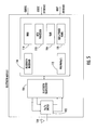
- FIG. 5 is a high-level block diagram of a Bluetooth module that could be used in the wireless headset shown in FIG. 2.
- FIG. 6 is a high-level block diagram of an audio CODEC that could be used in the wireless headset shown in FIG. 2.
- RF filters and RF shielding can be implemented and applied to a microphone circuit and speaker circuit in a wireless "Bluetooth" headset. These types of filters and shielding can also be applied to a power supply circuit and other circuits to reduce the RF coupling from the wireless communications device to those circuits used in the Bluetooth headset, which causes the audible unwanted noise, such as GSM buzz.
- FIG. 1 is a perspective view of a wireless or Bluetooth headset illustrated generally at 10, which includes a headset body 10a that is adapted to be worn by a user at the ear of the user, and a pivoting, C-shaped earmount 10b that wraps around the ear.
- a headset body 10a that is adapted to be worn by a user at the ear of the user
- a pivoting, C-shaped earmount 10b that wraps around the ear.
- an earpiece (not shown) carried by the headset body is engaged against the ear and directs voice signals into the ear canal of the user.
- a pivoting microphone arm 10c supports a microphone that receives voice signals from the user.
- the illustrated wireless headset has no wires and can interact wirelessly with different Bluetooth compliant devices, for example, handsets, PDA's and computers.
- the pivoting microphone arm 10c and earmount 10b are foldable such that when unfolded, the headset 10 is activated, allowing ready connection into received or placed calls.
- the entire headset body 10a can be worn over either ear of a user.
- a volume control (not shown) would typically remain in an upward position when it is worn.
- FIG. 2 is a high-level block diagram of the wireless Bluetooth headset 11, which includes a microphone 12 and earpiece 14.
- the microphone 12 is connected by dual input or audio connection lines Vin_P and Vin_N through a low pass filter 16 to an audio CODEC (COder-DECoder) 18, which converts the analog signals to and from a digital data stream.
- a feedback loop 20 extends between the audio CODEC 18 and the microphone 12, and includes a bias line (MIC_BIAS) and voltage line (MIC_VSUP) extending to the microphone 12, forming microphone bias lines to allow microphone bias control signals to pass from the CODEC to the microphone.
- a mute switch 22 is connected into the two lines.
- the audio CODEC 18 also connects to an audio amplifier circuit 24, which includes a volume control 26 connected in parallel.
- the audio amplifier 24 passes an analog output signal to the earpiece 14 through Vout_P and Vout_N signal or audio connection lines extending between the CODEC and earpiece.
- a built-in antenna 30 receives RF signals and passes them into an RF filter 32, which filters the RF signals.
- the filtered signals are received in a Bluetooth module 34, which is connected to a rechargeable battery 36 operative with a battery charge controller 38 and charger input 40.
- the Bluetooth module 34 is operatively connected to the audio CODEC 18.
- FIGS. 3 and 4 illustrate the type of Radio Frequency (RF) electromagnetic interference (EMI) filters that can be used for the microphone 12 (FIG. 4) and the earpiece 14 (FIG. 3).
- RF Radio Frequency
- EMI electromagnetic interference
- FIG. 3 shows a filter for the earphone illustrating the Vout_P and Vout_N signal or audio connection lines.
- Each line includes an inductor element I1, I2 and series connected capacitor elements C1, C2. Two parallel capacitors C3 and C4 are connected as illustrated.
- the inductors in each line can be formed as ferrite inductors, including a ferrite bead.
- the microphone 12 includes an output into the low pass filter 16 as Vin_P, Vin_N audio connection lines.
- a capacitor C1, C2 and an inductor I1, I2 as an inductive coil are connected into each Vin_P and Vin_N line.
- Capacitors C3, C4 are connected parallel into the Vin_P and Vin_N lines and positioned on either side of capacitors C1, C2 and inductors I1, I2 as illustrated.
- the feedback circuit 20 from audio CODEC 18 control includes two signal or microphone bias lines, MIC_VSUP and MIC_BIAS, and each line includes an inductive coil 13,14 and grounded capacitor C5, C6, followed by another ground connected capacitor C7, C8 mounted parallel and connected into each line as the signal enters the microphone as illustrated.
- the RF filters as described could be RF ferrite beads, serially connected inductors, or shunt capacitors or a combination of both.
- an isolation RF shield as a metallic formed enclosure or "can” could surround and isolate the microphone or earpiece transducer from radiating energy depending on the design.
- the solid line 12a, 14a in FIGS. 3 and 4 represents the "can” that could be used.
- ferrite beads can be used.
- a ferrite bead is formed from a material having a permeability controlled by the composition of the different oxides, for example, a ferric oxide, sometimes with nickel and zinc added.
- the ferrite beads can sometimes be formed as ferrite sleeves with two half parts that are added onto a signal line or a solder overcoat on a signal trace.
- the bead equivalent circuit can be a series resistor and inductor.
- a circuit board could refer to any dielectric substrate, PCB, ceramic substrate or other circuit carrying structures for carrying signal circuits in electronic components.
- the battery 36 would typically be included within any headset housing for the Bluetooth headset. Ferrite beads or similar inductor components can also be used with modifications.
- a Bluetooth headset includes a Bluetooth module and is operative as a wireless technology standard for connecting devices to replace cables. It typically operates in radio frequencies in the 2.5 GHz air interface and can transmit short distances of about 10 meters or less as a class 2 device.
- a Bluetooth system has a bandwidth of about one megabyte per second (1 MBPS) with individual packets of up to 2,745 bits.
- a class 1 Bluetooth device could have a signal strength up to about 100 milliwatts for a range of about 100 meters in certain applications.
- a Bluetooth module including a processor, a baseband link controller that manages core Bluetooth processes, and a radio that implements the 2.5 GHz air interface.
- the Bluetooth architecture typically includes an application program interface (API) libraries that are software modules that connect to host application programs to a Bluetooth communication system.
- API application program interface
- the logical link control and adaptation protocol manages high level aspects of each connection, including encryption. It can convert the format of data between application program interfaces and lower level Bluetooth protocols.
- the link manager can manage physical details for Bluetooth connections.
- the baseband is a digital engine of a Bluetooth system.
- the Bluetooth radio converts digital baseband data to an from the 2.4 GHz analog signal typically using Gaussian frequency shift keying (GFSK) modulation.
- GFSK Gaussian frequency shift keying
- FIG. 5 is a block diagram of a typical Bluetooth module 100 that can be used with the different embodiments of a Bluetooth headset.
- a receive/transmit (Rx/Tx) switch 102 receives signals from an antenna 104 (which could correspond to antenna 30 described relative to FIG. 2) and is operative with a Bluetooth transceiver 106, operative with Bluetooth components that receive clock signals and are operative with a CODEC interface and Host interface.
- These functional components include a Bluetooth baseband circuit 110, peripherals circuit 112, ROM 114 and RAM 116, a RISC processor 118 and clock and power management circuit 120.
- An example of such a functional Bluetooth module is a BRF 6100/6150 Bluetooth module manufactured by Texas Instruments.
- CODEC's can also be used in the circuit shown in FIG. 2, and an example CODEC is shown in FIG. 6 at 200, and could be used in a Bluetooth headset and operative with the Bluetooth module.
- the CODEC could include an analog input into a S/H (Sample/Hold) amplifier 202 that passes to a successive approximations companding analog-to-digital converter (ADC) 204.
- ADC analog-to-digital converter
- a shift register 206 receives the signal from the successive approximations companding ADC 204 and produces a serial digital data output.
- a clock signal is applied to the shift register 206 and also applied to a second shift register 210 that sends data to a companding digital-to-analog converter (DAC) 212 that transmits the converted signal through a buffer amplifier 214 as an analog output.
- DAC digital-to-analog converter
- Serial digital data input is received in the second shift register.
- N-bit parallel data pass between components as illustrated.
- the CODEC could include a transmit functional component that includes an analog input, amplifier, filters, sample and hold circuit comparator, successive approximation circuit, and an output register with feedback and control logic.
- the CODEC could also include a receive function that includes an input register, digital-to-analog converter (DAC), receive control logic that inputs into a sample and hold (S/H) circuit, which is buffered and filtered using an adder and gain set logic.
- DAC digital-to-analog converter
- S/H sample and hold
- General control logic could be operative with the digital-to-analog converter and receive control logic.
- the sample and hold circuit could receive a reference.
- the CODEC can use delta modulation to minimize the effects of noise without increasing the number of bits being transmitted.
- Adaptive delta modulation could also be used, which aids in overcoming the slope overload problem by varying the step size such that the quantized signal more closely follows the original signal.
Abstract
Description
- This invention relates to wireless headsets, and more particularly, this invention relates to wireless headsets that incorporate a Bluetooth module.
- Wireless headsets that incorporate a Bluetooth module to enable its wireless communications are becoming more commonplace and are advantageous because Bluetooth eliminates the connection of wires associated with most consumer computer equipment and allows a collection of products to function as an intelligent whole. It also makes location connectivity seamless. A Bluetooth system or module typically includes a radio, a baseband controller, a link manager, a logical link control, an adaptation protocol manager, host controller interface and application program interface library.
- One common application of a Bluetooth module is with a headset for cellular or other mobile wireless communications devices. A wireless, Bluetooth headset would not require connecting wires between any mobile device and the headset. A drawback of this wireless or Bluetooth headset, however, concerns the RF interference that occurs from a mobile wireless communications device to the wireless headset. This interference can cause unwanted audible noise, such as Global System for Mobile communications (GSM) buzz, which can be annoying to users.
- A wireless headset has improved immunity to RF electromagnetic interference produced from wireless communication devices, for example, a cellular phone. A headset body is adapted to be worn by a user and includes a microphone carried by the headset body for receiving voice signals from the user and an earpiece carried by the headset body for directing voice signals into an ear canal of the user. RF and audio circuitry are mounted within the headset body and connected to an antenna for receiving and transmitting wireless communications signals. The RF and audio circuitry include a Bluetooth module operatively connected to the antenna and an audio CODEC connected to the Bluetooth module. Audio connection lines are connected between the CODEC and the earpiece and between the CODEC and the microphone. A filter is connected into each of the audio connection lines at the earpiece and microphone and operative for reducing the RF coupling from a wireless communications device.
- In yet another non-limiting example, a filter is serially connected into each audio connection line and can be formed as a ferrite inductor, including a ferrite bead. The filter can also be formed as an LC filter serially connected into an audio connection line. In another aspect, a series connected inductor and capacitor can be connected into an audio connection line connected to the earpiece. The inductor could be formed as a ferrite inductor and an RF shield could surround one of at least the earpiece or microphone to aid in reducing the RF coupling from a mobile wireless communications device. This RF shield could be formed as a metallic housing.
- In yet another aspect, microphone bias lines connect the CODEC and microphone for passing microphone bias control signals between the CODEC and the microphone. A microphone bias filter, in one non-limiting aspect, would be operative with the microphone bias lines for reducing the RF coupling from a wireless communications device. The microphone bias filter could be formed as a serial inductor, shunt capacitor, or ferrite bead. It can also be formed as a ground connected capacitor. A method aspect is also set forth.
- Other objects, features and advantages of the present invention will become apparent from the detailed description of the invention which follows, when considered in light of the accompanying drawings in which:
- FIG. 1 is a perspective view of a wireless "Bluetooth" headset that can incorporate an RF filter to reduce RF coupling from a mobile wireless communications device, in accordance with one non-limiting example.
- FIG. 2 is a block diagram showing basic functional components of a wireless or Bluetooth headset that could be adapted to incorporate an RF filter to decrease unwanted audible noise, such as GSM buzz.
- FIG. 3 is a schematic circuit diagram showing a combination earpiece and filter circuit, which could be incorporated into the earpiece shown in FIG. 2.
- FIG. 4 is a schematic circuit diagram showing a combination microphone and filter circuit, which could be incorporated into the microphone shown in FIG. 2.
- FIG. 5 is a high-level block diagram of a Bluetooth module that could be used in the wireless headset shown in FIG. 2.
- FIG. 6 is a high-level block diagram of an audio CODEC that could be used in the wireless headset shown in FIG. 2.
- Different embodiments will now be described more fully hereinafter with reference to the accompanying drawings, in which preferred embodiments are shown. Many different forms can be set forth and described embodiments should not be construed as limited to the embodiments set forth herein. Rather, these embodiments are provided so that this disclosure will be thorough and complete, and will fully convey the scope to those skilled in the art. Like numbers refer to like elements throughout, and prime notation is used to indicate similar elements in alternative embodiments.
- In accordance with one non-limiting embodiment, RF filters and RF shielding can be implemented and applied to a microphone circuit and speaker circuit in a wireless "Bluetooth" headset. These types of filters and shielding can also be applied to a power supply circuit and other circuits to reduce the RF coupling from the wireless communications device to those circuits used in the Bluetooth headset, which causes the audible unwanted noise, such as GSM buzz.
- FIG. 1 is a perspective view of a wireless or Bluetooth headset illustrated generally at 10, which includes a headset body 10a that is adapted to be worn by a user at the ear of the user, and a pivoting, C-
shaped earmount 10b that wraps around the ear. When wrapped around the ear, an earpiece (not shown) carried by the headset body is engaged against the ear and directs voice signals into the ear canal of the user. A pivotingmicrophone arm 10c supports a microphone that receives voice signals from the user. The illustrated wireless headset has no wires and can interact wirelessly with different Bluetooth compliant devices, for example, handsets, PDA's and computers. The pivotingmicrophone arm 10c andearmount 10b are foldable such that when unfolded, theheadset 10 is activated, allowing ready connection into received or placed calls. The entire headset body 10a can be worn over either ear of a user. A volume control (not shown) would typically remain in an upward position when it is worn. - FIG. 2 is a high-level block diagram of the wireless Bluetooth
headset 11, which includes amicrophone 12 andearpiece 14. Themicrophone 12 is connected by dual input or audio connection lines Vin_P and Vin_N through alow pass filter 16 to an audio CODEC (COder-DECoder) 18, which converts the analog signals to and from a digital data stream. Afeedback loop 20 extends between theaudio CODEC 18 and themicrophone 12, and includes a bias line (MIC_BIAS) and voltage line (MIC_VSUP) extending to themicrophone 12, forming microphone bias lines to allow microphone bias control signals to pass from the CODEC to the microphone. Amute switch 22 is connected into the two lines. Theaudio CODEC 18 also connects to anaudio amplifier circuit 24, which includes avolume control 26 connected in parallel. Theaudio amplifier 24 passes an analog output signal to theearpiece 14 through Vout_P and Vout_N signal or audio connection lines extending between the CODEC and earpiece. A built-inantenna 30 receives RF signals and passes them into anRF filter 32, which filters the RF signals. The filtered signals are received in a Bluetoothmodule 34, which is connected to arechargeable battery 36 operative with abattery charge controller 38 andcharger input 40. The Bluetoothmodule 34 is operatively connected to theaudio CODEC 18. These components as illustrated and described could be formed on a circuit board or other support and mounted within the headset body 10a. The different audio connection lines could be formed as signal or circuit traces or other means as known to those skilled in the art. - FIGS. 3 and 4 illustrate the type of Radio Frequency (RF) electromagnetic interference (EMI) filters that can be used for the microphone 12 (FIG. 4) and the earpiece 14 (FIG. 3).
- FIG. 3 shows a filter for the earphone illustrating the Vout_P and Vout_N signal or audio connection lines. Each line includes an inductor element I1, I2 and series connected capacitor elements C1, C2. Two parallel capacitors C3 and C4 are connected as illustrated. The inductors in each line can be formed as ferrite inductors, including a ferrite bead.
- As shown in FIGS. 2 and 4, the
microphone 12 includes an output into thelow pass filter 16 as Vin_P, Vin_N audio connection lines. A capacitor C1, C2 and an inductor I1, I2 as an inductive coil are connected into each Vin_P and Vin_N line. Capacitors C3, C4 are connected parallel into the Vin_P and Vin_N lines and positioned on either side of capacitors C1, C2 and inductors I1, I2 as illustrated. Thefeedback circuit 20 fromaudio CODEC 18 control includes two signal or microphone bias lines, MIC_VSUP and MIC_BIAS, and each line includes aninductive coil - The RF filters as described could be RF ferrite beads, serially connected inductors, or shunt capacitors or a combination of both. In another aspect, an isolation RF shield as a metallic formed enclosure or "can" could surround and isolate the microphone or earpiece transducer from radiating energy depending on the design. The
solid line - Different types, sizes and shapes of ferrite beads can be used. Typically, a ferrite bead is formed from a material having a permeability controlled by the composition of the different oxides, for example, a ferric oxide, sometimes with nickel and zinc added. The ferrite beads can sometimes be formed as ferrite sleeves with two half parts that are added onto a signal line or a solder overcoat on a signal trace. Typically, the longer the bead, the better the RF suppression. The bead equivalent circuit can be a series resistor and inductor.
- Many of the components as described can be formed as an integrated circuit and contained within the headset body. The components can be mounted on a dielectric substrate, i.e., a circuit board. A circuit board could refer to any dielectric substrate, PCB, ceramic substrate or other circuit carrying structures for carrying signal circuits in electronic components. The
battery 36 would typically be included within any headset housing for the Bluetooth headset. Ferrite beads or similar inductor components can also be used with modifications. - It should be understood that the RF and EMI filters as described relative to FIGS. 2-4 can be used in many different types of Bluetooth headsets. Typically, a Bluetooth headset includes a Bluetooth module and is operative as a wireless technology standard for connecting devices to replace cables. It typically operates in radio frequencies in the 2.5 GHz air interface and can transmit short distances of about 10 meters or less as a class 2 device. Usually, a Bluetooth system has a bandwidth of about one megabyte per second (1 MBPS) with individual packets of up to 2,745 bits. A class 1 Bluetooth device could have a signal strength up to about 100 milliwatts for a range of about 100 meters in certain applications.
- Usually three basic components are incorporated in a Bluetooth module, including a processor, a baseband link controller that manages core Bluetooth processes, and a radio that implements the 2.5 GHz air interface.
- The Bluetooth architecture typically includes an application program interface (API) libraries that are software modules that connect to host application programs to a Bluetooth communication system. The logical link control and adaptation protocol manages high level aspects of each connection, including encryption. It can convert the format of data between application program interfaces and lower level Bluetooth protocols. The link manager can manage physical details for Bluetooth connections. The baseband is a digital engine of a Bluetooth system. The Bluetooth radio converts digital baseband data to an from the 2.4 GHz analog signal typically using Gaussian frequency shift keying (GFSK) modulation.
- FIG. 5 is a block diagram of a
typical Bluetooth module 100 that can be used with the different embodiments of a Bluetooth headset. As illustrated, a receive/transmit (Rx/Tx)switch 102 receives signals from an antenna 104 (which could correspond toantenna 30 described relative to FIG. 2) and is operative with aBluetooth transceiver 106, operative with Bluetooth components that receive clock signals and are operative with a CODEC interface and Host interface. These functional components include aBluetooth baseband circuit 110,peripherals circuit 112,ROM 114 andRAM 116, aRISC processor 118 and clock andpower management circuit 120. Of course, many other components could be used as known to and suggested by those skilled in the art. An example of such a functional Bluetooth module is a BRF 6100/6150 Bluetooth module manufactured by Texas Instruments. - Different types of CODEC's can also be used in the circuit shown in FIG. 2, and an example CODEC is shown in FIG. 6 at 200, and could be used in a Bluetooth headset and operative with the Bluetooth module. For example, as illustrated, the CODEC could include an analog input into a S/H (Sample/Hold)
amplifier 202 that passes to a successive approximations companding analog-to-digital converter (ADC) 204. Ashift register 206 receives the signal from the successiveapproximations companding ADC 204 and produces a serial digital data output. A clock signal is applied to theshift register 206 and also applied to asecond shift register 210 that sends data to a companding digital-to-analog converter (DAC) 212 that transmits the converted signal through abuffer amplifier 214 as an analog output. Serial digital data input is received in the second shift register. N-bit parallel data pass between components as illustrated. - The CODEC could include a transmit functional component that includes an analog input, amplifier, filters, sample and hold circuit comparator, successive approximation circuit, and an output register with feedback and control logic. The CODEC could also include a receive function that includes an input register, digital-to-analog converter (DAC), receive control logic that inputs into a sample and hold (S/H) circuit, which is buffered and filtered using an adder and gain set logic. General control logic could be operative with the digital-to-analog converter and receive control logic. The sample and hold circuit could receive a reference.
- It should also be understood that the CODEC can use delta modulation to minimize the effects of noise without increasing the number of bits being transmitted. Adaptive delta modulation could also be used, which aids in overcoming the slope overload problem by varying the step size such that the quantized signal more closely follows the original signal.
- Many modifications and other embodiments of the invention will come to the mind of one skilled in the art having the benefit of the teachings presented in the foregoing descriptions and the associated drawings. Therefore, it is understood that the invention is not to be limited to the specific embodiments disclosed, and that modifications and embodiments are intended to be included within the scope of the appended claims.
Claims (20)
- A wireless headset having improved immunity to RF electromagnetic interference produced from wireless communications devices comprising:a headset body adapted to be worn by a user;a microphone carried by the headset body for receiving voice signals from the user;an earpiece carried by the headset body for directing voice signals into an ear canal of the user;an antenna carried by the headset body for receiving wireless communications signals;RF and audio circuitry mounted within the headset body for receiving and transmitting wireless communications signals, said RF and audio circuitry comprising a Bluetooth module operatively connected to said antenna for transmitting and receiving wireless communications signals, an audio CODEC connected to said Bluetooth module, and audio connection lines connected between said CODEC and said earpiece and connected between said CODEC and said microphone; anda filter connected into each of the audio connection lines at the earpiece and microphone and operative for reducing the RF coupling from a wireless communications device.
- A wireless headset according to Claim 1, wherein a filter is serially connected into each audio connection line.
- A wireless headset according to Claim 1, wherein a filter comprises a ferrite inductor.
- A wireless headset according to Claim 1, wherein a filter comprises a ferrite bead.
- A wireless headset according to Claim 1, wherein a filter comprises an LC filter serially connected into an audio connection line.
- A wireless headset according to Claim 1, and further comprising a series connected inductor and capacitor connected into an audio connection line that is connected to said earpiece.
- A wireless headset according to Claim 6, wherein said inductor comprises a ferrite inductor.
- A wireless headset according to Claim 1, and further comprising an RF shield surrounding one of at least the earpiece or microphone to aid in reducing the RF coupling from a wireless communications device.
- A wireless headset according to Claim 8, wherein said RF shield comprises a metallic housing.
- A wireless headset according to Claim 1, wherein said headset body includes a pivoting microphone arm that supports the microphone.
- A wireless headset according to Claim 1, and further comprising an earmount pivotally connected to said headset body.
- A wireless headset according to Claim 1, and further comprising:microphone bias lines connecting the CODEC and microphone for passing microphone bias control signals between the CODEC and the microphone; anda microphone bias filter connected into each of the microphone bias lines for reducing the RF coupling from a wireless communications device.
- A wireless headset according to Claim 12, wherein said microphone bias filter comprises a serial inductor or shunt capacitor.
- A wireless headset according to Claim 12, wherein said microphone bias filter comprises a ferrite bead.
- A wireless headset according to Claim 12, wherein said microphone bias filter comprises a ground connected capacitor.
- A method of making a wireless headset having improved immunity to RF electromagnetic interference produced from wireless communications devices, which comprises:providing a headset body adapted to be worn by a user, a microphone carried by the headset body for receiving voice signals from the user, an earpiece carried by the headset body for directing voice signals into an ear canal of the user, an antenna carried by the headset body for receiving wireless communications signals, RF and audio circuitry mounted within the headset body for receiving and transmitting wireless communications signals, said RF and audio circuitry comprising a Bluetooth module operatively connected to said antenna for transmitting and receiving wireless communications signals and an audio CODEC connected to said Bluetooth module; andreducing the RF coupling from a wireless communications device by connecting a filter into audio connection lines that connect the earpiece and microphone with the CODEC.
- A method according to Claim 16, which further comprises enclosing one of at least the microphone or earpiece within an RF shield for reducing the RF coupling from a mobile wireless communications device.
- A method according to Claim 16, which further comprises connecting a filter serially into an audio connection line.
- A method according to Claim 16, which further comprises connecting a ferrite bead into an audio connection line.
- A method according to Claim 16, which further comprises connecting a microphone bias filter into microphone bias lines that pass microphone bias control signals between the CODEC and the microphone.
Priority Applications (4)
| Application Number | Priority Date | Filing Date | Title |
|---|---|---|---|
| DE602005019766T DE602005019766D1 (en) | 2005-11-30 | 2005-11-30 | Cordless headset for a mobile phone |
| EP05257371A EP1801986B1 (en) | 2005-11-30 | 2005-11-30 | Wireless headset for a mobile phone |
| AT05257371T ATE460011T1 (en) | 2005-11-30 | 2005-11-30 | CORDLESS HEADPHONES FOR A MOBILE PHONE |
| CA002563962A CA2563962C (en) | 2005-11-30 | 2006-11-01 | Wireless headset having improved rf immunity to rf electromagnetic interference produced from a mobile wireless communications device |
Applications Claiming Priority (1)
| Application Number | Priority Date | Filing Date | Title |
|---|---|---|---|
| EP05257371A EP1801986B1 (en) | 2005-11-30 | 2005-11-30 | Wireless headset for a mobile phone |
Publications (2)
| Publication Number | Publication Date |
|---|---|
| EP1801986A1 true EP1801986A1 (en) | 2007-06-27 |
| EP1801986B1 EP1801986B1 (en) | 2010-03-03 |
Family
ID=36097280
Family Applications (1)
| Application Number | Title | Priority Date | Filing Date |
|---|---|---|---|
| EP05257371A Active EP1801986B1 (en) | 2005-11-30 | 2005-11-30 | Wireless headset for a mobile phone |
Country Status (4)
| Country | Link |
|---|---|
| EP (1) | EP1801986B1 (en) |
| AT (1) | ATE460011T1 (en) |
| CA (1) | CA2563962C (en) |
| DE (1) | DE602005019766D1 (en) |
Cited By (4)
| Publication number | Priority date | Publication date | Assignee | Title |
|---|---|---|---|---|
| WO2010034524A1 (en) * | 2008-09-24 | 2010-04-01 | Sony Ericsson Mobile Communications Ab | Biasing arrangement, electronic apparatus, biasing method, and computer program |
| CN105872887A (en) * | 2016-06-16 | 2016-08-17 | 广州黑格智能科技有限公司 | Wireless headset |
| CN107889016A (en) * | 2017-12-22 | 2018-04-06 | 宁波向往智能科技有限公司 | A kind of double Bluetooth audio frequency circuits and its audio amplifier |
| CN112423178A (en) * | 2020-10-22 | 2021-02-26 | 国网浙江省电力有限公司双创中心 | Communication device for live working process of ultra-high voltage transmission line |
Citations (4)
| Publication number | Priority date | Publication date | Assignee | Title |
|---|---|---|---|---|
| US20030044033A1 (en) * | 2000-01-07 | 2003-03-06 | Julstrom Stephen D. | Transmission detection and switch system for hearing improvement applications |
| WO2003055183A1 (en) * | 2001-12-20 | 2003-07-03 | Matsushita Electric Industrial Co., Ltd. | Wireless headset and communication system |
| US20030123686A1 (en) * | 1997-05-05 | 2003-07-03 | H. Stephen Berger | Use moldable radio-frequency-attenuating material in hearing aids |
| US20050181844A1 (en) * | 2002-06-12 | 2005-08-18 | Wolfgang Edeler | Mobile electronic device having audio connector providing an antenna function |
-
2005
- 2005-11-30 EP EP05257371A patent/EP1801986B1/en active Active
- 2005-11-30 AT AT05257371T patent/ATE460011T1/en not_active IP Right Cessation
- 2005-11-30 DE DE602005019766T patent/DE602005019766D1/en active Active
-
2006
- 2006-11-01 CA CA002563962A patent/CA2563962C/en active Active
Patent Citations (4)
| Publication number | Priority date | Publication date | Assignee | Title |
|---|---|---|---|---|
| US20030123686A1 (en) * | 1997-05-05 | 2003-07-03 | H. Stephen Berger | Use moldable radio-frequency-attenuating material in hearing aids |
| US20030044033A1 (en) * | 2000-01-07 | 2003-03-06 | Julstrom Stephen D. | Transmission detection and switch system for hearing improvement applications |
| WO2003055183A1 (en) * | 2001-12-20 | 2003-07-03 | Matsushita Electric Industrial Co., Ltd. | Wireless headset and communication system |
| US20050181844A1 (en) * | 2002-06-12 | 2005-08-18 | Wolfgang Edeler | Mobile electronic device having audio connector providing an antenna function |
Cited By (8)
| Publication number | Priority date | Publication date | Assignee | Title |
|---|---|---|---|---|
| WO2010034524A1 (en) * | 2008-09-24 | 2010-04-01 | Sony Ericsson Mobile Communications Ab | Biasing arrangement, electronic apparatus, biasing method, and computer program |
| US7800443B2 (en) | 2008-09-24 | 2010-09-21 | Sony Ericsson Mobile Communications Ab | Circuit arrangement for providing an analog signal, and electronic apparatus |
| US8326255B2 (en) | 2008-09-24 | 2012-12-04 | Sony Ericsson Mobile Communications Ab | Biasing arrangement, electronic apparatus, biasing method, and computer program |
| CN105872887A (en) * | 2016-06-16 | 2016-08-17 | 广州黑格智能科技有限公司 | Wireless headset |
| CN105872887B (en) * | 2016-06-16 | 2022-06-07 | 广州黑格智能科技有限公司 | Wireless earphone |
| CN107889016A (en) * | 2017-12-22 | 2018-04-06 | 宁波向往智能科技有限公司 | A kind of double Bluetooth audio frequency circuits and its audio amplifier |
| CN112423178A (en) * | 2020-10-22 | 2021-02-26 | 国网浙江省电力有限公司双创中心 | Communication device for live working process of ultra-high voltage transmission line |
| CN112423178B (en) * | 2020-10-22 | 2022-11-01 | 国网浙江省电力有限公司双创中心 | Communication device for live working process of ultra-high voltage transmission line |
Also Published As
| Publication number | Publication date |
|---|---|
| EP1801986B1 (en) | 2010-03-03 |
| DE602005019766D1 (en) | 2010-04-15 |
| CA2563962C (en) | 2008-10-14 |
| ATE460011T1 (en) | 2010-03-15 |
| CA2563962A1 (en) | 2007-01-28 |
Similar Documents
| Publication | Publication Date | Title |
|---|---|---|
| US7515944B2 (en) | Wireless headset having improved RF immunity to RF electromagnetic interference produced from a mobile wireless communications device | |
| CN101077025B (en) | Mobile wireless communications device with reduced interfering energy from the display and related methods | |
| CA2575946C (en) | Mobile wireless communications device with reduced interference from the keyboard into the radio receiver | |
| JP4287087B2 (en) | Wearable personal communication device | |
| EP2521221A1 (en) | Receiver and method for retrieving an information signal from a magnetic induction signal | |
| EP2728759B1 (en) | Antenna matching circuit for a wireless communication device | |
| KR100999856B1 (en) | Headset improving antenna efficiency by using ferrite bead | |
| WO2015127972A1 (en) | Hearing instrument comprising an rf antenna | |
| JP2006222892A (en) | Earphone antenna | |
| US20110051977A1 (en) | Ear Canal Microphone | |
| JP2006287720A (en) | Earphone antenna | |
| CA2563962C (en) | Wireless headset having improved rf immunity to rf electromagnetic interference produced from a mobile wireless communications device | |
| US7801552B2 (en) | Suppression of near-field effects in mobile handsets | |
| MX2007002142A (en) | Mobile communication devices with internal antennas. | |
| CN201590875U (en) | Speaker system and electronic device using same | |
| JPH066154A (en) | Circuit configuration | |
| CN113542972A (en) | Hearing device with printed circuit board assembly | |
| CN210199942U (en) | Intelligent alarm gateway | |
| EP3588980B1 (en) | Ite hearing device | |
| CN201557253U (en) | Loudspeaker system provided with antenna | |
| WO2008114098A1 (en) | Transferring antenna signals via digital interfaces | |
| JP2006287721A (en) | Earphone microphone | |
| EP2424039A2 (en) | Electromagnetic field strength reducing device, electromagnetic field strength reducing method and radio communication device | |
| CN110875750B (en) | FM antenna circuit and terminal equipment | |
| US20050003849A1 (en) | Mobile telephonic apparatus |
Legal Events
| Date | Code | Title | Description |
|---|---|---|---|
| PUAI | Public reference made under article 153(3) epc to a published international application that has entered the european phase |
Free format text: ORIGINAL CODE: 0009012 |
|
| 17P | Request for examination filed |
Effective date: 20051222 |
|
| AK | Designated contracting states |
Kind code of ref document: A1 Designated state(s): AT BE BG CH CY CZ DE DK EE ES FI FR GB GR HU IE IS IT LI LT LU LV MC NL PL PT RO SE SI SK TR |
|
| AX | Request for extension of the european patent |
Extension state: AL BA HR MK YU |
|
| 17Q | First examination report despatched |
Effective date: 20071016 |
|
| AKX | Designation fees paid |
Designated state(s): AT BE BG CH CY CZ DE DK EE ES FI FR GB GR HU IE IS IT LI LT LU LV MC NL PL PT RO SE SI SK TR |
|
| AXX | Extension fees paid |
Extension state: YU Payment date: 20071204 Extension state: HR Payment date: 20071204 Extension state: AL Payment date: 20071204 Extension state: BA Payment date: 20071204 Extension state: MK Payment date: 20071204 |
|
| GRAP | Despatch of communication of intention to grant a patent |
Free format text: ORIGINAL CODE: EPIDOSNIGR1 |
|
| GRAS | Grant fee paid |
Free format text: ORIGINAL CODE: EPIDOSNIGR3 |
|
| GRAA | (expected) grant |
Free format text: ORIGINAL CODE: 0009210 |
|
| R17C | First examination report despatched (corrected) |
Effective date: 20071016 |
|
| AK | Designated contracting states |
Kind code of ref document: B1 Designated state(s): AT BE BG CH CY CZ DE DK EE ES FI FR GB GR HU IE IS IT LI LT LU LV MC NL PL PT RO SE SI SK TR |
|
| AX | Request for extension of the european patent |
Extension state: AL BA HR MK YU |
|
| REG | Reference to a national code |
Ref country code: GB Ref legal event code: FG4D |
|
| REG | Reference to a national code |
Ref country code: CH Ref legal event code: EP |
|
| REG | Reference to a national code |
Ref country code: IE Ref legal event code: FG4D |
|
| REF | Corresponds to: |
Ref document number: 602005019766 Country of ref document: DE Date of ref document: 20100415 Kind code of ref document: P |
|
| REG | Reference to a national code |
Ref country code: NL Ref legal event code: VDEP Effective date: 20100303 |
|
| PG25 | Lapsed in a contracting state [announced via postgrant information from national office to epo] |
Ref country code: LT Free format text: LAPSE BECAUSE OF FAILURE TO SUBMIT A TRANSLATION OF THE DESCRIPTION OR TO PAY THE FEE WITHIN THE PRESCRIBED TIME-LIMIT Effective date: 20100303 |
|
| LTIE | Lt: invalidation of european patent or patent extension |
Effective date: 20100303 |
|
| PG25 | Lapsed in a contracting state [announced via postgrant information from national office to epo] |
Ref country code: AT Free format text: LAPSE BECAUSE OF FAILURE TO SUBMIT A TRANSLATION OF THE DESCRIPTION OR TO PAY THE FEE WITHIN THE PRESCRIBED TIME-LIMIT Effective date: 20100303 Ref country code: FI Free format text: LAPSE BECAUSE OF FAILURE TO SUBMIT A TRANSLATION OF THE DESCRIPTION OR TO PAY THE FEE WITHIN THE PRESCRIBED TIME-LIMIT Effective date: 20100303 Ref country code: LV Free format text: LAPSE BECAUSE OF FAILURE TO SUBMIT A TRANSLATION OF THE DESCRIPTION OR TO PAY THE FEE WITHIN THE PRESCRIBED TIME-LIMIT Effective date: 20100303 Ref country code: PL Free format text: LAPSE BECAUSE OF FAILURE TO SUBMIT A TRANSLATION OF THE DESCRIPTION OR TO PAY THE FEE WITHIN THE PRESCRIBED TIME-LIMIT Effective date: 20100303 Ref country code: SI Free format text: LAPSE BECAUSE OF FAILURE TO SUBMIT A TRANSLATION OF THE DESCRIPTION OR TO PAY THE FEE WITHIN THE PRESCRIBED TIME-LIMIT Effective date: 20100303 |
|
| PG25 | Lapsed in a contracting state [announced via postgrant information from national office to epo] |
Ref country code: NL Free format text: LAPSE BECAUSE OF FAILURE TO SUBMIT A TRANSLATION OF THE DESCRIPTION OR TO PAY THE FEE WITHIN THE PRESCRIBED TIME-LIMIT Effective date: 20100303 Ref country code: GR Free format text: LAPSE BECAUSE OF FAILURE TO SUBMIT A TRANSLATION OF THE DESCRIPTION OR TO PAY THE FEE WITHIN THE PRESCRIBED TIME-LIMIT Effective date: 20100604 Ref country code: BE Free format text: LAPSE BECAUSE OF FAILURE TO SUBMIT A TRANSLATION OF THE DESCRIPTION OR TO PAY THE FEE WITHIN THE PRESCRIBED TIME-LIMIT Effective date: 20100303 Ref country code: CY Free format text: LAPSE BECAUSE OF FAILURE TO SUBMIT A TRANSLATION OF THE DESCRIPTION OR TO PAY THE FEE WITHIN THE PRESCRIBED TIME-LIMIT Effective date: 20100303 Ref country code: RO Free format text: LAPSE BECAUSE OF FAILURE TO SUBMIT A TRANSLATION OF THE DESCRIPTION OR TO PAY THE FEE WITHIN THE PRESCRIBED TIME-LIMIT Effective date: 20100303 Ref country code: ES Free format text: LAPSE BECAUSE OF FAILURE TO SUBMIT A TRANSLATION OF THE DESCRIPTION OR TO PAY THE FEE WITHIN THE PRESCRIBED TIME-LIMIT Effective date: 20100614 Ref country code: EE Free format text: LAPSE BECAUSE OF FAILURE TO SUBMIT A TRANSLATION OF THE DESCRIPTION OR TO PAY THE FEE WITHIN THE PRESCRIBED TIME-LIMIT Effective date: 20100303 Ref country code: SE Free format text: LAPSE BECAUSE OF FAILURE TO SUBMIT A TRANSLATION OF THE DESCRIPTION OR TO PAY THE FEE WITHIN THE PRESCRIBED TIME-LIMIT Effective date: 20100303 |
|
| PG25 | Lapsed in a contracting state [announced via postgrant information from national office to epo] |
Ref country code: IS Free format text: LAPSE BECAUSE OF FAILURE TO SUBMIT A TRANSLATION OF THE DESCRIPTION OR TO PAY THE FEE WITHIN THE PRESCRIBED TIME-LIMIT Effective date: 20100703 Ref country code: BG Free format text: LAPSE BECAUSE OF FAILURE TO SUBMIT A TRANSLATION OF THE DESCRIPTION OR TO PAY THE FEE WITHIN THE PRESCRIBED TIME-LIMIT Effective date: 20100603 Ref country code: CZ Free format text: LAPSE BECAUSE OF FAILURE TO SUBMIT A TRANSLATION OF THE DESCRIPTION OR TO PAY THE FEE WITHIN THE PRESCRIBED TIME-LIMIT Effective date: 20100303 Ref country code: SK Free format text: LAPSE BECAUSE OF FAILURE TO SUBMIT A TRANSLATION OF THE DESCRIPTION OR TO PAY THE FEE WITHIN THE PRESCRIBED TIME-LIMIT Effective date: 20100303 |
|
| PLBE | No opposition filed within time limit |
Free format text: ORIGINAL CODE: 0009261 |
|
| STAA | Information on the status of an ep patent application or granted ep patent |
Free format text: STATUS: NO OPPOSITION FILED WITHIN TIME LIMIT |
|
| PG25 | Lapsed in a contracting state [announced via postgrant information from national office to epo] |
Ref country code: DK Free format text: LAPSE BECAUSE OF FAILURE TO SUBMIT A TRANSLATION OF THE DESCRIPTION OR TO PAY THE FEE WITHIN THE PRESCRIBED TIME-LIMIT Effective date: 20100303 Ref country code: PT Free format text: LAPSE BECAUSE OF FAILURE TO SUBMIT A TRANSLATION OF THE DESCRIPTION OR TO PAY THE FEE WITHIN THE PRESCRIBED TIME-LIMIT Effective date: 20100705 |
|
| 26N | No opposition filed |
Effective date: 20101206 |
|
| PG25 | Lapsed in a contracting state [announced via postgrant information from national office to epo] |
Ref country code: IT Free format text: LAPSE BECAUSE OF FAILURE TO SUBMIT A TRANSLATION OF THE DESCRIPTION OR TO PAY THE FEE WITHIN THE PRESCRIBED TIME-LIMIT Effective date: 20100303 |
|
| PG25 | Lapsed in a contracting state [announced via postgrant information from national office to epo] |
Ref country code: MC Free format text: LAPSE BECAUSE OF NON-PAYMENT OF DUE FEES Effective date: 20101130 |
|
| REG | Reference to a national code |
Ref country code: CH Ref legal event code: PL |
|
| PG25 | Lapsed in a contracting state [announced via postgrant information from national office to epo] |
Ref country code: CH Free format text: LAPSE BECAUSE OF NON-PAYMENT OF DUE FEES Effective date: 20101130 Ref country code: LI Free format text: LAPSE BECAUSE OF NON-PAYMENT OF DUE FEES Effective date: 20101130 |
|
| PG25 | Lapsed in a contracting state [announced via postgrant information from national office to epo] |
Ref country code: IE Free format text: LAPSE BECAUSE OF NON-PAYMENT OF DUE FEES Effective date: 20101130 |
|
| PG25 | Lapsed in a contracting state [announced via postgrant information from national office to epo] |
Ref country code: LU Free format text: LAPSE BECAUSE OF NON-PAYMENT OF DUE FEES Effective date: 20101130 Ref country code: HU Free format text: LAPSE BECAUSE OF FAILURE TO SUBMIT A TRANSLATION OF THE DESCRIPTION OR TO PAY THE FEE WITHIN THE PRESCRIBED TIME-LIMIT Effective date: 20100904 |
|
| PG25 | Lapsed in a contracting state [announced via postgrant information from national office to epo] |
Ref country code: TR Free format text: LAPSE BECAUSE OF FAILURE TO SUBMIT A TRANSLATION OF THE DESCRIPTION OR TO PAY THE FEE WITHIN THE PRESCRIBED TIME-LIMIT Effective date: 20100303 |
|
| REG | Reference to a national code |
Ref country code: DE Ref legal event code: R082 Ref document number: 602005019766 Country of ref document: DE Representative=s name: MERH-IP MATIAS ERNY REICHL HOFFMANN, DE |
|
| REG | Reference to a national code |
Ref country code: DE Ref legal event code: R082 Ref document number: 602005019766 Country of ref document: DE Representative=s name: MERH-IP MATIAS ERNY REICHL HOFFMANN, DE Effective date: 20140925 Ref country code: DE Ref legal event code: R081 Ref document number: 602005019766 Country of ref document: DE Owner name: BLACKBERRY LIMITED, WATERLOO, CA Free format text: FORMER OWNER: RESEARCH IN MOTION LTD., WATERLOO, ONTARIO, CA Effective date: 20140925 Ref country code: DE Ref legal event code: R082 Ref document number: 602005019766 Country of ref document: DE Representative=s name: MERH-IP MATIAS ERNY REICHL HOFFMANN PATENTANWA, DE Effective date: 20140925 |
|
| REG | Reference to a national code |
Ref country code: FR Ref legal event code: PLFP Year of fee payment: 11 |
|
| REG | Reference to a national code |
Ref country code: FR Ref legal event code: PLFP Year of fee payment: 12 |
|
| REG | Reference to a national code |
Ref country code: FR Ref legal event code: PLFP Year of fee payment: 13 |
|
| PGFP | Annual fee paid to national office [announced via postgrant information from national office to epo] |
Ref country code: GB Payment date: 20231127 Year of fee payment: 19 |
|
| PGFP | Annual fee paid to national office [announced via postgrant information from national office to epo] |
Ref country code: FR Payment date: 20231127 Year of fee payment: 19 Ref country code: DE Payment date: 20231129 Year of fee payment: 19 |