EP1832005B1 - Method for multi-path detection in spread spectrum receivers - Google Patents
Method for multi-path detection in spread spectrum receivers Download PDFInfo
- Publication number
- EP1832005B1 EP1832005B1 EP05810454A EP05810454A EP1832005B1 EP 1832005 B1 EP1832005 B1 EP 1832005B1 EP 05810454 A EP05810454 A EP 05810454A EP 05810454 A EP05810454 A EP 05810454A EP 1832005 B1 EP1832005 B1 EP 1832005B1
- Authority
- EP
- European Patent Office
- Prior art keywords
- signal
- correlation
- signals
- code
- radio frequency
- Prior art date
- Legal status (The legal status is an assumption and is not a legal conclusion. Google has not performed a legal analysis and makes no representation as to the accuracy of the status listed.)
- Active
Links
- 238000001228 spectrum Methods 0.000 title claims description 61
- 238000000034 method Methods 0.000 title claims description 32
- 238000001514 detection method Methods 0.000 title claims description 23
- 230000003111 delayed effect Effects 0.000 claims description 94
- 238000012545 processing Methods 0.000 claims description 72
- 238000010219 correlation analysis Methods 0.000 claims description 14
- 238000004590 computer program Methods 0.000 claims description 8
- 238000010295 mobile communication Methods 0.000 claims description 2
- 230000000875 corresponding effect Effects 0.000 description 23
- 238000010586 diagram Methods 0.000 description 14
- 238000004364 calculation method Methods 0.000 description 6
- 238000004891 communication Methods 0.000 description 5
- 238000005314 correlation function Methods 0.000 description 5
- 230000000694 effects Effects 0.000 description 5
- 238000004422 calculation algorithm Methods 0.000 description 3
- 238000005259 measurement Methods 0.000 description 2
- 238000012986 modification Methods 0.000 description 2
- 230000004048 modification Effects 0.000 description 2
- 239000002131 composite material Substances 0.000 description 1
- 230000002596 correlated effect Effects 0.000 description 1
- 230000003247 decreasing effect Effects 0.000 description 1
- 238000013461 design Methods 0.000 description 1
- 230000009931 harmful effect Effects 0.000 description 1
- 230000000116 mitigating effect Effects 0.000 description 1
- 230000003252 repetitive effect Effects 0.000 description 1
Images


Classifications
-
- H—ELECTRICITY
- H04—ELECTRIC COMMUNICATION TECHNIQUE
- H04B—TRANSMISSION
- H04B1/00—Details of transmission systems, not covered by a single one of groups H04B3/00 - H04B13/00; Details of transmission systems not characterised by the medium used for transmission
- H04B1/69—Spread spectrum techniques
- H04B1/707—Spread spectrum techniques using direct sequence modulation
- H04B1/7073—Synchronisation aspects
- H04B1/7075—Synchronisation aspects with code phase acquisition
-
- G—PHYSICS
- G01—MEASURING; TESTING
- G01S—RADIO DIRECTION-FINDING; RADIO NAVIGATION; DETERMINING DISTANCE OR VELOCITY BY USE OF RADIO WAVES; LOCATING OR PRESENCE-DETECTING BY USE OF THE REFLECTION OR RERADIATION OF RADIO WAVES; ANALOGOUS ARRANGEMENTS USING OTHER WAVES
- G01S19/00—Satellite radio beacon positioning systems; Determining position, velocity or attitude using signals transmitted by such systems
- G01S19/01—Satellite radio beacon positioning systems transmitting time-stamped messages, e.g. GPS [Global Positioning System], GLONASS [Global Orbiting Navigation Satellite System] or GALILEO
- G01S19/13—Receivers
- G01S19/22—Multipath-related issues
-
- H—ELECTRICITY
- H04—ELECTRIC COMMUNICATION TECHNIQUE
- H04B—TRANSMISSION
- H04B2201/00—Indexing scheme relating to details of transmission systems not covered by a single group of H04B3/00 - H04B13/00
- H04B2201/69—Orthogonal indexing scheme relating to spread spectrum techniques in general
- H04B2201/707—Orthogonal indexing scheme relating to spread spectrum techniques in general relating to direct sequence modulation
- H04B2201/70715—Orthogonal indexing scheme relating to spread spectrum techniques in general relating to direct sequence modulation with application-specific features
Definitions
- This invention generally relates to spread spectrum receiver, and more specifically to a multi-path detection analysis and selectivity of code modulated signals using spread spectrum receivers.
- GNSS global navigation satellite system
- GNSS receivers try to minimize the harmful effect of multi-path by making the range measurements less sensitive to multi-path.
- Several such methods are known, e.g., a narrow correlator described by A.J. van Dierendonck, P Fenton and T. Ford in "Theory and Performance of Narrow Correlator Spacing in a GPS Receiver", Navigation, Vol. 39, No. 3, Fall 1992, pp. 265-283 , a strobe correlator described by L. Garin, F. van Diggelen and J-M. Rousseau, in "Strobe & Edge Correlator Multi-path Mitigation for Code", ION GPS-96, September 17-20,1996, Kansas City, Missouri, pp.
- GPS global positioning system
- EP 1 117 187 A2 describes a method and system for recognizing as a valid receiving path a path having low level signals that conventionally is treated as useless. It describes calculating at least two correlation values of the set of signals with at least two spread codes and recognizing the path as a valid receiving path for demodulating the received signals based on the at least two correlation values.
- US 6,532,255 B1 describes a method relating to an arrangement for minimizing the autocorrelation error in the demodulation of a spread-spectrum signal subject to multipath propagation.
- WO 2004/036238 A1 describes processing of spread spectrum signals, where a continuous signal of a comparatively high frequency is received. Information obtained from data words is correlated with at least one representation of a signal source specific code sequence, which has been pre-generated in the form of a code vector.
- EP 1 143 652 A2 describes a method for compensating for multipath components in a received CDMA signal comprising a repetitive PRN code which uses delay times in addition to the early, late and prompt delay times for determining if a multipath component is present in the received signal, and if so, making an adjustment to the delay time of the replica code generated by a receiver so as to minimize the difference between the correlation values for a delay time equal to -1 chip and a delay time more negative than -1 chip.
- a method for a multi-path detection analysis of a radio frequency signal by a spread spectrum receiver comprising: receiving a radio frequency signal containing a multi-path component and converting the radio frequency signal to a digital signal; and detecting the multi-path component and determining using at least two pairs of correlation signals, each pair being symmetrical relative to a prompt signal, whether a distortion of the radio frequency signal caused by the multi-path component meets a predetermined condition using a correlation analysis of the digital signal with the at least two pairs of the correlation signals by maintaining equal the correlation signals of one pair of the two pairs using a delay-locked loop and evaluating a difference between the correlation signals of another pair of the two pairs, wherein each correlation signal is generated by a correlator using a delayed code signal and a data intermediate signal generated from the digital signal, and making a decision whether to further process the received radio frequency signal using results of the multi-path detection analysis.
- the determining may be performed by a processing means.
- the radio frequency signal may be used for further processing beyond the processing means after making the decision, only if the distortion meets the predetermined condition, for implementing a selective function of the multi-path detection operation.
- the digital signal may be generated by converting the radio frequency signal to a radio frequency electrical signal with subsequent converting the radio frequency electrical signal to a digital signal.
- the radio frequency signal may be a code division multiple access signal.
- the correlation analysis of the digital signal may be performed by a receiving channel block of the spread spectrum receiver, and the analysis may comprises: generating a data intermediate signal by removing a residual carrier frequency from the digital signal using a phase-loop feedback and providing the data intermediate signal to each of K correlators of the receiving channel block, wherein K is an odd integer of at least a value of five; providing a code signal indicative of a delay-loop feedback to a first delay module of the receiver processing block; providing each of K consecutively delayed code signals to one corresponding correlator module of K correlator modules, wherein the each of the K delayed code signals is consecutively and individually delayed by pre-selected values relative to a previously delayed code signal of the K consecutively delayed code signals starting with the code signal provided by the receiver processing block; and generating each of K correlation signals by a corresponding one of the K correlator modules using the data intermediate signal and the K delayed code signals and providing the K correlation signals to the receiver processing block for the determining, wherein the each of the K
- the amplitude parameter of two correlation signals of the K correlation signals, generated by corresponding correlation modules using corresponding delayed code signals of the K consecutively delayed code signals delayed by (K-1)/2 and (K+3)/2 times respectively, may be maintained equal using a delay-locked loop of the spread spectrum receiver.
- the distortion of the radio frequency signal caused by the multipath component may be evaluated by the processing means by comparing amplitude parameter of a first of the K correlation signals, generated using a first delayed code signal of the K consecutively delayed code signals and a last of the K correlation signals generated using a last delayed code signal of the K consecutively delayed code signals using the predetermined condition.
- K may be equal to 5.
- the phase parameter of one correlation signal of the K correlation signals may be maintained to be zero using a phase-locked loop, and phase parameters of the K correlation signals may be provided to the receiver processing block for the determining.
- the code signal may be generated by a code generating block of the receiving channel block in response to a code control signal indicative of the delay-loop feedback from the receiver processing block as a part of a delay-locked loop.
- the data intermediate signal may be generated by a residual carrier removing block of the receiving channel block in response to a frequency control signal indicative of the phase-loop feedback from the receiver processing block.
- the method may comprise: tracking to zero an early-minus-late signal of one of the at least two pairs of the correlation signals; and using a further early-minus-late signal of another of the at least two pairs of the correlation signals for the determining.
- a computer program product comprising: a computer readable storage structure embodying computer program code thereon for execution by a computer processor with the computer program code, wherein the computer program code comprises instructions for performing a method according to any preceding claim, indicated as being performed by any component of the spread spectrum receiver, or a terminal containing the spread spectrum receiver.
- a spread spectrum receiver comprising: means for performing a correlation analysis of a digital signal generated from a radio frequency signal comprising a multi-path component using at least two pairs of correlation signals, each pair being symmetrical relative to a prompt signal, by maintaining equal the correlation signals of one pair of the two pairs using a delay-locked loop and evaluating a difference between the correlation signals of another pair of the two pairs, wherein each correlation signal is generated by a correlator using a delayed code signal and a data intermediate signal generated from the digital signal; and processing means for detecting the multi-path component and determining whether a distortion of the radio frequency signal caused by the multi-path component meets a predetermined condition using a the correlation analysis of the digital signal, and for making a decision whether to further process the received radio frequency signal using results of the multi-path detection analysis for implementing a multi-path detection analysis of the radio frequency signal by the spread spectrum receiver.
- the radio frequency signal may be used by the spread spectrum receiver for further processing beyond the processing means after making the decision, only if the distortion meets the predetermined condition, for implementing a selective function of the multi-path detection operation of the spread spectrum receiver.
- the radio frequency signal may be a code division multiple access signal.
- the correlation analysis performing means may comprise N receiving channel blocks, N being an integer of at least a value of one, and each of the N receiving channel blocks may comprises: means for generating a data intermediate signal by removing a residual carrier frequency from the digital signal using a phase-loop feedback; means for generating a code signal indicative of a delay-loop feedback; K correlator modules, wherein K is an odd integer of at least a value of three, for generating each of K correlation signals by a corresponding one of the K correlator modules using the data intermediate signal and K delayed code signals and for providing the K correlation signals to the receiver processing block for the determining whether a distortion of the radio frequency signal caused by the multipath component meets a predetermined condition using a correlation analysis of the digital signal, wherein the each of the K correlation signals contains an amplitude parameter or a phase parameter or both the amplitude parameter and the phase parameter; and K delay modules, for providing each of K consecutively delayed code signals to one corresponding correlator module of the K correlator modules, wherein the
- the amplitude parameter of two correlation signals of the K correlation signals, generated by corresponding correlation modules using corresponding delayed code signals of the K consecutively delayed code signals delayed by (K-1)/2 and (K+3)/2 times respectively, may be maintained equal using the predetermined condition.
- the distortion of the radio frequency signal caused by the multi-path component may be evaluated by the processing means by comparing amplitude parameter of a first of the K correlation signals, generated using a first delayed code signal of the K consecutively delayed code signals and a last of the K correlation signals generated using a last delayed code signal of the K consecutively delayed code signals.
- K may be equal to 5.
- phase parameter of one correlation signal of the K correlation signals may be maintained to be zero using a phase-locked loop of the spread spectrum receiver, and phase parameters of the K correlation signals may be provided to the receiver processing block for the determining.
- the receiving channel block may comprise a code generating block, for generating the code signal in response to a code control signal indicative of the delay-loop feedback from the processing means as a part of a delay-locked loop.
- the receiving channel block may comprise a residual carrier removing block for generating the data intermediate signal in response to a frequency control signal indicative of the phase-loop feedback from the receiver processing block.
- the spread spectrum receiver may comprise: an antenna, responsive to the radio frequency signal containing a multi-path component, for providing a radio frequency electrical signal; and a preprocessor, responsive to the radio frequency electrical signal, for providing the digital signal.
- the spread spectrum receiver may be configured to track to zero an early-minus-late signal of another of the at least two pairs of the correlation signals for the determining.
- the spread spectrum receiver may be a global navigation satellite system receiver, a global positioning system receiver or a Galileo receiver.
- a system comprising: a satellite, for providing a radio frequency signal; a base station, for providing a further radio frequency signal used for mobile communications; and a terminal, responsive to the radio frequency signal or to the further radio frequency signal, both containing a multi-path component, wherein the terminal comprises the spread spectrum receiver.
- the present invention provides a method for a multi-path detection analysis and selectivity of code modulated signals using spread spectrum receivers using a correlation technique.
- the invention is based on determining by the spread spectrum receiver whether a distortion of a received radio frequency signal, caused by a multipath component of said received signal, meets a predetermined condition using a pre-selected correlation analysis of said received signal, thus implementing the multi-path detection analysis and selectivity of the code modulated (e.g., CDMA) signals.
- This invention is generally applicable to spread spectrum receivers and it is particularly useful in the GNSS receivers, such as GPS (global positioning system) and Galileo receivers.
- the invention can be applied in a broader sense to any communication system utilizing spread spectrum receivers. It can be applied to mobile phones, e.g., utilizing code-division multiple access (CDMA) or wideband CDMA (WCDMA), where it can be used, for example, for network positioning, where the mobile phone measures ranges to base stations.
- CDMA code-d
- the important goal of this invention is to provide a simple method for identifying signals that are corrupted by multi-path effects, and should thus be given a smaller weight or excluded from position calculations in the GNSS receivers.
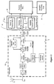
- FIG. 2 is a block diagram representing one example, among others, of a typical operation of a global navigation satellite system receiver (or a spread spectrum receiver) 10 wherein the present invention can be applied.
- the receiver 10 can be a GPS (global positioning system) receiver, a Galileo receiver, or any other compatible receiver presently available or a subject of future technological advances, according to the present invention.
- GPS global positioning system
- Galileo Galileo receiver
- a typical receiver operation includes receiving the radio frequency signal and converting said radio frequency signal containing a multi-path component to a radio frequency electrical signal 11a by an antenna 11 followed by converting said radio frequency electrical signal 11a to a digital intermediate frequency (IF) signal (or a digital signal) 14 by a preprocessor 12 and providing said digital signal 14 to each of N receiving channel blocks 16-1,16-2, ..., 16-N (N is an integer of at least a value of one) of a receiving module 16 which normally exchanges information with the receiver processing block 36 during its operation and the receiver processing block 36 further communicates with a navigation processing block 19.
- IF intermediate frequency
- the key innovation here involves a novel implementation and design of receiving channel blocks 16-1,16-2, ...,16-N using a novel multi-path detection technique and special processing of the correlation information generated by any block of said receiving channel blocks 16-1, 16-2, ...,16-N according to multi-path processing algorithms described below in regard to Figures 3a-3c , 4a, 4b , and 5 , according to the present invention.
- GNSS receivers use three correlators to track the code phase and the carrier phase of the received satellite signal. Usually these correlators are called early, prompt and late correlators. A code phase is tracked by a delay-locked loop, and a carrier phase is tracked by a phase-locked loop in the traditional GNSS receivers.
- Figure 3a is a diagram showing one example among many others of a correlation triangle 15 (a correlation function as a function of a time delay in chips) for a line of sight (LOS) signal (an ideal case, no multi-path component).
- the correlation function can be represented by an amplitude (or an amplitude parameter) and/or a phase (or phase parameter).
- the correlator output generally, is a complex signal, it has real and imaginary part (often referred to as inphase and quadrature components, I and Q).
- the amplitude parameter is the amplitude of this complex value, and the phase parameter is its phase.
- Figures 3a-3c and 4a-4b discussed here present the amplitude of the correlator output.
- Points marked E, P and L correspond to signals generated by the early, prompt and late correlators, respectively. Points E and L are usually symmetrical in the time delay domain relative to the point P.
- the receiver calculates an error signal describing how far away the prompt correlator is from the peak of the correlation triangle, and tries to keep that error signal at zero.
- the receiver is tracking the received code phase accurately.
- a typical error signal (or an early-minus-late error signal) is the correlation function (e.g., its amplitude parameter) at the E (early) point minus the correlation function at the L (late) point.
- the correlation signals at the E and L points are equal (on the same level), as shown in Figure 3a .
- Figures 3b and 3c demonstrate this situation.
- Figure 3b is an example, among others, of a diagram showing correlation triangle 15-1 for the line of sight signal and a correlation triangle 15-2 for a multi-path signal.
- Figure 3c is a diagram showing a correlation triangle 15 for a combined correlation function for the line of sight and for the multi-path signals shown in Figure 3b .
- the tracking point P is shifted from the peak of the LOS signal by a time delay error 17 .
- the present invention it is possible to introduce more than one of additional (further) early-late correlator pairs, also symmetrical in the time delay relative to the point P but with different time spacing (different time delay), and therefore it is possible to calculate an additional early-minus-late error signal for those further early-late correlator pairs, if it is required by an application (e.g., a more accurate determination is required).
- This is consistent with the main goal of the present invention of determining by the spread spectrum receiver 10 whether the distortion of the received radio frequency signal caused by a multi-path component of said received signal meets said predetermined condition using said pre-selected correlation analysis of said received signal for implementing the multi-path detection analysis and selectivity of the code modulated signals.
- the additional early-minus-late error signal should be also close to zero. Otherwise the correlation triangle is not symmetrical (e.g., said predetermined condition is not met), and the presence of a not acceptable multi-path component can be declared.
- the consequence of said "declaration” can be deselecting said code modulated signal (e.g., from a particular satellite) from further consideration and processing or assigning a smaller weight to information contained in said "multi-path" contaminated CDMA signal than to a "clean" multi-path-free signal.
- the magnitude of the additional early-minus-late error signal i.e., how much this additional early-minus-late error signal deviates from zero
- the magnitude of the additional early-minus-late error signal can be used to determine how much the weight of a signal from a particular satellite should be reduced in position calculations.
- the receiver calculates the phase of the prompt correlator, and tries to keep the phase close to zero at the prompt point (P point). If there is data modulation present in the received signal, e.g., a Costas loop can be used, otherwise (no data modulation) a plain phase-locked loop is enough.
- the multi-path signal has a different Doppler frequency than the LOS signal, thus the correlation triangle will be distorted also in a phase domain, and the phase tracking will be also in error. That means, e.g., that the phase (or the phase parameter of the correlation signal) of correlators at E, L, E1 and L1 can be different from zero (for the correlator P) and from each other.
- the phase of the prompt correlator signal and of all other correlator signals are the same, and the phase of the prompt correlator is driven to zero by the receiver.
- the phase of the prompt correlator output and other correlators is no longer the same. If the receiver is phase-locked, the phase of the prompt correlator signal remains zero, but the output signals of other correlators are no longer zeros due to the multi-path effects. Therefore, according to the present invention, the multi-path component can be detected by observing the phase difference between the output signals from different correlators.
- the phases of the output signals from the different correlators will be different disclosing the presence of the multi-path component and the phase method can be applied directly after the radio frequency signal acquisition without the need to wait for tracking to stabilize. It is also noted that for phase comparisons, the correlators do not have to be symmetrical about the prompt point.
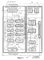
- Figure 5 is a block diagram representing one example, among others, for implementing the receiving channel block 16-1,16-2, ..., or 16-N of a receiving module 16 and the receiving processing block 36, both contained in the spread spectrum receiver 10, according to the present invention.
- Figure 5 shows components of the module 16 and the block 36 relevant to the present invention.
- the receiving channel block 16-1, 16-2, ..., or 16-N comprises a residual carrier removing block 20 used for generating a data intermediate signal 54 by removing a residual carrier frequency from the digital IF signal 14 using a feedback of a phase-loop (or phase-locked loop) 46, i.e., in response to a frequency control signal 50 indicative of said phase-loop feedback from said receiver processing block 36.
- a phase-loop or phase-locked loop
- the receiving channel block 16-1, 16-2, ..., or 16-N also comprises a code generating block 40 used for generating a code signal 58 indicative of a delay-loop (or delay-locked loop) 44 feedback, i.e., in response to a code control signal 38 indicative of said delay-loop feedback from the receiver processing block 36 as a part of a delay-locked loop 44.
- a code generating block 40 used for generating a code signal 58 indicative of a delay-loop (or delay-locked loop) 44 feedback, i.e., in response to a code control signal 38 indicative of said delay-loop feedback from the receiver processing block 36 as a part of a delay-locked loop 44.
- the data intermediate signal 54 is provided to each of five correlators (E1 E, P, L, L1) 24-1, 24-2, ..., 24-5.
- the correlators 24-1 and 24-2 correspond to the early correlators E1 and E, respectively, described above; the correlators 24-4 and 24-5 correspond to late correlators L and L1, respectively, described above; and the correlator 24-3 correspond to the prompt correlator described above.
- the code signal 58 is provided to a first delay module 22-1 and then each of five consecutively delayed code signals 25-1, 25-2, ..., 25-5 generated by a corresponding one of five delay modules 22-1, 22-2,..., 22-5 is provided to one corresponding correlator module of said five correlator modules 24-1, 24-2, ..., 25-4, as shown in Figure 5 , wherein said each of said five delayed code signals 25-1, 25-2, ..., 25-5 is consecutively and individually delayed by pre-selected values relative to a previously delayed code signal of said five consecutively delayed code signals 25-1, 25-2, ..., 25-5 starting with the code signal 58 provided by the code generating block 40 to the delay module 22-1.
- the pre-selected delay values are chosen based on the algorithm shown in Figures 4a and 4b , such that the delay signal 25-1 corresponds to the E1 point, the delay signal 25-2 corresponds to the E point, the delay signal 25-3 corresponds to the P point, the delay signal 25-4 corresponds to the L point, and the delay signal 25-5 corresponds to the L1 point.
- Each of the five correlator modules 24-1, 24-2, ..., 24-5 generates a corresponding one of five correlation signals 26-1, 26-2, ..., 26-5 and these correlation signals 26-1, 26-2, ..., 26-5 are provided to the receiver processing block 36 for determining whether the distortion of the received radio frequency signal caused by said multi-path component meets a predetermined condition.
- Each of the five correlation signals 26-1, 26-2, ..., 26-5 can contain an amplitude parameter or a phase parameter or both said amplitude parameter and said phase parameter, such that the correlation triangle shown in Figures 4a and 4b can be generated for the amplitude parameter and a plot of the phase parameter (or a phase parameter plot) as a function of different correlators (said plot is not a straight horizontal line if the multi-path is present because the phase parameter is different for different correlators) can be generated simultaneously, according to the present invention.
- the correlation signals 26-2 and 26-4 (E and L points in Figures 4 and 4b ), provided to a code loop detector 28 of the receiver processing block 36, corresponds to the traditional way of evaluating multi-path effects (e.g., maintaining the difference in the amplitude parameter of the correlation signals 26-2 and 26-4 close to zero through the delay-locked loop 44 using the code control signal 38 as shown in Figure 5 ).
- the correlation signals 26-2, 26-3 and 26-4 i.e., the phase difference between them
- the correlation signals 26-1 and 26-5 can be optionally used without a further need for the correlation signals 26-1 and 26-5 for the determining whether the distortion of the received radio frequency signal caused by said multi-path component meets a predetermined condition (as described above).
- said determining can be implemented by providing said correlation signals 26-1, 26-2, ..., 26-5 (or just 26-2, 26-3 and 26-4) to a correlation phase detector 31 which generates and provides phase parameters of the corresponding correlation signals 26-1, 26-2, ..., 26-5 (or 26-2, 26-3 and 26-4) to a multi-path processing block 32 of said block 36 for performing said determining.
- the block 32 can use a phase difference of signals 26-1, 26-2, ..., 26-5 (or 26-2, 26-3 and 26-4) but also, optionally, can include the phase of the signals 26-1, 26-3 and 26-5 in said determining.
- the correlation signals 26-1 and 26-5 are provided to an additional early-late detector 30 (in an alternative scenario, the block 30 can be combined with the block 28 and/or with the block 31 ) of the receiver processing block 36, as shown in Figure 5 .
- the additional early-late detector 30 can generate the amplitude parameters of the correlation signals 26-1 and 26-5 or directly the difference (the additional early-minus-late error) signal between the correlation signals 26-1 and 26-5 and provides these amplitude parameters or said difference to the multi-path processing block 32, while maintaining the difference in the amplitude parameter of the correlation signals 26-2 and 26-4 close to zero through the delay-locked loop 44 using the signal 38 as . described above.
- the multi-path processing block 32 determines, based on the inputs from the blocks 28, 31 and /or 30, whether the distortion of the received radio frequency signal caused by said multi-path component meets said predetermined condition. If the predetermined condition is not met, then the presence of the not acceptable multi-path component can be declared, such that, according to the present invention, the received radio code modulated signal (e.g., from a particular satellite) is deselected from further consideration and processing beyond the receiver processing block 36, i.e., no further signal is provided to the navigation processing block 19.
- the received radio code modulated signal e.g., from a particular satellite
- an intermediate measure can be assigning a smaller weight to information contained in said multi-path "contaminated” code modulated signal than to a "clean" multi-path-free signal, but still providing this "contaminated” code modulated signal to the navigation processing block 19 as explained above. If, however, the multi-path processing block 32 determines that the distortion of the received radio frequency signal caused by said multi-path component meets said predetermined condition, it provides said code modulated signal to the navigation processing block 19 for further processing.
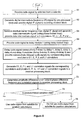
- Figure 6 is a flow chart representing an example of a multi-path selective detection operation of the global navigation satellite system receiver (spread spectrum receiver) 10, according to the present invention.
- a method according to the present invention in a first step 60, the radio frequency signal containing said multi-path component is received and converted to the radio frequency electrical signal 11 a by an antenna 11.
- said radio frequency electrical signal 11a is converted to a digital intermediate frequency (IF) signal (or a digital signal) 14 by a preprocessor 12 and said digital signal 14 is provided to each ofN receiving channel blocks 16-1,16-2, ...,16-N.
- IF digital intermediate frequency
- a next step 64 the residual carrier frequency is removed from the digital IF signal and the data intermediate signal is generated (using the carrier phase-locked loop) and provided to each of five correlators (E1 E, P, L, L1) 24-1, 24-2, ..., 24-5.
- a next step 66 the code signal 58 indicative of a delay-loop (or delay-locked loop) 44 feedback is generated and provided to the delay module 22-1.
- each of five consecutively delayed code signals 25-1, 25-2, ..., 25-5 generated by a corresponding one of five delay modules 22-1, 22-2,..., 22-5 is provided to one corresponding correlator module of said five correlator modules 24-1, 24-2, ..., 25-4, wherein said each of said five delayed code signals 25-1, 25-2, ..., 25-5 is consecutively and individually delayed by pre-selected values relative to a previously delayed code signal of said five consecutively delayed code signals 25-1, 25-2, ..., 25-5 starting with the code signal 58.
- the pre-selected delay values are chosen based on the algorithm shown in Figures 4a and 4b , such that the delay signal 25-1 corresponds to the E1 point, the delay signal 25-2 corresponds to the E point, the delay signal 25-3 corresponds to the P point, the delay signal 25-4 corresponds to the L point, and the delay signal 25-1 corresponds to the L1 point.
- Each of the five correlator modules 24-1, 24-2, ..., 24-5 generates a corresponding one of five correlation signals 26-1, 26-2, ..., 26-5 (E1 E, P, L, L1) and these correlation signals 26-1, 26-2, ..., 26-5 (both amplitude and phase) are provided to the receiver processing block 36 for determining whether the distortion of the received radio frequency signal caused by said multi-path component meets a predetermined condition.
- the receiver processing block 36 generates the difference (the additional early-minus-late error) signal between the correlation signals 26-1 and 26-5 (E1 and L1), and /or the phase difference between any correlation signals.
- a next step 74 it is determined by the receiver processing block 36 whether the predetermined condition is met (for the amplitude or/and for the phase) based on the results of step 72. If that is not the case, the evaluated radio signal from the particular satellite is not used (shown as step 76 ) for position calculations (e.g., the signal is not passed to the navigation processing block 19 ). If, however, it is determined that the predetermined condition is met, in a next step the evaluated radio signal from the particular satellite is used for position calculations (e.g., the signal is passed to the navigation processing block 19 ).
- a terminal (or a user equipment, UE) 84 is a communication device, such as a mobile device or a mobile phone, containing a CDMA receiver 83 according to the present invention.
- the CDMA receiver 83 can be, for instance, the spread spectrum (GNSS) receiver 10 described in the examples of Figures 2 and 5 .
- said CDMA receiver 83 contains a receiving module 16 with the key innovation as described above.
- the block 16 can be built as a removable unit.
- the receiving module 16 can be, for example, a combination of receiving channel blocks 16-1,16-2, ..., and 16-N as presented in Figure 2 .
- Figure 7 shows P satellites 86-1, ..., 86-P sending P satellite signals 80-1, ..., 80-P, to the CDMA spread spectrum receiver 83.
- Figure 7 also shows a base station 85, which communicates with the terminal 84 by sending, e.g., a mobile CDMA communication signal 82a to the CDMA spread spectrum receiver 83 and receiving back the outgoing communication signal 82b from the terminal 84.
- the signals 80-1, ..., 80-P and 82a can contain the multi-path components and are processed by the receiving module 16 as described in the present invention.
Description
- This invention generally relates to spread spectrum receiver, and more specifically to a multi-path detection analysis and selectivity of code modulated signals using spread spectrum receivers.
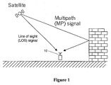
- GNSS (global navigation satellite system) receivers determine their position by making accurate range measurements to transmitting satellites. However, the accuracy may be severely decreased if the signals are distorted by multi-path effects. Typically a multi-path environment is especially bad in urban areas where there are many reflecting surfaces as shown in
Figure 1 . Unfortunately, many mobile phone users live in the urban areas as well. - Traditionally GNSS receivers try to minimize the harmful effect of multi-path by making the range measurements less sensitive to multi-path. Several such methods are known, e.g., a narrow correlator described by A.J. van Dierendonck, P Fenton and T. Ford in "Theory and Performance of Narrow Correlator Spacing in a GPS Receiver", Navigation, Vol. 39, No. 3, Fall 1992, pp. 265-283, a strobe correlator described by L. Garin, F. van Diggelen and J-M. Rousseau, in "Strobe & Edge Correlator Multi-path Mitigation for Code", ION GPS-96, September 17-20,1996, Kansas City, Missouri, pp. 657-664, and a multi-path estimating delay lock loop described by R. D. J. van Nee, in "The Multi-path Estimating Delay Lock Loop", ISSSTA-92, November 29 - December 2, 1992, Yokohama, Japan, pp. 39-42.
- Typically a GPS (global positioning system) receiver sees 8-12 satellites simultaneously. In the future, when a European Galileo system is operational, the number of visible satellites will be doubled to 16-24 for a combined GPS-Galileo receiver. However, only four satellites are needed for a position calculation. Hence it would be advantageous to select for position calculation the signals that are the least corrupted by a multi-path propagation.
-
EP 1 117 187 A2 -
US 6,532,255 B1 describes a method relating to an arrangement for minimizing the autocorrelation error in the demodulation of a spread-spectrum signal subject to multipath propagation. -
WO 2004/036238 A1 describes processing of spread spectrum signals, where a continuous signal of a comparatively high frequency is received. Information obtained from data words is correlated with at least one representation of a signal source specific code sequence, which has been pre-generated in the form of a code vector. -
EP 1 143 652 A2 - According to a first aspect of the present invention, there is provided a method for a multi-path detection analysis of a radio frequency signal by a spread spectrum receiver, comprising: receiving a radio frequency signal containing a multi-path component and converting the radio frequency signal to a digital signal; and detecting the multi-path component and determining using at least two pairs of correlation signals, each pair being symmetrical relative to a prompt signal, whether a distortion of the radio frequency signal caused by the multi-path component meets a predetermined condition using a correlation analysis of the digital signal with the at least two pairs of the correlation signals by maintaining equal the correlation signals of one pair of the two pairs using a delay-locked loop and evaluating a difference between the correlation signals of another pair of the two pairs, wherein each correlation signal is generated by a correlator using a delayed code signal and a data intermediate signal generated from the digital signal, and making a decision whether to further process the received radio frequency signal using results of the multi-path detection analysis.
- The determining may be performed by a processing means. The radio frequency signal may be used for further processing beyond the processing means after making the decision, only if the distortion meets the predetermined condition, for implementing a selective function of the multi-path detection operation.
- The digital signal may be generated by converting the radio frequency signal to a radio frequency electrical signal with subsequent converting the radio frequency electrical signal to a digital signal.
- The radio frequency signal may be a code division multiple access signal.
- Prior to the determining, the correlation analysis of the digital signal may be performed by a receiving channel block of the spread spectrum receiver, and the analysis may comprises: generating a data intermediate signal by removing a residual carrier frequency from the digital signal using a phase-loop feedback and providing the data intermediate signal to each of K correlators of the receiving channel block, wherein K is an odd integer of at least a value of five; providing a code signal indicative of a delay-loop feedback to a first delay module of the receiver processing block; providing each of K consecutively delayed code signals to one corresponding correlator module of K correlator modules, wherein the each of the K delayed code signals is consecutively and individually delayed by pre-selected values relative to a previously delayed code signal of the K consecutively delayed code signals starting with the code signal provided by the receiver processing block; and generating each of K correlation signals by a corresponding one of the K correlator modules using the data intermediate signal and the K delayed code signals and providing the K correlation signals to the receiver processing block for the determining, wherein the each of the K correlation signals contains an amplitude parameter or a phase parameter or both the amplitude parameter and the phase parameter. The distortion of the radio frequency signal caused by the multi-path component may be evaluated in the processing means using the predetermined condition by comparing the amplitude parameter of an Mth correlation signal of the K correlation signals generated using an Mth delayed code signal of the K consecutively delayed code signals, wherein M = 1, or 2 ... or (K-1)/2, and the amplitude parameter of a corresponding Lth correlation signal of the K consecutively delayed code signals generated using a corresponding Lth delayed code signal of the K correlation signals, wherein L = K, or K-1... or (K+3)/2. The amplitude parameter of two correlation signals of the K correlation signals, generated by corresponding correlation modules using corresponding delayed code signals of the K consecutively delayed code signals delayed by (K-1)/2 and (K+3)/2 times respectively, may be maintained equal using a delay-locked loop of the spread spectrum receiver. The distortion of the radio frequency signal caused by the multipath component may be evaluated by the processing means by comparing amplitude parameter of a first of the K correlation signals, generated using a first delayed code signal of the K consecutively delayed code signals and a last of the K correlation signals generated using a last delayed code signal of the K consecutively delayed code signals using the predetermined condition. K may be equal to 5.
- The phase parameter of one correlation signal of the K correlation signals, generated by a corresponding correlation module using a corresponding delayed code signal of the K consecutively delayed code signals delayed by (K+1)/2 times, may be maintained to be zero using a phase-locked loop, and phase parameters of the K correlation signals may be provided to the receiver processing block for the determining. The code signal may be generated by a code generating block of the receiving channel block in response to a code control signal indicative of the delay-loop feedback from the receiver processing block as a part of a delay-locked loop. The data intermediate signal may be generated by a residual carrier removing block of the receiving channel block in response to a frequency control signal indicative of the phase-loop feedback from the receiver processing block.
- The method may comprise: tracking to zero an early-minus-late signal of one of the at least two pairs of the correlation signals; and using a further early-minus-late signal of another of the at least two pairs of the correlation signals for the determining.
- According to a second aspect of the present invention, there is provided a computer program product comprising: a computer readable storage structure embodying computer program code thereon for execution by a computer processor with the computer program code, wherein the computer program code comprises instructions for performing a method according to any preceding claim, indicated as being performed by any component of the spread spectrum receiver, or a terminal containing the spread spectrum receiver.
- According to a third aspect of the present invention, there is provided a spread spectrum receiver comprising: means for performing a correlation analysis of a digital signal generated from a radio frequency signal comprising a multi-path component using at least two pairs of correlation signals, each pair being symmetrical relative to a prompt signal, by maintaining equal the correlation signals of one pair of the two pairs using a delay-locked loop and evaluating a difference between the correlation signals of another pair of the two pairs, wherein each correlation signal is generated by a correlator using a delayed code signal and a data intermediate signal generated from the digital signal; and processing means for detecting the multi-path component and determining whether a distortion of the radio frequency signal caused by the multi-path component meets a predetermined condition using a the correlation analysis of the digital signal, and for making a decision whether to further process the received radio frequency signal using results of the multi-path detection analysis for implementing a multi-path detection analysis of the radio frequency signal by the spread spectrum receiver.
- The radio frequency signal may be used by the spread spectrum receiver for further processing beyond the processing means after making the decision, only if the distortion meets the predetermined condition, for implementing a selective function of the multi-path detection operation of the spread spectrum receiver.
- The radio frequency signal may be a code division multiple access signal.
- The correlation analysis performing means may comprise N receiving channel blocks, N being an integer of at least a value of one, and each of the N receiving channel blocks may comprises: means for generating a data intermediate signal by removing a residual carrier frequency from the digital signal using a phase-loop feedback; means for generating a code signal indicative of a delay-loop feedback; K correlator modules, wherein K is an odd integer of at least a value of three, for generating each of K correlation signals by a corresponding one of the K correlator modules using the data intermediate signal and K delayed code signals and for providing the K correlation signals to the receiver processing block for the determining whether a distortion of the radio frequency signal caused by the multipath component meets a predetermined condition using a correlation analysis of the digital signal, wherein the each of the K correlation signals contains an amplitude parameter or a phase parameter or both the amplitude parameter and the phase parameter; and K delay modules, for providing each of K consecutively delayed code signals to one corresponding correlator module of the K correlator modules, wherein the each of the K delayed code signals is consecutively and individually delayed by pre-selected values relative to a previously delayed code signal of the K consecutively delayed code signals starting with the code signal provided to a first delay module out of the K delay modules by the receiver processing block. The distortion of the radio frequency signal caused by the multi-path component may be evaluated by the processing means using the predetermined condition by comparing the amplitude parameter of an Mth correlation signal of the K correlation signals generated using an Mth delayed code signal of the K consecutively delayed code signals, wherein M = 1,or 2 ... or (K-1)/2, and the amplitude parameter of a corresponding Lth correlation signal of the K consecutively delayed code signals generated using a corresponding Lth delayed code signal of the K correlation signals, wherein L = K, or K-1... or (K+3)/2. The amplitude parameter of two correlation signals of the K correlation signals, generated by corresponding correlation modules using corresponding delayed code signals of the K consecutively delayed code signals delayed by (K-1)/2 and (K+3)/2 times respectively, may be maintained equal using the predetermined condition. The distortion of the radio frequency signal caused by the multi-path component may be evaluated by the processing means by comparing amplitude parameter of a first of the K correlation signals, generated using a first delayed code signal of the K consecutively delayed code signals and a last of the K correlation signals generated using a last delayed code signal of the K consecutively delayed code signals. K may be equal to 5.
- The phase parameter of one correlation signal of the K correlation signals, generated by a corresponding correlator module of the K correlator modules using a corresponding delayed code signal of the K consecutively delayed code signals delayed by (K+1)/2 times, may be maintained to be zero using a phase-locked loop of the spread spectrum receiver, and phase parameters of the K correlation signals may be provided to the receiver processing block for the determining.
- The receiving channel block may comprise a code generating block, for generating the code signal in response to a code control signal indicative of the delay-loop feedback from the processing means as a part of a delay-locked loop.
- The receiving channel block may comprise a residual carrier removing block for generating the data intermediate signal in response to a frequency control signal indicative of the phase-loop feedback from the receiver processing block.
- The spread spectrum receiver may comprise: an antenna, responsive to the radio frequency signal containing a multi-path component, for providing a radio frequency electrical signal; and a preprocessor, responsive to the radio frequency electrical signal, for providing the digital signal.
- The spread spectrum receiver may be configured to track to zero an early-minus-late signal of another of the at least two pairs of the correlation signals for the determining.
- The spread spectrum receiver may be a global navigation satellite system receiver, a global positioning system receiver or a Galileo receiver.
- There may be provided a system comprising: a satellite, for providing a radio frequency signal; a base station, for providing a further radio frequency signal used for mobile communications; and a terminal, responsive to the radio frequency signal or to the further radio frequency signal, both containing a multi-path component, wherein the terminal comprises the spread spectrum receiver.
- For a better understanding of the nature and objects of the present invention, reference is made to the following detailed description taken in conjunction with the following drawings, in which:
-
Figure 1 is a diagram of multi-path scenario; -
Figure 2 is a block diagram representing an example of a global navigation satellite system receiver (spread spectrum receiver); -
Figure 3 a is a diagram showing a correlation triangle for a line of sight signal; -
Figure 3b is a diagram showing correlation triangles for a line of sight signal and for a multi-path signal; -
Figure 3c is a diagram showing a correlation triangle for combined line of sight and multi-path signals; -
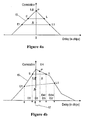
Figure 4a is a diagram showing a correlation triangle for a line of sight signal (multi-path-free case) with additional correlation signals, according to the present invention; -
Figure 4b is a diagram showing a correlation triangle for a multi-path case with additional correlation signals, according to the present invention; -
Figure 5 is a block diagram representing an example of a single receiving channel and a receiving processing block within a global navigation satellite system receiver (spread spectrum receiver), according to the present invention; -
Figure 6 is a flow chart representing an example of a multi-path selective detection operation of a global navigation satellite system receiver (spread spectrum receiver), according to the present invention; and -
Figure 7 is a diagram showing an example of a terminal with a spread spectrum receiver capable of a multi-path selective detection operation for processing radio frequency signals from satellites and/or base stations. - The present invention provides a method for a multi-path detection analysis and selectivity of code modulated signals using spread spectrum receivers using a correlation technique. The invention is based on determining by the spread spectrum receiver whether a distortion of a received radio frequency signal, caused by a multipath component of said received signal, meets a predetermined condition using a pre-selected correlation analysis of said received signal, thus implementing the multi-path detection analysis and selectivity of the code modulated (e.g., CDMA) signals. This invention is generally applicable to spread spectrum receivers and it is particularly useful in the GNSS receivers, such as GPS (global positioning system) and Galileo receivers. Also, the invention can be applied in a broader sense to any communication system utilizing spread spectrum receivers. It can be applied to mobile phones, e.g., utilizing code-division multiple access (CDMA) or wideband CDMA (WCDMA), where it can be used, for example, for network positioning, where the mobile phone measures ranges to base stations.
- The important goal of this invention is to provide a simple method for identifying signals that are corrupted by multi-path effects, and should thus be given a smaller weight or excluded from position calculations in the GNSS receivers.
-
Figure 2 is a block diagram representing one example, among others, of a typical operation of a global navigation satellite system receiver (or a spread spectrum receiver) 10 wherein the present invention can be applied. Thereceiver 10 can be a GPS (global positioning system) receiver, a Galileo receiver, or any other compatible receiver presently available or a subject of future technological advances, according to the present invention. - A typical receiver operation includes receiving the radio frequency signal and converting said radio frequency signal containing a multi-path component to a radio frequency
electrical signal 11a by anantenna 11 followed by converting said radio frequencyelectrical signal 11a to a digital intermediate frequency (IF) signal (or a digital signal) 14 by apreprocessor 12 and providing saiddigital signal 14 to each of N receiving channel blocks 16-1,16-2, ..., 16-N (N is an integer of at least a value of one) of a receivingmodule 16 which normally exchanges information with thereceiver processing block 36 during its operation and thereceiver processing block 36 further communicates with anavigation processing block 19. The key innovation here involves a novel implementation and design of receiving channel blocks 16-1,16-2, ...,16-N using a novel multi-path detection technique and special processing of the correlation information generated by any block of said receiving channel blocks 16-1, 16-2, ...,16-N according to multi-path processing algorithms described below in regard toFigures 3a-3c ,4a, 4b , and5 , according to the present invention. - Traditional GNSS receivers use three correlators to track the code phase and the carrier phase of the received satellite signal. Usually these correlators are called early, prompt and late correlators. A code phase is tracked by a delay-locked loop, and a carrier phase is tracked by a phase-locked loop in the traditional GNSS receivers.
-
Figure 3a is a diagram showing one example among many others of a correlation triangle 15 (a correlation function as a function of a time delay in chips) for a line of sight (LOS) signal (an ideal case, no multi-path component). For the purpose of this invention the correlation function can be represented by an amplitude (or an amplitude parameter) and/or a phase (or phase parameter). The correlator output, generally, is a complex signal, it has real and imaginary part (often referred to as inphase and quadrature components, I and Q). The amplitude parameter is the amplitude of this complex value, and the phase parameter is its phase.Figures 3a-3c and4a-4b discussed here present the amplitude of the correlator output. Points marked E, P and L correspond to signals generated by the early, prompt and late correlators, respectively. Points E and L are usually symmetrical in the time delay domain relative to the point P. - In the delay-locked loop, the receiver calculates an error signal describing how far away the prompt correlator is from the peak of the correlation triangle, and tries to keep that error signal at zero. When the error signal is zero and there is no multi-path signal, the receiver is tracking the received code phase accurately. A typical error signal (or an early-minus-late error signal) is the correlation function (e.g., its amplitude parameter) at the E (early) point minus the correlation function at the L (late) point. When the error signal (early minus late) is zero, the correlation signals at the E and L points are equal (on the same level), as shown in
Figure 3a . However, when the signal is corrupted by the multi-path reflections, the tracking point is shifted from the peak of the LOS signal.Figures 3b and 3c demonstrate this situation. -
Figure 3b is an example, among others, of a diagram showing correlation triangle 15-1 for the line of sight signal and a correlation triangle 15-2 for a multi-path signal.Figure 3c is a diagram showing acorrelation triangle 15 for a combined correlation function for the line of sight and for the multi-path signals shown inFigure 3b . As shown inFigure 3c the tracking point P is shifted from the peak of the LOS signal by atime delay error 17. - By adding another early-late correlator pair (see points E1 and L1 in
Figures 4a and 4b ), also symmetrical in the time delay domain relative to the point P (time intervals D4=D2 as well as D5=D2 as shown inFigure 4b ) but with a different time spacing (a different time delay), it is possible to calculate an additional early-minus-late error signal using this additional early-late correlator pair. If there are no multipath effects (a multi-path-free case), and the receiver is tracking the signal properly, both the original early-minus-late error and the additional early-minus-late error signals are zeros.Figure 4a presents this situation showing the correlation triangle for the line of sight signal (the multi-path-free case) with additional correlation signals (for the additional early-late correlator pair), according to the present invention; - However, when the multi-path signal is present, the original early-minus-late signal starts to track the distorted composite signal. The original early-minus-late error signal is still zero, because the receiver drives it to zero, although it is not the correct tracking point anymore. However, the additional early and late correlator signals are not at the same level, and thus the additional early-minus-late error signal is not zero. This is due to the fact that the distorted correlation triangle is not symmetrical.
Figure 4b depicts this case showing the correlation triangle for a multipath case with the additional correlation signals (at the E1 and L1 points), according to the present invention. - Also according to the present invention, it is possible to introduce more than one of additional (further) early-late correlator pairs, also symmetrical in the time delay relative to the point P but with different time spacing (different time delay), and therefore it is possible to calculate an additional early-minus-late error signal for those further early-late correlator pairs, if it is required by an application (e.g., a more accurate determination is required). This is consistent with the main goal of the present invention of determining by the
spread spectrum receiver 10 whether the distortion of the received radio frequency signal caused by a multi-path component of said received signal meets said predetermined condition using said pre-selected correlation analysis of said received signal for implementing the multi-path detection analysis and selectivity of the code modulated signals. - Hence, it is possible to detect a multi-path situation by observing the output of two early-minus-late signals with different correlator time delay spacings. Once a good enough signal tracking is obtained (the early-minus-late error signal used to track the received signal is close enough to zero), the additional early-minus-late error signal should be also close to zero. Otherwise the correlation triangle is not symmetrical (e.g., said predetermined condition is not met), and the presence of a not acceptable multi-path component can be declared. According to the present invention, the consequence of said "declaration" can be deselecting said code modulated signal (e.g., from a particular satellite) from further consideration and processing or assigning a smaller weight to information contained in said "multi-path" contaminated CDMA signal than to a "clean" multi-path-free signal. The magnitude of the additional early-minus-late error signal (i.e., how much this additional early-minus-late error signal deviates from zero) gives an approximate estimate of the severity of a multi-path problem. Thus, according to the present invention, the magnitude of the additional early-minus-late error signal can be used to determine how much the weight of a signal from a particular satellite should be reduced in position calculations.
- In the phase-locked loop, the receiver calculates the phase of the prompt correlator, and tries to keep the phase close to zero at the prompt point (P point). If there is data modulation present in the received signal, e.g., a Costas loop can be used, otherwise (no data modulation) a plain phase-locked loop is enough. The multi-path signal has a different Doppler frequency than the LOS signal, thus the correlation triangle will be distorted also in a phase domain, and the phase tracking will be also in error. That means, e.g., that the phase (or the phase parameter of the correlation signal) of correlators at E, L, E1 and L1 can be different from zero (for the correlator P) and from each other.
- In the multi-path-free case, the phase of the prompt correlator signal and of all other correlator signals are the same, and the phase of the prompt correlator is driven to zero by the receiver. However, when multi-path distorts the correlation triangle, the phase of the prompt correlator output and other correlators is no longer the same. If the receiver is phase-locked, the phase of the prompt correlator signal remains zero, but the output signals of other correlators are no longer zeros due to the multi-path effects. Therefore, according to the present invention, the multi-path component can be detected by observing the phase difference between the output signals from different correlators. Even if the receiver is not yet fully locked (e.g., code- and/or phase-locked-loop does not need to be tracking perfectly), the phases of the output signals from the different correlators will be different disclosing the presence of the multi-path component and the phase method can be applied directly after the radio frequency signal acquisition without the need to wait for tracking to stabilize. It is also noted that for phase comparisons, the correlators do not have to be symmetrical about the prompt point.
-
Figure 5 is a block diagram representing one example, among others, for implementing the receiving channel block 16-1,16-2, ..., or 16-N of a receivingmodule 16 and the receivingprocessing block 36, both contained in thespread spectrum receiver 10, according to the present invention.Figure 5 shows components of themodule 16 and theblock 36 relevant to the present invention. - The receiving channel block 16-1, 16-2, ..., or 16-N comprises a residual
carrier removing block 20 used for generating a dataintermediate signal 54 by removing a residual carrier frequency from the digital IFsignal 14 using a feedback of a phase-loop (or phase-locked loop) 46, i.e., in response to afrequency control signal 50 indicative of said phase-loop feedback from saidreceiver processing block 36. The receiving channel block 16-1, 16-2, ..., or 16-N also comprises acode generating block 40 used for generating acode signal 58 indicative of a delay-loop (or delay-locked loop) 44 feedback, i.e., in response to acode control signal 38 indicative of said delay-loop feedback from thereceiver processing block 36 as a part of a delay-lockedloop 44. - The data
intermediate signal 54 is provided to each of five correlators (E1 E, P, L, L1) 24-1, 24-2, ..., 24-5. The correlators 24-1 and 24-2 correspond to the early correlators E1 and E, respectively, described above; the correlators 24-4 and 24-5 correspond to late correlators L and L1, respectively, described above; and the correlator 24-3 correspond to the prompt correlator described above. Thecode signal 58 is provided to a first delay module 22-1 and then each of five consecutively delayed code signals 25-1, 25-2, ..., 25-5 generated by a corresponding one of five delay modules 22-1, 22-2,..., 22-5 is provided to one corresponding correlator module of said five correlator modules 24-1, 24-2, ..., 25-4, as shown inFigure 5 , wherein said each of said five delayed code signals 25-1, 25-2, ..., 25-5 is consecutively and individually delayed by pre-selected values relative to a previously delayed code signal of said five consecutively delayed code signals 25-1, 25-2, ..., 25-5 starting with thecode signal 58 provided by thecode generating block 40 to the delay module 22-1. The pre-selected delay values are chosen based on the algorithm shown inFigures 4a and 4b , such that the delay signal 25-1 corresponds to the E1 point, the delay signal 25-2 corresponds to the E point, the delay signal 25-3 corresponds to the P point, the delay signal 25-4 corresponds to the L point, and the delay signal 25-5 corresponds to the L1 point. - Each of the five correlator modules 24-1, 24-2, ..., 24-5 generates a corresponding one of five correlation signals 26-1, 26-2, ..., 26-5 and these correlation signals 26-1, 26-2, ..., 26-5 are provided to the
receiver processing block 36 for determining whether the distortion of the received radio frequency signal caused by said multi-path component meets a predetermined condition. Each of the five correlation signals 26-1, 26-2, ..., 26-5 can contain an amplitude parameter or a phase parameter or both said amplitude parameter and said phase parameter, such that the correlation triangle shown inFigures 4a and 4b can be generated for the amplitude parameter and a plot of the phase parameter (or a phase parameter plot) as a function of different correlators (said plot is not a straight horizontal line if the multi-path is present because the phase parameter is different for different correlators) can be generated simultaneously, according to the present invention. - The correlation signals 26-2 and 26-4 (E and L points in
Figures 4 and 4b ), provided to acode loop detector 28 of thereceiver processing block 36, corresponds to the traditional way of evaluating multi-path effects (e.g., maintaining the difference in the amplitude parameter of the correlation signals 26-2 and 26-4 close to zero through the delay-lockedloop 44 using thecode control signal 38 as shown inFigure 5 ). - However, according to the present invention, if the multi-path detection is based on the phase information only, so that only the phase parameter plot is generated for the phase parameter, the correlation signals 26-2, 26-3 and 26-4 (i.e., the phase difference between them) provided to a
correlation phase detector 31, can be optionally used without a further need for the correlation signals 26-1 and 26-5 for the determining whether the distortion of the received radio frequency signal caused by said multi-path component meets a predetermined condition (as described above). Indeed, even if the phase of the (prompt) correlator signal 26-3 is kept close to zero using saidfeedback signal 50 generated by the phase-lockedloop 46 as shown inFigure 5 , said determining can be implemented by providing said correlation signals 26-1, 26-2, ..., 26-5 (or just 26-2, 26-3 and 26-4) to acorrelation phase detector 31 which generates and provides phase parameters of the corresponding correlation signals 26-1, 26-2, ..., 26-5 (or 26-2, 26-3 and 26-4) to amulti-path processing block 32 of saidblock 36 for performing said determining. Theblock 32 can use a phase difference of signals 26-1, 26-2, ..., 26-5 (or 26-2, 26-3 and 26-4) but also, optionally, can include the phase of the signals 26-1, 26-3 and 26-5 in said determining. On the other hand, if the multi-path detection is based on evaluating the amplitude parameter or for both the amplitude and phase parameters, according to the present invention, the correlation signals 26-1 and 26-5 are provided to an additional early-late detector 30 (in an alternative scenario, theblock 30 can be combined with theblock 28 and/or with the block 31) of thereceiver processing block 36, as shown inFigure 5 . The additional early-late detector 30 can generate the amplitude parameters of the correlation signals 26-1 and 26-5 or directly the difference (the additional early-minus-late error) signal between the correlation signals 26-1 and 26-5 and provides these amplitude parameters or said difference to themulti-path processing block 32, while maintaining the difference in the amplitude parameter of the correlation signals 26-2 and 26-4 close to zero through the delay-lockedloop 44 using thesignal 38 as . described above. - The
multi-path processing block 32 determines, based on the inputs from theblocks receiver processing block 36, i.e., no further signal is provided to thenavigation processing block 19. Alternatively, an intermediate measure can be assigning a smaller weight to information contained in said multi-path "contaminated" code modulated signal than to a "clean" multi-path-free signal, but still providing this "contaminated" code modulated signal to thenavigation processing block 19 as explained above. If, however, themulti-path processing block 32 determines that the distortion of the received radio frequency signal caused by said multi-path component meets said predetermined condition, it provides said code modulated signal to thenavigation processing block 19 for further processing. -
Figure 6 is a flow chart representing an example of a multi-path selective detection operation of the global navigation satellite system receiver (spread spectrum receiver) 10, according to the present invention. - The flow chart of
Figure 6 only represents one possible scenario among others. In a method according to the present invention, in afirst step 60, the radio frequency signal containing said multi-path component is received and converted to the radio frequencyelectrical signal 11 a by anantenna 11. In anext step 62, said radio frequencyelectrical signal 11a is converted to a digital intermediate frequency (IF) signal (or a digital signal) 14 by apreprocessor 12 and saiddigital signal 14 is provided to each ofN receiving channel blocks 16-1,16-2, ...,16-N. - In a
next step 64, the residual carrier frequency is removed from the digital IF signal and the data intermediate signal is generated (using the carrier phase-locked loop) and provided to each of five correlators (E1 E, P, L, L1) 24-1, 24-2, ..., 24-5. - In a
next step 66, thecode signal 58 indicative of a delay-loop (or delay-locked loop) 44 feedback is generated and provided to the delay module 22-1. - In a
next step 68, each of five consecutively delayed code signals 25-1, 25-2, ..., 25-5 generated by a corresponding one of five delay modules 22-1, 22-2,..., 22-5 is provided to one corresponding correlator module of said five correlator modules 24-1, 24-2, ..., 25-4, wherein said each of said five delayed code signals 25-1, 25-2, ..., 25-5 is consecutively and individually delayed by pre-selected values relative to a previously delayed code signal of said five consecutively delayed code signals 25-1, 25-2, ..., 25-5 starting with thecode signal 58. The pre-selected delay values are chosen based on the algorithm shown inFigures 4a and 4b , such that the delay signal 25-1 corresponds to the E1 point, the delay signal 25-2 corresponds to the E point, the delay signal 25-3 corresponds to the P point, the delay signal 25-4 corresponds to the L point, and the delay signal 25-1 corresponds to the L1 point. - In a
next step 70, Each of the five correlator modules 24-1, 24-2, ..., 24-5 generates a corresponding one of five correlation signals 26-1, 26-2, ..., 26-5 (E1 E, P, L, L1) and these correlation signals 26-1, 26-2, ..., 26-5 (both amplitude and phase) are provided to thereceiver processing block 36 for determining whether the distortion of the received radio frequency signal caused by said multi-path component meets a predetermined condition. In anext step 72, thereceiver processing block 36 generates the difference (the additional early-minus-late error) signal between the correlation signals 26-1 and 26-5 (E1 and L1), and /or the phase difference between any correlation signals. - In a
next step 74, it is determined by thereceiver processing block 36 whether the predetermined condition is met (for the amplitude or/and for the phase) based on the results ofstep 72. If that is not the case, the evaluated radio signal from the particular satellite is not used (shown as step 76) for position calculations (e.g., the signal is not passed to the navigation processing block 19). If, however, it is determined that the predetermined condition is met, in a next step the evaluated radio signal from the particular satellite is used for position calculations (e.g., the signal is passed to the navigation processing block 19). - The present invention can be applied to a variety of applications and not only to the GPS and Galileo satellite navigation systems. The invention can be used equally well with other navigation systems or more generally with any communication systems utilizing a spread spectrum receiver. An example of such a system is shown in
Figure 7 . A terminal (or a user equipment, UE) 84 is a communication device, such as a mobile device or a mobile phone, containing aCDMA receiver 83 according to the present invention. TheCDMA receiver 83 can be, for instance, the spread spectrum (GNSS)receiver 10 described in the examples ofFigures 2 and5 . Moreover, saidCDMA receiver 83 contains a receivingmodule 16 with the key innovation as described above. Theblock 16 can be built as a removable unit. The receivingmodule 16 can be, for example, a combination of receiving channel blocks 16-1,16-2, ..., and 16-N as presented inFigure 2 .Figure 7 shows P satellites 86-1, ..., 86-P sending P satellite signals 80-1, ..., 80-P, to the CDMAspread spectrum receiver 83.Figure 7 also shows abase station 85, which communicates with the terminal 84 by sending, e.g., a mobileCDMA communication signal 82a to the CDMAspread spectrum receiver 83 and receiving back theoutgoing communication signal 82b from the terminal 84. The signals 80-1, ..., 80-P and 82a can contain the multi-path components and are processed by the receivingmodule 16 as described in the present invention. - It is to be understood that the above-described arrangements are only illustrative of the application of the principles of the present invention. Numerous modifications and alternative arrangements may be devised by those skilled in the art without departing from the scope of the present invention, and the appended claims are intended to cover such modifications and arrangements.
Claims (30)
- A method for a multi-path detection analysis of a radio frequency signal by a spread spectrum receiver (10), comprising:receiving a radio frequency signal containing a multi-path component and converting said radio frequency signal to a digital signal; anddetecting said multi-path component and determining using at least two pairs of correlation signals, each pair being symmetrical relative to a prompt signal, whether a distortion of said radio frequency signal caused by said multi-path component meets a predetermined condition using a correlation analysis of said digital signal (14) with said at least two pairs of the correlation signals by maintaining equal the correlation signals of one pair of said two pairs using a delay-locked loop (44) and evaluating a difference between the correlation signals of another pair of said two pairs, wherein each correlation signal (26) is generated by a correlator (24) using a delayed code signal (25) and a data intermediate signal (54) generated from the digital signal, and making a decision whether to further process the received radio frequency signal using results of said multi-path detection analysis.
- A method according to claim 1, wherein said determining is performed by a processing means (36).
- A method according to claim 2, wherein said radio frequency signal is used for further processing beyond said processing means (36) after making said decision, only if said distortion meets said predetermined condition, for implementing a selective function of said multi-path detection operation.
- A method according to claim 1, wherein said digital signal (14) is generated by converting said radio frequency signal to a radio frequency electrical signal (11 a) with subsequent converting said radio frequency electrical signal to a digital signal (14).
- A method according to claim 1, wherein said radio frequency signal is a code division multiple access signal.
- A method according to claim 1, wherein prior to said determining, said correlation analysis of said digital signal (14) is performed by a receiving channel block (16-1, 16-2,..., or 16-N) of said spread spectrum receiver (10), and said analysis comprises:generating a data intermediate signal (54) by removing a residual carrier frequency from said digital signal (14) using a phase-loop feedback and providing said data intermediate signal (54) to each of K correlators of said receiving channel block (16-1, 16-2, ..., or 16-N), wherein K is an odd integer of at least a value of five;providing a code signal (58) indicative of a delay-loop feedback to a first delay module (22-1) of said receiver processing block (36);providing each of K consecutively delayed code signals (25-1, 25-2,...25-K) to one corresponding correlator module of K correlator modules (24-1, 24-2,...24-K), wherein said each of said K delayed code signals (25-1, 25-2, ...25-K) is consecutively and individually delayed by pre-selected values relative to a previously delayed code signal of said K consecutively delayed code signals (25-1, 25-2, ... 25-K) starting with said code signal (58) provided by said receiver processing block (36); andgenerating each of K correlation signals (26-1, 26-2, ... 26-K) by a corresponding one of said K correlator modules (24-1, 24-2, ... 24-h) using said data intermediate signal (54) and said K delayed code signals (25-1, 25-2, ... 25-K) and providing said K correlation signals to said receiver processing block (36) for said determining, wherein said each of said K correlation signals (26-1, 26-2, ... 26-K) contains an amplitude parameter or a phase parameter or both said amplitude parameter and said phase parameter.
- A method according to claim 6, wherein said distortion of said radio frequency signal caused by said multi-path component is evaluated in said processing means (36) using said predetermined condition by comparing said amplitude parameter of an Mth correlation signal of said K correlation signals (26-1, 26-2,...26-K) generated using an Mth delayed code signal of said K consecutively delayed code signals (25-1, 25-2, ...25 K), wherein M = 1, or 2 ... or (K-1)/2, and said amplitude parameter of a corresponding Lth correlation signal of said K consecutively delayed code signals (25-1, 25-2, ... 25-K) generated using a corresponding Lth delayed code signal of said K correlation signals (26-1, 26-2, ... 26-K), wherein L = K, or K-1 ... or (K+3)/2.
- A method according to claim 7, wherein said amplitude parameter of two correlation signals of said K correlation signals (26-1, 26-2, ... 26-K), generated by corresponding correlation modules using corresponding delayed code signals of said K consecutively delayed code signals (25-1, 25-2, ... 25-K) delayed by (K-1)/2 and (K+3)/2 times respectively, is maintained equal using a delay-locked loop of said spread spectrum receiver (10).
- A method according to claim 8, wherein said distortion of said radio frequency signal caused by said multi-path component is evaluated by said processing means (36)by comparing amplitude parameter of a first of said K correlation signals (26-1, 26-2, ...26-K), generated using a first delayed code signal of said K consecutively delayed code signals (25-1, 25-2, ... 25-K) and a last of said K correlation signals (26-1, 26-2,...26-K) generated using a last delayed code signal of said K consecutively delayed code signals using said predetermined condition.
- A method according to claim 9, wherein K=5.
- A method according to claim 6, wherein said phase parameter of one correlation signal of said K correlation signals (26-1, 26-2, ... 26-K), generated by a corresponding correlation module using a corresponding delayed code signal of said K consecutively delayed code signals (25-1, 25-2, ... 25-K) delayed by (h+1)/2 times, is maintained to be zero using a phase-locked loop (46), and wherein phase parameters of said K correlation signals (26-1, 26-2, ... 26-K) are provided to said receiver processing block (36) for said determining.
- A method according to claim 6, wherein said code signal (58) is generated by a code generating block (40) of said receiving channel block (16-1, 16-2, ...., or 16-N) in response to a code control signal (38) indicative of said delay-loop feedback from said receiver processing block (36) as a part of a delay-locked loop (44).
- A method according to claim 6, wherein said data intermediate signal (54) is generated by a residual carrier removing block (20) of said receiving channel block (16-1, 16-2, ..., or 16-N) in response to a frequency control signal (50) indicative of said phase-loop feedback from said receiver processing block (36).
- A method according to any preceding claim, comprising:tracking to zero an early-minus-late signal of one of said at least two pairs of the correlation signals;using a further early-minus-late signal of another of said at least two pairs of the correlation signals for said determining.
- A computer program product comprising: a computer readable storage structure embodying computer program code thereon for execution by a computer processor with said computer program code, wherein said computer program code comprises instructions for performing a method according to any preceding claim, indicated as being performed by any component of the spread spectrum receiver, or a terminal containing said spread spectrum receiver.
- A spread spectrum receiver comprising:means (16) for performing a correlation analysis of a digital signal (14) generated from a radio frequency signal comprising a multi-path component using at least two pairs of correlation signals, each pair being symmetrical relative to a prompt signal, by maintaining equal the correlation signals of one pair of said two pairs using a delay-locked loop (44) and evaluating a difference between the correlation signals of another pair of said two pairs, wherein each correlation signal (26) is generated by a correlator (24) using a delayed code signal (25) and a data intermediate signal generated (54) from the digital signal; andprocessing means (36) for detecting said multi-path component and determining whether a distortion of said radio frequency signal caused by said multi-path component meets a predetermined condition using a said correlation analysis of said digital signal (14), and for making a decision whether to further process the received radio frequency signal using results of said multi-path detection analysis for implementing a multi-path detection analysis of said radio frequency signal by said spread spectrum receiver.
- A spread spectrum receiver (10) of according to claim 16, wherein said radio frequency signal is used by said spread spectrum receiver (10) for further processing beyond said processing means (36) after making said decision, only if said distortion meets said predetermined condition, for implementing a selective function of said multi-path detection operation of the spread spectrum receiver (10).
- A spread spectrum receiver according to claim 16, wherein said radio frequency signal is a code division multiple access signal.
- A spread spectrum receiver according to claim 16, wherein said correlation analysis performing means (16) comprises N receiving channel blocks, N being an integer of at least a value of one, and each of said N receiving channel blocks (16-1, 16-2,..., and 16-N), comprises:means (64) for generating a data intermediate signal (54) by removing a residual carrier frequency from said digital signal (14) using a phase-loop feedback;means (66) for generating a code signal (58) indicative of a delay-loop feedback;K correlator modules (24-1, 24-2,...24-K), wherein K is an odd integer of at least a value of three, for generating (70) each of K correlation signals (26-1, 26-2, ... 26-K) by a corresponding one of said K correlator modules (24-1, 24-2, ... 24-K) using said data intermediate signal (54) and K delayed code signals (25-1, 25-2, ... 25-K) and for providing said K correlation signals to said receiver processing block (36) for said determining whether a distortion of said radio frequency signal caused by said multi-path component meets a predetermined condition using a correlation analysis of said digital signal (14), wherein said each of said K correlation signals (26-1, 26-2, ... 26-K) contains an amplitude parameter or a phase parameter or both said amplitude parameter and said phase parameter; andK delay modules (22-1, 22-2, ...22-K), for providing each of K consecutively delayed code signals (25-1, 25-2, ... 25-K) to one corresponding correlator module of said K correlator modules (24-1, 24-2, ... 24-K), wherein said each of said K delayed code signals (25-1, 25-2, ... 25-K) is consecutively and individually delayed by pre-selected values relative to a previously delayed code signal of said K consecutively delayed code signals (25-1, 25-2, ... 25-K) starting with said code signal (58) provided to a first delay module (22-1) out of said K delay modules by said receiver processing block (36).
- A spread spectrum receiver (10) according to claim 19, wherein and said distortion of said radio frequency signal caused by said multi-path component is evaluated by said processing means (36) using said predetermined condition by comparing said amplitude parameter of an Mth correlation signal of said K correlation signals (26-1, 26-2, ... 26-K) generated using an Mth delayed code signal of said K consecutively delayed code signals (25-1, 25-2, ...25-K), wherein M = 1,or 2 ... or (K-1)/2, and said amplitude parameter of a corresponding Lth correlation signal of said K consecutively delayed code signals (25-1, 25-2, ... 25-K) generated using a corresponding Lth delayed code signal of said K correlation signals (26-1, 26-2,... 26-K), wherein L = K, or K-1 ... or (K+3)/2.
- A spread spectrum receiver (10) according to claim 19, wherein said amplitude parameter of two correlation signals of said K correlation signals (26-1, 26-2, ... 26-K), generated by corresponding correlation modules using corresponding delayed code signals (25-1, 25-2, ... 25-K) of said K consecutively delayed code signals delayed by (K-1)/2 and (K+3)/2 times respectively, is maintained equal using said predetermined condition.
- A spread spectrum receiver (10) according to claim 21, wherein said distortion of said radio frequency signal caused by said multi-path component is evaluated by said processing means (36) by comparing amplitude parameter of a first of said K correlation signals (26-1, 26-2, ... 26-K), generated using a first delayed code signal of said K consecutively delayed code signals (25-1, 25-2, ...25-K) and a last of said K correlation signals (26-1, 26-2, ... 26-K) generated using a last delayed code signal of said K consecutively delayed code signals (25-1, 25-2, ...25-K).
- A spread spectrum receiver (10) according to claim 22, wherein K=5.
- A spread spectrum receiver (10) according to claim 19, wherein said phase parameter of one correlation signal of said K correlation signals (26-1, 26-2, ... 26-K), generated by a corresponding correlator module of said K correlator modules using a corresponding delayed code signal of said K consecutively delayed code signals (25-1, 25-2, ... 25-K) delayed by (K+1)/2 times, is maintained to be zero using a phase-locked loop (46) of said spread spectrum receiver (10), and wherein phase parameters of said K correlation signals (26-1, 26-2, ...26-K) are provided to said receiver processing block (36) for said determining.
- A spread spectrum receiver (10) according to claim 19, wherein said receiving channel block comprises a code generating block, for generating said code signal (58) in response to a code control signal (38) indicative of said delay-loop feedback from said processing means (36) as a part of a delay-locked loop (44).
- A spread spectrum receiver (10) according to claim 19, wherein said receiving channel block comprises a residual carrier removing block for generating said data intermediate signal (54) in response to a frequency control signal (50) indicative of said phase-loop feedback from said receiver processing block (36).
- A spread spectrum receiver according to any one of claims 16 to 26, comprising:an antenna (11), responsive to the radio frequency signal containing a multipath component, for providing a radio frequency electrical signal; anda preprocessor (12), responsive to the radio frequency electrical signal, for providing the digital signal.
- A spread spectrum receiver according to any one of claims 16 to 27, wherein said spread spectrum receiver is configured to track to zero an early-minus-late signal of another of said at least two pairs of the correlation signals for said determining.
- A spread spectrum receiver according to any one of claims 15 to 28, wherein said spread spectrum receiver is a global navigation satellite system receiver, a global positioning system receiver or a Galileo receiver.
- A system comprising:a satellite, for providing a radio frequency signal;a base station, for providing a further radio frequency signal used for mobile communications; anda terminal, responsive to said radio frequency signal or to said further radio frequency signal, both containing a multi-path component, wherein said terminal comprises a spread spectrum receiver (10) according to any one of claims 16 to 29.
Priority Applications (1)
| Application Number | Priority Date | Filing Date | Title |
|---|---|---|---|
| PL05810454T PL1832005T3 (en) | 2004-12-29 | 2005-10-27 | Method for multi-path detection in spread spectrum receivers |
Applications Claiming Priority (2)
| Application Number | Priority Date | Filing Date | Title |
|---|---|---|---|
| US11/026,503 US7440493B2 (en) | 2004-12-29 | 2004-12-29 | Multi-path detection method for CDMA receivers |
| PCT/IB2005/003203 WO2006070223A1 (en) | 2004-12-29 | 2005-10-27 | Method for multi-path detection in spread spectrum receivers |
Publications (3)
| Publication Number | Publication Date |
|---|---|
| EP1832005A1 EP1832005A1 (en) | 2007-09-12 |
| EP1832005A4 EP1832005A4 (en) | 2010-08-18 |
| EP1832005B1 true EP1832005B1 (en) | 2012-12-19 |
Family
ID=36611454
Family Applications (1)
| Application Number | Title | Priority Date | Filing Date |
|---|---|---|---|
| EP05810454A Active EP1832005B1 (en) | 2004-12-29 | 2005-10-27 | Method for multi-path detection in spread spectrum receivers |
Country Status (5)
| Country | Link |
|---|---|
| US (2) | US7440493B2 (en) |
| EP (1) | EP1832005B1 (en) |
| ES (1) | ES2408306T3 (en) |
| PL (1) | PL1832005T3 (en) |
| WO (1) | WO2006070223A1 (en) |
Cited By (1)
| Publication number | Priority date | Publication date | Assignee | Title |
|---|---|---|---|---|
| CN106646362A (en) * | 2016-12-14 | 2017-05-10 | 西北大学 | Passive target positioning method based on multipath signal spatial spectrum |
Families Citing this family (26)
| Publication number | Priority date | Publication date | Assignee | Title |
|---|---|---|---|---|
| US7286592B2 (en) * | 2004-02-24 | 2007-10-23 | Nokia Mobile Phones, Ltd. | Method and apparatus for receiving a signal |
| US8170085B2 (en) * | 2006-03-09 | 2012-05-01 | CSR Technology Holdings Inc. | Multipath error estimation in satellite navigation receivers |
| GB0615930D0 (en) * | 2006-08-10 | 2006-09-20 | Univ Surrey | A receiver of binary offset carrier modulated signals |
| US7817084B2 (en) * | 2006-08-23 | 2010-10-19 | Qualcomm Incorporated | System and/or method for reducing ambiguities in received SPS signals |
| GB0701296D0 (en) * | 2007-01-24 | 2007-02-28 | Univ Surrey | A receiver of multiplexed binary offset carrier (MBOC) modulated signals |
| US8284820B2 (en) * | 2007-10-17 | 2012-10-09 | Mediatek Inc. | Shared processor architecture applied to functional stages configured in a receiver system for processing signals from different transmitter systems and method thereof |
| EP2066040A1 (en) * | 2007-11-27 | 2009-06-03 | Nemerix SA | Multipath mitigation GNSS Receiver |
| US8406280B2 (en) | 2008-03-18 | 2013-03-26 | Argon St, Inc. | System and method for mitigating severe multipath interference for geolocation and navigation |
| US8144054B2 (en) * | 2008-05-20 | 2012-03-27 | Raytheon Company | Satellite receiver and method for navigation using merged satellite system signals |
| US8412093B2 (en) * | 2008-10-22 | 2013-04-02 | Mediatek Inc. | Receiver applying channel selection filter for receiving satellite signal and receiving method thereof |
| US9726764B1 (en) | 2009-12-07 | 2017-08-08 | Rockwell Collins, Inc. | System and mehtod for providing space-based precision position correlations for promoting improved availability, accuracy and integrity |
| US8908744B1 (en) * | 2010-02-10 | 2014-12-09 | Marvell International Ltd. | Discriminator system for timing error detection in presence and absence of multipath conditions |
| US8395544B2 (en) * | 2010-07-01 | 2013-03-12 | Broadcom Corporation | Method and system for inter-delay product test for signal degradation detection in a GNSS receiver |
| CN102508272B (en) * | 2011-11-15 | 2013-09-04 | 中国航天科工信息技术研究院 | Galileo satellite E1B pseudo code tracking method and device |
| JP6069840B2 (en) * | 2012-02-06 | 2017-02-01 | セイコーエプソン株式会社 | Moving speed calculation method and moving speed calculation device |
| KR102065666B1 (en) | 2012-12-12 | 2020-02-11 | 삼성전자 주식회사 | Signal tracking method of global navigation satellite system, signal tracking apparatus and satellite signal receiver having the same |
| US9178561B2 (en) | 2013-09-11 | 2015-11-03 | Marvell World Trade Ltd. | Method and apparatus for correlating signals received from a navigation satellite system |
| US10534087B1 (en) * | 2015-05-31 | 2020-01-14 | United States Of America As Represented By The Secretary Of The Air Force | Differential vector phase locked loop GPS reception method |
| US9780829B1 (en) * | 2016-03-24 | 2017-10-03 | Focal Point Positioning Ltd. | Method, apparatus, computer program, chip set, or data structure for correlating a digital signal and a correlation code |
| SI3438700T1 (en) | 2017-08-02 | 2021-07-30 | Thales Management & Services Deutschland Gmbh | Method for operating a gnss receiver, with gnss signal deselection |
| CN108562916B (en) * | 2018-01-26 | 2019-07-09 | 中国科学院上海天文台 | The method for building up of forward direction GPS multiple path routing model suitable for complicated cold area's freeze thawing earth's surface |
| WO2019219218A1 (en) * | 2018-05-18 | 2019-11-21 | U-Blox Ag | Global navigation satellite system (gnss) multipath mitigation |
| LT3608691T (en) * | 2018-08-08 | 2021-01-25 | Thales Management & Services Deutschland Gmbh | A method for operating a plurality of gnss receivers for detecting satellite signal deformation |
| CN109541647B (en) * | 2018-12-13 | 2019-12-10 | 武汉大学 | GNSS multi-path effect correction method based on semi-celestial sphere grid point model |
| CN110830297B (en) * | 2019-11-07 | 2020-07-03 | 中国人民解放军火箭军工程大学 | Analytic hierarchy process based satellite communication-in-motion communication scheme selection method and system |
| US11681009B1 (en) * | 2021-03-29 | 2023-06-20 | Topcon Positioning Systems, Inc. | Method and device for reducing multipath channel effects on phase measurements in navigation radio systems |
Family Cites Families (12)
| Publication number | Priority date | Publication date | Assignee | Title |
|---|---|---|---|---|
| US5414729A (en) * | 1992-01-24 | 1995-05-09 | Novatel Communications Ltd. | Pseudorandom noise ranging receiver which compensates for multipath distortion by making use of multiple correlator time delay spacing |
| US5347536A (en) * | 1993-03-17 | 1994-09-13 | The United States Of America As Represented By The Administrator Of The National Aeronautics And Space Administration | Multipath noise reduction for spread spectrum signals |
| US5600670A (en) * | 1994-12-21 | 1997-02-04 | Trimble Navigation, Ltd. | Dynamic channel allocation for GPS receivers |
| KR100220140B1 (en) * | 1994-12-28 | 1999-09-01 | 다치카와 게이지 | Device and method for initially synchronizing spread-spectrum code of cdma transmission system |
| US5953367A (en) * | 1995-08-09 | 1999-09-14 | Magellan Corporation | Spread spectrum receiver using a pseudo-random noise code for ranging applications in a way that reduces errors when a multipath signal is present |
| US6917644B2 (en) | 1996-04-25 | 2005-07-12 | Sirf Technology, Inc. | Spread spectrum receiver with multi-path correction |
| DE19842712C1 (en) * | 1998-09-17 | 2000-05-04 | Siemens Ag | Correlation error correction procedure for signal demodulator, involves computing difference between primary and secondary phase values of spreading signals, to compute phase value of local signal |
| GB2351864B (en) * | 1999-07-05 | 2004-05-26 | Symmetricom Inc | A receiver for receiving rf pseudo-random encoded signals |
| US6868110B2 (en) * | 1999-12-01 | 2005-03-15 | The Board Of Trustees Of The Leland Stanford Junior University | Multipath and tracking error reduction method for spread-spectrum receivers |
| JP4316759B2 (en) | 2000-01-13 | 2009-08-19 | 株式会社日立国際電気 | Path recognition method, CDMA wireless communication terminal, and CDMA wireless communication system |
| US6658048B1 (en) | 2000-04-07 | 2003-12-02 | Nokia Mobile Phones, Ltd. | Global positioning system code phase detector with multipath compensation and method for reducing multipath components associated with a received signal |
| SE0203047D0 (en) | 2002-10-15 | 2002-10-15 | Nordnav Technologies Ab | Spread spectrum signal processing |
-
2004
- 2004-12-29 US US11/026,503 patent/US7440493B2/en active Active
-
2005
- 2005-10-27 ES ES05810454T patent/ES2408306T3/en active Active
- 2005-10-27 WO PCT/IB2005/003203 patent/WO2006070223A1/en active Application Filing
- 2005-10-27 EP EP05810454A patent/EP1832005B1/en active Active
- 2005-10-27 PL PL05810454T patent/PL1832005T3/en unknown
-
2008
- 2008-10-21 US US12/288,645 patent/US7702003B2/en active Active
Cited By (2)
| Publication number | Priority date | Publication date | Assignee | Title |
|---|---|---|---|---|
| CN106646362A (en) * | 2016-12-14 | 2017-05-10 | 西北大学 | Passive target positioning method based on multipath signal spatial spectrum |
| CN106646362B (en) * | 2016-12-14 | 2019-11-15 | 西北大学 | A kind of passive type object localization method based on multipath signal spatial spectrum |
Also Published As
| Publication number | Publication date |
|---|---|
| EP1832005A1 (en) | 2007-09-12 |
| EP1832005A4 (en) | 2010-08-18 |
| US20060140254A1 (en) | 2006-06-29 |
| ES2408306T3 (en) | 2013-06-20 |
| PL1832005T3 (en) | 2013-05-31 |
| US7702003B2 (en) | 2010-04-20 |
| WO2006070223A1 (en) | 2006-07-06 |
| US20090147833A1 (en) | 2009-06-11 |
| US7440493B2 (en) | 2008-10-21 |
Similar Documents
| Publication | Publication Date | Title |
|---|---|---|
| EP1832005B1 (en) | Method for multi-path detection in spread spectrum receivers | |
| CA2622484C (en) | Apparatus for and method of correlating to rising chip edges | |
| US6282231B1 (en) | Strong signal cancellation to enhance processing of weak spread spectrum signal | |
| CA2522463C (en) | Apparatus for and method of making pulse-shape measurements | |
| US6725157B1 (en) | Indoor GPS clock | |
| CN107817506B (en) | Cepstral-based multipath mitigation for spread spectrum radio communication signals | |
| US7693211B2 (en) | Fast fourier transform based phase locked loop for navigational receivers | |
| US20090110134A1 (en) | Noise Floor Independent Delay-Locked Loop Discriminator | |
| CA3110047C (en) | Gnss correlation distortion detection and mitigation | |
| US7421011B2 (en) | Performing an acquisition in a receiver | |
| EP3362818B1 (en) | Satellite navigation receiver with fixed point sigma rho filter | |
| US20010004380A1 (en) | Method for synchronizing a receiver, a positioning system, a receiver and an electronic device | |
| EP1734377A1 (en) | Method for designing a receiver for ranging applications | |
| KR20200099958A (en) | System and method for providing multipath mitigation in global navigation satellite system receiver | |
| EP2243035A1 (en) | Measurement of energy potential (signal-to-noise ratio) in digital global navigation satellite systems receivers | |
| Dovis et al. | Turbo dll: An innovative architecture for multipath mitigation in gnss receivers | |
| Khan et al. | Analysis of the satellite navigational data in the Baseband signal processing of Galileo E5 AltBOC signal |
Legal Events
| Date | Code | Title | Description |
|---|---|---|---|
| PUAI | Public reference made under article 153(3) epc to a published international application that has entered the european phase |
Free format text: ORIGINAL CODE: 0009012 |
|
| 17P | Request for examination filed |
Effective date: 20070628 |
|
| AK | Designated contracting states |
Kind code of ref document: A1 Designated state(s): AT BE BG CH CY CZ DE DK EE ES FI FR GB GR HU IE IS IT LI LT LU LV MC NL PL PT RO SE SI SK TR |
|
| DAX | Request for extension of the european patent (deleted) | ||
| A4 | Supplementary search report drawn up and despatched |
Effective date: 20100721 |
|
| REG | Reference to a national code |
Ref country code: DE Ref legal event code: R079 Ref document number: 602005037528 Country of ref document: DE Free format text: PREVIOUS MAIN CLASS: H04B0001707000 Ipc: G01S0019220000 |
|
| RIC1 | Information provided on ipc code assigned before grant |
Ipc: H04B 1/7075 20110101ALI20120620BHEP Ipc: G01S 19/22 20100101AFI20120620BHEP |
|
| GRAP | Despatch of communication of intention to grant a patent |
Free format text: ORIGINAL CODE: EPIDOSNIGR1 |
|
| GRAS | Grant fee paid |
Free format text: ORIGINAL CODE: EPIDOSNIGR3 |
|
| GRAA | (expected) grant |
Free format text: ORIGINAL CODE: 0009210 |
|
| AK | Designated contracting states |
Kind code of ref document: B1 Designated state(s): AT BE BG CH CY CZ DE DK EE ES FI FR GB GR HU IE IS IT LI LT LU LV MC NL PL PT RO SE SI SK TR |
|
| REG | Reference to a national code |
Ref country code: GB Ref legal event code: FG4D |
|
| REG | Reference to a national code |
Ref country code: CH Ref legal event code: EP |
|
| REG | Reference to a national code |
Ref country code: AT Ref legal event code: REF Ref document number: 589662 Country of ref document: AT Kind code of ref document: T Effective date: 20130115 |
|
| REG | Reference to a national code |
Ref country code: DE Ref legal event code: R096 Ref document number: 602005037528 Country of ref document: DE Effective date: 20130214 |
|
| RAP2 | Party data changed (patent owner data changed or rights of a patent transferred) |
Owner name: FRANCE BREVETS |
|
| PG25 | Lapsed in a contracting state [announced via postgrant information from national office to epo] |
Ref country code: LT Free format text: LAPSE BECAUSE OF FAILURE TO SUBMIT A TRANSLATION OF THE DESCRIPTION OR TO PAY THE FEE WITHIN THE PRESCRIBED TIME-LIMIT Effective date: 20121219 Ref country code: SE Free format text: LAPSE BECAUSE OF FAILURE TO SUBMIT A TRANSLATION OF THE DESCRIPTION OR TO PAY THE FEE WITHIN THE PRESCRIBED TIME-LIMIT Effective date: 20121219 Ref country code: FI Free format text: LAPSE BECAUSE OF FAILURE TO SUBMIT A TRANSLATION OF THE DESCRIPTION OR TO PAY THE FEE WITHIN THE PRESCRIBED TIME-LIMIT Effective date: 20121219 |
|
| REG | Reference to a national code |
Ref country code: NL Ref legal event code: T3 |
|
| REG | Reference to a national code |
Ref country code: AT Ref legal event code: MK05 Ref document number: 589662 Country of ref document: AT Kind code of ref document: T Effective date: 20121219 |
|
| REG | Reference to a national code |
Ref country code: LT Ref legal event code: MG4D |
|
| PG25 | Lapsed in a contracting state [announced via postgrant information from national office to epo] |
Ref country code: LV Free format text: LAPSE BECAUSE OF FAILURE TO SUBMIT A TRANSLATION OF THE DESCRIPTION OR TO PAY THE FEE WITHIN THE PRESCRIBED TIME-LIMIT Effective date: 20121219 Ref country code: GR Free format text: LAPSE BECAUSE OF FAILURE TO SUBMIT A TRANSLATION OF THE DESCRIPTION OR TO PAY THE FEE WITHIN THE PRESCRIBED TIME-LIMIT Effective date: 20130320 Ref country code: SI Free format text: LAPSE BECAUSE OF FAILURE TO SUBMIT A TRANSLATION OF THE DESCRIPTION OR TO PAY THE FEE WITHIN THE PRESCRIBED TIME-LIMIT Effective date: 20121219 |
|
| REG | Reference to a national code |
Ref country code: PL Ref legal event code: T3 |
|
| REG | Reference to a national code |
Ref country code: ES Ref legal event code: FG2A Ref document number: 2408306 Country of ref document: ES Kind code of ref document: T3 Effective date: 20130620 |
|
| REG | Reference to a national code |
Ref country code: NL Ref legal event code: SD Effective date: 20130620 |
|
| PG25 | Lapsed in a contracting state [announced via postgrant information from national office to epo] |
Ref country code: IS Free format text: LAPSE BECAUSE OF FAILURE TO SUBMIT A TRANSLATION OF THE DESCRIPTION OR TO PAY THE FEE WITHIN THE PRESCRIBED TIME-LIMIT Effective date: 20130419 Ref country code: BE Free format text: LAPSE BECAUSE OF FAILURE TO SUBMIT A TRANSLATION OF THE DESCRIPTION OR TO PAY THE FEE WITHIN THE PRESCRIBED TIME-LIMIT Effective date: 20121219 Ref country code: SK Free format text: LAPSE BECAUSE OF FAILURE TO SUBMIT A TRANSLATION OF THE DESCRIPTION OR TO PAY THE FEE WITHIN THE PRESCRIBED TIME-LIMIT Effective date: 20121219 Ref country code: CY Free format text: LAPSE BECAUSE OF FAILURE TO SUBMIT A TRANSLATION OF THE DESCRIPTION OR TO PAY THE FEE WITHIN THE PRESCRIBED TIME-LIMIT Effective date: 20121219 Ref country code: AT Free format text: LAPSE BECAUSE OF FAILURE TO SUBMIT A TRANSLATION OF THE DESCRIPTION OR TO PAY THE FEE WITHIN THE PRESCRIBED TIME-LIMIT Effective date: 20121219 Ref country code: BG Free format text: LAPSE BECAUSE OF FAILURE TO SUBMIT A TRANSLATION OF THE DESCRIPTION OR TO PAY THE FEE WITHIN THE PRESCRIBED TIME-LIMIT Effective date: 20130319 Ref country code: CZ Free format text: LAPSE BECAUSE OF FAILURE TO SUBMIT A TRANSLATION OF THE DESCRIPTION OR TO PAY THE FEE WITHIN THE PRESCRIBED TIME-LIMIT Effective date: 20121219 Ref country code: EE Free format text: LAPSE BECAUSE OF FAILURE TO SUBMIT A TRANSLATION OF THE DESCRIPTION OR TO PAY THE FEE WITHIN THE PRESCRIBED TIME-LIMIT Effective date: 20121219 |
|
| PG25 | Lapsed in a contracting state [announced via postgrant information from national office to epo] |
Ref country code: PT Free format text: LAPSE BECAUSE OF FAILURE TO SUBMIT A TRANSLATION OF THE DESCRIPTION OR TO PAY THE FEE WITHIN THE PRESCRIBED TIME-LIMIT Effective date: 20130419 Ref country code: RO Free format text: LAPSE BECAUSE OF FAILURE TO SUBMIT A TRANSLATION OF THE DESCRIPTION OR TO PAY THE FEE WITHIN THE PRESCRIBED TIME-LIMIT Effective date: 20121219 |
|
| PLBE | No opposition filed within time limit |
Free format text: ORIGINAL CODE: 0009261 |
|
| STAA | Information on the status of an ep patent application or granted ep patent |
Free format text: STATUS: NO OPPOSITION FILED WITHIN TIME LIMIT |
|
| PG25 | Lapsed in a contracting state [announced via postgrant information from national office to epo] |
Ref country code: DK Free format text: LAPSE BECAUSE OF FAILURE TO SUBMIT A TRANSLATION OF THE DESCRIPTION OR TO PAY THE FEE WITHIN THE PRESCRIBED TIME-LIMIT Effective date: 20121219 |
|
| 26N | No opposition filed |
Effective date: 20130920 |
|
| PG25 | Lapsed in a contracting state [announced via postgrant information from national office to epo] |
Ref country code: IT Free format text: LAPSE BECAUSE OF FAILURE TO SUBMIT A TRANSLATION OF THE DESCRIPTION OR TO PAY THE FEE WITHIN THE PRESCRIBED TIME-LIMIT Effective date: 20121219 |
|
| REG | Reference to a national code |
Ref country code: DE Ref legal event code: R097 Ref document number: 602005037528 Country of ref document: DE Effective date: 20130920 |
|
| REG | Reference to a national code |
Ref country code: HU Ref legal event code: AG4A Ref document number: E017858 Country of ref document: HU |
|
| PG25 | Lapsed in a contracting state [announced via postgrant information from national office to epo] |
Ref country code: MC Free format text: LAPSE BECAUSE OF FAILURE TO SUBMIT A TRANSLATION OF THE DESCRIPTION OR TO PAY THE FEE WITHIN THE PRESCRIBED TIME-LIMIT Effective date: 20121219 |
|
| REG | Reference to a national code |
Ref country code: CH Ref legal event code: PL |
|
| REG | Reference to a national code |
Ref country code: IE Ref legal event code: MM4A |
|
| PG25 | Lapsed in a contracting state [announced via postgrant information from national office to epo] |
Ref country code: CH Free format text: LAPSE BECAUSE OF NON-PAYMENT OF DUE FEES Effective date: 20131031 Ref country code: LI Free format text: LAPSE BECAUSE OF NON-PAYMENT OF DUE FEES Effective date: 20131031 |
|
| REG | Reference to a national code |
Ref country code: DE Ref legal event code: R081 Ref document number: 602005037528 Country of ref document: DE Owner name: FRANCE BREVETS, FR Free format text: FORMER OWNER: NOKIA CORPORATION, ESPOO, FI Effective date: 20140624 Ref country code: DE Ref legal event code: R081 Ref document number: 602005037528 Country of ref document: DE Owner name: FRANCE BREVETS, FR Free format text: FORMER OWNER: NOKIA CORP., ESPOO, FI Effective date: 20121219 Ref country code: DE Ref legal event code: R081 Ref document number: 602005037528 Country of ref document: DE Owner name: FRANCE BREVETS, FR Free format text: FORMER OWNER: NOKIA CORP., 02610 ESPOO, FI Effective date: 20121219 Ref country code: DE Ref legal event code: R081 Ref document number: 602005037528 Country of ref document: DE Owner name: FRANCE BREVETS, FR Free format text: FORMER OWNER: NOKIA CORPORATION, 02610 ESPOO, FI Effective date: 20140624 |
|
| PG25 | Lapsed in a contracting state [announced via postgrant information from national office to epo] |
Ref country code: IE Free format text: LAPSE BECAUSE OF NON-PAYMENT OF DUE FEES Effective date: 20131027 |
|
| PG25 | Lapsed in a contracting state [announced via postgrant information from national office to epo] |
Ref country code: LU Free format text: LAPSE BECAUSE OF NON-PAYMENT OF DUE FEES Effective date: 20131027 |
|
| REG | Reference to a national code |
Ref country code: FR Ref legal event code: PLFP Year of fee payment: 12 |
|
| REG | Reference to a national code |
Ref country code: FR Ref legal event code: PLFP Year of fee payment: 13 |
|
| REG | Reference to a national code |
Ref country code: FR Ref legal event code: PLFP Year of fee payment: 14 |
|
| PGFP | Annual fee paid to national office [announced via postgrant information from national office to epo] |
Ref country code: NL Payment date: 20210928 Year of fee payment: 17 Ref country code: FR Payment date: 20210930 Year of fee payment: 17 |
|
| PGFP | Annual fee paid to national office [announced via postgrant information from national office to epo] |
Ref country code: GB Payment date: 20210922 Year of fee payment: 17 Ref country code: PL Payment date: 20210930 Year of fee payment: 17 |
|
| PGFP | Annual fee paid to national office [announced via postgrant information from national office to epo] |
Ref country code: ES Payment date: 20211109 Year of fee payment: 17 Ref country code: TR Payment date: 20211026 Year of fee payment: 17 Ref country code: DE Payment date: 20210923 Year of fee payment: 17 |
|
| PGFP | Annual fee paid to national office [announced via postgrant information from national office to epo] |
Ref country code: HU Payment date: 20211004 Year of fee payment: 17 |
|
| REG | Reference to a national code |
Ref country code: DE Ref legal event code: R119 Ref document number: 602005037528 Country of ref document: DE |
|
| REG | Reference to a national code |
Ref country code: NL Ref legal event code: MM Effective date: 20221101 |
|
| GBPC | Gb: european patent ceased through non-payment of renewal fee |
Effective date: 20221027 |
|
| PG25 | Lapsed in a contracting state [announced via postgrant information from national office to epo] |
Ref country code: NL Free format text: LAPSE BECAUSE OF NON-PAYMENT OF DUE FEES Effective date: 20221101 Ref country code: HU Free format text: LAPSE BECAUSE OF NON-PAYMENT OF DUE FEES Effective date: 20221028 Ref country code: FR Free format text: LAPSE BECAUSE OF NON-PAYMENT OF DUE FEES Effective date: 20221031 Ref country code: DE Free format text: LAPSE BECAUSE OF NON-PAYMENT OF DUE FEES Effective date: 20230503 |
|
| PG25 | Lapsed in a contracting state [announced via postgrant information from national office to epo] |
Ref country code: GB Free format text: LAPSE BECAUSE OF NON-PAYMENT OF DUE FEES Effective date: 20221027 |
|
| REG | Reference to a national code |
Ref country code: ES Ref legal event code: FD2A Effective date: 20231204 |
|
| PG25 | Lapsed in a contracting state [announced via postgrant information from national office to epo] |
Ref country code: ES Free format text: LAPSE BECAUSE OF NON-PAYMENT OF DUE FEES Effective date: 20221028 |
|
| PG25 | Lapsed in a contracting state [announced via postgrant information from national office to epo] |
Ref country code: ES Free format text: LAPSE BECAUSE OF NON-PAYMENT OF DUE FEES Effective date: 20221028 |