EP1833231A2 - Telescopic telephone - Google Patents
Telescopic telephone Download PDFInfo
- Publication number
- EP1833231A2 EP1833231A2 EP07111051A EP07111051A EP1833231A2 EP 1833231 A2 EP1833231 A2 EP 1833231A2 EP 07111051 A EP07111051 A EP 07111051A EP 07111051 A EP07111051 A EP 07111051A EP 1833231 A2 EP1833231 A2 EP 1833231A2
- Authority
- EP
- European Patent Office
- Prior art keywords
- telephone
- spring
- telephone according
- keyboard
- relation
- Prior art date
- Legal status (The legal status is an assumption and is not a legal conclusion. Google has not performed a legal analysis and makes no representation as to the accuracy of the status listed.)
- Granted
Links
Images


Classifications
-
- H—ELECTRICITY
- H04—ELECTRIC COMMUNICATION TECHNIQUE
- H04M—TELEPHONIC COMMUNICATION
- H04M1/00—Substation equipment, e.g. for use by subscribers
- H04M1/02—Constructional features of telephone sets
- H04M1/0202—Portable telephone sets, e.g. cordless phones, mobile phones or bar type handsets
- H04M1/0206—Portable telephones comprising a plurality of mechanically joined movable body parts, e.g. hinged housings
- H04M1/0208—Portable telephones comprising a plurality of mechanically joined movable body parts, e.g. hinged housings characterized by the relative motions of the body parts
- H04M1/0214—Foldable telephones, i.e. with body parts pivoting to an open position around an axis parallel to the plane they define in closed position
-
- H—ELECTRICITY
- H01—ELECTRIC ELEMENTS
- H01Q—ANTENNAS, i.e. RADIO AERIALS
- H01Q1/00—Details of, or arrangements associated with, antennas
- H01Q1/12—Supports; Mounting means
- H01Q1/22—Supports; Mounting means by structural association with other equipment or articles
- H01Q1/24—Supports; Mounting means by structural association with other equipment or articles with receiving set
- H01Q1/241—Supports; Mounting means by structural association with other equipment or articles with receiving set used in mobile communications, e.g. GSM
- H01Q1/242—Supports; Mounting means by structural association with other equipment or articles with receiving set used in mobile communications, e.g. GSM specially adapted for hand-held use
- H01Q1/243—Supports; Mounting means by structural association with other equipment or articles with receiving set used in mobile communications, e.g. GSM specially adapted for hand-held use with built-in antennas
-
- H—ELECTRICITY
- H04—ELECTRIC COMMUNICATION TECHNIQUE
- H04M—TELEPHONIC COMMUNICATION
- H04M1/00—Substation equipment, e.g. for use by subscribers
- H04M1/02—Constructional features of telephone sets
- H04M1/0202—Portable telephone sets, e.g. cordless phones, mobile phones or bar type handsets
- H04M1/0206—Portable telephones comprising a plurality of mechanically joined movable body parts, e.g. hinged housings
- H04M1/0208—Portable telephones comprising a plurality of mechanically joined movable body parts, e.g. hinged housings characterized by the relative motions of the body parts
- H04M1/0235—Slidable or telescopic telephones, i.e. with a relative translation movement of the body parts; Telephones using a combination of translation and other relative motions of the body parts
- H04M1/0237—Sliding mechanism with one degree of freedom
-
- H—ELECTRICITY
- H04—ELECTRIC COMMUNICATION TECHNIQUE
- H04M—TELEPHONIC COMMUNICATION
- H04M1/00—Substation equipment, e.g. for use by subscribers
- H04M1/02—Constructional features of telephone sets
- H04M1/0202—Portable telephone sets, e.g. cordless phones, mobile phones or bar type handsets
- H04M1/0206—Portable telephones comprising a plurality of mechanically joined movable body parts, e.g. hinged housings
- H04M1/0208—Portable telephones comprising a plurality of mechanically joined movable body parts, e.g. hinged housings characterized by the relative motions of the body parts
- H04M1/0214—Foldable telephones, i.e. with body parts pivoting to an open position around an axis parallel to the plane they define in closed position
- H04M1/0216—Foldable in one direction, i.e. using a one degree of freedom hinge
-
- H—ELECTRICITY
- H04—ELECTRIC COMMUNICATION TECHNIQUE
- H04M—TELEPHONIC COMMUNICATION
- H04M1/00—Substation equipment, e.g. for use by subscribers
- H04M1/02—Constructional features of telephone sets
- H04M1/03—Constructional features of telephone transmitters or receivers, e.g. telephone hand-sets
-
- H—ELECTRICITY
- H04—ELECTRIC COMMUNICATION TECHNIQUE
- H04M—TELEPHONIC COMMUNICATION
- H04M1/00—Substation equipment, e.g. for use by subscribers
- H04M1/02—Constructional features of telephone sets
- H04M1/23—Construction or mounting of dials or of equivalent devices; Means for facilitating the use thereof
-
- H—ELECTRICITY
- H04—ELECTRIC COMMUNICATION TECHNIQUE
- H04M—TELEPHONIC COMMUNICATION
- H04M1/00—Substation equipment, e.g. for use by subscribers
- H04M1/72—Mobile telephones; Cordless telephones, i.e. devices for establishing wireless links to base stations without route selection
- H04M1/724—User interfaces specially adapted for cordless or mobile telephones
-
- H—ELECTRICITY
- H04—ELECTRIC COMMUNICATION TECHNIQUE
- H04M—TELEPHONIC COMMUNICATION
- H04M2250/00—Details of telephonic subscriber devices
- H04M2250/18—Details of telephonic subscriber devices including more than one keyboard unit
Definitions
- the invention relates to the electric and mechanical structure of telephones.
- the invention relates to the structure of a telescopically expanding telephone and to the location of its elements.
- the term telephone here means any hand-held apparatus designed for radio communications and provided with a microphone and a loudspeaker.
- a mobile phone By way of example, we shall here discuss a mobile phone.
- FIGs 1-4 illustrate various prior art solutions designed mainly in order to enlarge the user interface of a small-size telephone.
- the mobile phone 100 illustrated in figure 1 comprises a housing 101 and a turning arm 102 attached to the side of the housing by means of a rotating joint.
- the loudspeaker 103 is provided in the housing 101, and the microphone 104 is located at the end of the turning arm 102.
- the turning arm 102 is turned to a position illustrated by a uniform line in the drawing, and during transport it is turned to a position at the side of the housing 101, illustrated by a dotted line.
- the mobile phone 200 illustrated in figure 2 comprises a housing 201 and a flap 202 attached by a hinge at the bottom edge of the housing.
- the flap 202 In the transport position, the flap 202 covers the keyboard 203, and in preparation for use, the flap 202 is turned to the position illustrated in figure 2, so that the microphone 204 provided at the outer end of said flap 202 comes near to the user's mouth in the regular usage position.
- the regular usage position means that the user holds the telephone in his hand, so that the loudspeaker 205 is pressed against his ear and the flap 202 points more or less towards his chin.
- Figure 3 illustrates a mobile phone 300 provided with a sliding lid, said mobile phone 300 comprising a housing 301 and a lid 302 attached thereto by means of slide rails.
- the lid 302 In the transport position, the lid 302 completely covers the keyboard 303.
- the usage position can be chosen according to how large a part of the keys 303 the user needs.
- Figure 3 illustrates a usage position where the lid 302 is completely open.
- the microphone 304 is located in the bottom part of the lid 302, and the loudspeaker 305 is located in the top part of the housing 301.
- the curved shape of the telephone 300 helps to find a comfortable usage position where the microphone 304 and the loudspeaker 305 are placed in a desired position with respect to the user's mouth and ear.
- the mobile phone illustrated in figure 3 can be called a telescopic telephone, because its length in the direction of a given (curved) dimension can be adjusted by sliding two mutually attached elements in relation to each other in the direction of said dimension.
- FIG. 4 illustrates another known telescopic telephone 400, which is introduced in the Finnish registered design application No. 285/97 .
- the telephone comprises a housing 401 and an upper sliding part 402 including a loudspeaker 403, a display 404 and a small part of the keys 405.
- the housing 401 includes the rest of the keys 406, a microphone 407 and an antenna 408.
- the upper sliding part 402 can be sled on top of the housing 401, so that the keyboard 406 is covered.
- the functional practicality of this embodiment is dubious, because the antenna is easily left inside the user's hand, or very near to the user's hand, in which case it does not work in the best possible way.
- the display 404 is provided with a glass plate or other such easily breakable part that requires a solid supporting structure around it; this requirement is difficult to fulfil in the embodiment according to figure 4.
- the user ergonomics there are shortcomings in the user ergonomics.
- FIGs 5a and 5b illustrate a known method for realising a large-size user interface.
- a multiple-use mobile phone 500 comprises a top part 501 and a bottom part 502, which are interconnected with a hinge.
- the outer surface of the top part 501 constitutes a first user interface including a small-size display 503 and a number keyboard 504.
- the inner surfaces of the top part 501 and the bottom part 502 are shown by opening the telephone like a book, as is seen in figure 5b.
- the inner surfaces comprise another user interface provided with a large-size display and a letter keyboard 506. This application is not as such suited to the manufacturing of a mobile phone only, because in the position illustrated in figure 5b, the instrument 500 cannot be held on the side of the head like a telephone.
- the object of the present invention is to introduce a telephone which is, with respect to its mechanical structure, easy to use, durable and ergonomic.
- the objects of the invention are achieved by creating a spring force pushing a second part of the device in relation to a first part (601) from a first position towards a second position.
- the telephone according to the invention comprises a first part and a second part attached thereto, said second part being movable in relation to the first part between a first position and a second position. It is characterised by the features recited in the characterizing part of the independent claim.
- the mobile phone according to the invention comprises two parts that are sliding in relation to each other, and these parts are in the present application called upper part and lower part. Said terms refer to the mutual location of the parts in the appended drawings, and they do not restrict the manufacture, treatment or usage of the mobile phone of the invention with respect to any particular direction.
- the upper part is also called the first part of the telephone, and the lower part is respectively called the second part.
- the mutual movability of the upper and the lower part is realised in a sliding fashion, so that in the transport position, the upper and the lower part are located mainly in an overlapping fashion, and for operation they can be sled to a mutual position which is most comfortable for the user in each particular case.
- the upper part of the telephone comprises at least an antenna, a radio transmitter/receiver, a loudspeaker, a microphone and a display as well as part of the keys and a scanner for a smart card.
- the lower part comprises an arrangement for fastening a battery or a corresponding power source for the telephone, as well as the major part of the keys.
- the lower part is designed so that during operations, it is most natural for the user to hold the lower part of the telephone in his hand.
- the antenna provided in the upper part is not left in the shadow of the user's hand, and not even very near to said hand.
- the battery attached to the lower part is a fairly heavy component, which improves the ergonomy of the telephone according to the invention in comparison with for example the telephone according to figure 3, where the lower part is very light.
- An additional feature according to the invention is the lock and release mechanism based on spring power that is provided between the upper and the lower part, whereby the telephone can be adjusted from the transport position to the operating position by using one hand only. This is particularly advantageous because when a call comes in, the user must react fairly rapidly in order to answer the call, and he cannot always use both hands to do this.
- Other advantageous additional features are attenuation connected to the opening mechanism, and the realisation of the lower part keyboard as a module - provided, in addition to the keys, also with electric connections to the upper part, to the battery, to the charging device and to other possible electric components of the lower part.
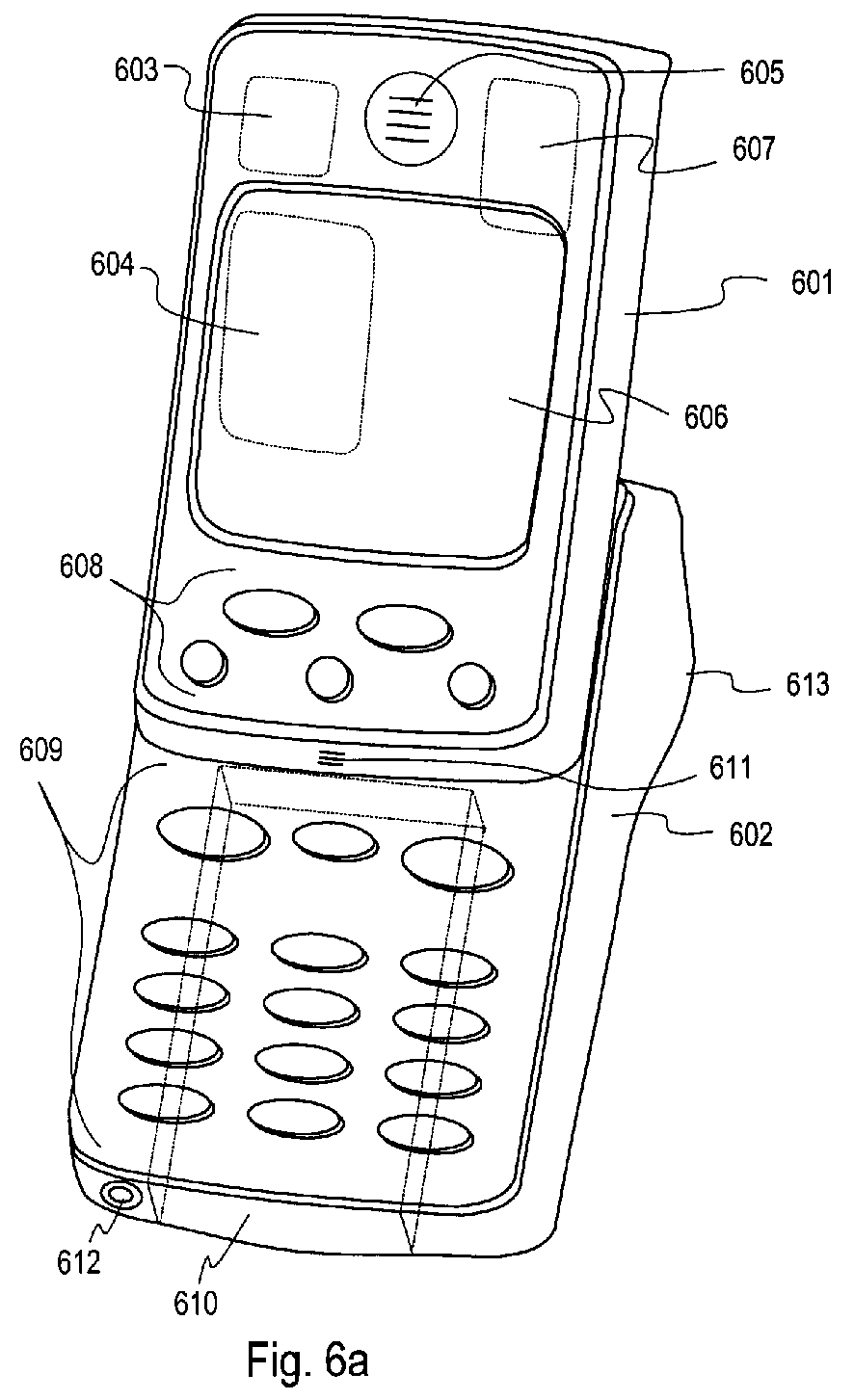
- Figure 6a is a schematical illustration of a mobile phone 600, including an upper part 601 and a lower part 602.
- the upper part 601 inside the shell, there is provided an antenna 603 for transmitting and receiving radio frequency messages, as well as a radio transmitter/receiver 604.
- the upper part 601 includes a loudspeaker 605, a microphone 611, a display 606, a smart card scanner 607 and a quick-action keyboard 608 including a few keys, advantageously provided with at least three and no more than ten keys; however, these numbers are not restrictive from the point of view of the invention.
- Typical keys of the quick-action keyboard 608 are the keys for starting and finishing a call, arrow keys or corresponding browsing keys and memory management keys.
- the quick-action keyboard 608 may also include a known multi-usage key, such as a Navi TM key.
- dotted lines are used to illustrate the contours of such parts that are not visible in the drawing, because they are located inside the telephone.
- the lower part 602 of the mobile phone illustrated in figure 6a comprises at least a number keyboard 609 and a battery 610. Moreover, at the edge of the lower part 602, there is connected a charging device 612.
- the number keyboard 609 includes at least the number keys from zero to nine.
- keys for controlling such operations that in a typical mobile phone usage are needed less frequently than the operations controlled by the keys of the quick-action keyboard 608, or which, for one reason or another, can only be used when the mobile phone is in the operating position.
- the sides of the lower part 602 of the mobile phone are designed so that a typical user gets a good grip thereof. In particular this means that the lower part is solid enough.
- the lower part may also be provided with particular grip designs 613, said designs being projections, recesses and/or non-slip features.
- Figure 6b illustrates the mobile phone of figure 6a in the transport position.
- the upper part 601 and the lower part 602 are sled, in relation to each other, so that they are located in an essentially overlapping fashion.
- the means for facilitating said sliding and locking in the position illustrated in figure 6b shall be described in more detail below.
- the keyboard remains in between the upper and the lower part and is not available for the user.
- the microphone 611 is not covered in the transport position, and thus the mobile phone 600 can be used as a telephone also in the position illustrated in figure 6b.
- the terms operating position and transport position must be understood as names of the positions illustrated in figures 6a and 6b only - they do not in any way restrict the usage or transportation of the mobile phone 600.
- a minimum requirement is that even in the transport position, the mobile phone must be able to exchange signalling messages connected to the idle mode of a normal cellular radio system terminal with a given base station.
- the microphone 611 could also be installed in the lower part, in which case it would in the operating position be located nearer to the user's mouth than in the structure illustrated in figures 6a and 6b. However, it would then be necessary to provide one lead connection more in between the upper and the lower part, in order to lead the signal from the microphone to the radio transmitter/receiver provided in the upper part.
- the lower part 602 functions as the voice conductor, conducting the user's speech to the microphone, when the user holds the telephone illustrated in the drawing in the operating position, at the side of his head. Simultaneously the lower part prevents interfering noise from elsewhere from directly entering the microphone.
- the essential point in the location of the microphone is that it should not in any normal, anticipated usage situation be pressed against the user's cheek, so that the voice could not reach the microphone.
- a mobile phone according to the invention can be further facilitated by providing it with a function according to which an incoming call can be answered simply by opening the telephone from the transport position to the operating position.
- the technical application for implementing this function could in principle be similar to the one provided in the known Nokia 8110 mobile phone manufactured by Nokia Mobile Phones; in structure this application corresponds to the one illustrated in figure 3, where it is sufficient to open the sliding lid in order to answer an incoming call.
- Figure 7a is a schematical illustration of a preferred embodiment as regards the means for realising the mutual slide function between the upper and the lower part.
- the lower part is provided with slide rails 701, and the upper part is provided with matching counter-rails 702.
- the lower part is provided with a spring 703 surrounded by a support tube 704.
- the upper part is provided with a piston 705, and the piston is designed and placed so that when the telephone according to the invention is sled to the transport position, the piston 705 is pressed to inside the support tube 704, and it presses the spring 703 together in the direction of the longitudinal axis thereof.
- the lower part includes a trigger 706 provided with a detent pin 707 that is matched to fit in the recess 708, provided in the upper part, when the mobile phone is in the transport position.
- the detent pin 707 slides out of the recess 708, so that the spring 703 pushes the mobile phone, by intermediation of the piston 705, to the operating position.
- the trigger 706 is advantageously arranged in connection with a grip design that is also otherwise natural for the user to hold. Such a grip design is for instance the bulge 613 illustrated in figure 6a.
- stoppers which stop the mutual motion between the upper and the lower part before the spring 703 has fully returned.
- the remaining compression of the spring 703 causes a strength in between the upper and the lower part, and this strength tries to maintain said parts in the operating position.
- a lock design connected to the trigger 706 or to another particularly designed trigger - or another known quick-release lock arrangement locks the upper and the lower part in the operating position.
- the material of the parts illustrated in figure 7a is mainly polyethene or polypropylene plastic or some other generally known polymer, and the parts can be formed by injection moulding or by another known method.
- the slide rails 701 and the counter-rails 702 at least one of these two are, however, advantageously made of metal or then they are metal-coated, because a drawback with plastic-plastic type slide parts is their high starting friction and the squeaking noise heard during the sliding. Longitudinal metal rails either in the upper or lower part also strengthen the mechanical structure of the telephone.
- FIG. 7b illustrates, by way of example, an attenuator composed of a gear wheel 709 rotatably attached to the upper part and of a housing 710 surrounding the axis of said gear wheel, as well as of a gear rack 711 attached to the lower part.
- the gear rack 711 rotates the gear wheel 709 and the axis connected thereto and surrounded by the housing 710.
- the housing 710 contains silicone oil, and the inertia caused by the moving of the oil tends to attenuate the rotating motion of the gear wheel 709. This attenuation is transmitted, via the gear wheel 709 and the gear rack 711, to the upper and the lower part, so that it softens the whole opening motion.
- FIG 8 is an exploded illustration of a keyboard module 800 according to a preferred embodiment of the invention; this module enables the realisation of the lower part of the above described mobile phone in a simple fashion which also is economical for the manufacturing technique.
- the electric core of the keyboard module is the circuit board 801, provided with contact pads for all elements to be electrically connected thereto, connector strips for the keys, known as such, and the required strip connectors for connecting the keys.
- the circuit board 801 can be a multilayer circuit board.
- the elements to be electrically connected thereto there are at least a slide connector 802 and a charging connector 803, as well as in a preferred embodiment of the invention, also a vibrating alarm 804 and an EL control 805 for controlling the electroluminescence illumination of the keyboard.
- the electrically connected elements are most advantageously fixed by soldering to the respective contact pads reserved for them; for the sake of graphical clarity, these pads are not illustrated in the drawing.
- the number keyboard is composed by connecting, in a known fashion, a film 806 including the contact pads on top of the connector strips provided in the circuit board 801 and by placing thereon an EL layer 807 which produces the electroluminescence display and a keypad 808 made of silicone or some other elastic material.
- the module composed of the above enlisted parts is attached to the shell element 809 by means of snap joints and/or screws. In the created module, there can be connected a battery 810 by means of a prior art quick-release locking mechanism.
- the invention does not require that the illuminated patterns of the keyboard are realised by using electroluminescence.
- An alternative is a prior art LED illumination, where the above mentioned EL control and EL film are replaced by a known LED control and LED illumination means.
- the upper part of the telephone (not illustrated in the drawing) is provided with a number of lead tracks on the surface that is placed against the lower part of the telephone.
- the mutual design and location of the slide connector 802 and the lead tracks is chosen so that irrespective of the fact whether the telephone is in the transport position or in the operating position or somewhere in between, each switch spring 811 of the upper surface of the slide connector touches its own lead track.
- each switch spring 811 of the upper surface of the slide connector slides, along its own lead track, in the lengthwise direction of said lead track.
- the slide connector 802 and the above mentioned lead tracks form an electric contact in between the upper and the lower parts of the telephone.
- the switch springs 811 of the slide connector are advantageously made elastic, in which case the location of the slide connector is chosen so that in a closed telephone, the switch springs 811 are continuously subjected to a slight compressing force. The counteractive force caused by this elasticity then holds each switch spring compactly pressed against the respective lead track.
- switch springs are illustrated on the top surface of the slide connector 802.
- the invention does not restrict the number of the switch springs nor the method by which they are used for transmitting various signals between the upper and the lower part of the telephone.
- the use of the switch springs conforms to the following table: Switch spring n:o Target of use 1 keyboard 2 keyboard ground 3 keyboard 4 Bsi (Battery size indicator) 5 ground 6 ground 7 BTmp (Battery Temperature) 8 keyboard lights 9 positive battery voltage 10 positive battery voltage 11 vibrating alarm 12 charging voltage
- the switch springs 812 provided at the side of the slide connector 802 are meant for forming a connection to the battery 810.
- the fastening of the battery is such that when fastened, it is pressed lightly against the switch springs 812, in which case the spring power improves the connection between the contact electrodes and the switch springs 812.
- the invention does not restrict the number or target of use of the switch springs provided at the side of the slide connector 812.
- the keyboard module is easy to manufacture owing to its compact structure. Moreover, the keyboard is easily detached and reattached in case it is somehow damaged or it should be replaced for some other reason.
- the achieved structure becomes fairly thin, which is advantageous with respect to the overall measures of the telephone.
- the battery 810 is narrower than the lower part of the telephone (cf. the battery illustrated by dotted lines in figure 6a), so that in the structure according to figure 8, on the other side of the battery there can be installed a charging connector 803, a vibrating alarm 804 and an EL control 805, and on the other side the protecting tube 704 illustrated in figure 7a and a spring 703 provided therein.
- the gear rack 711 may be installed in the upper part of the telephone and the gear wheel 709 and the housing 710 in the lower part thereof, and so forth.
- the trigger 706, which is preferably always placed in the lower part, because the idea is that during regular use, the user always holds the telephone in his hand by gripping the lower part.
- the microphone does not necessarily have to be a fixed installation, but it may be connected to the upper or the lower part for instance by intermediation of a similar turning arm as in the prior art telephone illustrated in figure 1.
- the display can be located lengthwise in the upper part, i.e. so that the direction of the horizontal dimension of the display is the same as the sliding direction of the above described upper part with respect to the lower part. In that case it may prove to be advantageous also to place the symbols connected to the keys so that they are easily figured out by the user when he holds the telephone "horizontally" in front of his eyes.
- the electric circuit controlling the display can also be arranged to function so that the user may choose whether he wants to use the display in the horizontal or in the vertical mode.
- the invention does not require that the motion between the upper and the lower part takes place by sliding, but it is possible to realise an embodiment where the upper and the lower part are interconnected by a hinge, in similar fashion as the housing and flap in the prior art telephone illustrated in figure 2.
- the sliding motion is considered preferable, because it is easier to control with one hand only.
- a spiral spring as the only elastic means that produces strength in between the upper and the lower part. It is, however, obvious that any equivalent for a spring can be used for the same purpose.
- the spiral spring can be a drawspring, so that in the transport position of the telephone, the drawspring is pulled tighter than in the operating position.
Abstract
Description
- This document has been filed as a European divisional application from a parent application number
06113106.6 99660046.6 - In general, the invention relates to the electric and mechanical structure of telephones. In particular, the invention relates to the structure of a telescopically expanding telephone and to the location of its elements. The term telephone here means any hand-held apparatus designed for radio communications and provided with a microphone and a loudspeaker. By way of example, we shall here discuss a mobile phone.
- Mobile phones are attempted to be made as small as possible in order to make them easily transportable in pockets or handbags. This tendency is, however, controversial to the feasibility of the telephone, because the user interface, i.e. mainly the keyboard and the display, must be made so small that on the display screen, there is room for limited information only (or the information must be shown on the screen with unreasonably small characters), and the keys and the spaces between them are unreasonably small for the fingers of an adult user. As a solution, there are suggested various folding telephones.
- Figures 1-4 illustrate various prior art solutions designed mainly in order to enlarge the user interface of a small-size telephone. The
mobile phone 100 illustrated in figure 1 comprises ahousing 101 and aturning arm 102 attached to the side of the housing by means of a rotating joint. Theloudspeaker 103 is provided in thehousing 101, and themicrophone 104 is located at the end of theturning arm 102. In preparation for use, theturning arm 102 is turned to a position illustrated by a uniform line in the drawing, and during transport it is turned to a position at the side of thehousing 101, illustrated by a dotted line. Themobile phone 200 illustrated in figure 2 comprises ahousing 201 and aflap 202 attached by a hinge at the bottom edge of the housing. In the transport position, theflap 202 covers thekeyboard 203, and in preparation for use, theflap 202 is turned to the position illustrated in figure 2, so that themicrophone 204 provided at the outer end of saidflap 202 comes near to the user's mouth in the regular usage position. The regular usage position means that the user holds the telephone in his hand, so that theloudspeaker 205 is pressed against his ear and theflap 202 points more or less towards his chin. - Figure 3 illustrates a
mobile phone 300 provided with a sliding lid, saidmobile phone 300 comprising ahousing 301 and alid 302 attached thereto by means of slide rails. In the transport position, thelid 302 completely covers thekeyboard 303. The usage position can be chosen according to how large a part of thekeys 303 the user needs. Figure 3 illustrates a usage position where thelid 302 is completely open. Themicrophone 304 is located in the bottom part of thelid 302, and theloudspeaker 305 is located in the top part of thehousing 301. The curved shape of thetelephone 300 helps to find a comfortable usage position where themicrophone 304 and theloudspeaker 305 are placed in a desired position with respect to the user's mouth and ear. The mobile phone illustrated in figure 3 can be called a telescopic telephone, because its length in the direction of a given (curved) dimension can be adjusted by sliding two mutually attached elements in relation to each other in the direction of said dimension. - In the applications illustrated in figures 1 - 3, the folding or sliding features of the telephone do not solve the problem connected to the size of the keyboard and display, but the emphasis has been to adjust the distance between the microphone and the loudspeaker.
- Figure 4 illustrates another known
telescopic telephone 400, which is introduced in theFinnish registered design application No. 285/97 housing 401 and an upper slidingpart 402 including aloudspeaker 403, adisplay 404 and a small part of thekeys 405. Thehousing 401 includes the rest of thekeys 406, amicrophone 407 and anantenna 408. For transporting the telephone, the upper slidingpart 402 can be sled on top of thehousing 401, so that thekeyboard 406 is covered. The functional practicality of this embodiment is dubious, because the antenna is easily left inside the user's hand, or very near to the user's hand, in which case it does not work in the best possible way. In order to realise a precise and versatile display in the embodiment of figure 4, there is needed a large amount of leads in between the housing and the upper sliding part, which is problematic with respect to the technical applications. Usually thedisplay 404 is provided with a glass plate or other such easily breakable part that requires a solid supporting structure around it; this requirement is difficult to fulfil in the embodiment according to figure 4. Moreover, there are shortcomings in the user ergonomics. - Figures 5a and 5b illustrate a known method for realising a large-size user interface. A multiple-use
mobile phone 500 comprises atop part 501 and abottom part 502, which are interconnected with a hinge. The outer surface of thetop part 501 constitutes a first user interface including a small-size display 503 and anumber keyboard 504. The inner surfaces of thetop part 501 and thebottom part 502 are shown by opening the telephone like a book, as is seen in figure 5b. The inner surfaces comprise another user interface provided with a large-size display and aletter keyboard 506. This application is not as such suited to the manufacturing of a mobile phone only, because in the position illustrated in figure 5b, theinstrument 500 cannot be held on the side of the head like a telephone. - The object of the present invention is to introduce a telephone which is, with respect to its mechanical structure, easy to use, durable and ergonomic.
- The objects of the invention are achieved by creating a spring force pushing a second part of the device in relation to a first part (601) from a first position towards a second position.
- The telephone according to the invention comprises a first part and a second part attached thereto, said second part being movable in relation to the first part between a first position and a second position. It is characterised by the features recited in the characterizing part of the independent claim.
- The mobile phone according to the invention comprises two parts that are sliding in relation to each other, and these parts are in the present application called upper part and lower part. Said terms refer to the mutual location of the parts in the appended drawings, and they do not restrict the manufacture, treatment or usage of the mobile phone of the invention with respect to any particular direction. The upper part is also called the first part of the telephone, and the lower part is respectively called the second part. The mutual movability of the upper and the lower part is realised in a sliding fashion, so that in the transport position, the upper and the lower part are located mainly in an overlapping fashion, and for operation they can be sled to a mutual position which is most comfortable for the user in each particular case.
- According to a preferred embodiment, the upper part of the telephone according to the invention comprises at least an antenna, a radio transmitter/receiver, a loudspeaker, a microphone and a display as well as part of the keys and a scanner for a smart card. The lower part comprises an arrangement for fastening a battery or a corresponding power source for the telephone, as well as the major part of the keys. The lower part is designed so that during operations, it is most natural for the user to hold the lower part of the telephone in his hand. Thus the antenna provided in the upper part is not left in the shadow of the user's hand, and not even very near to said hand. The battery attached to the lower part is a fairly heavy component, which improves the ergonomy of the telephone according to the invention in comparison with for example the telephone according to figure 3, where the lower part is very light. By installing the telephone components in the upper and the lower parts in an advantageous fashion, to be explained in more detail below, the number of electric contacts in between said parts is kept small, which is advantageous for usage security. In particularly, the invention enables the use of a relatively large display and keyboard even in a small mobile phone.
- An additional feature according to the invention is the lock and release mechanism based on spring power that is provided between the upper and the lower part, whereby the telephone can be adjusted from the transport position to the operating position by using one hand only. This is particularly advantageous because when a call comes in, the user must react fairly rapidly in order to answer the call, and he cannot always use both hands to do this. Other advantageous additional features are attenuation connected to the opening mechanism, and the realisation of the lower part keyboard as a module - provided, in addition to the keys, also with electric connections to the upper part, to the battery, to the charging device and to other possible electric components of the lower part.
- The invention is explained in more detail below, with reference to the preferred embodiments presented by way of example and to the appended drawings, where
- figure 1 illustrates a prior art mobile phone,
- figure 2 illustrates another prior art mobile phone,
- figure 3 illustrates a third prior art mobile phone,
- figure 4 illustrates a fourth prior art mobile phone,
- figure 5a illustrates a prior art mobile station,
- figure 5b illustrates the mobile station of figure 5a in another position,
- figure 6a illustrates a telephone of the invention in the operating position,
- figure 6b illustrates the telephone of figure 6a in the transport position,
- figure 7a illustrates a method for realising the motion between the upper and the lower part,
- figure 7b illustrates a method for attenuating the motion between the upper and the lower part, and
- figure 8 illustrates a keyboard module in a telephone according to the invention.
- In the above description of the prior art we already referred to figures 1-5, and in the specification of the invention and the preferred embodiments below, we shall mainly refer to figures 6a - 8. Like numbers for like parts are used in the drawings.
- Figure 6a is a schematical illustration of a
mobile phone 600, including anupper part 601 and alower part 602. In theupper part 601, inside the shell, there is provided anantenna 603 for transmitting and receiving radio frequency messages, as well as a radio transmitter/receiver 604. In addition, theupper part 601 includes aloudspeaker 605, amicrophone 611, adisplay 606, asmart card scanner 607 and a quick-action keyboard 608 including a few keys, advantageously provided with at least three and no more than ten keys; however, these numbers are not restrictive from the point of view of the invention. Typical keys of the quick-action keyboard 608 are the keys for starting and finishing a call, arrow keys or corresponding browsing keys and memory management keys. The quick-action keyboard 608 may also include a known multi-usage key, such as a Navi TM key. In figure 6a, dotted lines are used to illustrate the contours of such parts that are not visible in the drawing, because they are located inside the telephone. - The
lower part 602 of the mobile phone illustrated in figure 6a comprises at least anumber keyboard 609 and abattery 610. Moreover, at the edge of thelower part 602, there is connected acharging device 612. Advantageously thenumber keyboard 609 includes at least the number keys from zero to nine. In addition, there may be included keys for controlling such operations that in a typical mobile phone usage are needed less frequently than the operations controlled by the keys of the quick-action keyboard 608, or which, for one reason or another, can only be used when the mobile phone is in the operating position. The sides of thelower part 602 of the mobile phone are designed so that a typical user gets a good grip thereof. In particular this means that the lower part is solid enough. In order to help the user in getting a good grip and in order to appropriately focus the pressure caused by the grip, the lower part may also be provided with particular grip designs 613, said designs being projections, recesses and/or non-slip features. - Figure 6b illustrates the mobile phone of figure 6a in the transport position. The
upper part 601 and thelower part 602 are sled, in relation to each other, so that they are located in an essentially overlapping fashion. The means for facilitating said sliding and locking in the position illustrated in figure 6b shall be described in more detail below. In the transport position, the keyboard remains in between the upper and the lower part and is not available for the user. On the other hand, themicrophone 611 is not covered in the transport position, and thus themobile phone 600 can be used as a telephone also in the position illustrated in figure 6b. Here the terms operating position and transport position must be understood as names of the positions illustrated in figures 6a and 6b only - they do not in any way restrict the usage or transportation of themobile phone 600. A minimum requirement is that even in the transport position, the mobile phone must be able to exchange signalling messages connected to the idle mode of a normal cellular radio system terminal with a given base station. - The
microphone 611 could also be installed in the lower part, in which case it would in the operating position be located nearer to the user's mouth than in the structure illustrated in figures 6a and 6b. However, it would then be necessary to provide one lead connection more in between the upper and the lower part, in order to lead the signal from the microphone to the radio transmitter/receiver provided in the upper part. On the basis of figure 6a, it is easily seen how thelower part 602 functions as the voice conductor, conducting the user's speech to the microphone, when the user holds the telephone illustrated in the drawing in the operating position, at the side of his head. Simultaneously the lower part prevents interfering noise from elsewhere from directly entering the microphone. The essential point in the location of the microphone is that it should not in any normal, anticipated usage situation be pressed against the user's cheek, so that the voice could not reach the microphone. - The use of a mobile phone according to the invention can be further facilitated by providing it with a function according to which an incoming call can be answered simply by opening the telephone from the transport position to the operating position. The technical application for implementing this function could in principle be similar to the one provided in the known Nokia 8110 mobile phone manufactured by Nokia Mobile Phones; in structure this application corresponds to the one illustrated in figure 3, where it is sufficient to open the sliding lid in order to answer an incoming call.
- Figure 7a is a schematical illustration of a preferred embodiment as regards the means for realising the mutual slide function between the upper and the lower part.
- The lower part is provided with
slide rails 701, and the upper part is provided with matching counter-rails 702. In addition, the lower part is provided with aspring 703 surrounded by asupport tube 704. The upper part is provided with apiston 705, and the piston is designed and placed so that when the telephone according to the invention is sled to the transport position, thepiston 705 is pressed to inside thesupport tube 704, and it presses thespring 703 together in the direction of the longitudinal axis thereof. The lower part includes atrigger 706 provided with adetent pin 707 that is matched to fit in therecess 708, provided in the upper part, when the mobile phone is in the transport position. Thedetent pin 707 and therecess 708 together constitute a locking design, the purpose of which is to keep the mobile phone in the transport position, although the strength of thecompressed spring 703 tries to push thepiston 705 and thereby the whole upper part towards the operating position. When thetrigger 706 is now suitably moved, thedetent pin 707 slides out of therecess 708, so that thespring 703 pushes the mobile phone, by intermediation of thepiston 705, to the operating position. Thetrigger 706 is advantageously arranged in connection with a grip design that is also otherwise natural for the user to hold. Such a grip design is for instance thebulge 613 illustrated in figure 6a. - In the slide rails 701, and/or in the counter-rails 702, or in some other place in the mechanical structure of the apparatus, there are easily arranged stoppers which stop the mutual motion between the upper and the lower part before the
spring 703 has fully returned. Now in the operating position, the remaining compression of thespring 703 causes a strength in between the upper and the lower part, and this strength tries to maintain said parts in the operating position. There can also be presented an embodiment where a lock design connected to thetrigger 706 or to another particularly designed trigger - or another known quick-release lock arrangement - locks the upper and the lower part in the operating position. - Advantageously the material of the parts illustrated in figure 7a is mainly polyethene or polypropylene plastic or some other generally known polymer, and the parts can be formed by injection moulding or by another known method. As regards the slide rails 701 and the counter-rails 702, at least one of these two are, however, advantageously made of metal or then they are metal-coated, because a drawback with plastic-plastic type slide parts is their high starting friction and the squeaking noise heard during the sliding. Longitudinal metal rails either in the upper or lower part also strengthen the mechanical structure of the telephone.
- If the
spring 703, as the only factor affecting the motional speed, can freely adjust the opening of the mobile phone according to the invention from the transport position to the operating position, the opening motion easily becomes too sudden and vigorous. From the point of view of usage comfort, it is advantageous to use an attenuator for softening the opening motion. The invention does not restrict the type of the attenuator employed. Figure 7b illustrates, by way of example, an attenuator composed of agear wheel 709 rotatably attached to the upper part and of ahousing 710 surrounding the axis of said gear wheel, as well as of agear rack 711 attached to the lower part. These are mutually arranged so that always when the upper and the lower part move in relation to each other, thegear rack 711 rotates thegear wheel 709 and the axis connected thereto and surrounded by thehousing 710. In order to attenuate the motion, thehousing 710 contains silicone oil, and the inertia caused by the moving of the oil tends to attenuate the rotating motion of thegear wheel 709. This attenuation is transmitted, via thegear wheel 709 and thegear rack 711, to the upper and the lower part, so that it softens the whole opening motion. - Figure 8 is an exploded illustration of a
keyboard module 800 according to a preferred embodiment of the invention; this module enables the realisation of the lower part of the above described mobile phone in a simple fashion which also is economical for the manufacturing technique. The electric core of the keyboard module is thecircuit board 801, provided with contact pads for all elements to be electrically connected thereto, connector strips for the keys, known as such, and the required strip connectors for connecting the keys. If necessary, thecircuit board 801 can be a multilayer circuit board. Among the elements to be electrically connected thereto, there are at least aslide connector 802 and a chargingconnector 803, as well as in a preferred embodiment of the invention, also a vibratingalarm 804 and anEL control 805 for controlling the electroluminescence illumination of the keyboard. The electrically connected elements are most advantageously fixed by soldering to the respective contact pads reserved for them; for the sake of graphical clarity, these pads are not illustrated in the drawing. The number keyboard is composed by connecting, in a known fashion, afilm 806 including the contact pads on top of the connector strips provided in thecircuit board 801 and by placing thereon anEL layer 807 which produces the electroluminescence display and akeypad 808 made of silicone or some other elastic material. The module composed of the above enlisted parts is attached to theshell element 809 by means of snap joints and/or screws. In the created module, there can be connected abattery 810 by means of a prior art quick-release locking mechanism. - The invention does not require that the illuminated patterns of the keyboard are realised by using electroluminescence. An alternative is a prior art LED illumination, where the above mentioned EL control and EL film are replaced by a known LED control and LED illumination means.
- As a counterpart for the
slide connector 802, the upper part of the telephone (not illustrated in the drawing) is provided with a number of lead tracks on the surface that is placed against the lower part of the telephone. The mutual design and location of theslide connector 802 and the lead tracks is chosen so that irrespective of the fact whether the telephone is in the transport position or in the operating position or somewhere in between, eachswitch spring 811 of the upper surface of the slide connector touches its own lead track. In other words, when sliding the upper and the lower parts of the telephone in relation to each other, eachswitch spring 811 of the upper surface of the slide connector slides, along its own lead track, in the lengthwise direction of said lead track. Theslide connector 802 and the above mentioned lead tracks form an electric contact in between the upper and the lower parts of the telephone. The switch springs 811 of the slide connector are advantageously made elastic, in which case the location of the slide connector is chosen so that in a closed telephone, the switch springs 811 are continuously subjected to a slight compressing force. The counteractive force caused by this elasticity then holds each switch spring compactly pressed against the respective lead track. - In figure 8, 12 switch springs are illustrated on the top surface of the
slide connector 802. The invention does not restrict the number of the switch springs nor the method by which they are used for transmitting various signals between the upper and the lower part of the telephone. In order to improve operational security, it is advisable to use a minimum of two separate switch springs for transmitting at least the service voltage and ground potential. According to a preferred embodiment, the use of the switch springs conforms to the following table:Switch spring n:o Target of use 1 keyboard 2 keyboard ground 3 keyboard 4 Bsi (Battery size indicator) 5 ground 6 ground 7 BTmp (Battery Temperature) 8 keyboard lights 9 positive battery voltage 10 positive battery voltage 11 vibrating alarm 12 charging voltage - The switch springs 812 provided at the side of the
slide connector 802 are meant for forming a connection to thebattery 810. Most advantageously the fastening of the battery is such that when fastened, it is pressed lightly against the switch springs 812, in which case the spring power improves the connection between the contact electrodes and the switch springs 812. The invention does not restrict the number or target of use of the switch springs provided at the side of theslide connector 812. - The keyboard module is easy to manufacture owing to its compact structure. Moreover, the keyboard is easily detached and reattached in case it is somehow damaged or it should be replaced for some other reason. The achieved structure becomes fairly thin, which is advantageous with respect to the overall measures of the telephone. In a structure according to a preferred embodiment, the
battery 810 is narrower than the lower part of the telephone (cf. the battery illustrated by dotted lines in figure 6a), so that in the structure according to figure 8, on the other side of the battery there can be installed a chargingconnector 803, a vibratingalarm 804 and anEL control 805, and on the other side the protectingtube 704 illustrated in figure 7a and aspring 703 provided therein. - Obviously the above described embodiments are presented by way of example only, and they do not restrict the invention. For example, most of the mechanical parts illustrated in figures 7a and 7b can be moved from one part of the telephone to another, the
gear rack 711 may be installed in the upper part of the telephone and thegear wheel 709 and thehousing 710 in the lower part thereof, and so forth. An exception is thetrigger 706, which is preferably always placed in the lower part, because the idea is that during regular use, the user always holds the telephone in his hand by gripping the lower part. The microphone does not necessarily have to be a fixed installation, but it may be connected to the upper or the lower part for instance by intermediation of a similar turning arm as in the prior art telephone illustrated in figure 1. If there is desired a display where the horizontal dimension is larger than the vertical dimension, the display can be located lengthwise in the upper part, i.e. so that the direction of the horizontal dimension of the display is the same as the sliding direction of the above described upper part with respect to the lower part. In that case it may prove to be advantageous also to place the symbols connected to the keys so that they are easily figured out by the user when he holds the telephone "horizontally" in front of his eyes. The electric circuit controlling the display can also be arranged to function so that the user may choose whether he wants to use the display in the horizontal or in the vertical mode. - The invention does not require that the motion between the upper and the lower part takes place by sliding, but it is possible to realise an embodiment where the upper and the lower part are interconnected by a hinge, in similar fashion as the housing and flap in the prior art telephone illustrated in figure 2. However, the sliding motion is considered preferable, because it is easier to control with one hand only. In the above specification we have suggested the use of a spiral spring as the only elastic means that produces strength in between the upper and the lower part. It is, however, obvious that any equivalent for a spring can be used for the same purpose. Instead of the above described compression spring, the spiral spring can be a drawspring, so that in the transport position of the telephone, the drawspring is pulled tighter than in the operating position.
Claims (11)
- A portable telephone apparatus comprising a first part (601) and a second part (602) attached thereto, said second part being movable in relation to the first part between a first position and a second position, wherein the first part comprises a display (606), a radio transmitter/receiver (604) and a connected antenna (605), and the second part comprises a number keyboard (609) and an arrangement for attaching a battery (610) to the second part, characterised in that the first part comprises a quick-action keyboard (608), and that the portable telephone apparatus comprises a spring (703) adapted to produce a spring force pushing the second part in relation to the first part (601) from the first position towards the second position.
- A telephone according to claim 1, characterised in that the second part (602) is slidably movable in relation to the first part (601) in between the first and the second position, for which function the second part comprises slide rails (701) and the first part comprises matching counter-rails (702).
- A telephone according to claim 2, characterised in that said first part (601) and second part (602) are in the first position located in an essentially overlapping fashion.
- A telephone according to claim 1, characterised in that said spring (703) has a drawn position and a released position, so that the first position of the second part corresponds to the drawn position of the spring, and the second position of the second part corresponds to the released position of the spring.
- A telephone according to claim4, characterised in that it comprises a trigger mechanism (706, 707, 708) in order to lock the second part in the position where said spring is drawn, and
in order to release the locked second part by means of user action. - A telephone according to claim5, characterised in that it comprises a mechanical attenuator (709, 710, 711) for attenuating the mutual motion between the first and the second part while the second part moves in relation to the first part under the influence of the strength created by said spring.
- A telephone according to claim 6, characterised in that said attenuator comprises a gear wheel (709) and a gear rack (711) arranged in functional interaction with it, said gear wheel and gear rack being located one in the first part of the telephone and the other in the second part thereof, as well as an attenuating member (710) for attenuating the rotating motion of said gear wheel.
- A telephone according to claim 1, characterised in that the second part is rotatably movable with respect to the first part in between the first and the second position, for which function the telephone is provided with a hinge in between the first and the second part.
- A telephone according to claim 1, characterised in that it comprises in the second part a grip design (613) for getting a grip of the second part with one hand.
- A telephone according to claim 1, characterised in that it comprises means for receiving an incoming call by adjusting said first part from the first position to the second position.
- A telephone according to claim 1, characterised in that it is a mobile phone in a digital cellular network.
Priority Applications (1)
| Application Number | Priority Date | Filing Date | Title |
|---|---|---|---|
| EP10182064.5A EP2264984B1 (en) | 1998-03-18 | 1999-03-16 | Telescopic telephone |
Applications Claiming Priority (3)
| Application Number | Priority Date | Filing Date | Title |
|---|---|---|---|
| FI980602A FI112759B (en) | 1998-03-18 | 1998-03-18 | Phone Telescope |
| EP99660046A EP0944219B1 (en) | 1998-03-18 | 1999-03-16 | Telescopic telephone |
| EP06113106A EP1679861A1 (en) | 1998-03-18 | 1999-03-16 | Foldable telephone |
Related Parent Applications (3)
| Application Number | Title | Priority Date | Filing Date |
|---|---|---|---|
| EP99660046.6 Division | 1999-03-16 | ||
| EP06113106A Division EP1679861A1 (en) | 1998-03-18 | 1999-03-16 | Foldable telephone |
| EP06113106.6 Division | 2006-04-26 |
Related Child Applications (1)
| Application Number | Title | Priority Date | Filing Date |
|---|---|---|---|
| EP10182064.5 Division-Into | 2010-09-29 |
Publications (3)
| Publication Number | Publication Date |
|---|---|
| EP1833231A2 true EP1833231A2 (en) | 2007-09-12 |
| EP1833231A3 EP1833231A3 (en) | 2007-12-12 |
| EP1833231B1 EP1833231B1 (en) | 2012-07-04 |
Family
ID=8551309
Family Applications (4)
| Application Number | Title | Priority Date | Filing Date |
|---|---|---|---|
| EP10182064.5A Expired - Lifetime EP2264984B1 (en) | 1998-03-18 | 1999-03-16 | Telescopic telephone |
| EP99660046A Expired - Lifetime EP0944219B1 (en) | 1998-03-18 | 1999-03-16 | Telescopic telephone |
| EP07111051A Expired - Lifetime EP1833231B1 (en) | 1998-03-18 | 1999-03-16 | Telescopic telephone |
| EP06113106A Withdrawn EP1679861A1 (en) | 1998-03-18 | 1999-03-16 | Foldable telephone |
Family Applications Before (2)
| Application Number | Title | Priority Date | Filing Date |
|---|---|---|---|
| EP10182064.5A Expired - Lifetime EP2264984B1 (en) | 1998-03-18 | 1999-03-16 | Telescopic telephone |
| EP99660046A Expired - Lifetime EP0944219B1 (en) | 1998-03-18 | 1999-03-16 | Telescopic telephone |
Family Applications After (1)
| Application Number | Title | Priority Date | Filing Date |
|---|---|---|---|
| EP06113106A Withdrawn EP1679861A1 (en) | 1998-03-18 | 1999-03-16 | Foldable telephone |
Country Status (8)
| Country | Link |
|---|---|
| US (2) | US6961593B1 (en) |
| EP (4) | EP2264984B1 (en) |
| JP (2) | JPH11331332A (en) |
| AT (1) | ATE333187T1 (en) |
| DE (1) | DE69932276T2 (en) |
| ES (1) | ES2268844T3 (en) |
| FI (1) | FI112759B (en) |
| PT (1) | PT1833231E (en) |
Families Citing this family (86)
| Publication number | Priority date | Publication date | Assignee | Title |
|---|---|---|---|---|
| FI112759B (en) | 1998-03-18 | 2003-12-31 | Nokia Corp | Phone Telescope |
| JP4298054B2 (en) * | 1999-04-23 | 2009-07-15 | パナソニック株式会社 | Portable wireless device |
| US6542721B2 (en) * | 1999-10-11 | 2003-04-01 | Peter V. Boesen | Cellular telephone, personal digital assistant and pager unit |
| FR2802046B1 (en) * | 1999-12-01 | 2002-04-19 | Sagem | WIRELESS TELEPHONE SET WITH INTEGRATED ANTENNA AND SLIDING KEYBOARD |
| US7224373B1 (en) * | 2000-04-07 | 2007-05-29 | Danger, Inc. | Adjustable data processing display |
| FI112422B (en) | 2000-04-28 | 2003-11-28 | Nokia Corp | Telescopic structure for telephone equipment |
| KR100454485B1 (en) * | 2000-08-18 | 2004-10-28 | 삼성전자주식회사 | Longitudinally extendable cellular phone |
| US8332553B2 (en) | 2000-09-21 | 2012-12-11 | Hewlett-Packard Development Company, L.P. | Method and apparatus for accessing a contacts database and telephone services |
| WO2002030090A1 (en) * | 2000-10-02 | 2002-04-11 | Nokia Corporation | Sliding cover |
| GB2371437A (en) * | 2001-01-22 | 2002-07-24 | Nokia Mobile Phones Ltd | Wearable mobile phone with detachable extendible section |
| US8239531B1 (en) | 2001-07-23 | 2012-08-07 | At&T Intellectual Property Ii, L.P. | Method and apparatus for connection to virtual private networks for secure transactions |
| US7692667B2 (en) * | 2001-08-17 | 2010-04-06 | Palm, Inc. | Handheld computer having moveable segments that are interactive with an integrated display |
| CA2408331C (en) | 2001-10-16 | 2008-11-18 | Research In Motion Limited | Handheld mobile communication device with repositionable display and inputs |
| JP2003298699A (en) * | 2002-03-29 | 2003-10-17 | Nec Corp | Slide-type portable telephone set |
| JP2003319042A (en) * | 2002-04-25 | 2003-11-07 | Matsushita Electric Ind Co Ltd | Portable terminal device |
| US20040204000A1 (en) * | 2002-05-30 | 2004-10-14 | Aaron Dietrich | Mobile communication device including an array sensor |
| GB2395085B (en) * | 2002-11-04 | 2006-09-06 | Agere Systems Ltd | Electronic apparatus |
| KR100484732B1 (en) | 2002-11-19 | 2005-04-22 | 삼성전자주식회사 | Sliding type portable wireless terminal |
| DE10258183B3 (en) * | 2002-12-12 | 2004-07-29 | Siemens Ag | Slider mobile phone with flexible shaft loudspeaker |
| JP3962322B2 (en) * | 2002-12-26 | 2007-08-22 | 松下電器産業株式会社 | Portable electronic devices |
| DE10314311A1 (en) * | 2003-03-31 | 2004-10-28 | Siemens Ag | mobile device |
| US7295852B1 (en) | 2003-05-01 | 2007-11-13 | Palm, Inc. | Automated telephone conferencing method and system |
| US7865180B2 (en) | 2003-06-23 | 2011-01-04 | Palm, Inc. | Automated telephone conferencing method and system |
| KR100531880B1 (en) * | 2003-07-10 | 2005-11-29 | 엘지전자 주식회사 | Sliding device in sliding type mobile phone |
| KR100536939B1 (en) * | 2003-07-11 | 2005-12-19 | 엘지전자 주식회사 | Slide type portable terminal |
| JP4519441B2 (en) | 2003-10-17 | 2010-08-04 | パナソニック株式会社 | Mobile terminal device |
| KR100606108B1 (en) * | 2003-10-31 | 2006-07-28 | 삼성전자주식회사 | Swing-type portable digital telephone and swing hinge device thereof |
| US7532915B2 (en) | 2003-11-03 | 2009-05-12 | Agere Systems Inc. | Electronic apparatus having three modes of operation |
| KR100617690B1 (en) * | 2003-11-10 | 2006-08-28 | 삼성전자주식회사 | Sliding type portable wireless terminal |
| KR100608727B1 (en) | 2003-12-09 | 2006-08-04 | 엘지전자 주식회사 | Separable mobile phone for display communication and communication method thereof |
| US7106260B2 (en) * | 2004-02-17 | 2006-09-12 | Samsung Electronics Co., Ltd. | Antenna device for portable wireless terminal |
| JP2005277737A (en) * | 2004-03-24 | 2005-10-06 | Hitachi Ltd | Portable electronic equipment with camera |
| WO2005101799A1 (en) * | 2004-04-12 | 2005-10-27 | Advanex Inc. | Slide unit for portable product and portable product |
| KR100704031B1 (en) * | 2004-04-29 | 2007-04-04 | 삼성전자주식회사 | Double sliding-type portable communication device |
| KR100663552B1 (en) * | 2004-06-10 | 2007-01-02 | 삼성전자주식회사 | Portable terminal with movable keypad |
| KR100595674B1 (en) * | 2004-06-22 | 2006-07-03 | 엘지전자 주식회사 | Slide apparatus for slide type mobile phone |
| KR100616197B1 (en) * | 2004-08-24 | 2006-08-25 | 삼성전자주식회사 | Sliding apparatus for double sliding-type portable communication device |
| JP4169204B2 (en) * | 2004-09-16 | 2008-10-22 | ソニー・エリクソン・モバイルコミュニケーションズ株式会社 | Mobile terminal device |
| KR100648471B1 (en) | 2004-10-08 | 2006-11-28 | 삼성전자주식회사 | Sim/uim card arrangement in slide type portable wireless terminal |
| JP4344887B2 (en) * | 2004-10-13 | 2009-10-14 | 株式会社カシオ日立モバイルコミュニケーションズ | Portable information terminal |
| KR101050634B1 (en) * | 2004-11-10 | 2011-07-19 | 삼성전자주식회사 | Antenna device of portable terminal |
| TWI249324B (en) * | 2004-11-19 | 2006-02-11 | Benq Corp | Sliding-type electronic device with a view angle |
| KR100617673B1 (en) * | 2004-12-06 | 2006-08-28 | 삼성전자주식회사 | Sliding module for sliding type mobile phone and sliding type mobile phone employing the same |
| US7671836B2 (en) | 2005-01-03 | 2010-03-02 | Nokia Corporation | Cell phone with shiftable keypad |
| US20060176660A1 (en) * | 2005-02-07 | 2006-08-10 | Ahmad Amiri | Ultra mobile communicating computer |
| KR100689468B1 (en) * | 2005-03-21 | 2007-03-08 | 삼성전자주식회사 | Sliding/swing type mobile phone |
| US7447528B2 (en) | 2005-04-12 | 2008-11-04 | Nokia Corporation | Multifunction electronic device |
| US7520436B2 (en) * | 2005-04-18 | 2009-04-21 | Samsung Electronics Co., Ltd | Slide module for slide type portable terminal and cover apparatus for external type card mounted thereto |
| TWI260152B (en) * | 2005-05-12 | 2006-08-11 | Benq Corp | Ergonomic mobile device |
| KR100675179B1 (en) * | 2005-05-16 | 2007-01-30 | 엘지전자 주식회사 | Scroll type input apparatus for mobile communication terminal |
| JP4613096B2 (en) * | 2005-05-17 | 2011-01-12 | パナソニック株式会社 | Portable radio |
| KR20070008946A (en) * | 2005-07-14 | 2007-01-18 | 삼성전자주식회사 | Display device and portable wireless terminal having the same |
| WO2007018146A1 (en) * | 2005-08-05 | 2007-02-15 | Matsushita Electric Industrial Co., Ltd. | Portable terminal device |
| US20070080947A1 (en) * | 2005-10-06 | 2007-04-12 | Rau James M | Bartender's buddy |
| US20070082697A1 (en) | 2005-10-07 | 2007-04-12 | Research In Motion Limited | System and method of handset configuration between cellular and private wireless network modes |
| TWI278216B (en) * | 2005-11-03 | 2007-04-01 | Benq Corp | Mobile device |
| KR100761480B1 (en) * | 2006-05-26 | 2007-09-27 | 삼성전자주식회사 | Portable electric device and camera |
| US8089776B2 (en) * | 2006-06-19 | 2012-01-03 | Sony Ericsson Mobile Communications Ab | Side switch for a contact exposed on an edge of a circuit board and method |
| TW200803416A (en) * | 2006-06-30 | 2008-01-01 | Inventec Corp | Portable electronic system |
| KR101266248B1 (en) * | 2006-08-07 | 2013-05-22 | 삼성디스플레이 주식회사 | Display Device, Method of Manufacturing The Same And Mobile Communication Terminal Having The Same |
| JP5199597B2 (en) | 2006-11-14 | 2013-05-15 | パナソニック株式会社 | Slide-type mobile terminal |
| WO2008059894A1 (en) * | 2006-11-14 | 2008-05-22 | Panasonic Corporation | Sliding portable terminal |
| DE602007004469D1 (en) | 2007-07-04 | 2010-03-11 | Research In Motion Ltd | Antenna spacer for a portable communication device |
| US8639302B2 (en) | 2007-07-04 | 2014-01-28 | Blackberry Limited | Antenna spacer for a handheld communication device |
| JP4470971B2 (en) * | 2007-08-07 | 2010-06-02 | 株式会社デンソー | Portable machine |
| TW200909700A (en) * | 2007-08-17 | 2009-03-01 | Asustek Comp Inc | Foldable electronic device |
| US8126519B2 (en) | 2007-08-31 | 2012-02-28 | Hewlett-Packard Development Company, L.P. | Housing for mobile computing device having construction to slide and pivot into multiple positions |
| TW200917929A (en) * | 2007-10-05 | 2009-04-16 | Qisda Corp | Bilateral sliding module and the electronic device for using the same |
| US8233948B2 (en) | 2007-12-11 | 2012-07-31 | Hewlett-Packard Development Company, L.P. | Slider assembly for a housing of a mobile computing device |
| US8150482B2 (en) | 2008-01-08 | 2012-04-03 | Hewlett-Packard Development Company, L.P. | Mobile computing device with moveable housing segments |
| US8121659B2 (en) * | 2007-12-20 | 2012-02-21 | Nokia Corporation | Slide mechanism |
| US8200298B2 (en) | 2008-01-08 | 2012-06-12 | Hewlett-Packard Development Company, L.P. | Keypad housing configuration for a mobile computing device |
| USD611018S1 (en) * | 2008-09-24 | 2010-03-02 | Samsung Electronics Co., Ltd. | Portable telephone |
| US8451179B2 (en) * | 2008-10-29 | 2013-05-28 | Hewlett-Packard Development Company, L.P. | Sliding antenna apparatus |
| CN101742859A (en) * | 2008-11-20 | 2010-06-16 | 深圳富泰宏精密工业有限公司 | Portable electronic device |
| JP5317180B2 (en) * | 2008-11-25 | 2013-10-16 | 日本電気株式会社 | Flexible printed circuit board mounting structure and sliding electronic device |
| JP2011004332A (en) * | 2009-06-22 | 2011-01-06 | Fujitsu Component Ltd | Slide hinge, and portable electronic apparatus |
| TWM388826U (en) * | 2010-04-30 | 2010-09-11 | Hon Hai Prec Ind Co Ltd | Sliding apparatus |
| TW201207585A (en) * | 2010-08-05 | 2012-02-16 | Chi Mei Comm Systems Inc | Mobile electronic device rocking system and method thereof |
| TWM461245U (en) * | 2013-04-25 | 2013-09-01 | Hon Hai Prec Ind Co Ltd | Charger |
| US9143865B2 (en) * | 2013-05-21 | 2015-09-22 | Htc Corporation | Handheld electronic devices and methods involving distributed mode loudspeakers |
| US9560179B2 (en) * | 2013-07-05 | 2017-01-31 | John Ashmore LUMBARD | Foldable curved wireless communication device for insertion into hip pocket |
| US20150011262A1 (en) | 2013-07-05 | 2015-01-08 | John Ashmore LUMBARD | Mobile, Handheld Wireless Communication Device, Smartphone, With Improved Functionality |
| US10079923B2 (en) | 2013-07-05 | 2018-09-18 | John Ashmore LUMBARD | Foldable electronic gaming or mobile communication device for insertion into hip pocket |
| US9705551B2 (en) | 2014-04-04 | 2017-07-11 | Jason Gaines | Stable communication cover |
| EP4191372A4 (en) * | 2020-11-06 | 2024-01-10 | Samsung Electronics Co Ltd | Electronic device including flexible display and antenna |
Citations (6)
| Publication number | Priority date | Publication date | Assignee | Title |
|---|---|---|---|---|
| EP0414365A2 (en) | 1989-08-24 | 1991-02-27 | Nokia Mobile Phones (U.K.) Limited | Portable radio telephone |
| US5260998A (en) | 1990-09-07 | 1993-11-09 | Fujitsu Limited | Folding portable telephone set |
| EP0631416A2 (en) | 1993-06-28 | 1994-12-28 | Nec Corporation | Foldable portable telephone set |
| DE29618839U1 (en) | 1996-10-29 | 1996-12-19 | Siemens Ag | Cellular device |
| US5636275A (en) | 1995-03-31 | 1997-06-03 | Fujitsu Limited | Hinge mechanism and foldable portable telephone having the hinge mechanism |
| EP0944219A2 (en) | 1998-03-18 | 1999-09-22 | Nokia Mobile Phones Ltd. | Telescopic telephone |
Family Cites Families (40)
| Publication number | Priority date | Publication date | Assignee | Title |
|---|---|---|---|---|
| FI285A (en) | 1887-06-20 | Formed bottles and bottoms of sailors | ||
| DE3323858A1 (en) * | 1983-07-01 | 1985-01-03 | Erwin Brandenstein | Cordless telephone device |
| EP0445808B1 (en) * | 1990-03-07 | 1994-11-23 | Sony Corporation | Radio telephone apparatus |
| JP3016889B2 (en) | 1991-02-28 | 2000-03-06 | 日本電気株式会社 | Mobile phone |
| CA2100448C (en) * | 1991-11-29 | 1996-11-12 | Jeffery F. Kurgan | Apparatus for accepting and retaining a smart card |
| US5170173A (en) | 1992-04-27 | 1992-12-08 | Motorola, Inc. | Antenna coupling apparatus for cordless telephone |
| JP3074944B2 (en) * | 1992-07-20 | 2000-08-07 | 日本電気株式会社 | Mobile phone |
| US5363089A (en) * | 1992-09-24 | 1994-11-08 | Motorola, Inc. | Electronic device having multi-position hinged mechanism |
| US5907615A (en) * | 1992-12-02 | 1999-05-25 | Motorola, Inc. | Miniature wireless communication device |
| JPH06284067A (en) * | 1993-03-30 | 1994-10-07 | Toshiba Corp | Portable radio telephone set |
| US5981189A (en) * | 1993-05-14 | 1999-11-09 | Chan; Voon Loong | Hippuricase gene |
| US5440629A (en) * | 1993-07-02 | 1995-08-08 | Gray; Robert R. | Changeable contour construction of wireless telephone |
| US5485517A (en) | 1993-12-07 | 1996-01-16 | Gray; Robert R. | Portable wireless telephone having swivel chassis |
| EP0658030B1 (en) | 1993-12-09 | 2003-06-11 | Nec Corporation | Foldable portable radiotelephone |
| JP2595932B2 (en) * | 1994-05-18 | 1997-04-02 | 日本電気株式会社 | Portable radio |
| JP2658935B2 (en) * | 1994-12-30 | 1997-09-30 | 日本電気株式会社 | Electronic device having hinge structure |
| JP3375019B2 (en) * | 1995-01-01 | 2003-02-10 | 株式会社リコス | Portable wireless telephone |
| DE19520947C5 (en) * | 1995-06-02 | 2012-04-05 | Constin Design Gmbh | Portable computer with telecommunication device |
| US5797089A (en) | 1995-09-07 | 1998-08-18 | Telefonaktiebolaget Lm Ericsson (Publ) | Personal communications terminal having switches which independently energize a mobile telephone and a personal digital assistant |
| US6018671A (en) * | 1995-12-29 | 2000-01-25 | Motorola, Inc. | Silent call accept |
| JPH09205384A (en) * | 1996-01-29 | 1997-08-05 | Nec Corp | Portable radio equipment |
| JP2000506323A (en) * | 1996-02-26 | 2000-05-23 | ノキア モービル フォーンズ リミテッド | Wireless phone |
| GB2310560B (en) * | 1996-02-26 | 2000-07-12 | Nokia Mobile Phones Ltd | A radio telephone |
| US6046730A (en) * | 1996-03-15 | 2000-04-04 | At&T Corp | Backlighting scheme for a multimedia terminal keypad |
| JPH1065784A (en) * | 1996-04-17 | 1998-03-06 | Lucent Technol Inc | Portable telephone equipment with movable key pad |
| JP3606498B2 (en) * | 1996-04-26 | 2005-01-05 | 三菱電機株式会社 | Portable information terminal device |
| SE9601701L (en) * | 1996-05-03 | 1997-11-04 | Ericsson Telefon Ab L M | Audio Conductor for Speech Communicators |
| US5835006A (en) | 1996-05-22 | 1998-11-10 | Moorola, Inc. | Vibrator assembly |
| US5918189A (en) * | 1996-09-30 | 1999-06-29 | Nokia Mobile Phones, Ltd. | Exchangeable hardware module for radiotelephone |
| US6128514A (en) * | 1997-01-31 | 2000-10-03 | Bellsouth Corporation | Portable radiotelephone for automatically dialing a central voice-activated dialing system |
| JP3988199B2 (en) * | 1997-02-26 | 2007-10-10 | ソニー株式会社 | Telephone |
| US6128475A (en) * | 1997-04-04 | 2000-10-03 | Sony Corporation | Wireless telephone with sliding keyboard |
| US6002946A (en) * | 1997-04-14 | 1999-12-14 | Motorola, Inc. | Handheld device having an optical data reader |
| US6011699A (en) * | 1997-10-15 | 2000-01-04 | Motorola, Inc. | Electronic device including apparatus and method for routing flexible circuit conductors |
| US6038313A (en) * | 1997-11-20 | 2000-03-14 | Nortel Networks Corporation | Double sided keyboard for a telephone |
| US6064734A (en) * | 1997-11-21 | 2000-05-16 | Sony Corporation Of Japan | Telephone with sliding keypad |
| US6118986A (en) * | 1998-01-16 | 2000-09-12 | Motorola, Inc. | Device for use with a user interface card |
| US6151486A (en) * | 1998-10-30 | 2000-11-21 | Ericsson Inc. | Magnetic latch and release device and radiotelephones incorporating same |
| US6208874B1 (en) * | 1998-11-02 | 2001-03-27 | Ericsson Inc. | Telephone assembly with automatic antenna adjustment |
| FI20000931A (en) * | 2000-04-18 | 2001-10-19 | Nokia Mobile Phones Ltd | Portable electronic device |
-
1998
- 1998-03-18 FI FI980602A patent/FI112759B/en not_active IP Right Cessation
-
1999
- 1999-03-12 US US09/268,080 patent/US6961593B1/en not_active Expired - Lifetime
- 1999-03-16 PT PT07111051T patent/PT1833231E/en unknown
- 1999-03-16 EP EP10182064.5A patent/EP2264984B1/en not_active Expired - Lifetime
- 1999-03-16 DE DE69932276T patent/DE69932276T2/en not_active Expired - Lifetime
- 1999-03-16 EP EP99660046A patent/EP0944219B1/en not_active Expired - Lifetime
- 1999-03-16 EP EP07111051A patent/EP1833231B1/en not_active Expired - Lifetime
- 1999-03-16 AT AT99660046T patent/ATE333187T1/en not_active IP Right Cessation
- 1999-03-16 ES ES99660046T patent/ES2268844T3/en not_active Expired - Lifetime
- 1999-03-16 EP EP06113106A patent/EP1679861A1/en not_active Withdrawn
- 1999-03-18 JP JP11074157A patent/JPH11331332A/en active Pending
-
2005
- 2005-07-06 US US11/175,710 patent/US7519404B2/en not_active Expired - Fee Related
-
2008
- 2008-12-04 JP JP2008309547A patent/JP4746668B2/en not_active Expired - Fee Related
Patent Citations (7)
| Publication number | Priority date | Publication date | Assignee | Title |
|---|---|---|---|---|
| EP0414365A2 (en) | 1989-08-24 | 1991-02-27 | Nokia Mobile Phones (U.K.) Limited | Portable radio telephone |
| US5260998A (en) | 1990-09-07 | 1993-11-09 | Fujitsu Limited | Folding portable telephone set |
| EP0631416A2 (en) | 1993-06-28 | 1994-12-28 | Nec Corporation | Foldable portable telephone set |
| US5636275A (en) | 1995-03-31 | 1997-06-03 | Fujitsu Limited | Hinge mechanism and foldable portable telephone having the hinge mechanism |
| DE29618839U1 (en) | 1996-10-29 | 1996-12-19 | Siemens Ag | Cellular device |
| EP0944219A2 (en) | 1998-03-18 | 1999-09-22 | Nokia Mobile Phones Ltd. | Telescopic telephone |
| EP1679861A1 (en) | 1998-03-18 | 2006-07-12 | Nokia Corporation | Foldable telephone |
Also Published As
| Publication number | Publication date |
|---|---|
| EP0944219A3 (en) | 2003-08-06 |
| US20050265545A1 (en) | 2005-12-01 |
| PT1833231E (en) | 2012-08-07 |
| US6961593B1 (en) | 2005-11-01 |
| FI980602A0 (en) | 1998-03-18 |
| EP1679861A1 (en) | 2006-07-12 |
| DE69932276D1 (en) | 2006-08-24 |
| EP1833231B1 (en) | 2012-07-04 |
| JP2009081882A (en) | 2009-04-16 |
| EP2264984B1 (en) | 2013-07-24 |
| EP0944219B1 (en) | 2006-07-12 |
| JP4746668B2 (en) | 2011-08-10 |
| FI980602A (en) | 1999-09-19 |
| DE69932276T2 (en) | 2007-06-14 |
| EP1833231A3 (en) | 2007-12-12 |
| ES2268844T3 (en) | 2007-03-16 |
| FI112759B (en) | 2003-12-31 |
| ATE333187T1 (en) | 2006-08-15 |
| EP2264984A1 (en) | 2010-12-22 |
| EP0944219A2 (en) | 1999-09-22 |
| US7519404B2 (en) | 2009-04-14 |
| JPH11331332A (en) | 1999-11-30 |
Similar Documents
| Publication | Publication Date | Title |
|---|---|---|
| EP1833231B1 (en) | Telescopic telephone | |
| KR100810314B1 (en) | Key input apparatus for portable communication device | |
| US8155718B2 (en) | Sliding/hinge apparatus for sliding/rotating type mobile terminals | |
| EP1531604B1 (en) | Sliding/hinge apparatus for sliding/rotating type mobile terminals | |
| EP1610531B1 (en) | Method of Operating a Radio Telephone | |
| KR100313144B1 (en) | Watch type portable radiotelephone | |
| US5640689A (en) | Communications apparatus with antenna switching based on antenna rotation | |
| WO1999043134A1 (en) | Hinge assemblies for electronic devices | |
| GB2330032A (en) | Radio communication device having a retractable keyboard | |
| EP2223511A1 (en) | Slide mechanism | |
| US20040142719A1 (en) | Mobile communication device | |
| EP1860850A2 (en) | Mobile phone having decoration cover used as key input means | |
| JP2004235687A (en) | Portable radio terminal | |
| WO2003030497A2 (en) | Portable communication terminal a slidable keypad | |
| KR100312546B1 (en) | Folder-type cellular phone in which cover including display at its external surface is glidingly opened and closed | |
| US8009064B2 (en) | Data input device for portable terminal | |
| KR100325246B1 (en) | Hinge device with automatic switching unit in flip-type portable telephone | |
| KR20060057272A (en) | Portable terminal with 2-way key on outer surface of folder | |
| KR20010026579A (en) | Digital camera phone | |
| KR20060097233A (en) | Sliding keypad apparatus for mobile phone |
Legal Events
| Date | Code | Title | Description |
|---|---|---|---|
| PUAI | Public reference made under article 153(3) epc to a published international application that has entered the european phase |
Free format text: ORIGINAL CODE: 0009012 |
|
| AC | Divisional application: reference to earlier application |
Ref document number: 1679861 Country of ref document: EP Kind code of ref document: P Ref document number: 0944219 Country of ref document: EP Kind code of ref document: P |
|
| AK | Designated contracting states |
Kind code of ref document: A2 Designated state(s): AT BE CH CY DE DK ES FI FR GB GR IE IT LI LU MC NL PT SE |
|
| PUAL | Search report despatched |
Free format text: ORIGINAL CODE: 0009013 |
|
| RIN1 | Information on inventor provided before grant (corrected) |
Inventor name: LONKA, PEKKA Inventor name: KONTKANEN, MIKAEL |
|
| AK | Designated contracting states |
Kind code of ref document: A3 Designated state(s): AT BE CH CY DE DK ES FI FR GB GR IE IT LI LU MC NL PT SE |
|
| RIC1 | Information provided on ipc code assigned before grant |
Ipc: H04M 1/02 20060101AFI20070802BHEP Ipc: H01Q 1/24 20060101ALI20071106BHEP |
|
| 17P | Request for examination filed |
Effective date: 20080425 |
|
| 17Q | First examination report despatched |
Effective date: 20080627 |
|
| AKX | Designation fees paid |
Designated state(s): AT BE CH CY DE DK ES FI FR GB GR IE IT LI LU MC NL PT SE |
|
| GRAP | Despatch of communication of intention to grant a patent |
Free format text: ORIGINAL CODE: EPIDOSNIGR1 |
|
| GRAS | Grant fee paid |
Free format text: ORIGINAL CODE: EPIDOSNIGR3 |
|
| GRAA | (expected) grant |
Free format text: ORIGINAL CODE: 0009210 |
|
| AC | Divisional application: reference to earlier application |
Ref document number: 1679861 Country of ref document: EP Kind code of ref document: P Ref document number: 0944219 Country of ref document: EP Kind code of ref document: P |
|
| AK | Designated contracting states |
Kind code of ref document: B1 Designated state(s): AT BE CH CY DE DK ES FI FR GB GR IE IT LI LU MC NL PT SE |
|
| REG | Reference to a national code |
Ref country code: GB Ref legal event code: FG4D |
|
| REG | Reference to a national code |
Ref country code: DE Ref legal event code: R081 Ref document number: 69944293 Country of ref document: DE Owner name: NOKIA TECHNOLOGIES OY, FI Free format text: FORMER OWNER: NOKIA CORP., 02610 ESPOO, FI |
|
| REG | Reference to a national code |
Ref country code: CH Ref legal event code: EP |
|
| REG | Reference to a national code |
Ref country code: AT Ref legal event code: REF Ref document number: 565524 Country of ref document: AT Kind code of ref document: T Effective date: 20120715 |
|
| REG | Reference to a national code |
Ref country code: IE Ref legal event code: FG4D |
|
| REG | Reference to a national code |
Ref country code: PT Ref legal event code: SC4A Free format text: AVAILABILITY OF NATIONAL TRANSLATION Effective date: 20120801 |
|
| REG | Reference to a national code |
Ref country code: NL Ref legal event code: T3 |
|
| REG | Reference to a national code |
Ref country code: DE Ref legal event code: R096 Ref document number: 69944293 Country of ref document: DE Effective date: 20120830 |
|
| REG | Reference to a national code |
Ref country code: AT Ref legal event code: MK05 Ref document number: 565524 Country of ref document: AT Kind code of ref document: T Effective date: 20120704 |
|
| PG25 | Lapsed in a contracting state [announced via postgrant information from national office to epo] |
Ref country code: BE Free format text: LAPSE BECAUSE OF FAILURE TO SUBMIT A TRANSLATION OF THE DESCRIPTION OR TO PAY THE FEE WITHIN THE PRESCRIBED TIME-LIMIT Effective date: 20120704 Ref country code: AT Free format text: LAPSE BECAUSE OF FAILURE TO SUBMIT A TRANSLATION OF THE DESCRIPTION OR TO PAY THE FEE WITHIN THE PRESCRIBED TIME-LIMIT Effective date: 20120704 Ref country code: FI Free format text: LAPSE BECAUSE OF FAILURE TO SUBMIT A TRANSLATION OF THE DESCRIPTION OR TO PAY THE FEE WITHIN THE PRESCRIBED TIME-LIMIT Effective date: 20120704 Ref country code: CY Free format text: LAPSE BECAUSE OF FAILURE TO SUBMIT A TRANSLATION OF THE DESCRIPTION OR TO PAY THE FEE WITHIN THE PRESCRIBED TIME-LIMIT Effective date: 20120704 |
|
| PG25 | Lapsed in a contracting state [announced via postgrant information from national office to epo] |
Ref country code: SE Free format text: LAPSE BECAUSE OF FAILURE TO SUBMIT A TRANSLATION OF THE DESCRIPTION OR TO PAY THE FEE WITHIN THE PRESCRIBED TIME-LIMIT Effective date: 20120704 Ref country code: GR Free format text: LAPSE BECAUSE OF FAILURE TO SUBMIT A TRANSLATION OF THE DESCRIPTION OR TO PAY THE FEE WITHIN THE PRESCRIBED TIME-LIMIT Effective date: 20121005 |
|
| PG25 | Lapsed in a contracting state [announced via postgrant information from national office to epo] |
Ref country code: ES Free format text: LAPSE BECAUSE OF FAILURE TO SUBMIT A TRANSLATION OF THE DESCRIPTION OR TO PAY THE FEE WITHIN THE PRESCRIBED TIME-LIMIT Effective date: 20121015 Ref country code: DK Free format text: LAPSE BECAUSE OF FAILURE TO SUBMIT A TRANSLATION OF THE DESCRIPTION OR TO PAY THE FEE WITHIN THE PRESCRIBED TIME-LIMIT Effective date: 20120704 |
|
| PLBE | No opposition filed within time limit |
Free format text: ORIGINAL CODE: 0009261 |
|
| STAA | Information on the status of an ep patent application or granted ep patent |
Free format text: STATUS: NO OPPOSITION FILED WITHIN TIME LIMIT |
|
| PG25 | Lapsed in a contracting state [announced via postgrant information from national office to epo] |
Ref country code: IT Free format text: LAPSE BECAUSE OF FAILURE TO SUBMIT A TRANSLATION OF THE DESCRIPTION OR TO PAY THE FEE WITHIN THE PRESCRIBED TIME-LIMIT Effective date: 20120704 |
|
| 26N | No opposition filed |
Effective date: 20130405 |
|
| REG | Reference to a national code |
Ref country code: DE Ref legal event code: R097 Ref document number: 69944293 Country of ref document: DE Effective date: 20130405 |
|
| PG25 | Lapsed in a contracting state [announced via postgrant information from national office to epo] |
Ref country code: MC Free format text: LAPSE BECAUSE OF NON-PAYMENT OF DUE FEES Effective date: 20130331 |
|
| REG | Reference to a national code |
Ref country code: CH Ref legal event code: PL |
|
| GBPC | Gb: european patent ceased through non-payment of renewal fee |
Effective date: 20130316 |
|
| REG | Reference to a national code |
Ref country code: FR Ref legal event code: ST Effective date: 20131129 |
|
| PG25 | Lapsed in a contracting state [announced via postgrant information from national office to epo] |
Ref country code: GB Free format text: LAPSE BECAUSE OF NON-PAYMENT OF DUE FEES Effective date: 20130316 Ref country code: CH Free format text: LAPSE BECAUSE OF NON-PAYMENT OF DUE FEES Effective date: 20130331 Ref country code: FR Free format text: LAPSE BECAUSE OF NON-PAYMENT OF DUE FEES Effective date: 20130402 Ref country code: LI Free format text: LAPSE BECAUSE OF NON-PAYMENT OF DUE FEES Effective date: 20130331 |
|
| PGFP | Annual fee paid to national office [announced via postgrant information from national office to epo] |
Ref country code: PT Payment date: 20150316 Year of fee payment: 17 Ref country code: IE Payment date: 20150309 Year of fee payment: 17 |
|
| PG25 | Lapsed in a contracting state [announced via postgrant information from national office to epo] |
Ref country code: LU Free format text: LAPSE BECAUSE OF NON-PAYMENT OF DUE FEES Effective date: 20130316 |
|
| REG | Reference to a national code |
Ref country code: DE Ref legal event code: R081 Ref document number: 69944293 Country of ref document: DE Owner name: NOKIA TECHNOLOGIES OY, FI Free format text: FORMER OWNER: NOKIA CORPORATION, ESPOO, FI Ref country code: DE Ref legal event code: R081 Ref document number: 69944293 Country of ref document: DE Owner name: NOKIA TECHNOLOGIES OY, FI Free format text: FORMER OWNER: NOKIA CORPORATION, 02610 ESPOO, FI |
|
| REG | Reference to a national code |
Ref country code: PT Ref legal event code: PC4A Owner name: NOKIA TECHNOLOGIES OY, FI Effective date: 20151127 |
|
| REG | Reference to a national code |
Ref country code: NL Ref legal event code: PD Owner name: NOKIA TECHNOLOGIES OY; FI Free format text: DETAILS ASSIGNMENT: VERANDERING VAN EIGENAAR(S), OVERDRACHT; FORMER OWNER NAME: NOKIA CORPORATION Effective date: 20151111 |
|
| PGFP | Annual fee paid to national office [announced via postgrant information from national office to epo] |
Ref country code: NL Payment date: 20160310 Year of fee payment: 18 Ref country code: DE Payment date: 20160308 Year of fee payment: 18 |
|
| PG25 | Lapsed in a contracting state [announced via postgrant information from national office to epo] |
Ref country code: PT Free format text: LAPSE BECAUSE OF NON-PAYMENT OF DUE FEES Effective date: 20160916 |
|
| REG | Reference to a national code |
Ref country code: IE Ref legal event code: MM4A |
|
| PG25 | Lapsed in a contracting state [announced via postgrant information from national office to epo] |
Ref country code: IE Free format text: LAPSE BECAUSE OF NON-PAYMENT OF DUE FEES Effective date: 20160316 |
|
| REG | Reference to a national code |
Ref country code: DE Ref legal event code: R119 Ref document number: 69944293 Country of ref document: DE |
|
| REG | Reference to a national code |
Ref country code: NL Ref legal event code: MM Effective date: 20170401 |
|
| PG25 | Lapsed in a contracting state [announced via postgrant information from national office to epo] |
Ref country code: NL Free format text: LAPSE BECAUSE OF NON-PAYMENT OF DUE FEES Effective date: 20170401 Ref country code: DE Free format text: LAPSE BECAUSE OF NON-PAYMENT OF DUE FEES Effective date: 20171003 |