EP1834364B1 - Method and apparatus for controlling the vaporization of organic material - Google Patents
Method and apparatus for controlling the vaporization of organic material Download PDFInfo
- Publication number
- EP1834364B1 EP1834364B1 EP05818811A EP05818811A EP1834364B1 EP 1834364 B1 EP1834364 B1 EP 1834364B1 EP 05818811 A EP05818811 A EP 05818811A EP 05818811 A EP05818811 A EP 05818811A EP 1834364 B1 EP1834364 B1 EP 1834364B1
- Authority
- EP
- European Patent Office
- Prior art keywords
- organic material
- manifold
- vaporization
- temperature
- vaporized
- Prior art date
- Legal status (The legal status is an assumption and is not a legal conclusion. Google has not performed a legal analysis and makes no representation as to the accuracy of the status listed.)
- Active
Links
- 239000011368 organic material Substances 0.000 title claims abstract description 180
- 238000000034 method Methods 0.000 title claims abstract description 26
- 238000009834 vaporization Methods 0.000 title claims description 84
- 230000008016 vaporization Effects 0.000 title claims description 83
- 238000010438 heat treatment Methods 0.000 claims abstract description 77
- 239000000758 substrate Substances 0.000 claims abstract description 61
- 230000008021 deposition Effects 0.000 claims abstract description 37
- 239000000463 material Substances 0.000 claims description 35
- 230000005855 radiation Effects 0.000 claims description 6
- 238000001816 cooling Methods 0.000 claims description 3
- 238000000151 deposition Methods 0.000 description 35
- 238000005297 material degradation process Methods 0.000 description 9
- 239000012159 carrier gas Substances 0.000 description 8
- 238000009833 condensation Methods 0.000 description 7
- 230000005494 condensation Effects 0.000 description 7
- 239000011261 inert gas Substances 0.000 description 6
- 239000011248 coating agent Substances 0.000 description 5
- 238000000576 coating method Methods 0.000 description 5
- 238000013459 approach Methods 0.000 description 4
- 230000015556 catabolic process Effects 0.000 description 4
- 238000006731 degradation reaction Methods 0.000 description 4
- 239000010410 layer Substances 0.000 description 4
- 238000005240 physical vapour deposition Methods 0.000 description 4
- 239000000843 powder Substances 0.000 description 4
- 230000003247 decreasing effect Effects 0.000 description 3
- 230000001419 dependent effect Effects 0.000 description 3
- 239000010408 film Substances 0.000 description 3
- 239000007789 gas Substances 0.000 description 3
- IJGRMHOSHXDMSA-UHFFFAOYSA-N Atomic nitrogen Chemical compound N#N IJGRMHOSHXDMSA-UHFFFAOYSA-N 0.000 description 2
- 230000001934 delay Effects 0.000 description 2
- 238000009826 distribution Methods 0.000 description 2
- 230000006698 induction Effects 0.000 description 2
- 239000007787 solid Substances 0.000 description 2
- 239000010409 thin film Substances 0.000 description 2
- 238000007740 vapor deposition Methods 0.000 description 2
- 239000011364 vaporized material Substances 0.000 description 2
- 239000000919 ceramic Substances 0.000 description 1
- 238000011109 contamination Methods 0.000 description 1
- 238000010924 continuous production Methods 0.000 description 1
- 230000000593 degrading effect Effects 0.000 description 1
- 238000005137 deposition process Methods 0.000 description 1
- 230000001627 detrimental effect Effects 0.000 description 1
- 230000000694 effects Effects 0.000 description 1
- 238000001704 evaporation Methods 0.000 description 1
- 239000012530 fluid Substances 0.000 description 1
- 229910010272 inorganic material Inorganic materials 0.000 description 1
- 239000011147 inorganic material Substances 0.000 description 1
- 210000003041 ligament Anatomy 0.000 description 1
- 239000007788 liquid Substances 0.000 description 1
- 230000007774 longterm Effects 0.000 description 1
- 238000004519 manufacturing process Methods 0.000 description 1
- 239000002184 metal Substances 0.000 description 1
- 229910052751 metal Inorganic materials 0.000 description 1
- 150000002739 metals Chemical class 0.000 description 1
- 239000000203 mixture Substances 0.000 description 1
- 229910052757 nitrogen Inorganic materials 0.000 description 1
- 239000012044 organic layer Substances 0.000 description 1
- 239000011236 particulate material Substances 0.000 description 1
- 239000002243 precursor Substances 0.000 description 1
- 239000010453 quartz Substances 0.000 description 1
- 239000003507 refrigerant Substances 0.000 description 1
- VYPSYNLAJGMNEJ-UHFFFAOYSA-N silicon dioxide Inorganic materials O=[Si]=O VYPSYNLAJGMNEJ-UHFFFAOYSA-N 0.000 description 1
- 150000003384 small molecules Chemical class 0.000 description 1
Images


Classifications
-
- C—CHEMISTRY; METALLURGY
- C23—COATING METALLIC MATERIAL; COATING MATERIAL WITH METALLIC MATERIAL; CHEMICAL SURFACE TREATMENT; DIFFUSION TREATMENT OF METALLIC MATERIAL; COATING BY VACUUM EVAPORATION, BY SPUTTERING, BY ION IMPLANTATION OR BY CHEMICAL VAPOUR DEPOSITION, IN GENERAL; INHIBITING CORROSION OF METALLIC MATERIAL OR INCRUSTATION IN GENERAL
- C23C—COATING METALLIC MATERIAL; COATING MATERIAL WITH METALLIC MATERIAL; SURFACE TREATMENT OF METALLIC MATERIAL BY DIFFUSION INTO THE SURFACE, BY CHEMICAL CONVERSION OR SUBSTITUTION; COATING BY VACUUM EVAPORATION, BY SPUTTERING, BY ION IMPLANTATION OR BY CHEMICAL VAPOUR DEPOSITION, IN GENERAL
- C23C14/00—Coating by vacuum evaporation, by sputtering or by ion implantation of the coating forming material
- C23C14/22—Coating by vacuum evaporation, by sputtering or by ion implantation of the coating forming material characterised by the process of coating
- C23C14/54—Controlling or regulating the coating process
- C23C14/542—Controlling the film thickness or evaporation rate
- C23C14/543—Controlling the film thickness or evaporation rate using measurement on the vapor source
-
- C—CHEMISTRY; METALLURGY
- C23—COATING METALLIC MATERIAL; COATING MATERIAL WITH METALLIC MATERIAL; CHEMICAL SURFACE TREATMENT; DIFFUSION TREATMENT OF METALLIC MATERIAL; COATING BY VACUUM EVAPORATION, BY SPUTTERING, BY ION IMPLANTATION OR BY CHEMICAL VAPOUR DEPOSITION, IN GENERAL; INHIBITING CORROSION OF METALLIC MATERIAL OR INCRUSTATION IN GENERAL
- C23C—COATING METALLIC MATERIAL; COATING MATERIAL WITH METALLIC MATERIAL; SURFACE TREATMENT OF METALLIC MATERIAL BY DIFFUSION INTO THE SURFACE, BY CHEMICAL CONVERSION OR SUBSTITUTION; COATING BY VACUUM EVAPORATION, BY SPUTTERING, BY ION IMPLANTATION OR BY CHEMICAL VAPOUR DEPOSITION, IN GENERAL
- C23C14/00—Coating by vacuum evaporation, by sputtering or by ion implantation of the coating forming material
- C23C14/22—Coating by vacuum evaporation, by sputtering or by ion implantation of the coating forming material characterised by the process of coating
- C23C14/54—Controlling or regulating the coating process
- C23C14/542—Controlling the film thickness or evaporation rate
-
- C—CHEMISTRY; METALLURGY
- C23—COATING METALLIC MATERIAL; COATING MATERIAL WITH METALLIC MATERIAL; CHEMICAL SURFACE TREATMENT; DIFFUSION TREATMENT OF METALLIC MATERIAL; COATING BY VACUUM EVAPORATION, BY SPUTTERING, BY ION IMPLANTATION OR BY CHEMICAL VAPOUR DEPOSITION, IN GENERAL; INHIBITING CORROSION OF METALLIC MATERIAL OR INCRUSTATION IN GENERAL
- C23C—COATING METALLIC MATERIAL; COATING MATERIAL WITH METALLIC MATERIAL; SURFACE TREATMENT OF METALLIC MATERIAL BY DIFFUSION INTO THE SURFACE, BY CHEMICAL CONVERSION OR SUBSTITUTION; COATING BY VACUUM EVAPORATION, BY SPUTTERING, BY ION IMPLANTATION OR BY CHEMICAL VAPOUR DEPOSITION, IN GENERAL
- C23C14/00—Coating by vacuum evaporation, by sputtering or by ion implantation of the coating forming material
- C23C14/06—Coating by vacuum evaporation, by sputtering or by ion implantation of the coating forming material characterised by the coating material
- C23C14/12—Organic material
-
- C—CHEMISTRY; METALLURGY
- C23—COATING METALLIC MATERIAL; COATING MATERIAL WITH METALLIC MATERIAL; CHEMICAL SURFACE TREATMENT; DIFFUSION TREATMENT OF METALLIC MATERIAL; COATING BY VACUUM EVAPORATION, BY SPUTTERING, BY ION IMPLANTATION OR BY CHEMICAL VAPOUR DEPOSITION, IN GENERAL; INHIBITING CORROSION OF METALLIC MATERIAL OR INCRUSTATION IN GENERAL
- C23C—COATING METALLIC MATERIAL; COATING MATERIAL WITH METALLIC MATERIAL; SURFACE TREATMENT OF METALLIC MATERIAL BY DIFFUSION INTO THE SURFACE, BY CHEMICAL CONVERSION OR SUBSTITUTION; COATING BY VACUUM EVAPORATION, BY SPUTTERING, BY ION IMPLANTATION OR BY CHEMICAL VAPOUR DEPOSITION, IN GENERAL
- C23C14/00—Coating by vacuum evaporation, by sputtering or by ion implantation of the coating forming material
- C23C14/22—Coating by vacuum evaporation, by sputtering or by ion implantation of the coating forming material characterised by the process of coating
- C23C14/24—Vacuum evaporation
- C23C14/246—Replenishment of source material
-
- C—CHEMISTRY; METALLURGY
- C23—COATING METALLIC MATERIAL; COATING MATERIAL WITH METALLIC MATERIAL; CHEMICAL SURFACE TREATMENT; DIFFUSION TREATMENT OF METALLIC MATERIAL; COATING BY VACUUM EVAPORATION, BY SPUTTERING, BY ION IMPLANTATION OR BY CHEMICAL VAPOUR DEPOSITION, IN GENERAL; INHIBITING CORROSION OF METALLIC MATERIAL OR INCRUSTATION IN GENERAL
- C23C—COATING METALLIC MATERIAL; COATING MATERIAL WITH METALLIC MATERIAL; SURFACE TREATMENT OF METALLIC MATERIAL BY DIFFUSION INTO THE SURFACE, BY CHEMICAL CONVERSION OR SUBSTITUTION; COATING BY VACUUM EVAPORATION, BY SPUTTERING, BY ION IMPLANTATION OR BY CHEMICAL VAPOUR DEPOSITION, IN GENERAL
- C23C14/00—Coating by vacuum evaporation, by sputtering or by ion implantation of the coating forming material
- C23C14/22—Coating by vacuum evaporation, by sputtering or by ion implantation of the coating forming material characterised by the process of coating
- C23C14/24—Vacuum evaporation
- C23C14/26—Vacuum evaporation by resistance or inductive heating of the source
-
- H—ELECTRICITY
- H10—SEMICONDUCTOR DEVICES; ELECTRIC SOLID-STATE DEVICES NOT OTHERWISE PROVIDED FOR
- H10K—ORGANIC ELECTRIC SOLID-STATE DEVICES
- H10K71/00—Manufacture or treatment specially adapted for the organic devices covered by this subclass
- H10K71/10—Deposition of organic active material
- H10K71/16—Deposition of organic active material using physical vapour deposition [PVD], e.g. vacuum deposition or sputtering
- H10K71/164—Deposition of organic active material using physical vapour deposition [PVD], e.g. vacuum deposition or sputtering using vacuum deposition
Definitions
- the present invention relates to the field of physical vapor deposition where a source material is heated to a temperature so as to cause vaporization and create a vapor plume to form a thin film on a surface of a substrate.
- the organic materials used in OLED devices have a highly nonlinear dependence of vaporization rate on source temperature. A small change in source temperature leads to a very large change in vaporization rate.
- prior art devices employ source temperature as the only way to control vaporization rate.
- prior art deposition sources typically utilize heating structures whose solid volume is much larger than the organic charge volume, composed of high thermal-conductivity materials that are well insulated. The high thermal conductivity insures good temperature uniformity through the structure and the large thermal mass helps to maintain the temperature within a critically small range by reducing temperature fluctuations. These measures have the desired effect on steady-state vaporization rate stability but have a detrimental effect at start-up. It is common that these devices must operate for long periods of time (e.g.
- the current method to minimize material time at high temperature and to maximize machine operation time by minimizing the start-up and cool-down times of the material-containing sources requires using duplicate sources of the same material sequentially. For example, rather than using one source continuously for eight days, two sources can be used for four days each or eight sources can be used in a serial process for one day each by overlapping the start-up and cool-down times. Duplicate sources, however, increase equipment size and cost, especially if the number of duplicate sources or the number of materials that require duplicate sources is large.
- Forrest et al. U.S. Patent No. 6,337,102 B1 disclose a method for vaporizing organic materials and organic precursors and delivering them to a reactor vessel wherein the substrate is situated, and delivery of the vapors generated from solids or liquids is accomplished by use of carrier gases.
- the organic materials are held at a constant temperature that is high enough to saturate the incoming carrier gas at all possible flow rates. Deposition rate is controlled by adjusting the carrier-gas flow rate.
- Forrest et al. locate the substrates within a suitably large reactor vessel, and the vapors carried thereto mix and react or condense on the substrate.
- Forrest et al. disclose the use of a gas curtain fed by a gas manifold (defined in the disclosure as "hollow tubes having a line of holes") in order to form a continuous line of depositing material perpendicular to the direction of substrate travel..
- Furukawa et al. in Japanese Unexamined Patent Application 9-219289 , disclose a method of forming an organic thin-film electroluminescent element by a flash vapor deposition method. While this method can start and stop quickly, it cannot be run as a continuous process as taught by Furukawa et al.
- the organic material is dropped onto a heated plate.
- Furakawa is silent on the nature of the powder delivery system, and how it assures that the desired quantity of powder is actually dropped on the heated plate, and therefore how vaporization rate, the deposited film thickness, and thickness uniformity are controlled. Also unclear is how the powder delivery system, with a temperature below the condensation temperature of the just-created vapor, is prevented from acting as a cold finger upon which a portion of the just-created vapor condenses.
- VanSlyke et al "Linear Source Deposition of Organic Layers for Full-Color OLED", 2002 SID Inter. Symposium Digest of Technical Papers, pages 886-889 discloses a method and apparatus for evaporating organic material.
- a volume of organic powder is placed in a quartz boat, vaporized organic material asses by a baffle and exits a manifold with at least one aperture.
- the organic material is heated by a bottom heater below the vaporization temperature and a top heater to raise the temperature sufficiently to vaporize the upper surface of the organic material.
- EP 1130129 also discloses a thermal physical vapor deposition structure having a boat with a source. A manifold is also provided through which vaporized material passes.
- WO 2005/083146 provides two heating regions a first heating region maintaining the organic material below the vaporization temperature and a second heating region above the vaporization temperature of the organic material and provides metering of the organic material at a controlled rate from the first region to the second region.
- WO 2006/034019A2 and WO2006/034028 considered as intermediate prior art disclose methods for delivering particulate material to a vaporization zone, the material being transferred to an auger.
- the device overcomes the heating and volume limitations of prior art devices in that only a small portion of organic material is heated to the desired rate-dependent vaporization temperature at a controlled rate. It is therefore a feature of the present invention to maintain a steady vaporization rate with a large charge of organic material and with a steady heater temperature.
- the device permits extended operation of the source with substantially reduced risk of degrading even very temperature-sensitive organic materials.
- This feature additionally permits materials having different vaporization rates and degradation temperature thresholds to be co-sublimated in the same source. This feature additionally permits short material-reloading times due to the low thermal mass of the heated material.
- the present device achieves substantially higher vaporization rates than in prior art devices without material degradation. Further still, no heater temperature change is required as the source material is consumed.
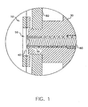
- FIG. 1 there is shown a cross-sectional view of an apparatus for controlling the deposition of vaporized organic material onto a substrate surface by controlling the vaporization of organic material in a vaporization source onto a substrate surface in accordance with this invention.
- Apparatus 10 is a vaporization source and includes an initial volume of organic material 20 and a metering device 60 for advancing organic material 20 in a controlled manner from first temperature-controlled region 30 to second temperature-controlled region 50.
- Metering device 60 can be e.g. an auger screw or a similar auger structure. Such metering device, and a way of providing a volume of organic material to them, have previously been described by Long et al.
- First temperature-controlled region 30 can be a region of high thermal mass, e.g. a large base, and can include such materials as metals and ceramics to maintain organic material 20 at a desired temperature below its vaporization temperature.
- First temperature-controlled region 30 can be heated or cooled as needed and includes a first heating device, which can be any well-known heating device, e.g. heating coil, induction heating, heating/cooling tubes, and the like. The first heating device is not shown for clarity.
- First temperature-controlled region 30 is heated to and maintained below the vaporization temperature of organic material 20.
- the vaporization temperature is defined as the lowest temperature wherein the vapor pressure of organic material 20 is sufficient to effectively form a layer of organic material on a substrate. By effectively we mean at a practical manufacturing rate. Because the vapor pressure of a material is a continuous function with respect to temperature, at any non-zero absolute temperature, the material has a non-zero vapor pressure.
- the above definition of vaporization temperature is useful for describing operating conditions and relative temperatures of various regions within a practical deposition device.
- condensation temperature At a given partial pressure of material, the material vapor will condense onto a surface held at or below a measurable temperature. This temperature is defined as the condensation temperature and depends on the partial pressure of the material vapor.
- Apparatus 10 also provides a manifold, a portion of which is shown by manifold walls 80.
- the manifold includes one or more apertures through which the vaporized organic material will pass for deposition onto a substrate surface. Long et al. have discussed examples of suitable manifolds in WO 2005/098079 .
- the manifold can also consist of a single-aperture heated-wall structure similar to the type commonly referred to as point sources.
- Second temperature-controlled region 50 is the region from the end of first temperature-controlled region 30 to a second heating device 40.
- Second heating device 40 can be a heating element that has a very low thermal mass as seen by organic material 20.
- Such heating elements include permeable heating elements such as wire mesh screens and reticulated porous structures including fine ligaments, and can be heated by induction, RF energy, or by conducting a current along its length.
- Second heating device 40 heats organic material 20 above its vaporization temperature in second tempemture-controlled region 50, so that the vapor pressure of the heated organic material is sufficient to effectively form a layer on a substrate and the organic material adjacent to the permeable heating element vaporizes and is released into the manifold.
- Organic material 20 is metered at a predetermined controlled rate to second temperature-controlled region 50 so that organic material 20 is vaporized by heat at a controlled rate and the vaporized organic material passes through the permeable heating element, that is, second heating device 40, into the manifold and out through the manifold apertures.
- the second heating device 40 is shown inside the manifold, but for embodiments where the second heating device 40 is contiguous to the manifold, the second heating device 40 can be outside the manifold as long as the volume of the connection between the second heating device 40 and the manifold is small relative to the internal volume of the manifold. For embodiments where the heating device is distant from the manifold, the volume of the connection is not important as long as the connection is maintained above the condensation temperature of the vaporized organic material.
- the vaporization of organic material 20 can be controlled by controlling the metering of organic material 20, or by controlling the temperature applied to organic material 20 at second temperature-controlled region 50, or both.
- a mechanical structure is provided for moving second heating device 40 away from organic material 20, and reversing the metering device that feed organic material 20 to second heating device 40.
- the temperature of organic material 20 is maintained below that needed to effectively form a layer on the substrate, that is, below the vaporization temperature.
- FIG. 1 is in the second condition when second heating device 40 is heated as described above.
- all organic material is contained in a single source while only a small volume percentage (less than 10%) of the initial volume of organic material is heated to the vaporization temperature at any time. This reduces the likelihood of material degradation.
- apparatus 10 is put into the first condition. This can be achieved by decreasing the heat from second heating device 40 (e.g. by reducing a potential applied to it so as to reduce the current through it), or by separating second heating device 40 from organic material 20, or both.
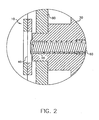
- FIG. 2 shows a cross-sectional view of the above apparatus 10 where heating device 40 has been moved away from organic material 20 so that apparatus 10 is in the first condition and organic material is not being vaporized.
- heating device 40 can be stationary and organic material 20 can be moved away from the heating device, e.g. by reversing metering device 60.
- Heating device 40 is thin and thus has a low thermal mass in contact with organic material 20.
- Metering device 60 feeds organic material 20 in the shape of a thin cylinder, such that organic material 20 has a small cross-sectional area in second temperature-controlled region 50, but has a much larger area in contact with first temperature-controlled region 30, which can act as a heat sink.
- FIG. 3 there is shown a cross-sectional view of another apparatus for controlling the vaporization of organic material in a vaporization source onto a substrate surface in accordance with this invention, showing an alternative way of applying heat to organic material 20.
- Focused radiation 70 is applied onto an exposed surface of organic material 20 and heats a small volume percentage of the initial volume of organic material 20 to vaporization in the second condition of apparatus 10.
- Radiation 70 can be applied by a microwave device, an infrared device, or the like. In the first condition, radiation 70 is turned off.
- Radiation 70 can be turned off or on in a fraction of a second, thus stopping or starting vaporization of organic material 20 in a matter of seconds.
- this method can rapidly control the application of vaporized organic material onto a substrate surface by rapidly controlling the vaporization of the organic material 20 in the vaporization source.
- Apparatus 100 is a vaporization source that includes manifold 110 for containing a quantity of vaporized organic material.
- Manifold 110 includes one or more apertures 150 through which the vaporized organic material passes for deposition onto the surface of substrate 160.
- Substrate 160 can be moved in direction 170 so as to sequentially coat the entire substrate surface.
- Apparatus 100 further includes organic material 120 and heating device 130, for example radiant heaters, to heat a portion of organic material 120 above its vaporization temperature.
- apparatus 100 is shown with a charge of organic material 120, it can be constructed instead to meter organic material into manifold 110 and heat the metered materials, for example by an auger structure and permeable heating element, as shown in other embodiments of this invention.
- all organic material is contained in a single source while only a small volume percentage (less than 10%) of the initial volume of organic material is heated to the vaporization temperature at any time. This reduces the likelihood of material degradation.
- Apparatus 100 further provides hollow member 140 positioned in manifold 110 in the flow path of vaporized organic material.
- Hollow member 140 is a structure operating independently of heating device 130 and is effective in a first condition for limiting the passage of vaporized organic material through apertures 150, and effective in a second condition for facilitating the passage of organic material through aperture 150.
- the outside surface of hollow member 140 is a temperature-control surface, by which we mean that the temperature of the outside surface of hollow member 140 and thereby its immediate surroundings can be controlled by teinperature-controlling material (e.g. refrigerant fluid such as chlorofluorocarbons) that can be delivered at a controlled temperature through the interior of hollow member 140 by a structure for delivering such temperature-controlling material (e.g.
- hollow member 140 In a first condition, hollow member 140 is cooled so as to cause the deposition of vaporized organic material onto the surface of hollow member 140 and not onto the surface of substrate 160. Under these conditions, organic material does not escape apertures 150, and therefore is not deposited on the surface of substrate 160. In a second condition, hollow member 140 is held at approximately the same temperature as the bulk of the interior of manifold 110, and hollow member 140 is effective so as to minimally affect the flow of vaporized organic material to apertures 150 and thereby to the surface of substrate 160. Additional control can be attained by decreasing the heat from heating device 130 when hollow member 140 is effective in its first condition and increasing the heat from heating device 130 when hollow member 140 is effective in its second condition.
- FIG. 5 there is shown a schematic view of another apparatus for controlling the deposition of vaporized organic material onto a substrate surface from a vaporization source in accordance with this invention.
- a quantity of organic material is provided into apparatus 200, which is a vaporization source.
- Organic material can be provided by metering device 230, such as an auger structure as already described. It will be understood that in other embodiments the organic material can also be provided in a bulk charge, of which only a portion is heated to the vaporization temperature at a given time as described above, or vaporized organic material can be provided from heating device distant from the vaporization source. In the latter case, the connection between the vaporization source is maintained above the condensation temperature of the vaporized organic material.
- heat from heating device 240 is applied to the organic material, for example by using an auger structure to move the organic material to a permeable heated element.
- all organic material is contained in a single source while only a small volume percentage (less than 10%) of the initial volume of organic material is heated to the vaporization temperature at any time. This reduces the likelihood of material degradation.
- the organic material is vaporized by heating device 240 into manifold 210 and thereby out apertures 220, to be deposited on the surface of substrate 160 placed close to apertures 220 on the outside of manifold 210.
- Apparatus 200 is so constructed that the conductance of organic vapors in manifold 210 is rapid while the conductance of organic vapors through apertures 220 is slower.
- Flow path 260 and valve 250 represent a structure that can be contiguous to or distant from the manifold 210, that operates independently of heating device 240, and that is effective in a first condition for limiting the passage of vaporized organic material through apertures 220, and effective in a second condition for facilitating the passage of organic material through apertures 220.
- the flow of vaporized organic material can be rapidly diverted from manifold 210 to a first flow path 260 by opening valve 250.
- first flow path 260 is opened by opening valve 250 so that vaporized organic material is not deposited on the surface of substrate 160.
- valve 250 is closed so as to allow organic material to be deposited on substrate 160.
- the deposition of vaporized organic material on the surface of substrate 160 can be rapidly started and stopped.
- FIG. 6 there is shown a schematic view of another apparatus for controlling the deposition of vaporized organic material onto a substrate surface from a vaporization source in accordance with this invention.
- a quantity of organic material is provided into apparatus 270, which is a vaporization source.
- Apparatus 270 includes manifold 210 with one or more apertures 220, a device for heating the organic material either contiguous to or distant from the manifold above the vaporization temperature of the organic material, a reservoir 310, a structure for defining a flow path 290 connecting reservoir 310 to manifold 210, and another structure connects flow path 290 to reservoir 310 so that the pressure of vaporized organic material in manifold 210 can be reduced.
- Organic material can be provided by metering device 230, such as an auger structure as already described. It will be understood that the organic material can also be provided in a bulk charge, of which only a portion is heated to the vaporization temperature at a given time, as described above. Heat from heating device 240 is applied to the organic material, for example by using an auger structure to move the organic material to a permeable heating element. Thus, all organic material is contained in a single source while only a small volume percentage (less than 10%) of the initial volume of organic material is heated to the vaporization temperature at any time. This reduces the likelihood of material degradation.
- the organic material is vaporized by heating device 240 into manifold 210 and thereby out apertures 220, to be deposited on the surface of substrate 160 placed close to apertures 220 on the outside of manifold 210.
- Apparatus 270 is so constructed that the conductance of organic vapors in manifold 210 is rapid while the conductance of organic vapors through apertures 220 is slower.
- Flow path 290, valve 295, reservoir 310, inert gas inlet 280, and valve 285 represent a structure operating independently of heating device 240 and are effective in a first condition for limiting the passage of vaporized organic material through apertures 220, and effective in a second condition for facilitating the passage of organic material through apertures 220.
- First flow path 290 is provided connected to manifold 210.
- Reservoir 310 is provided connectable to first flow path 290 and can serve to store diverted vaporized organic material from manifold 210, for example by providing a temperature of reservoir 310 below the condensation temperature of the diverted organic material.
- Apparatus 270 also includes an inert gas inlet 280 and a valve 285 for providing a supply of inert gas, e.g. nitrogen, to manifold 210.
- the flow of vaporized organic material can be rapidly diverted from manifold 210 to a first flow path 290 by opening valve 295.
- first flow path 290 is opened by opening valve 295, and a supply of inert gas is supplied through inert gas inlet 280 to manifold 210 by opening valve 285, so that vaporized organic material is delivered to reservoir 310. This can rapidly sweep the vaporized organic material from the interior of manifold 210.
- valves 285 and 295 are closed, closing first flow path 290 to reservoir 310, so as to allow organic material to be deposited on substrate 160.
- the deposition of vaporized organic material on the surface of substrate 160 can be rapidly started and stopped.
- One advantage of this apparatus is that it is not necessary to turn off heat source 240 to stop the flow of organic material to an external substrate. Thus, when one is ready to restart coating of an external substrate, one can simply close valves 285 and 295 and rapidly refill manifold 210 with organic material vapors.
- Apparatus 300 is a vaporization source that includes manifold 110 for containing a quantity of vaporized organic material.
- Manifold 110 includes one or more apertures 150 through which the vaporized organic material passes for deposition onto the surface of substrate 160.
- Substrate 160 can be moved in direction 170 so as to sequentially coat the entire surface of substrate 160.
- Apparatus 300 further includes organic material 120 and heating device 130, for example radiant heaters, to heat a portion of organic material 120 above its vaporization temperature.
- apparatus 300 is shown with a charge of organic material 120, it can be constructed to meter organic material into manifold 110 and heat the metered materials, for example by an auger structure and permeable heating element, as shown in other embodiments of this invention.
- all organic material is contained in a single source while only a small volume percentage (less than 10%) of the initial volume of organic material is heated to the vaporization temperature at any time. This reduces the likelihood of material degradation.
- Vaporization apparatus 300 also includes movable element 330 contiguous to the manifold.
- Movable element 330 is a structure operating independently of heating device 130 and is effective in a first condition for limiting the passage of vaporized organic material through apertures 150, and effective in a second condition for facilitating the passage of organic material through apertures 150.
- element 330 limits the flow of vaporized organic material through apertures 150. Under these conditions, vaporized organic material does not escape apertures 150, and therefore does not deposit on the surface of substrate 160.
- movable element 330 permits the flow of vaporized organic material through apertures 150 when it is desired to coat substrate 310. Additional control can be attained by decreasing the heat from heating device 130 when movable element 330 is effective in its first condition and increasing the heat from heating device 130 when movable element 330 is effective in its second condition.
- Apparatus 350 is a vaporization source similar to apparatus 300 above, except that it includes an internal movable element 340 in manifold 110. Movable element 340 can be moved via mechanics internal to manifold 110 or via a baffle manipulator that is partly outside of manifold 110. Movable element 340 can be moved into a position wherein it obstructs apertures 150 and thereby blocks the flow of organic materials through the apertures.
- MEMS micro-electromechanical system
- each individual aperture 150 has its own movable element to limit the flow of vaporized organic material.
- MEMS system can include pistons, plungers, bimetallic ribbons, etc.
- movable elements as shown in these embodiments differ from the use of shutters as practiced in the prior art.
- Shutters that have been used to prevent the coating of a substrate are used to provide a block to the flow of vaporized organic material to the substrate.
- vaporization of the organic material continues unreduced, material vapor continues to leave the source region (i.e. effuses) and is deposited on the shutter and other surfaces not protected by the shutter.
- the movable elements block the apertures through which the vaporized organic material is released to deposit onto the substrate, and thereby reduce the rate of effusion of material from the source region, while maintaining the operating pressure therein.
Abstract
Description
- The present invention relates to the field of physical vapor deposition where a source material is heated to a temperature so as to cause vaporization and create a vapor plume to form a thin film on a surface of a substrate.
- Physical vapor deposition in a vacuum environment is a commonly used way of depositing thin organic material films, for example in small molecule OLED devices. Such methods are well known, for example
Barr in U.S. Patent No. 2,447,789 andTanabe et al. in EP 0 982 411 . The organic materials are often subject to degradation when maintained at or near the desired rate-dependent vaporization temperature for extended periods of time. Exposure of sensitive organic materials to higher temperatures can cause changes in the structure of the molecules and associated changes in material properties. - The organic materials used in OLED devices have a highly nonlinear dependence of vaporization rate on source temperature. A small change in source temperature leads to a very large change in vaporization rate. Despite this, prior art devices employ source temperature as the only way to control vaporization rate. To achieve good temperature control, prior art deposition sources typically utilize heating structures whose solid volume is much larger than the organic charge volume, composed of high thermal-conductivity materials that are well insulated. The high thermal conductivity insures good temperature uniformity through the structure and the large thermal mass helps to maintain the temperature within a critically small range by reducing temperature fluctuations. These measures have the desired effect on steady-state vaporization rate stability but have a detrimental effect at start-up. It is common that these devices must operate for long periods of time (e.g. 2-12 hours) at start-up before steady state temperature distribution and hence a steady vaporization rate is achieved. It is also common that these devices also require long times to cool down, and thus significant amounts of organic material, some of which can be expensive or difficult to synthesize, can be lost. Furthermore the steady state slowly drifts as material is consumed from the sources, and input power must be changed (in order to alter the temperature distribution) to maintain a constant vaporization rate.
- The current method to minimize material time at high temperature and to maximize machine operation time by minimizing the start-up and cool-down times of the material-containing sources requires using duplicate sources of the same material sequentially. For example, rather than using one source continuously for eight days, two sources can be used for four days each or eight sources can be used in a serial process for one day each by overlapping the start-up and cool-down times. Duplicate sources, however, increase equipment size and cost, especially if the number of duplicate sources or the number of materials that require duplicate sources is large.
-
Forrest et al. (U.S. Patent No. 6,337,102 B1 ) disclose a method for vaporizing organic materials and organic precursors and delivering them to a reactor vessel wherein the substrate is situated, and delivery of the vapors generated from solids or liquids is accomplished by use of carrier gases. The organic materials are held at a constant temperature that is high enough to saturate the incoming carrier gas at all possible flow rates. Deposition rate is controlled by adjusting the carrier-gas flow rate. In one embodiment of their invention, Forrest et al. locate the substrates within a suitably large reactor vessel, and the vapors carried thereto mix and react or condense on the substrate. Another embodiment of their invention is directed towards applications involving coating of large area substrates and putting several such deposition processes in serial fashion with one another. For this embodiment, Forrest et al. disclose the use of a gas curtain fed by a gas manifold (defined in the disclosure as "hollow tubes having a line of holes") in order to form a continuous line of depositing material perpendicular to the direction of substrate travel.. - One major problem in the approach disclosed by Forrest et al. is that all of the materials are continuously heated in high thermal mass systems to maintain tight temperature control. This exposure to high temperatures for extended periods of time increases the likelihood of degradation of some materials in the same way as the methods taught by Barr and Tanabe et al. Another problem in the approach disclosed by Forrest et al. is that cool-down and start-up times to reload material are long, due to the high thermal mass of the system and the requirement that all materials be at a uniform temperature before starting the carrier gas flow.
- Also known in the art are systems such as taught by Hoffman et al. of Applied Films GmbH & Co. in their paper from the Society for Information Display 2002 International Symposium, SID Digest 02 pp. 891-893. These systems combine large heated remote sources similar to the type used by Barr and Tanabe et al. with manifolds to distribute the material vapor. These systems suffer from the same problems as the methods taught by Barr, Tanabe et al., and Forrest et al. with respect to material degradation, due to long term exposure to high temperatures and long cool-down and start-up times due to the high thermal mass of the heating system.
- The approaches to vapor delivery as disclosed by Forrest et al. and Hoffman et al. can be characterized as "remote vaporization" wherein a material is converted to vapor in an apparatus external to the deposition zone and more likely external to the deposition chamber. Organic vapors, alone or in combination with carrier gases, are conveyed into the deposition chamber and ultimately to the substrate surface. Great care must be taken using this approach to avoid unwanted condensation in the delivery lines by use of appropriate heating methods. This problem becomes even more critical when contemplating the use of inorganic materials that vaporize to the desired extent at substantially higher temperatures. Furthermore, the delivery of the vaporized material for coating large areas uniformly requires the use of gas manifolds.
- Current remote-vaporization methods suffer from the problems of long material exposure to high temperatures and start-up and cool-down delays due to high thermal mass heating systems; however, these systems have some advantages over the methods taught by Barr and Tanabe et al. with respect to coating uniformity and control of instantaneous deposition rates. Although these remote vaporization methods can stop deposition fairly quickly by closing valves for the carrier gases in the method of Forrest et al. or for the organic vapors in the method of Hoffman et al., the organic vapors and carrier gases downstream of the valves will continue to exit the manifold until the manifold pressure drops to the deposition chamber pressure. Likewise this method can start deposition fairly quickly but organic vapors and carrier gases will not reach steady state deposition rates until the manifold has reached steady state pressure. This is a problem due to remote vaporization combined with structures, such as valves, to control the flow of organic vapors that are also remote from and not contiguous to the manifold. These remote structures do not quickly control the passage of organic material through the manifold apertures, resulting in delays in starting and stopping deposition. Remote vaporization systems with remote valves do not resolve the significant issue of long start-up and cool-down times for loading fresh material, due to the high thermal mass of these systems, nor do they resolve the major issue of material degradation due to extended exposure to high temperature in these systems.
- Furukawa et al., in Japanese Unexamined Patent Application
9-219289 - VanSlyke et al, "Linear Source Deposition of Organic Layers for Full-Color OLED", 2002 SID Inter. Symposium Digest of Technical Papers, pages 886-889 discloses a method and apparatus for evaporating organic material. A volume of organic powder is placed in a quartz boat, vaporized organic material asses by a baffle and exits a manifold with at least one aperture. The organic material is heated by a bottom heater below the vaporization temperature and a top heater to raise the temperature sufficiently to vaporize the upper surface of the organic material.
-
EP 1130129 also discloses a thermal physical vapor deposition structure having a boat with a source. A manifold is also provided through which vaporized material passes. -
WO 2005/083146 provides two heating regions a first heating region maintaining the organic material below the vaporization temperature and a second heating region above the vaporization temperature of the organic material and provides metering of the organic material at a controlled rate from the first region to the second region. -
WO 2006/034019A2 andWO2006/034028 , considered as intermediate prior art disclose methods for delivering particulate material to a vaporization zone, the material being transferred to an auger. - It is therefore an object of the present invention to achieve physical vapor deposition at a steady state with short start and stop times. It is a further object that the vapor deposition can be run continuously and in any orientation. It is a further object to minimize the heat-promoted degradation of organic materials without resorting to large numbers of duplicate sources. It is a further object to minimize the start-up and cool-down times for reloading materials without resorting to duplicate sources.
- This object is achieved by a method as defined by claim 1 for controlling the deposition of vaporized organic material onto a substrate surface. Other aspects appear in dependent claims.
- It is an advantage of the present invention that the deposition of organic material vapors can be started and stopped in a matter of seconds to achieve a steady vaporization rate quickly. This feature minimizes contamination of the deposition chamber walls and conserves the organic materials when a substrate is not being coated.
- It is another advantage of the present invention that the device overcomes the heating and volume limitations of prior art devices in that only a small portion of organic material is heated to the desired rate-dependent vaporization temperature at a controlled rate. It is therefore a feature of the present invention to maintain a steady vaporization rate with a large charge of organic material and with a steady heater temperature. The device permits extended operation of the source with substantially reduced risk of degrading even very temperature-sensitive organic materials. This feature additionally permits materials having different vaporization rates and degradation temperature thresholds to be co-sublimated in the same source. This feature additionally permits short material-reloading times due to the low thermal mass of the heated material.
- It is a further advantage of some embodiments of the present invention that it permits finer rate control and additionally offers an independent measure of the vaporization rate.
- It is a further advantage of some embodiments that the present device achieves substantially higher vaporization rates than in prior art devices without material degradation. Further still, no heater temperature change is required as the source material is consumed.
- It is a further advantage of some embodiments of the present invention that it can provide a vapor source in any orientation, which is not possible with prior-art devices.
-
-
FIG. 1 shows a cross-sectional view of an apparatus for controlling the vaporization of organic material in a vaporization source onto a substrate surface in accordance with this invention; -
FIG. 2 shows a cross-sectional view of the above apparatus in a configuration for controlling the vaporization of organic material in accordance with this invention; -
FIG. 3 shows a cross-sectional view of another apparatus for controlling the vaporization of organic material in a vaporization source onto a substrate surface in accordance with this invention; -
FIG. 4 shows a cross-sectional view of an apparatus for controlling the deposition of vaporized organic material onto a substrate surface from a vaporization source in accordance with this invention; -
FIG. 5 shows a schematic view of another apparatus for controlling the deposition of vaporized organic material onto a substrate surface from a vaporization source in accordance with this invention; -
FIG. 6 shows a schematic view of another apparatus for controlling the deposition of vaporized organic material onto a substrate surface from a vaporization source in accordance with this invention; -
FIG. 7a shows a cross-sectional view of another apparatus in a closed configuration for controlling the deposition of vaporized organic material onto a substrate surface from a vaporization source in accordance with this invention; -
FIG. 7b shows a cross-sectional view of the above apparatus in an open configuration; and -
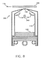
FIG. 8 shows a cross-sectional view of another apparatus in an open configuration for controlling the deposition of vaporized organic material onto a substrate surface from a vaporization source in accordance with this invention. - Turning now to
FIG. 1 , there is shown a cross-sectional view of an apparatus for controlling the deposition of vaporized organic material onto a substrate surface by controlling the vaporization of organic material in a vaporization source onto a substrate surface in accordance with this invention.Apparatus 10 is a vaporization source and includes an initial volume oforganic material 20 and ametering device 60 for advancingorganic material 20 in a controlled manner from first temperature-controlledregion 30 to second temperature-controlledregion 50.Metering device 60 can be e.g. an auger screw or a similar auger structure. Such metering device, and a way of providing a volume of organic material to them, have previously been described by Long et al. in above-cited commonly assignedWO-A-2006/034019 . First temperature-controlledregion 30 can be a region of high thermal mass, e.g. a large base, and can include such materials as metals and ceramics to maintainorganic material 20 at a desired temperature below its vaporization temperature. First temperature-controlledregion 30 can be heated or cooled as needed and includes a first heating device, which can be any well-known heating device, e.g. heating coil, induction heating, heating/cooling tubes, and the like. The first heating device is not shown for clarity. First temperature-controlledregion 30 is heated to and maintained below the vaporization temperature oforganic material 20. - The vaporization temperature is defined as the lowest temperature wherein the vapor pressure of
organic material 20 is sufficient to effectively form a layer of organic material on a substrate. By effectively we mean at a practical manufacturing rate. Because the vapor pressure of a material is a continuous function with respect to temperature, at any non-zero absolute temperature, the material has a non-zero vapor pressure. The above definition of vaporization temperature is useful for describing operating conditions and relative temperatures of various regions within a practical deposition device. - A related matter is that of the condensation temperature. At a given partial pressure of material, the material vapor will condense onto a surface held at or below a measurable temperature. This temperature is defined as the condensation temperature and depends on the partial pressure of the material vapor.
-
Apparatus 10 also provides a manifold, a portion of which is shown bymanifold walls 80. The manifold includes one or more apertures through which the vaporized organic material will pass for deposition onto a substrate surface. Long et al. have discussed examples of suitable manifolds inWO 2005/098079 . The manifold can also consist of a single-aperture heated-wall structure similar to the type commonly referred to as point sources. - Second temperature-controlled
region 50 is the region from the end of first temperature-controlledregion 30 to asecond heating device 40.Second heating device 40 can be a heating element that has a very low thermal mass as seen byorganic material 20. Such heating elements include permeable heating elements such as wire mesh screens and reticulated porous structures including fine ligaments, and can be heated by induction, RF energy, or by conducting a current along its length.Second heating device 40 heatsorganic material 20 above its vaporization temperature in second tempemture-controlledregion 50, so that the vapor pressure of the heated organic material is sufficient to effectively form a layer on a substrate and the organic material adjacent to the permeable heating element vaporizes and is released into the manifold.Organic material 20 is metered at a predetermined controlled rate to second temperature-controlledregion 50 so thatorganic material 20 is vaporized by heat at a controlled rate and the vaporized organic material passes through the permeable heating element, that is,second heating device 40, into the manifold and out through the manifold apertures. In this embodiment thesecond heating device 40 is shown inside the manifold, but for embodiments where thesecond heating device 40 is contiguous to the manifold, thesecond heating device 40 can be outside the manifold as long as the volume of the connection between thesecond heating device 40 and the manifold is small relative to the internal volume of the manifold. For embodiments where the heating device is distant from the manifold, the volume of the connection is not important as long as the connection is maintained above the condensation temperature of the vaporized organic material. - In practice, the vaporization of
organic material 20 can be controlled by controlling the metering oforganic material 20, or by controlling the temperature applied toorganic material 20 at second temperature-controlledregion 50, or both. A controller for controlling the temperature at second temperature-controlledregion 50 and reduces a potential and thereby applies a current tosecond heating device 40, that reduces the RF energy applied tosecond heating device 40, and separatessecond heating device 40 andorganic material 20. In order to separatesecond heating device 40 and organic material 20 a mechanical structure is provided for movingsecond heating device 40 away fromorganic material 20, and reversing the metering device that feedorganic material 20 tosecond heating device 40. In a first condition, the temperature oforganic material 20 is maintained below that needed to effectively form a layer on the substrate, that is, below the vaporization temperature. In a second condition, a small volume percentage of the initial volume oforganic material 20 adjacent to second heating device 40 (that is, the portion between first temperature-controlledregion 30 and second heating device 40) is heated above the vaporization temperature so that the vapor pressure of the heated organic material is sufficient to effectively form a layer on a substrate placed near the apertures of the manifold.FIG. 1 is in the second condition whensecond heating device 40 is heated as described above. Thus, all organic material is contained in a single source while only a small volume percentage (less than 10%) of the initial volume of organic material is heated to the vaporization temperature at any time. This reduces the likelihood of material degradation. - To rapidly reduce the vaporization of
organic material 20,apparatus 10 is put into the first condition. This can be achieved by decreasing the heat from second heating device 40 (e.g. by reducing a potential applied to it so as to reduce the current through it), or by separatingsecond heating device 40 fromorganic material 20, or both.FIG. 2 shows a cross-sectional view of theabove apparatus 10 whereheating device 40 has been moved away fromorganic material 20 so thatapparatus 10 is in the first condition and organic material is not being vaporized. Alternatively,heating device 40 can be stationary andorganic material 20 can be moved away from the heating device, e.g. by reversingmetering device 60. This can change the vaporization rate from greater than 90% of the maximum rate to less than 10% of the maximum rate in less than 5 minutes, and times less than 3 seconds can be achieved. One can also coolorganic material 20, e.g. by cooling first temperature-controlledregion 30. One can use any combination of these techniques to quickly reduce the vaporization rate oforganic material 20. - The ability to reduce the vaporization rate quickly is attained by several features of this invention that provide a thermal time constant of the vaporization process on the order of one second.
Heating device 40 is thin and thus has a low thermal mass in contact withorganic material 20.Metering device 60 feedsorganic material 20 in the shape of a thin cylinder, such thatorganic material 20 has a small cross-sectional area in second temperature-controlledregion 50, but has a much larger area in contact with first temperature-controlledregion 30, which can act as a heat sink. - Turning now to
FIG. 3 , there is shown a cross-sectional view of another apparatus for controlling the vaporization of organic material in a vaporization source onto a substrate surface in accordance with this invention, showing an alternative way of applying heat toorganic material 20.Focused radiation 70 is applied onto an exposed surface oforganic material 20 and heats a small volume percentage of the initial volume oforganic material 20 to vaporization in the second condition ofapparatus 10. Thus, all organic material is contained in a single source while only a small volume percentage (less than 10%) of the initial volume of organic material is heated to the vaporization temperature at any time. This reduces the likelihood of material degradation.Radiation 70 can be applied by a microwave device, an infrared device, or the like. In the first condition,radiation 70 is turned off.Radiation 70 can be turned off or on in a fraction of a second, thus stopping or starting vaporization oforganic material 20 in a matter of seconds. Thus this method can rapidly control the application of vaporized organic material onto a substrate surface by rapidly controlling the vaporization of theorganic material 20 in the vaporization source. - Turning now to
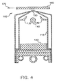
FIG. 4 , there is shown a cross-sectional view of an apparatus for controlling the deposition of vaporized organic material onto a substrate surface from a vaporization source in accordance with this invention.Apparatus 100 is a vaporization source that includesmanifold 110 for containing a quantity of vaporized organic material.Manifold 110 includes one ormore apertures 150 through which the vaporized organic material passes for deposition onto the surface ofsubstrate 160.Substrate 160 can be moved indirection 170 so as to sequentially coat the entire substrate surface.Apparatus 100 further includesorganic material 120 andheating device 130, for example radiant heaters, to heat a portion oforganic material 120 above its vaporization temperature. Althoughapparatus 100 is shown with a charge oforganic material 120, it can be constructed instead to meter organic material intomanifold 110 and heat the metered materials, for example by an auger structure and permeable heating element, as shown in other embodiments of this invention. Thus, all organic material is contained in a single source while only a small volume percentage (less than 10%) of the initial volume of organic material is heated to the vaporization temperature at any time. This reduces the likelihood of material degradation. -
Apparatus 100 further provideshollow member 140 positioned inmanifold 110 in the flow path of vaporized organic material.Hollow member 140 is a structure operating independently ofheating device 130 and is effective in a first condition for limiting the passage of vaporized organic material throughapertures 150, and effective in a second condition for facilitating the passage of organic material throughaperture 150. The outside surface ofhollow member 140 is a temperature-control surface, by which we mean that the temperature of the outside surface ofhollow member 140 and thereby its immediate surroundings can be controlled by teinperature-controlling material (e.g. refrigerant fluid such as chlorofluorocarbons) that can be delivered at a controlled temperature through the interior ofhollow member 140 by a structure for delivering such temperature-controlling material (e.g. a pump or compressor) so as to absorb heat from or deliver heat tohollow member 140. In a first condition,hollow member 140 is cooled so as to cause the deposition of vaporized organic material onto the surface ofhollow member 140 and not onto the surface ofsubstrate 160. Under these conditions, organic material does not escapeapertures 150, and therefore is not deposited on the surface ofsubstrate 160. In a second condition,hollow member 140 is held at approximately the same temperature as the bulk of the interior ofmanifold 110, andhollow member 140 is effective so as to minimally affect the flow of vaporized organic material toapertures 150 and thereby to the surface ofsubstrate 160. Additional control can be attained by decreasing the heat fromheating device 130 whenhollow member 140 is effective in its first condition and increasing the heat fromheating device 130 whenhollow member 140 is effective in its second condition. - Turning now to
FIG. 5 , there is shown a schematic view of another apparatus for controlling the deposition of vaporized organic material onto a substrate surface from a vaporization source in accordance with this invention. A quantity of organic material is provided intoapparatus 200, which is a vaporization source. Organic material can be provided bymetering device 230, such as an auger structure as already described. It will be understood that in other embodiments the organic material can also be provided in a bulk charge, of which only a portion is heated to the vaporization temperature at a given time as described above, or vaporized organic material can be provided from heating device distant from the vaporization source. In the latter case, the connection between the vaporization source is maintained above the condensation temperature of the vaporized organic material. In this embodiment heat fromheating device 240 is applied to the organic material, for example by using an auger structure to move the organic material to a permeable heated element. Thus, all organic material is contained in a single source while only a small volume percentage (less than 10%) of the initial volume of organic material is heated to the vaporization temperature at any time. This reduces the likelihood of material degradation. The organic material is vaporized byheating device 240 intomanifold 210 and thereby outapertures 220, to be deposited on the surface ofsubstrate 160 placed close toapertures 220 on the outside ofmanifold 210.Apparatus 200 is so constructed that the conductance of organic vapors inmanifold 210 is rapid while the conductance of organic vapors throughapertures 220 is slower. Flowpath 260 andvalve 250 represent a structure that can be contiguous to or distant from the manifold 210, that operates independently ofheating device 240, and that is effective in a first condition for limiting the passage of vaporized organic material throughapertures 220, and effective in a second condition for facilitating the passage of organic material throughapertures 220. The flow of vaporized organic material can be rapidly diverted frommanifold 210 to afirst flow path 260 by openingvalve 250. In the first condition,first flow path 260 is opened by openingvalve 250 so that vaporized organic material is not deposited on the surface ofsubstrate 160. In the second condition,valve 250 is closed so as to allow organic material to be deposited onsubstrate 160. The deposition of vaporized organic material on the surface ofsubstrate 160 can be rapidly started and stopped. - Turning now to
FIG. 6 , there is shown a schematic view of another apparatus for controlling the deposition of vaporized organic material onto a substrate surface from a vaporization source in accordance with this invention. A quantity of organic material is provided intoapparatus 270, which is a vaporization source.Apparatus 270 includes manifold 210 with one ormore apertures 220, a device for heating the organic material either contiguous to or distant from the manifold above the vaporization temperature of the organic material, areservoir 310, a structure for defining aflow path 290 connectingreservoir 310 tomanifold 210, and another structure connectsflow path 290 toreservoir 310 so that the pressure of vaporized organic material inmanifold 210 can be reduced. These will be described in further detail. Organic material can be provided bymetering device 230, such as an auger structure as already described. It will be understood that the organic material can also be provided in a bulk charge, of which only a portion is heated to the vaporization temperature at a given time, as described above. Heat fromheating device 240 is applied to the organic material, for example by using an auger structure to move the organic material to a permeable heating element. Thus, all organic material is contained in a single source while only a small volume percentage (less than 10%) of the initial volume of organic material is heated to the vaporization temperature at any time. This reduces the likelihood of material degradation. The organic material is vaporized byheating device 240 intomanifold 210 and thereby outapertures 220, to be deposited on the surface ofsubstrate 160 placed close toapertures 220 on the outside ofmanifold 210.Apparatus 270 is so constructed that the conductance of organic vapors inmanifold 210 is rapid while the conductance of organic vapors throughapertures 220 is slower. Flowpath 290,valve 295,reservoir 310,inert gas inlet 280, andvalve 285 represent a structure operating independently ofheating device 240 and are effective in a first condition for limiting the passage of vaporized organic material throughapertures 220, and effective in a second condition for facilitating the passage of organic material throughapertures 220.First flow path 290 is provided connected tomanifold 210.Reservoir 310 is provided connectable tofirst flow path 290 and can serve to store diverted vaporized organic material frommanifold 210, for example by providing a temperature ofreservoir 310 below the condensation temperature of the diverted organic material. -
Apparatus 270 also includes aninert gas inlet 280 and avalve 285 for providing a supply of inert gas, e.g. nitrogen, tomanifold 210. The flow of vaporized organic material can be rapidly diverted frommanifold 210 to afirst flow path 290 by openingvalve 295. In the first condition,first flow path 290 is opened by openingvalve 295, and a supply of inert gas is supplied throughinert gas inlet 280 tomanifold 210 by openingvalve 285, so that vaporized organic material is delivered toreservoir 310. This can rapidly sweep the vaporized organic material from the interior ofmanifold 210. In the second condition,valves first flow path 290 toreservoir 310, so as to allow organic material to be deposited onsubstrate 160. The deposition of vaporized organic material on the surface ofsubstrate 160 can be rapidly started and stopped. One advantage of this apparatus is that it is not necessary to turn offheat source 240 to stop the flow of organic material to an external substrate. Thus, when one is ready to restart coating of an external substrate, one can simply closevalves - Turning now to
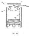
FIG. 7a and7b , there is shown a cross-sectional view of an apparatus for controlling the deposition of vaporized organic materials onto a substrate surface from a vaporization source in accordance with this invention.Apparatus 300 is a vaporization source that includesmanifold 110 for containing a quantity of vaporized organic material.Manifold 110 includes one ormore apertures 150 through which the vaporized organic material passes for deposition onto the surface ofsubstrate 160.Substrate 160 can be moved indirection 170 so as to sequentially coat the entire surface ofsubstrate 160.Apparatus 300 further includesorganic material 120 andheating device 130, for example radiant heaters, to heat a portion oforganic material 120 above its vaporization temperature. Althoughapparatus 300 is shown with a charge oforganic material 120, it can be constructed to meter organic material intomanifold 110 and heat the metered materials, for example by an auger structure and permeable heating element, as shown in other embodiments of this invention. Thus, all organic material is contained in a single source while only a small volume percentage (less than 10%) of the initial volume of organic material is heated to the vaporization temperature at any time. This reduces the likelihood of material degradation. -
Vaporization apparatus 300 also includesmovable element 330 contiguous to the manifold.Movable element 330 is a structure operating independently ofheating device 130 and is effective in a first condition for limiting the passage of vaporized organic material throughapertures 150, and effective in a second condition for facilitating the passage of organic material throughapertures 150. In a first position, shown inFIG. 7a ,element 330 limits the flow of vaporized organic material throughapertures 150. Under these conditions, vaporized organic material does not escapeapertures 150, and therefore does not deposit on the surface ofsubstrate 160. In a second position, shown inFIG. 7b ,movable element 330 permits the flow of vaporized organic material throughapertures 150 when it is desired tocoat substrate 310. Additional control can be attained by decreasing the heat fromheating device 130 whenmovable element 330 is effective in its first condition and increasing the heat fromheating device 130 whenmovable element 330 is effective in its second condition. - Turning now to
FIG. 8 , there is shown a cross-sectional view of another apparatus for controlling the deposition of vaporized organic material onto a substrate surface from a vaporization source in accordance with this invention.Apparatus 350 is a vaporization source similar toapparatus 300 above, except that it includes an internalmovable element 340 inmanifold 110.Movable element 340 can be moved via mechanics internal tomanifold 110 or via a baffle manipulator that is partly outside ofmanifold 110.Movable element 340 can be moved into a position wherein it obstructsapertures 150 and thereby blocks the flow of organic materials through the apertures. - In addition to a single movable element, one can also use a multiplicity of movable elements in a micro-electromechanical system (MEMS), wherein each
individual aperture 150 has its own movable element to limit the flow of vaporized organic material. Such a MEMS system can include pistons, plungers, bimetallic ribbons, etc. - It is to be understood that movable elements as shown in these embodiments differ from the use of shutters as practiced in the prior art. Shutters that have been used to prevent the coating of a substrate are used to provide a block to the flow of vaporized organic material to the substrate. However, vaporization of the organic material continues unreduced, material vapor continues to leave the source region (i.e. effuses) and is deposited on the shutter and other surfaces not protected by the shutter. In this invention, the movable elements block the apertures through which the vaporized organic material is released to deposit onto the substrate, and thereby reduce the rate of effusion of material from the source region, while maintaining the operating pressure therein.
-
- 10
- apparatus
- 20
- organic material
- 30
- first temperature-controlled region
- 40
- heating device
- 50
- second temperature-controlled region
- 60
- metering device
- 70
- radiation
- 80
- manifold wall
- 100
- apparatus
- 110
- manifold
- 120
- organic material
- 130
- heating device
- 140
- hollow member
- 150
- aperture
- 160
- substrate
- 170
- direction
- 200
- apparatus
- 210
- manifold
- 220
- aperture
- 230
- metering device
- 240
- heating device
- 250
- valve
- 260
- flow path
- 270
- apparatus
- 280
- inert gas inlet
- 285
- valve
- 290
- flow path
- 295
- valve
- 300
- apparatus
- 310
- reservoir
- 330
- element
- 340
- element
- 350
- apparatus
Claims (4)
- A method for controlling the deposition of vaporized organic material onto a substrate surface, comprising:a) providing a manifold to distribute vaporized organic material, the manifold having at least one aperture through which vaporized organic material passes for deposition onto the substrate surface;b) providing a volume of organic material in a first region with a first heating device and maintaining the temperature by actively cooling such organic material in a first condition so that its vapor pressure is below that needed to effectively vaporize and form a layer on the substrate, and in a second condition using a second heating device in a second region for heating a volume percentage of the initial volume of such organic material so that the temperature of the heated organic material causes such material to vaporize and pass through the aperture in the manifold to form a layer on the substrate surface;c) providing a rotatable auger and metering by using such auger the organic material from the first region where such organic material is in the first condition, to the second region where it is in the second condition to control the rate of vaporization; andd) separating the second heating device from the organic material by moving the heating device away from the auger so that there is no organic material subject to the second condition.
- The method of claim 1 wherein heating the volume percentage of the initial volume of organic material includes applying radiation onto an exposed surface of the organic material.
- The method of claim 1 further including heating the volume percentage of the initial volume by providing a permeable heating element in a temperature-controlled region and using such heated permeable heating element to vaporize organic material adjacent to such permeable heating element so that the vaporized organic material passes through the permeable heating element and into the manifold and out through the manifold aperture.
- The method of claim 1 wherein during vaporization, less than 10% of the provided volume of organic material is heated to the second condition.
Applications Claiming Priority (2)
| Application Number | Priority Date | Filing Date | Title |
|---|---|---|---|
| US10/984,095 US20060099344A1 (en) | 2004-11-09 | 2004-11-09 | Controlling the vaporization of organic material |
| PCT/US2005/040539 WO2006053017A1 (en) | 2004-11-09 | 2005-11-09 | Method and apparatus for controlling the vaporization of organic material |
Publications (2)
| Publication Number | Publication Date |
|---|---|
| EP1834364A1 EP1834364A1 (en) | 2007-09-19 |
| EP1834364B1 true EP1834364B1 (en) | 2010-12-29 |
Family
ID=35892418
Family Applications (1)
| Application Number | Title | Priority Date | Filing Date |
|---|---|---|---|
| EP05818811A Active EP1834364B1 (en) | 2004-11-09 | 2005-11-09 | Method and apparatus for controlling the vaporization of organic material |
Country Status (8)
| Country | Link |
|---|---|
| US (2) | US20060099344A1 (en) |
| EP (1) | EP1834364B1 (en) |
| JP (1) | JP5144268B2 (en) |
| KR (1) | KR101172410B1 (en) |
| CN (1) | CN101057349B (en) |
| DE (1) | DE602005025695D1 (en) |
| TW (1) | TWI382099B (en) |
| WO (1) | WO2006053017A1 (en) |
Families Citing this family (6)
| Publication number | Priority date | Publication date | Assignee | Title |
|---|---|---|---|---|
| US7989021B2 (en) * | 2005-07-27 | 2011-08-02 | Global Oled Technology Llc | Vaporizing material at a uniform rate |
| JP5325471B2 (en) * | 2007-07-06 | 2013-10-23 | 株式会社半導体エネルギー研究所 | Method for manufacturing light emitting device |
| EP2330653A4 (en) * | 2008-09-24 | 2012-07-04 | Idemitsu Kosan Co | Composite organic electroluminescent material |
| US8425801B2 (en) * | 2009-04-10 | 2013-04-23 | Idemitsu Kosan Co., Ltd. | Composite organic electroluminescent material and production method thereof |
| DE102010007111B4 (en) * | 2010-02-05 | 2012-02-16 | Von Ardenne Anlagentechnik Gmbh | Process and powder mixture for coating substrates from the vapor phase |
| CN104711514B (en) * | 2015-04-07 | 2017-05-31 | 合肥京东方光电科技有限公司 | A kind of film formation device and method |
Citations (2)
| Publication number | Priority date | Publication date | Assignee | Title |
|---|---|---|---|---|
| WO2006034019A2 (en) * | 2004-09-21 | 2006-03-30 | Eastman Kodak Company | Delivering particulate material to a vaporization zone |
| WO2006034028A2 (en) * | 2004-09-21 | 2006-03-30 | Eastman Kodak Company | Delivering particulate material to a vaporization source |
Family Cites Families (41)
| Publication number | Priority date | Publication date | Assignee | Title |
|---|---|---|---|---|
| US2447789A (en) * | 1945-03-23 | 1948-08-24 | Polaroid Corp | Evaporating crucible for coating apparatus |
| GB1253124A (en) | 1969-02-28 | 1971-11-10 | ||
| DE3200848C2 (en) * | 1982-01-14 | 1984-09-27 | GfO Gesellschaft für Oberflächentechnik mbH, 7070 Schwäbisch Gmünd | Device for charging evaporators in evaporation systems |
| JPS59177365A (en) * | 1983-03-24 | 1984-10-08 | Matsushita Electric Ind Co Ltd | Method and device for evaporation |
| JPH0743322B2 (en) | 1985-07-19 | 1995-05-15 | 株式会社日立製作所 | Inspection method and device |
| US4885211A (en) * | 1987-02-11 | 1989-12-05 | Eastman Kodak Company | Electroluminescent device with improved cathode |
| US4769292A (en) * | 1987-03-02 | 1988-09-06 | Eastman Kodak Company | Electroluminescent device with modified thin film luminescent zone |
| US5041719A (en) * | 1990-06-01 | 1991-08-20 | General Electric Company | Two-zone electrical furnace for molecular beam epitaxial apparatus |
| JPH05117864A (en) | 1991-06-25 | 1993-05-14 | Anelva Corp | Cvd device |
| JPH0530761U (en) | 1991-09-30 | 1993-04-23 | 京セラ株式会社 | Defect observation device |
| JPH09219289A (en) | 1996-02-09 | 1997-08-19 | Chisso Corp | Organic thin film electroluminescent element and its manufacture |
| US5849089A (en) * | 1997-03-14 | 1998-12-15 | Kabushiki Kaisha Toshiba | Evaporator for liquid raw material and evaporation method therefor |
| EP0987700B1 (en) * | 1997-05-08 | 2004-08-25 | Matsushita Electric Industrial Co., Ltd. | Device and method for manufacturing an optical recording medium |
| JPH1161386A (en) * | 1997-08-22 | 1999-03-05 | Fuji Electric Co Ltd | Film forming device of organic thin film light emitting element |
| US6337102B1 (en) * | 1997-11-17 | 2002-01-08 | The Trustees Of Princeton University | Low pressure vapor phase deposition of organic thin films |
| JPH11251067A (en) * | 1998-03-02 | 1999-09-17 | Junji Kido | Organic electroluminescence element |
| WO1999064208A1 (en) * | 1998-06-09 | 1999-12-16 | Sony Corporation | Robot and method of its attitude control |
| JP2000068055A (en) | 1998-08-26 | 2000-03-03 | Tdk Corp | Evaporation source for organic el element, manufacturing device for organic el element using the same and manufacture thereof |
| JP3610837B2 (en) | 1998-09-18 | 2005-01-19 | 株式会社日立製作所 | Sample surface observation method and apparatus, defect inspection method and apparatus |
| US6123993A (en) * | 1998-09-21 | 2000-09-26 | Advanced Technology Materials, Inc. | Method and apparatus for forming low dielectric constant polymeric films |
| JP2000248358A (en) | 1999-03-01 | 2000-09-12 | Casio Comput Co Ltd | Vapor deposition device and vapor deposition method |
| TW521303B (en) * | 2000-02-28 | 2003-02-21 | Semiconductor Energy Lab | Electronic device |
| US6237529B1 (en) | 2000-03-03 | 2001-05-29 | Eastman Kodak Company | Source for thermal physical vapor deposition of organic electroluminescent layers |
| US6660328B1 (en) * | 2000-03-31 | 2003-12-09 | Florida State University Research Foundation | Powder precursor delivery system for chemical vapor deposition |
| EP1167566B1 (en) * | 2000-06-22 | 2011-01-26 | Panasonic Electric Works Co., Ltd. | Apparatus for and method of vacuum vapor deposition |
| JP4153652B2 (en) | 2000-10-05 | 2008-09-24 | 株式会社東芝 | Pattern evaluation apparatus and pattern evaluation method |
| US6467427B1 (en) | 2000-11-10 | 2002-10-22 | Helix Technology Inc. | Evaporation source material supplier |
| JP4906018B2 (en) | 2001-03-12 | 2012-03-28 | 株式会社半導体エネルギー研究所 | Film forming method, light emitting device manufacturing method, and film forming apparatus |
| US20030015140A1 (en) * | 2001-04-26 | 2003-01-23 | Eastman Kodak Company | Physical vapor deposition of organic layers using tubular sources for making organic light-emitting devices |
| EP1451386A1 (en) | 2001-12-04 | 2004-09-01 | Primaxx, Inc. | Chemical vapor deposition vaporizer |
| WO2003083169A1 (en) * | 2002-04-01 | 2003-10-09 | Ans Inc | Apparatus and method for depositing organic matter of vapor phase |
| JP2003293121A (en) * | 2002-04-05 | 2003-10-15 | Cluster Ion Beam Technology Kk | Vapor deposition crucible having means for supplying vapor deposition material |
| US7025832B2 (en) * | 2002-07-19 | 2006-04-11 | Lg Electronics Inc. | Source for thermal physical vapor deposition of organic electroluminescent layers |
| JP4901090B2 (en) | 2004-10-06 | 2012-03-21 | 株式会社ニコン | Defect inspection method and defect detection apparatus |
| US7643137B2 (en) | 2003-03-26 | 2010-01-05 | Nikon Corporation | Defect inspection apparatus, defect inspection method and method of inspecting hole pattern |
| US6837939B1 (en) * | 2003-07-22 | 2005-01-04 | Eastman Kodak Company | Thermal physical vapor deposition source using pellets of organic material for making OLED displays |
| TWI242463B (en) | 2003-08-28 | 2005-11-01 | Ind Tech Res Inst | Apparatus and process for vacuum sublimation |
| US7339139B2 (en) * | 2003-10-03 | 2008-03-04 | Darly Custom Technology, Inc. | Multi-layered radiant thermal evaporator and method of use |
| JP4552859B2 (en) | 2003-10-27 | 2010-09-29 | 株式会社ニコン | Surface inspection apparatus and surface inspection method |
| US7232588B2 (en) | 2004-02-23 | 2007-06-19 | Eastman Kodak Company | Device and method for vaporizing temperature sensitive materials |
| US7364772B2 (en) | 2004-03-22 | 2008-04-29 | Eastman Kodak Company | Method for coating an organic layer onto a substrate in a vacuum chamber |
-
2004
- 2004-11-09 US US10/984,095 patent/US20060099344A1/en not_active Abandoned
-
2005
- 2005-11-08 TW TW094139065A patent/TWI382099B/en active
- 2005-11-09 EP EP05818811A patent/EP1834364B1/en active Active
- 2005-11-09 CN CN2005800383864A patent/CN101057349B/en active Active
- 2005-11-09 WO PCT/US2005/040539 patent/WO2006053017A1/en active Application Filing
- 2005-11-09 JP JP2007540188A patent/JP5144268B2/en active Active
- 2005-11-09 DE DE602005025695T patent/DE602005025695D1/en active Active
- 2005-11-09 KR KR1020077010468A patent/KR101172410B1/en active IP Right Grant
-
2010
- 2010-05-24 US US12/786,182 patent/US8012537B2/en active Active
Patent Citations (2)
| Publication number | Priority date | Publication date | Assignee | Title |
|---|---|---|---|---|
| WO2006034019A2 (en) * | 2004-09-21 | 2006-03-30 | Eastman Kodak Company | Delivering particulate material to a vaporization zone |
| WO2006034028A2 (en) * | 2004-09-21 | 2006-03-30 | Eastman Kodak Company | Delivering particulate material to a vaporization source |
Also Published As
| Publication number | Publication date |
|---|---|
| TW200624577A (en) | 2006-07-16 |
| JP5144268B2 (en) | 2013-02-13 |
| WO2006053017A1 (en) | 2006-05-18 |
| CN101057349A (en) | 2007-10-17 |
| US20100233367A1 (en) | 2010-09-16 |
| DE602005025695D1 (en) | 2011-02-10 |
| EP1834364A1 (en) | 2007-09-19 |
| KR20070074616A (en) | 2007-07-12 |
| CN101057349B (en) | 2010-06-23 |
| TWI382099B (en) | 2013-01-11 |
| US20060099344A1 (en) | 2006-05-11 |
| JP2008519904A (en) | 2008-06-12 |
| KR101172410B1 (en) | 2012-08-09 |
| US8012537B2 (en) | 2011-09-06 |
Similar Documents
| Publication | Publication Date | Title |
|---|---|---|
| EP1831421B1 (en) | Controlling the application of vaporized organic material | |
| US8012537B2 (en) | Controlling the vaporization of organic material | |
| US7625601B2 (en) | Controllably feeding organic material in making OLEDs | |
| JP2007500794A (en) | Thin film evaporation evaporator | |
| JP2009097044A (en) | Film deposition apparatus and film deposition method | |
| JP4074574B2 (en) | Organic vapor deposition equipment | |
| JP2008169456A (en) | Vacuum deposition system | |
| JP3962349B2 (en) | Vapor phase organic material vapor deposition method and vapor phase organic material vapor deposition apparatus using the same | |
| EP1893785B1 (en) | Method for feeding powdered or granular material | |
| EP1877596B1 (en) | Metering material to promote rapid vaporization | |
| JP4519653B2 (en) | Apparatus and method for depositing a coating material |
Legal Events
| Date | Code | Title | Description |
|---|---|---|---|
| PUAI | Public reference made under article 153(3) epc to a published international application that has entered the european phase |
Free format text: ORIGINAL CODE: 0009012 |
|
| 17P | Request for examination filed |
Effective date: 20070521 |
|
| AK | Designated contracting states |
Kind code of ref document: A1 Designated state(s): DE GB NL |
|
| 17Q | First examination report despatched |
Effective date: 20071113 |
|
| DAX | Request for extension of the european patent (deleted) | ||
| RBV | Designated contracting states (corrected) |
Designated state(s): DE GB NL |
|
| RBV | Designated contracting states (corrected) |
Designated state(s): DE GB NL |
|
| RAP1 | Party data changed (applicant data changed or rights of an application transferred) |
Owner name: GLOBAL OLED TECHNOLOGY LLC |
|
| GRAP | Despatch of communication of intention to grant a patent |
Free format text: ORIGINAL CODE: EPIDOSNIGR1 |
|
| GRAS | Grant fee paid |
Free format text: ORIGINAL CODE: EPIDOSNIGR3 |
|
| GRAA | (expected) grant |
Free format text: ORIGINAL CODE: 0009210 |
|
| AK | Designated contracting states |
Kind code of ref document: B1 Designated state(s): DE GB NL |
|
| REG | Reference to a national code |
Ref country code: GB Ref legal event code: FG4D |
|
| REF | Corresponds to: |
Ref document number: 602005025695 Country of ref document: DE Date of ref document: 20110210 Kind code of ref document: P |
|
| REG | Reference to a national code |
Ref country code: DE Ref legal event code: R096 Ref document number: 602005025695 Country of ref document: DE Effective date: 20110210 |
|
| REG | Reference to a national code |
Ref country code: NL Ref legal event code: VDEP Effective date: 20101229 |
|
| PG25 | Lapsed in a contracting state [announced via postgrant information from national office to epo] |
Ref country code: NL Free format text: LAPSE BECAUSE OF FAILURE TO SUBMIT A TRANSLATION OF THE DESCRIPTION OR TO PAY THE FEE WITHIN THE PRESCRIBED TIME-LIMIT Effective date: 20101229 |
|
| PLBE | No opposition filed within time limit |
Free format text: ORIGINAL CODE: 0009261 |
|
| STAA | Information on the status of an ep patent application or granted ep patent |
Free format text: STATUS: NO OPPOSITION FILED WITHIN TIME LIMIT |
|
| 26N | No opposition filed |
Effective date: 20110930 |
|
| REG | Reference to a national code |
Ref country code: DE Ref legal event code: R097 Ref document number: 602005025695 Country of ref document: DE Effective date: 20110930 |
|
| REG | Reference to a national code |
Ref country code: DE Ref legal event code: R079 Ref document number: 602005025695 Country of ref document: DE Free format text: PREVIOUS MAIN CLASS: H01L0051560000 Ipc: H10K0050000000 |
|
| PGFP | Annual fee paid to national office [announced via postgrant information from national office to epo] |
Ref country code: GB Payment date: 20231123 Year of fee payment: 19 |
|
| PGFP | Annual fee paid to national office [announced via postgrant information from national office to epo] |
Ref country code: DE Payment date: 20231121 Year of fee payment: 19 |